

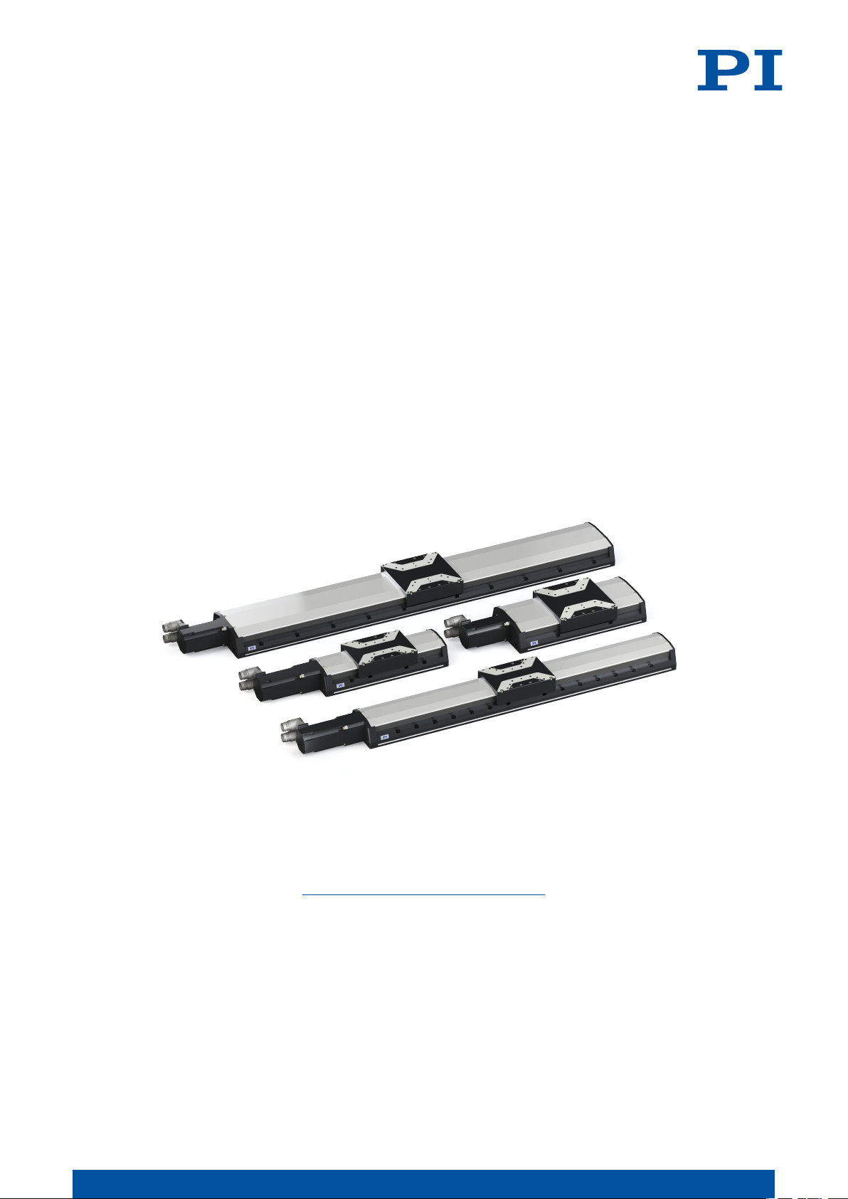
PI L-417.099232B, L-417.059232B, L-417.139232B, L-417.339232B, L-417.179232B User Manual
...Page 1
L417M0010EN ‒ 7/9/2019
User Manual
L-417.XX9232B HIGH-LOAD LINEAR STAGE
M O T I O N | P O S I T I O N I N G
Page 2

CONTENTS
L417M0010EN ‒ 7/9/2019
Contents
1 Legal Information.........................................................................................................4
2 About this Document..................................................................................................5
2.1 Objective and Target Group..............................................................................5
2.2 Explanation of Symbols....................................................................................5
2.2.1 Typographic Conventions................................................................. 5
2.2.2 Symbols Used.................................................................................... 5
2.3 Figures................................................................................................................6
2.4 Downloading Manuals...................................................................................... 6
3 Safety............................................................................................................................7
3.1 Intended Use......................................................................................................7
3.2 General Safety Instructions.............................................................................. 7
3.3 Organizational Measures.................................................................................. 7
3.3.1 User Manual....................................................................................... 7
3.3.2 General Personnel Qualification.......................................................7
4 Product Description..................................................................................................... 8
4.1 Model Overview.................................................................................................8
4.2 Product Labeling................................................................................................8
4.2.1 Type Plate........................................................................................... 9
4.3 Scope of Delivery...............................................................................................9
4.4 Overview.......................................................................................................... 10
4.4.1 Base Body......................................................................................... 10
4.4.2 Drive.................................................................................................. 10
4.4.3 Holding brake................................................................................... 11
4.4.4 Purge Air System..............................................................................11
4.5 Direction of Motion..........................................................................................13
4.6 Suitable Electronics......................................................................................... 13
5 Unpacking.................................................................................................................. 14
6 Installation................................................................................................................. 15
6.1 Mounting the L-417.xx9232B........................................................................... 15
6.2 Connecting the L-417.xx9232B to the Protective Earth Conductor............... 16
6.3 Mounting the Load onto the L-417.xx9232B...................................................18
6.4 Connecting the L-417.xx9232B.........................................................................19
7 Startup / Operation...................................................................................................21
7.1 Starting and Operating the L-417.xx9232B..................................................... 21
8 Maintenance...............................................................................................................23
8.1 Maintenance Run.............................................................................................23
8.2 Relubricating....................................................................................................23
8.3 Cleaning............................................................................................................23
8.4 Moving the Motion Platform by Hand........................................................... 24
2
M O T I O N | P O S I T I O N I N G
Page 3

CONTENTS
L417M0010EN ‒ 7/9/2019
9 Troubleshooting.........................................................................................................25
10 Transportation............................................................................................................26
11 Customer Service Department.................................................................................27
12 Technical Data............................................................................................................ 28
12.1 Specifications...................................................................................................28
12.2 Maximum Ratings........................................................................................... 30
12.3 Ambient Conditions and Classifications........................................................30
12.4 Dimensions...................................................................................................... 31
13 Old Equipment Disposal........................................................................................... 33
14 Appendix.................................................................................................................... 34
14.1 Pin Assignment................................................................................................34
14.1.1 Drive Connector............................................................................... 34
14.1.2 Rotary Encoder Connector.............................................................. 34
14.1.3 Limit Switch Connector................................................................... 35
14.2 Limit Switch Specifications.............................................................................36
14.3 PTC Temperature Sensor................................................................................ 36
14.4 Commutation Encoder.................................................................................... 36
14.5 Holding Brake Specifications..........................................................................37
15 EU Declaration of Conformity...................................................................................38
3
M O T I O N | P O S I T I O N I N G
Page 4

1 LEGAL INFORMATION L417M0010EN ‒ 7/9/2019
1 Legal Information
The following company names and brands are registered trademarks of Physik Instrumente
(PI) GmbH & Co. KG:
PI®, PIC®, NanoCube®, PICMA®, PIFOC, PILine®, NEXLINE®, PiezoWalk®, PicoCube®,
PiezoMove®, PIMikroMove, NEXACT®, Picoactuator®, PInano®, NEXSHIFT®, PITOUCH®,
PIMag®, PIHera, Q-Motion®
The patents held by PI can be found in our list at http://www.physikinstrumente.com/en/
about-pi/patents.
© 2019 Physik Instrumente (PI) GmbH & Co. KG, Karlsruhe, Germany. The text, photographs,
and drawings in this manual are protected by copyright. With regard thereto, Physik
Instrumente (PI) GmbH & Co. KG reserves all rights. The use of any text, images and
drawings is permitted only in part and only when indicating the source.
Original instructions
First print: 7/9/2019
Document number: L417M0010en, ASt
Subject to change. This manual is superseded by any new release. The latest versions of the
user manuals are available for download (p. 6) at www.pi.ws.
Publisher:
PI miCos GmbH
Freiburger Strasse 30
79427 Eschbach
Germany
[email protected]
www.pi.de
Customer service department:
Physik Instrumente (PI) GmbH & Co. KG
Auf der Roemerstrasse 1
76228 Karlsruhe
Germany
[email protected]
www.pi.de
4
M O T I O N | P O S I T I O N I N G
Page 5
2 ABOUT THIS DOCUMENT L417M0010EN ‒ 7/9/2019
2 About this Document
2.1 Objective and Target Group
This user manual contains the information needed for the intended use of the L-417.xx9232B.
Basic knowledge of closed-loop systems, motion control concepts, and applicable safety
measures is assumed.
2.2 Explanation of Symbols
This chapter explains the symbols and markings used by PI in their user manuals.
2.2.1
Typographic Conventions
Symbol / Label Meaning
1.
2.
■ List item
p. 5 Cross-reference to page 5
RS-232
Start > Settings
POS?
Device S/N
5
2.2.2 Symbols Used
Symbol / Label Meaning
Action consisting of several steps whose sequential order must be observed
Labeling of an operating element on the product (example: socket of
the RS-232 interface)
Menu path in the PC software (example: to open the menu, the
and
Settings
Command line or a command from PI's General Command Set (GCS)
(example: command to get the axis position)
Parameter name (example: parameter where the serial number is stored)
Value that must be entered or selected via the PC software
menus must be clicked successively)
Start
General hazard symbol
DANGER
Dangerous situation
Failure to observe can lead to death or serious injury.
► Measures for avoiding the risk.
WARNING
Dangerous situation
Failure to observe can lead to serious injury.
► Action to take to avoid the risk.
5
M O T I O N | P O S I T I O N I N G
Page 6

2 ABOUT THIS DOCUMENT
CAUTION
Dangerous situation
Failure to observe can lead to minor injury.
► Actions to take to avoid the risk.
NOTICE
Dangerous situation
Failure to observe can lead to material damage.
► Action to take to avoid the risk.
Information
Additional information on the L-417.xx9232B that can affect your application.
2.3 Figures
For better understandability, the colors, proportions and degree of detail in illustrations can
deviate from the actual circumstances. Photographic illustrations may also differ and must
not be seen as guaranteed properties.
L417M0010EN ‒ 7/9/2019
2.4 Downloading Manuals
The latest versions of the user manuals can be downloaded (p. 6) at www.pi.ws.
For products that are supplied with software (data storage device in the scope of delivery),
access to the manuals is protected by a password. Protected content is only displayed on the
website after entering the access data. You need the data storage device for the product to
get the access data.
If a manual is missing or problems occur with downloading, contact our customer service
department (p. 27).
Downloading Manuals
1. Open the website www.pi.ws.
2. If the product was shipped with a data storage device: Log into the website:
a)
Click Login.
b) Enter the login data.
The login data is in the [...]_Releasenews_[...].pdf in the Manuals directory on the
data storage device.
If necessary: Follow the link and register yourself to get the login data.
c)
Click Login or press the
3. Search for the product:
a)
Click Search.
b) Enter the product number up to the period (e.g., L-417) into the search field.
c)
Click Start search or press the
d)
If necessary: Click Load more results at the bottom of the list.
4. Click the corresponding product in the list of search results.
5.
Click the Downloads tab.
➔
The manuals are shown under
6. Click the desired manual and save it.
Enter key.
Enter key.
Documentation
.
6
M O T I O N | P O S I T I O N I N G
Page 7

3 SAFETY
3 Safety
3.1 Intended Use
The L-417.xx9232B is a laboratory device as defined by DIN EN 61010-1. It is intended for
indoor use and use in an environment that is free of dirt, oil, and lubricants.
In accordance with its design, the L-417.xx9232B is intended for positioning, adjusting and
shifting loads in one axis at various velocities. The L-417.xx9232B is not intended for
applications in areas, in which a failure would present severe risks to human beings or the
environment.
If the L-417.xx9232B does not have a holding brake, it is only intended for operation with a
horizontally aligned motion axis.
The intended use of the L-417.xx9232B is only possible when completely mounted and
connected. The thermal protection sensor built into the L-417.xx9232B's motor must be
evaluated and monitored. The L-417.xx9232B must be operated with suitable
electronics (p. 13). The electronics are not in the scope of delivery of the L-417.xx9232B.
The L-417.xx9232B may not be used for purposes other than those stated in this user manual.
The L-417.xx9232B may only be used in compliance with the technical specifications and
instructions in this user manual.
L417M0010EN ‒ 7/9/2019
3.2 General Safety Instructions
The L-417.xx9232B is built according to state-of-the-art technology and recognized safety
standards. Improper use of the L-417.xx9232B may result in personal injury and/or damage to
the L-417.xx9232B.
► Use the L-417.xx9232B only for its intended purpose and if it is in perfect condition.
► Read the user manual.
► Eliminate any faults and malfunctions that are likely to affect safety immediately.
The operator is responsible for correct installation and operation of the L-417.xx9232B.
3.3 Organizational Measures
3.3.1 User Manual
►
Always keep this user manual available with the L-417.xx9232B. The latest versions of the
user manuals can be downloaded (p. 6) at www.pi.ws.
► Add all information from the manufacturer such as supplements or technical notes to the
user manual.
► If you give the L-417.xx9232B to a third party, also include this user manual as well as
other relevant information provided by the manufacturer.
► Only use the device on the basis of the complete user manual. Missing information due to
an incomplete user manual can lead to serious or fatal injuries and damage to equipment.
► Only install and operate the L-417.xx9232B after you have read and understood this user
manual.
7
3.3.2
General Personnel Qualification
The L-417.xx9232B may only be installed, started up, operated, maintained, and cleaned by
authorized and appropriately qualified personnel.
M O T I O N | P O S I T I O N I N G
Page 8
1
1
3
2
2
4
2
5
6
4 PRODUCT DESCRIPTION
L417M0010EN ‒ 7/9/2019
4 Product Description
4.1 Model Overview
High-load linear stage, xx mm travel range, 166 mm width, 450 N load capacity,
incremental rotary encoder with A/B quadrature signal transmission, 20000 counts/
rev, holding brake, synchronous servo motor, to 320 V
Product number Travel range: xx
L-417.059232B 102 mm (4")
L-417.099232B 204 mm (8")
L-417.139232B 305 mm (12")
L-417.179232B 407 mm (16")
L-417.219232B 508 mm (20")
L-417.259232B 610 mm (24")
L-417.339232B 813 mm (32")
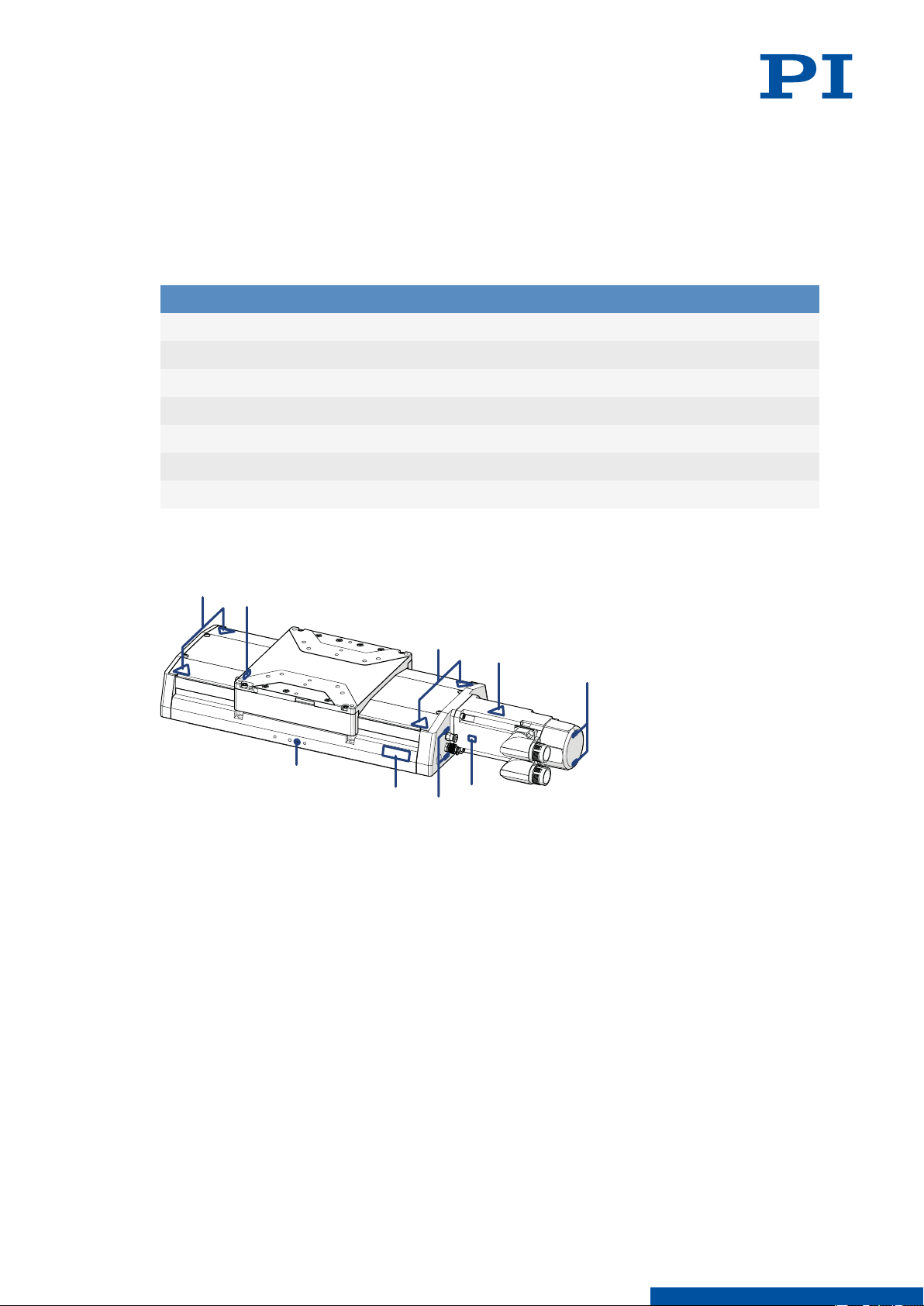
4.2 Product Labeling
Figure 1: Product labels on the L-417.xx9232B
1. Warning symbol: Risk of crushing
2. Connector labels
3. Warning symbol: Hot surface
4. Warning symbol: Electrostatic-sensitive device
5. Type plate
6. Protective earth connector
8
M O T I O N | P O S I T I O N I N G
Page 9
4 PRODUCT DESCRIPTION L417M0010EN ‒ 7/9/2019
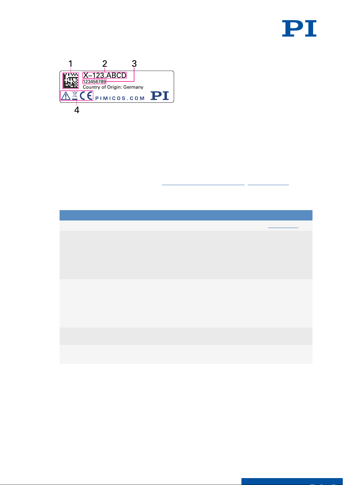
4.2.1 Type Plate
Figure 2: Type plate of the L-417.xx9232B
1. Data matrix code (example; contains the serial number)
2. Product number (example)
3. Serial number (example), individual for each L-417.xx9232B
Meaning of the position (counting from the left):
1 = internal information,
2 and 3 = year of manufacture,
4 to 9 = consecutive numbers
4. Warning and conformity symbols (old equipment disposal (p. 33), CE mark (p. 38))
4.3 Scope of Delivery
Product number Description
L-417.xx9232B Linear stage according to the order (p. 8)
For L-417.xx9232B with xx = 05, 09, 13, 17:
L417B0014
For L-417.xx9232B with xx = 21, 25, 33:
L417B0015
MP187EK Short instructions for positioners with elec-
For L-417.xx9232B with xx = 21, 25, 33:
V417B0029
Mounting kit for mounting the L-417.xx9232B
and installation material, consisting of
■ 12 socket head screws, ISO 4762 M6×30
■ 2 dowel pins, ISO 8734, 4 m6 × 12
■ 12 flat washers, ISO 7092, D11 d6.4 h1, 6
mm
Mounting kit for mounting the L-417.xx9232B
and installation material, consisting of
■ 20 socket head screws, ISO 4762 M 6 × 30
■ 2 dowel pins, ISO 8734, 4m6 × 12
■ 20 flat washers, ISO 7092, D11 d6.4 h1, 6
mm
tric motors to 320 V
Transport means: Carrying aid for the
L-417.xx9232B
9
M O T I O N | P O S I T I O N I N G
Page 10
6
1
2
3
4
5
7
4 PRODUCT DESCRIPTION
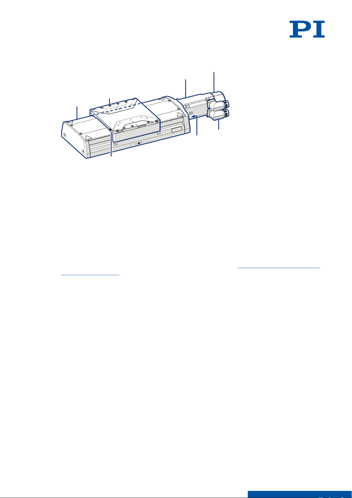
4.4 Overview
Figure 3: Elements of the L-417.xx9232B
1. Base body
2. Motion platform
3. Drive
4. Holding brake
5. Drive and sensor connector
6. Connectors for limit switch signals and purge air
7. Grease nipple for relubricating the drive screw
L417M0010EN ‒ 7/9/2019
4.4.1
4.4.2
Base Body
The base body is the basis of the positioner. The L-417.xx9232B is mounted onto a surface via
the base body (p. 15).
The base body comprises the following subassembly (subassemblies):
Drive screw
The drive screw converts the rotary motion of the drive to linear motion of the motion
platform.
Limit switches
The limit switches are sensors at each end of the travel range that enable the electronics to
abort motion in order to prevent the motion platform from colliding with the mechanical
hard stop.
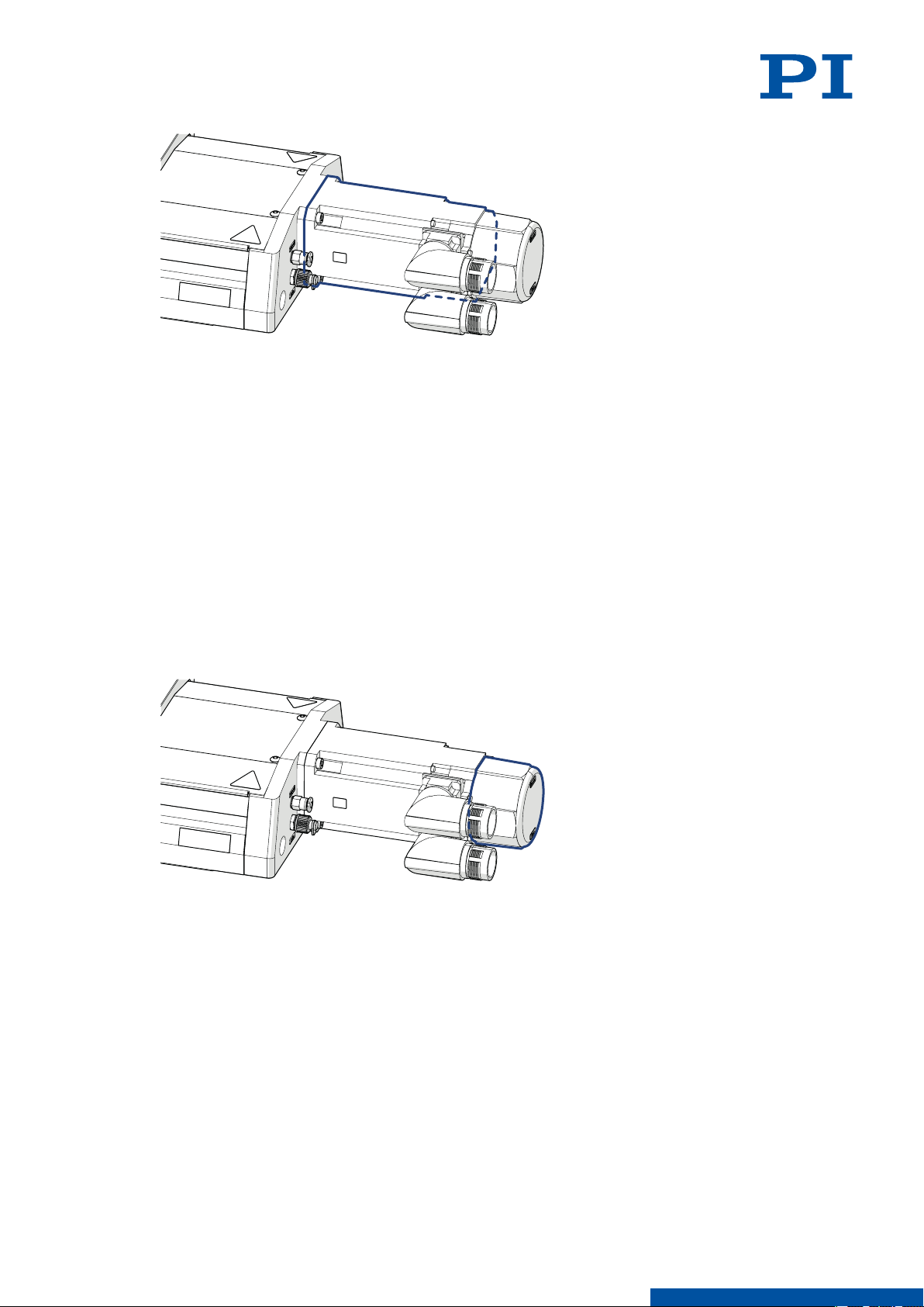
Drive
The drive generates the torque required for the dynamics of the motion platform.
10
M O T I O N | P O S I T I O N I N G
Page 11
4 PRODUCT DESCRIPTION
The drive comprises the following subassembly (subassemblies):
Motor
The motor generates the torque required for the dynamics of the motion platform.
Rotary encoder
The rotary encoder measures the motor shaft's angle of rotation. This signal can be used by
suitable electronics for commutating the motor and for calculating the position of the motion
platform after a reference move .
L417M0010EN ‒ 7/9/2019
4.4.3
4.4.4
Holding brake
The holding brake blocks the drivetrain at rest.
The holding brake is designed for holding only and is not suitable for continuous braking
during operation.
The holding brake blocks in a zero voltage state.
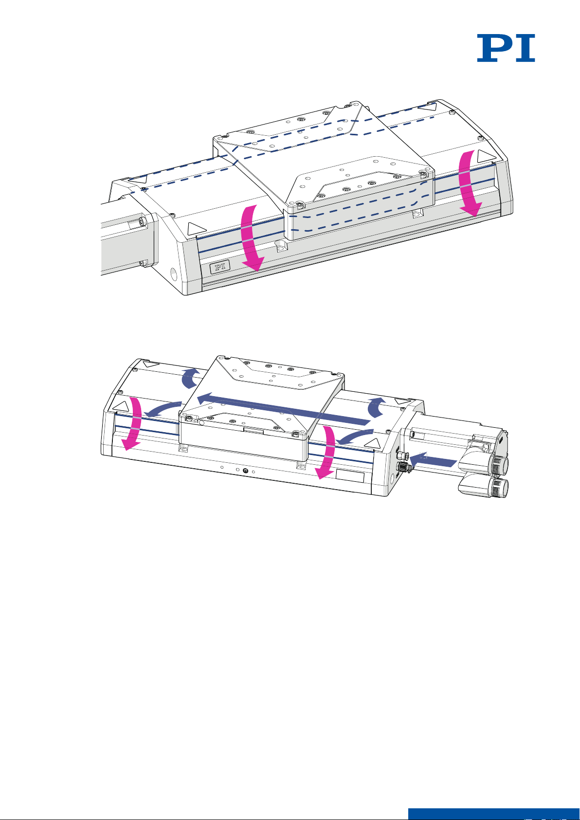
Purge Air System
The purge air system protects the drive and guides of the L-417.xx9232B against surrounding
dust.
The purge air system comprises the following subassembly (subassemblies):
11
M O T I O N | P O S I T I O N I N G
Page 12
4 PRODUCT DESCRIPTION
Passive dust protection
The passive dust protection consists of covering strips that seal the openings on the side of
the L-417.xx9232B's base body and therefore reduces the amount of dust that can penetrate.
L417M0010EN ‒ 7/9/2019
Active dust protection
The active dust protection consists of a purge air connector on the base body of the
L-417.xx9232B, which creates a slight overpressure in the L-417.xx9232B and therefore
reduces the amount of dust that can penetrate.
12
M O T I O N | P O S I T I O N I N G
Page 13
Positive Direction of Motion
Negative Limit Switch
Positive Limit Switch
4 PRODUCT DESCRIPTION
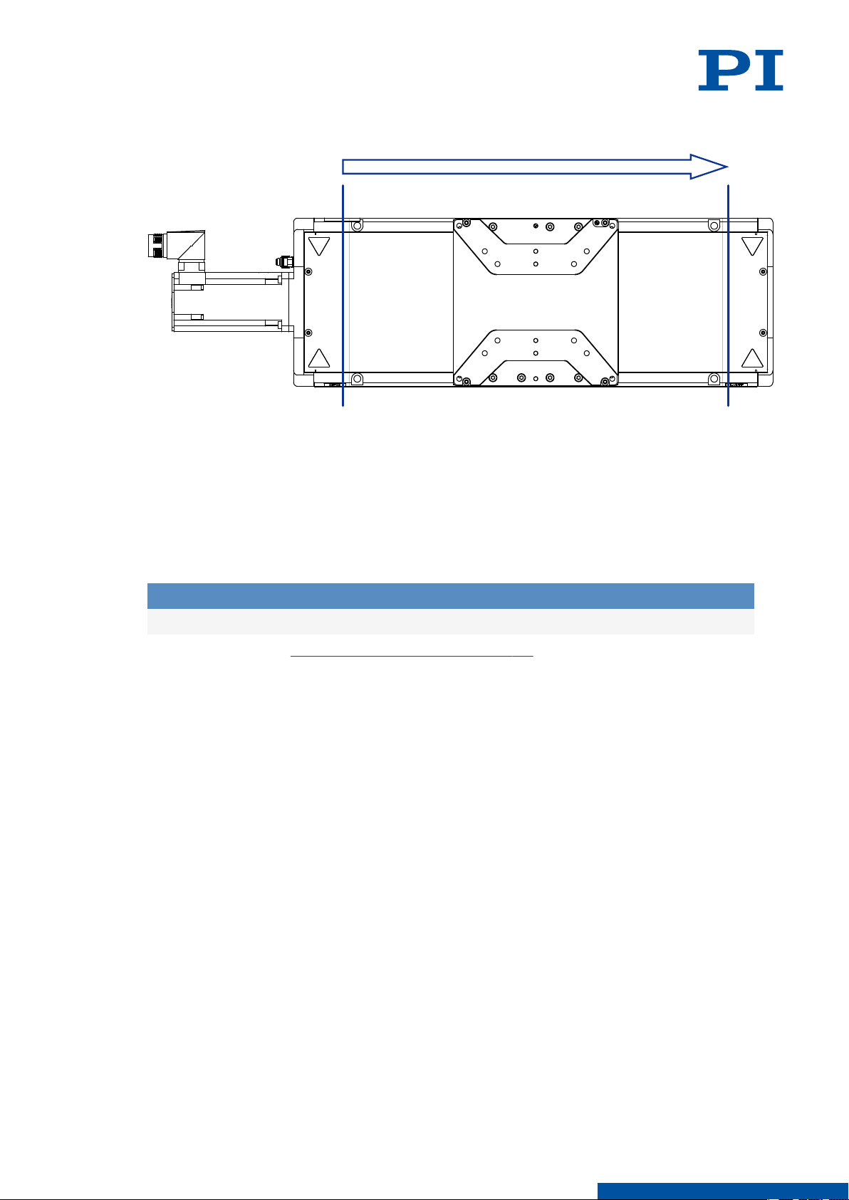
4.5 Direction of Motion
Figure 4: Schematic representation of the direction of motion and limit switches. The exact
position of the limit switches may vary.
L417M0010EN ‒ 7/9/2019
4.6 Suitable Electronics
The L-417.xx9232B must be connected to suitable electronics that supply the necessary
voltage for operating and if required, to evaluate the sensor and limit switch signals. The
following electronics are suitable:
Product number
To order, contact our customer service department (p. 27).
Description
ACS modular controller
13
M O T I O N | P O S I T I O N I N G
Page 14

5 UNPACKING
5 Unpacking
Unpacking the L-417.xx9232B
1. Unpack the L-417.xx9232B with care. Hold the L-417.xx9232B by its base body only.
2. Compare the contents with the scope of delivery according to the contract and the
delivery note.
3. Inspect the contents for signs of damage. If any parts are damaged or missing, contact
our customer service department (p. 27) immediately.
4. If the L-417.xx9232B was supplied with a carrying aid (p. 9): Use the carrying aid to
transport the L-417.xx9232B to the intended place of use.
5. If the L-417.xx9232B was supplied with ESD protective caps on the connectors: Do not
remove the ESD protective caps.
6. Keep all packaging materials in case the product needs to be returned.
L417M0010EN ‒ 7/9/2019
14
M O T I O N | P O S I T I O N I N G
Page 15
6 INSTALLATION L417M0010EN ‒ 7/9/2019
6 Installation
6.1 Mounting the L-417.xx9232B
Overview
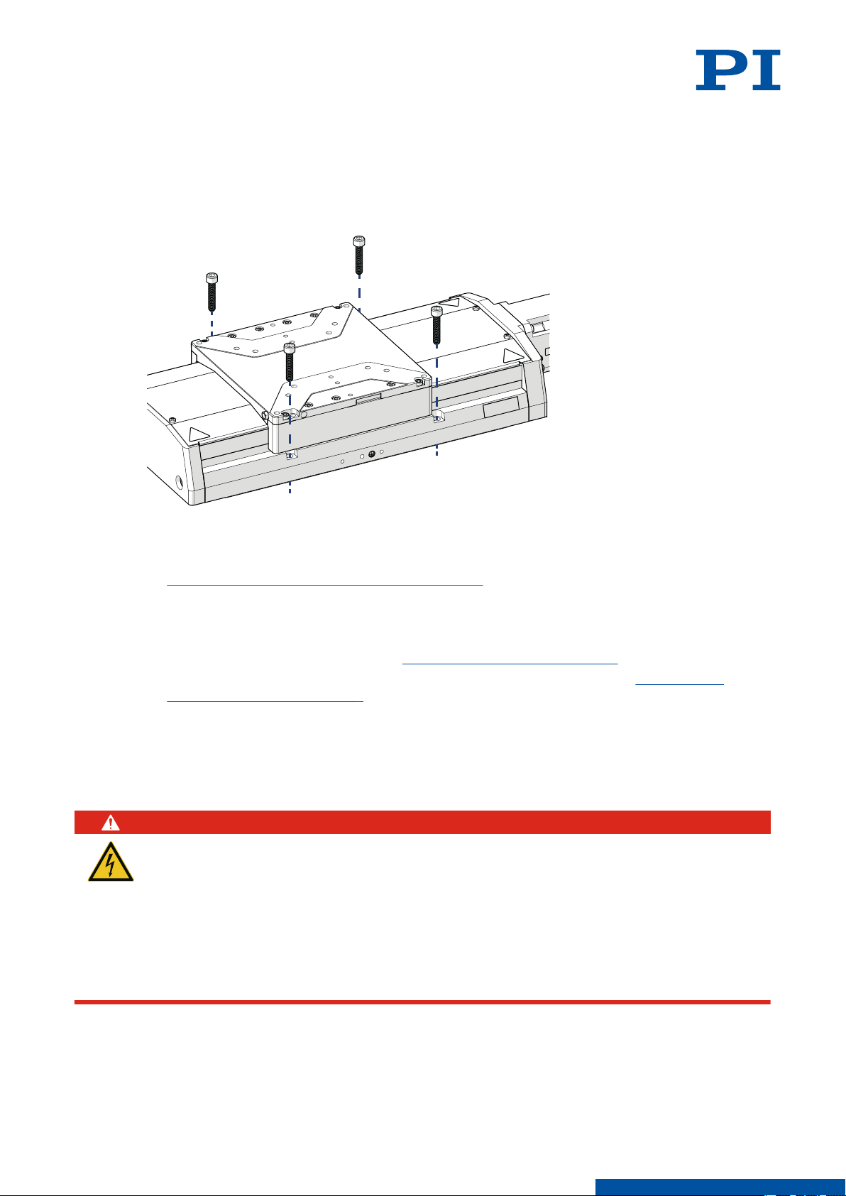
Figure 5: Mounting the L-417.xx9232B onto an underlying surface
Tools and Accessories
■ Screw set for mounting the L-417.xx9232B (p. 9)
■
Suitable screwdriver
Requirements
You have read and understood the general safety instructions (p. 7).
✓
You have provided a suitable surface with the holes necessary for the screws and if
✓
required, locating pins (p. 31).
■
The flatness of the surface is ≤ 2 μm.
■
For applications with large temperature changes: The surface should have the same or
similar thermal expansion properties as the L-417.xx9232B.
You have accounted for the space required to route cables without bending and
✓
according to regulations.
DANGER
Risk of electric shock if the protective earth conductor is not connected!
If the protective earth conductor is missing or not properly connected, risk of dangerous
touch voltages on the L-417.xx9232B in the event of malfunction or failure of the system. If
there are touch voltages, touching the L-417.xx9232B leads to serious injuries or death by
electric shock.
► Connect the L-417.xx9232B to a protective earth conductor before startup.
► Do not remove the protective earth conductor during operation.
► If the protective earth conductor has to be removed temporarily (e.g., for modifications),
reconnect the L-417.xx9232B to the protective earth conductor before restarting.
15
M O T I O N | P O S I T I O N I N G
Page 16
6 INSTALLATION
L417M0010EN ‒ 7/9/2019
CAUTION
Risk of crushing by moving parts!
Risk of minor injuries from crushing between the moving parts of the L-417.xx9232B or the
load and a fixed part or obstacle.
► Use safeguards to protect limbs in areas where they could be caught by moving parts.
► Maintain the safety distances according to DIN EN ISO 13857 when installing protective
structures.
NOTICE
Damage due to collisions!
Collisions can damage the L-417.xx9232B, the load to be moved, and the surroundings.
► Make sure that collisions are not possible between the L-417.xx9232B, the load to be
moved, and the surroundings in the motion range of the L-417.xx9232B.
► Do not place any cables or other objects in areas where they could be caught by moving
parts.
NOTICE
Excessively long screws and locating pins
Screws and locating pins that are inserted too deeply can damage the L-417.xx9232B.
► Pay attention to the depth of the mounting and locating holes (p. 32) in the
L-417.xx9232B.
► Only use screws and locating pins of the correct length for the respective mounting holes.
6.2
Mounting the L-417.xx9232B onto an Underlying Surface
1. If necessary: Insert the locating pins into the corresponding holes in the underlying
surface.
2. Align the L-417.xx9232B on underlying surface so that the corresponding mounting holes
in the L-417.xx9232B and underlying surface in line.
3. Put the L-417.xx9232B onto the underlying surface so that the locating pins can be inserted
into the corresponding locating holes with the L-417.xx9232B.
4. If necessary: Allow access to the mounting holes in the base body of the L-417.xx9232B.
Possible measures:
■ Temporary startup of the L-417.xx9232B (p. 21) and commanding the motion platform
to a suitable position
■ Push the motion platform by hand (p. 24)
5. If necessary, use a flat washer with each screw and insert the screws through the washer
into the mounting hole.
6. Tighten the screws in all accessible mounting holes completely.
Recommended torque: 3 Nm
7. If necessary: Repeat steps 4 to 6 for all concealed mounting holes.
8. Check that the L-417.xx9232B is fixed firmly to the underlying surface.
Connecting the L-417.xx9232B to the Protective Earth Conductor
The L-417.xx9232B must be connected to the protective earth conductor via the drive
connector.
If the load needs to be connected to the protective earth conductor, the L-417.xx9232B's base
body must also be connected to the protective earth conductor. In this case, connect the load
and base body to the protective earth conductor separately.
16
M O T I O N | P O S I T I O N I N G
Page 17
6 INSTALLATION
L417M0010EN ‒ 7/9/2019
Overview
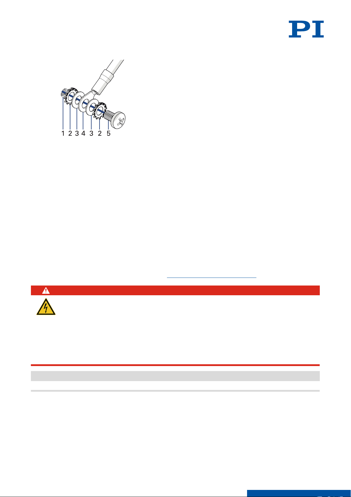
Figure 6: Protective earth connector on the L-417.xx9232B
1. Connector for the protective earth conductor on the L-417.xx9232B, indicated by the
protective earth symbol
2. Safety washer
3. Flat washer
4. Protective earth conductor lug
5. Screw, ISO 7045 M4×8
Tools and Accessories
■
Suitable protective earth conductor:
■
Cable cross section ≥ 0.75 mm
■
Contact resistance <0.1 Ω at 25 A at all connection points relevant for attaching the
2
protective earth conductor
■
Suitable screwdriver
Requirements
You have read and understood the general safety instructions (p. 7).
✓
DANGER
Risk of electric shock if the protective earth conductor is not connected!
If the protective earth conductor is missing or not properly connected, risk of dangerous
touch voltages on the L-417.xx9232B in the event of malfunction or failure of the system. If
there are touch voltages, touching the L-417.xx9232B leads to serious injuries or death by
electric shock.
► Connect the L-417.xx9232B to a protective earth conductor before startup.
► Do not remove the protective earth conductor during operation.
► If the protective earth conductor has to be removed temporarily (e.g., for modifications),
reconnect the L-417.xx9232B to the protective earth conductor before restarting.
Information
► Observe the applicable standards for connecting the protective earth conductor.
17
Connecting the L-417.xx9232B to the Protective Earth Conductor
1. If necessary, attach a suitable cable lug to the protective earth conductor.
2. Attach the cable lug of the protective earth conductor to the protective earth connection
as shown in the illustration of the L-417.xx9232B.
3. Tighten the screw with a torque of 1.2 Nm to 1.5 Nm.
M O T I O N | P O S I T I O N I N G
Page 18
6 INSTALLATION
L417M0010EN ‒ 7/9/2019
4. Make sure that the contact resistance is <0.1 Ω at 25 A at all connection points relevant for
attaching the protective earth conductor.
6.3 Mounting the Load onto the L-417.xx9232B
Overview
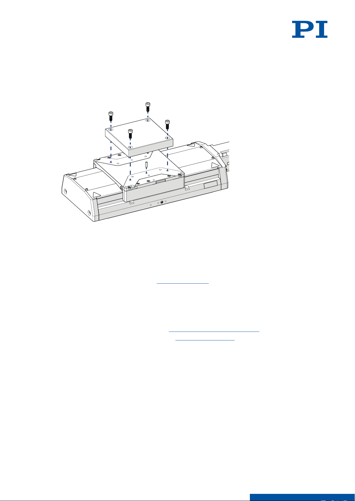
Figure 7: Mounting the load onto the L-417.xx9232B
1. Screws
2. Load
3. Motion platform of the L-417.xx9232B
Tools and Accessories
■
At least 3 screws with suitable dimensions (p. 32)
■ Suitable tool for tightening the screws
■ Optional: 2 suitably dimensioned dowel pins as locating pins for aligning the load on the
L-417.xx9232B
Requirements
You have read and understood the general safety instructions (p. 7).
✓
You have mounted the L-417.xx9232B on the surface (p. 15) properly.
✓
The L-417.xx9232B is not connected to the electronics.
✓
You have prepared the load so that it can be fixed to the mounting holes on the motion
✓
platform:
■
The distance between the center of gravity of the load and the center of the motion
platform is as small as possible in all directions.
■
At least three points are provided for fixing the load on the motion platform.
18
M O T I O N | P O S I T I O N I N G
Page 19
6 INSTALLATION
L417M0010EN ‒ 7/9/2019
NOTICE
Impermissibly high load on the L-417.xx9232B
An impermissible high load impairs the motion of the platform and can damage the
L-417.xx9232B.
► Pay attention to the maximum permissible forces (p. 28) that may act on the motion
platform.
► In the case of multi-axis systems, include the masses of the positioners to be moved
when calculating the load.
Fixing the Load
1. If necessary: Insert the locating pins into the corresponding holes in the motion platform.
2. Align the load on the motion platform so that the mounting holes selected in the motion
platform can be used for mounting the load.
3. Place the load onto the motion platform so that the locating pins are inserted into the
corresponding locating holes in the load.
4. Tighten the screws in all mounting holes.
5. Check that the load is fixed firmly to the motion platform.
6.4 Connecting the L-417.xx9232B
Tools and Accessories
■
Suitable cable set
■
If necessary: Suitable screwdriver for the locking screws of the connectors.
■
Optional: Purge air connector with the following properties:
Pressure: 2 to 6 bar (200 to 600 kPa); purge air hose: Outer diameter 4 mm; air quality as
stated in the specifications (p. 28)
Requirements
You have read and understood the general safety instructions (p. 7).
✓
You have read and understood the user manual for the electronics.
✓
You have installed the electronics properly.
✓
The electronics are switched off.
✓
The L-417.xx9232B is connected to the protective earth conductor (p. 16).
✓
NOTICE
Damage due to incorrect connection of the L-417.xx9232B!
Connecting unsuitable electronics or the wrong cable can lead to damage to the
L-417.xx9232B or the electronics.
► Make sure that the electronics support the drive type of the L-417.xx9232B and has been
configured accordingly.
► Use cables from PI miCos only to connect the L-417.xx9232B to the electronics.
► Pay attention to correct pin assignment (p. 34).
19
Connecting the L-417.xx9232B
1. If necessary: Remove the ESD protective caps from the connectors of the L-417.xx9232B.
2. All of the L-417.xx9232B's connections must be made in the following order:
a) Limit switch connector
b) Optional: Purge air connector
M O T I O N | P O S I T I O N I N G
Page 20
≈7°
6 INSTALLATION
L417M0010EN ‒ 7/9/2019
Permissible pressure: 2 to 6 bar (200 to 600 kPa)
c) Rotary encoder connector
d) Drive connector
3. Secure the connectors against unintentional removal.
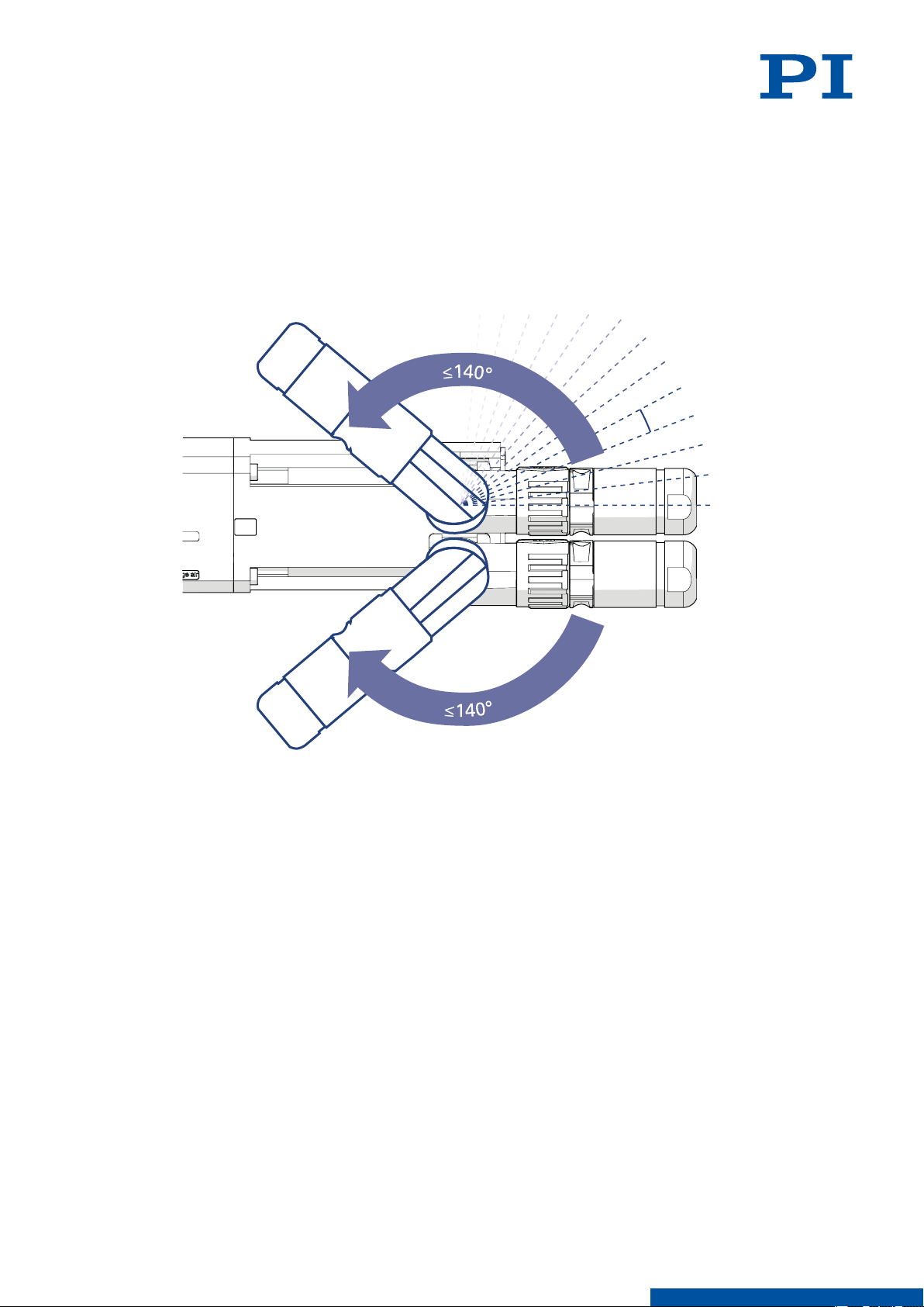
If necessary: Turn the drive and encoder connector carefully to a position suitable for your
installation conditions.
The drive and encoder connector of the L-417.xx9232B can be turned up to 140° (in steps
of approximately 7°).
Figure 8: Rotation range of the L-417.xx9232B's drive/sensor connectors
20
M O T I O N | P O S I T I O N I N G
Page 21
7 STARTUP / OPERATION L417M0010EN ‒ 7/9/2019
7 Startup / Operation
7.1 Starting and Operating the L-417.xx9232B
Requirements
You have read and understood the general safety instructions (p. 7).
✓
For startup with a load or in a multi-axis system: You have installed the L-417.xx9232B
✓
properly (p. 15).
The L-417.xx9232B is connected to the protective earth conductor (p. 16).
✓
If the L-417.xx9232B was delivered with the transport safeguard fitted: You have removed
✓
the transport safeguard (p. 14).
You have read and understood the user manual for the electronics used.
✓
If a digital controller is used: You have read and understood the manual for the PC
✓
software used.
The electronics and if required, the PC software, have been installed (see the user manual
✓
for the electronics).
DANGER
Risk of electric shock if the protective earth conductor is not connected!
If the protective earth conductor is missing or not properly connected, risk of dangerous
touch voltages on the L-417.xx9232B in the event of malfunction or failure of the system. If
there are touch voltages, touching the L-417.xx9232B leads to serious injuries or death by
electric shock.
► Connect the L-417.xx9232B to a protective earth conductor before startup.
► Do not remove the protective earth conductor during operation.
► If the protective earth conductor has to be removed temporarily (e.g., for modifications),
reconnect the L-417.xx9232B to the protective earth conductor before restarting.
CAUTION
Risk of crushing by moving parts!
Risk of minor injuries from crushing between the moving parts of the L-417.xx9232B or the
load and a fixed part or obstacle.
► Use safeguards to protect limbs in areas where they could be caught by moving parts.
► Maintain the safety distances according to DIN EN ISO 13857 when installing protective
structures.
CAUTION
Risk of being caught by moving parts!
Risk of minor injury if hair, jewelry or clothing get caught by moving parts.
► Fit safeguards around all areas with moving parts.
► Never work with the unprotected L-417.xx9232B if you have long hair, loose jewelry or
clothing.
21
CAUTION
Burning due to hot surface!
The drive of the L-417.xx9232B and the surroundings can heat up during operation. Touching
the drive and surrounding parts can result in minor injuries from burning.
► Make sure that the hot drive and the surrounding parts cannot be touched.
M O T I O N | P O S I T I O N I N G
Page 22
7 STARTUP / OPERATION
NOTICE
Operating voltage excessively high or incorrectly connected!
Operating voltages that are too high or incorrectly connected can cause damage to the
L-417.xx9232B.
► Pay attention to the operating voltage range (p. 30), which is specified for the
L-417.xx9232B.
► Pay attention to correct pin assignment (p. 34).
NOTICE
Damage due to collisions!
Collisions can damage the L-417.xx9232B, the load to be moved, and the surroundings.
► Stop the motion immediately if an electronics malfunction occurs.
► If possible, adapt the travel range limits of your mechanical system in the software that
you use for commanding the motion.
NOTICE
Uncontrolled oscillation!
Oscillation can cause irreparable damage to the L-417.xx9232B. Oscillation is indicated by a
humming noise and can be caused by the following:
■ The load and/or dynamics during operation differ considerably from the calibration
settings.
► If you notice oscillation, stop the L-417.xx9232B immediately.
L417M0010EN ‒ 7/9/2019
Starting and Operating the L-417.xx9232B
1. Start the electronics (see the user manual for the electronics).
2. Configure the electronics for the L-417.xx9232B during startup:
■ If you are using a digital controller from PI: In the PC software, select the entry in the
positioner database that matches the L-417.xx9232B exactly.
■ If you are using electronics from another manufacturer: Configure the electronics
according to the parameters of the L-417.xx9232B.
3. Start a few motion cycles for testing purposes (see the user manual for the electronics).
22
M O T I O N | P O S I T I O N I N G
Page 23

8 MAINTENANCE
8 Maintenance
NOTICE
Damage due to improper maintenance!
Improper maintenance can lead to misalignment and failure of the L-417.xx9232B.
► Loosen screws only according to the instructions in this manual or the instructions of our
customer service department (p. 27).
8.1 Maintenance Run
The maintenance run serves the purpose of distributing the existing lubricant.
The following intervals for the maintenance run depend on the operating conditions and the
period of use:
■ After 200 operating hours or at least after one 1 year
■ If the L-417.xx9232B is moved over a small travel range (<40 mm) during industrial
operation: After every 2000 motion cycles
L417M0010EN ‒ 7/9/2019
Performing a Maintenance Run
1. Make sure that collisions between the L-417.xx9232B, the load to be moved, and the
surroundings are not possible over the entire travel range of the L-417.xx9232B. If
necessary, remove the load from the motion platform of the L-417.xx9232B for the
maintenance run.
2. Perform a maintenance run over the entire travel range:
a) Command the L-417.xx9232B to the end of a travel range and from there to the
opposite end of the travel range (see manual for the electronics).
b) If necessary: Command the L-417.xx9232B to a position, where the load can be
mounted onto the motion platform again and mount the load back onto the
L-417.xx9232B (p. 18).
8.2 Relubricating
The L-417.xx9232B is equipped with a grease nipple for relubricating the drive screw. For
continuous industrial use, the lubrication intervals and the lubrication quantity must be
determined individually.
Use Klüber STABURAGS NBU 12/300 KP only as lubrication for the L-417.xx9232B.
If you have any questions on relubricating, contact our customer service department (p. 27).
8.3 Cleaning
23
Requirements
You have disconnected the L-417.xx9232B from the electronics.
✓
Other Materials Required
■ Soft, lint-free cloth
■ Mild cleaning agent or disinfectant
If you have any questions on the auxiliary materials recommended for the L-417.xx9232B,
contact our customer service department (p. 27).
M O T I O N | P O S I T I O N I N G
Page 24

8 MAINTENANCE
L417M0010EN ‒ 7/9/2019
NOTICE
Damage due to unsuitable cleaning agents!
Some cleaning agents can cause rusting on the L-417.xx9232B or dissolve plastics, paints or
adhesives.
► Do not clean with water or acetone.
Cleaning the L-417.xx9232B
1. Dampen the cloth with the cleaning agent or disinfectant.
2. Carefully wipe the surfaces of the L-417.xx9232B.
8.4 Moving the Motion Platform by Hand
It may be necessary to move the motion platform manually,
■ to allow access to the mounting holes in the positioner's base body for the mounting
screws,
■ to move the motion platform away from the mechanical hard stop and make the
L-417.xx9232B operational again.
Requirements
You have disconnected the L-417.xx9232B from the electronics.
✓
Moving the Motion Platform by Hand
1. Apply the supply voltage (p. 37) to the holding brake connectors (p. 34).
➔
The holding brake is released.
2. Exert a steady force on the motion platform to move it.
24
M O T I O N | P O S I T I O N I N G
Page 25
9 TROUBLESHOOTING L417M0010EN ‒ 7/9/2019
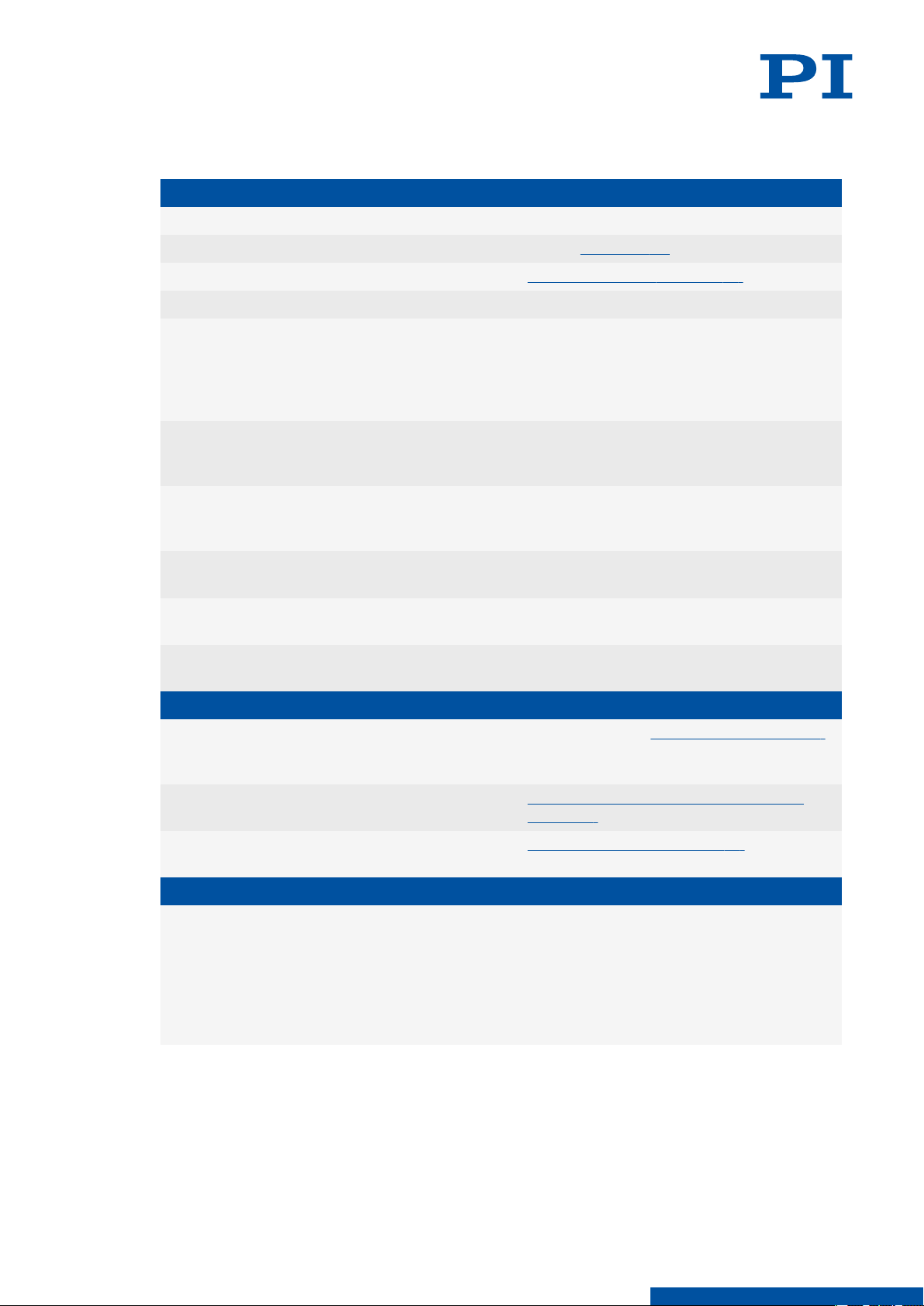
9 Troubleshooting
The positioner does not move
Cable not connected correctly
The electronics or mechanics were replaced
Electronics not connected correctly
Defective electronics
Motion platform has triggered the limit
switch
The positioner was connected to the switched-on electronics
Incorrect configuration
Incorrect command or incorrect syntax
Incorrect axis or channel commanded
Commanded axis is not referenced
► Check the cable connecons.
► Run the startup (p. 21) once again.
► Check all connecng cables (p. 19).
► Check the electronics.
► If you are using a controller from PI: Switch on
the servo mode for the aected axis again in the
PC soware.
► Command the axis to move away from the limit
switch.
► Switch the electronics o and on again or restart
them with the RBT command or with the corre‐
sponding PC soware funcon.
► Check the L‐417.xx9232B's parameter sengs in
the electronics connected and make the appro‐
priate correcons.
►
Send the ERR? command to the PI electronics
connected and check the error code returned.
► Make sure that the electronics use the correct
axis respecvely channel idener.
► Do a reference move for the axis as described in
the user manual for the controller used.
Reduced positioning accuracy
When the L-417.xx9232B is mounted vertically: Load exceeds the holding brake's holding
force
Warped base body
Increased wear due to small motion over a
long period of time
Uncontrolled oscillation
Large changes to the load or the alignment
of the L-417.xx9232B
► Make sure that the brake's holding force (p. 28)
is not exceeded.
► Mount the L‐417.xx9232B onto an even sur‐
face (p. 15).
► Perform a maintenance run (p. 23).
► Switch o the servo control system or the con‐
troller immediately.
► Check whether the servo control parameter set‐
tings correspond to the selected closed‐loop
control mode; see user manual for the controller.
► If necessary, correct the sengs of the servo
control parameters.
25
M O T I O N | P O S I T I O N I N G
Page 26

10 TRANSPORTATION L417M0010EN ‒ 7/9/2019
10 Transportation
Preparing the L-417.xx9232B for Transportation
1. Pay attention to the ambient conditions and classifications (p. 30).
2. Pack the L-417.xx9232B in the original packaging.
3. If the L-417.xx9232B is to be sent, use a stable outer box.
26
M O T I O N | P O S I T I O N I N G
Page 27

11 CUSTOMER SERVICE DEPARTMENT
L417M0010EN ‒ 7/9/2019
11 Customer Service Department
For enquiries and orders, contact your PI miCos representative or send us an email.
If you have any questions concerning your system, provide the following information:
■ Product and serial numbers of all products in the system
■ Firmware version of the controller (if applicable)
■ Version of the driver or the software (if applicable)
■ Operating system on the PC (if applicable)
If possible: Take photographs or make videos of your system that can be sent to our
customer service department if requested.
Customer service address:
Physik Instrumente (PI) GmbH & Co. KG
Auf der Roemerstrasse 1
76228 Karlsruhe
Germany
[email protected]
www.pi.de
27
M O T I O N | P O S I T I O N I N G
Page 28
12 TECHNICAL DATA
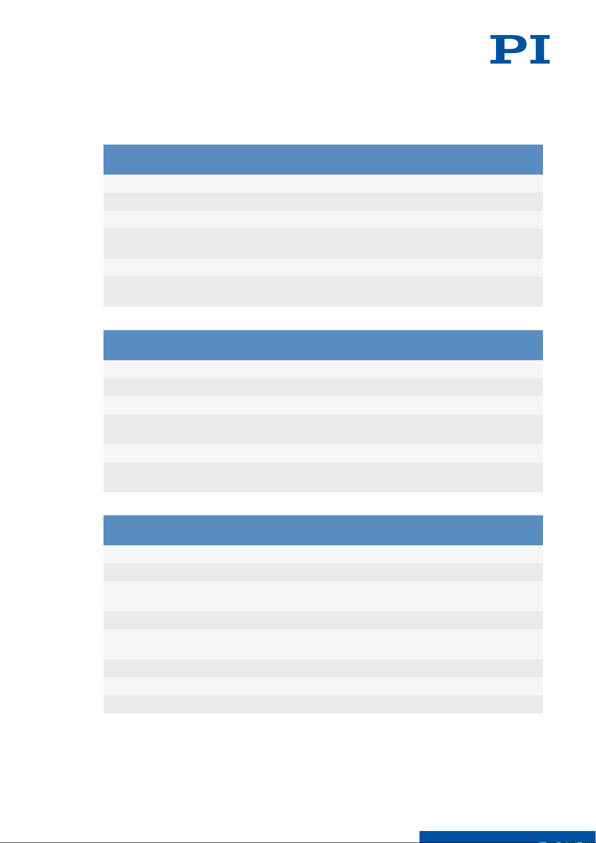
12 Technical Data
12.1 Specifications
Motion L-417.05 L-417.09 L-417.13 L-417.17 Unit Toler-
Active axes X X X X
Travel range 102 204 305 407 mm
Pitch / yaw ±14 ±19 ±29 ±35 μrad max.
L417M0010EN ‒ 7/9/2019
ance
Straightness / flat-
±2.5 ±4 ±6 ±8 μm max.
ness
Velocity, unloaded 300 300 300 300 mm/s max.
Positioning accura-
±6 ±8 ±10 ±12 μm max.
cy, uncalibrated
Motion L-417.21 L-417.25 L-417.33 Unit Toler-
ance
Active axes X X X
Travel range 508 610 813 mm
Pitch / yaw ±40 ±45 ±50 μrad max.
Straightness / flat-
±9 ±10 ±12 μm max.
ness
Velocity, unloaded 300 300 300 mm/s max.
Positioning accura-
±14 ±16 ±18 μm max.
cy, uncalibrated
Encoder options
L-417.xxx232
basic option
Unit Toler-
ance
28
Integrated sensor Incremental rotary encoder
Sensor signal A/B quadrature, RS-422
Sensor resolution 20000 Cts./
rev.
Design resolution 0.25 μm
Minimum incremental mo-
1 μm
tion
Bidirectional repeatability ±1 μm max.
Limit switches Hall effect, N/C contact, 5 V, NPN
Sensor connector M23
M O T I O N | P O S I T I O N I N G
Page 29
12 TECHNICAL DATA
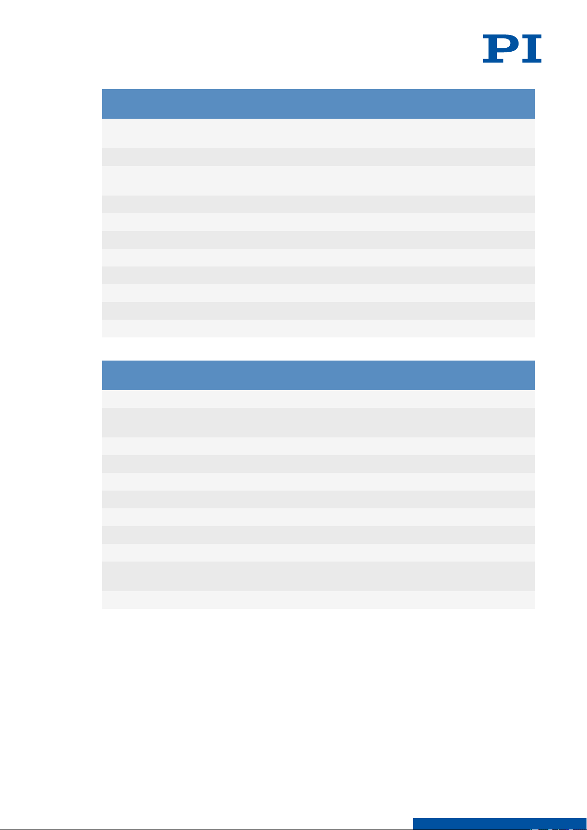
Mechanical properties L-417.xxxxxx L-417.xxxxxxB Unit Toler-
L417M0010EN ‒ 7/9/2019
ance
Guide type Recirculating ball
bearing guide
Recirculating ball
bearing guide
Drive screw type Ball screw Ball screw
Holding brake – Electromagnetic safe-
ty brake
Drive screw pitch 5 5 mm
Push/pull force, power on 700 700 N max.
Holding force, power off – 500 N typ.
Load capacity in Z 450 450 N max.
Permissible lateral force 250 250 N max.
Permissible torque in θX 40 40 N·m max.
Permissible torque in θY 30 30 N·m max.
Permissible torque in θZ 40 40 N·m max.
Drive properties
L-417.xx9 Unit Toler-
ance
Drive type Synchronous Servo Motor
Intermediate circuit voltage,
320 V DC max.
RMS
Peak torque 2.76 N·m typ.
Nominal torque 0.7 N·m typ.
Peak current, RMS 10.9 A typ.
Nominal current, RMS 2.73 A typ.
Torque constant, RMS 0.32 N·m/A typ.
Resistance phase-phase 5.22 Ω typ.
Inductance phase-phase 9.7 mH typ.
Back EMF phase-phase 20.4 V/
max.
kRPM
Number of pole pairs 3
29
M O T I O N | P O S I T I O N I N G
Page 30

12 TECHNICAL DATA
Miscellaneous L-417 Unit Toler-
Operating temperature range 5 to 40 °C
Material Aluminum, black anodized
L417M0010EN ‒ 7/9/2019
ance
stainless steel
Overall mass L-417.05 (102 mm travel range): 9.3
kg ±5 %
L-412.09 (204 mm travel range): 10.8
L-412.13 (305 mm travel range): 12.2
L-412.17 (407 mm travel range): 13.7
L-412.21 (508 mm travel range): 15.1
L-412.25 (610 mm travel range): 16.5
L-417.33 (813 mm travel range). 19.4
Moved mass 2.4 kg ±5 %
MTBF 20000 h
Connection M23 (motor)
M23 (rotary encoder)
Optional connection for linear encoder
Fitting for purge air hose with outside diame-
ter 4 mm
Funnel-type grease nipple for spindle lubri-
cation
Limit switch connection M8 8-pin
Purge air system Operating pressure: 2 to 6 bar (200 to 600
kPa)
Relative humidity: < 70 %
Absolute humidity: < 35 g/m
3
Recommended controllers ACS modular controller
Connecting cables are not in the scope of delivery and must be ordered separately.
12.2 Maximum Ratings
The L-417.xx9232B is designed for the following operating data:
Maximum operating voltage
Maximum Operating Frequency
320 V – 10.9 A
12.3 Ambient Conditions and Classifications
The following ambient conditions and classifications for the L-417.xx9232B must be
observed:
Maximal peak current, RMS
30
M O T I O N | P O S I T I O N I N G
Page 31
A
D
A+D
F
(Energychain
overlap at
hardstop)
X
B
center of travel position
(reference position)
20
6,6/
11,2x8
1/2 LSW (LE1)
1/2 HDS 1/2 HDS
1/2 LSW (LE2)
150
150
4 x
4 H7x7/10
8,5
7,5
83,5 82,5
C
X
166
70
E
75
100
150
75
100
150
2 x
4 H7x7
2 x
4 H7x7
2 x
4 H7x7
4 x M6
8
4 x M6
8
4 x M6
8
BASIS
MODELL
TRAVEL
NOMINAL
LIMITSWITCH TO
LIMITSWITCH
LSW
HARDSTOP TO
HARDSTOP
HDS
A B C D
E
D1 D2
E1 E2 E3
L-417.xxx2xxEx
L-417.xxxx25Ex
L-417.xxxxxxxx
L-417.xxxxxxxxB
L-417.xxxx11E1 L-417.xxxx12E1
L-417.xxxxxxE0
L-417.xxx2xx
L-417.xxxx25E1
L-417.05xxxx
102 (4")
102 - 105
-
109 365 185 150 119,5 153,5 28 44 28,5
L-417.09xxxx
204 (8")
204 - 207
-
214 470 237,5 150, 350 119,5 153,5 28 44 28,5 71 66
L-417.13xxxx
305 (12")
305 - 308
-
314 570 287,5 150, 350 119,5 153,5 28 44 28,5 66 72
L-417.17xxxx
407 (16")
407 - 410
-
419 675 340 150, 350, 550 119,5 153,5 28 44 28,5 69 65
L-417.21xxxx
508 (20")
508 - 511
-
519 775 390 150, 350, 550 119,5 153,5 28 44 28,5 65 70
L-417.25xxxx
610 (24")
610 - 613
-
619 875 440 150, 350, 550, 750 119,5 153,5 28 44 28,5 69 65
L-417.33xxxx
813 (32")
813 - 816
-
824 1080 542,5 150, 350, 550, 750, 950 119,5 153,5 28 44 28,5 68 73
12 TECHNICAL DATA
Area of application For indoor use only
Maximum altitude 2000 m above msl
Relative humidity Max. 80 % for temperatures to 31 °C,
Storage temperature -25 °C to 55 °C
Transport temperature -25 °C to 70 °C
Overvoltage category II
Supply voltage fluctuations Max. ±10 % of the nominal voltage
Protection class I
Degree of pollution 2
Degree of protection according to IEC 60529 IP30
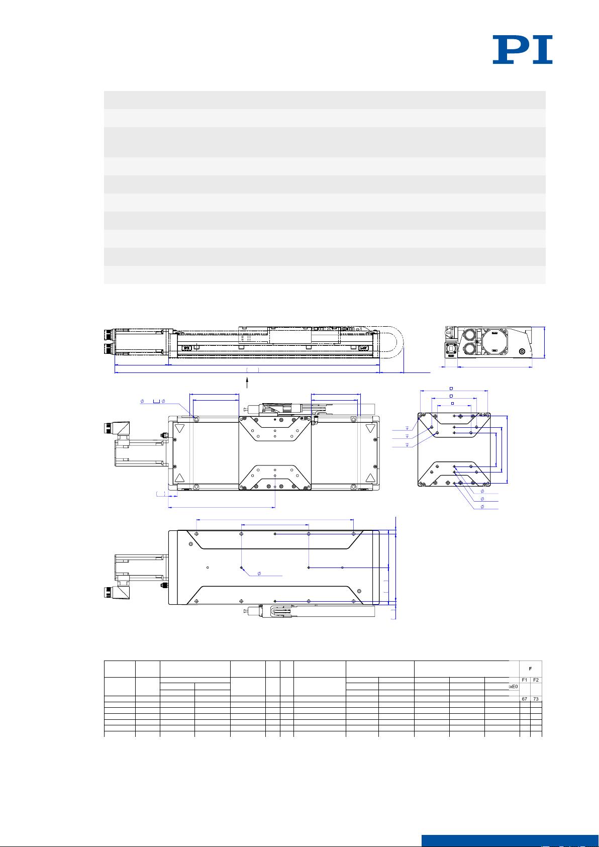
12.4 Dimensions
L417M0010EN ‒ 7/9/2019
linearly decreasing to 50 % at 40 °C
31
Figure 9: Dimensions of the L-417.xx9232B
Dimensions in mm. Note that the decimal places are separated by a comma in the drawings.
M O T I O N | P O S I T I O N I N G
Page 32
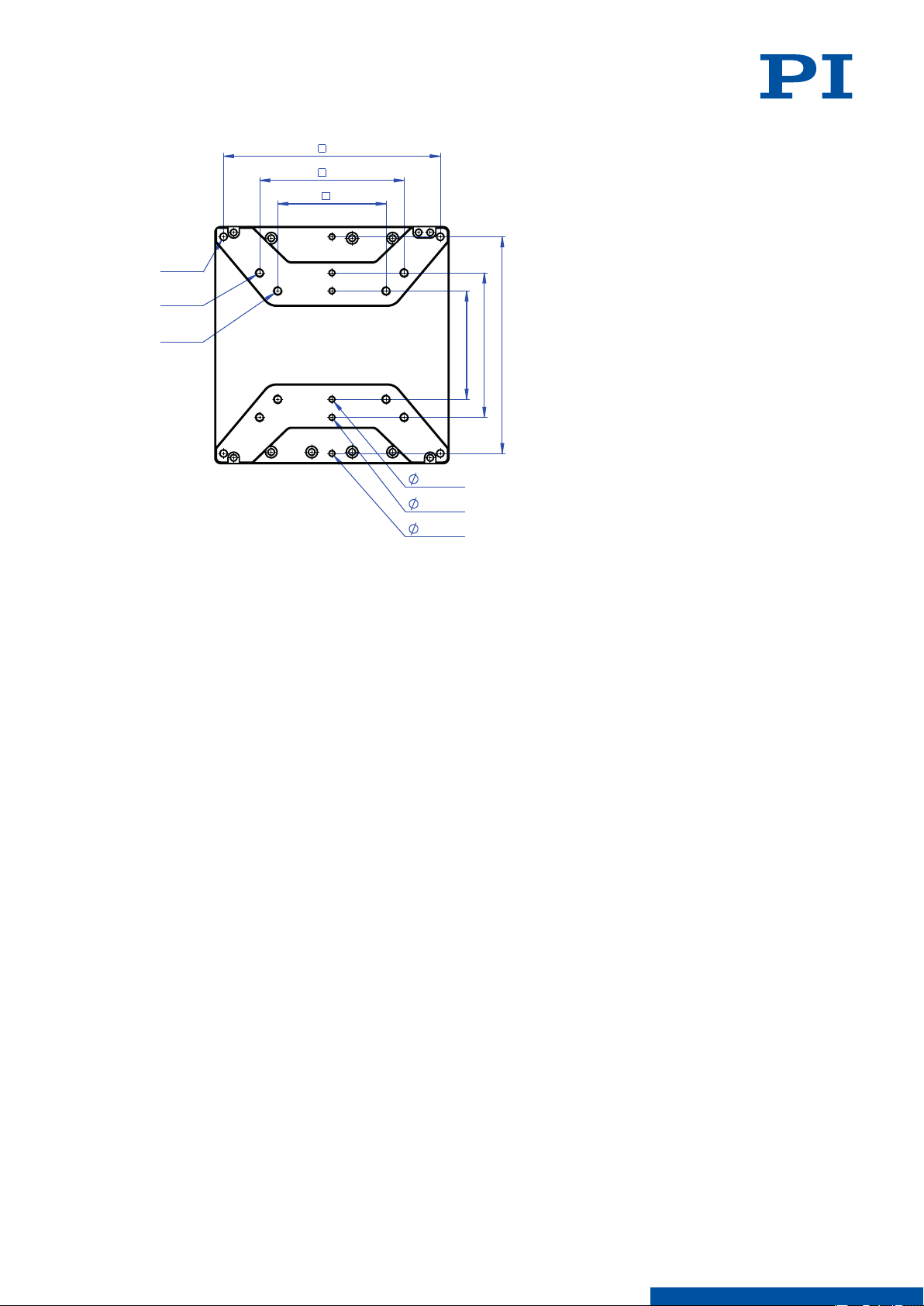
75
100
75
100
150
4 H7x7
4 H7x7
4 H7x7
4 x M6
4 x M6
4 x M6
150
12 TECHNICAL DATA
L417M0010EN ‒ 7/9/2019
Figure 10: Motion platform of the L-417.xx9232B: Dimensions and mounting holes
Dimensions in mm. Note that the decimal places are separated by a comma in the drawings.
32
M O T I O N | P O S I T I O N I N G
Page 33
13 OLD EQUIPMENT DISPOSAL
L417M0010EN ‒ 7/9/2019
13 Old Equipment Disposal
In accordance with EU law, electrical and electronic equipment may not be disposed of in EU
member states via the municipal residual waste.
Dispose of your old equipment according to international, national, and local rules and
regulations.
In order to fulfil the responsibility as the product manufacturer, PI miCos undertakes
environmentally correct disposal of all PI miCos equipment free of charge, if it was made
available to the market after August 13, 2005.
Any old PI miCos equipment can be sent free of charge to the following address:
PI miCos GmbH
Freiburger Strasse 30
79427 Eschbach
Germany
[email protected]
www.pi.de
33
M O T I O N | P O S I T I O N I N G
Page 34
4
A
B
C
D 3
2
1
3
1
2
3
4
5
6
7
8
9
10
11
12
13
14
15
16
17
14 APPENDIX L417M0010EN ‒ 7/9/2019
14 Appendix
14.1 Pin Assignment
14.1.1 Drive Connector
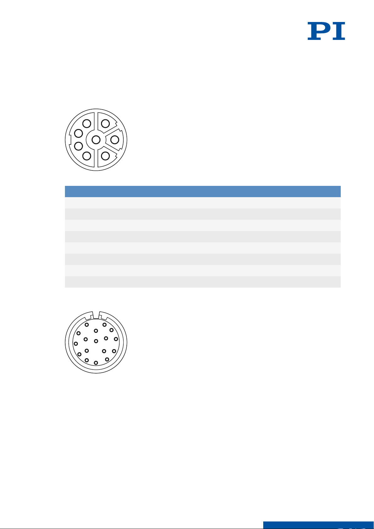
Figure 11: M23 8 (f)
Pin Signal Function
1 U Phase 1
2 PE Protective earth
3 W Phase 3
4 V Phase 2
A BR + Holding brake, +24 V DC
B BR - Holding brake, GND
C nc Not connected
D nc Not connected
14.1.2 Rotary Encoder Connector
34
M O T I O N | P O S I T I O N I N G
Page 35
1
6
7
2
4
3
5
8
14 APPENDIX L417M0010EN ‒ 7/9/2019
Pin Signal Function
1 B Output: Sensor signal B
2 B inv Output: Sensor signal B inverted
3 A Output: Sensor signal A
4 A inv Output: Sensor signal A inverted
5 Z Output: Sensor signal Z
6 Z inv Output: Sensor signal Z inverted
7 GND Ground
8 THERM+ Output: Temperature sensor
9 THERM- Output: Temperature sensor
10 VCC Input: Power supply
11 NC Not connected
12 NC Not connected
13 NC Not connected
14 NC Not connected
15 U Output: Commutation track U
16 V Output: Commutation track V
17 W Output: Commutation track W
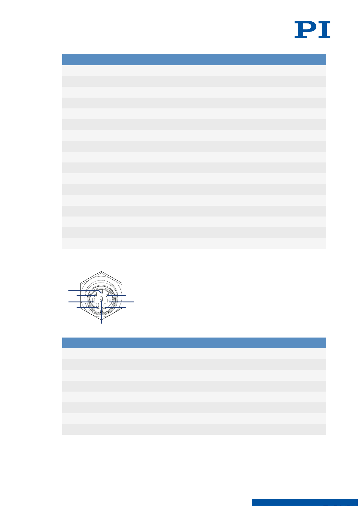
14.1.3 Limit Switch Connector
Pin Signal Function
1 L+5V Input: Power supply, +5 V DC
2 LGND Ground
3 LE2 Output: Positive limit switch
4 LE1 Output: negative limit switch
5 NC Not connected
6 NC Not connected
7 NC Not connected
8 NC Not connected
35
M O T I O N | P O S I T I O N I N G
Page 36
14 APPENDIX
L417M0010EN ‒ 7/9/2019
14.2 Limit Switch Specifications
Type Hall sensor
Supply voltage +5 V
Signal output 0 V / +5 V (TTL level)
Signal logic N/C contact, NPN
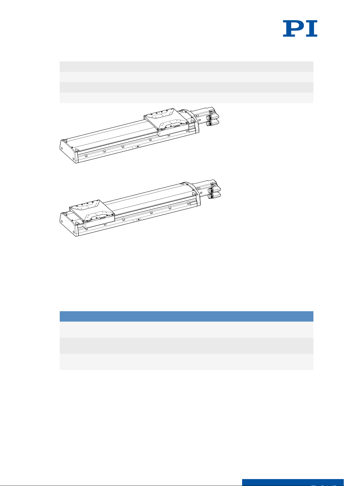
Figure 12: L-417 at the negative limit switch.
Figure 13: L-417 at the positive limit switch.
14.3 PTC Temperature Sensor
The L-417.xx9232B is equipped with a PTC temperature sensor to prevent the motor from
overheating. The electrical resistance of the PTC temperature sensor increases considerably
into the critical temperature range. The controller must cut the power supply to the motor
(switching threshold) when the critical temperature is reached.
Temperature
Up to 150°C
155°C (critical temperature)
More than 155°C
14.4
Commutation Encoder
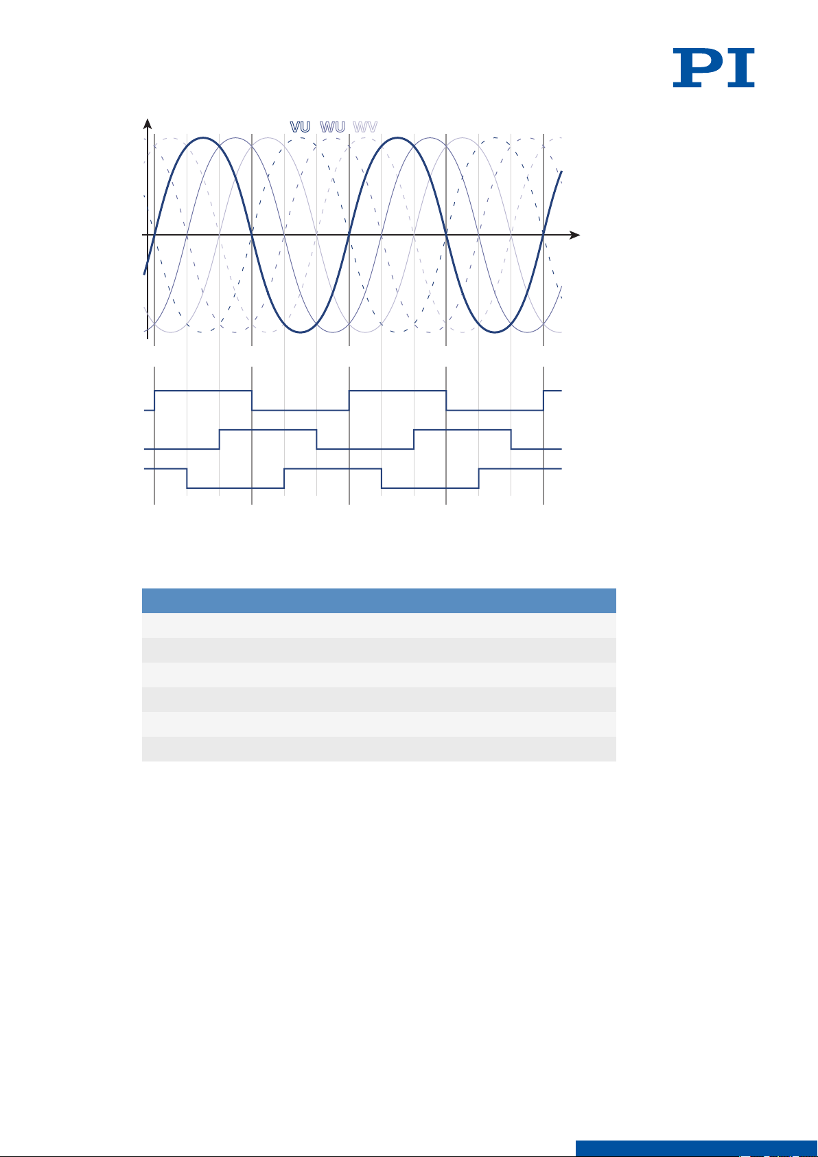
The L-417.xx9232B's motor has a commutation encoder that codes the position of the
magnets in the same way as a Hall effect sensor.
Electrical resistance
< 550 Ω
1000 Ω (switching threshold)
> 1330 Ω
36
M O T I O N | P O S I T I O N I N G
Page 37
0 π 2π 3π 4π
V
W
U
UV VWUW
14 APPENDIX L417M0010EN ‒ 7/9/2019
Figure 14: Motor phases (top) and signal output to the commutation tracks (bottom)
14.5 Holding Brake Specifications
Parameters Value
Supply voltage 24 V
Power requirement 350 mA (min)
Static braking torque 1.42 Nm
Release brake delay 35 ms
Brake delay 36 ms
Linear brake offset 14 μm (max); 6.4 μm (typical)
37
M O T I O N | P O S I T I O N I N G
Page 38

15 EU DECLARATION OF CONFORMITY
L417M0010EN ‒ 7/9/2019
15 EU Declaration of Conformity
An EU Declaration of Conformity was issued for the L-417.xx9232B in accordance with the
following European directives:
■ Low Voltage Directive
■ EMC Directive
■ RoHS Directive
The standards applied for certifying conformity are listed below.
■ Safety (Low Voltage Directive): EN 61010-1
■ EMC: EN 61326-1
■ RoHS: EN 50581
38
M O T I O N | P O S I T I O N I N G
Page 39

Glossary
Backlash
Position error caused by mechanical play in that drivetrain that occurs when changing the
direction. Backlash is caused by mechanical play in drivetrain components such as
gearheads, bearings or by friction in the guides. In contrast to hysteresis, backlash can lead
to instability in position-controlled systems because it causes dead time in the servo loop.
Backlash depends on the temperature, acceleration, load, leadscrew position, positioning
direction, wear etc. Backlash is suppressed by preloading the drivetrain. A position
measuring method that can detect the position of the platform directly, eliminates all errors
in the drivetrain (direct measuring). The data table shows typical measured values. Data for
vacuum versions can differ.
Design Resolution
The theoretical minimum movement that can be made. Design resolution must not be
confused with minimum incremental motion. In indirect position measurement methods,
values for drive screw pitch, gear ratio, motor or sensor/encoder resolution, for example, are
included in the calculation of the resolution. Normally, the design resolution is considerably
below the minimum incremental motion of the mechanics. In direct measurement methods,
the resolution of the sensor system is specified.
L417M0010EN
‒ 7/9/2019
Lateral Force
Also: lateral load capacity
Maximum permissible force orthogonally to the positioning direction. This value is valid
directly for the motion platform and is reduced when the force acts above the platform.
Limit Switch
Each limit switch sends its signal to the controller on a dedicated line. The controller then
interrupts the motion avoiding that the positioner moves until the hard stop and gets
damaged. PI positioners have mechanical, noncontact optical or Hall-effect limit switches.
Load Capacity
Maximum load in the vertical direction when the L-417.xx9232B is mounted horizontally. The
contact point of the load is at the center of the motion platform.
Reference Switch
Many of the positioners are equipped with a direction sensing reference switch positioned
approx. in the middle of the travel range. It is recommended to approach the reference
switch always from the same direction to obtain best position repeatability.
Function: Optical, magnetic
39
Sensor resolution
The sensor can be the critical element of position resolution so it may be necessary to
specify the sensor resolution separately. Rotary encoder: Impulses per screw rotation. Linear
encoder: Smallest motion still detected by the sensor system.
M O T I O N | P O S I T I O N I N G
Page 40

L417M0010EN ‒ 7/9/2019
Travel range
The maximum possible travel range is limited by the length of the drive screw. A possible
gap between the limit switches determines the travel range.
40
M O T I O N | P O S I T I O N I N G
 Loading...