

Page 1
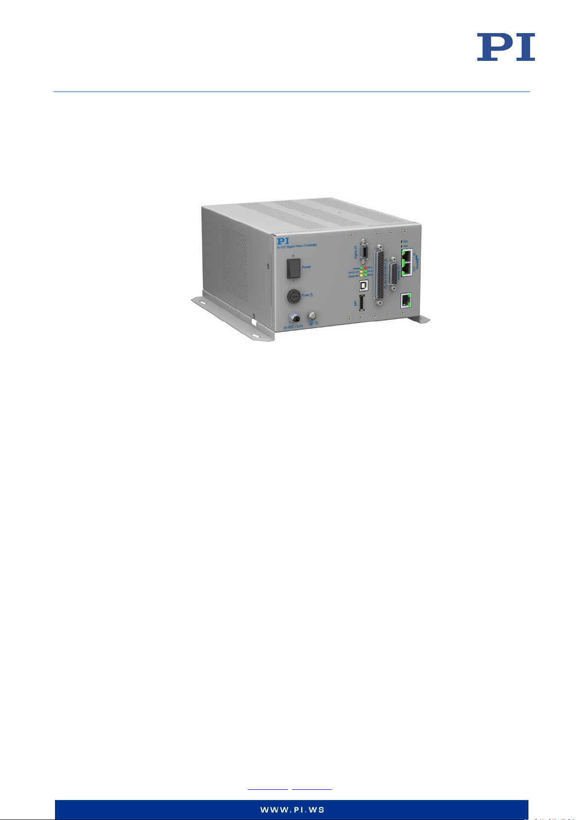
User Manual
E727T0005, valid for E-727
BRO, 2018-03-23
E-727 Digital Multi-Channel Piezo Controller
Physik Instrumente (PI) GmbH & Co. KG, Auf der Roemerstrasse 1, 76228 Karlsruhe, Germany
Phone +49 721 4846-0, Fax +49 721 4846-1019, Email [email protected], www.pi.ws
Page 2
User Manual
E727T0005, valid for E-727
BRO, 2018-03-23
Contents
About this Document 8
Symbols and Typographic Conventions ............................................................................................... 8
Other Applicable Documents ............................................................................................................... 9
Downloading Manuals ....................................................................................................................... 10
Safety 11
Intended Use ...................................................................................................................................... 11
General Safety Instructions ................................................................................................................ 11
Organizational Measures ................................................................................................................... 12
Personnel Qualification ...................................................................................................................... 12
Product Description 13
Model Overview ................................................................................................................................. 13
Product View ...................................................................................................................................... 14
Scope of Delivery................................................................................................................................ 19
Accessories ......................................................................................................................................... 19
Functional Principles .......................................................................................................................... 20
Block Diagrams ....................................................................................................................................... 20
Axes, Channels, Functional Elements ..................................................................................................... 22
Important Components of the Firmware ............................................................................................... 26
Input Signal Processing ........................................................................................................................... 27
Control Value Generation ....................................................................................................................... 30
Output Generation ................................................................................................................................. 34
Control Details.................................................................................................................................... 35
Slew Rate Limitation ............................................................................................................................... 35
Control Algorithms ................................................................................................................................. 35
Feedforward ........................................................................................................................................... 37
Notch Filters ........................................................................................................................................... 37
ID Chip Detection ............................................................................................................................... 39
Overtemp Protection ......................................................................................................................... 39
Overview of PC Software ................................................................................................................... 40
Installation 42
General Notes on Installation ............................................................................................................ 42
Installing the PC Software .................................................................................................................. 42
Performing the Initial Installation ........................................................................................................... 42
Installing Updates ................................................................................................................................... 45
Ensuring Ventilation ........................................................................................................................... 46
Connecting the E-727 to the Protective Earth Conductor ................................................................. 47
Physik Instrumente (PI) GmbH & Co. KG, Auf der Roemerstrasse 1, 76228 Karlsruhe, Germany Page 2 / 228
Phone +49 721 4846-0, Fax +49 721 4846-1019, Email [email protected], www.pi.ws
Page 3

User Manual
E727T0005, valid for E-727
BRO, 2018-03-23
Start-Up 48
General Notes on Start-Up ................................................................................................................. 48
Starting the System in PIMikroMove ................................................................................................. 50
Creating Backup Files for Controller Parameters ............................................................................... 52
Executing Test Motions in Open-Loop Operation .............................................................................. 53
Operation 55
Communication .................................................................................................................................. 55
PC Interfaces ........................................................................................................................................... 55
Additional Interfaces .............................................................................................................................. 55
Communication via the TCP/IP Interface ............................................................................................... 55
Communication via the RS-232 Interface ............................................................................................... 60
Communication via the USB Interface .................................................................................................... 61
AutoZero Procedure ........................................................................................................................... 61
Objective and Prerequisites of AutoZero ............................................................................................... 62
Settings Changed by AutoZero ............................................................................................................... 62
Starting AutoZero via Command Entry ................................................................................................... 62
Starting AutoZero in PIMikroMove ......................................................................................................... 63
Starting AutoZero via EtherCAT Master ................................................................................................. 64
Special Function: Sensor Autoscaling ..................................................................................................... 64
Data Recording ................................................................................................................................... 64
How to Use the Data Recorder ............................................................................................................... 64
Data-Recorder Related Commands and Parameters .............................................................................. 66
External Triggering/Signaling ............................................................................................................. 67
Using Digital Input .................................................................................................................................. 67
Configuring Trigger Output ..................................................................................................................... 68
Using the Analog Input ....................................................................................................................... 79
How to Work with the Analog Input - Overview .................................................................................... 79
Scaling the Analog Input ......................................................................................................................... 81
Use as Control Value Generation Source ............................................................................................... 84
Use as External Sensor Input .................................................................................................................. 85
Deactivation of Unused Analog Input Lines............................................................................................ 86
Analog-Input-Related Commands and Parameters ................................................................................ 86
Using the Analog Output .................................................................................................................... 88
How to Work with the Analog Output - Overview ................................................................................. 88
Use as Position Monitor ......................................................................................................................... 89
Use as Control Signal .............................................................................................................................. 90
Analog-Output-Related Commands and Parameters ............................................................................. 91
Wave Generator ................................................................................................................................. 93
How to Work with the Wave Generator................................................................................................. 93
Wave Generator Examples ..................................................................................................................... 98
Wave-Generator-Related Commands and Parameters ........................................................................ 106
Dynamic Digital Linearization (DDL) ................................................................................................. 108
Working Principle ................................................................................................................................. 108
How to Activate the DDL License .......................................................................................................... 111
How to work with the DDL ................................................................................................................... 112
Physik Instrumente (PI) GmbH & Co. KG, Auf der Roemerstrasse 1, 76228 Karlsruhe, Germany Page 3 / 228
Phone +49 721 4846-0, Fax +49 721 4846-1019, Email [email protected], www.pi.ws
Page 4
User Manual
E727T0005, valid for E-727
BRO, 2018-03-23
DDL-Related Commands and Parameters ............................................................................................ 114
Controller Macros ............................................................................................................................ 115
Commands for Macros ......................................................................................................................... 115
Working with Macros ........................................................................................................................... 117
Variables .......................................................................................................................................... 124
Adjustment Procedures 125
ID-Chip Support / Stage Replacement ............................................................................................. 125
"Simple" Replacement .......................................................................................................................... 125
Upgrade or Repair of Stages ................................................................................................................. 126
Replacement of Tip/Tilt Platforms with Differential Drive ................................................................... 126
Servo-Controller Dynamic Tuning .................................................................................................... 128
Parameters to be Modified .................................................................................................................. 128
General Notes on Servo-Controller Dynamic Tuning............................................................................ 128
Adjusting the Notch Filter(s) in Open-Loop Operation ......................................................................... 130
Checking and Optimizing the Servo-Control Parameters ..................................................................... 134
SPI Interface 138
Definition of Terms .......................................................................................................................... 138
Overview .......................................................................................................................................... 138
Configuration Parameters ................................................................................................................ 139
Configuring the Usage of Received Data .............................................................................................. 139
Configuring the Limits for Position Scaling ........................................................................................... 139
Data Packet Definition ..................................................................................................................... 140
Data Frame ........................................................................................................................................... 140
CRC-16 Generation ............................................................................................................................... 140
Transport Layer ................................................................................................................................ 141
Data Segment 1 .................................................................................................................................... 141
Data Segment 2 .................................................................................................................................... 141
Connection Lost .................................................................................................................................... 144
Transport Layer Flow Charts ............................................................................................................ 144
Nomenclature ....................................................................................................................................... 144
Sender Flow Charts ............................................................................................................................... 145
Receiver Flow Charts ............................................................................................................................ 147
Application Layer.............................................................................................................................. 149
Axis Position Data Transfer ................................................................................................................... 149
OnTarget-Flag Transfer ......................................................................................................................... 150
Transfer of Servo-Mode Changing Commands ..................................................................................... 150
GCS Command Transfer ........................................................................................................................ 150
Data Transmission via SPI................................................................................................................. 152
Data Line Definition .............................................................................................................................. 152
Packet Transmission ............................................................................................................................. 152
LDAT: Latch Data Output / Load Data Input ......................................................................................... 153
CS: Data Word Latch ............................................................................................................................. 153
SCLK: Serial Data Clock from Host ........................................................................................................ 153
Physik Instrumente (PI) GmbH & Co. KG, Auf der Roemerstrasse 1, 76228 Karlsruhe, Germany Page 4 / 228
Phone +49 721 4846-0, Fax +49 721 4846-1019, Email [email protected], www.pi.ws
Page 5
User Manual
E727T0005, valid for E-727
BRO, 2018-03-23
DCLK: Data Output Clock ...................................................................................................................... 154
Serial Transmission ............................................................................................................................... 154
Physical Layer ................................................................................................................................... 155
Transmission Lines ................................................................................................................................ 155
Timing Diagrams ................................................................................................................................... 155
EtherCAT Interface 158
Overview .......................................................................................................................................... 158
Configuring the EtherCAT Network .................................................................................................. 159
Connecting the EtherCAT Master ......................................................................................................... 159
Configuring the EtherCAT Master ......................................................................................................... 159
Scaling Position and Velocity Values .................................................................................................... 159
EtherCAT Communication ................................................................................................................ 160
Communication State Machine ............................................................................................................ 160
Communication Details with E-727 ...................................................................................................... 161
Controlling the Axes ......................................................................................................................... 162
Necessary Adjustments ........................................................................................................................ 162
Cycle Time............................................................................................................................................. 162
Object Dictionary .................................................................................................................................. 162
Drive State Machine ............................................................................................................................. 163
Control Word ........................................................................................................................................ 165
Status Word .......................................................................................................................................... 166
Modes of Operation ............................................................................................................................. 167
Error Handling....................................................................................................................................... 167
Homing Mode .................................................................................................................................. 167
Profile Position Mode....................................................................................................................... 168
Cyclic Synchronous Position Mode .................................................................................................. 171
GCS Commands 172
Notation .......................................................................................................................................... 172
GCS Syntax for Syntax Version 2.0 ................................................................................................... 172
Limitations for GCS Commands........................................................................................................ 174
Command Overview ......................................................................................................................... 175
Parameters 179
Settings of the E-727 ........................................................................................................................ 179
Parameter Handling ......................................................................................................................... 179
General Commands for Parameters ..................................................................................................... 181
Commands for Fast Access to Individual Parameters........................................................................... 181
Parameter Overview ........................................................................................................................ 183
Physik Instrumente (PI) GmbH & Co. KG, Auf der Roemerstrasse 1, 76228 Karlsruhe, Germany Page 5 / 228
Phone +49 721 4846-0, Fax +49 721 4846-1019, Email [email protected], www.pi.ws
Page 6
User Manual
E727T0005, valid for E-727
BRO, 2018-03-23
Maintenance 198
Updating Firmware .......................................................................................................................... 198
Cleaning the E-727 ........................................................................................................................... 205
Changing the Fuse ............................................................................................................................ 205
Troubleshooting 206
Technical Data 210
Specifications ................................................................................................................................... 210
Data Table ............................................................................................................................................. 210
Maximum Ratings ................................................................................................................................. 212
Ambient Conditions and Classifications ............................................................................................... 212
Operating Limits ............................................................................................................................... 213
System Requirements ...................................................................................................................... 215
Dimensions ....................................................................................................................................... 216
Pin Assignment ................................................................................................................................. 218
E-727 for Capacitive Sensors: Socket for Piezo Stages ......................................................................... 218
E-727 for Piezoresistive Sensors and SGS: Socket for Piezo Stages ...................................................... 219
Digital I/O ............................................................................................................................................. 220
E-727.xxxA, E-727.xxxAx: Analog I/O .................................................................................................... 221
E-727.IO3x Analog Input Cable ............................................................................................................. 223
E-727.IO8 Adapter Cable for Analog I/O ............................................................................................... 224
RS-232 ............................................................................................................................................. 225
Power Supply 24 V ................................................................................................................................ 225
SPI Interface .......................................................................................................................................... 226
Customer Service 227
Old Equipment Disposal 227
EC Declaration of Conformity 228
Physik Instrumente (PI) GmbH & Co. KG, Auf der Roemerstrasse 1, 76228 Karlsruhe, Germany Page 6 / 228
Phone +49 721 4846-0, Fax +49 721 4846-1019, Email [email protected], www.pi.ws
Page 7

User Manual
E727T0005, valid for E-727
BRO, 2018-03-23
The following company names and brands are registered trademarks of Physik Instrumente (PI)
GmbH & Co. KG:
PI®, NanoCube®, PICMA®, PILine®, NEXLINE®, PiezoWalk®, NEXACT®, Picoactuator®, PInano®,
PIMag®, Q-Motion®
Notes on third-party brand names and trademarks:
Microsoft® and Windows® are either registered trademarks or trademarks of Microsoft
Corporation in the United States and / or other countries.
EtherCAT® is a registered trademark of and licensed by Beckhoff Automation GmbH.
LabVIEW, National Instruments and NI are trademarks of National Instruments. Neither PI, nor any
software programs or other goods or services offered by PI, are affiliated with, endorsed by, or
sponsored by National Instruments.
The following designations are registered company names, trademarks or registered trademarks of
their respective owners:
Linux, MATLAB, MathWorks
The patents owned by PI can be found in our patent list
The software products provided by PI are subject to the General Software License Terms of Physik
Instrumente (PI) GmbH & Co. KG and may contain and/or use third-party software components.
Further information can be found in the General Software License Terms and in the
Software Notes on our website.
© 2018 Physik Instrumente (PI) GmbH & Co. KG, Karlsruhe, Germany. The text, photographs, and
drawings in this manual are protected by copyright. With regard thereto, Physik Instrumente (PI)
GmbH & Co. KG retains all the rights. The use of any text, images and drawings is permitted only in
part and only when indicating the source.
Original instructions
First printing: 2018-02-23
Document number: E727T0005, BRo
Subject to change without notice. This manual is superseded by any new release. The latest
respective release is available for download on our website (http://www.pi.ws).
.
Third-Party
Physik Instrumente (PI) GmbH & Co. KG, Auf der Roemerstrasse 1, 76228 Karlsruhe, Germany Page 7 / 228
Phone +49 721 4846-0, Fax +49 721 4846-1019, Email [email protected], www.pi.ws
Page 8
User Manual
Danger
Notice
1.
2.
Action consisting of several steps whose sequential order must be observed
Action consisting of one or several steps whose sequential order is irrelevant
List item
SVO?
Device S/N
Parameter name (example: parameter where the serial number is stored)
Start > Settings
Menu path in the PC software (example: to open the menu, the Start and Settings
5
Value that must be entered or selected via the PC software
E727T0005, valid for E-727
BRO, 2018-03-23
About this Document
This user manual contains information on the intended use of the E-727.
It assumes that the reader has a fundamental understanding of basic servo systems as well as
motion control concepts and applicable safety procedures.
The latest versions of user manuals and Technical Notes are available for download on our website
(www.pi.ws).
Symbols and Typographic Conventions
The following symbols and markings are used in this user manual:
CAUTION
Dangerous situation
If not avoided, the dangerous situation will result in minor injury.
Actions to take to avoid the situation.
NOTICE
Dangerous situation
If not avoided, the dangerous situation will result in damage to the equipment.
Actions to take to avoid the situation.
Symbol Meaning
p. 5 Cross-reference to page 5
RS-232
If not avoided, the hazardous situation will result in death or serious injury.
If not avoided, the dangerous situation will result in damage to the equipment.
Command line or command from PI's General Command Set (GCS) (example:
command to get the servo mode)
Operating element labeling on the product (example: socket of the RS-232
interface)
buttons must be clicked in succession)
Physik Instrumente (PI) GmbH & Co. KG, Auf der Roemerstrasse 1, 76228 Karlsruhe, Germany Page 8 / 228
Phone +49 721 4846-0, Fax +49 721 4846-1019, Email [email protected], www.pi.ws
Page 9
User Manual
PI General Command Set (GCS)
PZ281E GCS Commands Manual for E-727
GCS Data
SM146E Software Manual
Analog Controller GCS Driver Set for use with NI
PZ181E Software Manual
PI MATLAB Driver GCS 2.0
SM155E Software Manual
PI Frequency Generator Tool
PI Update Finder
A000T0028 Technical Note
Description
Document
EtherCAT Implementation Directive for CiA402 Drive
ETG.6010 D (R) V1.1.0
Implementing a PI Controller in TwinCAT 3.1 for a
A000T0071 Technical Note
E727T0005, valid for E-727
BRO, 2018-03-23
Other Applicable Documents
Additional documentation for the E-727:
Description Document
Documentation for the available PC software:
Description Document
E-727 GCS Driver Set for use with NI LabVIEW
software
LabVIEW software
Merge Tool for use with driver sets for NI LabVIEW
software
PI GCS 2 DLL SM151E Software Manual
PIMikroMove SM148E Software Manual
Available in PIMikroMove
Updating PI Software A000T0032 Technical Note
Basic information on EtherCAT networks and the CiA402 drive profile:
Adjustable speed electrical power drive systems Part 7-201: Generic interface and use of profiles for
power drive systems - Profile type 1 specification
Adjustable speed electrical power drive systems Part 7-301: Generic interface and use of profiles for
power drive systems - Mapping of profile type 1 to
network technologies
PZ260E Software Manual
SM154E Software Manual
A000T0057 Technical Note
IEC 61800-7-201:2015
IEC 61800-7-301:2015
Profile: Directive for using IEC 61800-7-201 within
EtherCAT-based servo drives
Documentation of EtherCAT samples on the E-727 CD:
Description Document
Single-Axis Motion
Physik Instrumente (PI) GmbH & Co. KG, Auf der Roemerstrasse 1, 76228 Karlsruhe, Germany Page 9 / 228
Phone +49 721 4846-0, Fax +49 721 4846-1019, Email [email protected], www.pi.ws
Page 10
User Manual
If a manual is missing or problems occur with downloading:
E727T0005, valid for E-727
BRO, 2018-03-23
Downloading Manuals
INFORMATION
Contact our customer service department (p. 227).
INFORMATION
For products that are supplied with software (CD in the scope of delivery), access to the manuals
is protected by a password. Protected contents are only displayed on the website after entering
the access data.
You need the CD of the product to obtain the access data.
For products with CD: Obtain access data
1. Insert the product CD into the PC drive.
2. Switch to the Manuals directory on the CD.
3. In the Manuals directory, open the Release News (file including releasenews in the file name).
4. Find the access data for the download of protected contents in the section "User login for
software download" in the Release News. Possibilities for the provision:
− Link to a registration page for request of access data
− Direct display of user name and password
5. If the access data have to be requested via a registration page:
a) Follow the link in the Release News.
b) Enter the information required for registration.
c) Click Show login data.
d) Find the user name and the password in the browser window.
Downloading Manuals
If you have requested via registration page the access data for protected contents (see above):
Click the links on the registration page to move to the contents for your product, and log in
there with the access data.
General procedure:
1. Open the website www.pi.ws.
2. If access to the manuals is protected by a password:
a) Click Login.
b) Log in with the user name and password.
3. Click Search.
4. Enter the product code up to the period (“E-727”) into the search field.
5. Click Start search or press the Enter key.
6. Open the corresponding product detail page in the list of search results:
a) If necessary: Scroll down the list.
Physik Instrumente (PI) GmbH & Co. KG, Auf der Roemerstrasse 1, 76228 Karlsruhe, Germany Page 10 / 228
Phone +49 721 4846-0, Fax +49 721 4846-1019, Email [email protected], www.pi.ws
Page 11

User Manual
E727T0005, valid for E-727
BRO, 2018-03-23
b) If necessary: Click Load more results at the end of the list.
c) Click the corresponding product in the list.
7. Scroll down to the Downloads section on the product detail page.
The manuals are displayed under Documentation.
8. Click the desired manual and save it to the hard disk of your PC or to a data storage medium.
Safety
Intended Use
The E-727 is a laboratory device according to DIN EN 61010-1. It is intended to be used in interior
spaces and in an environment which is free of dirt, oil and lubricants.
The E-727 is designed and intended for driving capacitive loads (e. g. piezo ceramic actuators).
The E-727 must not be used for purposes other than those named in this user manual. In
particular, the E-727 must not be used to drive ohmic or inductive loads.
The E-727 can be used for static as well as dynamic applications.
Depending on the model, capacitive sensors or strain gauge sensors or piezoresistive sensors
(semiconductor strain gauge sensors) must be used for closed-loop operation. PI stages intended
for closed-loop operation already have the corresponding sensors. Other sensors can only be used
with PI approval.
General Safety Instructions
The E-727 is built according to state-of-the-art technology and recognized safety standards.
Improper use can result in personal injury and/or damage to the E-727.
Only use the E-727 for its intended purpose, and only use it if it is in a good working order.
Read the user documentation (user manuals, Technical Notes).
Immediately eliminate any faults and malfunctions that are likely to affect safety.
The operator is responsible for the correct installation and operation of the E-727.
Install the E-727 near the power source so that the power plug can be quickly and easily
disconnected from the mains.
Use the supplied components (adapter) to connect the E-727 to the power source.
If one of the supplied components for connecting to the power source has to be replaced,
use a sufficiently dimensioned component.
Only use cables and connections that meet local safety regulations.
Physik Instrumente (PI) GmbH & Co. KG, Auf der Roemerstrasse 1, 76228 Karlsruhe, Germany Page 11 / 228
Phone +49 721 4846-0, Fax +49 721 4846-1019, Email [email protected], www.pi.ws
Page 12
User Manual
E727T0005, valid for E-727
BRO, 2018-03-23
If a protective earth conductor is not or not properly connected, dangerous touch voltages can
occur on the E-727 in the case of malfunction or failure of the system. If touch voltages exist,
touching the E-727 can result in serious injury or death from electric shock.
Connect the E-727 to a protective earth conductor before start-up (p. 47).
Do not remove the protective earth conductor during operation.
If the protective earth conductor has to be removed temporarily (e. g. in the case of
modifications), reconnect the E-727 to the protective earth conductor before starting it up
again.
Organizational Measures
User documentation (user manual, Technical Notes):
Always keep this user documentation available by the E-727.
The latest versions of the user documentation are available from PI.
Add all information given by the manufacturer to the user documentation, for example
supplements or Technical Notes.
If you pass the E-727 on to other users, also turn over the user documentation as well as
other relevant information provided by the manufacturer.
Only use the device on the basis of the complete user documentation. Missing information
due to an incomplete user documentation can result in serious or fatal injury as well as
property damage.
Only install and operate the E-727 after having read and understood this user manual.
Personnel Qualification
The E-727 may only be installed, started up, operated, maintained and cleaned by authorized and
qualified staff.
Physik Instrumente (PI) GmbH & Co. KG, Auf der Roemerstrasse 1, 76228 Karlsruhe, Germany Page 12 / 228
Phone +49 721 4846-0, Fax +49 721 4846-1019, Email [email protected], www.pi.ws
Page 13
User Manual
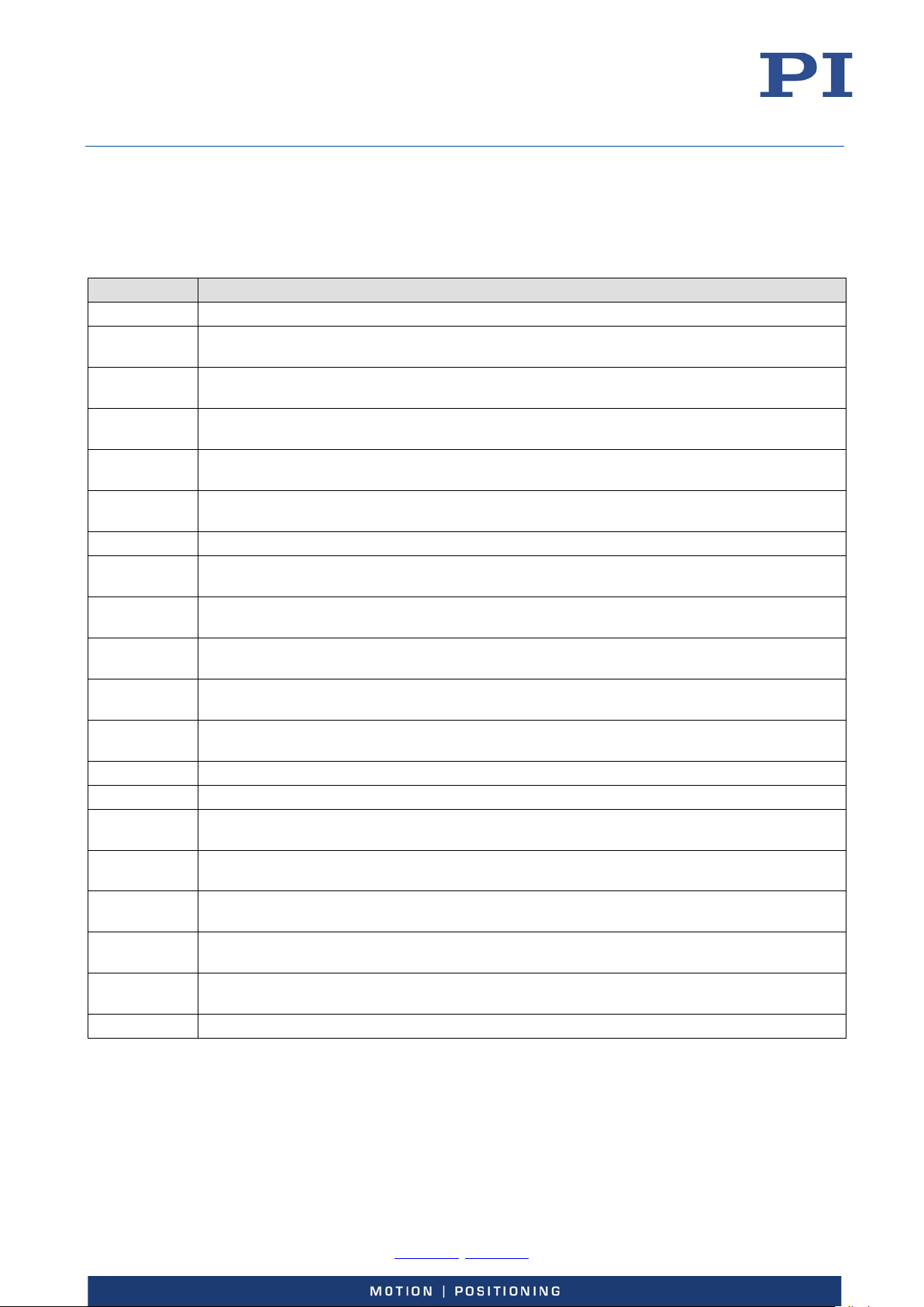
E-727.3CD
Digital multi-channel piezo controller, 3 axes, -30 to 130 V, capacitive sensors, Sub-D 25W3 socket
E-727.3CDP
E-727.3CDF
Digital multi-channel piezo controller, 3 axes, -30 to 130 V, capacitive sensors, Sub-D 25W3 socket,
E-727.3SDF
E-727.4SD
Digital multi-channel piezo controller, 4 axes, -30 to 130 V, strain gauge sensors, Sub-D 37 socket
E727T0005, valid for E-727
BRO, 2018-03-23
Product Description
Model Overview
Model Name
E-727.3CDA
E-727.3CDAP
E-727.3CDAF
E-727.3RD Digital multi-channel piezo controller, 3 axes, -30 to 130 V, piezoresistive sensors, Sub-D 37 socket
E-727.3RDA
E-727.3RDP
E-727.3RDAP
E-727.3RDF
E-727.3RDAF
E-727.4RD Digital multi-channel piezo controller, 4 axes, -30 to 130 V, piezoresistive sensors, Sub-D 37 socket
E-727.3SD Digital multi-channel piezo controller, 3 axes, -30 to 130 V, strain gauge sensors, Sub-D 37 socket
E-727.3SDA
E-727.3SDP
E-727.3SDAP
E-727.3SDAF
Digital multi-channel piezo controller, 3 axes, -30 to 130 V, capacitive sensors, Sub-D 25W3 socket,
analog inputs
Digital multi-channel piezo controller, 3 axes, -30 to 130 V, capacitive sensors, Sub-D 25W3 socket,
1,5 A peak output current
Digital multi-channel piezo controller, 3 axes, -30 to 130 V, capacitive sensors, Sub-D 25W3 socket,
1,5 A peak output current, analog inputs
EtherCAT interface
Digital multi-channel piezo controller, 3 axes, -30 to 130 V, capacitive sensors, Sub-D 25W3 socket,
EtherCAT interface, analog inputs
Digital multi-channel piezo controller, 3 axes, -30 to 130 V, piezoresistive sensors, Sub-D 37 socket,
analog inputs
Digital multi-channel piezo controller, 3 axes, -30 to 130 V, piezoresistive sensors, Sub-D 37 socket,
1,5 A peak output current
Digital multi-channel piezo controller, 3 axes, -30 to 130 V, piezoresistive sensors, Sub-D 37 socket,
1,5 A peak output current, analog inputs
Digital multi-channel piezo controller, 3 axes, -30 to 130 V, piezoresistive sensors, Sub-D 37 socket,
EtherCAT interface
Digital multi-channel piezo controller, 3 axes, -30 to 130 V, piezoresistive sensors, Sub-D 37 socket,
EtherCAT interface, analog inputs
Digital multi-channel piezo controller, 3 axes, -30 to 130 V, strain gauge sensors, Sub-D 37 socket,
analog inputs
Digital multi-channel piezo controller, 3 axes, -30 to 130 V, strain gauge sensors, Sub-D 37 socket,
1,5 A peak output current
Digital multi-channel piezo controller, 3 axes, -30 to 130 V, strain gauge sensors, Sub-D 37 socket,
1,5 A peak output current, analog inputs
Digital multi-channel piezo controller, 3 axes, -30 to 130 V, strain gauge sensors, Sub-D 37 socket,
EtherCAT interface
Digital multi-channel piezo controller, 3 axes, -30 to 130 V, strain gauge sensors, Sub-D 37 socket,
EtherCAT interface, analog inputs
Physik Instrumente (PI) GmbH & Co. KG, Auf der Roemerstrasse 1, 76228 Karlsruhe, Germany Page 13 / 228
Phone +49 721 4846-0, Fax +49 721 4846-1019, Email [email protected], www.pi.ws
Page 14
User Manual
E727T0005, valid for E-727
BRO, 2018-03-23
Product View
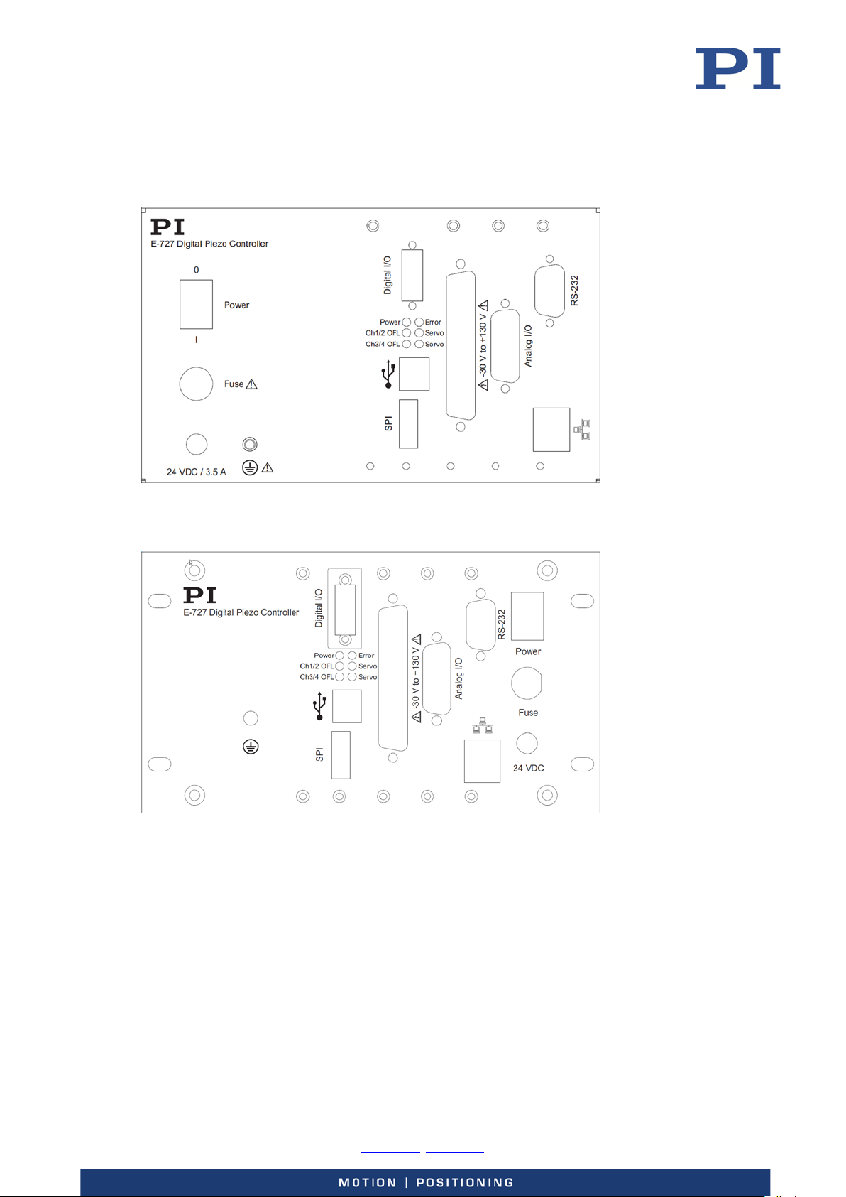
Figure 1: Front panel of E-727 digital piezo controllers, models E-727.xxx, .xxxA
Figure 2: Front panel of E-727 digital piezo controllers, models E-727.xxxP, E-727.xxxAP
Physik Instrumente (PI) GmbH & Co. KG, Auf der Roemerstrasse 1, 76228 Karlsruhe, Germany Page 14 / 228
Phone +49 721 4846-0, Fax +49 721 4846-1019, Email [email protected], www.pi.ws
Page 15
User Manual
Slotted fuse holder
For cartridge fuse 5 x 20 mm, changing the fuse see p. 205
24 VDC
M8 panel plug, 4-pin (p. 225)
Connection for the supply voltage.
M4 hole with fastening
Protective earth connection (p. 47)
Digital I/O
MDR14 (f)
Digital lines:
E727T0005, valid for E-727
BRO, 2018-03-23
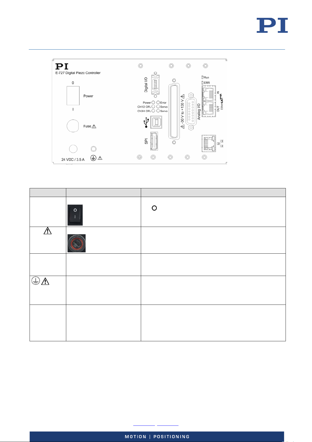
Figure 3: Front panel of E-727 digital piezo controllers, models E-727.xxxF, E-727.xxxAF
Labeling Type Function
Power Toggle switch
Power on/off switch:
position: E-727 is switched off
| position: E-727 is switched on
Fuse
To be used with the K050B0003 adapter (included in the
scope of delivery, p. 19)
material for protective earth
conductor
(p. 220)
A protective earth conductor must be connected to the E727 via the M4 hole and the fastening material, since the E727 is not grounded via the power supply connector.
Outputs: Triggering of external devices, output of the
servo cycles
Inputs: Triggering of data recorder or wave generator,
use in macros, reboot of E-727 (p. 220)
Physik Instrumente (PI) GmbH & Co. KG, Auf der Roemerstrasse 1, 76228 Karlsruhe, Germany Page 15 / 228
Phone +49 721 4846-0, Fax +49 721 4846-1019, Email [email protected], www.pi.ws
Page 16
User Manual
Power
Error
E727T0005, valid for E-727
BRO, 2018-03-23
Labeling Type Function
Ch1/2 OFL
Ch3/4 OFL
LED
green
LED
red
LED
yellow
Power-on and ready indicator:
Continuously lit: E-727 is ready for normal operation
Continuously off: E-727 is not connected to the supply
voltage
Alternately lit/off/lit: E-727 performs power-on or
reboot sequence
Error indicator:
Continuously lit: Error (error code ≠ 0)
Continuously off: No error (error code = 0)
Alternately lit/off: E-727 performs power-on or reboot
sequence
The error code can be queried with the ERR? command. The
query resets the error code to zero and the LED is switched
off.
Overflow indicator for the axes:
Continuously lit: At least one of the axes is in overflow
state
Continuously off: No axis is in overflow state
Both OFL LEDs are flashing together with the Servo
LEDs: E-727 searches for a DHCP server during poweron or reboot sequence
At least one OFL LED is permanently flashing while all
other LEDs are off: Firmware update failed (details see
“Updating Firmware”, p. 198)
The overflow state of the individual axes can be queried
with the OVF? command.
The overflow state can only occur in closed-loop operation.
In the overflow state, the axis does not reach the target
position because the amplifier(s) has/have reached the
range limit. In this case, readjustment of the sensor zeropoint is necessary, using the AutoZero functionality
provided by the E-727 firmware (details see p. 61).
For an axis in overflow state, the corresponding bit in the
response to the #5 command (Request Motion Status) is not
set (motion state = “not moving”).
Physik Instrumente (PI) GmbH & Co. KG, Auf der Roemerstrasse 1, 76228 Karlsruhe, Germany Page 16 / 228
Phone +49 721 4846-0, Fax +49 721 4846-1019, Email [email protected], www.pi.ws
Page 17
User Manual
Ch1/2 Servo
SPI
Display port
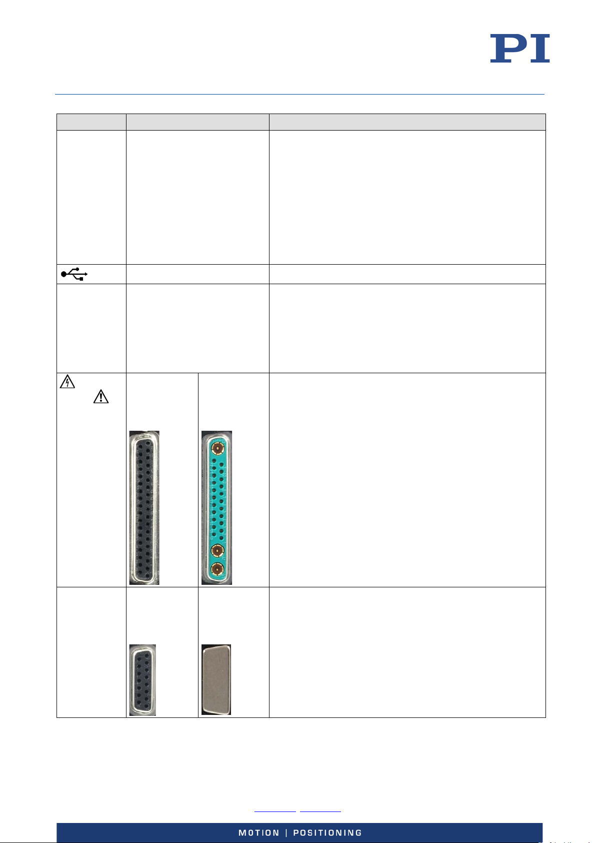
Connection to SPI (serial peripheral interface) master. Can
E-727.xRxxx*,
E-727.xCxxx*:
Socket for piezo stages; carries the voltage for the piezo
30 to 130 V) and the signals of the sensors in the
E727T0005, valid for E-727
BRO, 2018-03-23
Labeling Type Function
Ch3/4 Servo
LED
green
USB-B socket Universal serial bus for connection to the PC
Servo mode indicator for the axes:
Continuously lit: Servo mode is on (closed-loop
operation) for at least one of the axes
Continuously off: Servo mode is off (open-loop
operation) for the axes
Flashing: E-727 initializes parameters and – if the OFL
LEDs are flashing in addition - searches for a DHCP
server during power-on or reboot sequence
The servo mode of the individual axes can be queried with
the SVO? command.
be used for transferring position data from and to the E-727
with minimum latency and update rates as high as the servo
update rate of the E-727. It is also possible to send and
receive ASCII data so that the connected master has full
access to the PI General Command Set (GCS). See “SPIInterface” (p.
138) for details.
-30 V to
+130 V
Analog I/O E-727.xxxA*,
.xSxxx*:
D-Sub 37 (f)
(p. 219)
E-727.xxxAx*:
D-Sub 15 (f)
(p. 221)
D-Sub special
25W3 (f)
(p. 218)
E-727.xxx*,
E-727.xxxF*:
-
actuators (mechanics.
Only E-727.xxxA and .xxxAx - analog lines:
Inputs: Used for external sensors or as analog control
inputs
Outputs: Three sensor monitor lines, and one line that
can be used to monitor the position of an axis or for
controlling an external amplifier
Physik Instrumente (PI) GmbH & Co. KG, Auf der Roemerstrasse 1, 76228 Karlsruhe, Germany Page 17 / 228
Phone +49 721 4846-0, Fax +49 721 4846-1019, Email [email protected], www.pi.ws
Page 18
User Manual
RS-232
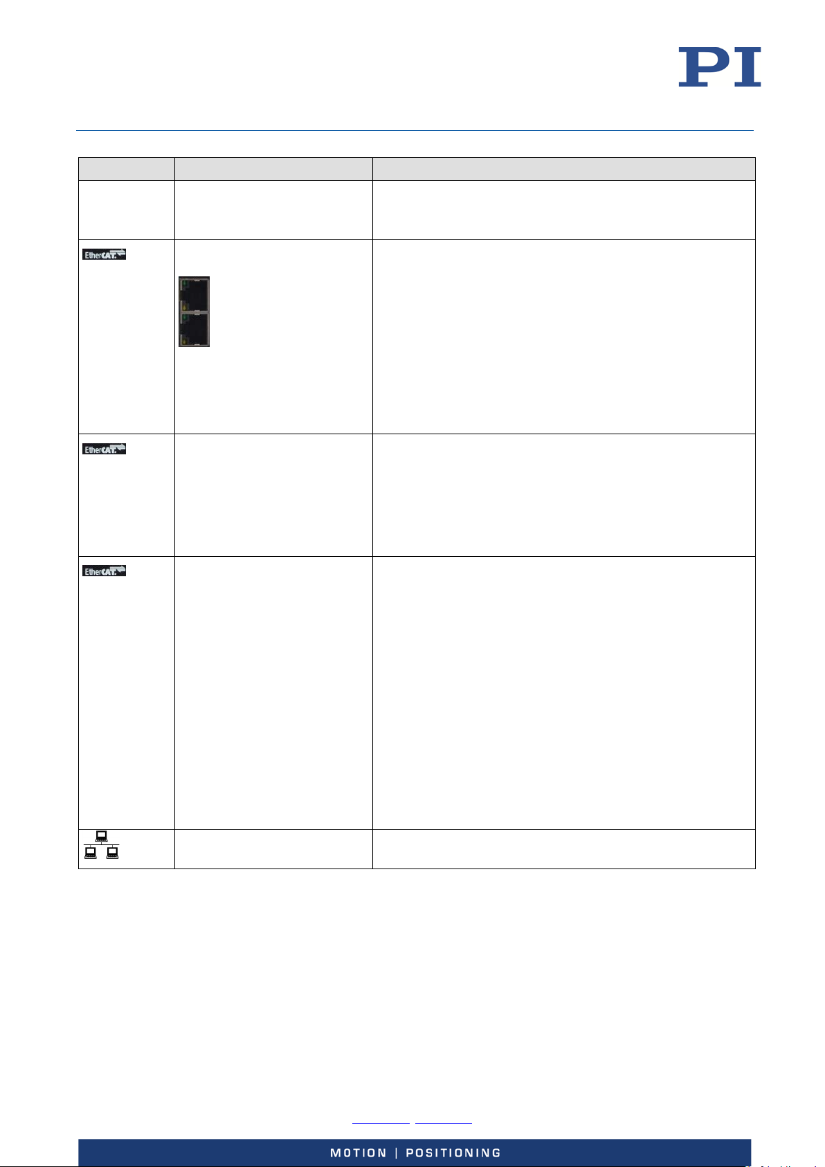
RJ45 socket with green and
E-727.xxxF* and .xxxAF* only:
E727T0005, valid for E-727
BRO, 2018-03-23
Labeling Type Function
D-Sub 9 (m)
(p. 223)
Serial connection to PC via UART, voltage level RS-232
If the E-727 is equipped with an EtherCAT interface, the RS-
232 connection is not present.
IN
OUT
RUN
ERR
yellow LED
IN (on top): Connection for EtherCAT master
OUT (below): Connection for the next EtherCAT slave
Green LED:
On: The E-727 is linked via EtherCAT, but does not
send/receive frames.
Flickering (load-dependent): The E-727 is linked via
EtherCAT and sends/receives frames.
Off: The E-727 is not linked via EtherCAT.
Yellow LED: Not used.
LED
green
E-727.xxxF* and .xxxAF* only:
EtherCAT communication state of the E-727:
Off: E-727 is in INIT state.
Blinking (2.5 Hz): E-727 is in PRE-OPERATIONAL state
Single flash: E-727 is in SAFE-OPERATIONAL state
On: E-727 is in OPERATIONAL state
LED
red
E-727.xxxF* and .xxxAF* only:
EtherCAT communication state of the E-727:
Off: No error, EtherCAT communication is running
Blinking (2.5 Hz): Invalid configuration. General
configuration error. Possible reason: State change
commanded by master is impossible due to register or
object settings.
Single flash: Local error. E-727 has changed the
EtherCAT state autonomously. Possible reason 1: A host
watchdog timeout has occurred. Possible reason 2:
Synchronization error, E-727 changes to SAFEOPERATIONAL automatically.
Double flash: An application watchdog timeout has
occurred. Possible reason: Sync Manager Watchdog
timeout.
RJ45 socket Ethernet interface for communication via TCP/IP, see p. 55
for details
* x is a placeholder; for the individual models see “Model Overview” (p. 13).
Physik Instrumente (PI) GmbH & Co. KG, Auf der Roemerstrasse 1, 76228 Karlsruhe, Germany Page 18 / 228
Phone +49 721 4846-0, Fax +49 721 4846-1019, Email [email protected], www.pi.ws
Page 19
User Manual
E-727
Digital piezo controller according to the order
K050B0003
Adapter for the power supply connection; barrel connector to M8 4-pin connector
E727T0005
User Manual for the E-727, this document
E-727.IO3x
Analog input cable, D-Sub 15 (m) to open end, 1 m. For further details, see p. 223.
Order number
Description
E-710.SCN
Dynamic Digital Linearization (DDL) option. The DDL makes it possible to achieve
E727T0005, valid for E-727
BRO, 2018-03-23
Scope of Delivery
Item number Description
000023194 Separate 24 V wide-range-input power supply (120 W/5 A) for use with line
voltages from 100 to 240 VAC and voltage frequencies of 50 or 60 Hz, with barrel
connector
3763 Power cord
C-815.34 RS-232 null-modem cable, 3 m, 9/9-pin
Not for E-727.xxxF and .xxxAF models.
C-815.563 Cross-over network cable for direct connection with the PC via TCP/IP
000011448 USB cable (type A to type B) for connection to the PC
E-727.CD Product CD with software and user manuals for the E-727
Models with additional analog interfaces only (E-727.xxxA, E-727.xxxAx):
Accessories
P-895.4LDS Adapter cable for four channels, Sub-D 37 (m) to 8 x Lemo (4 x piezo, 4 x sensor);
0.3 m. For piezo stages with piezoresistive or strain gauge sensors.
PI has to adapt the cable to the piezo stage with which the cable is to be used.
Therefore the cable and the piezo stage have to be ordered together.
E-727.IO8 Adapter cable for the Analog I/O socket of E-727.xxxA and .xxxAx models, D-Sub
15 (m) to 8 x BNC, 0.4 m. For further details, see p. 224.
significantly better position accuracy for dynamic applications with periodic
motion. It is used in conjunction with the wave generator output and in addition
to the "normal" servo algorithm in closed-loop operation. You can activate the
DDL after purchase and without opening the device. See "Dynamic Digital
Linearization (DDL)" (p.
E-712.U1 Advanced Piezo Control option. Advanced Piezo Control (APC) is an alternative
control algorithm for closed-loop operation of piezo actuator systems. You can
activate the license after purchase and without opening the device. See the
separate E712T0007 Technical Note for more information.
108) for more information.
To order, contact our customer service department (p. 227).
Physik Instrumente (PI) GmbH & Co. KG, Auf der Roemerstrasse 1, 76228 Karlsruhe, Germany Page 19 / 228
Phone +49 721 4846-0, Fax +49 721 4846-1019, Email [email protected], www.pi.ws
Page 20
User Manual
E727T0005, valid for E-727
BRO, 2018-03-23
Functional Principles
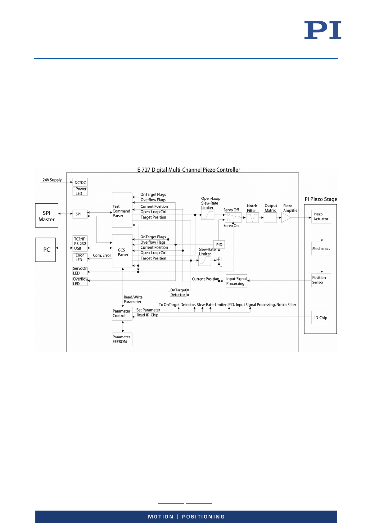
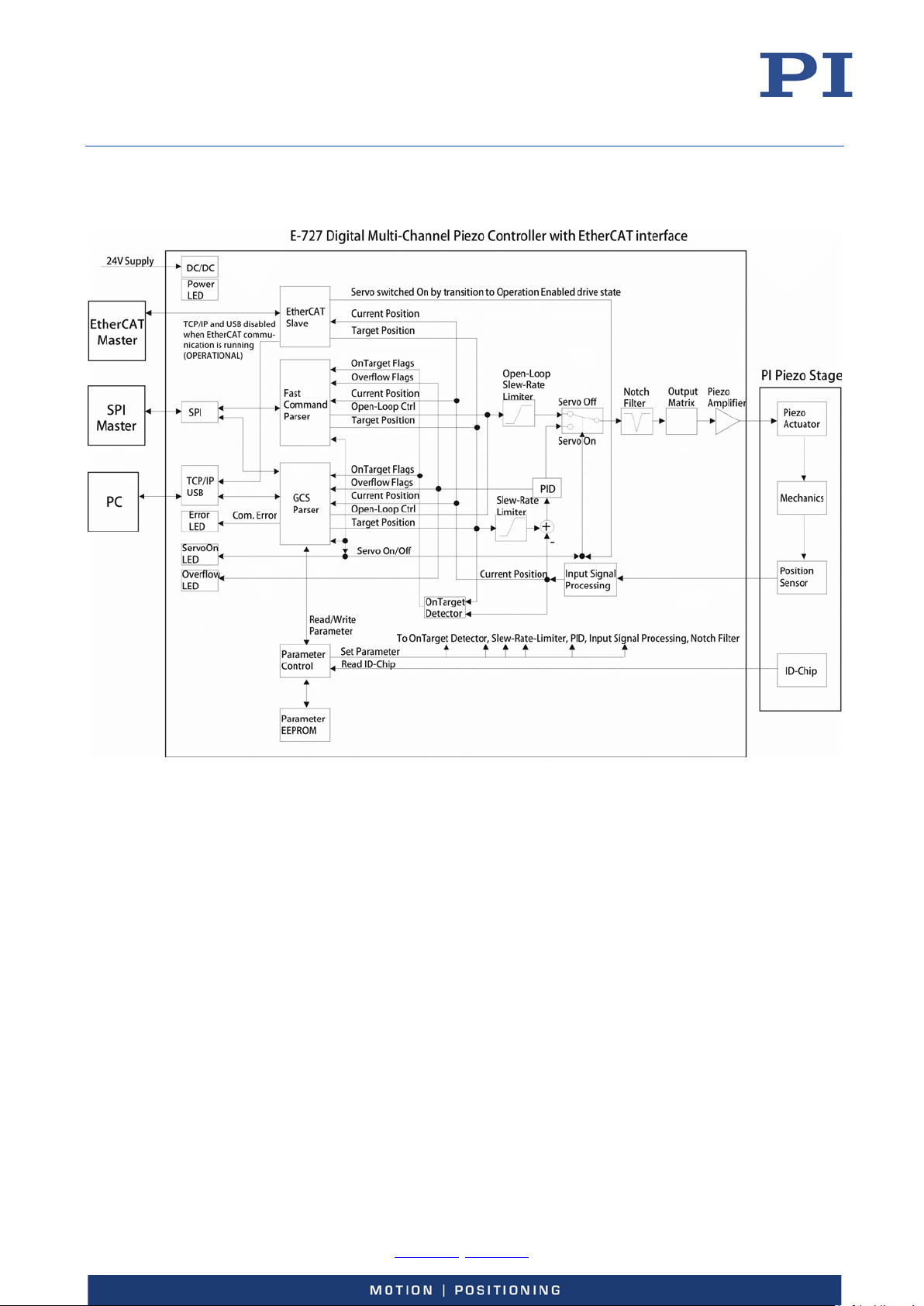
Block Diagrams
The following block diagrams show the basic structure of the E-727.
For clear readability, the block diagrams do not contain the additional analog inputs and outputs
which are present with E-727.xxxA and E-727.xxxAx models.
Block diagram for models without EtherCAT interface:
Figure 4: Block diagram of E-727 models without EtherCAT interface
Physik Instrumente (PI) GmbH & Co. KG, Auf der Roemerstrasse 1, 76228 Karlsruhe, Germany Page 20 / 228
Phone +49 721 4846-0, Fax +49 721 4846-1019, Email [email protected], www.pi.ws
Page 21
User Manual
E727T0005, valid for E-727
BRO, 2018-03-23
Block diagram for models with EtherCAT interface:
Figure 5: Block diagram of E-727 models with EtherCAT interface
Physik Instrumente (PI) GmbH & Co. KG, Auf der Roemerstrasse 1, 76228 Karlsruhe, Germany Page 21 / 228
Phone +49 721 4846-0, Fax +49 721 4846-1019, Email [email protected], www.pi.ws
Page 22
User Manual
E727T0005, valid for E-727
BRO, 2018-03-23
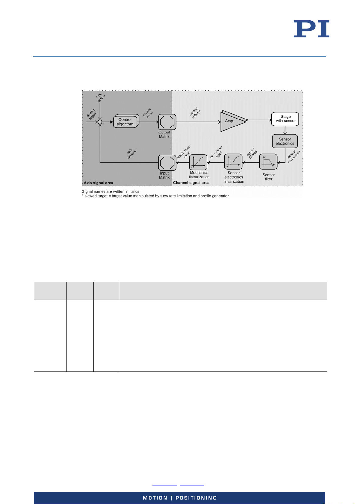
The E-727 controls the motion of the logical axes of the connected stage(s) in open-loop or closedloop operation. The block diagram below shows the signal path for an axis in closed-loop
operation.
Figure 6: Block diagram of an axis in closed-loop operation
Axes, Channels, Functional Elements
The following table contains the items that can be accessed with commands of the PI General
Command Set (GCS).
When controlled by an EtherCAT master (E-727.xxxF and .xxxAF only), the EtherCAT master
specifies target positions for the logical axes of the E-727. For further information, see "EtherCAT
Interface" (S. 158).
Item Num-
ber
Logical
axis
3 or 4 1 to 3
Identifier
or
1 to 4
Description
The supported number of logical axes depends on the E-727 model.
The logical axes represent the motion of the stage in the firmware of the E-
727. A logical axis corresponds to an axis of a linear coordinate system.
All commands for the motion of a stage refer to logical axes.
The value of the Number Of System Axes parameter (ID 0x0E000B02)
specifies the number of axes.
The input and output signal channels of the E-727 are allocated to the
logical axes via matrices (input matrix: parameters 0x07000500 to
0x07000506; output matrix: parameters 0x09000000 to 0x09000003).
Physik Instrumente (PI) GmbH & Co. KG, Auf der Roemerstrasse 1, 76228 Karlsruhe, Germany Page 22 / 228
Phone +49 721 4846-0, Fax +49 721 4846-1019, Email [email protected], www.pi.ws
Page 23
User Manual
depends
hannel 4
sensor or as a control source, see “Using the Analog Input” (p. 79) for
E727T0005, valid for E-727
BRO, 2018-03-23
Item Num-
ber
Input
signal
channels
Number
on the
E-727
model
Identifier
1 to
max.
number
of
channels
Description
E-727.3CD, .3CDF, .3CDP:
3 channels, intended for the capacitive sensors in the stage(s), input on the
socket for piezo stages (p. 218).
E-727.3CDA, .3CDAF, .3CDAP:
7 channels. Channels 1 to 3 are intended for the capacitive sensors in the
stages(s), input on the socket for piezo stages (p. 218). Channels 4 to 7 are
the analog inputs available on the Analog I/O socket (p. 221). The input
range of the analog inputs can be configured via the value of the Sensor
Range Factor parameter (ID 0x02000100) as follows:
1: ±5 V
2: ±10 V
E-727.3SD, .3SDF, .3SDP. .4SD, .3RD, .3RDF, .3RDP, .4RD:
4 channels. Input on the socket for piezo stages (p. 219
intended for the piezoresistive or strain gauge sensors in the stage(s). Via
the value of the Sensor Range Factor parameter (ID 0x02000100), c
can be configured as follows:
). Channels 1 to 3 are
1: Use with a piezoresistive or strain gauge sensor (pins 6, 24, 25)
2: Use with a PT1000 temperature sensor (pins 1, 20)
E-727.3SDA, .3SDAF, .3SDAP, .3RDA, .3RDAF, .3RDAP:
7 channels. Channels 1 to 3 are intended for the piezoresistive or strain
gauge sensors in the stages(s), input on the socket for piezo stages (p. 219).
Via the value of the Sensor Range Factor parameter (ID 0x02000100),
channel 4 can be configured as follows:
1: Use with a piezoresistive or strain gauge sensor (input via pins 6, 24,
25 of the socket for the piezo stage(s) (p. 219))
2: Use with a PT1000 temperature sensor (input via pins 1, 20 of the
socket for the piezo stage(s))
3: Use as analog input 1 with a range of ±5 V (input via pins 2 and 9 on
the Analog I/O socket (p. 221))
4: Use as analog input 1 with a range of ±10 V (input via pins 2 and 9 on
the Analog I/O socket)
Channels 5 to 7 are the analog inputs 2 to 4 available on the Analog I/O
socket. Their input ranges can be configured via the value of the Sensor
Range Factor parameter (ID 0x02000100) as follows:
1: ±5 V
2: ±10 V
General Notes:
The analog inputs on the Analog I/O socket can be used for an external
Physik Instrumente (PI) GmbH & Co. KG, Auf der Roemerstrasse 1, 76228 Karlsruhe, Germany Page 23 / 228
Phone +49 721 4846-0, Fax +49 721 4846-1019, Email [email protected], www.pi.ws
Page 24
User Manual
details.
Number Of
E727T0005, valid for E-727
BRO, 2018-03-23
Item Num-
ber
Output
signal
channels
Digital
inputs
4 1 to 4 E-727.xxx, .xxxF, .xxxP:
4 1 to 4 1 to 4 identify digital input lines 1 to 4 of the Digital I/O socket (p. 220).
Identifier
Description
The number of sensor channels available on the socket for the piezo stage
can be queried via the Number Of Sensor Channels parameter (ID
0x0E000B03). Note that this number will change with E-727.3RDA, .3RDAF,
.3RDAP, .3SDA, .3SDAF and .3SDAP models depending on the usage of
channel 4.
The total number of input signal channels can be queried via the
Input Channels parameter (ID 0x0E000B00).
The channels are intended for the piezo actuators in the stage(s), output on
the socket for piezo stages (p. 218 or p. 219).
E-727.xxxA, .xxxAx:
Channels 1 to 3 are intended for the piezo actuators in the stage(s), output
on the socket for piezo stages (p. 218 or p. 219).
Via the value of the Select Output Type parameter (ID 0x0A000003),
channel 4 can be configured as follows:
1: Output voltage for a piezo actuator in the stage, output as Piezo Ch 4
on the socket for piezo stages (p. 218 or p. 219).
2: Position monitor of an axis, output on pin 8 of the Analog I/O socket
(p. 221).
5: Control signal for an external amplifier, output on pin 8 of the Analog
I/O socket.
Further details see “Using the Analog Output” (p. 88).
General Notes:
The number of channels available on the socket for the piezo stage can be
queried via the Number Of Piezo Channels parameter (ID 0x0E000B04).
Note that this number will change with E-727.xxxA and .xxxAx models
depending on the usage of channel 4.
The total number of output signal channels can be queried via the Number
Of Output Channels parameter (ID 0x0E000B01).
Note that the sensor monitor lines 1 to 3 on the Analog I/O socket are not
available as output signal channels in the firmware of the E-727 and not
accessible for commands.
Digital inputs 1 to 3 can be used to trigger the data recorder (DRT
command) or wave generator output (WGO command). Furthermore, they
can be used in macros (MAC command).
Via the Reboot On DIO Input parameter (ID 0x0E001500), the digital input 4
(pin 2 of Digital I/O) can be configured for one of the following options:
Same functions as with digital inputs 1 to 3 (default setting)
Reset functionality: The input triggers a system reboot (active LOW).
Controller behaves just like after power-on.
Physik Instrumente (PI) GmbH & Co. KG, Auf der Roemerstrasse 1, 76228 Karlsruhe, Germany Page 24 / 228
Phone +49 721 4846-0, Fax +49 721 4846-1019, Email [email protected], www.pi.ws
Page 25
User Manual
DDL tables
3
1 to 3
The DDL tables contain the data of the Dynamic Digital Linearization (DDL)
Data
≤8
1, 2, …
The data recorder tables contain the recorded data (a total of 262144
Overall
1 1 E-727 as an overall system.
E727T0005, valid for E-727
BRO, 2018-03-23
Item Num-
ber
Digital
3 1 to 3 1 to 3 identify digital output lines 1 to 3 of the Digital I/O socket (p. 220).
outputs
Wave
3 1 to 3 The number of wave generators corresponds to the number of logical axes.
generators
Wave
40 1 to 40 The wave tables contain the (temporarily) saved data (a total of 262144
tables
Identifier
Description
These lines can be used to trigger external devices in conjunction with axis
motion (CTO command and corresponding parameters (IDs 0x18000201 to
0x18000209)).
Digital output 4 (pin 8 of the Digital I/O socket) is not accessible for
commands. It outputs the servo cycles.
The number of digital output lines that are accessible by commands can be
queried via the Number Of Trigger Outputs parameter (ID 0x0E000B05).
Each wave generator is permanently allocated to a logical axis.
th
If the E-727 is configured for a 4
axis, a 4th wave generator is also present.
points) for the waveforms that are output by the wave generators.
The value of the Number Of Waves parameter (ID 0x1300010A) indicates
the number of wave tables.
feature. The number of DDL tables corresponds to the number of logical
axes. Each DDL table is permanently allocated to a logical axis.
If the E-727 is configured for a 4th axis, a 4th DDL table is also present.
The total number of points provided for the DDL tables is 262144, indicated
by the Max DDL Points parameter, ID 0x1400000B.
recorder
tables
system
Firmware
units
points). The number of data recorder tables can be set with the Data
Recorder Chan Number parameter (ID 0x16000300). The Max Number Of
Data Recorder Channels parameter (ID 0x16000100) indicates the
maximum number of data recorder tables.
2 1, 2 The number of different firmware units present in the E-727.
Physik Instrumente (PI) GmbH & Co. KG, Auf der Roemerstrasse 1, 76228 Karlsruhe, Germany Page 25 / 228
Phone +49 721 4846-0, Fax +49 721 4846-1019, Email [email protected], www.pi.ws
Page 26
User Manual
Parameters and
Parameters reflect the properties of the E-727 and the connected stage and define the
Control algorithm
For better position accuracy and performance, the E-727 can be operated in closed-
Wave generator
Each axis can be controlled by a wave generator that outputs waveforms. The wave
E727T0005, valid for E-727
BRO, 2018-03-23
Important Components of the Firmware
The firmware of the E-727 provides the following functional units:
Firmware
Component
Commands Communication with the E-727 can be managed using the commands of the PI General
command levels
Description
Command Set (GCS; version 2.0). The GCS is independent of the hardware (controller,
stages connected).
See the GCS commands manual PZ281E for more information. You can find a list of
available GCS commands in the "Command Overview" section (p. 175).
The E-727 can also be controlled by an SPI master, see “SPI Interface” (p. 138).
E-727 models with EtherCAT interface can also be controlled by an EtherCAT master,
see “EtherCAT Interface” (p. 158).
behavior of the system (e.g. settings for the control algorithm and notch filters (p. 35)).
The parameters can be divided into the following categories:
Protected parameters whose default settings cannot be changed
Parameters that can be set by the user to adapt to the application
The write permission for the parameters is determined by command levels. The
current command level can be changed with the CCL command. This may require
entering a password.
For more information, see "Parameters" (p. 179).
The values of some parameters are stored on the ID chip (p. 39) of the stage. They are
loaded to the volatile and nonvolatile memory when the E-727 is switched on or
rebooted.
for closed-loop
operation
Data recorder The E-727 contains a real-time data recorder (p. 64). This can record different input
Macros The E-727 can save macros—command sequences can be defined and permanently
loop mode. A control algorithm (with sensor feedback) will then apply corrections to
the control value. For more information, see “Control Details” (p.
generator is especially suited for dynamic applications in which periodic motions of the
axis are executed (p.
and output signals (e. g. current position, sensor input, output current) from different
data sources (e. g.logical axes, input and output signal channels).
stored in the nonvolatile memory of the device via the macro function. A start-up
macro can be defined that is executed each time when the E-727 is switched on or
rebooted. This simplifies stand-alone operation (operation without a connection to the
PC). Further information can be found in the "Controller Macros" section (p. 115).
93).
35).
Physik Instrumente (PI) GmbH & Co. KG, Auf der Roemerstrasse 1, 76228 Karlsruhe, Germany Page 26 / 228
Phone +49 721 4846-0, Fax +49 721 4846-1019, Email [email protected], www.pi.ws
Page 27
User Manual
E727T0005, valid for E-727
BRO, 2018-03-23
Input Signal Processing
The following processing is applied to all input signal channels of the E-727 (channels for internal
sensors of the mechanics and for analog input lines):
Analog to digital conversion
Digital processing (filtering and linearization / scaling)
Allocation of input signal channels to axes via the input matrix to calculate the axis
positions from the input signals
Figure 7: Input signal processing for E-727.3CDA
Analog to digital conversion
The results of the analog to digital conversion can be queried with the TAD? command for all
channels.
Digital processing
The digital processing of the input signals comprises the following steps:
Digital filtering
Electronics linearization
Mechanics linearization
Figure 8: Digital processing of the input signals, shown for E-727.3CDA
Physik Instrumente (PI) GmbH & Co. KG, Auf der Roemerstrasse 1, 76228 Karlsruhe, Germany Page 27 / 228
Phone +49 721 4846-0, Fax +49 721 4846-1019, Email [email protected], www.pi.ws
Page 28
User Manual
E727T0005, valid for E-727
BRO, 2018-03-23
The following parameters determine the digital filter settings:
Digital Filter Type
parameter ID 0x05000000
0 = no filter
1 = IIR low-pass filter, 2nd order
99 = USER filter (coefficients of the filter are given by User Filter Param. 1 to 5 (IDs
0x05000101 to 0x05000105)
Digital Filter Bandwidth
parameter ID 0x05000001
Gives the cut-off-frequency f
Type" is set to "IIR low-pass filter, 2nd order".
Note that the duration of the signal processing for a sensor results from two
portions:
1) Duration of the analog sensor processing, which takes about 100 µs
2) Duration of the digital filtering which depends on the f
frequencies
f < f
of the IIR low-pass filter. Only used if "Digital Filter
g
setting: for signal
g
/2, the duration of the filtering can be estimated as follows: t ≈ 0.216 / f
g
g
In PIMikroMove, the digital filter parameters are available in the Sensor Mechanics parameter
groups in the Device Parameter Configuration window.
Polynomial linearization is used to correct system performance. The basic form of the polynomials
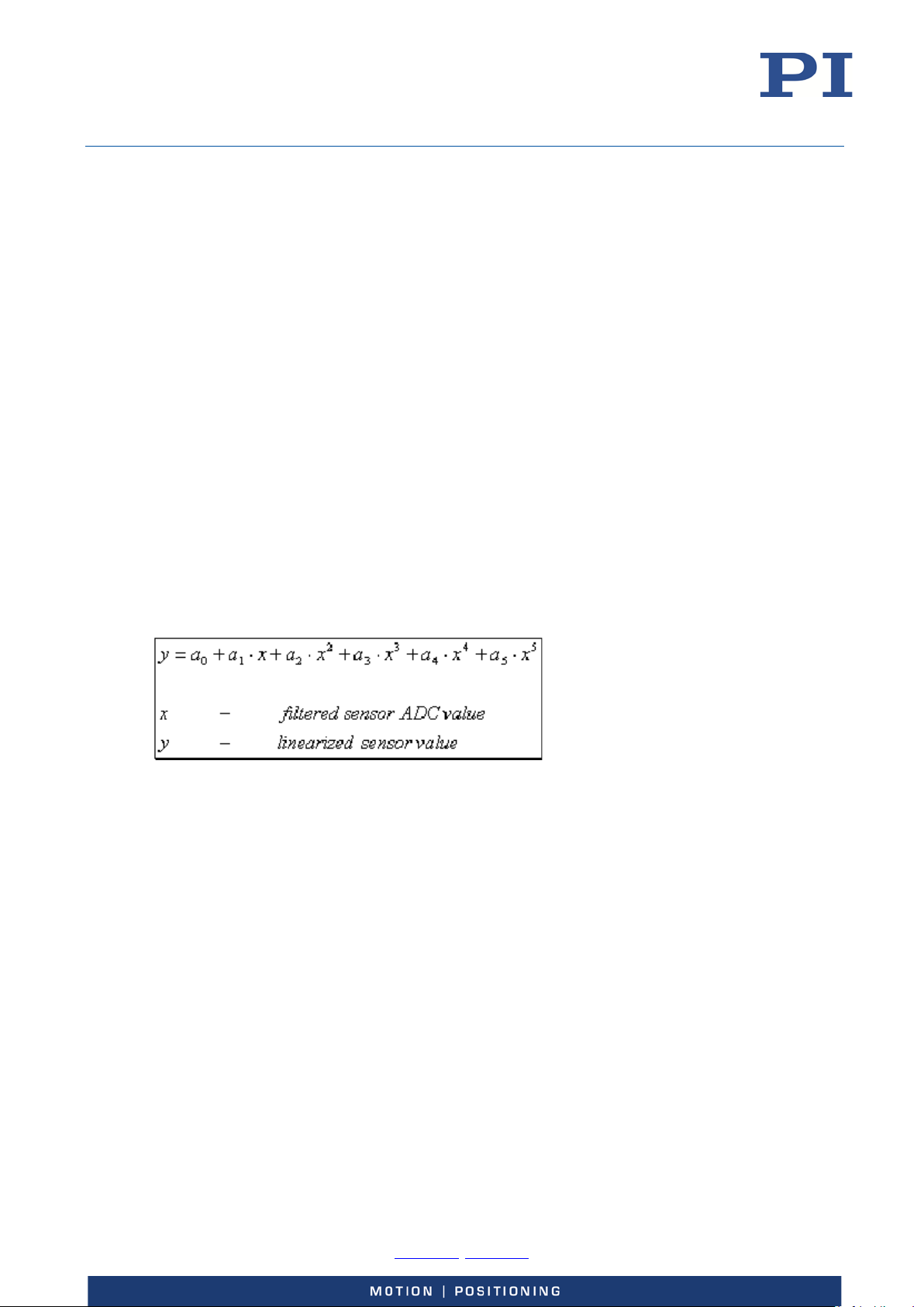
is as follows:
To make the system components easily replaceable, sensor (i.e. mechanics) and electronics use
separate polynomials. The coefficients of the polynomials are determined at the factory. Some
terms of the polynomials are provided for future application and presently set to zero. The
following terms are currently in use:
nd
Electronics linearization: offset, gain, 2
, 3rd and 4th order correction. The
corresponding coefficients of the polynomial are given by the parameters
0x03000100 to 0x03000500. They are independent of the connected mechanics and
may not be changed by the user. In PIMikroMove, these parameters are available in
the Sensor Electronics parameter groups in the Device Parameter Configuration
window.
Mechanics linearization: offset, gain, 2
nd
, 3rd and 4th order correction. The
corresponding coefficients of the polynomial are given by the parameters
0x02000200 to 0x02000600. They depend on the connected mechanics. In
PIMikroMove, these parameters are available in the Sensor Mechanics parameter
groups in the Device Parameter Configuration window.
For the internal sensors in the mechanics, the parameters should not be changed by
the user. For analog input lines (E-727.xxxA, .xxxAx only; see p. 22 for details),
changing the offset and gain values is required to scale the analog input to suitable
Physik Instrumente (PI) GmbH & Co. KG, Auf der Roemerstrasse 1, 76228 Karlsruhe, Germany Page 28 / 228
Phone +49 721 4846-0, Fax +49 721 4846-1019, Email [email protected], www.pi.ws
Page 29

User Manual
∗
=
7
6
5
4
3
2
1
37363534333231
27262524232221
17161514131211
3
2
1
InputCh
InputCh
InputCh
InputCh
InputCh
InputCh
InputCh
aaaaaaa
aaaaaaa
aaaaaaa
Axis
Axis
Axis
E727T0005, valid for E-727
BRO, 2018-03-23
position values (see "Using the Analog Input" (p. 79) for more information and
examples).
If the connected mechanics has an ID-chip, the coefficients will be read in from the
ID-chip (see "ID-Chip Support / Stage Replacement" (p. 125) for more information).
The TNS? command reports the result after the linearization for the electronics (normalized value,
dimensionless), while the TSP? command reports the result after the linearization for the
mechanics (scaled value, the unit is µm).
Allocation of input signal channels to axes
Multiple sensors can be used to monitor the position of an axis, especially with rotation axes. The
internal sensors in the mechanics are active by default, while additional, external sensors can
optionally be connected to the analog input lines of E-727.xxxA or .xxxAx models. The axis
positions are calculated from the position values of the input signal channels using the input
matrix. The number of rows and columns of the input matrix depends on the E-727 model. The
example below shows the matrix for an E-727.3CDA model which controls 3 axes and has 3
channels for internal sensors and 4 additional analog input lines (the last four input signal
channels):
In equation form:
Axis
= a11InputCh1 + a12InputCh2 + a13InputCh3+ a14InputCh4+ a15InputCh5+ a16InputCh6+ a17InputCh7
1
Axis
= a21InputCh1 + a22InputCh2 + a23InputCh3+ a24InputCh4+ a25InputCh5+ a26InputCh6+ a27InputCh7
2
Axis
= a31InputCh1 + a32InputCh2 + a33InputCh3+ a34InputCh4+ a35InputCh5+ a36InputCh6+ a37InputCh7
3
The matrix coefficients are given by the Position From Sensor n parameters (n depends on the
number of input signal channels present in the E-727). With an E-727.3CDA, for example, the
following parameters are used (with i = 1 to 3 for the three axes of the system, i.e. each parameter
has a different value for each of the logical axes):
= Position From Sensor 1, parameter ID 0x07000500
a
i1
= Position From Sensor 2, parameter ID 0x07000501
a
i2
= Position From Sensor 3, parameter ID 0x07000502
a
i3
These coefficients are for the internal sensors in the mechanics (socket for piezo
stages).
= Position From Sensor 4, parameter ID 0x07000503
a
i4
= Position From Sensor 5, parameter ID 0x07000504
a
i5
= Position From Sensor 6, parameter ID 0x07000505
a
i6
= Position From Sensor 7, parameter ID 0x07000506
a
i7
These coefficients are for the analog input lines (Analog I/O socket).
Physik Instrumente (PI) GmbH & Co. KG, Auf der Roemerstrasse 1, 76228 Karlsruhe, Germany Page 29 / 228
Phone +49 721 4846-0, Fax +49 721 4846-1019, Email [email protected], www.pi.ws
Page 30
User Manual
E727T0005, valid for E-727
BRO, 2018-03-23
In PIMikroMove, these parameters are available in the Axis Definition parameter groups in the
Device Parameter Configuration window. In addition, you can check the matrix coefficients in the
Axis Matrices window (open via View -> Axis Matrices menu item of the Device Parameter
Configuration window).
INFORMATION
The coefficients of the input matrix are determined during calibration at the factory. The preset
values of the coefficients for the internal sensors should not be changed.
If the connected mechanics has an ID-chip, the coefficients will be read in from the ID-chip (see
"ID-Chip Support / Stage Replacement" (p. 125) for more information).
E-727.xxxA and .xxxAx models only:
The coefficients for the analog input lines should be set to zero as long as no external sensors are
connected to the analog input lines or when the analog input is used for control value generation
(see "Using the Analog Input" (p. 79) for more information).
While TSP? reports the position values of the input signal channels, the POS? command reports the
axis positions calculated via the input matrix (the unit is µm or µrad).
Control Value Generation
The control value for the motion of an axis can result from multiple sources (see below).
Furthermore, the feedback from multiple sensors can be used to maintain the axis position,
depending on the current operating mode. The interpretation of the control values depends on the
settings of the output matrix (see "Output Generation" (p. 34) for more information). By default,
the output matrix is set up so that control values correspond numerically to axis position values.
The E-727 provides the following operating modes:
Open-loop control (also referred to as "servo-off state" in this document): No
control algorithm is used, and the sensor feedback does not participate in the
control value generation.
Closed-loop control (also referred to as "servo-on state" in this document): Sensor
feedback participates in the control value generation.
For each logical axis, a control algorithm is used to generate corrections to the
control value (default: PID algorithm). In addition, two notch filters are used for each
axis (default: only active in closed-loop operation). The settings for control algorithm
and notch filters are accessible as parameters. See "Control Details" (p. 35), "Servo
Controller Dynamic Tuning" (p. 128) and " Parameters" (p. 179) for more
information.
The operating mode can be selected with the SVO command for each axis. By default, open-loop
control is active after power-on. Using the Power Up Servo On Enable parameter (ID 0x07000800),
you can set up the individual axes to start with closed-loop control. When switching from openloop to closed-loop control, the behaviour depends on the setting made with parameter
0x0e002000. Default: The current axis position is set as the target position. For further details, see
Physik Instrumente (PI) GmbH & Co. KG, Auf der Roemerstrasse 1, 76228 Karlsruhe, Germany Page 30 / 228
Phone +49 721 4846-0, Fax +49 721 4846-1019, Email [email protected], www.pi.ws
Page 31

User Manual
E727T0005, valid for E-727
BRO, 2018-03-23
“Parameter Overview” (p. 183). Switching from closed-loop to open-loop control sets the current
closed-loop control value as the open-loop control value.
E-727 models with EtherCAT interface: A transition to the Operation Enabled state of the drive
state machine switches the axis to closed-loop control. The axis remains in closed-loop operation
until it is switched to open-loop control by an SVO command via TCP/IP or USB interface.
The E-727 supports the following control sources:
Move commands, sent from the command line or from a macro:
MOV and MVR in closed-loop operation
SVA and SVR in open-loop operation
IMP and STE commands generate an impulse or step response
Wave Generator: The wave generator is enabled with WGO.
An offset value can be added to the wave generator output using the WOS
command.
Analog Input (only possible with E-727.3CDA, .3RDA, .3SDA models): The analog
control input is enabled via parameter settings, see "How to work with the Analog
Input" (p. 79) for more information.
An offset value can be added to the analog input scaled value using the AOS
command.
AutoZero procedure: this procedure is started by the ATZ command and performed
in open-loop operation only (if servo is on, it will be switched off automatically
during the AutoZero procedure and on again afterwards). The AutoZero procedure
has the highest priority, i.e. it will overwrite the control values given by all other
sources. When the analog control input is enabled, it will be disabled automatically
at the start of the AutoZero procedure and reenabled again when AutoZero is
finished. See "AutoZero Procedure" (p. 61) for details.
The E-727 can also be commanded via an SPI master. Depending on the SPI data segment used,
target values (with same write priority as analog control input) or GCS commands can be sent from
the SPI master. See “SPI Interface” (p. 138) for details.
E-727 models with EtherCAT interface can also be commanded by an EtherCAT master. The
EtherCAT master sends target values for closed-loop operation. The PC interfaces are disabled
when EtherCAT communication is running (OPERATIONAL state). For further details on the
interaction of the EtherCAT interface with other control sources, see "EtherCAT Interface" (p. 158).
Physik Instrumente (PI) GmbH & Co. KG, Auf der Roemerstrasse 1, 76228 Karlsruhe, Germany Page 31 / 228
Phone +49 721 4846-0, Fax +49 721 4846-1019, Email [email protected], www.pi.ws
Page 32
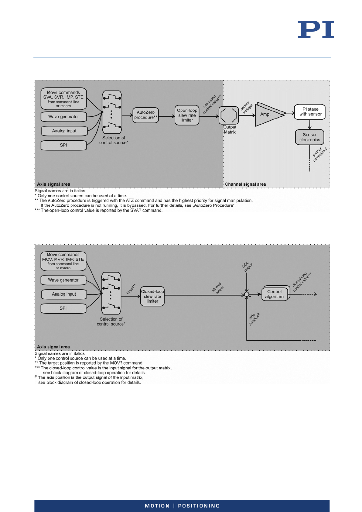
User Manual
E727T0005, valid for E-727
BRO, 2018-03-23
Open-Loop Control (all E-727 models):
Figure 9: Control sources for an axis in open-loop operation
Closed-Loop Control (E-727 models without EtherCAT interface):
Figure 10: Control sources for an axis in closed-loop operation
Physik Instrumente (PI) GmbH & Co. KG, Auf der Roemerstrasse 1, 76228 Karlsruhe, Germany Page 32 / 228
Phone +49 721 4846-0, Fax +49 721 4846-1019, Email [email protected], www.pi.ws
Page 33
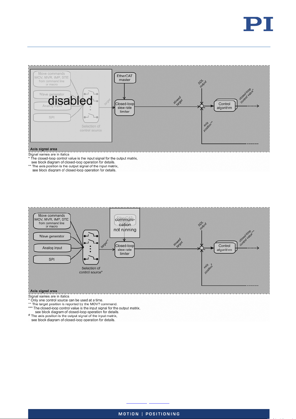
User Manual
E727T0005, valid for E-727
BRO, 2018-03-23
Closed-Loop Control when EtherCAT communication is running (E-727.xxxF, .xxxAF only):
Figure 11: EtherCAT master controls an axis in closed-loop operation
Closed-Loop Control when EtherCAT communication does not run (E-727.xxxF, .xxxAF only):
Figure 12: EtherCAT communication does not run; control sources for an axis in closed-loop operation
Physik Instrumente (PI) GmbH & Co. KG, Auf der Roemerstrasse 1, 76228 Karlsruhe, Germany Page 33 / 228
Phone +49 721 4846-0, Fax +49 721 4846-1019, Email [email protected], www.pi.ws
Page 34
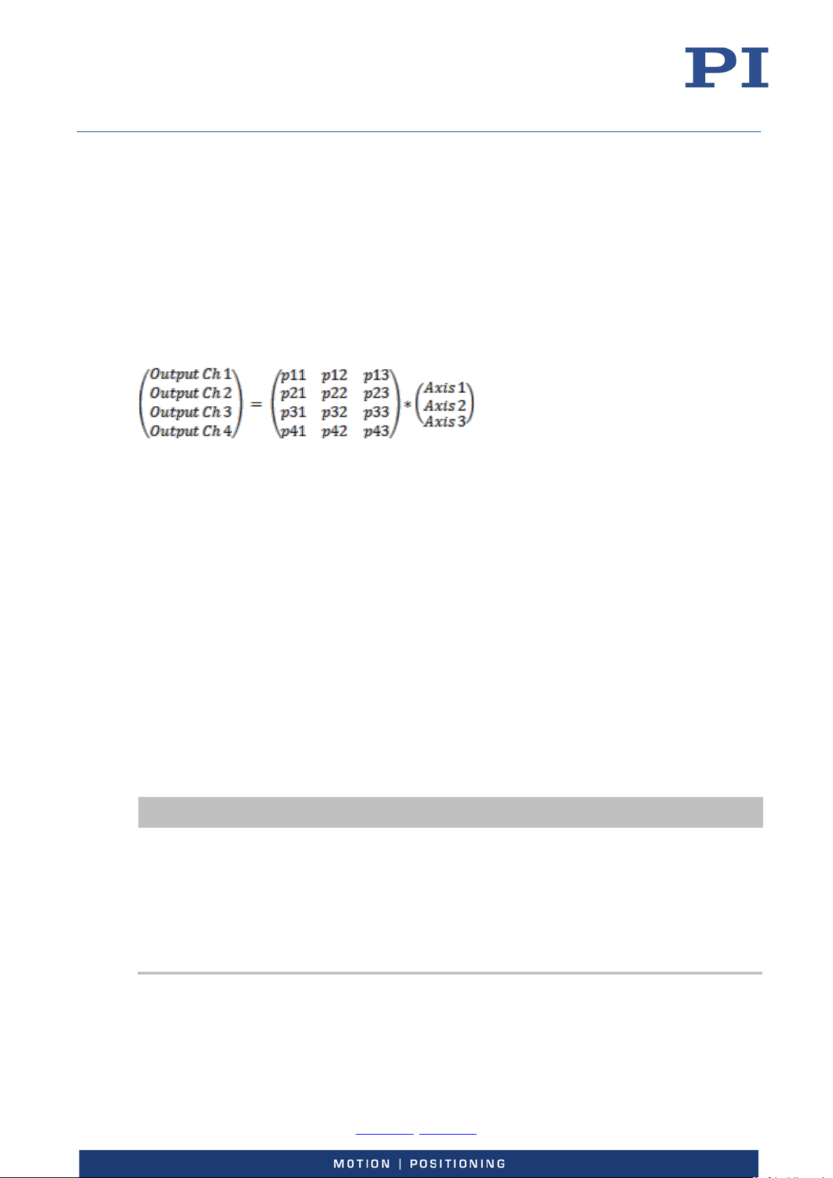
User Manual
E727T0005, valid for E-727
BRO, 2018-03-23
Output Generation
Multiple piezo actuators can be used to execute the motion of an axis, i.e. multiple output signal
channels (piezo amplifiers) can be involved. The control value for an axis is transformed to control
voltage values for the output channels via the output matrix. After the digital-to-analog
conversion, the resulting control voltage values are sent to the piezo amplifiers whose output
drives the actuators in the mechanics.
With E-727.xxxA and .xxxAx models, the control voltage values can also be output by the analog
output line to control an external amplifier (see "Using the Analog Output" (p. 88) for more
information).
Output matrix of the E-727:
In equation form:
OutputCh
OutputCh
OutputCh
OutputCh
= p11Axis1 + p12Axis2 + p13Axis3
1
= p21Axis1 + p22Axis2 + p23Axis3
2
= p31Axis1 + p32Axis2 + p33Axis3
3
= p41Axis1 + p42Axis2 + p43Axis3
4
The matrix coefficients are given by the following parameters (with i = 1 to 3, or 1 to 4, depending
on the number of axes provided by the E-727, i.e. each parameter has a different value for each of
the logical axes):
p
= Driving Factor of Piezo 1, parameter ID 0x09000000,
1i
= Driving Factor of Piezo 2, parameter ID 0x09000001,
p
2i
= Driving Factor of Piezo 3, parameter ID 0x09000002
p
3i
= Driving Factor of Piezo 4, parameter ID 0x09000003
P
4i
In PIMikroMove, these parameters are available in the Axis Definition parameter groups in the
Device Parameter Configuration window. In addition, you can check the matrix coefficients in the
Axis Matrices window (open via View -> Axis Matrices menu item of the Device Parameter
Configuration window).
INFORMATION
During calibration at the factory, the coefficients of the output matrix are set numerically to the
number of volts which are required per axis unit by the attached piezo actuators (i.e. the unit of
the coefficients is V/µm). Thus both the closed-loop control value and the open-loop control value
correspond numerically to axis position values. This means that all control sources always
command with axis position values, irrespective of the current operating mode. You should not
change the coefficients for the piezo amplifier channels.
If the connected mechanics has an ID-chip, the coefficients will be read in from the ID-chip (see
"ID-Chip Support / Stage Replacement" (p. 125) for more information).
The VOL? command reports the current voltage output of the output signal channel (in volts).
Physik Instrumente (PI) GmbH & Co. KG, Auf der Roemerstrasse 1, 76228 Karlsruhe, Germany Page 34 / 228
Phone +49 721 4846-0, Fax +49 721 4846-1019, Email [email protected], www.pi.ws
Page 35
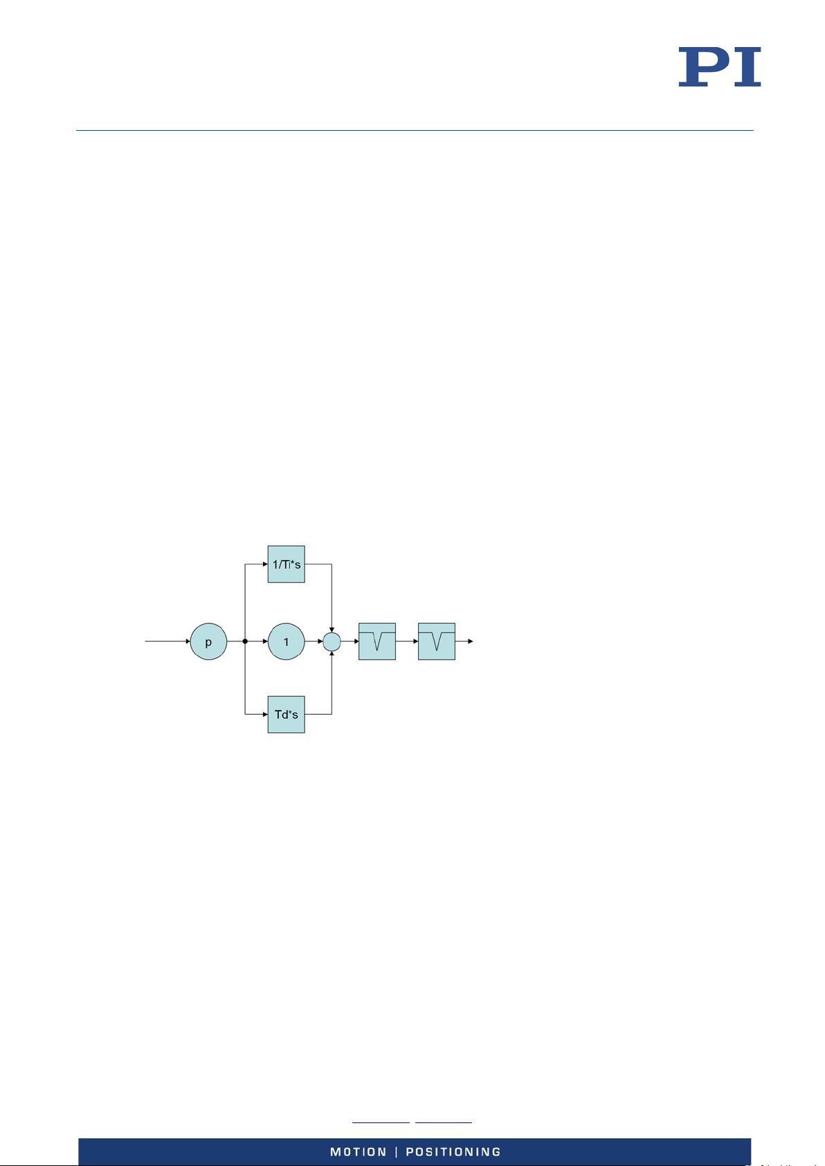
User Manual
E727T0005, valid for E-727
BRO, 2018-03-23
Control Details
Slew Rate Limitation
In closed-loop operation, the target signal can be manipulated by a slew rate limitation. For fastest
possible settling, the slew rate limitation can be switched off with the VCO command.
The slew rate limit for an axis is given by the Servo Loop Slew-Rate parameter (ID 0x07000200).
Control Algorithms
The control algorithm to be used in closed-loop operation can be selected for each axis via the
Closed-Loop Control Mode parameter (ID 0x07030100). Possible values of the parameter:
0 = None
1 = PID algorithm (position control)
Optional: 2 = Advanced Piezo Control (APC) algorithm, licence must be ordered separately, see
“Accessories” (p. 19)
With the PID algorithm, up to two notch filters can be used. The PID algorithm in principle has the
following structure:
Figure 13: Structure of the PID algorithm; two notch filters are available
Physik Instrumente (PI) GmbH & Co. KG, Auf der Roemerstrasse 1, 76228 Karlsruhe, Germany Page 35 / 228
Phone +49 721 4846-0, Fax +49 721 4846-1019, Email [email protected], www.pi.ws
Page 36
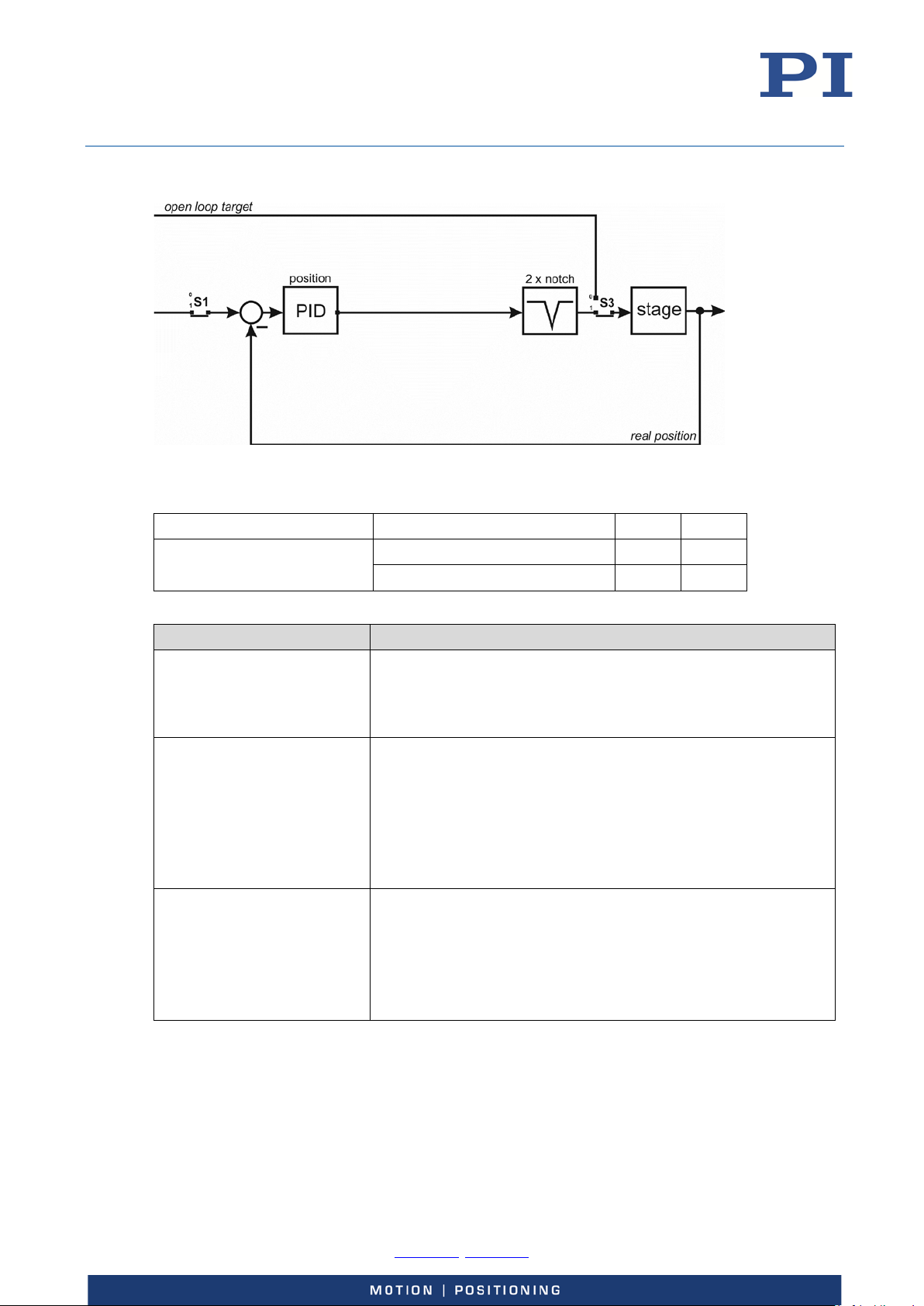
User Manual
Control mode
Servo-control state
S1
S3
Servo-Loop P-Term,
P constant for position control
Servo-Loop I-Term,
Integrator time constant Ti for position control
Servo-Loop D-Term,
Differentiator time constant Td for position control
E727T0005, valid for E-727
BRO, 2018-03-23
Position control (parameter value = 1):
Figure 14: Control structure for position control (mode 1). Here it is assumed that the notch filters are
disabled in open-loop operation (default setting of the Enable Notch In Open-Loop parameter).
Position control (mode 1) Open-loop operation 0 0
Closed-loop operation 1 1
The PID algorithm can be configured with the following parameters:
Parameter Notes
ID 0x07000300
ID 0x07000301
ID 0x07000302
Must be > 0.
For further details, see “Servo-Controller Dynamic Tuning”
(p. 125).
output = Ts / Ti ∙ ∑ input
where Ts is the servo update time (parameter 0x0E000200).
When the time constant Ti is zero, then the integrator is turned
off.
For further details, see “Servo-Controller Dynamic Tuning”
(p. 125).
output = Td / Ts ∙ Δinput
where Ts is the servo update time (parameter 0x0E000200).
Must be > 0.
For further details, see “Servo-Controller Dynamic Tuning”
(p. 125).
Physik Instrumente (PI) GmbH & Co. KG, Auf der Roemerstrasse 1, 76228 Karlsruhe, Germany Page 36 / 228
Phone +49 721 4846-0, Fax +49 721 4846-1019, Email [email protected], www.pi.ws
Page 37
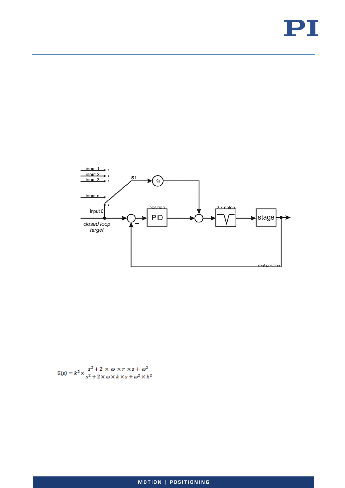
User Manual
E727T0005, valid for E-727
BRO, 2018-03-23
Feedforward
In closed-loop operation, for positioning systems with piezo actuators the main component
regarding the tracking error (tracking error = commanded position – real position) is the phase
shift between the commanded position and the real position. By adding a feedforward signal to
the control algorithm this phase shift can be reduced.
For every axis, an input signal channel of the controller can be selected as feedforward signal using
the Feed Forward Input Channel Index parameter (ID 0x07030900; S1 in the figure below). This
way, an external preshaping sequence can be used to compensate for a known error, for example.
If no input signal channel is selected, the target signal is used as feedforward signal (value of
parameter 0x07030900 is zero).
The feedforward signal is fed in before the notch filters to avoid exciting the resonances of the
system.
Figure 15: Control structure for position control with feedforward signal
For every axis, the usage of the feedforward signal can be configured using the Feedforward Gain
parameter (ID 0x07030600).
Notch Filters
The E-727 provides two notch filters per axis. The corrections by a notch filter only take place in
closed-loop operation by default, but can also be enabled for open-loop operation. The
appropriate frequency component is reduced in the control value to compensate for undesired
resonances in the mechanics.
The transfer function of a notch filter is as follows:
Where
G(s) is the transfer function of the notch filter
k is the bandwidth of the notch filter
s is the input signal
ω is the angular frequency, with ω = 2*π*f0, where f0 is the notch filter frequency in Hz
r is the notch rejection
Physik Instrumente (PI) GmbH & Co. KG, Auf der Roemerstrasse 1, 76228 Karlsruhe, Germany Page 37 / 228
Phone +49 721 4846-0, Fax +49 721 4846-1019, Email [email protected], www.pi.ws
Page 38
User Manual
Notch frequency 2
the rejection value, the wider the frequency spectrum of the damping,
Notch Rejection 2
Enable Notch in Open
Enables usage of notch filter in open-loop operation. In closed-loop
Notch Filter
0 = bilinear
E727T0005, valid for E-727
BRO, 2018-03-23
The notch filters can be configured using the following parameters:
Parameter Notes
Notch frequency 1
ID 0x08000100
ID 0x08000101
Notch Rejection 1
ID 0x08000200
ID 0x08000201
Frequency f0 of notch filter 1 and notch filter 2, in Hz.
The maximum value is:
= 0.45*f
f
0max
where f
sample
sample
is the servo rate in Hz (1/Servo Update Time (ID
0x0e000200))
Adjusting the notch filter frequency can be useful, particularly in the
case of very high loads. For further details, see “Adjusting the Notch
Filter(s) in Open-Loop Operation” (p. 130).
Notch rejection value r for notch filter 1 and notch filter 2.
0 to 0.98
Recommended value is 0.05. A notch rejection value of 1 deactivates
the notch filter.
The notch rejection value determines the filter width of the notch
filter, i.e. it scales the damping done by the notch filter: The greater
Notch Bandwidth 1
ID 0x08000300
Notch Bandwidth 2
ID 0x08000301
Creep factor T1/sec
ID 0x08000400
Creep factor T2/sec
ID 0x08000401
Loop
ID 0x08000500
Calculation Method
ID 0x08000600
but the smaller the damping effect.
Bandwidth k of notch filter 1 and notch filter 2
≥ 0.1
The notch filter bandwidth determines the effect of the low-pass
filtering: The smaller the bandwidth, the smaller the low-pass filter
frequency.
Currently not used; provided for future applications.
operation, the notch filters are always enabled.
0 = disable notch filter in open-loop operation (default)
1 = enable notch filter in open-loop operation
1 = zero-order hold
2 = frb (rejection rate is independent of bandwith)
Physik Instrumente (PI) GmbH & Co. KG, Auf der Roemerstrasse 1, 76228 Karlsruhe, Germany Page 38 / 228
Phone +49 721 4846-0, Fax +49 721 4846-1019, Email [email protected], www.pi.ws
Page 39
User Manual
When you connect a stage when the controller is powered on, the ID-chip of the stage is not read
E727T0005, valid for E-727
BRO, 2018-03-23
ID Chip Detection
The piezo stage which is connected to the E-727 may contain an ID-chip (located in the stage
connector). The following data is stored in the ID-chip (and cannot be modified there by the
customer):
Stage type
Serial number of the stage
Calibration data
Servo-control data (dynamic tuning, load dependent)
When a stage with ID-chip is connected to the controller for the first time, the stage parameters
from the ID-chip will be written to nonvolatile and volatile memory upon controller power-on or
reboot. Afterwards, the complete set of ID-chip parameters will be overwritten on power-on or
reboot only if the Power Up Read ID-Chip option is enabled via the corresponding parameter (ID
0x0f000000) for all input signal channels associated with the stage. By default, this option is
disabled to facilitate maintaining optimized parameter settings on the controller.
INFORMATION
by the controller. To read the ID-chip data, the controller must be power-cycled or rebooted using
the RBT command or the corresponding host software functions.
A piezo stage can be easily exchanged due to the functionality of the ID-chip. For further details,
see p. 125.
Overtemp Protection
INFORMATION
E-727 is equipped with a fan that is automatically switched on when necessary.
A sensor detects the internal temperature of the E-727. Based on the values measured by the
sensor, the E-727 supports the following temperature thresholds for overtemp protection of the
amplifier:
E-727.xxxP and .xxxAP models for higher output current only: Temperature
threshold 1 (“alert threshold”): 66 °C
All E-727 models: Temperature threshold 2 (“switch-off threshold”): 72 °C
If the sensor value exceeds threshold 2, the amplifier output is switched off automatically, and all
axes are switched to open-loop control.
Use the DIA? command to query if a threshold is exceeded and if the amplifier output is active.
Possible measures to avoid overheating:
Observe the installation instructions (p. 46).
With high output power, keep the ambient temperature below 35 °C.
If the sensor value exceeds threshold 1: Reduce the output power of the E-727 by
reducing the frequency and/or the amplitude in dynamic operation. Ensure
adequate ventilation.
If the sensor value exceeds threshold 2: Stop the wave generator. Let the system
cool down. Ensure adequate ventilation.
Physik Instrumente (PI) GmbH & Co. KG, Auf der Roemerstrasse 1, 76228 Karlsruhe, Germany Page 39 / 228
Phone +49 721 4846-0, Fax +49 721 4846-1019, Email [email protected], www.pi.ws
Page 40
User Manual
PC software
Operating
Short description
Recommended
Dynamic
Windows,
Allows software programming for the E-
For users who would like to use a
Merge Tool
Windows
The Merge Tool allows you to combine
For users who want to operate
PIMikroMove
Windows
Graphic user interface for Windows with
The system can be started without
For users who want to perform
E727T0005, valid for E-727
BRO, 2018-03-23
Overview of PC Software
The following table shows the PC software that is included in the product CD. The given operating
systems stand for the following versions:
Windows: Windows 7, 8 and 10 (32 bit, 64 bit)
Linux: Kernel 2.6, GTK 2.0, glibc 2.4 (configuration used to develop the PC software)
program
library for GCS
Drivers for
use with NI
LabVIEW
software
for use with
drivers for NI
LabVIEW
software
MATLAB
drivers
system
Linux
Windows,
Linux
Windows MATLAB is a development environment
727 with programming languages such as
e. g. C++. The functions in the dynamic
program library are based on the PI
General Command Set (GCS).
NI LabVIEW is a software for data
acquisition and process control (must be
ordered separately from National
Instruments). The E-727 software is a
collection of virtual instrument drivers (VI
drivers) for the E-727 controller.
In addition to the product-specific drivers,
the product CD also contains the Analog
drivers, a collection of drivers for
generating an analog control signal; see
"Performing the Initial Installation" (p. 42).
The drivers support the PI General
Command Set.
product-specific drivers from PI with each
other.
and programming language for numerical
calculations (must be ordered separately
from MathWorks).
The PI MATLAB driver consists of a
MATLAB class that can be included in any
MATLAB script. This class supports the PI
General Command Set.
The PI MATLAB driver does not require
any additional MATLAB toolboxes.
use
dynamic program library for their
application.
Is required for PIMikroMove.
Is required for the drivers for NI
LabVIEW software.
For users who want to use NI
LabVIEW to program their
application.
several products from PI at the
same time while using NI
LabVIEW.
For users who want to use
MATLAB to program their
application.
Physik Instrumente (PI) GmbH & Co. KG, Auf der Roemerstrasse 1, 76228 Karlsruhe, Germany Page 40 / 228
Phone +49 721 4846-0, Fax +49 721 4846-1019, Email [email protected], www.pi.ws
which the E-727 and other controllers
from PI can be used:
simple automation tasks or test
their equipment before or instead
of programming an application. A
Page 41
User Manual
PC software
Operating
Short description
Recommended
programming effort
log window showing the
PITerminal
Windows
Terminal program that can be used for
For users who want to send GCS
PI Update
Windows
Checks the PI software installed on the PC.
For users who want to update the
E727T0005, valid for E-727
BRO, 2018-03-23
system
Graph of motions in open-loop and closedloop operation
Macro functionality for storing command
sequences on the PC (host macros)
Support of HID devices
Complete environment for command
entry, for trying out different commands
No command knowledge is necessary to
operate PIMikroMove. PIMikroMove uses
the dynamic program library to supply
commands to the controller.
To provide the Device Parameter
Configuration window, PIMikroMove
requires the NI LabVIEW Run-Time Engine;
see "Performing the Initial Installation"
(p. 42).
nearly all PI controllers (see the
description of the Command Entry
window in the PIMikroMove user manual).
use
commands sent makes it possible
to learn how to use the
commands.
commands directly to the
controller.
Finder
PI Firmware
Update
Wizard
USB driver Windows Driver for the USB interface For all users.
If more current versions of the PC
software are available on the PI server,
downloading is offered.
Windows Program for user support when updating
firmware of the E-727.
PC software.
For users who want to update the
firmware.
Physik Instrumente (PI) GmbH & Co. KG, Auf der Roemerstrasse 1, 76228 Karlsruhe, Germany Page 41 / 228
Phone +49 721 4846-0, Fax +49 721 4846-1019, Email [email protected], www.pi.ws
Page 42

User Manual
E727T0005, valid for E-727
BRO, 2018-03-23
Installation
General Notes on Installation
Install the E-727 near the power source so that the power plug can be quickly and easily
disconnected from the mains.
Installing the PC Software
Performing the Initial Installation
Only use cables and connections that meet local safety regulations.
The communication between the E-727 and a PC is necessary to configure the E-727 and send
motion commands using the commands of the GCS. Various PC software applications are available
for this purpose.
Accessories
PC with a Windows operating system (7, 8, 10) or Linux operating system
Product CD (included in the scope of delivery)
Important information on the procedure for installation on Windows
Before you start installing the PC software on a PC with a Windows operating system (p. 44),
read the following information.
Physik Instrumente (PI) GmbH & Co. KG, Auf der Roemerstrasse 1, 76228 Karlsruhe, Germany Page 42 / 228
Phone +49 721 4846-0, Fax +49 721 4846-1019, Email [email protected], www.pi.ws
Page 43
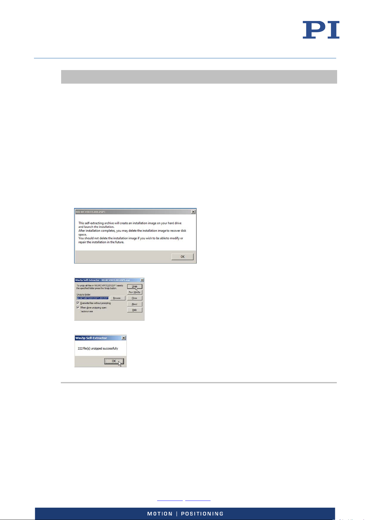
User Manual
E727T0005, valid for E-727
BRO, 2018-03-23
INFORMATION
When PIMikroMove is installed (default installation):
To provide the Device Parameter Configuration window, PIMikroMove requires the NI LabVIEW
Run-Time Engine. The installation of PIMikroMove therefore includes the installation of the NI
LabVIEW Run-Time Engine. A separate window opens for the installation of the NI LabVIEW RunTime Engine in addition to the InstallShield Wizard window.
The InstallShield Wizard interrupts the installation of the PC software for the E-727 until the
installation of the NI LabVIEW Run-Time Engine is started in the separate window.
Note that the separate window can be covered by the InstallShield Wizard window on the
screen. If necessary, display the separate window (e.g. by moving the InstallShield Wizard
window).
Follow the instructions for installing the NI LabVIEW Run-Time Engine that appear in the
separate window (see figures below):
Note that the files needed for installation have to be unpacked first. This does not complete
the installation though; you have to continue according to the instructions in the separate
window.
Agree to unpacking with OK
Start unpacking with Unzip
Finish unpacking with OK
Physik Instrumente (PI) GmbH & Co. KG, Auf der Roemerstrasse 1, 76228 Karlsruhe, Germany Page 43 / 228
Phone +49 721 4846-0, Fax +49 721 4846-1019, Email [email protected], www.pi.ws
Page 44
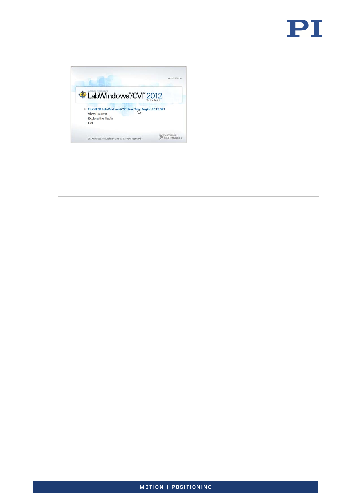
User Manual
E727T0005, valid for E-727
BRO, 2018-03-23
Start the installation of the NI LabVIEW Run-Time Engine with Install NI LabWindows/CVI
Run-Time Engine 2012 SP1
Note that the installation of the NI LabVIEW Run-Time Engine can take some time.
If you accidently close the separate window before the NI LabVIEW Run-Time Engine has been
successfully installed: Go to the \SingleSetups directory on the product CD and start the
installation by double-clicking the NI_LabWindows-CVI-RTE_2012_SP1_Setup.exe file.
Installing the PC software on Windows
1. Read "Important information on the procedure for installation on Windows" (p. 42).
2. Start the installation wizard by double-clicking the PI_E-727.CD_Setup.exe file in the
installation directory (main directory of the CD).
The InstallShield Wizard window for the installation of programs and manuals for the E-727
opens.
3. Follow the instructions on the screen.
You can choose between default installation (Complete) and user-defined installation
(Custom).
With default installation (recommended), all components are installed. These include among
others:
− Driver for use with NI LabVIEW software
Exception: The Analog drivers component is provided for some PI controllers.
This component is only available through user-defined installation.
− Dynamic program library for GCS
− PIMikroMove
− PC software for updating the firmware of the E-727
− PI Update Finder for updating the PC software
− For controllers that have a USB interface for communication with the PC: USB
drivers
With user-defined installation, you have the option of excluding individual components from
the installation.
Physik Instrumente (PI) GmbH & Co. KG, Auf der Roemerstrasse 1, 76228 Karlsruhe, Germany Page 44 / 228
Phone +49 721 4846-0, Fax +49 721 4846-1019, Email [email protected], www.pi.ws
Page 45

User Manual
E727T0005, valid for E-727
BRO, 2018-03-23
Installing the PC software on Linux
1. Unpack the tar archive from the /linux directory of the product CD to a directory on your PC.
2. Open a terminal and go to the directory to which you have unpacked the tar archive.
3. Log on as a superuser (root rights).
4. Enter ./INSTALL to start the installation.
Pay attention to lower and upper case when entering commands.
5. Follow the instructions on the screen.
You can select individual components for installation.
Installing Updates
PI is constantly improving the PC software.
Always install the latest version of the PC software.
Prerequisite
Active connection to the Internet.
If your PC uses a Windows operating system:
− You have installed the PI Update Finder from th product CD (p. 42).
− You have the A000T0028 Technical Note for the PI Update Finder at hand. You
− If the PC to be updated is not directly connected to the Internet:
If your PC uses a Linux operating system:
− You have the user name and password for the E-727 at hand. See the
Updating the PC software on Windows
can find the document on the product CD.
You have the A000T0032 Technical Note for the PI Update Finder at hand. You
can find the document on the product CD.
instructions on p. 10 for how to obtain the access data.
Use the PI Update Finder:
− When the PC to be updated is directly connected to the Internet: Follow the
instructions in the A000T0028 Technical Note
(TECHNICAL_NOTE_PI_UPDATE_FINDER_xx.pdf).
− When the PC to be updated is not directly connected to the Internet: Follow the
Physik Instrumente (PI) GmbH & Co. KG, Auf der Roemerstrasse 1, 76228 Karlsruhe, Germany Page 45 / 228
Phone +49 721 4846-0, Fax +49 721 4846-1019, Email [email protected], www.pi.ws
instructions in the A000T0032 Technical Note .
Page 46
User Manual
E727T0005, valid for E-727
BRO, 2018-03-23
Updating the PC software on Linux
INFORMATION
If software is missing or problems occur with downloading:
Contact our customer service department (p. 227).
1. Open the website www.pi.ws.
2. Log in with the access data for E-727 (user name, password).
3. Click Search.
4. Enter the product code up to the period (“E-727”) into the search field.
5. Click Start search or press the Enter key.
6. Open the corresponding product detail page in the list of search results:
a) If necessary: Scroll down the list.
b) If necessary: Click Load more results at the end of the list.
c) Click the corresponding product in the list.
7. Scroll down to the Downloads section on the product detail page.
The “CD Mirror” archive file is displayed under Software Files.
8. Copy the “CD Mirror” archive file to your PC.
9. Unpack the archive file to a separate installation directory.
10. In the directory with the unpacked files, go to the linux subdirectory.
11. Unpack the archive file in the linux directory by entering the command tar -xvpf <name of the
archive file> on the console.
12. Read the accompanying information on the software update (readme file and/or
"xxx_Releasenews.pdf" file) and decide whether the update makes sense for your application.
− If no: Stop the update procedure.
− If yes: Perform the following steps.
13. Log onto the PC as a superuser (root rights).
14. Install the update.
Ensuring Ventilation
Only a correct installation as described below will ensure correct operation of the E-727. To avoid
overheating of the E-727:
Set up the E-727 so that all ventilation holes in the housing are freely accessible.
Ensure adequate ventilation at the place of installation.
Keep the ambient temperature to a non-critical level (< 40 °C).
E-727.xxx, .xxxA, .xxxF and .xxxAF models:
− Allow at least 10 cm clearance from the top and rear, and a clear space of at
least 15 cm from the sides of the E-727. If this is not possible, make sure that the
place of installation is cooled sufficiently.
E-727.xxxP and .xxxAP models for higher output current:
− Allow at least 2 cm clearance from the sides and top, and a clear space of at
Physik Instrumente (PI) GmbH & Co. KG, Auf der Roemerstrasse 1, 76228 Karlsruhe, Germany Page 46 / 228
Phone +49 721 4846-0, Fax +49 721 4846-1019, Email [email protected], www.pi.ws
Page 47
User Manual
Observe the applicable standards for mounting the protective earth conductor.
E727T0005, valid for E-727
BRO, 2018-03-23
least 15 cm x 15 cm x 15 cm from the rear of the E-727.
− Do not remove the rubber feet from the bottom of the E-727 if you use it as a
benchtop device. The rubber feet ensure that the ventilation holes in the
bottom of the E-727 act as the air intake for convective cooling of internal
components (except for the amplifiers).
− If you place the E-727 in a rack: Remove the rubber feet from the bottom of the
E-727 only if the rack ensures that the ventilation holes in the bottom of the E-
See also “Overtemp Protection” (p. 39).
Connecting the E-727 to the Protective Earth Conductor
INFORMATION
727 act as the air intake for convective cooling.
Prerequisite
You have read and understood the Safety precautions (p. 11).
The E-727 is switched off via the Power switch.
Tools and accessories
Suitable protective earth conductor:
− Cable cross-section ≥0.75 mm
− Contact resistance < 0.1 ohm at 25 A at all connection points relevant for
mounting the protective earth conductor
Fastening material for the protective earth conductor (M4 screw, two safety
washers, two flat washers), sits on the protective earth connection (M4 hole) upon
delivery of the E-727 (p. 14).
2
Connecting the E-727 to the protective earth conductor
1. If necessary, fasten a suitable cable lug to the protective earth conductor.
2. Remove the M4 screw with the washers from the E-727.
3. Put the washers and the cable lug of the protective earth conductor on the M4 screw in the
following order:
− Safety washer
− Flat washer
− Cable lug
− Flat washer
− Safety washer
4. Insert the M4 screw into the protective earth connection hole of the E-727.
5. Tighten the M4 screw with at least three rotations and a torque of 1.2 Nm to 1.5 Nm.
Physik Instrumente (PI) GmbH & Co. KG, Auf der Roemerstrasse 1, 76228 Karlsruhe, Germany Page 47 / 228
Phone +49 721 4846-0, Fax +49 721 4846-1019, Email [email protected], www.pi.ws
Page 48
User Manual
E727T0005, valid for E-727
BRO, 2018-03-23
Start-Up
This chapter is intended to enable you to start initial test motions of a stage that is connected to a
E-727 in the PIMikroMove PC software.
The start-up should comprise the following steps in the given order:
Starting the system in PIMikroMove (p. 50): Installation, power-on, communication
between E-727 and PC in PIMikroMove, configuration of PIMikroMove
Creating backup file for controller parameters (p. 52)
Executing test motions in open-loop operation (p. 53): First test of the function
General Notes on Start-Up
CAUTION
Risk of electric shock if the protective earth conductor is not connected!
If a protective earth conductor is not or not properly connected, dangerous touch voltages can
occur on the E-727 in the case of malfunction or failure of the system. If touch voltages exist,
touching the E-727 can result in serious injury or death from electric shock.
Connect the E-727 to a protective earth conductor before start-up (p. 47).
Do not remove the protective earth conductor during operation.
If the protective earth conductor has to be removed temporarily (e. g. in the case of
modifications), reconnect the E-727 to the protective earth conductor before starting it up
again.
NOTICE
Damage to the stage and the load from oscillations!
Unsuitable settings of the notch filter and the servo-control parameters of the E-727 can cause
the stage to oscillate. Oscillations can damage the stage and/or the load affixed to it.
If the stage is oscillating (unusual operating noise), immediately switch off the servo mode or
disconnect the E-727 from the power source.
Only switch on the servo mode after you have modified the settings of the notch filter and the
servo-control parameters of the E-727; see „Adjusting the Notch Filter(s) in Open-Loop
Operation“ (p. 130) and "Checking and Optimizing the Servo-Control Parameters" (p. 134).
Physik Instrumente (PI) GmbH & Co. KG, Auf der Roemerstrasse 1, 76228 Karlsruhe, Germany Page 48 / 228
Phone +49 721 4846-0, Fax +49 721 4846-1019, Email [email protected], www.pi.ws
Page 49
User Manual
SVO 1 1 2 1
E727T0005, valid for E-727
BRO, 2018-03-23
NOTICE
Damage to piezo tip/tilt systems with differential drive!
PI piezo tip/tilt systems with differential drive, such as S-334 models, provide motion in two axes
, θY). The motion is controlled by axes 1 and 2 of the E-727. If a third axis is provided by the E-
(θ
X
727, it is only used to give access to the fixed voltage (100 V) that is required by the differential
drive. A piezo tip/tilt system with differential drive can be damaged by oscillations when the servo
mode is switched on for axis 3 of the E-727.
Do not switch on the servo mode for axis 3 of the E-727.
Make sure that the Power Up Servo On Enable parameter (ID 0x07000800) has the value 0
(= servo mode is not automatically switched on) for axis 3 of the E-727.
Changing the piezo output voltage too fast can cause damage to a piezo tip/tilt system with
differential drive.
Make sure that for axes 1, 2 and 3 of the E-727, the velocity for rising and falling of the piezo
output voltage in open-loop operation is limited to a suitable value. The velocity is given by
the Open Loop Slew-Rate parameter (ID 0x07000201). For axes 1 and 2, the parameter value
should be set to the axis travel range in µrad (e.g., 50000 (µrad/s) with S-334). For axis 3, the
parameter value should be set to 100 (= 100 V/s).
When the E-727 is not used but is to remain switched on to ensure the temperature stability, the
piezo output voltages should be set to 0 V to increase the lifetime of the piezo ceramics. When a
third axis is present in the E-727, zeroing and restoring the piezo output voltages in wrong order
can cause damage to a piezo tip/tilt system with differential drive.
1. Because zeroing/restoring the piezo output voltages will cause motion of axes 1 and 2, make
sure that the axes can move safely.
2. Proceed as follows for zeroing the piezo output voltages when the E-727 is not used but is to
remain switched on:
a. Switch off the servo mode for axes 1 and 2; corresponding command:
SVO 1 0 2 0
b. Set the piezo output voltage to 0 V for axes 1 and 2; corresponding command:
SVA 1 0 2 0
c. Wait 1 second, or check the piezo output voltages for channels 1 and 2 by sending:
VOL? 1 2
d. When the piezo output voltages for channels 1 and 2 are 0 V, set the fixed voltage to 0 V
by sending the corresponding command for axis 3:
SVA 3 0
3. Proceed as follows for restoring the piezo output voltages when the E-727 is still switched on
and the piezo tip/tilt system is to be used again:
a. Set to piezo output voltage to 100 V for axis 3; corresponding command:
SVA 3 100
b. Wait 1 second, or check the piezo output voltage for channel 3 by sending:
VOL? 3
c. Switch on the servo mode for axes 1 and 2; corresponding command:
.
Physik Instrumente (PI) GmbH & Co. KG, Auf der Roemerstrasse 1, 76228 Karlsruhe, Germany Page 49 / 228
Phone +49 721 4846-0, Fax +49 721 4846-1019, Email [email protected], www.pi.ws
Page 50
User Manual
When you connect a stage when the controller is powered on, the ID-chip of the stage is not read
E727T0005, valid for E-727
BRO, 2018-03-23
INFORMATION
The E-727, the stage(s) and any adapter or adapter cable for the stage connection are supplied as
a pre-configured system.
If a connection assignment is given on the labels of the E-727 and/or stage(s) and/or
adapter/adapter cable, observe this assignment when connecting the stage(s).
INFORMATION
by the controller. To read the ID-chip data, the controller must be power-cycled or rebooted using
the RBT command or the corresponding host software functions.
INFORMATION
Pin 2 of the Digital I/O socket can be configured as Reset input, see p. 220 for details. The Reset
input works as follows:
If nothing is connected to pin 2, the signal level is HIGH (internal pull-up with 10 kohm
resistor) which means normal operation of the E-727.
If the signal level on the Reset input becomes LOW, the E-727 is rebooted.
Make sure that the configuration of pin 2 of the Digital I/O socket and the connected signal
comply with your application.
INFORMATION
The E-727 performance can be reduced directly after power on due to thermal instability.
Switch the E-727 on at least one hour before starting work.
If the E-727 is not used, but should remain switched on to ensure the temperature stability:
Make sure that the servo mode is switched off (open-loop operation) and the piezo output
voltage is set to 0 V. To set the piezo output voltage to 0 V, set the axis position to a
corresponding value with the SVA command.
Starting the System in PIMikroMove
Proceed as follows to start the E-727 with the stage(s) in PIMikroMove:
1. Install the following on the PC:
− The PC software and the USB drivers from the product CD
− Updates for PC software
Details see "Installing the PC Software" (p. 42).
2. Make sure that the Power switch of the E-727 is in the OFF position (0).
Physik Instrumente (PI) GmbH & Co. KG, Auf der Roemerstrasse 1, 76228 Karlsruhe, Germany Page 50 / 228
Phone +49 721 4846-0, Fax +49 721 4846-1019, Email [email protected], www.pi.ws
Page 51

User Manual
E727T0005, valid for E-727
BRO, 2018-03-23
3. Install the E-727:
− Observe the general information on installation (p. 42).
− Ensure the ventilation (p. 46).
− Connect the E-727 to the protective earth conductor (p. 47).
4. Connect the following to the E-727:
− The included wide-range-input power supply to the 24 VDC connection via the
− The stage(s) to the socket for the piezo stages. If necessary, use the adapter or
− The PC via the RS-232 interface (RS-232 panel plug) or via the USB interface (USB
5. Switch on the E-727:
a) Connect the power cord of the wide-range-input power supply to the power socket.
b) Put the Power switch of the E-727 in the ON position (|).
During the power-on/reboot sequence, the LEDs of the E-727 behave as follows:
− Phase 1: All LEDs are lit for up to 4 seconds.
− Phase 2: If the E-727 is configured to obtain the IP address for TCP/IP
− Phase 3: E-727 initializes parameters. The Servo LEDs are alternately lit, and all
included adapter.
adapter cable which was delivered with the system.
type B) or via the Ethernet interface (RJ45).
communication from a DHCP server (default setting), the E-727 is searching for
the DHCP server for a maximum duration of 15 seconds. During this period, the
OFL and Servo LEDs are alternately lit, and all other LEDs are off. (If no DHCP
server is found, the static IP address set with parameter ID 0x11000600 is used.)
other LEDs are off.
The power-on/reboot sequence is finished when the Power LED is continuously lit.
6. Start PIMikroMove on the PC.
7. When the power-on/reboot sequence of the E-727 is finished, establish communication
between the E-727 and the PC in PIMikroMove via RS-232 or USB or TCP/IP. Further details see
"Communication" (p. 55).
8. In the Start up axes step in PIMikroMove, execute the AutoZero procedure for all linear axes
of the stage(s) (details see "AutoZero Procedure" (p. 61)).
Note that starting AutoZero for rotation axes will fail and cause the error code 74 („No sensor
channel or no piezo channel connected to selected axis (sensor and piezo matrix)“).
9. In the Start up controller window, click Close.
The main window of PIMikroMove opens.
10. Optionally: Configure the PIMikroMove main window.
It is recommended to see the tab cards for axes, input signal channels and output signal
channels (see figure below). You can arrange them by dragging them with the left mouse
button pressed so that they become docked e.g. to the bottom border of the window.
On the Axes tab card, amongst others you can start axis motion. The channel tab cards show
the current values of the input signal channels (sensors, analog input) and output signal
channels (output voltages for piezo actuators, analog output).
Physik Instrumente (PI) GmbH & Co. KG, Auf der Roemerstrasse 1, 76228 Karlsruhe, Germany Page 51 / 228
Phone +49 721 4846-0, Fax +49 721 4846-1019, Email [email protected], www.pi.ws
Page 52
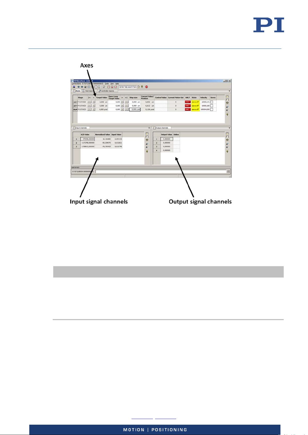
User Manual
The properties of the E-727 and the connected stage(s) are stored in the E-727 as parameter
E727T0005, valid for E-727
BRO, 2018-03-23
Note: The input and output signal channels of the E-727 are allocated to the logical axes via
matrices (input matrix: parameters 0x07000500 to 0x07000506; output matrix: parameters
0x09000000 to 0x09000003). Depending on the connected stage type, an axis may be driven
by more than one piezo actuator and measured by more than one sensor.
Creating Backup Files for Controller Parameters
INFORMATION
values.
Create a backup copy on the PC before changing the parameter values of the E-727. You can
then restore the original settings at any time.
Create an additional backup copy with a new file name each time after you optimize the
parameter values.
To save the parameter values and to load them back to the E-727, use the Device Parameter
Configuration window provided by PIMikroMove.
Proceed as follows to create a parameter file:
1. In the main window of PIMikroMove, open the Device Parameter Configuration window via
the E-727… > Parameter Configuration … menu item.
Physik Instrumente (PI) GmbH & Co. KG, Auf der Roemerstrasse 1, 76228 Karlsruhe, Germany Page 52 / 228
Phone +49 721 4846-0, Fax +49 721 4846-1019, Email [email protected], www.pi.ws
Page 53
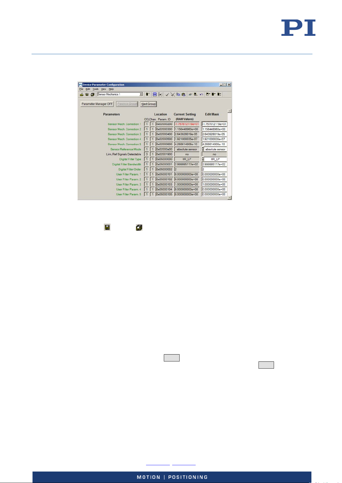
User Manual
E727T0005, valid for E-727
BRO, 2018-03-23
In the figure below, the Device Parameter Configuration window shows the Sensor
Mechanics 1 parameter group.
2. Save the parameter values from the Edit Mask column of the Device Parameter Configuration
window in a parameter file (file extension .pam) on your PC. Use one of the following options:
− File > Save Edit Values or File > Save Edit Values As menu item
(Save) or (Save As) button in the icon bar
−
Executing Test Motions in Open-Loop Operation
The first moves should be made in open-loop operation. With the factory default settings of the E727, open-loop commanding means to give open-loop values which correspond approximately to
axis positions.
1. In the main window of PIMikroMove, make some test moves with the individual axes using the
controls on the Axes tab card. During the test moves, observe the position display for the axes
(in the Current Value / Position fields) and the current output voltage(s) for the piezo
actuator(s) in the stage(s) (in the Output Value fields of the Output Channels tab card).
Proceed as follows for each linear axis (for rotation axes, the given open-loop values
correspond approximately to positions in µrad, and the step size can be set to a larger
value, for example 100 µrad):
a) Make sure that the Servo box is unchecked.
b) Command an open-loop value of 0 (µm) by entering 0 in the Open-Loop Target Value
field of the axis and pressing Enter on your keyboard.
c) Enter the value 10 (µm) in the Step size field of the axis and press Enter.
d) Use the > button next to the Open-Loop Target Value field to increment the
commanded value by the value given in the Step size field (10). Increment the openloop value this way step by step up to the upper travel range limit of the axis.
e) Use the < button next to the Open-Loop Target Value field to decrement the
commanded value by the value given in the Step size field (10). Decrement the openloop value this way step by step back to zero.
Physik Instrumente (PI) GmbH & Co. KG, Auf der Roemerstrasse 1, 76228 Karlsruhe, Germany Page 53 / 228
Phone +49 721 4846-0, Fax +49 721 4846-1019, Email [email protected], www.pi.ws
Page 54
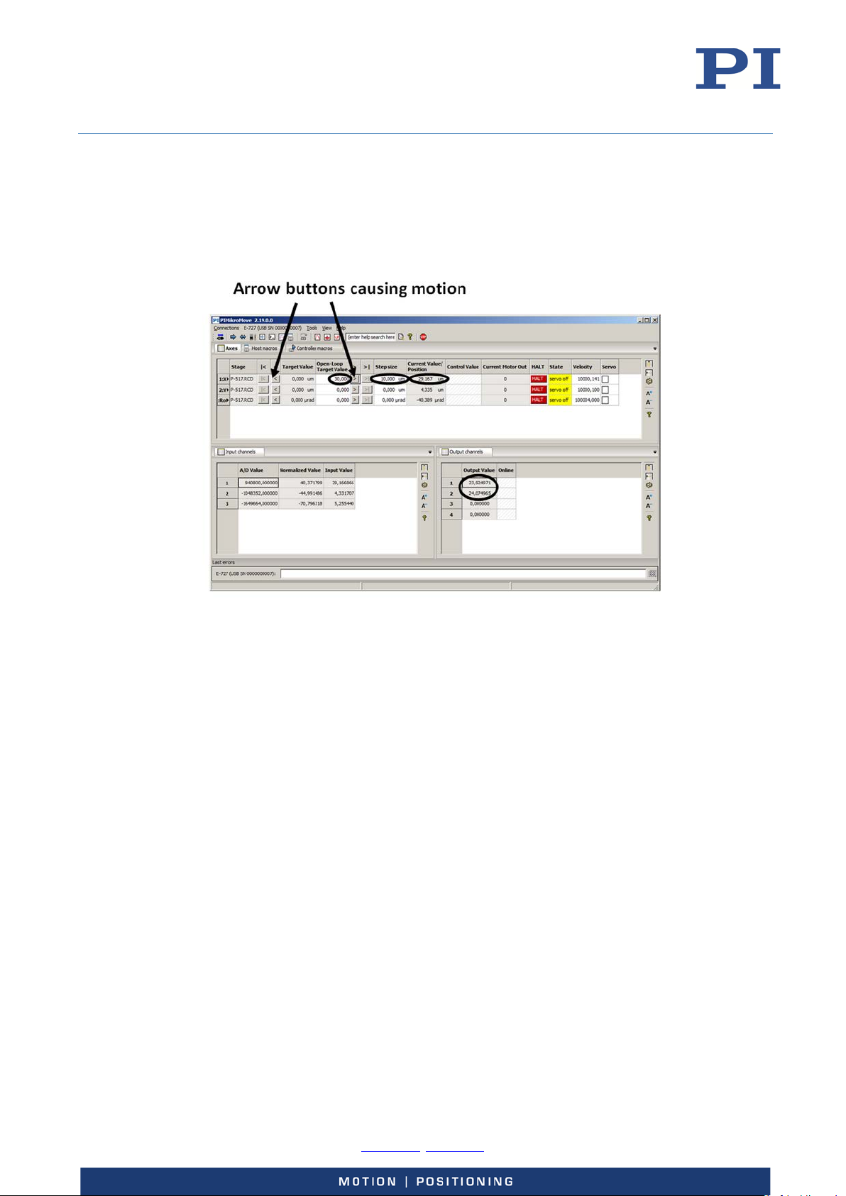
User Manual
E727T0005, valid for E-727
BRO, 2018-03-23
The values for position and output voltage should follow the commanded open-loop
values: The axis position should always correspond approximately to the commanded
value, and the output voltage(s) should become noticeably different from 0 V and then go
back to zero again during the procedure (with the E-727, the output voltage range is -30 to
+130 V; the output voltage(s) corresponding to a given open-loop value depend(s) on the
connected stage(s)).
In the example shown in the figure above, the open-loop value for axis 1 was increased to
30 by clicking the > button three times (step size value is 10). The current position
approximately corresponds to the commanded open-loop value (29.167 µm). Because
axis 1 of the stage is driven by two piezo actuators in the example, the output voltage of
the corresponding output signal channels 1 and 2 has changed to appropriate values.
2. Make open-loop frequency response measurements in the Piezo Dynamic Tuner window of
PIMikroMove to determine the resonant frequencies of the axes. See "Servo Controller
Dynamic Tuning" (p. 128) for more information.
If there are resonances which are intolerable in your application:
− Adjust the notch filter settings for the axis before you switch to closed-loop operation
for the first time (servo on). Furthermore, it might be necessary to readjust the preset
servo parameters for the axis.
Physik Instrumente (PI) GmbH & Co. KG, Auf der Roemerstrasse 1, 76228 Karlsruhe, Germany Page 54 / 228
Phone +49 721 4846-0, Fax +49 721 4846-1019, Email [email protected], www.pi.ws
Page 55
User Manual
window in PIMikroMove. There you can comfortably read, modify and save the values of
E727T0005, valid for E-727
BRO, 2018-03-23
Operation
Communication
PC Interfaces
The E-727 can be controlled with ASCII commands (PI General Command Set) from a PC via the
following communication interfaces:
TCP/IP (p. 55)
Serial RS-232 connection (p. 60; not present if an EtherCAT interface is available)
USB connection (p. 61)
With TCP/IP and USB connections, communication cannot be maintained after the E-727 is powercycled or rebooted, or when EtherCAT communication is no longer running and TCP/IP and USB are
enabled again. The TCP/IP or USB connection must then be closed and reopened.
INFORMATION
The following commands are available for the PC interface parameters of the E-727:
Values in the nonvolatile memory:
− Get with IFS?
− Set with IFS
Values in the volatile memory:
− Get with IFC?
− Set with IFC (baud rate for RS-232 only)
For querying and setting the interface parameters, it is recommended to use the Configure
Interface
the interface parameters. For details, see the PIMikroMove manual.
Additional Interfaces
In addition, the E-727 can be controlled by an SPI master, see “SPI Interface” (p. 138) for details.
The PC interfaces and the SPI interface can be active simultaneously. The commands from the
interfaces are queued in the order the completed command lines are received.
E-727 models with EtherCAT interface can also be controlled by an EtherCAT master, see
“EtherCAT Interface” (p. 158) for details. The PC interfaces are disabled when EtherCAT
communication is running (OPERATIONAL communication state).
Communication via the TCP/IP Interface
The TCP/IP settings of E-727 are preset as follows:
IP address (parameter ID 0x11000600): 192.168.168.10:50000
IP mask (parameter ID 0x11000700): 255.255.255.0
IP start (parameter ID 0x11000800): 1 (IP address is obtained from DHCP server; if
no DHCP server is present, the IP address defined with parameter 0x11000600 is
used as static address)
Physik Instrumente (PI) GmbH & Co. KG, Auf der Roemerstrasse 1, 76228 Karlsruhe, Germany Page 55 / 228
Phone +49 721 4846-0, Fax +49 721 4846-1019, Email [email protected], www.pi.ws
Page 56

User Manual
E727T0005, valid for E-727
BRO, 2018-03-23
Before communication is established, it can be necessary to adapt the interface parameters once,
depending on the type of networking.
Network with DHCP server: No adjustment of the factory settings of the interface
parameters of the E-727 is necessary
Network without DHCP server or direct connection (E-727 directly connected to the
Ethernet connection socket of the PC):
− The start-up behavior of the E-727 for configuring the IP address must be
− The IP addresses and subnet masks of the E-727 and PC as well as all other
See “Adaptation of the interface parameters” below for details.
When the IP address is obtained via DHCP server
You should be aware of the following: When a TCP/IP connection is established at which the IP
address is obtained from DHCP server, this address will automatically be written to the IP Address
parameter (ID 0x11000600) in the volatile memory of the E-727. When you save the current
settings to nonvolatile memory (e.g., with WPA 100) while the current command level is 1, the
obtained IP address will become the new default address of the E-727.
changed so that the E-727 uses a static address (set IP start to 0).
network participants must be adapted to each other (set IP address and IP mask
of E-727 to suitable values).
After switching on or rebooting the E-727
The starting procedure of the E-727 must be finished before the communication between the E727 and PC can be established. The starting procedure takes about 20 seconds and is finished
when the Power LED is continuously lit.
Connection of the network cable when the controller is switched on
Establishing communication via TCP/IP can fail if the network cable was connected to the RJ45
Ethernet socket on the front panel of the E-727 while the E-727 was switched on.
If the establishment of communication fails, switch the E-727 off and back on again while
the network cable is plugged in.
With E-727 firmware version 14.02.01.00 and newer (see response to *IDN?): The network cable
can be connected when the E-727 is switched on. The E-727 will start searching for the DHCP
server in the following cases:
You try to establish communication via TCP/IP in the PC software, e. g., in PIMikroMove or
PITerminal. Note that the E-727 may not be found at the first attempt. Try again after the
first attempt has failed.
E-727 models with EtherCAT interface: The PC interfaces are enabled again after stop of
EtherCAT communication (= the E-727 has left the OPERATIONAL communication state).
Port setting
For communication via TCP/IP, the E-727 only has a single unchangeable port (50000) available,
which cannot be used by more than one connection at a time.
Physik Instrumente (PI) GmbH & Co. KG, Auf der Roemerstrasse 1, 76228 Karlsruhe, Germany Page 56 / 228
Phone +49 721 4846-0, Fax +49 721 4846-1019, Email [email protected], www.pi.ws
Page 57

User Manual
E727T0005, valid for E-727
BRO, 2018-03-23
Adaptation of the interface parameters
The IP address and IP mask settings of PC and controller must be compatible with each other in the
following cases:
The E-727 is directly connected to an Ethernet connection of the PC.
E-727 and the host PC both are connected to the same network where no DHCP
server is available (in this case, the settings must also be compatible with those of
any other devices in the same network).
Otherwise no connection can be established. You can configure either the PC or the controller
settings to be compatible. If you have a network with multiple E-727, the settings of the individual
controllers must be changed to have unique IP addresses for all devices in the network. See below
for how to proceed.
If you want to change the PC settings:
Configure the connection on the PC according to the IP address and IP mask settings of the
controller (see above for the default controller settings). Note that the following steps may vary in
some details depending on the version of your Windows operating system:
1. Open the window in which the properties of the TCP/IP Internet protocol are displayed and
set, in a suitable way on your PC. The necessary steps depend on the operating system used.
If your operating system distinguishes between Internet protocol version 4 (TCP/IPv4)
and version 6 (TCP/IPv6), open the window for version 4.
2. In the Internet Protocol (TCP/IP) Properties window, activate Use the following IP address.
Make a note of the current IP address and Subnet mask settings, if any, in case they need to
be restored later. Then adapt the IP address and Subnet mask settings to make them
compatible with the settings of your E-727:
Set the first three portions of IP address identical to those of the IP address of the E727, while the last portion must be different. One possible IP address setting would be,
for example, 192.168.168.2 (the default IP address of the E-727 is 192.168.168.10). Do
not use "255" for the last portion.
Set Subnet mask to 255.255.255.0 (if the IP mask of the E-727 is 255.255.255.0).
Confirm with OK. An example is shown in the figure below.
3. Connect the E-727 to the Ethernet socket of the PC using the included, special, cross-over cable
("point-to-point" connection). If you connect the E-727 to a free access point (e.g. to a hub) on
a network to which the PC is connected, it might be necessary to use a straight-through
network cable.
4. Power on the E-727 system.
5. Establish the connection between PC and the E-727 as described below in "Establishing
communication via TCP/IP".
6. If the connection fails: Change the last portion of the IP address setting on the PC and try again
to connect.
Physik Instrumente (PI) GmbH & Co. KG, Auf der Roemerstrasse 1, 76228 Karlsruhe, Germany Page 57 / 228
Phone +49 721 4846-0, Fax +49 721 4846-1019, Email [email protected], www.pi.ws
Page 58
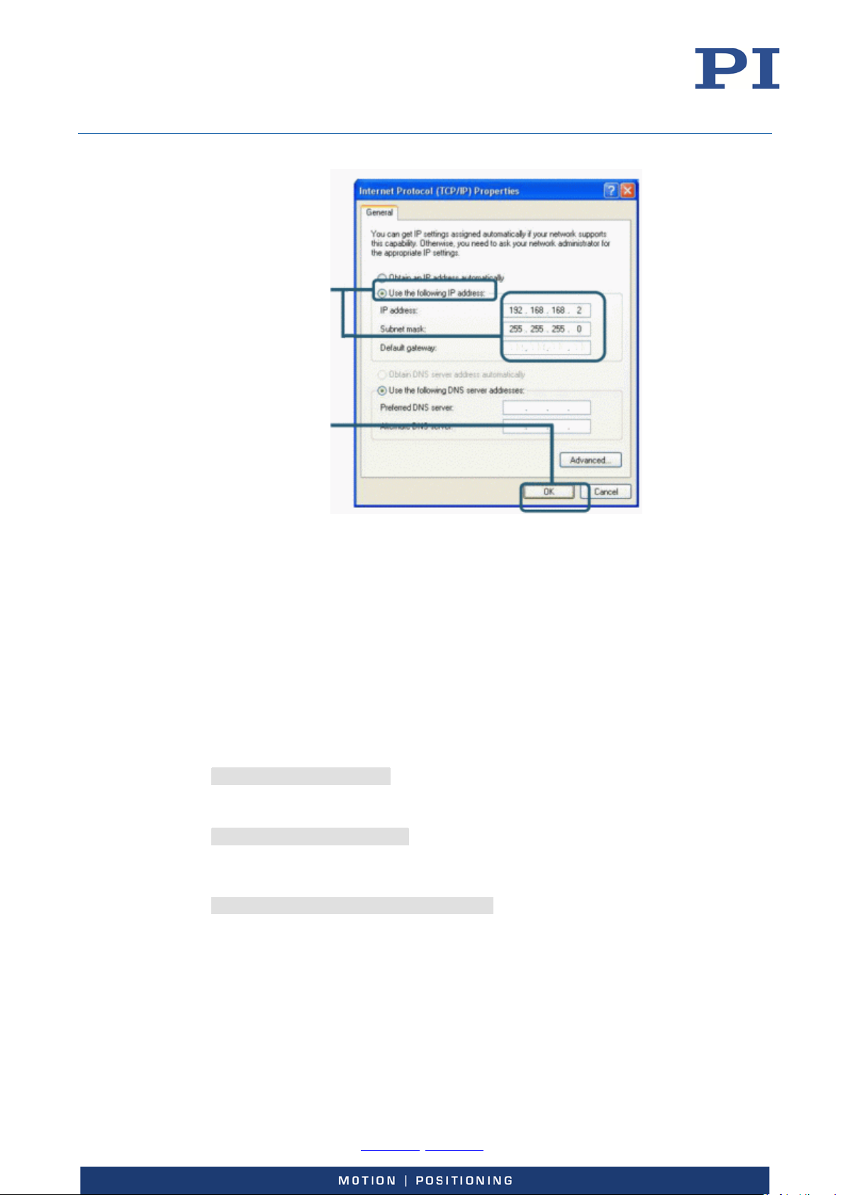
User Manual
E727T0005, valid for E-727
BRO, 2018-03-23
Adapt IP address and
Subnet mask; do not
change the Default
gateway setting
Press OK
Figure 16: Internet Protocol (TCP/IP) Properties
window, the settings shown are only
examples, maybe they do not match that
of your controller
If you want to change the controller settings:
1. Establish a serial connection between PC and E-727 as described in "Communication via the
RS-232 Interface" (p. 60).
2. Use the IFS command in the command entry facility of the program to adapt the IP address
and IP mask settings of the E-727 to those of the PC (to check the PC settings, you can open the
Internet Protocol (TCP/IP) Properties window as described above):
To change the IP mask, send
IFS 100 IPMASK mask
mask must be identical to the Subnet mask setting of the PC.
To change the IP address, send
IFS 100 IPADR address
address: At least the last portion of the IP address must be different from that of the PC
and any other device in the same network (the applicable address settings depend on
the IP mask setting). If, for example, the PC has the IP address 172.21.0.1, send
IFS 100 IPADR 172.21.0.2:50000
Do not use "255", and do not change the port setting (must always be 50000).
3. Close the connection.
4. Connect the E-727 to the Ethernet socket of the PC using the included, special, cross-over cable
("point-to-point" connection). If you connect the E-727 to a free access point (e.g. to a hub) on
a network to which the PC is connected, it might be necessary to use a straight-through
network cable.
Physik Instrumente (PI) GmbH & Co. KG, Auf der Roemerstrasse 1, 76228 Karlsruhe, Germany Page 58 / 228
Phone +49 721 4846-0, Fax +49 721 4846-1019, Email [email protected], www.pi.ws
Page 59
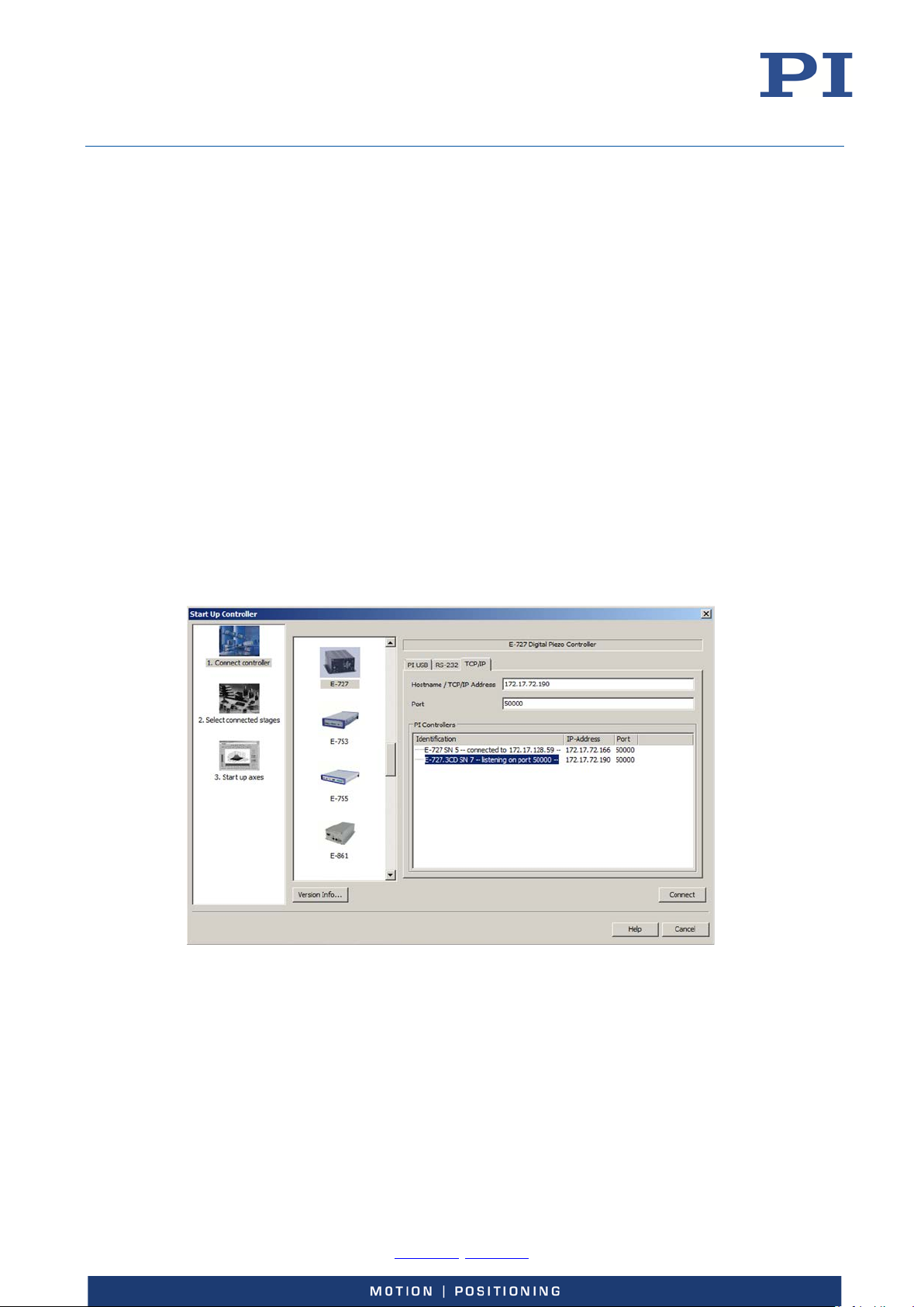
User Manual
E727T0005, valid for E-727
BRO, 2018-03-23
5. Power-cycle the E-727.
6. Establish the connection between PC and the E-727 as described in " Establishing
communication via TCP/IP" below.
Establishing communication via TCP/IP
The procedure for PIMikroMove is described in the following. The procedure for other PC software
programs (PITerminal, drivers for use with NI LabVIEW software) is similar.
1. Start PIMikroMove.
The Start up controller window opens with the Connect controller step.
− If the Start up controller window does not automatically open, select the
2. Select E-727 in the field for controller selection.
3. Select the TCP/IP tab on the right side of the window.
All E-727 controllers in the same network are listed in the PI Controllers field.
4. Click the PI E-727 … SN ... entry in the controller list (SN stands for serial number).
− If several PI E-727… SN ... entries are shown, identify your E-727 on the basis of
− If the E-727 is not displayed in the controller list, check the network settings.
Connections > New... menu item in the main window.
its nine-digit serial number.
Consult your network administrator if necessary.
Do not select a controller with which a connection via TCP/IP already exists. Otherwise, an
error message will be displayed as soon as you want to establish communication with this
controller.
5. Check the IP address in the Hostname / TCP/IP Address field and the port number in the Port
field.
6. Click the Connect button to establish communication.
If communication has been successfully established, the Start up controller window switches
to the Start up axes step.
Physik Instrumente (PI) GmbH & Co. KG, Auf der Roemerstrasse 1, 76228 Karlsruhe, Germany Page 59 / 228
Phone +49 721 4846-0, Fax +49 721 4846-1019, Email [email protected], www.pi.ws
Page 60
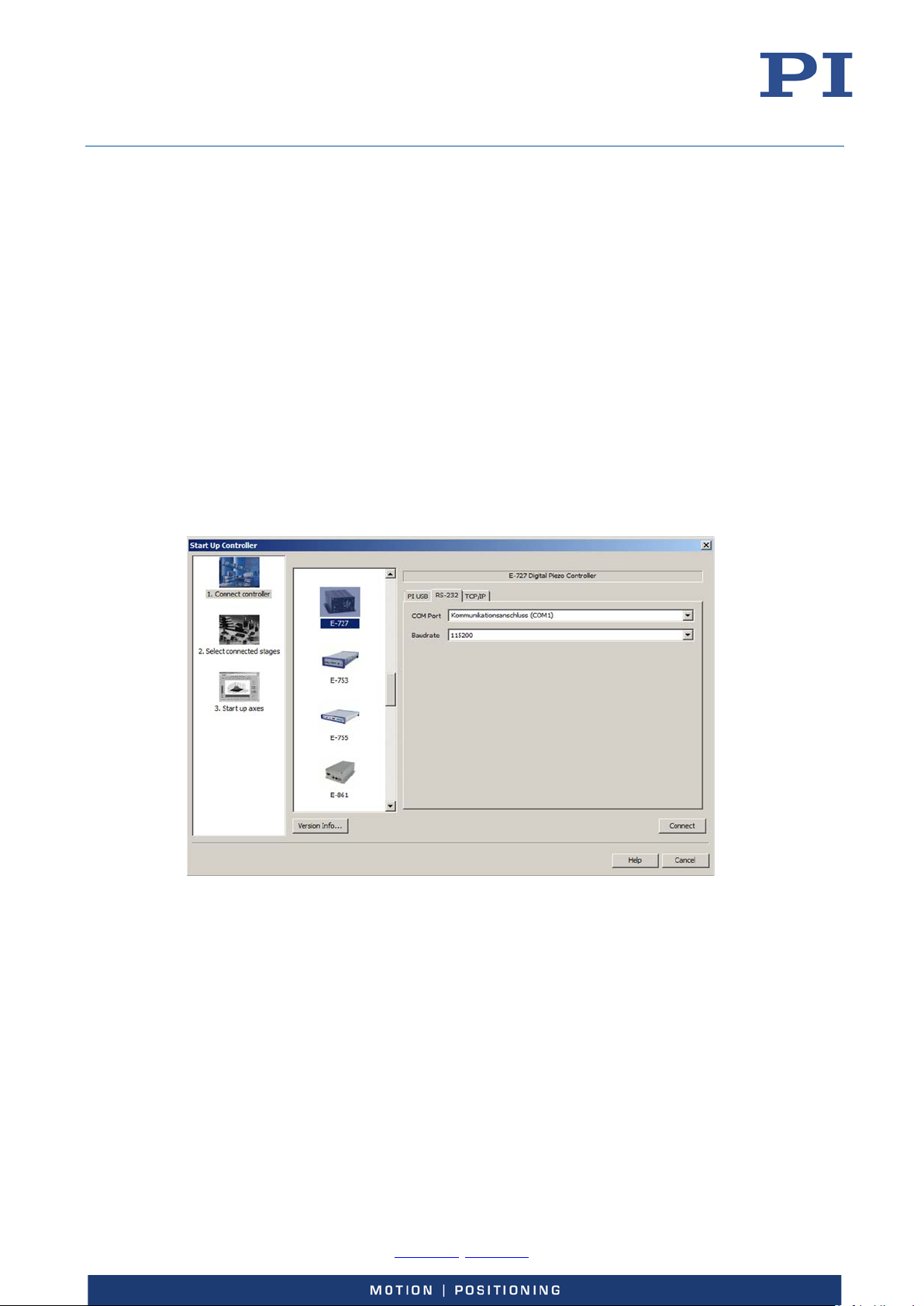
User Manual
E727T0005, valid for E-727
BRO, 2018-03-23
Communication via the RS-232 Interface
The baud rate of E-727 for RS-232 communication is preset as follows:
Uart baud rate (parameter ID 0x11000400): 115200
Further possible values are 9600, 19200, 38400, 57600.
To successfully establish communication, the baud rates of the E-727 and PC must match.
Establishing communication via RS-232
The procedure for PIMikroMove is described in the following. The procedure for other PC software
programs (PITerminal, drivers for use with NI LabVIEW software) is similar.
1. Start PIMikroMove.
The Start up controller window opens with the Connect controller step.
− If the Start up controller window does not automatically open, select the
Connections > New... menu item in the main window.
2. Select E-727 in the field for controller selection.
3. Select the RS-232 tab on the right side of the window.
4. In the COM Port field, select the COM port of the PC to which you have connected the E-727.
5. Set a suitable value in the Baudrate field to adapt the baud rate of the PC to the baud rate of
the E-727.
6. Click Connect to establish communication.
If communication has been successfully established, the Start up controller window switches
to the Start up axes step.
Physik Instrumente (PI) GmbH & Co. KG, Auf der Roemerstrasse 1, 76228 Karlsruhe, Germany Page 60 / 228
Phone +49 721 4846-0, Fax +49 721 4846-1019, Email [email protected], www.pi.ws
Page 61
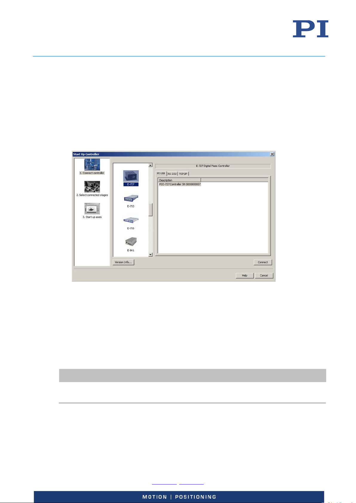
User Manual
E727T0005, valid for E-727
BRO, 2018-03-23
Communication via the USB Interface
Establishing communication via USB
The procedure for PIMikroMove is described in the following. The procedure for other PC software
programs (PITerminal, drivers for use with NI LabVIEW software) is similar.
1. Start PIMikroMove.
The Start up controller window opens with the Connect controller step.
− If the Start up controller window does not automatically open, select the
Connections > New... menu item in the main window.
2. Select E-727 in the field for controller selection.
3. Select the USB tab on the right side of the window.
4. On the USB tab, select the connected E-727.
5. Click Connect to establish communication.
If communication has been successfully established, the Start up controller window switches
to the Start up axes step.
AutoZero Procedure
INFORMATION
During the AutoZero procedure, the axis will move, and the motion can cover the whole travel
range.
Physik Instrumente (PI) GmbH & Co. KG, Auf der Roemerstrasse 1, 76228 Karlsruhe, Germany Page 61 / 228
Phone +49 721 4846-0, Fax +49 721 4846-1019, Email [email protected], www.pi.ws
Page 62
User Manual
E727T0005, valid for E-727
BRO, 2018-03-23
INFORMATION
AutoZero is to be performed with linear axes only. Starting AutoZero for rotation axes will fail and
cause the error code 74 („No sensor channel or no piezo channel connected to selected axis
(sensor and piezo matrix)“).
Objective and Prerequisites of AutoZero
The AutoZero procedure performs automatic zero point adjustment of the sensors.
Objective of AutoZero:
Make the entire travel range available:
Changes in temperature or changes in the mechanical load can cause small
deviations of the sensor zero point. When the sensor zero-point is set correctly, the
complete output voltage range of the amplifier can be used in closed-loop
operation.
Prevent the piezo actuators from damage:
In open-loop operation, the stage displacement with 0 V piezo voltage should
already be about 10 % of the travel range. Then the average applied voltage is
reduced which lengthens the lifetime of the piezo actuator in the stage without
reducing the nominal travel range.
Prerequisites for AutoZero:
LowVoltage < HighVoltage
(LowVoltage is given by the value of the AutoZero Low Voltage parameter (ID
0x07000a00);
HighVoltage is given by the value of the AutoZero High Voltage parameter (ID
0x07000a01))
The value of the AutoZero High Voltage parameter (ID 0x07000a01) should be
identical with the piezo voltage that is required for maximum displacement of the
axis.
Settings Changed by AutoZero
The AutoZero procedure changes the values of the parameters Sensor Mech. Correction 1 (ID
0x02000200). With the E-727.3RD and .3RDA models for piezoresistive sensors and the E-727.3SD
and .3SDA models for strain gauge sensors, the AutoZero procedure also changes Sensor Offset
factor (ID 0x02000102).
Starting AutoZero via Command Entry
Via command entry, you have the following options to start the AutoZero procedure of the E-727:
Use the ATZ command to perform the AutoZero procedure once (see E-725 user
manual (PZ197E) for ATZ details). Afterwards save the values of the parameters
Sensor Mech. Correction 1 (ID 0x02000200) and Sensor Offset factor (ID
0x02000102) to nonvolatile memory.
Send the ATZ command after every start or reboot of the E-727.
Set the value of the Power Up AutoZero Enable parameter (ID 0x07000802) to 1 for
all axes so that the AutoZero procedure is performed automatically with every start
or reboot of the E-727.
Physik Instrumente (PI) GmbH & Co. KG, Auf der Roemerstrasse 1, 76228 Karlsruhe, Germany Page 62 / 228
Phone +49 721 4846-0, Fax +49 721 4846-1019, Email [email protected], www.pi.ws
Page 63
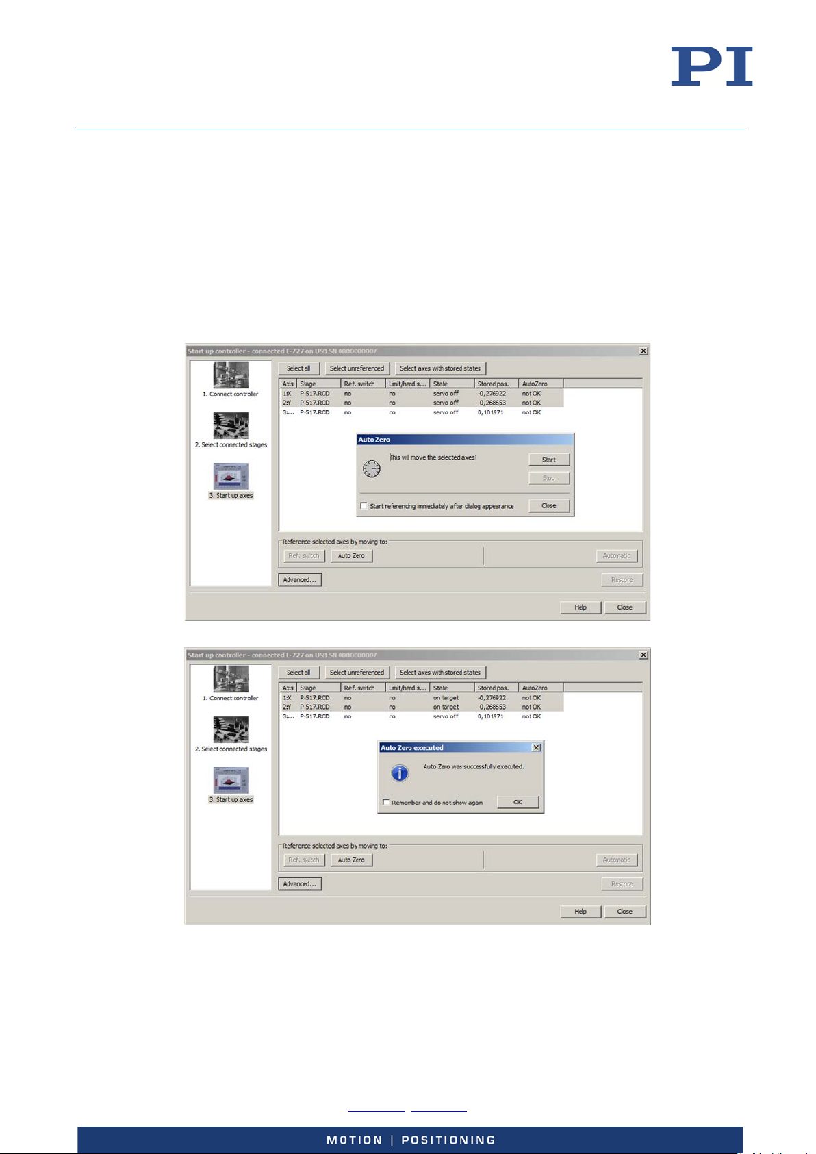
User Manual
E727T0005, valid for E-727
BRO, 2018-03-23
Starting AutoZero in PIMikroMove
In the Start up axes step of the Start up controller window, execute the AutoZero
procedure.
− To re-open the Start up controller window with the Start up axes step, select
the E-727 > Start up axes... menu item in the main window.
Proceed as follows for the linear axes that are connected:
a) Mark the linear axes in the list.
b) Click Auto Zero. The Auto Zero dialog opens.
c) In the Auto Zero dialog, start the AutoZero procedure by clicking Start.
d) After a successful AutoZero procedure, click OK.
Physik Instrumente (PI) GmbH & Co. KG, Auf der Roemerstrasse 1, 76228 Karlsruhe, Germany Page 63 / 228
Phone +49 721 4846-0, Fax +49 721 4846-1019, Email [email protected], www.pi.ws
Page 64
User Manual
With the default settings of the relevant parameters, sensor autoscaling is excluded from the
can apply to customized stages only).
E727T0005, valid for E-727
BRO, 2018-03-23
Starting AutoZero via EtherCAT Master
E-727 models with EtherCAT interface (p. 158): The AutoZero procedure is the only homing
method supported by the E-727. For details, see “Homing Mode” (p. 167).
In order for the EtherCAT master to be able to initiate a transition to the Ready to switch on state,
the AutoZero procedure must be finished.
Special Function: Sensor Autoscaling
Sensor autoscaling can be included in the AutoZero procedure, if necessary.
INFORMATION
AutoZero procedure:
Sensor Autoscaling Enable (ID 0x03003700): default value is 0
Sensor Autoscaling Gain (ID 0x03003701): default value is 1.0
Change the values of the parameters only if sensor autoscaling is necessary. Sensor
autoscaling is necessary only if all of the following conditions are met:
− The stage has no ID chip.
− The stage has piezoresistive or strain gauge sensors.
− PI has informed you that the stage design is suitable for sensor autoscaling (currently, this
Objective of sensor autoscaling:
Ensure the replaceability of stage(s) and controller:
For optimum sensor scaling, the sensor gain setting of the controller has to be
adapted to the connected stage.
Prerequisites:
If autoscaling of a sensor is to be included in the AutoZero procedure: The Sensor
Autoscaling Enable parameter (ID 0x03003700) must be set to the value 1 for that
sensor.
Sensor autoscaling setting changed by AutoZero:
If the Sensor Autoscaling Enable parameter (ID 0x03003700) has the value 1, the AutoZero
procedure changes the Sensor Autoscaling Gain (ID 0x03003701) for the corresponding sensor
channel (in addition to the settings mentioned on p. 62).
Data Recording
How to Use the Data Recorder
The E-727 includes a real-time data recorder. It is able to record several input and output signals
(e.g. current position, sensor input, output voltage) from different data sources (e.g. controller
axes, input and output channels, digital inputs and outputs). The gathered data is stored
(temporarily) in "data recorder tables"—each table contains the signal from one data source. You
Physik Instrumente (PI) GmbH & Co. KG, Auf der Roemerstrasse 1, 76228 Karlsruhe, Germany Page 64 / 228
Phone +49 721 4846-0, Fax +49 721 4846-1019, Email [email protected], www.pi.ws
Page 65
User Manual
E727T0005, valid for E-727
BRO, 2018-03-23
can configure the data recorder flexibly, e.g. select the type of data and the data source.
Furthermore, you can choose the number of record tables and hence influence their size.
For general information regarding the data recording you can send HDR?, which lists available
options, and gives information about additional parameters and commands concerned with data
recording.
How to Define What to Record—Set Record Options
The data recorder configuration, i.e. the assignment of data sources and record options to the
recorder tables, can be read with the DRC? command. The answer gives the values of the
parameters DRC Data Source (ID 0x16000700) and DRC Record Option (ID 0x16000701). Use the
DRC command or change the parameter values directly in volatile memory. The default setting is
that the current positions of the axes are recorded.
How to Start Recording—Set Trigger Options
Recording can be triggered in several ways. Ask with DRT? for the current trigger option and use
DRT to change it.
INFORMATION
Trigger settings cannot be saved in the nonvolatile memory of the E-727. After the E-727 has been
switched on or rebooted, factory default settings will therefore be active unless a configuration
takes place with a start-up macro.
Irrespective of the DRT settings, data recording is always triggered by the following four
commands:
STE (step response measurement)
IMP (impulse response measurement)
WGO (wave generator start)
WGR (restarts recording when the wave generator is running)
Recording always takes place for all data recorder tables and ends when the data recorder tables
are completely filled.
If digital input lines are used to trigger data recording (configuration with DRT): For reliable
triggering, the pulse width of the input signal has to be at least 2 x the servo update time of the E727 system. The servo update time is given in seconds by parameter 0x0E000200.
How to Read Recorded Data
The last recorded data can be read with the DRR? command. The data is reported in GCS array
format. For details regarding GCS array see the separate manual (SM146E), which is provided on
the E-727 CD. Reading out recorded data can take some time, depending on the number of points
to be read! It is possible to read the data while recording is still in progress.
The number of points comprised by the last recording can be read with the DRL? command. This
can be useful, for example, if you restart recording with WGR and want to read data while
recording is still in progress.
How to Configure Number of Tables and Sampling Period
The number of available data recorder tables can be read with the TNR? command. The answer
gives the value of the Data Recorder Chan Number parameter, ID 0x16000300. You can change the
parameter value to increase or decrease the number of data recorder tables. For the E-727, the
number of tables must be in the range of 1 to 8.
Physik Instrumente (PI) GmbH & Co. KG, Auf der Roemerstrasse 1, 76228 Karlsruhe, Germany Page 65 / 228
Phone +49 721 4846-0, Fax +49 721 4846-1019, Email [email protected], www.pi.ws
Page 66
User Manual
Command
Description
Notes
DRC
Set Data Recorder
Assigns data sources and record options to data
DRC?
Get Data Recorder
Reads current data recorder settings
DRL?
Get Number Of Recorded
Reads the number of points comprised by the last
DRR?
Get Recorded Data Values
Note: Reading can take some time, depending on
DRT
Set Data Recorder Trigger
Determines how recording is to be triggered.
DRT?
Get Data Recorder Trigger
Reads current trigger option
HDR?
Get All Data Recorder
Lists available record options, gives information
IMP
Start Impulse and
Triggers recording
E727T0005, valid for E-727
BRO, 2018-03-23
The total number of points available for data recording is given by the Data Recorder Max Points
parameter, ID 0x16000200. The controller allocates these points in equal shares to the available
tables (i.e. to the number of tables given in the TNR? answer). For the E-727, the total number of
points is 262144. If, for example, TNR? replies 8, each table is comprised of 32768 points.
The data recorder sampling period can be read with the RTR? command. The answer gives the
value of the Data Recorder Table Rate parameter (ID 0x16000000) whose default value is one
servo cycle. You can cover longer periods by increasing this value. Use the RTR command or change
the parameter value directly in volatile memory.
Data-Recorder Related Commands and Parameters
Configuration
Configuration
Points
Source
Source
Options
Response Measurement
RTR Set Record Table Rate Changes the data recorder table rate in volatile
RTR? Get Record Table Rate Reads the current setting of the data recorder
STE Start Step and Response
Measurement
TNR? Get Number of Record
Tables
recorder tables in volatile memory (DRC Data
Source parameter, ID 0x16000700, and DRC
Record Option parameter, ID 0x16000701)
recording.
the number of points.
Settings will be lost on controller power down or
reboot.
about additional parameters and commands
concerned with data recording
memory (Data Recorder Table Rate parameter, ID
0x16000000)
table rate (Data Recorder Table Rate parameter,
ID 0x16000000)
Triggers recording
Reads the number of available data recorder
tables (Data Recorder Chan Number parameter,
ID 0x16000300)
Physik Instrumente (PI) GmbH & Co. KG, Auf der Roemerstrasse 1, 76228 Karlsruhe, Germany Page 66 / 228
Phone +49 721 4846-0, Fax +49 721 4846-1019, Email [email protected], www.pi.ws
Page 67
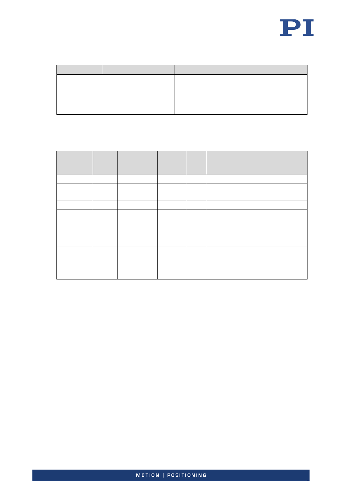
User Manual
Command
Description
Notes
WGO
Set Wave Generator
Triggers recording
0x16000100
3
System
1
INT
Max Number of Data Recorder
0x16000300
1
System
1
INT
Data Recorder Chan Number; the
0x16000700
1
Data recorder
8
INT
DRC Data Source
E727T0005, valid for E-727
BRO, 2018-03-23
WGR Start Recording
For detailed command descriptions see the GCS commands manual PZ281E. For the identifiers of
the items which can be addressed with the commands see "Axes, Channels, Functional Elements"
(p. 22).
Start/Stop Mode
Triggers recording
Synchronous to Wave
Generator
Parameter
ID
0x16000000 1 System 1 INT Data Recorder Table Rate
0x16000200 3 System 1 INT Data Recorder Max Points
0x16000701 1 Data recorder
See "Parameters" (p. 179) for more information regarding the controller parameters and their
handling.
CCL for
Write
Access
Item Type
Concerned
table
table
External Triggering/Signaling
Max. No.
of
Items
8 INT DRC Record Option
Data
Type
Parameter
Description
Channels
available data recorder points are
allocated in equal shares to the
number of tables given by this
parameter
The digital I/O lines of theE-727 are available on the Digital I/O socket, see p. 220 for the lines and
pinout.
Using Digital Input
The values of all digital input lines can be recorded, see the DRC command for details.
The IN1 to IN4 input lines can be used to start data recording, see the DRT command for details.
The IN1 and IN2 input lines can be used in conjunction with the WGO command to trigger the
wave generator output (IN1 and IN2) and to stop it (IN2). See "Wave Generator Started by Trigger
Input" (p. 104) for an example.
Physik Instrumente (PI) GmbH & Co. KG, Auf der Roemerstrasse 1, 76228 Karlsruhe, Germany Page 67 / 228
Phone +49 721 4846-0, Fax +49 721 4846-1019, Email [email protected], www.pi.ws
Page 68

User Manual
E727T0005, valid for E-727
BRO, 2018-03-23
Configuring Trigger Output
The values of the digital output lines OUT1 to OUT3 can be recorded, see the DRC command for
details.
You can program the digital output lines OUT1 to OUT3 to trigger other devices using the CTO
command.
The general format of the CTO command is as follows, i.e. all trigger-related settings for a digital
output line can normally be made with one command line (the number of arguments following a
command mnemonic is limited to 32):
CTO {<TrigOutID> <CTOPam> <Value>}
The following trigger modes are supported by the E-727:
0 = Position Distance; a trigger pulse is written whenever the axis has covered a given
distance. Optionally, values for StartThreshold and StopThreshold can be defined to
enable the trigger output for a limited position range and a certain direction of motion
only (negative or positive). When StartThreshold and StopThreshold are set to the
same value, they will not be used. See "Example—"Position Distance" Trigger Mode"
(p. 70).
2 = OnTarget; the on-target status of the axis is written to the trigger output line (this
status can also be read with the ONT? command). See "Example—"On Target" Trigger
Mode" (p. 74).
3 = MinMaxThreshold; values for MinThreshold and MaxThreshold must be defined.
When the axis position is inside the band specified by the MinThreshold and
MaxThreshold values, the trigger output line is set high, otherwise it is set low. See
"Example—"MinMax Threshold" Trigger Mode" (p. 75).
4 = Generator Level Trigger; the trigger line action must be defined with TWS. The
trigger output will be synchronized with the wave generator output. The length of a
single trigger pulse is the same as the duration of one servo cycle. If the signal level is
set to HIGH with TWS for consecutive points of a wave table, the signal level therefore
does not change back to LOW between the points. See "Example—"Generator Level
Trigger" Mode" (p. 76).
9 = Generator Pulse Trigger; the trigger line action must be defined with TWS. The
trigger output will be synchronized with the wave generator output. The length of a
single trigger pulse is shorter than the servo cycle duration. If the signal level is set to
HIGH with TWS for consecutive points of a wave table, the signal level therefore
changes back to LOW after each point. See "Example—"Generator Pulse Trigger"
Mode" (p. 77).
14 = TriggerOutAND; the digital output line <TrigOutID> outputs the signal states of the
output lines selected with TriggerOutMask (<CTOPam> ID 16). The states of the
selected lines are combined via AND bit operation. See "Examples—"TriggerOutAND"
and "TriggerOutOR" Modes" (p. 78).
15= TriggerOutOR; the digital output line <TrigOutID> outputs the signal states of the
output lines selected with TriggerOutMask (<CTOPam> ID 16). The states of the
selected lines are combined via OR bit operation. See "Examples—"TriggerOutAND"
and "TriggerOutOR" Modes" (p. 78).
Physik Instrumente (PI) GmbH & Co. KG, Auf der Roemerstrasse 1, 76228 Karlsruhe, Germany Page 68 / 228
Phone +49 721 4846-0, Fax +49 721 4846-1019, Email [email protected], www.pi.ws
Page 69
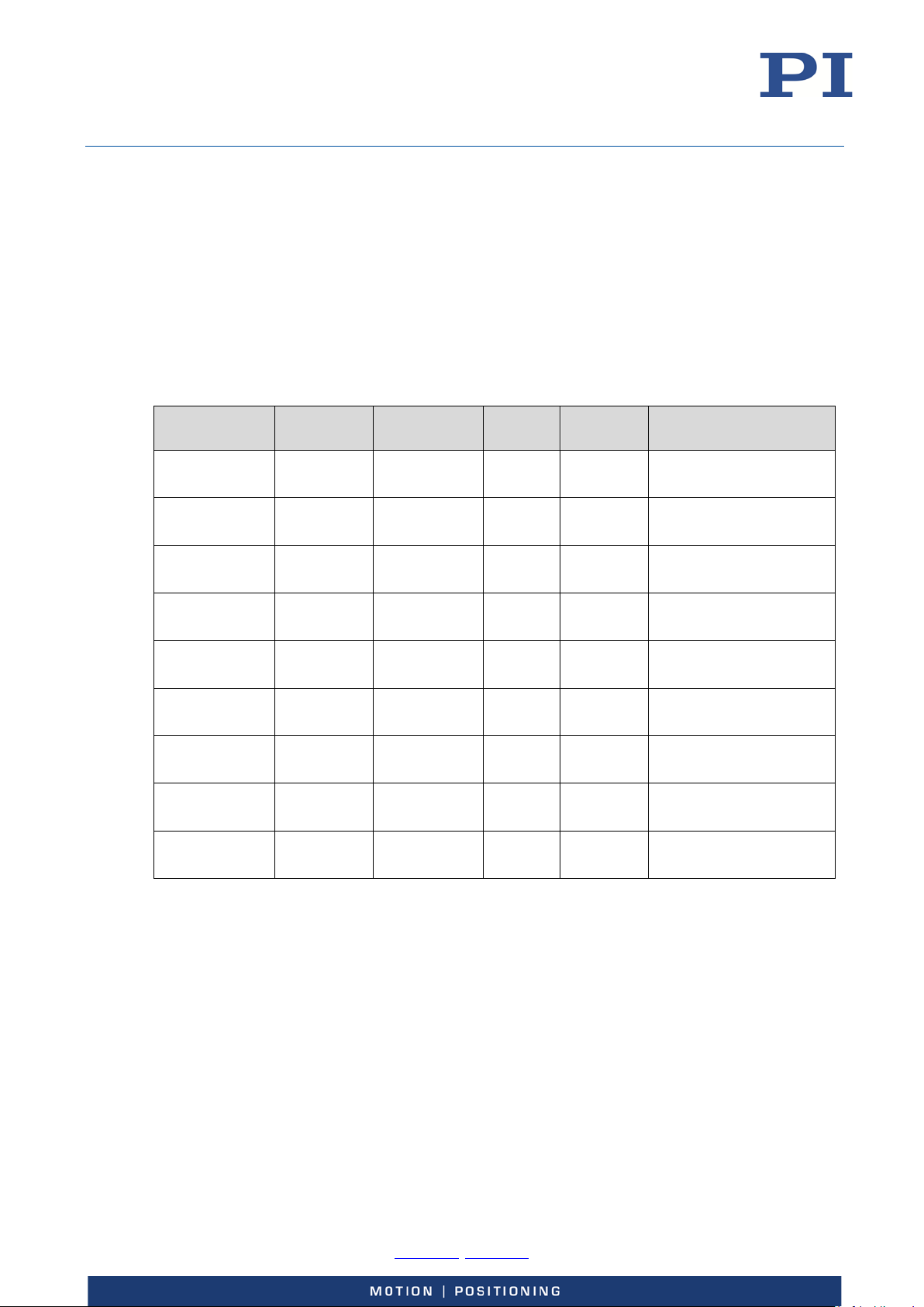
User Manual
0x18000202
1
Digital Output
3
INT
CTO Axis
0x18000206
1
Digital Output
3
FLOAT
CTO Max.Threshold
0x18000209
1
Digital Output
3
FLOAT
CTO Stop Threshold
E727T0005, valid for E-727
BRO, 2018-03-23
To select the mode, set <CTOPam> = 3 and <Value> to the code of the mode; default selection is
On Target (2).
Furthermore, it is possible to select the signal polarity for the digital output line (active high /
active low). See "Example—Polarity Setting" (p. 77).
CTO changes the values of the parameters listed below in volatile memory. The current values in
volatile memory can be read with the CTO? command. You can also change these parameters
using SPA (volatile memory) or SEP (non-volatile memory). Furthermore, you can use WPA to copy
the current values from volatile memory to non-volatile memory, where they become the poweron defaults. When using SPA, SEP or WPA, it is necessary to switch to command level 1 with CCL to
have write access to the parameters. To read the parameter values, you can also query with the
SPA? or SEP? commands.
Parameter ID Command
Level
0x18000201 1 Digital Output
0x18000203 1 Digital Output
0x18000205 1 Digital Output
0x18000207 1 Digital Output
0x18000208 1 Digital Output
0x18000210 1 Digital Output
Item Type
Concerned
Line
Line
Line
Line
Line
Line
Line
Line
Line
Max. No.
of Items
3 FLOAT CTO Trigger Step
3 INT CTO Trigger Mode
3 FLOAT CTO Min.Threshold
3 INT CTO Polarity
3 FLOAT CTO Start Threshold
3 INT CTO Trigger Out Mask
Data Type Parameter Description
(<CTOPam> = 1)
(<CTOPam> = 2)
(<CTOPam> = 3)
(<CTOPam> = 5)
(<CTOPam> = 6)
(<CTOPam> = 7)
(<CTOPam> = 8)
(<CTOPam> = 9)
(<CTOPam> = 16)
Physik Instrumente (PI) GmbH & Co. KG, Auf der Roemerstrasse 1, 76228 Karlsruhe, Germany Page 69 / 228
Phone +49 721 4846-0, Fax +49 721 4846-1019, Email [email protected], www.pi.ws
The following examples can be reproduced using the command entry facilities of PIMikroMove or
PI Terminal.
Page 70
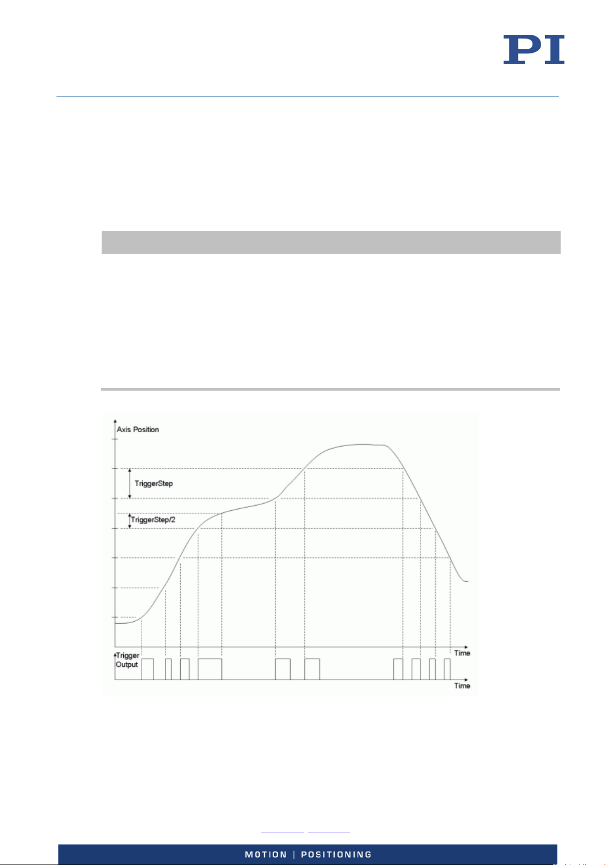
User Manual
During the trigger output in “Position Distance” mode, the E-727 generates a signal which changes
the time interval
E727T0005, valid for E-727
BRO, 2018-03-23
Example—"Position Distance" Trigger Mode
The "Position Distance" trigger mode is designed for scanning applications. A trigger pulse is
written whenever the axis has covered the distance set with CTO (<TriggerStep>). The time interval
of the trigger pulses depends on the position distance set with <TriggerStep> and on the current
velocity of the axis.
The unit of <TriggerStep> is µm or µrad.
INFORMATION
its level each time the axis has covered half the TriggerStep distance.
Example:
If TriggerStep is 100 nm, a rising edge of the trigger signal (low -> high) will be followed by a falling
edge (high -> low) when the axis has covered a distance of 50 nm. The next rising edge follows
when the axis has covered another distance of 50 nm, and so on. This means that
of the trigger pulses will vary with the axis velocity; see also the figure below.
The edges of the trigger signal do not only depend on the current position of the axis, but also on
the direction of motion. Inverting the direction of motion will also invert the signal edges; see also
the figure below.
Figure 17: Position Distance" Trigger Mode
Physik Instrumente (PI) GmbH & Co. KG, Auf der Roemerstrasse 1, 76228 Karlsruhe, Germany Page 70 / 228
Phone +49 721 4846-0, Fax +49 721 4846-1019, Email [email protected], www.pi.ws
Page 71
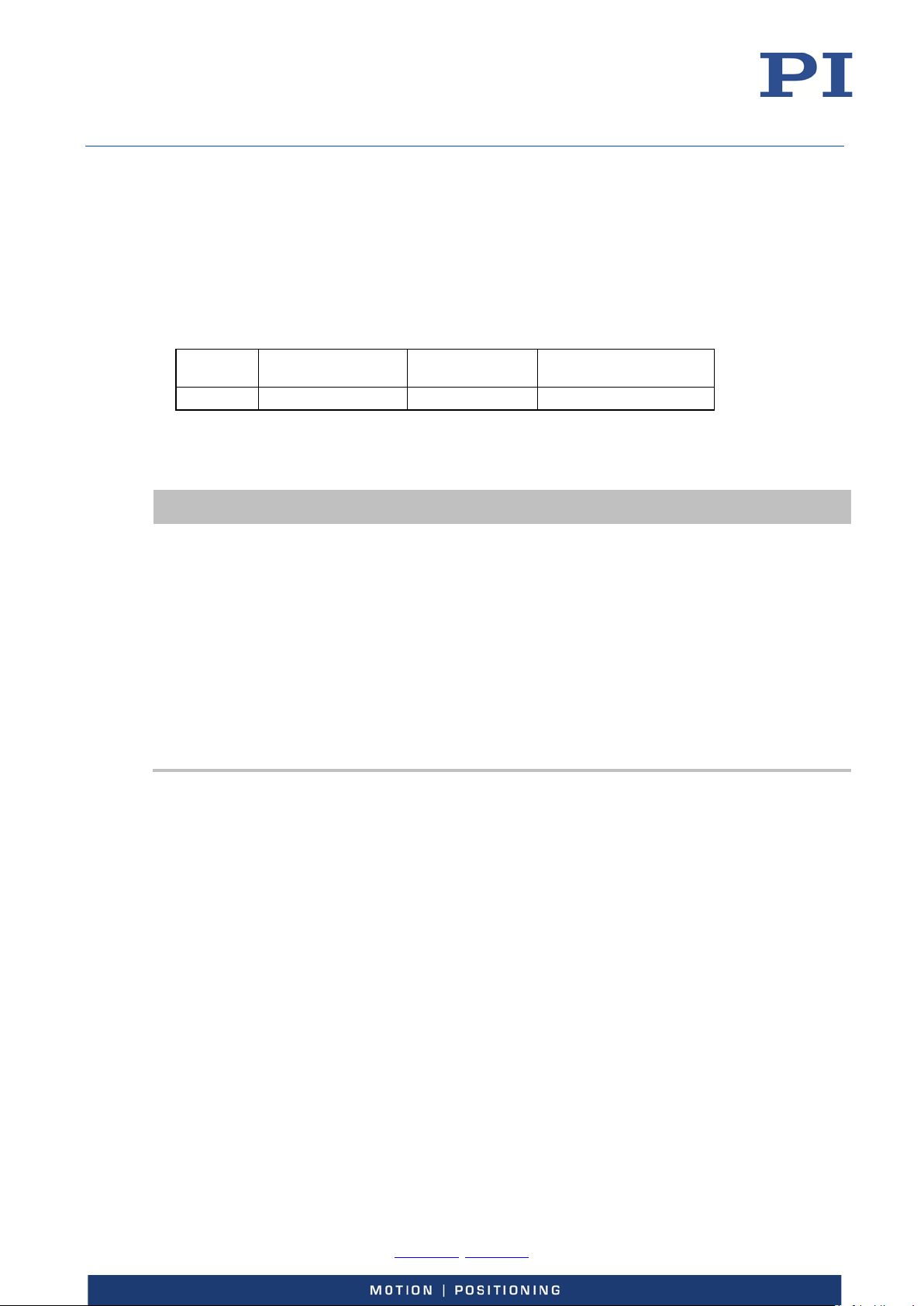
User Manual
Axis
Stepsize
Possible values for TriggerStep depend on the axis velocity.
E727T0005, valid for E-727
BRO, 2018-03-23
The following parameters must be set for the digital output line which is to be used for trigger
output (<TrigOutID>):
Axis (<CTOPam> = 2)
TriggerMode (<CTOPam> = 3)
TriggerStep (<CTOPam> = 1)
General notation of the CTO command for this mode (in fact, the command arguments can be
divided in three "portions", each starting with the <TrigOutID> declaration):
Command
mnemonic
CTO <TrigOutID> 2
Instead of using the CTO command, you can also set the values of the corresponding parameters
with SPA or SEP, see “Configuring Trigger Output” (p. 68) for a parameter list.
INFORMATION
Axis selection
Trigger mode
selection
<TrigOutID> 3 0 <TrigOutID> 1
Step size setting
With high velocities, the minimum TriggerStep value is limited as follows:
TriggerStep > 4 * velocity * Servo Update Time
Servo Update Time is given in seconds by parameter 0x0E000200
Examples (the Servo Update Time of the E-727 is 50 µs):
o With a velocity of 1000 µm/s, the minimum TriggerStep value is 200 nm.
o With a TriggerStep value of 100 nm, the maximum velocity is 500 µm/s.
With very small velocities, the minimum TriggerStep value is limited by the noise of the
position sensor. For reliable triggering, the TriggerStep setting has to be at least 5 times larger
than the 6-sigma level of the sensor noise. The sensor noise level can be reduced by digital
filtering of the signal (p. 27). To detect the noise, you can record, for example, the position
error of the axis using the data recorder.
Example: A pulse on the digital output line 1 is to be generated whenever axis 1 of the stage has
covered a distance of 0.1 µm. Send:
CTO 1 2 1 1 3 0 1 1 0.1
Physik Instrumente (PI) GmbH & Co. KG, Auf der Roemerstrasse 1, 76228 Karlsruhe, Germany Page 71 / 228
Phone +49 721 4846-0, Fax +49 721 4846-1019, Email [email protected], www.pi.ws
Page 72
User Manual
The distance between the start position of the axis and the StartThreshold setting has to be at least
E727T0005, valid for E-727
BRO, 2018-03-23
Optionally, start and stop values can be set with CTO (<StartThreshold> and <StopThreshold>) to
enable the trigger output for a limited position range and a certain direction of motion only
(positive or negative). When <StartThreshold> and <StopThreshold> are set to the same value,
they will not be used. Should the motion direction be reversed before the axis position has reached
the stop threshold, trigger pulses will continue to be generated.
The following parameters must then be set for the digital output line which is to be used for trigger
output (<TrigOutID>):
Axis (<CTOPam> = 2)
TriggerMode (<CTOPam> = 3)
TriggerStep (<CTOPam> = 1)
StartThreshold (<CTOPam> = 8)
StopThreshold (<CTOPam> = 9)
General notation of the CTO command for this option (in fact, the command arguments can be
divided in five "portions", each starting with the <TrigOutID> declaration):
Command
mnemonic
CTO <TrigOutID> 2 Axis <TrigOutID> 3 0 <TrigOutID> 1 Stepsize <TrigOutID> 8 Startpos. <TrigOutID> 9 Stoppos.
Axis selection
Trigger mode
selection
Step size setting Start threshold setting Stop threshold setting
INFORMATION
For reliable activation of the trigger output, the axis has to move through the “Trigger ready, not
active” position range, or the motion has to start in this range (see Figure 18 and Figure 19).
For reliable deactivation of the trigger output, the axis has to move through the “Trigger stopped”
position range, or the motion has to end in this range (see Figure 18 and Figure 19).
3 times larger than the noise of the axis position (peak-to-peak value), as well as the distance
between the end position of the axis and the StopThreshold setting.
See the examples 2 and 3 below for details.
Physik Instrumente (PI) GmbH & Co. KG, Auf der Roemerstrasse 1, 76228 Karlsruhe, Germany Page 72 / 228
Phone +49 721 4846-0, Fax +49 721 4846-1019, Email [email protected], www.pi.ws
Page 73
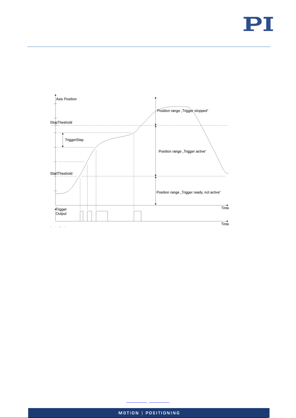
User Manual
E727T0005, valid for E-727
BRO, 2018-03-23
Example 2: A pulse on the digital output line 1 is to be generated whenever axis 1 of the stage has
covered a distance of 0.1 µm, as long as axis 1 moves in positive direction in the range of 0.2 µm to
0.55 µm (start threshold < stop threshold). For reliable activation and deactivation of the trigger
output, the axis motion should start at 0.15 µm and end at 0.6 µm. Send:
CTO 1 2 1 1 3 0 1 1 0.1 1 8 0.2 1 9 0.55
Figure 18: "Position Distance" Trigger Mode with threshold settings for positive direction of motion
Physik Instrumente (PI) GmbH & Co. KG, Auf der Roemerstrasse 1, 76228 Karlsruhe, Germany Page 73 / 228
Phone +49 721 4846-0, Fax +49 721 4846-1019, Email [email protected], www.pi.ws
Page 74
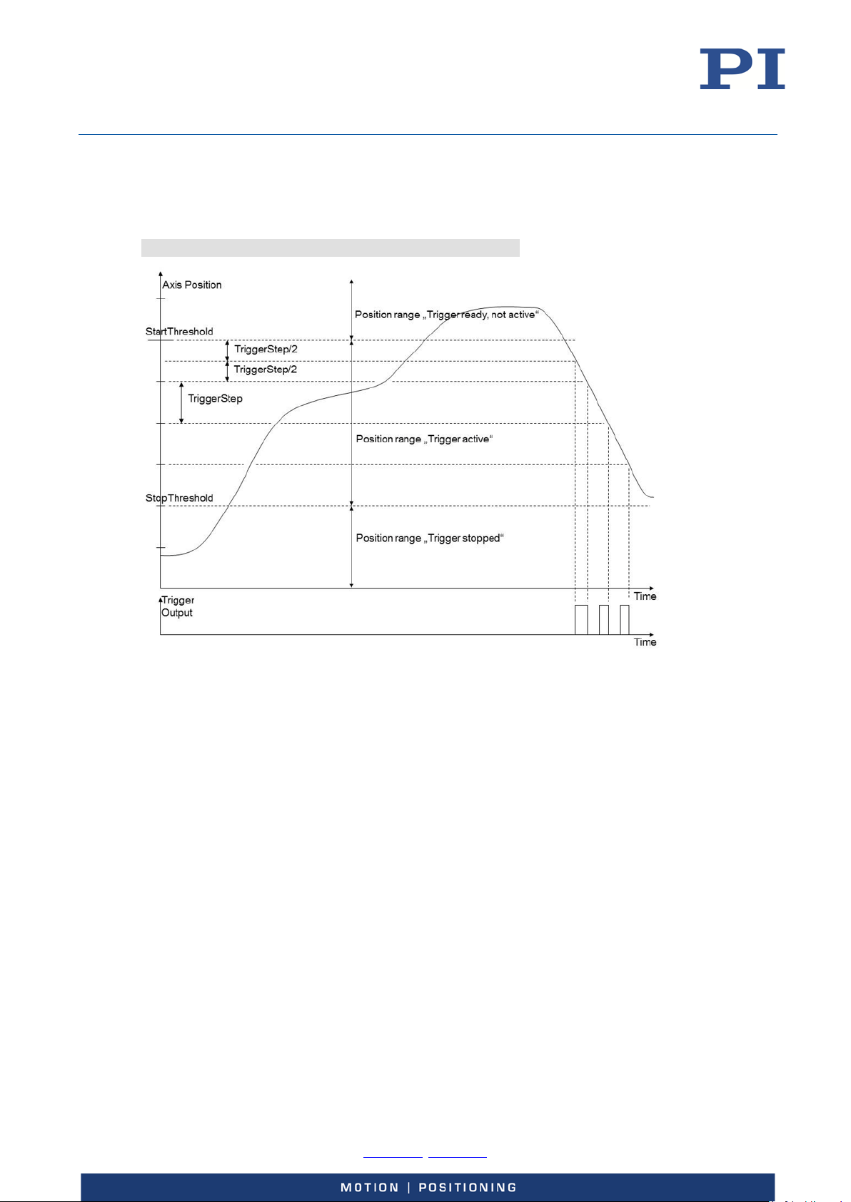
User Manual
E727T0005, valid for E-727
BRO, 2018-03-23
Example 3: A pulse on the digital output line 1 is to be generated whenever axis 1 of the stage has
covered a distance of 0.1 µm, as long as axis 1 moves in negative direction in the range of 0.55 µm
to 0.2 µm (start threshold > stop threshold). For reliable activation and deactivation of the trigger
output, the axis motion should start at 0.6 µm and end at 0.15 µm. Send:
CTO 1 2 1 1 3 0 1 1 0.1 1 8 0.55 1 9 0.2
Figure 19: "Position Distance" Trigger Mode with threshold settings for negative direction of motion; here,
the trigger output is not yet disabled reliably at the end of the curve
Example—"On Target" Trigger Mode
With the "On Target" trigger mode, the on-target status of the selected axis is written to the
selected trigger line. It is the same on-target status flag which can also be read by the ONT?
command. The on-target status is influenced by two parameters: settling window (On Target
Tolerance, ID 0x07000900) and settling time (Settling Time, ID 0x07000901). The on-target status is
true when the current position is inside the settling window and stays there for at least the settling
time. The settling window is centered around the target position.
The following parameters must be set for the digital output line which is to be used for trigger
output (<TrigOutID>):
Axis (<CTOPam> = 2)
TriggerMode (<CTOPam> = 3)
General notation of the CTO command for this mode (in fact, the command arguments can be
divided in two "portions", each starting with the <TrigOutID> declaration):
Physik Instrumente (PI) GmbH & Co. KG, Auf der Roemerstrasse 1, 76228 Karlsruhe, Germany Page 74 / 228
Phone +49 721 4846-0, Fax +49 721 4846-1019, Email [email protected], www.pi.ws
Page 75
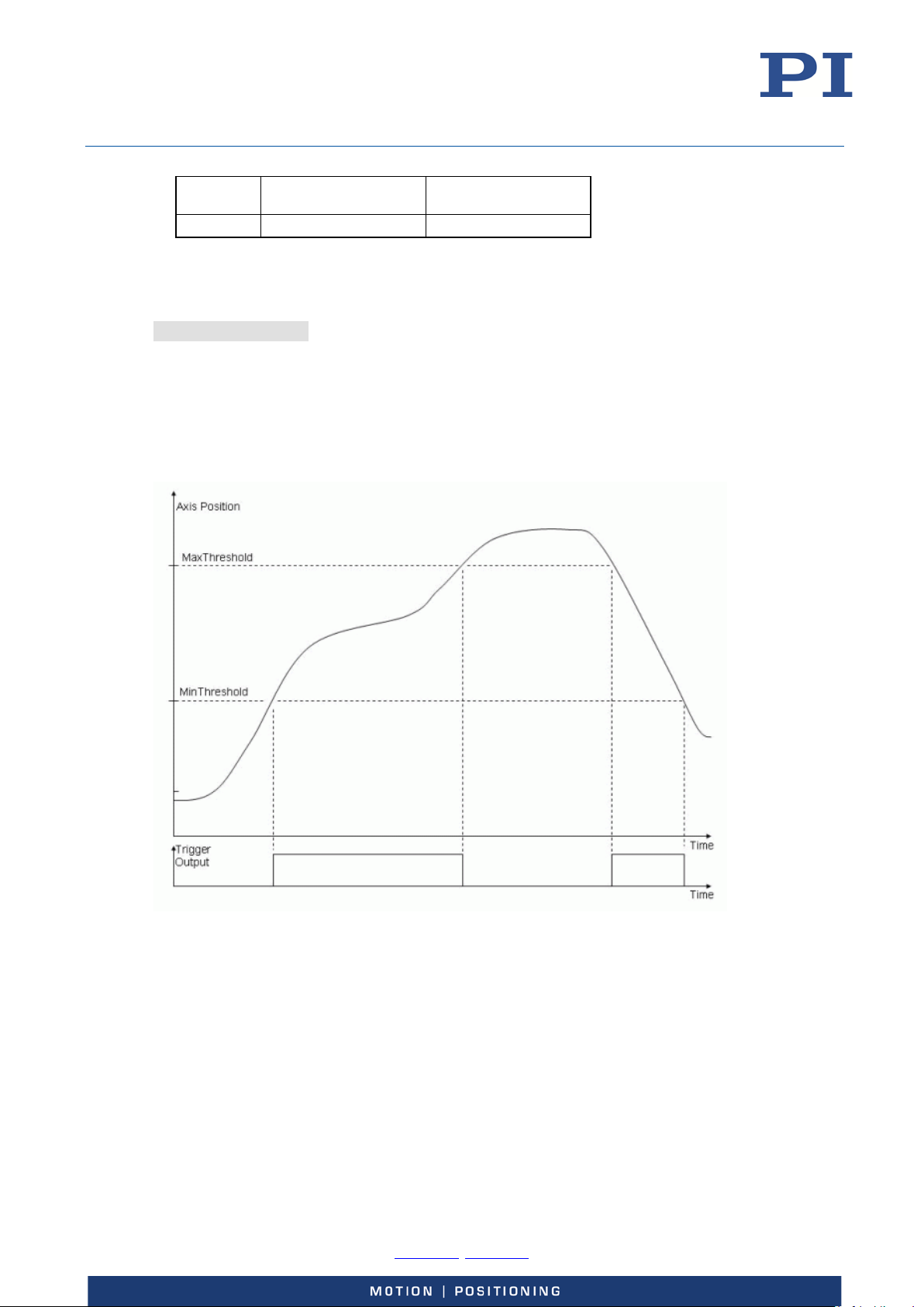
User Manual
E727T0005, valid for E-727
BRO, 2018-03-23
Command
mnemonic
CTO <TrigOutID> 2 Axis <TrigOutID> 3 2
Axis selection Trigger mode selection
Instead of using the CTO command, you can also set the values of the corresponding parameters
with SPA or SEP, see “Configuring Trigger Output” (p. 68) for a parameter list.
Example: The On-Target status flag of axis 1 is to be written to the digital output line 1. Send:
CTO 1 2 1 1 3 2
Example—"MinMax Threshold" Trigger Mode
With the "MinMax Threshold" trigger mode, a band is specified with MinThreshold and
MaxThreshold (<CTOPam> IDs 5 and 6). When the axis position is inside the specified band then
the trigger output line is set high, otherwise it is set low.
Figure 20: "MinMax Threshold" Trigger Mode
The following parameters must be set for the digital output line which is to be used for trigger
output (<TrigOutID>):
Axis (<CTOPam> = 2)
TriggerMode (<CTOPam> = 3)
MinThreshold (<CTOPam> = 5)
MaxThreshold (<CTOPam> = 6)
Physik Instrumente (PI) GmbH & Co. KG, Auf der Roemerstrasse 1, 76228 Karlsruhe, Germany Page 75 / 228
Phone +49 721 4846-0, Fax +49 721 4846-1019, Email [email protected], www.pi.ws
Page 76
User Manual
on default state is also "low"). It is recommended
E727T0005, valid for E-727
BRO, 2018-03-23
General notation of the CTO command for this mode (in fact, the command arguments can be
divided in four "portions", each starting with the <TrigOutID> declaration):
Command
mnemonic
CTO <TrigOutID> 2 Axis <TrigOutID> 3 3 <TrigOutID> 5 min.pos. <TrigOutID> 6 max.pos.
Instead of using the CTO command, you can also set the values of the corresponding parameters
with SPA or SEP, see “Configuring Trigger Output” (p. 68) for a parameter list.
Example: The digital output line 1 is to be set high whenever the axis position of axis 1 is higher
than 0.3 µm and lower than 0.6 µm. Send:
CTO 1 2 1 1 3 3 1 5 0.3 1 6 0.6
Example—"Generator Level Trigger" Mode
With the "Generator Level Trigger" mode, the trigger output will be synchronized with the wave
generator output, and CTO must be used in combination with TWS.
Axis selection
Trigger mode
selection
Min threshold setting Max threshold setting
The length of a single trigger pulse is the same as the duration of one servo cycle. If the signal level
is set to HIGH with TWS for consecutive points of a wave table, the signal level therefore does not
change back to LOW between the points.
The following parameter must be set for the digital output line which is to be used for trigger
output (<TrigOutID>):
TriggerMode (<CTOPam> = 3)
General notation of the CTO command for this mode:
Command mnemonic Trigger mode selection
CTO <TrigOutID> 3 4
Instead of using the CTO command, you can also set the value of the corresponding parameter
with SPA or SEP, see “Configuring Trigger Output” (p. 68) for a parameter list.
Example: Generate trigger pulses synchronized with the wave generator in Generator Level Trigger
mode.
Command String to Send Action Performed
WAV 2 X SIN_P 2000 20 10 2000 0 1000
TWC
TWS 1 500 1 1 1500 1 1 1900 1 1 2000 1
CTO 1 3 4
Define a sine waveform for Wave Table 2, the segment
length and hence the number of points in the wave table is
2000
Clears all output trigger settings related to the wave
generator by switching the signal state for all points to "low"
(the powerto use TWC before new trigger actions are defined.
Set trigger actions for the digital output line OUT1 (identifier
is 1): at the waveform points 500, 1500, 1900 and 2000 it is
set high; at all other points the state of the line is low (due to
the TWC usage).
The digital output line OUT1 is set to "Generator Level
Trigger" mode.
Physik Instrumente (PI) GmbH & Co. KG, Auf der Roemerstrasse 1, 76228 Karlsruhe, Germany Page 76 / 228
Phone +49 721 4846-0, Fax +49 721 4846-1019, Email [email protected], www.pi.ws
Page 77
User Manual
Start output of Wave Generator 1 immediately (synchronized
pol.code
E727T0005, valid for E-727
BRO, 2018-03-23
Command String to Send Action Performed
WSL 1 2 Connect Wave Generator 1 (Axis 1) to Wave Table 2
WGO 1 1
WGO 1 0
Example—"Generator Pulse Trigger" Mode
With the "Generator Pulse Trigger" mode, the trigger output will be synchronized with the wave
generator output, and CTO must be used in combination with TWS.
The length of a single trigger pulse is shorter than the servo cycle duration. If the signal level is set
to HIGH with TWS for consecutive points of a wave table, the signal level therefore changes back to
LOW after each point. This way, the trigger output can be used, for example, to count the
waveform points that are output by the wave generator.
by servo cycle). Now the trigger output action will take place
as specified.
Stop output of Wave Generator 1 and hence also the trigger
output.
The following parameter must be set for the digital output line which is to be used for trigger
output (<TrigOutID>):
TriggerMode (<CTOPam> = 3)
General notation of the CTO command for this mode:
Command mnemonic Trigger mode selection
CTO <TrigOutID> 3 9
Instead of using the CTO command, you can also set the value of the corresponding parameter
with SPA or SEP, see “Configuring Trigger Output” (p. 68) for a parameter list.
Example—Polarity Setting
It is possible to select the signal polarity (active high = 1, default / active low = 0) for the digital
output line which is to be used for trigger output.
The following parameter must be set for the digital output line (<TrigOutID>):
Polarity (<CTOPam> = 7)
General notation of the CTO command for polarity selection:
Command mnemonic Trigger mode selection
CTO <TrigOutID> 7
Instead of using the CTO command, you can also set the value of the corresponding parameter
with SPA or SEP, see “Configuring Trigger Output” (p. 68) for a parameter list.
Example: The signal polarity for the digital output line 1 is to be set to "active low". Send:
CTO 1 7 0
Physik Instrumente (PI) GmbH & Co. KG, Auf der Roemerstrasse 1, 76228 Karlsruhe, Germany Page 77 / 228
Phone +49 721 4846-0, Fax +49 721 4846-1019, Email [email protected], www.pi.ws
Page 78
User Manual
Digital Out 1
0
0x1
1
Digital Out 3
2
0x4
4
CTO
<TrigOutID> 3 15
<TrigOutID> 16 TriggerOutMask
E727T0005, valid for E-727
BRO, 2018-03-23
Examples—"TriggerOutAND" and "TriggerOutOR" Modes
With the "TriggerOutAND" and "TriggerOutOR" trigger modes, the signal states of multiple digital
output lines are combined by a logical operation, and the result is written to another trigger line. A
bit-mapped mask selects the digital output lines whose signal states are to be logically combined.
The mask can be specified in hex or decimal format.
Bit-mapped mask values of the digital output lines:
Digital output line Bit Value in hex format Value in decimal format
Digital Out 2 1 0x2 2
The following parameters must be set for the digital output line which is to be used for trigger
output (<TrigOutID>):
TriggerMode (<CTOPam> = 3)
TriggerOutMask (<CTOPam> = 16)
General notation of the CTO command for the TriggerOutAND mode:
Command mnemonic Trigger mode selection Axis selection
CTO <TrigOutID> 3 14 <TrigOutID> 16 TriggerOutMask
General notation of the CTO command for the TriggerOutOR mode:
Command mnemonic Trigger mode selection Axis selection
Instead of using the CTO command, you can also set the values of the corresponding parameters
with SPA or SEP, see “Configuring Trigger Output” (p. 68) for a parameter list.
Example 1: The signal states of digital output lines 1 and 3 are to be combined by a logical AND
operation. The result is to be written to the digital output line 2. The mask for selection of the
digital output lines to be combined is specified in hex format. Send:
CTO 2 3 14 2 16 0x5
Example 2: The signal states of digital output lines 2 and 3 are to be combined by a logical OR
operation. The result is to be written to the digital output line 1. The mask for selection of the
digital output lines to be combined is specified in decimal format. Send:
CTO 1 3 15 1 16 6
Physik Instrumente (PI) GmbH & Co. KG, Auf der Roemerstrasse 1, 76228 Karlsruhe, Germany Page 78 / 228
Phone +49 721 4846-0, Fax +49 721 4846-1019, Email [email protected], www.pi.ws
Page 79
User Manual
E727T0005, valid for E-727
BRO, 2018-03-23
Using the Analog Input
How to Work with the Analog Input - Overview
With models E-727.xxxA and .xxxAx, four analog inputs are available on the Analog I/O socket
(p. 221). In the firmware of the E-727, the analog input lines are represented by the input signal
channels 4 to 7.
The voltage range of an analog input (±5 V or ±10 V) can be configured via the value of the
corresponding Sensor Range Factor parameter (ID 0x02000100).
You can use an analog input line as follows:
Connect an external sensor
Connect a source for control value generation
INFORMATION
E-727.3SDA, .3SDAx, .3RDA and .3RDAx models only:
Input signal channel 4 can also be used for sensor input on the socket for piezo stages (p. 219).
The corresponding configuration is done via the value of the Sensor Range Factor parameter (ID
0x02000100) as follows:
1: Use with a piezoresistive or strain gauge sensor (input via pins 6, 24, 25)
2: Use with a PT1000 temperature sensor (input via pins 1, 20)
For further details, see the description of the input signal channels in „Axes, Channels, Functional
Elements“ (p. 22).
Irrespective of the intended usage, the analog input values must first be scaled to suitable position
values (see "Scaling the Analog Input" (p. 81)). Then, to set the usage of the analog input, it is
furthermore necessary to change certain controller parameters. See "Use as Control Value
Generation Source" (p. 84) or "Use as External Sensor Input" (p. 85) for details. Analog input lines
which are not used should be deactivated to avoid interferences, see "Deactivation of Unused
Analog Input Lines" (p. 86) for details.
Physik Instrumente (PI) GmbH & Co. KG, Auf der Roemerstrasse 1, 76228 Karlsruhe, Germany Page 79 / 228
Phone +49 721 4846-0, Fax +49 721 4846-1019, Email [email protected], www.pi.ws
Page 80
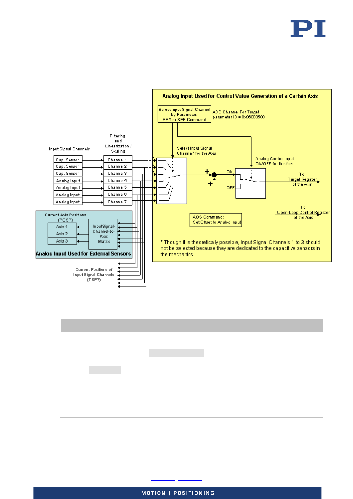
User Manual
Changing the parameter values for configuration of the analog input requires command level 1.
E727T0005, valid for E-727
BRO, 2018-03-23
Figure 21: Overview over the usage of the analog input lines, exemplified by E-727.3CDA
INFORMATION
Switch to command level 1 as follows:
In a terminal program: Send CCL 1 advanced
When prompted to enter a password in any PC software, e.g. in PIMikroMove:
Enter advanced.
If you want to work in the Device Parameter Configuration window of PIMikroMove (for an
example, see p. 52):
Read "Device Parameter Configuration" in the PIMikroMove manual.
Determine, modify and save parameter values with the corresponding buttons and menu
items in the Device Parameter Configuration window of PIMikroMove.
Physik Instrumente (PI) GmbH & Co. KG, Auf der Roemerstrasse 1, 76228 Karlsruhe, Germany Page 80 / 228
Phone +49 721 4846-0, Fax +49 721 4846-1019, Email [email protected], www.pi.ws
Page 81
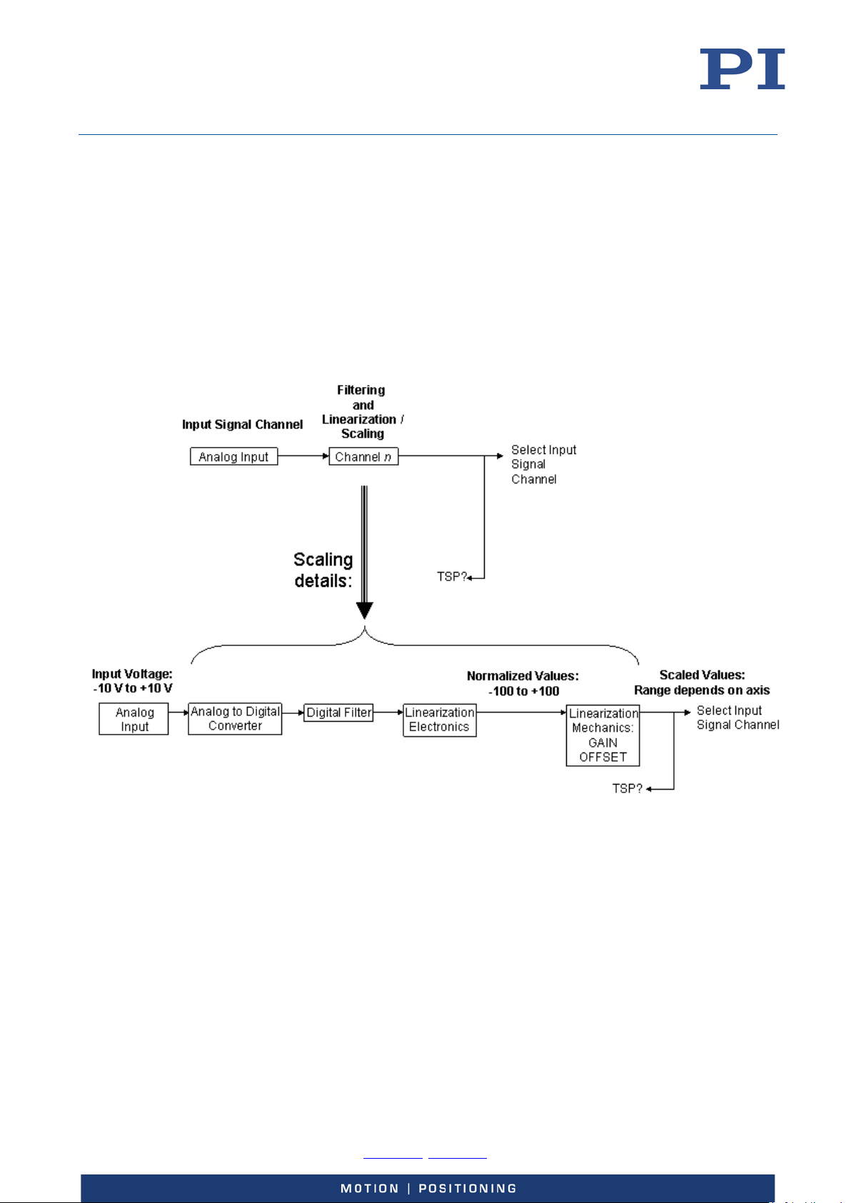
User Manual
E727T0005, valid for E-727
BRO, 2018-03-23
Scaling the Analog Input
Before the analog input line can be used with an external sensor or with a control-signal source,
the input levels must be associated with suitable position values. To do this, adjust the OFFSET
(parameter ID 0x02000200) and the GAIN (parameter ID 0x02000300) of the Mechanics
linearization polynomial according to the travel range of the axis and the input signal range. See
below for details. The TSP? command reports the analog input values after the scaling as position
values in µm.
In addition, the digital filter parameters can be adjusted. See "Digital processing" (p. 27) for details.
How to adjust OFFSET and GAIN to map the analog input voltage to a suitably scaled position value
for a certain axis:
Figure 22: Processing of an analog input signal, detail from the overview figure above
Input Voltage:
The range is -10 to +10 V or -5 to +5V, depending on the value of the Sensor Range Factor
parameter (ID 0x02000100).
Normalized Value:
The polynomial used for electronics linearization (see "Digital processing" for details) converts the
analog input voltage to a number in the range of -100 to +100. The minimum input voltage value
corresponds to -100, and the maximum input voltage corresponds to +100 respectively. If, for
example, an input range of -10 to +10 V is selected, then -10 V correspond to -100, and +10 V
correspond to +100.
Physik Instrumente (PI) GmbH & Co. KG, Auf der Roemerstrasse 1, 76228 Karlsruhe, Germany Page 81 / 228
Phone +49 721 4846-0, Fax +49 721 4846-1019, Email [email protected], www.pi.ws
Page 82

User Manual
E727T0005, valid for E-727
BRO, 2018-03-23
Scaled Value:
The range depends on the axis and can be set by the coefficients of the polynomial used for
Mechanics linearization (see "Digital processing" for details):
ScaledValue = OFFSET + GAIN * NormalizedValue
where
OFFSET corresponds to the Sensor Mech. Correction 1 parameter, ID 0x02000200
GAIN corresponds to the Sensor Mech. Correction 2 parameter, ID 0x02000300
If no linearization is necessary, the other coefficients of the Mechanics linearization polynomial can
be set to zero (parameter IDs 0x02000400, 0x02000500, 0x02000600).
Note that in PIMikroMove, these parameters are available in the Sensor Mechanics 4 to Sensor
Mechanics 7 parameter groups in the Device Parameter Configuration window.
How to calculate the values to set for OFFSET and GAIN:
GAIN = (MaxScaledValue - MinScaledValue) / (MaxNormalizedValue - MinNormalizedValue)
OFFSET = MaxScaledValue - GAIN * MaxNormalizedValue
The values of "MinScaledValue" and "MaxScaledValue" depend on the travel range of the axis with
which the analog input line is to be used:
"MinScaledValue" is given by the TMN? answer (is defined by the Range Limit min parameter, ID =
0x07000000), and "MaxScaledValue" is given by the TMX? answer (is defined by the Range Limit
max parameter, ID = 0x07000001).
The values of "MinNormalizedValue" and "MaxNormalizedValue" depend on the range of the
external signal applied to the analog input line. See the examples below.
For all examples, the following is assumed:
Input signal channel 4 (pins 2 and 9 of Analog I/O) is to be used with axis 1.
Via the Sensor Range Factor parameter, a maximum input range of -10 to +10 V is
selected for input signal channel 4.
Axis 1 has the following travel range:
MinScaledValue = -20 µm
MaxScaledValue = +120 µm
Example 1:
The full range of -10 V to +10 V is to be used (this is recommended for highest resolution).
MinNormalizedValue = -100
MaxNormalizedValue = +100
GAIN = (120 - (-20)) / (100 - (-100)) = 0.7
OFFSET = 120 - 0.7 * 100 = 50
ScaledValue = 50 + 0.7 * NormalizedValue
Physik Instrumente (PI) GmbH & Co. KG, Auf der Roemerstrasse 1, 76228 Karlsruhe, Germany Page 82 / 228
Phone +49 721 4846-0, Fax +49 721 4846-1019, Email [email protected], www.pi.ws
Page 83
User Manual
E727T0005, valid for E-727
BRO, 2018-03-23
So you have to send
SPA 4 0x02000200 50
SPA 4 0x02000300 0.7
to adjust the GAIN and OFFSET parameters for input signal channel 4.
Example 2:
Only positive input voltages are to be used, i.e. the range is 0 V to +10 V.
MinNormalizedValue = 0
MaxNormalizedValue = +100
GAIN = (120 - (-20)) / (100 - 0) = 1.4
OFFSET = 120 - 1.4 * 100 = -20
ScaledValue = -20 + 1.4 * NormalizedValue
Send:
SPA 4 0x02000200 -20
SPA 4 0x02000300 1.4
Example 3:
Positions with positive sign shall correspond to positive input voltages, and positions with negative
sign shall correspond to negative input voltages.
The positive input voltage ranges to +10 V.
Then, the following is valid provided that the absolute value of the negative positions will never be
greater than the positive positions.
MinNormalizedValue = 0
MaxNormalizedValue = +100
GAIN = (120 - 0)) / (100 - 0) = 1.2
OFFSET = 120 - 1.2 * 100 = 0
ScaledValue = 1.2 * NormalizedValue
Send:
SPA 4 0x02000200 0
SPA 4 0x02000300 1.2
Note that these OFFSET and GAIN values would also be valid if axis 1 had a travel range of 0 to
120 µm and if there were only positive input voltages to +10 V.
Physik Instrumente (PI) GmbH & Co. KG, Auf der Roemerstrasse 1, 76228 Karlsruhe, Germany Page 83 / 228
Phone +49 721 4846-0, Fax +49 721 4846-1019, Email [email protected], www.pi.ws
Page 84

User Manual
E727T0005, valid for E-727
BRO, 2018-03-23
Example 4:
The same conditions as in example 3 are valid, but the positive input voltages range to +5 V.
MinNormalizedValue = 0
MaxNormalizedValue = +50
GAIN = (120 - 0)) / (50 - 0) = 2.4
OFFSET = 120 - 2.4 * 50 = 0
ScaledValue = 2.4 * NormalizedValue
Send:
SPA 4 0x02000200 0
SPA 4 0x02000300 2.4
Use as Control Value Generation Source
To enable the analog control input for an axis, an input signal channel must be connected to that
axis. This is done with the ADC Channel For Target parameter (ID 0x06000500). If the connection
of axis and input signal channel is saved as the power-on default, the axis can be commanded via
analog input immediately after controller start-up, and no host PC is required. Example: With an E-
727.3CDA, the input signal channel 4 (pins 2 and 9 of Analog I/O) is to be used to command axis 1.
Send:
SPA 1 0x06000500 4
to enable the connection in volatile memory. Note that in PIMikroMove, this parameter is available
in the Target Manipulation 1 parameter group in the Device Parameter Configuration window.
When the analog control input is enabled for an axis, then it overwrites the values of all other
control sources for that axis except those from the AutoZero procedure. The AutoZero procedure
has the highest priority, i.e. it will overwrite the control values given by all other sources. When the
analog control input is enabled, it will be disabled automatically at the start of the AutoZero
procedure and reenabled again when AutoZero is finished. See "Control Value Generation" (p. 30)
for more information.
An offset value can be added to the analog input scaled value for an axis using the AOS command.
When no input signal channel is connected to an axis (i.e. the value of the ADC Channel For Target
parameter is 0), the analog control input is disabled for that axis (including the offset set with
AOS).
When the analog input is used as control source and the axis motion is stopped with STP or #24,
the behaviour depends on the value of the Disconnect Analog Target Input When Stopping
parameter (ID 0x0E001E00): 1 = the analog input channel is disconnected from the axis; 0 = the
analog input channel remains connected to the axis. If the analog input channel is disconnected
from the axis: To recommence commanding the axis via the analog input, the corresponding input
signal channel must be reconnected to the axis. See the description above.
When the analog input is being used as control source and the servo mode is switched off, the axis
motion will continue in open-loop mode.
Physik Instrumente (PI) GmbH & Co. KG, Auf der Roemerstrasse 1, 76228 Karlsruhe, Germany Page 84 / 228
Phone +49 721 4846-0, Fax +49 721 4846-1019, Email [email protected], www.pi.ws
Page 85
User Manual
E727T0005, valid for E-727
BRO, 2018-03-23
INFORMATION
The analog input values must be scaled to suitable position values. See "Scaling the Analog Input"
(p. 81) for more information.
Make sure that the analog input line which is used to control an axis is not used as external sensor
for the same axis. This means that in the input matrix, the coefficient of the appropriate analog
input line must be set to zero for that axis.
The coefficients of the analog input lines are represented by the values of the Position From
Sensor 4 to Position From Sensor 7 parameters (IDs 0x07000503 to 0x07000506). In
PIMikroMove, these parameters are available in the Axis Definition parameter groups in the
Device Parameter Configuration window.
Use as External Sensor Input
To let the sensor on the analog input line participate in the position signal of an axis, set the
corresponding coefficient in the input matrix to 1 for that axis. Example: With an E-727.3CDA, an
external sensor is connected to input signal channel 4 (pins 2 and 9 of Analog I/O). This sensor is to
be used to measure the position of axis 1, i.e. the Position From Sensor 4 parameter (ID
0x07000503) must be set to 1 for axis 1. Send:
SPA 1 0x07000503 1
to change the coefficient in volatile memory. In PIMikroMove, this parameter is available in the
Axis Definition 1 parameter group in the Device Parameter Configuration window.
If only the external sensor on the analog input line is to be used for position measurement of an
axis, the signals of all other sensors must be excluded from the position monitoring of that axis,
especially the signals of the internal sensors integrated in the mechanics. To do this, set the
corresponding coefficients in the input matrix to zero for that axis (with the E-727.3CDA, the
internal sensors are represented by the Position from Sensor 1 to Position from Sensor 3
parameters). Example: To deactivate the first internal sensor for axis 1, send:
SPA 1 0x07000500 0
The position of the axis (i.e. the POS? response) will then be based on the external sensor only, but
it is still possible to read the signals of all sensors using the TSP? command.
INFORMATION
The analog input values must be scaled to suitable position values. See "Scaling the Analog Input"
(p. 81) for more information.
Make sure that internally, the analog input line used to monitor the position of an axis is not
connected to the same axis for control value generation. This means that the value of the ADC
Channel For Target parameter (ID 0x06000500) for an axis must be different from the identifier of
the analog input line which is used as external sensor for that axis. In PIMikroMove, you can check
this in the Target Manipulation parameter groups in the Device Parameter Configuration
window.
Physik Instrumente (PI) GmbH & Co. KG, Auf der Roemerstrasse 1, 76228 Karlsruhe, Germany Page 85 / 228
Phone +49 721 4846-0, Fax +49 721 4846-1019, Email [email protected], www.pi.ws
Page 86
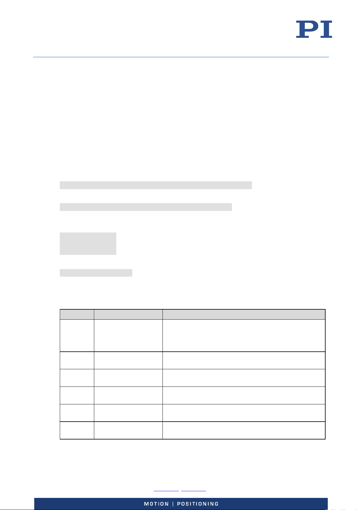
User Manual
Command
Description
Notes
AOS
Set Analog Input Offset
Adds an offset value to the analog input scaled value
AOS?
Get Analog Input Offset
Reads the current value of Analog Target Offset,
SEP
Set Nonvolatile
Can be used to set the power-on default configuration for
SEP?
Get Nonvolatile
Reads the current parameter values from nonvolatile
SPA
Set Temporary Memory
Can be used to set a temporary configuration for analog
E727T0005, valid for E-727
BRO, 2018-03-23
Deactivation of Unused Analog Input Lines
Analog input lines which are not used should be deactivated to avoid interferences. To deactivate
an unused analog input line, the following settings must be done:
Exclude the analog input line from the calculation of axis positions by setting its coefficients for all
axes to zero in the input matrix (Position from Sensor n parameters).
Make sure that the analog input line is not connected to an axis for control value generation. This
means that the value of the ADC Channel For Target parameter, ID 0x06000500, for all axes must
be different from the ID of the analog input line.
Example: The input signal channel 7 (pins 5 and 12 of Analog I/O) of an E-727.3CDA model is to be
deactivated temporarily (i.e. in volatile memory). The input matrix coefficients of that channel
correspond to the Position from Sensor 7 parameters (ID 0x07000506) for axis 1 to axis 3.
Send:
SPA 1 0x07000506 0 2 0x07000506 0 3 0x07000506 0
to exclude the analog input line from the axis position calculation. Then send:
SPA? 1 0x06000500 2 0x06000500 3 0x06000500
to check the RAM settings for the axis control value generation. The response must be different
from 7 for all axes, i.e. if the E-727 replies
1 0x06000500=7
2 0x06000500=3
3 0x06000500=0
then input signal channel 7 is still connected to axis 1, and you have to send
SPA 1 0x06000500 0
to disconnect it.
Analog-Input-Related Commands and Parameters
(Analog Target Offset, ID 0x06000501). This offset is
active as long as the analog input is enabled as control
source for this axis.
parameter ID 0x06000501, from volatile memory
Memory Parameters
analog input usage.
Memory Parameters
Parameters
SPA? Get Temporary
Memory Parameters
Physik Instrumente (PI) GmbH & Co. KG, Auf der Roemerstrasse 1, 76228 Karlsruhe, Germany Page 86 / 228
Phone +49 721 4846-0, Fax +49 721 4846-1019, Email [email protected], www.pi.ws
memory
input usage.
Reads the current parameter values from volatile memory
(RAM)
Page 87
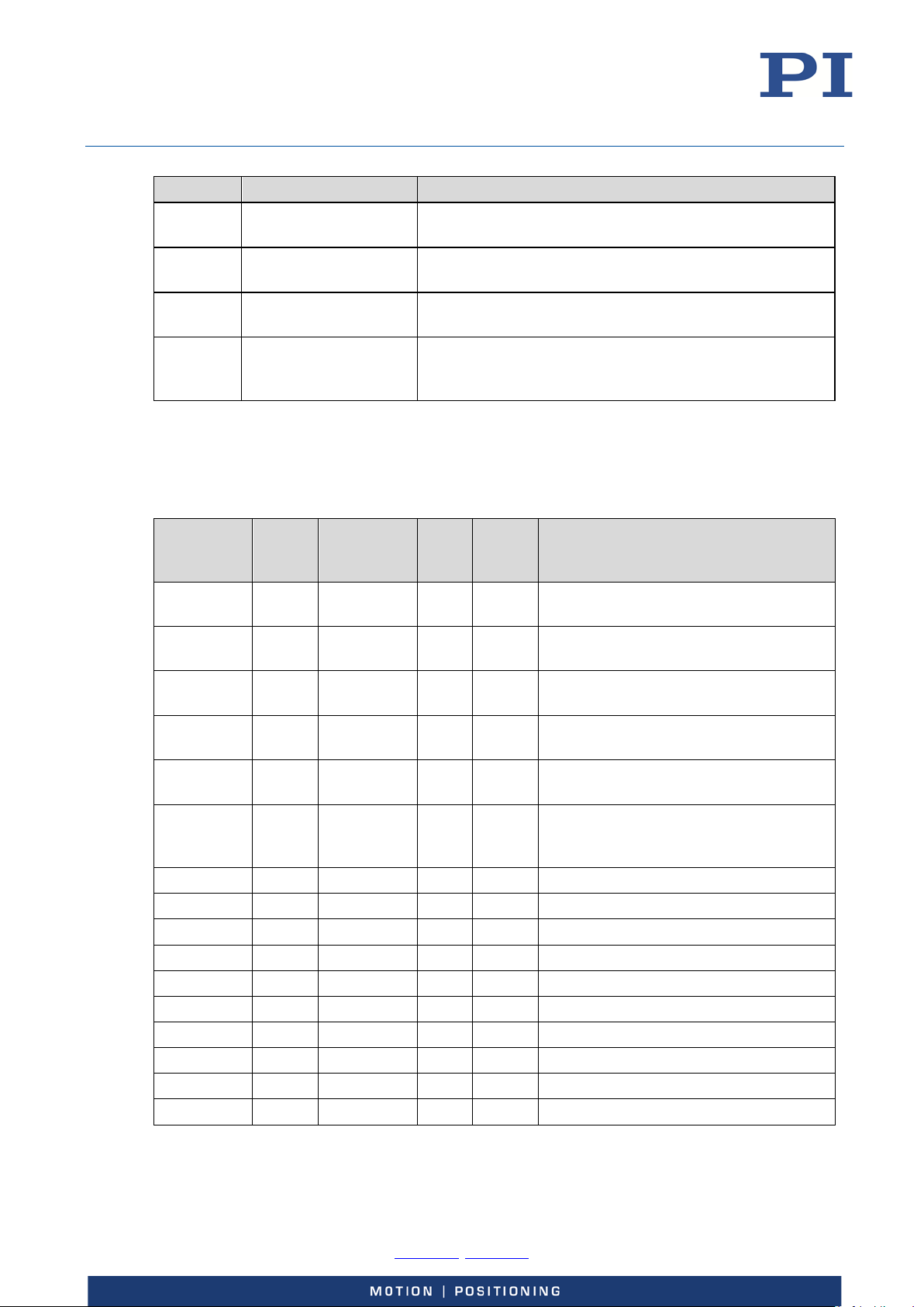
User Manual
Command
Description
Notes
TAD?
Get ADC Value Of Input
Reports the current ADC value of the analog input,
0x05000001
1
Input Signal
7
FLOAT
Digital Filter Bandwidth
0x05000002
1
Input Signal
7
INT
Digital Filter Order
0x07000500
1
Logical Axis
3
FLOAT
Position from Sensor 1
0x07000502
1
Logical Axis
3
FLOAT
Position from Sensor 3
0x07000505
1
Logical Axis
3
FLOAT
Position from Sensor 6
0x0e000b00
3
System
1
INT
Number of input channels
E727T0005, valid for E-727
BRO, 2018-03-23
Signal
TNS? Get Normalized Input
Signal Value
TSP? Get Input Signal
Position Value
WPA Save Parameters To
Nonvolatile Memory
See "How to work with the Analog Input - Overview" (p. 79) for more information. For detailed
command descriptions see the GCS commands manual PZ281E. For the identifiers of the items
which can be addressed with the commands see " Axes, Channels, Functional Elements " (p. 22).
See " Parameters" (p. 179) for more information regarding the controller parameters and their
handling.
Parameter
ID
0x02000200 1 Input Signal
0x02000300 1 Input Signal
0x05000000 1 Input Signal
CCL for
write
access
Item Type
Concerned
Channel
Channel
Channel
dimensionless
Reports the resulting value for the analog input after the
electronics linearization, dimensionless
Reports the resulting value for the analog input after the
mechanics linearization (scaling), the unit is µm
Can be used to save the currently active configuration
(including analog input usage) to nonvolatile memory,
where it becomes the power-on default.
Max.
No. of
Items
7 FLOAT Sensor Mech. Correction 1 (Offset)
7 FLOAT Sensor Mech. Correction 2 (Gain)
7 INT Digital Filter Type
Data
Type
Parameter
Description
Channel
Channel
0x06000500 1 Logical Axis 3 INT ADC Channel for Target; if 0, then the
analog control input is disabled for the
axis
0x06000501 1 Logical Axis 3 FLOAT Analog Target Offset
0x07000501 1 Logical Axis 3 FLOAT Position from Sensor 2
0x07000503 1 Logical Axis 3 FLOAT Position from Sensor 4
0x07000504 1 Logical Axis 3 FLOAT Position from Sensor 5
0x07000506 1 Logical Axis 3 FLOAT Position from Sensor 7
0x0e000b03 3 System 1 INT Number of sensor channels
Physik Instrumente (PI) GmbH & Co. KG, Auf der Roemerstrasse 1, 76228 Karlsruhe, Germany Page 87 / 228
Phone +49 721 4846-0, Fax +49 721 4846-1019, Email [email protected], www.pi.ws
Page 88
User Manual
If the piezo stage(s) delivered with the E-727 do(es) not use the 4th amplifier, parameters Select
E727T0005, valid for E-727
BRO, 2018-03-23
Using the Analog Output
How to Work with the Analog Output - Overview
With models E-727.xxxA and .xxxAx, one analog output is available on pin 8 of the Analog I/O
socket (p. 221). This analog output is accessible in the firmware of the E-727 as output signal
channel 4. Note that the analog output shares output signal channel 4 with the Piezo Ch 4 lines on
the socket for piezo stages (p. 218 or p. 219).
Output signal channel 4 can therefore be configured via parameters Select Output Type (ID
0x0a000003) and Select Output Index (ID 0x0a000004).
Via the value of the Select Output Type parameter (ID 0x0A000003), you can select the purpose for
which the analog output is to be used:
1: Output voltage for a piezo actuator in the stage, output as Piezo Ch 4 on the
socket for piezo stages. The internal control voltage for channel 4 is scaled to be in
the range of -30 to 130 V.
2: Position monitor of an axis, output on pin 8 of the Analog I/O socket. The value of
the Select Output Index parameter (ID 0x0A000004) determines the axis whose
position is to be output. Note that the output has to be scaled, i.e. the axis position
values have to be associated with suitable output levels (= scaled position values). To
do this, set the Position Report Scaling parameter, ID 0x07001005, and the Position
Report Offset parameter, ID 0x07001006 to suitable values for the appropriate axis.
For an example, see p. 89.
5: Control signal for an external amplifier, output on pin 8 of the Analog I/O socket.
The value of the Select Output Index parameter (ID 0x0A000004) determines the
output signal channel whose control value is to be output. The internal control
voltage for channel 4 is already scaled to be in the range of -10 to 10 V. For an
example, see p. 90.
Via the value of the Select Output Index parameter, you can connect the analog output with the
axis or channel whose signal is to be output:
If Select Output Type has the value 1 or 5, the value of Select Output Index gives the
identifier of the output signal channel whose control value is to be used.
If Select Output Type has the value 2, the value of Select Output Index gives the identifier of
the axis whose position is to be output.
INFORMATION
Output Type and Select Output Index are preset so that the position of axis 1 is output on pin 8 of
the Analog I/O socket.
If a total of four piezo actuators are present in the stage(s), output signal channel 4 is configured
for use as output voltage (Select Output Type has value 1, Select Output Index has value 4).
Note that PI will supply E-727 and the piezo stage(s) as a system with appropriate settings.
If you are not sure whether your system can be configured for output of position monitor or
control signal, contact our customer service department (p. 227).
Physik Instrumente (PI) GmbH & Co. KG, Auf der Roemerstrasse 1, 76228 Karlsruhe, Germany Page 88 / 228
Phone +49 721 4846-0, Fax +49 721 4846-1019, Email [email protected], www.pi.ws
Page 89
User Manual
Changing the parameter values for configuration of the analog output requires command level 1.
E727T0005, valid for E-727
BRO, 2018-03-23
INFORMATION
To achieve the highest possible resolution and eliminate potential interference that affects the
cable used:
Filter the analog signal in a suitable way, e.g., before you convert it to a digital format.
Recommended: low-pass filter with max. 100 kHz cut-off frequency (characteristics: single
pole, 6 dB/octave)
INFORMATION
Switch to command level 1 as follows:
In a terminal program: Send CCL 1 advanced
When prompted to enter a password in any PC software, e.g. in PIMikroMove:
Enter advanced.
If you want to work in the Device Parameter Configuration window of PIMikroMove (for an
example, see p. 52):
Read "Device Parameter Configuration" in the PIMikroMove manual.
Determine, modify and save parameter values with the corresponding buttons and menu
items in the Device Parameter Configuration window of PIMikroMove.
For further details, see the description of the output signal channels in „Axes, Channels, Functional
Elements“ (p. 20) and the information in „E-727.xxxA, E-727.xxxAx: Analog I/O“ (p. 221).
Use as Position Monitor
Example: The position of axis 3 is to be monitored via the analog output on pin 8 of the Analog I/O
socket (= output signal channel 4).
1. Select output type 2 = "position monitor of an axis" for the analog output line using the
Select Output Type parameter:
If you work in a terminal program, send the following command to change the
parameter value in volatile memory:
SPA 4 0x0A000003 2
In PIMikroMove, this parameter is available in the DAC 4 parameter group in the Device
Parameter Configuration window.
2. Connect the axis (axis identifier is 3) to the analog output line using the Select Output
Index parameter:
If you work in a terminal program, send the following command to change the
parameter value in volatile memory:
SPA 4 0x0A000004 3
In PIMikroMove, this parameter is also available in the DAC 4 parameter group in the
Physik Instrumente (PI) GmbH & Co. KG, Auf der Roemerstrasse 1, 76228 Karlsruhe, Germany Page 89 / 228
Phone +49 721 4846-0, Fax +49 721 4846-1019, Email [email protected], www.pi.ws
Device Parameter Configuration window.
Page 90
User Manual
E727T0005, valid for E-727
BRO, 2018-03-23
3. Scale the output value, i.e. associate the axis position values with suitable output levels
(= scaled position values). To do this, set the Position Report Scaling parameter, ID
0x07001005, and the Position Report Offset parameter, ID 0x07001006 to suitable
values for the axis.
ScaledPositionValue = PositionReportScaling * (PositionReportOffset + PositionValue)
Example:
The position range of the axis is given by the TMN? answer (is defined by the Range
Limit min parameter, ID = 0x07000000) and by the TMX? answer (is defined by the
Range Limit max parameter, ID = 0x07000001), it is -20 µm to +120 µm in the example.
Furthermore, the output range to be used is -10 V to +10 V. The resulting parameter
values for the axis position scaling are as follows:
Position Report Scaling = 0.143
Position Report Offset = -50
i.e. you have to send:
SPA 3 0x07001005 0.143
SPA 3 0x07001006 -50
In PIMikroMove, these parameters for the axis are available in the Servo 3 parameter
group in the Device Parameter Configuration window.
Use as Control Signal
INFORMATION
The control value of an output signal channel results from the output matrix, see "Output
Generation" (p. 34) for more information.
Example: An external amplifier is to be controlled via the analog output on pin 8 of the Analog I/O
socket (= output signal channel 4). To command the external amplifier, the logical axis 3 of the E727 is to be used. Via the output matrix, the control value of axis 3 is to be transferred into the
control voltage for output signal channel 4.
Physik Instrumente (PI) GmbH & Co. KG, Auf der Roemerstrasse 1, 76228 Karlsruhe, Germany Page 90 / 228
Phone +49 721 4846-0, Fax +49 721 4846-1019, Email [email protected], www.pi.ws
Page 91
User Manual
Command
Description
Notes
SEP
Set Nonvolatile Memory
Can be used to set the power-on default configuration
SEP?
Get Nonvolatile Memory
Reads the current parameter values from nonvolatile
SPA
Set Temporary Memory
Can be used to set a temporary configuration for analog
E727T0005, valid for E-727
BRO, 2018-03-23
1. Select output type 5 = “control signal for an external amplifier” for the analog output
line using the Select Output Type parameter:
If you work in a terminal program, send the following command to change the
parameter value in volatile memory:
SPA 4 0x0A000003 5
In PIMikroMove, this parameter is available in the DAC 4 parameter group in the Device
Parameter Configuration window, and the ANA_DRV entry corresponds to parameter
value 5.
2. Connect output signal channel 4 (i.e. the channel whose control voltage is to be output)
to the analog output line using the Select Output Index parameter.
If you work in a terminal program, send the following command to change the
parameter value in volatile memory:
SPA 4 0x0A000004 4
In PIMikroMove, this parameter is also available in the DAC 4 parameter group in the
Device Parameter Configuration window.
3. For the logical axis 3, set the output-matrix coefficient of output signal channel 4 to a
suitable value (Driving Factor of Piezo 4 parameter, ID 0x09000003; in PIMikroMove
available in the Axis Definition 3 parameter group in the Device Parameter
Configuration window).
Analog-Output-Related Commands and Parameters
Parameters
Parameters
Parameters
SPA? Get Temporary Memory
Parameters
VOL? Get Voltage Of Output
Signal Channel
WPA Save Parameters To
Nonvolatile Memory
for analog output usage.
memory
output usage.
Reads the current parameter values from volatile
memory (RAM)
Reads output voltage value of the given output signal
channel; relevant if the output type is set to "control
signal for an external amplifier"
Can be used to save the currently active configuration
(including analog output usage) to nonvolatile memory,
where it becomes the power-on default.
See "How to work with the Analog Output - Overview" (p. 88) for more information. For detailed
command descriptions see the GCS commands manual PZ281E. For the identifiers of the items
which can be addressed with the commands see " Axes, Channels, Functional Elements " (p. 22).
Physik Instrumente (PI) GmbH & Co. KG, Auf der Roemerstrasse 1, 76228 Karlsruhe, Germany Page 91 / 228
Phone +49 721 4846-0, Fax +49 721 4846-1019, Email [email protected], www.pi.ws
Page 92
User Manual
0x07001006
1
Logical Axis
3
FLOAT
Position Report Offset,
0x09000000
1
Logical Axis
3
FLOAT
Driving Factor of Piezo 1
0x0e000b04
3
System
1
INT
Number of piezo channels
E727T0005, valid for E-727
BRO, 2018-03-23
Parameter
ID
0x07001005 1 Logical Axis 3 FLOAT Position Report Scaling,
to
0x09000003
0x0A000003 1 Output Signal
0x0A000004 1 Output Signal
0x0e000b01 3 System 1 INT Number of output channels
CCL for
write
access
Item Type
Concerned
Channel
Channel
Max.
No. of
Items
4 INT Select Output Type;
4 INT Select Output Index;
Data
Type
Parameter
Description
required if the axis position is to be
output (output type = 2)
required if the axis position is to be
output (output type = 2)
to
Driving Factor of Piezo 4,
give the output matrix
1 = output voltage for a piezo actuator
in the stage
2 = position monitor of an axis
5 = control signal for external amplifier
the selected object can be an axis or an
output signal channel (depends on the
selected output type)
See "Parameters" (p. 179) for more information regarding the controller parameters and their
handling.
Physik Instrumente (PI) GmbH & Co. KG, Auf der Roemerstrasse 1, 76228 Karlsruhe, Germany Page 92 / 228
Phone +49 721 4846-0, Fax +49 721 4846-1019, Email [email protected], www.pi.ws
Page 93
User Manual
Command String to Send
Action Performed
WGO 1 1
Start output of Wave Generator 1 immediately
E727T0005, valid for E-727
BRO, 2018-03-23
Wave Generator
How to Work with the Wave Generator
The following subsections describe the wave generator handling in detail. See also "Wave
Generator Examples" (p. 98).
Basic Data
The number of wave tables can be queried using the SPA? command, parameter ID 0x1300010A.
The E-727 has 40 wave tables for creating and (temporarily) storing arbitrary waveforms
(identifiers are 1 to 40).
To ask for the number of wave generators, use the TWG? command. The assignment of wave
generators and axes to each other is fixed: wave generator 1 is connected to axis 1, wave
generator 2 to axis 2, ..., wave generator n to axis n.
The available wave tables can be flexibly assigned to the wave generators and hence to the axes
using the WSL command. A wave table can be used by multiple wave generators at the same time.
A certain amount of the controllers memory space is reserved for the waveform data (ask with the
SPA? command, parameter ID 0x13000004). The E-727 provides 262144 data points for waveform
definition. This memory space is (temporarily) allocated to the individual wave tables during the
waveform definition.
Basic Operation
1. Define the waveform segment-by-segment using the WAV command. The waveform will be
written to the selected wave table.
2. Connect the wave generator to the wave table using the WSL command.
3. Start the wave generator output and hence the motion of the axis using the WGO command.
You can choose several start options (e.g. start/stop by external trigger, initialization/usage of
the Dynamic Digital Linearization (DDL) feature; see the description of the WGO command and
"Dynamic Digital Linearization (DDL)" (p. 108) for more information).
When starting the wave generator, data recording is started automatically.
4. Stop the wave generator output with WGO or #24 or STP.
A simple example for your first steps (using the command entry facilities of PIMikroMove or
PITerminal):
WAV 4 X SIN_P 2000 20 10 2000 0 1000 Define a sine waveform for Wave Table 4; see WAV
description for details
WSL 1 4 Connect the Wave Generator 1 (axis 1) to Wave Table 4
WGO 1 0 Stop output of Wave Generator 1
Physik Instrumente (PI) GmbH & Co. KG, Auf der Roemerstrasse 1, 76228 Karlsruhe, Germany Page 93 / 228
Phone +49 721 4846-0, Fax +49 721 4846-1019, Email [email protected], www.pi.ws
(synchronized by servo cycles)
Page 94

User Manual
E727T0005, valid for E-727
BRO, 2018-03-23
Additional Steps and Settings
You can calculate the memory space remaining if you ask with WAV? for the current wave table
length. To release memory space, delete the content of selected wave tables with the WCL
command.
After you send the waveform definition to the wave table (with WAV), it is always a good idea to
check it by reading back the waveform sequence from the controller before actually outputting it.
This can be done by the GWD? command. Note that the response to GWD? does not contain any
offset set with WOS to the wave generator output.
You can add an offset to the output of a wave generator using the WOS command. Thereafter, the
output of the specified wave generator is the sum of the offset value and the wave value:
Generator Output = Offset + Current Wave Value
If the wave generator is started with the option "start at the endpoint of the last cycle", the E-727
at the end of each output cycle equates the WOS offset value with the current generator output.
WOS sets the value of the Wave Offset parameter, ID 0x1300010b, in volatile memory. You can
also change this parameter with SPA or SEP and save the value to nonvolatile memory with WPA
(switch to command level 1 before with the CCL command).
Deleting wave table content with WCL has no effect on the WOS settings.
For triggering purposes, the wave generator output can be coupled with the digital output lines
OUT1 to OUT3 of the controller (see "Digital I/O Socket" (p. 220)). You should first use TWC to set
the signal state of the output lines to "low" for all waveform points ("low" is also the power-on
default). Then use the TWS command to define the trigger line actions by setting the desired signal
states (high or low) of selected output lines for selected waveform points. At last, use the CTO
command to activate the Generator Trigger mode for the selected output lines.
The #9 single-character command can be used to query the current activation state of the wave
generators. The reply shows if a wave generator is running or not, but does not contain any
information about the wave generator start mode (e.g. with DDL). With WGO? you can ask for the
last-commanded wave generator start options (WGO settings).
You can limit the duration of the wave generator output by setting the number of output cycles
with WGC. The waveform itself remains unchanged.
Using the WTR command, you can lengthen the individual output cycles of the waveform. The
duration of one output cycle for the waveform can be calculated as follows:
Output Duration = Servo Update Time * WTR value * Number of Points
where
Servo Update Time is given in seconds by parameter 0x0E000200
WTR value gives the number of servo cycles the output of a waveform point lasts, default is 1
Number of Points is the length of the waveform (i.e. the length of the wave table)
WTR sets the value of the Wave Generator Table Rate parameter, ID 0x13000109, in volatile
memory. You can change this parameter also with SPA or SEP and save the value to nonvolatile
memory with WPA (switch to command level 1 before with the CCL command). The value is always
valid for the whole system and cannot be set separately for individual wave generators. The value
of the parameter in volatile memory can be read with the WTR? command.
WTR also sets the type of interpolation to use for the wave generator output. If Wave Generator
Table Rate is greater than 1, interpolation helps to avoid sudden position jumps of an axis
controlled by the wave generator.
Physik Instrumente (PI) GmbH & Co. KG, Auf der Roemerstrasse 1, 76228 Karlsruhe, Germany Page 94 / 228
Phone +49 721 4846-0, Fax +49 721 4846-1019, Email [email protected], www.pi.ws
Page 95
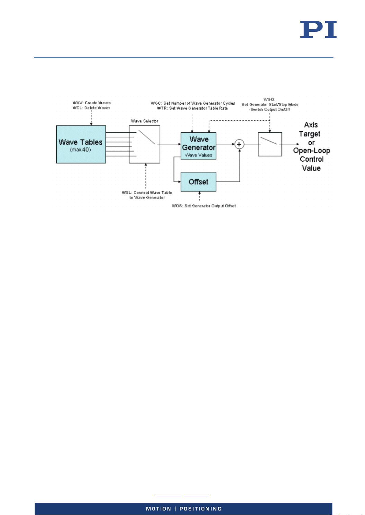
User Manual
E727T0005, valid for E-727
BRO, 2018-03-23
With WGR you can restart data recording while the wave generator is running. The recorded data
can be read with the DRR? command. See "Data Recording" (p. 64) for more information.
Figure 23: Block diagram of one wave generator
Application Notes
All wave generators can run simultaneously. All waveform output is synchronized because there is
a common pulse generator used by all wave generators. For that reasons, wave tables which are
supposed to run at the same time (each with one wave generator) should have the same length. If
the wave tables have different lengths, an output cycle will comprise only the number of points
given by the shortest table. This means that all waveform output is cut to the length of the
shortest waveform currently running.
Waveforms cannot be changed while they are being output by a wave generator. If you want to
modify a waveform with WAV, first stop any wave generator output from the associated wave
table.
The frequency of the wave generator output depends, among other factors, on the wave table
length. When you create waveforms, keep in mind that the usable frequency is limited by the
available amplifier power. If the frequency is too high, overheating of the amplifier(s) can occur,
and the piezo voltage output will be deactivated automatically.
When you use the wave generator to create white noise for a measurement (WAV command with
<WaveType> = "NOISE"), make sure that the wave table segment is at least as long as the duration
of the measurement. Otherwise, the noise sequence will be repeated during the measurement and
will no longer be white noise.
Wave generator output and analog control input:
It is possible to configure an axis for control by an analog input line while the wave generator
output is active for that axis. In that case, the wave generator will continue running, but its output
will no longer be used for control value generation. As long as the corresponding axis is set up to
be commanded by analog control input, you can stop the wave generator output, but not restart it.
Physik Instrumente (PI) GmbH & Co. KG, Auf der Roemerstrasse 1, 76228 Karlsruhe, Germany Page 95 / 228
Phone +49 721 4846-0, Fax +49 721 4846-1019, Email [email protected], www.pi.ws
Page 96

User Manual
E727T0005, valid for E-727
BRO, 2018-03-23
Wave generator output and move commands:
When the wave generator output is active, move commands like MOV or SVA are not allowed for
the associated axis.
See "Control Value Generation" (p. 30) for details.
When the wave generator is to be started by an external trigger signal (WGO bit 1 is set): For
reliable triggering, the pulse width of the input signal has to be at least 2 x the servo update time
of the E-727 (the servo update time is given in seconds by parameter 0x0E000200). The value of
the Wave Multi Start By Trigger parameter (ID 0x13000202) determines if the trigger is enabled
for only one generator start or for multiple starts. See "Wave Generator Started by Trigger Input"
(p. 104) for details and an example.
A wave generator outputs absolute values. In closed-loop operation (servo ON), the output is
interpreted as target positions in either case. In open-loop operation (servo OFF), the
interpretation of the wave generator output depends on the settings of the output matrix (see
"Output Generation" (p. 34) for more information). By default, the matrix is set up so that
commanded open-loop control values numerically correspond to axis position values.
Servo cannot be switched off (SVO) while a wave generator is running for the axis.
As long as a wave generator is running, it is not possible to change (WSL) or to delete (WCL) the
connected wave table (i.e. the waveform). The wave generator table rate (WTR), the number of
output cycles (WGC), the wave offset (WOS) and the output trigger settings (TWS) can be modified
while a wave generator is running.
When a wave generator finishes by running through a specified number of cycles completely, the
final position will be the first point of the waveform, unless the option "start at the endpoint of the
last cycle" was selected. In that case, the final position is the sum of the endpoint of the last output
cycle and any offset defined with WAV for the waveform.
When the wave generator is stopped within an output cycle by command, the axis will remain at
the last output position until a new position is commanded. If the wave generator is then
restarted, it will normally continue with the first point of the waveform, unless started with the
option "start wave generator output triggered by external signal", and the digital input line IN2
(see "Digital I/O Socket" (p. 220)) is used for triggering. In that case, the generator starts with the
first rising edge which is detected on this input line, and it will be stopped when a falling edge is
detected on this line. With the next rising edge, the generator output will continue at the
waveform point where it was stopped.
Wave generator output will continue even if the terminal or the program from which it was started
is quit or if the high voltage output is deactivated.
See the WGO command for more information.
The following data is always lost when the controller is powered down or rebooted:
Wave table content (WAV)
Assignment of wave tables to wave generators (WSL)
Output trigger settings (TWS)
Number of cycles for wave generator output (WGC)
The following settings can be saved with WPA to non-volatile memory, where they become the
power-on defaults (switch to command level 1 before with the CCL command):
Wave offset (WOS)
Wave generator table rate (WTR)
Physik Instrumente (PI) GmbH & Co. KG, Auf der Roemerstrasse 1, 76228 Karlsruhe, Germany Page 96 / 228
Phone +49 721 4846-0, Fax +49 721 4846-1019, Email [email protected], www.pi.ws
Page 97
User Manual
E727T0005, valid for E-727
BRO, 2018-03-23
INFORMATION
You can permanently save the settings of the wave generator in the E-727 with the macro
functionality of the E-727 (p. 115). You can also use a startup macro to configure the wave
generator and start the output each time that the E-727 is switched on or rebooted.
The different software interfaces provided for the controller also support use of the wave
generator. Waveforms can be defined, stored and displayed in and by the software in a more userfriendly way than in a terminal using WAV and WGO. If using the wave generator with the GCS DLL,
PIMikroMove or drivers for NI LabView software, read the descriptions in the associated software
manual first.
INFORMATION
It is recommended to use the PI Frequency Generator Tool or the PI Wave Generator Tool for
work with the wave generator (both available in PIMikroMove).
No command knowledge is necessary to work with PIMikroMove. The use of the PI Frequency
Generator Tool is described in the A000T0057 technical note. The use of the PI Wave
Generator Tool is described in the PIMikroMove manual (SM148E).
Physik Instrumente (PI) GmbH & Co. KG, Auf der Roemerstrasse 1, 76228 Karlsruhe, Germany Page 97 / 228
Phone +49 721 4846-0, Fax +49 721 4846-1019, Email [email protected], www.pi.ws
Page 98
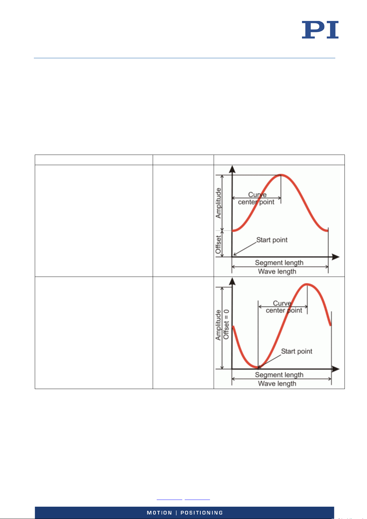
User Manual
WAV command
Comments
Waveform Segment
E727T0005, valid for E-727
BRO, 2018-03-23
Wave Generator Examples
The following examples can be reproduced using the command entry facilities of PIMikroMove or
PI Terminal. Note that it might be necessary to adapt them to your hardware configuration.
Defining Waveforms
Examples for how to define waveform segments for the wave tables, based on predefined curve
shapes (each WAV command defines a waveform segment which either replaces or is appended to
the waveform in the specified wave table):
Sine Curves
WAV 2 X SIN_P 2000 20 10 2000 0 1000
<WaveTableID> = 2
<AppendWave> = X
<WaveType> = SIN_P
<SegLength> = 2000
<Amp> = 20
<Offset> = 10
<WaveLength> = 2000
<StartPoint> = 0
<CurveCenterPoint> = 1000
WAV 2 X SIN_P 2000 30 0 2000 499 1000
<WaveTableID> = 2
<AppendWave> = X
<WaveType> = SIN_P
<SegLength> = 2000
<Amp> = 30
<Offset> = 0
<WaveLength> = 2000
<StartPoint> = 499
<CurveCenterPoint> = 1000
The previous contents
of the wave table are
overwritten by the
new segment,
waveform offset = 10
(Do not confuse with
the wave generator
output offset set with
WOS!),
symmetric curve
The previous contents
of the wave table are
overwritten by the
new segment,
symmetric curve
Physik Instrumente (PI) GmbH & Co. KG, Auf der Roemerstrasse 1, 76228 Karlsruhe, Germany Page 98 / 228
Phone +49 721 4846-0, Fax +49 721 4846-1019, Email [email protected], www.pi.ws
Page 99
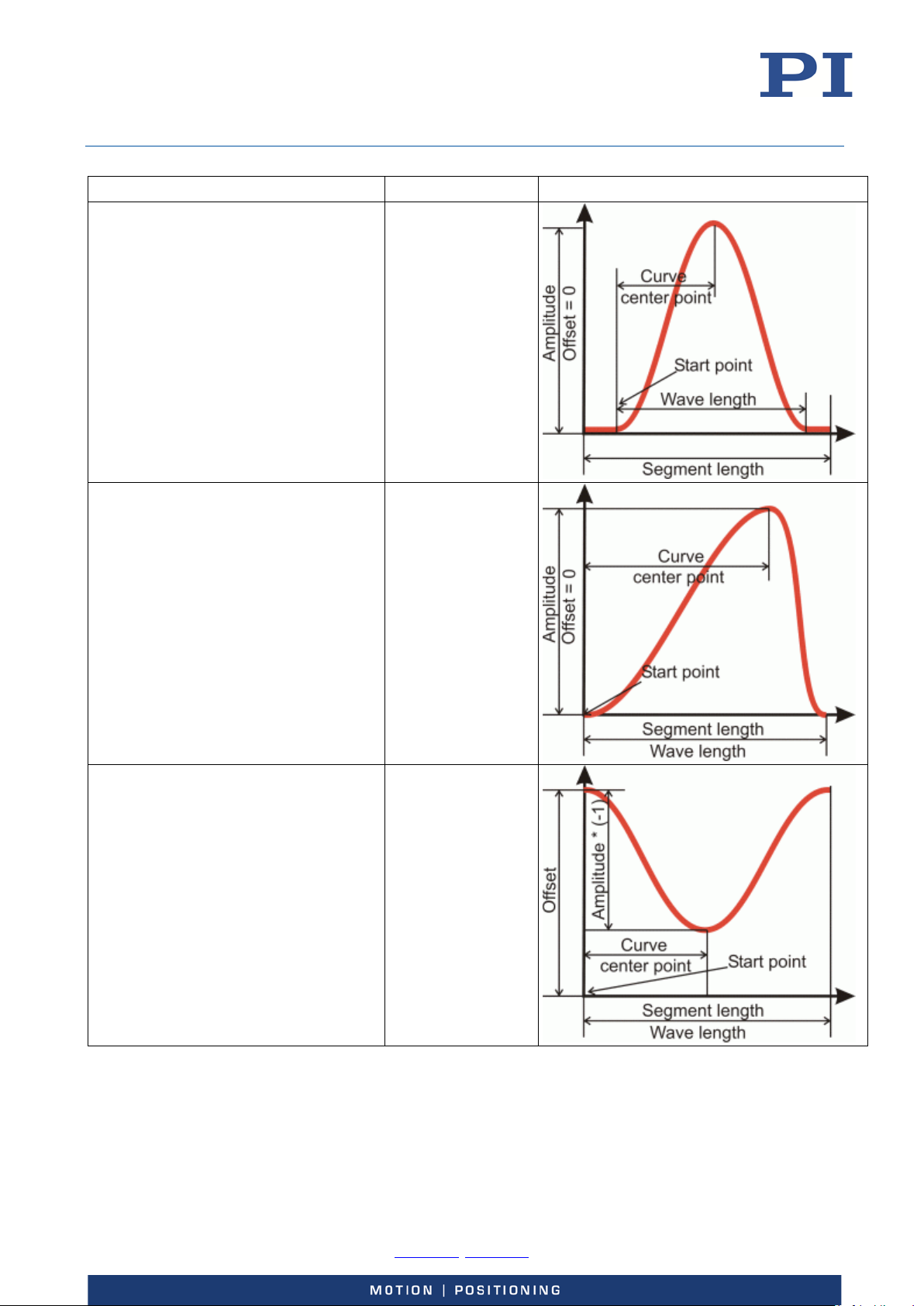
User Manual
E727T0005, valid for E-727
BRO, 2018-03-23
WAV command Comments Waveform Segment
WAV 2 & SIN_P 2000 25 0 1800 100 900
<WaveTableID> = 2
<AppendWave> = &
<WaveType> = SIN_P
<SegLength> = 2000
<Amp> = 25
<Offset> = 0
<WaveLength> = 1800
<StartPoint> = 100
<CurveCenterPoint> = 900
The defined segment
will be appended to
the existing wave
table contents,
symmetric curve
WAV 3 X SIN_P 4000 20 0 4000 0 3100
<WaveTableID> = 3
<AppendWave> = X
<WaveType> = SIN_P
<SegLength> = 4000
<Amp> = 20
<Offset> = 0
<WaveLength> = 4000
<StartPoint> = 0
<CurveCenterPoint> = 3100
WAV 2 X SIN_P 1000 -30 45 1000 0 500
<WaveTableID> = 2
<AppendWave> = X
<WaveType> = SIN_P
<SegLength> = 1000
<Amp> = -30
<Offset> = 45
<WaveLength> = 1000
<StartPoint> = 0
<CurveCenterPoint> = 500
The previous contents
of the wave table are
overwritten by the
new segment,
asymmetric curve
The previous contents
of the wave table are
overwritten by the
new segment,
negative-amplitude
curve,
symmetric curve
Physik Instrumente (PI) GmbH & Co. KG, Auf der Roemerstrasse 1, 76228 Karlsruhe, Germany Page 99 / 228
Phone +49 721 4846-0, Fax +49 721 4846-1019, Email [email protected], www.pi.ws
Page 100
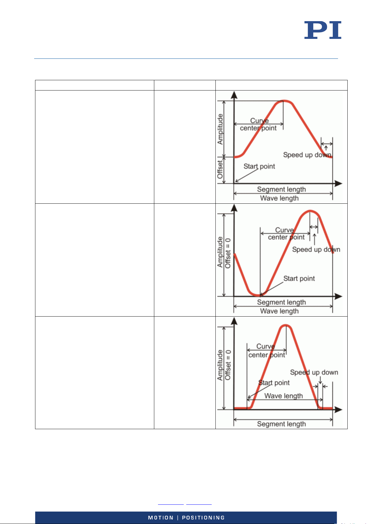
User Manual
E727T0005, valid for E-727
BRO, 2018-03-23
Ramp Curves
WAV command Comments Waveform Segment
WAV 4 X RAMP 2000 20 10 2000 0 300 1000
<WaveTableID> = 4
<AppendWave> = X
<WaveType> = RAMP
<SegLength> = 2000
<Amp> = 20
<Offset> = 10
<WaveLength> = 2000
<StartPoint> = 0
<SpeedUpDown> = 300
<CurveCenterPoint> = 1000
The previous contents
of the wave table are
overwritten by the
new segment,
waveform offset = 10
(Do not confuse with
the wave generator
output offset set with
WOS!)
symmetric curve
WAV 4 X RAMP 2000 35 0 2000 499 300 1000
<WaveTableID> = 4
<AppendWave> = X
<WaveType> = RAMP
<SegLength> = 2000
<Amp> = 35
<Offset> = 0
<WaveLength> = 2000
<StartPoint> = 499
<SpeedUpDown> = 300
<CurveCenterPoint> = 1000
WAV 5 X RAMP 2000 15 0 1800 120 150 900
<WaveTableID> = 5
<AppendWave> = X
<WaveType> = RAMP
<SegLength> = 2000
<Amp> = 15
<Offset> = 0
<WaveLength> = 1800
<StartPoint> = 120
<SpeedUpDown> = 150
<CurveCenterPoint> = 900
The previous contents
of the wave table are
overwritten by the
new segment,
symmetric curve
The previous contents
of the wave table are
overwritten by the
new segment,
symmetric curve
Physik Instrumente (PI) GmbH & Co. KG, Auf der Roemerstrasse 1, 76228 Karlsruhe, Germany Page 100 / 228
Phone +49 721 4846-0, Fax +49 721 4846-1019, Email [email protected], www.pi.ws
 Loading...