

Page 1
SERVICE MANUAL
LIFEPAK
®
15
MONITOR/DEFIBRILLATOR
MIN
© 2011 Physio-Control, Inc. All rights reserved.
3309059-000
Page 2

LIFEPAK 15 Monitor/Defibrillator Section Menu
1 Introduction
page 11
2 Safety
page 29
3 Device Description
page 48
4 Modes of Operation
page 89
5 Performance Inspection Procedures
page 98
6 Test and Calibration Procedures (TCP)
page 188
7 Troubleshooting
page 218
8 Preventive Maintenance
page 265
9 Battery Maintenance
page 278
10 Replacement Procedures
page 289
11 Assembly Diagrams and Parts Lists
page 486
Performance Procedure Checklist
page 647
Section Navigator
Back
Index
ii
Page 3

LIFEPAK 15 Monitor/Defibrillator
Table of Contents
Service Manual
Table of Contents
Section Navigator ........................................................................................................................................................................ ii
Introduction .............................................................................................................................................................................. 11
Trademarks ..................................................................................................................................................................... 12
Using Adobe Reader......................................................................................................................................................... 13
Navigating Through the Manual......................................................................................................................................... 14
Service Personnel Qualifications........................................................................................................................................ 15
Contacting Physio-Control ................................................................................................................................................ 16
Responsibility for Information ........................................................................................................................................... 17
Device Tracking ............................................................................................................................................................... 18
Service Information.......................................................................................................................................................... 19
Recycling Information ...................................................................................................................................................... 20
Warranty ......................................................................................................................................................................... 21
Configuration Information ................................................................................................................................................. 22
Glossary .......................................................................................................................................................................... 23
Acronyms ........................................................................................................................................................................ 25
Safety....................................................................................................................................................................................... 29
Terms ............................................................................................................................................................................. 30
General Warnings............................................................................................................................................................. 31
Symbols.......................................................................................................................................................................... 36
Device Description..................................................................................................................................................................... 48
Introduction .................................................................................................................................................................... 49
Physical Description and Features ..................................................................................................................................... 54
Devices, Options, Supplies, and Accessories ...................................................................................................................... 65
System Context Diagrams ................................................................................................................................................. 70
Functional Descriptions .................................................................................................................................................... 74
Section Menu
Back
Index
iii
Page 4

LIFEPAK 15 Monitor/Defibrillator
Table of Contents
Service Manual
Modes of Operation.................................................................................................................................................................... 89
Manual Mode .................................................................................................................................................................. 90
AED Mode ...................................................................................................................................................................... 91
Setup Mode..................................................................................................................................................................... 92
Service Mode................................................................................................................................................................... 94
Demo Mode..................................................................................................................................................................... 96
Archive Mode .................................................................................................................................................................. 97
Performance Inspection Procedures............................................................................................................................................. 98
PIP – Scope and Applicability ......................................................................................................................................... 100
PIP – Resource Requirements ......................................................................................................................................... 101
PIP – Test Equipment Requirements .............................................................................................................................. 102
Manual Mode Access...................................................................................................................................................... 106
PIP – Device Preparation ............................................................................................................................................... 110
Power Management........................................................................................................................................................ 114
PIP – User Test and Date/Time Verification ...................................................................................................................... 118
Miscellaneous Functions ................................................................................................................................................ 119
PIP – Printer Tests......................................................................................................................................................... 133
PIP – Keypad Tests ........................................................................................................................................................ 136
PIP – Audio Test............................................................................................................................................................ 137
PIP – Invasive Pressure Verification - P1, P2 .................................................................................................................... 138
PIP – SpO2/SpCO/SpMet Test......................................................................................................................................... 140
PIP – Recording Operating Data (Optional) ....................................................................................................................... 141
PIP – ECG Performance Testing ...................................................................................................................................... 142
PIP – Defibrillator/Pacing Testing .................................................................................................................................... 151
PIP – QUIK-COMBO ECG Characteristic Tests .................................................................................................................. 156
PIP – Standard Paddles User Test ................................................................................................................................... 159
PIP – Standard Paddles Defibrillator Delivered Energy Tests .............................................................................................. 161
PIP – Patient Impedance Test ......................................................................................................................................... 171
Section Menu
Back
Index
iv
Page 5

LIFEPAK 15 Monitor/Defibrillator
Table of Contents
Service Manual
Data Management.......................................................................................................................................................... 172
PIP – Leakage Current Tests .......................................................................................................................................... 177
PIP – Disabling/Resetting Maintenance Prompt ................................................................................................................ 187
Test and Calibration Procedures (TCP) ....................................................................................................................................... 188
TCP – Scope and Applicability ........................................................................................................................................ 189
TCP – Resource Requirements ........................................................................................................................................ 190
TCP – Test Equipment Requirements............................................................................................................................... 191
TCP – Setup .................................................................................................................................................................. 193
TCP – Service/Calibration Submenu Access ...................................................................................................................... 194
TCP – Temperature Calibration Test................................................................................................................................. 195
TCP – Defibrillator Energy Tests ...................................................................................................................................... 199
TCP – Defibrillator Output Waveform Test ........................................................................................................................ 203
TCP – Defibrillator Isolation Test ..................................................................................................................................... 206
TCP – CO2 Calibration.................................................................................................................................................... 207
TCP – Printer Calibration Tests........................................................................................................................................ 210
TCP – Pacer Characteristics Tests.................................................................................................................................... 213
TCP – LIFENET Device Communications Setup................................................................................................................. 216
Troubleshooting....................................................................................................................................................................... 218
Troubleshooting Chart .................................................................................................................................................... 219
Using the Service/Status Features ................................................................................................................................... 226
Device Log ............................................................................................................................................................... 228
Device Data................................................................................................................................................................... 230
Service Log ................................................................................................................................................................... 233
Processing Service Log Codes ......................................................................................................................................... 235
Counters ....................................................................................................................................................................... 236
Clear Memory ................................................................................................................................................................ 238
Service Log Code Categories ........................................................................................................................................... 239
Utility Service Codes ...................................................................................................................................................... 241
Section Menu
Back
Index
v
Page 6

LIFEPAK 15 Monitor/Defibrillator
Table of Contents
Service Manual
User Interface Service Codes .......................................................................................................................................... 242
Data Management Service Codes..................................................................................................................................... 244
System Monitor Service Codes ........................................................................................................................................ 245
Processor Control Service Codes ...................................................................................................................................... 246
ECG Service Codes......................................................................................................................................................... 248
Patient Parameter Service Codes ..................................................................................................................................... 249
Therapy Service Codes.................................................................................................................................................... 250
Printer Service Codes ..................................................................................................................................................... 257
Power Management Service Codes................................................................................................................................... 258
Serial Communication Service Codes ............................................................................................................................... 259
Corrective Action Codes.................................................................................................................................................. 260
Service LED .................................................................................................................................................................. 263
Display Pixels Test ......................................................................................................................................................... 264
Preventive Maintenance ........................................................................................................................................................... 265
Device Self Tests ........................................................................................................................................................... 266
Device User Test............................................................................................................................................................ 267
Preventive Maintenance and Testing Schedule.................................................................................................................. 268
Scheduled Replacement Items........................................................................................................................................ 269
Setting/Resetting the Maintenance Prompt Interval ........................................................................................................... 270
Device Useful Life.......................................................................................................................................................... 271
Support Policy ............................................................................................................................................................... 272
Cleaning ....................................................................................................................................................................... 273
Environmental Conditions ............................................................................................................................................... 275
A12 Printer Maintenance................................................................................................................................................ 276
Battery Maintenance ................................................................................................................................................................ 278
Battery General Characteristics ....................................................................................................................................... 279
Battery Status Indicators ................................................................................................................................................ 280
Battery Performance Characteristics ................................................................................................................................ 283
Section Menu
Back
Index
vi
Page 7

LIFEPAK 15 Monitor/Defibrillator
Table of Contents
Service Manual
Charging the Batteries Using the Station or Mobile Li-ion Battery Charger ........................................................................... 284
Discarding/Recycling Batteries ........................................................................................................................................ 285
Storing Batteries............................................................................................................................................................ 286
Receiving New Batteries ................................................................................................................................................. 287
Coin Cell Battery............................................................................................................................................................ 288
Replacement Procedures .......................................................................................................................................................... 289
Summary of Replacement Procedures .............................................................................................................................. 290
Warnings and Cautions ................................................................................................................................................... 293
Static-Sensitive Device Handling ..................................................................................................................................... 294
Tools List ...................................................................................................................................................................... 296
Capacitor Discharge Tool ................................................................................................................................................ 297
Capacitor Discharging Procedure ..................................................................................................................................... 298
Discharging the C15 Pacing Capacitor ............................................................................................................................. 299
Saving and Restoring the Setup Configuration .................................................................................................................. 300
Disassembling the Case.................................................................................................................................................. 301
Reassembling the Case................................................................................................................................................... 304
Inside Front Case Diagram .............................................................................................................................................. 309
Interface PCB (A05) Replacement................................................................................................................................... 310
Backlight PCB (A08) Replacement .................................................................................................................................. 315
Printer Control Keypad (A09) Replacement ...................................................................................................................... 318
Main Keypad (A10) Replacement .................................................................................................................................... 320
Display Shield Replacement ........................................................................................................................................... 322
LCD Display Assembly (A11) Replacement ....................................................................................................................... 324
Display Lens Replacement.............................................................................................................................................. 326
Front Case Replacement................................................................................................................................................. 328
System/Interface PCB Cable (W04) Replacement.............................................................................................................. 332
Backlight/Interface PCB Cable (W06) Replacement........................................................................................................... 333
Therapy Connector Cable (W11) Replacement .................................................................................................................. 334
Section Menu
Back
Index
vii
Page 8

LIFEPAK 15 Monitor/Defibrillator
Table of Contents
Service Manual
Printer Control Keypad/Interface PCB Cable (W12) Replacement........................................................................................ 336
Main Keypad/Interface PCB Cable (W13) Replacement...................................................................................................... 337
Speed Dial Assembly (W15) Replacement: ....................................................................................................................... 338
Installing the Speed Dial Assembly (W15) ........................................................................................................................ 340
Printer Assembly/Interface PCB Cable (W16) Replacement ................................................................................................ 341
Speaker Assembly (W17) Replacement ............................................................................................................................ 343
LCD Display Assembly/Interface PCB Cable (W18) Replacement ........................................................................................ 346
Printer Assembly/Chassis Ground Cable (W19) Replacement.............................................................................................. 347
Inside Rear Case Diagrams ............................................................................................................................................. 348
System (A01)/Therapy (A04) PCB Assembly Replacement ................................................................................................. 352
Installing the System (A01)/Therapy (A04) PCB Assembly ................................................................................................. 359
Power PCB (A03) Replacement ....................................................................................................................................... 373
OEM PCB (A06) Replacement......................................................................................................................................... 381
Transfer Relay Assembly (A13) Replacement.................................................................................................................... 388
Energy Storage Capacitor (A15) Replacement ................................................................................................................... 391
SpO2 PCB (A16) Replacement........................................................................................................................................ 394
Interconnect Bracket (A17) Replacement......................................................................................................................... 404
NIBP (A21)/CO2 (A23) Module Replacement ................................................................................................................... 407
Biphasic Module (A22)/Inductive Resistor (A14) Replacement ........................................................................................... 418
EMI Shield Replacement ................................................................................................................................................ 425
NIBP Connector Replacement ......................................................................................................................................... 426
Parameter Bezel Replacement......................................................................................................................................... 429
Rear Case Replacement.................................................................................................................................................. 435
Handle Replacement...................................................................................................................................................... 441
Paddle Retainer Cover Replacement ................................................................................................................................ 442
Power/System PCB Cable (W01) Replacement .................................................................................................................. 443
Power/Therapy PCB Cable (W02) Replacement ................................................................................................................. 444
Power/Contact PCB Cable (W05) Replacement ................................................................................................................. 446
Section Menu
Back
Index
viii
Page 9

LIFEPAK 15 Monitor/Defibrillator
Table of Contents
Service Manual
ECG Connector Cable (W07) Replacement ....................................................................................................................... 448
System Connector Cable (W08) and Auxiliary Connector Cable (W09) Replacement ............................................................. 451
Battery Pins / Power PCB Cable (W10) Replacement ......................................................................................................... 454
USB Flex Module (W14) Replacement ............................................................................................................................. 458
Biphasic Cable (W20) Replacement................................................................................................................................. 460
OEM PCB/SpO2 (W21) Module Cable Replacement .......................................................................................................... 462
SpO2 Connector Cable (W22) Replacement...................................................................................................................... 464
OEM PCB/CO2 Module Cable (W26) Replacement ............................................................................................................ 466
OEM PCB/NIBP Module Cable (W27) Replacement........................................................................................................... 468
CO2 Inlet Connector Cable (W28) Replacement ................................................................................................................ 470
CO2 Adapter Cable (W30) Replacement........................................................................................................................... 473
Invasive Pressure Connector Assembly (W33) Replacement................................................................................................ 475
Temperature Cable Assembly (W35) Replacement............................................................................................................. 477
Contact PCB (A07) Replacement..................................................................................................................................... 479
Printer Assembly (A12) Replacement............................................................................................................................... 480
Coin Battery Replacement .............................................................................................................................................. 482
Battery Pin Replacement ................................................................................................................................................ 484
Software and Device Upgrades ....................................................................................................................................... 485
Assembly Diagrams and Parts Lists............................................................................................................................................ 486
Section Glossary ............................................................................................................................................................ 487
Main Diagrams .............................................................................................................................................................. 488
External Parts Diagrams and Lists ................................................................................................................................... 491
Front Parts Diagrams and Parts List................................................................................................................................. 497
System/Therapy PCB Assembly Diagrams and Parts Lists................................................................................................... 506
Parameter Bezel Diagrams and Parts Lists........................................................................................................................ 511
Rear Diagrams and Parts List .......................................................................................................................................... 519
OEM Optional Assemblies, Diagrams and Parts Lists ......................................................................................................... 532
Label Language Parts ..................................................................................................................................................... 537
Section Menu
Back
Index
ix
Page 10

LIFEPAK 15 Monitor/Defibrillator
Table of Contents
Service Manual
Connection Diagrams for Assemblies, Control Boards, Cables, and Connectors ..................................................................... 562
Repair Kits.................................................................................................................................................................... 610
Defibrillator Part Number and Serial Number.................................................................................................................... 638
Ordering Parts ............................................................................................................................................................... 639
Index...................................................................................................................................................................................... 640
Section Menu
Back
Index
x
Page 11

LIFEPAK 15 Monitor/Defibrillator
Introduction
1
Service Manual
Introduction
This service manual describes how to maintain, test, troubleshoot, and repair the LIFEPAK 15 monitor/defibrillator. A separate publication, the
LIFEPAK 15 Monitor/Defibrillator Operating Instructions, is for use by physicians, clinicians, and emergency care providers. The operating
instructions provide step-by-step instructions as well as operator-level testing and maintenance.
NOTE: Hyperlinks appear in “blue text.” Text that indicates the name of a button, menu item, or screen message appears in all
caps (for example, press ANALYZE, select MANUAL MODE.
This section covers the following topics:
• Trademarks (p. 12)
• Using Adobe Reader (p. 13)
• Navigating Through the Manual (p. 14)
• Service Personnel Qualifications (p. 15)
• Contacting Physio-Control (p. 16)
• Responsibility for Information (p. 17)
• Device Tracking (p. 18)
• Service Information (p. 19)
• Recycling Information (p. 20)
• Warranty (p. 21)
• Configuration Information (p. 22)
• Glossary (p. 23)
• Acronyms (p. 25)
Contents
Section Menu
Back
Index
11
Page 12

LIFEPAK 15 Monitor/Defibrillator
MIN
Introduction
Trademarks
1
Service Manual
Trademarks
LIFEPAK, LIFEPAK CR, LIFEPAK EXPRESS, LIFENET, FASTPAK, LIFE•PATCH, QUIK-COMBO, and DERMA-JEL are registered trademarks of
Physio-Control, Inc. CODE SUMMARY, CODE-STAT, PARTSLINE, REDI-PAK, Shock Advisory System, SunVue, and DT EXPRESS are trademarks
of Physio-Control, Inc. Microsoft and Windows are registered trademarks of Microsoft Corporation in the US and/or other countries. Adobe is a
trademark of Adobe Systems Incorporated. Masimo, the Radical logo, Rainbow, and SET are registered trademarks of Masimo Corporation. Red,
LNCS, SpCO, and SpMet are trademarks of Masimo Corporation. CapnoLine and FilterLine are registered trademarks of Oridion Medical, Ltd. The
Oridion medical capnography in this product is covered by one or more of the following US patents: 6,428,483; 6,997,880; 5,300,859;
6,437,316 and their foreign equivalents. Additional patent applications pending. Fluke and BIO-TEK are registered trademarks and QED-6H is a
trademark of Fluke Biomedical Corporation. Bluetooth is a registered trademark of Bluetooth SIG, Inc. CASMED is a registered trademark of CAS
Medical Systems, Inc. SIGNAGEL is a registered trademark of Parker Laboratories. EDGE System Technology is a trademark of Ludlow Technical
Products. Specifications are subject to change without notice.
© 2011 Physio-Control, Inc. All rights reserved.
3309059-000
Section Menu Section Contents Back Index
12
Page 13

LIFEPAK 15 Monitor/Defibrillator
Service Manual
Using Adobe Reader
Accessing Adobe Reader Help
This service manual opens in Adobe Reader, which is included on this documentation CD. For additional assistance using the
Adobe Reader program, access ADOBE READER HELP in the HELP menu.
Using Bookmarks
Bookmarks appear in a column on the left side of the screen. They enable you to easily navigate to main sections of the manual,
similar to a table of contents.
To view or hide the bookmarks column, click the BOOKMARKS tab located along the left side of the screen.
To jump to a bookmark topic, click the desired topic.
NOTE: A plus sign to the left of a bookmark topic indicates additional topics exist under that bookmark level. Click the plus sign to
expand or collapse the bookmarks.
Introduction
Using Adobe Reader
1
Using Page View
Click the PAGES tab located to the far left of the screen to view miniature images of each page in the document. Scroll through the
pages and click an image to jump quickly to that page.
Section Menu Section Contents Back Index
13
Page 14

LIFEPAK 15 Monitor/Defibrillator
Back
Section Menu
Section Contents
Back
Index
Navigating Through the Manual
Introduction
1
Service Manual
Navigating Through the Manual
Blue text indicates a hyperlink. Click a link to jump to that topic or page. Click in the navigation bar (at the bottom of each page)
to return to your previous location. The pointer changes to a pointing finger when positioned over a link. A navigation bar at the bottom of
each page also provides helpful links.
The navigation bar includes:
• Click to jump to the main table of contents for the manual.
• Click to jump to the table of contents for the section you are currently viewing.
• Click to retrace your steps in a document, returning to each page in the reverse order visited.
• Click to jump to the manual’s index.
Section Menu Section Contents Back Index
14
Page 15

LIFEPAK 15 Monitor/Defibrillator
Service Manual
Service Personnel Qualifications
Service technicians must be properly qualified and thoroughly familiar with the operation of the LIFEPAK 15 monitor/defibrillator.
They must meet at least one of the following requirements (or the equivalent):
• Associate of Applied Science, with an emphasis in biomedical electronics
• Certificate of Technical Training, with an emphasis in biomedical electronics
• Equivalent biomedical electronics experience
Introduction
Service Personnel Qualifications
1
Section Menu Section Contents Back Index
15
Page 16

LIFEPAK 15 Monitor/Defibrillator
Service Manual
Contacting Physio-Control
Physio-Control, Inc.
11811 Willows Road NE
Redmond, WA 98052-2003 USA
Telephone: 425.867.4000
Toll Free (USA only): 800.442.1142
Fax: 1.425.867.4861
Internet: www.physio-control.com
Introduction
Contacting Physio-Control
1
Section Menu Section Contents Back Index
16
Page 17

LIFEPAK 15 Monitor/Defibrillator
Responsibility for Information
Introduction
1
Service Manual
Responsibility for Information
This service manual describes the methods required to maintain, test, and repair the LIFEPAK 15 monitor/defibrillator. This manual does not
address the operation of the device. Qualified service personnel (see Service Personnel Qualifications on page 15) must consult this manual and
the LIFEPAK 15 Monitor/Defibrillator Operating Instructions to obtain a complete understanding of the use and maintenance of the device.
It is the responsibility of our customers to ensure that the appropriate person(s) within their organization has access to the information in this
service manual, including any warnings and cautions used throughout the manual.
Section Menu Section Contents Back Index
17
Page 18

LIFEPAK 15 Monitor/Defibrillator
!USA
Introduction
Device Tracking
1
Service Manual
Device Tracking
Device Tracking:
The U.S. Food and Drug Administration requires defibrillator manufacturers and distributors to track the location of their defibrillators. If the
device is located somewhere other than the shipping address or the device has been sold, donated, lost, stolen, exported, destroyed, permanently
retired from use, or if the device was not obtained directly from Physio-Control, please do one of the following: register the device at http://
www.physio-control.com, call the device registration phone line at 1.800.426.4448, or use one of the postage-paid address change cards
located in the back of the LIFEPAK 15 Monitor/Defibrillator Operating Instructions, to update this vital tracking information.
Section Menu Section Contents Back Index
18
Page 19

LIFEPAK 15 Monitor/Defibrillator
Service Manual
Service Information
Before attempting to clean or repair any assembly in the device, the service technician should be familiar with the information
provided in Preventive Maintenance (p. 265).
A qualified service technician (see Service Personnel Qualifications on page 15) should inspect any device that has been dropped,
damaged, or abused to verify that the device is operating within performance standards listed in the Performance Inspection
Procedures (p. 98) (PIP) section, and that the leakage current values are acceptable.
Replacement procedures for the device are limited to those items accessible at the final assembly level. Replacements and
adjustments must be made by qualified service personnel. Replacements at the final assembly level simplify repair and servicing
procedures and help ensure correct device operation and calibration.
To obtain service and maintenance for your device, contact your local Physio-Control service or sales representative. In the USA,
call Physio-Control Technical Support at 1.800.442.1142. Outside the USA, contact your local Physio-Control representative.
When you call Physio-Control to request service, provide the following information:
• Model number and part number
• Serial number
• Observation of the problem that led to the call
Introduction
Service Information
1
Section Menu Section Contents Back Index
19
Page 20

LIFEPAK 15 Monitor/Defibrillator
Service Manual
Recycling Information
Recycle the device at the end of its useful life.
• Recycling assistance – The device should be recycled according to national and local regulations. For instructions on disposing
of this product or its accessories, see http://recycling.medtronic.com.
• Preparation – The device should be clean and contaminant-free prior to being recycled.
• Recycling of disposable electrodes – After using disposable electrodes, follow your local clinical procedures for recycling.
• Recycling of batteries – The device uses rechargeable Lithium-ion batteries. Follow local guidelines and instructions provided in
this service manual for discarding and recycling batteries as described in Discarding/Recycling Batteries (p. 285)
• Packaging – packaging should be recycled according to national and local regulations.
Introduction
Recycling Information
1
Section Menu Section Contents Back Index
20
Page 21

LIFEPAK 15 Monitor/Defibrillator
Introduction
Warranty
1
Service Manual
Warranty
Refer to the warranty statement included with the product. For duplicate copies, contact your local Physio-Control representative. In the US, call
1.800.442.1142. Outside the USA, contact your local Physio-Control representative.
Using defibrillation electrodes, adapter devices, or other parts and supplies from sources other than Physio-Control is not recommended. PhysioControl has no information regarding the performance or effectiveness of its LIFEPAK defibrillators if they are used in conjunction with
defibrillation electrodes or other parts and supplies from other sources. If device failure is attributable to defibrillation electrodes or other parts or
supplies not manufactured by Physio-Control, this may void the warranty.
Section Menu Section Contents Back Index
21
Page 22

LIFEPAK 15 Monitor/Defibrillator
Service Manual
Configuration Information
This service manual is relevant for the following devices and options:
• LIFEPAK 15 monitor/defibrillator Version 1 (V1) device without auxiliary power option
• LIFEPAK 15 monitor/defibrillator Version 2 (V2) device with auxiliary power option
• ECG monitoring — standard
• Manual mode defibrillation — standard
• AED mode — standard
• Noninvasive pacing — standard
• Bluetooth
• 12-lead ECG option
• Oridion
• Masimo
• CASMED
• 2 Channel Invasive pressure option
• Vital signs and ST trending option
• Temperature monitoring option (V2 only; temperature option and invasive pressure option cannot be installed on the same
device)
®
wireless technology option (within approved countries)
®
CO2 option
®
SpO2/SpCO™/SpMet™ options
®
NIBP monitoring option
Introduction
Configuration Information
1
Section Menu Section Contents Back Index
22
Page 23

LIFEPAK 15 Monitor/Defibrillator
Service Manual
Introduction
Glossary
1
Glossary
The following are definitions of terms used throughout this service manual.
• Biphasic waveform — Characterized by a positive current phase followed by a reverse current phase of shorter duration and
• Automated external defibrillator (AED) — An Automated ECG analysis and a prompted treatment protocol for patients in cardiac
• Shock Advisory System (SAS) — A computerized ECG analysis system used in AED mode for detecting a shockable rhythm. For
• Continuous patient surveillance system (CPSS) — A feature that monitors the patient ECG in LEADS or PADDLES for a
• CODE SUMMARY
• CO2 monitor — An optional noninvasive capnometer that monitors CO2, EtCO2, FiCO2, and respiration rate (referred to
• End-tidal carbon dioxide (EtCO2) — EtCO2 is the measurement of CO2 at the end of expiration.
• Event log summary — A report summarizing important events for a particular patient record; part of the CODE SUMMARY
decreased magnitude. The waveform pulse characteristic is biphasic truncated exponential (BTE).
arrest.
more information about SAS, see Appendix C in the operating instructions.
potentially shockable rhythm. CPSS is active when the VF/VT ALARM is selected ON (Setup/Alarms) or after pressing the
ALARMS button. For more information about CPSS, see Appendix C in the operating instructions.
™
report — A summary report that includes the ECG segments associated with key events, such as analysis or
shock. See “Data Management” in the operating instructions for a sample CODE SUMMARY report.
henceforth as CO2).
report.
• Noninvasive blood pressure (NIBP) — An optional oscillometric measurement of systolic, diastolic, and mean arterial blood
pressure, along with pulse rate.
• Noninvasive pacing — A standard feature that delivers repetitive electrical stimuli to the heart through large adhesive electrodes
placed on the patient’s chest.
Section Menu Section Contents Back Index
23
Page 24

LIFEPAK 15 Monitor/Defibrillator
Service Manual
Introduction
Glossary
1
• QUIK-COMBO
and defibrillation therapy to the patient.
• QUIK-COMBO patient simulator — A combination QC therapy cable and ECG lead cardiac rhythm simulator. The simulator is
designed for use in training clinical personnel to operate the LIFEPAK 15 monitor/defibrillator.
• Pulse Co-oximeter — An optional noninvasive pulse oximeter that measures the saturation of oxygen in arterial blood,
carboxyhemoglobin and methemoglobin concentrations, respectively.
• SpO2/SpCO/SpMet — The measure of functional oxygen saturation (SpO2), carboxyhemoglobin concentration (SpCO), and
methemoglobin concentration (SpMet) in the blood.
• Test Load — An accessory shipped with the LIFEPAK monitor/defibrillator that connects to the QUIK-COMBO therapy cable. It
provides a 50 ohm load for shock discharge through the therapy cable.
• Vital sign (VS) and ST segment Trends — An optional trending feature that can graphically display and document a patient's
vital signs and ST segment measurements for up to eight hours.
®
pacing/defibrillation/ECG electrodes — An electrode system that allows monitoring of ECG, delivery of pacing
Section Menu Section Contents Back Index
24
Page 25

LIFEPAK 15 Monitor/Defibrillator
Service Manual
Acronyms
Table 1.1 lists acronyms and abbreviations used in this manual.
Table 1.1— Acronyms and Abbreviations
Term Description
AAMI Association for the Advancement of Medical Instrumentation
ADC Analog-to-digital conversion
AED Automated external defibrillator
Ah Ampere hour
AHA American Heart Association
AMI Acute myocardial infarction
Introduction
Acronyms
1
ANSI American National Standards Institute
ASIC Application-specific integrated circuit
BF Electrically isolated, external body connection
BPM Beats per minute
BTE Biphasic truncated exponential
CF Electrically isolated, direct cardiac connection
CO2 Carbon dioxide
Section Menu Section Contents Back Index
25
Page 26

LIFEPAK 15 Monitor/Defibrillator
Service Manual
Table 1.1— Acronyms and Abbreviations (Continued)
CPR Cardiopulmonary resuscitation
CPU Central processing unit
CPSS Continuous patient surveillance system
DDE Disposable defibrillation electrodes
DMM Digital multimeter
DSP Digital signal processor
DUART Dual universal asynchronous receiver/transmitter
ECG Electrocardiogram
EMS Emergency medical service
ESCC Energy storage capacitor charger
Introduction
Acronyms
1
ESD Electrostatic discharge
ESU Electrosurgical unit
EtCO2 End-tidal carbon dioxide
FiCO2 Inspired carbon dioxide
HR Heart rate
IEC International Electrical Commission
IP Invasive pressure
LCD Liquid crystal display
Section Menu Section Contents Back Index
26
Page 27

LIFEPAK 15 Monitor/Defibrillator
Service Manual
Table 1.1— Acronyms and Abbreviations (Continued)
LED Light-emitting diode
Li-ion Lithium-ion
mmHg Millimeters of mercury
NIBP Noninvasive blood pressure
NSR Normal sinus rhythm
OEM Original equipment manufacturer
RR Respiration rate
PC Personal computer
PCB Printed circuit board
PIP Performance inspection procedure
Introduction
Acronyms
1
PPM Pulses per minute
PR Pulse rate
QRS Refers to portions of the ECG waveform
RTC/NVRAM Real-time clock/non-volatile random-access memory
RTS Radio transparent system
SAS Shock Advisory System
SBC Single-Board Computer
SpCO Measurement of carboxyhemoglobin concentration
Section Menu Section Contents Back Index
27
Page 28

LIFEPAK 15 Monitor/Defibrillator
Service Manual
Table 1.1— Acronyms and Abbreviations (Continued)
SpO2 Measurement of oxygen saturation
SpMet Measurement of methemoglobin concentration
SSD Static-sensitive device
TCP Test and calibration procedure
USB Universal serial bus
VF Ventricular fibrillation
VS Vital signs
VT Ventricular tachycardia
μA MicroAmpere
.
Introduction
Acronyms
1
Section Menu Section Contents Back Index
28
Page 29

LIFEPAK 15 Monitor/Defibrillator
Safety
2
Service Manual
Safety
This section describes the general safety conventions, terms, and symbols used in this service manual or on the LIFEPAK 15 monitor/defibrillator
front and rear panels. This information is intended to alert service personnel to recommended precautions in the care, use, and handling of this
medical device.
• Terms (p. 30)
• General Warnings (p. 31)
• Symbols (p. 36)
Contents
Section Menu
Back
Index
29
Page 30

LIFEPAK 15 Monitor/Defibrillator
Safety
Terms
2
Service Manual
Terms
The following terms are used in this service manual or on the various configurations of the LIFEPAK 15 monitor/defibrillator (device). Familiarize
yourself with their definitions and significance.
DANGER
Immediate hazards that will result in serious personal injury or death.
WARNING
Hazards or unsafe practices that may result in serious personal injury or death.
CAUTION
Hazards or unsafe practices that may result in minor personal injury, product
damage, or property damage.
Section Menu Section Contents Back Index
30
Page 31

LIFEPAK 15 Monitor/Defibrillator
General Warnings
Safety
2
Service Manual
General Warnings
The following are general danger, warning, and caution statements. Keep them in mind when working with the LIFEPAK 15 monitor/defibrillator
(device). Additional specific warnings and cautions appear throughout this service manual and the LIFEPAK 15 Monitor/Defibrillator Operating
Instructions.
DANGER
EXPLOSION HAZARD
Do not use this defibrillator in the presence of flammable gases or
anesthetics.
SHOCK HAZARD
Do not disassemble the defibrillator. It contains no operator serviceable
components and lethal voltages may be present. Contact authorized
service personnel for repair.
Section Menu Section Contents Back Index
31
Page 32

LIFEPAK 15 Monitor/Defibrillator
Service Manual
WARNINGS
SHOCK OR FIRE HAZARDS
SHOCK HAZARD
The defibrillator delivers up to 360 joules of electrical energy. Unless
properly used as described in these operating instructions, this
electrical energy may cause serious injury or death. Do not attempt to
operate this device unless thoroughly familiar with these operating
instructions and the function of all controls, indicators, connectors, and
accessories.
SHOCK OR FIRE HAZARD
Do not immerse any portion of this defibrillator in water or other fluids.
Avoid spilling any fluids on defibrillator or accessories. Spilled liquids
may cause the defibrillator and accessories to perform inaccurately or
fail. Do not clean with ketones or other flammable agents. Do not
autoclave or sterilize this defibrillator or accessories unless otherwise
specified.
Safety
General Warnings
2
POSSIBLE FIRE
Use care when operating this device close to oxygen sources (such as
bag-valve-mask devices or ventilator tubing). Turn off gas source or
move source away from patient during defibrillation.
Section Menu Section Contents Back Index
32
Page 33

LIFEPAK 15 Monitor/Defibrillator
Service Manual
WARNINGS (CONTINUED)
ELECTRICAL INTERFERENCE HAZARDS
POSSIBLE ELECTRICAL INTERFERENCE WITH DEVICE PERFORMANCE
Equipment operating in close proximity may emit strong
electromagnetic or radio frequency interference (RFI), which could
affect the performance of this device. If use of equipment in close
proximity is necessary, observe the device to verify normal operation in
the configuration in which the device will be used. RFI may result in
distorted ECG, incorrect ECG lead status, failure to detect a shockable
rhythm, cessation of pacing, or incorrect vital sign measurements. Avoid
operating the device near cauterizers, diathermy equipment, or other
portable and mobile RF communications equipment. Do not rapidly key
EMS radios on and off. Refer to Appendix D in the Operating
Instructions for recommended distances of equipment. Contact PhysioControl Technical Support if assistance is required.
Safety
General Warnings
2
POSSIBLE ELECTRICAL INTERFERENCE
Using cables, electrodes, or accessories not specified for use with this
defibrillator may result in increased emissions or immunity from
electromagnetic or radio frequency interference (RFI) which could
affect the performance of this defibrillator or of equipment in close
proximity. Use only parts and accessories specified in these operating
instructions.
Section Menu Section Contents Back Index
33
Page 34

LIFEPAK 15 Monitor/Defibrillator
Service Manual
WARNINGS (CONTINUED)
POSSIBLE ELECTRICAL INTERFERENCE
This defibrillator may cause electromagnetic interference (EMI)
especially during charge and energy transfers. EMI may affect the
performance of equipment operating in close proximity. Verify the
effects of defibrillator discharge on other equipment prior to using the
defibrillator in an emergency situation, if possible.
IMPROPER DEVICE PERFORMANCE HAZARDS
POSSIBLE IMPROPER DEVICE PERFORMANCE
Using other manufacturers’ cables, electrodes, power adapters, or
batteries may cause the device to perform improperly and may
invalidate the safety agency certifications. Use only the accessories that
are specified in these operating instructions.
Safety
General Warnings
2
POSSIBLE IMPROPER DEVICE PERFORMANCE
Changing factory default settings will change the behavior of the device.
Changes to the default settings must only be made by authorized
personnel.
POSSIBLE DEVICE SHUTDOWN
Always have immediate access to a spare, fully charged, properly
maintained battery. Replace the battery when the device displays a low
battery warning.
Section Menu Section Contents Back Index
34
Page 35

LIFEPAK 15 Monitor/Defibrillator
Service Manual
WARNINGS (CONTINUED)
SAFETY RISK AND POSSIBLE EQUIPMENT DAMAGE
POSSIBLE INJURY OR SKIN BURNS
Monitors, defibrillators, and their accessories (including electrodes and
cables) contain ferromagnetic materials. As with all ferromagnetic
equipment, these products must not be used in the presence of the high
magnetic field created by a Magnetic Resonance Imaging (MRI) device.
The high magnetic field created by an MRI device will attract the
equipment with a force sufficient to cause death or serious personal
injury to persons between the equipment and the MRI device. This
magnetic attraction may also damage and affect the performance of the
equipment. Skin burns will also occur due to heating of electrically
conductive materials such as patient leads and pulse oximeter sensors.
Consult the MRI manufacturer for more information.
Safety
General Warnings
2
POSSIBLE SKIN BURNS
A defect in the neutral electrode connection on HF surgical equipment
could cause burns at the lead or sensor site and damage to the monitor/
defibrillator. Do not apply patient leads or sensors when using high
frequency (HF) surgical (electrocautery) equipment.
Section Menu Section Contents Back Index
35
Page 36

LIFEPAK 15 Monitor/Defibrillator
Safety
Symbols
2
Service Manual
Symbols
The following list includes symbols that may be used in this service manual or on various configurations of the LIFEPAK 15 monitor/defibrillator
and accessories. Some symbols may not be relevant to your device or used in every country.
Table 2.1—Symbols
Symbol Description
Device or User Interface
Attention, consult accompanying documents
Alarm on
Alarm off
VF/VT alarm on
VF/VT alarm is on, but is silenced or suspended
Battery in well, fully charged. For a description of all battery
indicators, see Battery Status Indicators (p. 280).
Section Menu Section Contents Back Index
36
Page 37

LIFEPAK 15 Monitor/Defibrillator
(x)
Service Manual
Table 2.1—Symbols (Continued)
Symbol Description
Heart rate/pulse rate indicator
Bluetooth wireless technology
Shock count (x) on screen
Shock button on front panel or hard paddles
Auxiliary power indicator
Safety
Symbols
2
Battery charging indicator
Service indicator
Greater than
Less than
Section Menu Section Contents Back Index
37
Page 38

LIFEPAK 15 Monitor/Defibrillator
J
CO2
Service Manual
Table 2.1—Symbols (Continued)
Symbol Description
Joules
Display mode button
Home Screen button
CO2 exhaust
Input/output
Safety
Symbols
2
Defibrillation-proof type CF patient connection
Defibrillation protected, type BF patient connection
Do not dispose of this product in the unsorted municipal waste stream.
Dispose of this product according to local regulations. See http://
recycling.medtronic.com for instructions on disposing of this product.
Section Menu Section Contents Back Index
38
Page 39

LIFEPAK 15 Monitor/Defibrillator
YYYY
MIN
or
PN
SN
REF
Rx Only
or Rx Only
!USA
Service Manual
Table 2.1—Symbols (Continued)
Symbol Description
Mark of conformity to applicable European Directives
Canadian Standards Association certification for Canada and the
United States
Date of manufacture.
Authorized EC representative
Manufacturer’s identification number (part number)
Safety
Symbols
2
Serial number
Reorder number
By prescription only
For USA audiences only
Section Menu Section Contents Back Index
39
Page 40

LIFEPAK 15 Monitor/Defibrillator
CAT
N13571
Service Manual
Table 2.1—Symbols (Continued)
Symbol Description
Catalog number
Manufacturer
Indicates that a product complies with applicable ACA standards
Positive terminal
Negative terminal
Safety
Symbols
2
Fuse
Battery
Static-sensitive device. Static discharge may cause damage.
Section Menu Section Contents Back Index
40
Page 41

LIFEPAK 15 Monitor/Defibrillator
Service Manual
Table 2.1—Symbols (Continued)
Symbol Description
Reports
Biphasic defibrillation shock
Pace arrow, noninvasive pacing
Pace arrow, internal pacing detection
QRS sense marker
Safety
Symbols
2
Event marker
Accessories
Mark of conformity to applicable European Directives
Recognized component mark for the United States
Section Menu Section Contents Back Index
41
Page 42

LIFEPAK 15 Monitor/Defibrillator
LOT
YYWW
IP44
or
Service Manual
Table 2.1—Symbols (Continued)
Symbol Description
Recognized component mark for Canada and the United States
Complies with (USA) Federal Communications Commission regulations
Type BF patient connection
Lot number (batch code). YY (year) and WW (week) of manufacture.
Enclosure ingress protection code per IEC 60529
Safety
Symbols
2
Warning, high voltage
CAUTION - FIRE HAZARD
Do not disassemble, heat above 100°C (212°F), or incinerate battery
CAUTION - FIRE HAZARD
Do not crush, puncture, or disassemble battery
Use By date shown: yyyy-mm-dd or yyyy-mm
Section Menu Section Contents Back Index
42
Page 43

LIFEPAK 15 Monitor/Defibrillator
35°C
15°C
95°F
59°F
50°C
0°C
122°F
32°F
Service Manual
Table 2.1—Symbols (Continued)
Symbol Description
Indoor use only
Item is latex free
Lead free
Dispose of properly
Store in a cool, dry location (0° to 50°C, 32° to 122°F)
Safety
Symbols
2
Single use only
2 electrodes in 1 package
10 packages in 1 shelf-pak
5 shelf-paks in 1 case
Section Menu Section Contents Back Index
43
Page 44

LIFEPAK 15 Monitor/Defibrillator
Service Manual
Table 2.1—Symbols (Continued)
Symbol Description
Shave patient skin
Clean patient skin
Treatme nt
Tear her e
Press electrode firmly onto patient
Safety
Symbols
2
Connect QUIK-COMBO cable
Slowly peel back protective liner on electrode
Do not use this pediatric QUIK-COMBO electrode on LIFEPAK 500,
LIFEPAK 1000, LIFEPAK CR
defibrillators
Section Menu Section Contents Back Index
®
Plus, or LIFEPAK EXPRESS®
44
Page 45

LIFEPAK 15 Monitor/Defibrillator
Service Manual
Table 2.1—Symbols (Continued)
Symbol Description
For use on adults
Not for use on adults
For use on children up to 15 kg (33 lb)
Not for use on children under 15 kg (33 lb)
Safety
Symbols
2
Remove label from battery
Charge battery
Insert battery in LIFEPAK 15 monitor/defibrillator
Rechargeable battery
Section Menu Section Contents Back Index
45
Page 46

LIFEPAK 15 Monitor/Defibrillator
Service Manual
Table 2.1—Symbols (Continued)
Symbol Description
AC-DC power adapter
DC-DC power adapter
For use with the LIFEPAK 15 monitor/defibrillator
Power input
Power output
Safety
Symbols
2
DC voltage
AC voltage
Shipping carton
This end up
Section Menu Section Contents Back Index
46
Page 47

LIFEPAK 15 Monitor/Defibrillator
or
Service Manual
Table 2.1—Symbols (Continued)
Symbol Description
Fragile/breakable
Handle with care
Protect from water
Recommended storage temperature -20° to 60°C (-4° to 140°F)
Relative humidity range 10 to 95%
Recycle this item
Safety
Symbols
2
S
Section Menu Section Contents Back Index
47
Page 48

LIFEPAK 15 Monitor/Defibrillator
Service Manual
Device Description
Contents
Device Description
This section describes the physical characteristics and functionality of the LIFEPAK 15 monitor/defibrillator (device). Topics include input
signals, assembly functions, and device outputs.
• Introduction (p. 49)
• Physical Description and Features (p. 54)
• Devices, Options, Supplies, and Accessories (p. 65)
• System Context Diagrams (p. 70)
• Functional Descriptions (p. 74)
3
Section Menu
Back
Index
48
Page 49

LIFEPAK 15 Monitor/Defibrillator
Device Description
Service Manual
Introduction
The introduction provides general information about the LIFEPAK Monitor/Defibrillator including the following topics:
• About the Device (p. 49)
• Defibrillation Waveform (p. 49)
• Energy Delivery (p. 49)
• Pacing Waveform (p. 50)
• In AED Mode Operation (p. 50)
• Manual Mode Operation (p. 50)
• Device Primary Functions (p. 50)
• Assemblies (p. 52)
About the Device
The LIFEPAK 15 monitor/defibrillator provides innovative solutions for emergency response care, all the way from first responders
to throughout the hospital. The Version 1 (V1) device does not have the auxiliary power option. The Version 2 (V2) device has the
auxiliary power option.
Introduction
3
Defibrillation Waveform
The device generates a biphasic truncated exponential (BTE) shock pulse for defibrillation.
Energy Delivery
The device standard method of defibrillation energy delivery is through self-adhesive QUIK-COMBO pacing/defibrillation/ECG
electrodes. When using these disposable electrodes (DDEs), internal circuitry continuously measures the impedance between the
electrodes and allows defibrillation only when the defibrillation electrodes are attached to the patient. The user can select from a
variety of optional accessories for energy delivery (for example, hard paddles).
Section Menu Section Contents Back Index
49
Page 50

LIFEPAK 15 Monitor/Defibrillator
Device Description
Introduction
Service Manual
Pacing Waveform
The device generates a Monophasic, truncated exponential current pulse.
In AED Mode Operation
In the AED mode, see AED Mode (p. 91), the operator is prompted to press ANALYZE, which allows the Shock Advisory System
(SAS) to analyze the ECG rhythm and make recommendations. The operator then follows a prompted protocol for administering
defibrillation therapy. For more information about AED mode, see section 5 in the operating instructions.
Manual Mode Operation
In Manual mode, see Manual Mode (p. 90), the LIFEPAK 15 monitor/defibrillator is a direct current defibrillator that applies a
brief, intense pulse of electricity to the heart muscle. Manual mode requires operator interpretation of the ECG rhythm and
interaction with the device in order to defibrillate the patient. For more information about Manual mode, see section 5 in the
operating instructions.
Device Primary Functions
3
The device has six primary functions:
• Defibrillation
~ Manual or semi-automatic (AED) defibrillation
~ Leads-off detection for therapy and ECG electrodes
~ Synchronized cardioversion
• Noninvasive pacing
~ Demand and non-demand modes of operation
• Patient information capturing
~ Stores both patient and device data at each event
~ Real-time clock provides time stamps for events
Section Menu Section Contents Back Index
50
Page 51

LIFEPAK 15 Monitor/Defibrillator
Service Manual
~ Provides operator review of stored events for printout or transmission
~ Captures up to 360 minutes of continuous ECG data
~ Continuous printing of ECG data
• Patient signal monitoring
~ ECG monitoring — displays up to three ECG waveforms simultaneously
~ Pulse oximetry (SpO2) monitoring (continuous numeric and waveform display)
NOTE: SpO2 numeric display will be replaced by SpCO and/or SpMet reading if one or both parameters are above alarm
threshold.
~ Heart rate/pulse rate monitoring (continuous numeric display)
~ Noninvasive blood pressure (NIBP) monitoring (numeric display)
~ Invasive pressure (IP) monitoring (continuous numeric and waveform display)
~ Capnography (CO2 and RR) monitoring (continuous numeric and waveform display)
~ Carboxyhemoglobin (SpCO) monitoring (continuous numeric is displayed when parameter is over alarm threshold)
Note: numeric display will revert to SpO2 reading when alarm condition is canceled.
~ Methemoglobin (SpMet) monitoring (continuous numeric is displayed when parameter is over alarm threshold) Note:
numeric display will revert to SpO2 reading when alarm condition is canceled.
~ Vital Signs Trend — Vital signs can be displayed graphically for time ranges up to 8 hours.
~ ST Trend — 12-lead ECG ST measurements can be displayed graphically for time ranges up to 8 hours.
~ Temperature monitoring (numeric display). This feature is only available in V2-equivalent devices.
• 12-lead ECG capture and analysis
~ Acquires, analyzes, and automatically prints 12-lead data
• Alarms and warnings management
~ Ventricular fibrillation/ventricular tachycardia monitoring and alarm
~ Places alarm limits on patient monitoring parameters
~ Automatic alarm limit reset at operator request
~ Activates or suspends alarms and stores alarm events
~ Silences alarms for up to 15 minutes
~ Visual indicators and audible tones in alarm conditions
Device Description
Introduction
3
Section Menu Section Contents Back Index
51
Page 52

LIFEPAK 15 Monitor/Defibrillator
• A01 System PCB
• A03 Power PCB
• A04 Therapy PCB
• A05 Interface PCB
• A06 OEM PCB
• A07 Contact PCB
• A08 Backlight PCB
• A16 SpO2 Module
• A21 NIBP Module
• A22 Biphasic Module
• A23 CO2 Module
Service Manual
Service features include calibration and diagnostic functions.
Assemblies
The device consists of a two-piece case assembly that encloses the following:
Printed Circuit Boards (when fully configured with options)
Device Description
Introduction
3
Section Menu Section Contents Back Index
52
Page 53

LIFEPAK 15 Monitor/Defibrillator
• A09 Printer Control Keypad
• A10 Main Keypad
• A11 LCD Assembly
• A12 Printer Assembly
• A13 Transfer Relay Assembly
• A14 Inductive Resistor
• A15 Energy Storage Capacitor
• A17 Interconnect Bracket
• W07 ECG Connector Cable
• W08 System Connector Cable
• W09 Auxilary Connector Cable
• W11 Therapy Connector Cable
• W15 Speed Dial Assembly
• W17 Speaker Assembly
• W22 SpO2 Connector Cable
• W28 CO2 Inlet Connector Cable
• W33 Invasive Pressure Cable
• W35 Temperature Cable
Device Description
Introduction
Service Manual
Subassemblies and Wire Harnesses
See the Interconnect Diagram (Figure 11.2 on p. 490)—shows detailed assembly and cable interconnect information and provides
links to each part diagram. (p. 488).
3
Section Menu Section Contents Back Index
53
Page 54

LIFEPAK 15 Monitor/Defibrillator
Service Manual
Physical Description and Features
Refer to this topic for a description and list of features for the following:
• Front Panel (p. 55)
• Rear Panel (p. 62)
• What Is Shipped with a Basic Device (p. 64)
Device Description
Physical Description and Features
3
Section Menu Section Contents Back Index
54
Page 55

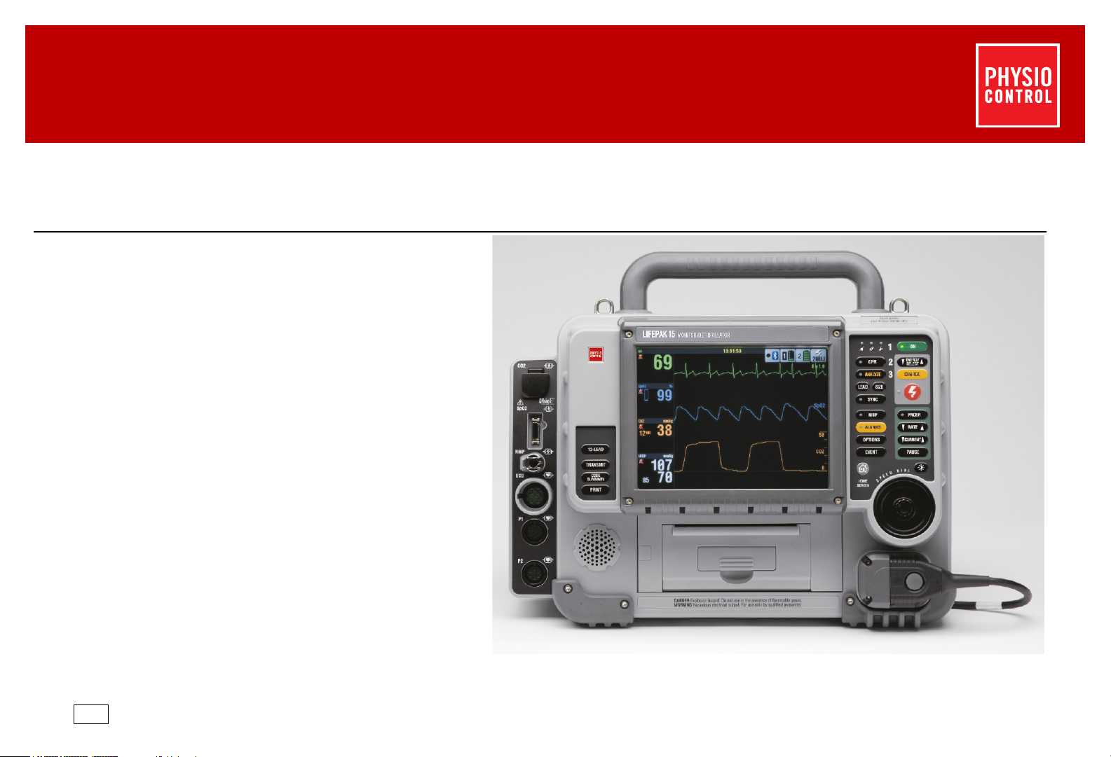
LIFEPAK 15 Monitor/Defibrillator
CO2
SpO2
NIBP
ECG
P1
P2
Area 1
Figure 3.2 (p. 56)
Area 2
Figure 3.3 (p. 60)
Device Description
Physical Description and Features
Service Manual
Front Panel
This section provides information about buttons, indicator LEDs, and connectors on the front panel. Select the area to view on
Figure 3.1 on p. 55
3
Section Menu Section Contents Back Index
Figure 3.1—Front panel
55
Page 56

LIFEPAK 15 Monitor/Defibrillator
ALARMS
OPTIONS
EVENT
HOME
SCREEN
ON
ENERGY
SELECT
CHARGE
CPR
SIZE
ANALYZE
LEAD
1
4
5
6
7
8
9
10
11
14
15
16
17
18
19
20
21
22
23
12
13
NIBP
PACER
RATE
CURRENT
PAUSE
SYNC
0
2
3
Service Manual
Click the appropriate number below to view a description of that feature. See area 2 in Figure 3.3 (p. 60).
Device Description
Physical Description and Features
3
Figure 3.2—Front panel area 1
Section Menu Section Contents Back Index
56
Page 57

LIFEPAK 15 Monitor/Defibrillator
CPR
ANALYZE
SIZE
LEAD
SYNC
NIBP
ALARMS
Service Manual
Table 3.1— Front Panel Area 1 Features
Number Description
Device Description
Physical Description and Features
3
0
1
2
3
4
5
6
7
8
9
VF dose label — Physio-Control recommended energy dose for adult
Ventricular Fibrillation (VF)
Service LED — Illuminates when service error codes are written into the Service Log (accessed in the Service/Status
menu, see Displaying the Service/Status Submenu (p. 226)). See Troubleshooting (p. 218) for information about error codes.
Battery charging indicator (V2 only) - LED illuminated when installed batteries are fully charged. LED flashes when either
battery is charging. LED is not illuminated when no batteries are installed or a battery is unable to be charged.
Auxiliary power indicator (V2 only) - LED illuminated when defibrillator is connected to auxiliary AC or DC power source, whether
defibrillator is turned on or off.
button and LED — Controls CPR metronome. LED is illuminated when metronome function is active.
button and LED — Activates the Shock Advisory System (SAS) in AED mode. The LED is illuminated when the SAS
is active and flashes when user is prompted to press
button — Changes ECG size.
button — Changes ECG lead or lead set.
button and LED — Activates synchronized cardioversion in Manual mode. The LED is illuminated when active.
When synchronized, the LED flashes with each detected QRS complex.
button (optional) — Initiates blood pressure measurement. LED is illuminated when BP measurement is being
obtained.
ANALYZE.
10
flashes when an alarm condition occurs.
button and LED — Open alarms menu or silences alarms. The LED is illuminated when alarms are enabled and
Section Menu Section Contents Back Index
57
Page 58

LIFEPAK 15 Monitor/Defibrillator
OPTIONS
EVENT
ON
ENERGY
SELECT
CHARGE
PACE R
RATE
CURRENT
Service Manual
Table 3.1— Front Panel Area 1 Features (Continued)
Number Description
Device Description
Physical Description and Features
3
11
12
13
14
15
16
17
18
19
button — Accesses optional functions. The options menu selections are: PATIENT, PACING, DATE/TIME, ALARM
VOLUME, ARCHIVES, PRINT, and USER TEST.
button — Accesses pre-defined and user-defined events.
HOME SCREEN button — Returns to Home Screen display or to previous menu.
button and LED — Turns device ON or OFF. LED illuminated when ON. Press and hold to turn device off.
button — Increase or decrease defibrillator energy level in Manual mode. Energy levels are from 2 joules to
360 joules.
button — Charges the defibrillator in Manual mode. QUIK-COMBO or hard paddles must be attached. When
operating with hard paddles, use the
button deactivates Pacing Mode and charges the device.
SHOCK button and LED — Initiates discharge of defibrillator energy in either AED mode or Manual mode. The LED
flashes when the device is fully charged. When operated with hard paddles, pressing both
discharge energy.
button and LED — Activates pacer function. LED illuminated when function is activated and flashes with each
current pulse.
button — Increases or decreases pacing rate. The up or down arrows on button adjusts the pacing rate in 10 ppm
increments, or rotate the
SPEED DIAL to change the rate in 5 ppm increments.
CHARGE button on the APEX paddle. If the device is in pacing mode, pressing this
SHOCK buttons on the paddles
20
10 mA increments, or rotate the
button — Increases or decreases pacing current. The up or down arrows on button adjusts the pacing current in
SPEED DIAL to change the current in 5 mA increments.
Section Menu Section Contents Back Index
58
Page 59

LIFEPAK 15 Monitor/Defibrillator
PAU SE
Service Manual
Table 3.1— Front Panel Area 1 Features (Continued)
Number Description
Device Description
Physical Description and Features
3
21
22
23
button — Temporarily slows pacing rate to 25% of the set rate. While pressed, PAUSED appears before PPM at
the bottom of the screen. Release to resume pacing at the set rate.
DISPLAY MODE button — Switches between color display and high contrast SunVue™ display.
SPEED DIAL — Scrolls through and selects screen or menu items.
Section Menu Section Contents Back Index
59
Page 60

LIFEPAK 15 Monitor/Defibrillator
CO2
SpO2
NIBP
ECG
P1
P2
1
2
3
4
5
12-LEAD
10
11
12
SUMMARY
TRANSMIT
CODE
PRINT
6
7
8
9
12-LEAD
CO2
SpO2
NIBP
ECG
P1
P2
5
Service Manual
Click the appropriate number to view a description of that feature.
Device Description
Physical Description and Features
3
Figure 3.3—Front panel area 2
Section Menu Section Contents Back Index
60
Page 61

LIFEPAK 15 Monitor/Defibrillator
12-LEAD
TRANSMIT
CODE
SUMMARY
PRINT
Service Manual
Table 3.2— Front Panel Area 2 Features
Number Description
Device Description
Physical Description and Features
3
1
2
3
4
5
6
7
8
9
10
CO2 FilterLine® set port (optional) — Intake port for the CO2 monitor, which continuously measures the amount of CO2 during
each breath and reports the amount present at the end of exhalation (CO2).
SpO2/SpCO/SpMet sensor cable port (optional) — Connection port for the pulse oximeter, which noninvasively checks the
saturation of oxygen, carboxyhemoglobin concentration, and methemoglobin concentration in arterial blood.
NIBP pneumatic tubing port (optional) — Port for connection to the blood pressure tubing which connects to the cuff. NIBP
measures the blood pressure of the adult or pediatric patient.
ECG cable port — Connection port for the electrically isolated ECG patient cable. Cable configurations include the 12-lead
cable with limb lead and precordial lead attachments, 5-wire, and 3-lead cables.
IP cable ports — P1 and P2 connection ports for invasive pressure cables, which invasively measure arterial blood pressures,
central venous pressure (CVP), or intracranial pressure.
Note: If device is configured for temperature monitoring, P1 and P2 are replaced by a single port labeled TEMP.
button (optional) — Initiates acquisition, analysis, storage, and printing of a 12-lead ECG report.
button — Initiates transmission of patient data to another location through direct connect serial, gateway, or
wireless connection.
button — Prints a summary of the current patient documentation, including vital signs and waveforms.
button — Prints a continuous ECG stripchart. Press again to stop printing.
Speaker — Projects device tones and voice prompts.
11
12
Printer — Prints displayed waveforms, CODE SUMMARY, and other reports.
Therapy cable receptacle — Connection point for QUIK-COMBO therapy cable and hard paddles.
Section Menu Section Contents Back Index
61
Page 62

LIFEPAK 15 Monitor/Defibrillator
2
1
1
2
3
7
5
6
8
9
10
4
Service Manual
Rear Panel
This section provides information about features on the rear panel.
Device Description
Physical Description and Features
3
Figure 3.4—Rear features diagram
Section Menu Section Contents Back Index
62
Page 63

LIFEPAK 15 Monitor/Defibrillator
Service Manual
Table 3.3— Rear Panel Features
Number Description
Device Description
Physical Description and Features
3
1
2
3
4
5
6
7
8
9
10
Hard paddle wells — Storage area for a set of hard paddles.
USB port cover — Protects USB port from the environment.
System connector — Connects device to a gateway or external computer
for transfer of patient reports. Also provides real-time ECG output.
Auxiliary connector — Connection port for an external power
adapter.
Battery compartments — Accommodate two removable Lithium-ion
batteries that provide power for the LIFEPAK 15 monitor/defibrillator.
Battery contacts — Transfer battery status information.
Battery pins — Two pins in each battery compartment transfer the
battery power.
CO2 exhaust port (optional) — Vents gasses from CO2 monitor.
Paddle retainers — Provide secure retention and quick removal of
paddles.
Paddle test contacts — Allow complete paddles defibrillation checks.
Section Menu Section Contents Back Index
63
Page 64

LIFEPAK 15 Monitor/Defibrillator
QUIK-COMBO
electrodes (2)
3-lead ECG
cable
QUIK-COMBO
therapy cable
operating
instructions
(2) rolls
printer paper
LIFEPAK 15 monitor/
defibrillator
(no picture)
Test Load — for use with QUIK-
COMBO therapy cable
Service Manual
What Is Shipped with a Basic Device
A basic device includes the components shown below.
Physical Description and Features
Device Description
3
Figure 3.5—Components of the basic device
Section Menu Section Contents Back Index
64
Page 65

LIFEPAK 15 Monitor/Defibrillator
Service Manual
Devices, Options, Supplies, and Accessories
The following table, provided for reference, summarizes optional configurations, supplies, and accessories that are available. For
up-to-date ordering information, contact your Physio-Control representative or order online at store.physio-control.com (U.S. only).
Table 3.4— LIFEPAK 15 Configurations
Item Description
LIFEPAK 15 monitor/defibrillator
Device Description
Devices, Options, Supplies, and Accessories
3
Basic device
• 3-lead ECG cable
• QUIK-COMBO therapy cable
• Two sets QUIK-COMBO electrodes
• Device operating instructions
• 2 rolls of 100-mm printer paper
Optional Features
SpO2 (only) Accessories:
• Masimo SET
®
Red™ or LNCS™ sensors
• Masimo SET Red patient cables
• Nellcor Oximax™ sensors with Masimo Red™ MNC patient cable
SpO2/SpCO/SpMet Accessories:
• Masimo SET Rainbow
CO2 Accessories:
®
sensors
• Airway adapter
• FilterLine
• CapnoLine
Section Menu Section Contents Back Index
®
®
65
Page 66

LIFEPAK 15 Monitor/Defibrillator
Device Description
Devices, Options, Supplies, and Accessories
Service Manual
Table 3.4— LIFEPAK 15 Configurations (Continued)
Item Description
NIBP Accessories:
• Reusable blood pressure cuff
• Disposable blood pressure cuff
• NIBP hose - coiled
Vital signs and ST trending Provides graphical plot trending of vital signs or ST measurement for up to 8 hours.
Invasive Pressure See the operating instructions for IP accessory specifications.
Temperature Accessories:
• Disposable temperature probes
• Temperature probe adapter cable
12-lead ECG Accessories:
• Main 4-wire cable
• 6-wire precordial lead attachment
3
Bluetooth Provides wireless communication to Physio-Control data management products
Optional Therapy Delivery
Hard paddles
(can be used instead of QUIK-COMBO
cable and electrodes for defibrillation or
sync cardioversion)
Pediatric paddles
(attach to hard paddles
Section Menu Section Contents Back Index
Pair
Two required
66
Page 67

LIFEPAK 15 Monitor/Defibrillator
Service Manual
Table 3.4— LIFEPAK 15 Configurations (Continued)
Item Description
Electrodes
Device Description
Devices, Options, Supplies, and Accessories
3
LIFE•PATCH ECG electrodes
(for monitoring only)
QUIK-COMBO multifunctional ECG
electrodes with EDGE System
Power Options
Batteries (two per device)
LIFEPAK 15 monitor/defibrillator Station
or Mobile Li-ion Battery Charger
REDI-CHARGE™ Li-ion Battery Charging
System
LIFEPAK 15 monitor/defibrillator AC
power adapter
LIFEPAK 15 monitor/defibrillator DC
power adapter
™
technology
Sets of 3 or 4
• Standard — one pair
• Radio transparent system (RTS) — one pair
• RTS, pediatric — one pair
• REDI-PAK™ preconnect system — one pair
• Rechargeable Lithium-ion (with fuel gauge)
• AC power cord (country/region specific)
• DC power cable (Mobile Charger only)
• Mounting bracket with 4 (8-32 x 0.5”) screws, 4 lock washers, and template
• LIFEPAK 15 Li-ion battery adapter tray
• AC power cord (country/region specific)
• AC power cord (country/region specific)
• Power adapter output cable
• Optional - output extension cable
• DC power cord (unterminated)
• Power adapter output cable
• Optional - output extension cable
Section Menu Section Contents Back Index
67
Page 68

LIFEPAK 15 Monitor/Defibrillator
Service Manual
Table 3.4— LIFEPAK 15 Configurations (Continued)
Item Description
Data Management and Communications
Device Description
Devices, Options, Supplies, and Accessories
3
Cables
PC software
Training and Testing Tools
Patient simulators
Testers
Technical Manuals
Operating instructions
Service manual
Carrying Bags
Carrying bags
• Device-to-PC serial interface cable (connects to serial port on a PC or other equipment)
• Device-to-PC USB interface cable (connects to USB connector on a PC or other equipment)
• Analog ECG output cable (used to monitor ECG waveforms on external equipment)
• CODE-STAT™ Reviewer, version 8.0 (minimum version required)
• DT EXPRESS
™
3.0 Data Transfer Software
• QUIK-COMBO, 3-lead
• QUIK-COMBO, 12-lead (used with 12-lead ECG feature)
• Defibrillation checker for hard paddles
• Test Load — for use with QUIK-COMBO therapy cable only
• Printed, one included per device
• CD-ROM
• Basic carrying bag system — device only (includes left and right bags) with shoulder strap
• Shoulder strap
• Rear bag — (screws into back of device)
• Paddle well bag
Section Menu Section Contents Back Index
68
Page 69

LIFEPAK 15 Monitor/Defibrillator
Service Manual
Table 3.4— LIFEPAK 15 Configurations (Continued)
Item Description
Supplies
Device Description
Devices, Options, Supplies, and Accessories
3
Printer paper
SIGNAGEL
®
• 100-mm printer paper — box of 2 rolls
electrode gel • Use with hard paddles
Section Menu Section Contents Back Index
69
Page 70

LIFEPAK 15 Monitor/Defibrillator
Service Manual
System Context Diagrams
Refer to this section to view diagrams of how the major parts of the system are connected. The diagrams include the following:
• Front of Device (p. 71)
• Device Communication (p. 73)
Device Description
System Context Diagrams
3
Section Menu Section Contents Back Index
70
Page 71

LIFEPAK 15 Monitor/Defibrillator
Invasive
Pressure (P1 & P2)
or Temperature (T1)
(see next page)
printer
paper
12-lead
ECG
cable
3-lead or 5-
wire
ECG cable
SpO2
cable
finger
sensor
main 4-wire
cable
precordial
lead
attachment
QUIK-COMBO
therapy cable
(QUIK-COMBO
electrodes)
hard paddles
CO2
tubing
NIBP
tubing
3-pack ECG
electrodes
Service Manual
Front of Device
The following diagrams illustrate how the device connects to external accessories.
System Context Diagrams
Device Description
3
Figure 3.6—Device connections with external equipment and accessories
Section Menu Section Contents Back Index
71
Page 72

LIFEPAK 15 Monitor/Defibrillator
P1 and P2
connection - OEM
invasive pressure
adapter cable
examples of OEM
invasive pressure
transducers
P2
Temperature or P1
Accessory cable -
Temperature adapter
cable
Measurement
Specialties 4400 Series
disposable temperature
probe
Service Manual
The following diagram illustrates how the device connects to invasive pressure or temperature equipment.
Device Description
System Context Diagrams
3
Figure 3.7—Device connection with invasive pressure or temperature equipment
Section Menu Section Contents Back Index
72
Page 73

LIFEPAK 15 Monitor/Defibrillator
Bluetooth radio is integrated onto
the Interface PCB
Service Manual
Device Communication
Device Description
System Context Diagrams
3
Figure 3.8—Device system connector
Section Menu Section Contents Back Index
73
Page 74

LIFEPAK 15 Monitor/Defibrillator
Device Description
Functional Descriptions
3
Service Manual
Functional Descriptions
The LIFEPAK 15 monitor/defibrillator (device) is a platform medical device capable of combining a variety of therapeutic and monitoring
features. In addition to manual defibrillation, semiautomatic defibrillation, and noninvasive pacing, the device offers optional oximetry, invasive
pressure, noninvasive blood pressure, CO2, 12-lead ECG, and temperature monitoring. A key feature of the device is its ability to be upgraded as
the needs of the customer change or as new features become available. This portable device is powered by two Lithium-ion batteries.
The functional descriptions that follow provide a basic understanding of the device design and assist the qualified service technician in
troubleshooting to the subassembly level. Troubleshooting below the subassembly level, outside the factory, is not recommended, nor is it within
the scope of this service manual to provide the detail necessary to support such repairs.
See the system block diagram (Figure 3.9 on p. 76) when necessary as you review the following functional descriptions.
• System PCB (A01) (p. 77)
• Power PCB (A03) (p. 79)
• Therapy PCB (A04) (p. 80)
• OEM PCB (A06) (p. 83)
• Contact PCB (A07) (p. 84)
• Backlight PCB (A08) (p. 84)
• Printer Control Keypad (A09)/Main Keypad (A10) (p. 84)
• LCD Assembly (A11) (p. 84)
• Printer Assembly (A12) (p. 84)
• Transfer Relay Assembly (A13) (p. 85)
• Inductive Resistor (A14) (p. 85)
• Energy Storage Capacitor (A15) (p. 85)
• SpO2/SpCO/SpMet Module (A16) (p. 85)
• Interconnect Bracket (A17) (p. 85)
• NIBP Module (A21) (p. 86)
• Biphasic Module (A22) (p. 86)
• CO2 Module (A23) (p. 86)
Section Menu Section Contents Back Index
74
Page 75

LIFEPAK 15 Monitor/Defibrillator
Service Manual
• ECG Connector Cable (W07) (p. 86)
• System Connector Cable (W08) (p. 86)
• Therapy Connector Cable (W11) (p. 87)
• Speed Dial Assembly (W15) (p. 87)
• Speaker Assembly (W17) (p. 87)
• SpO2 Connector Cable (W22) (p. 87)
• CO2 Inlet Connector Cable (W28) (p. 88)
• IP Connector Cable (W33) (p. 88)
• Temperature Connector Cable (W35) (p. 88)
Device Description
Functional Descriptions
3
Section Menu Section Contents Back Index
75
Page 76

LIFEPAK 15 Monitor/Defibrillator
Biphasic
Module (A22)
IP Connector
Cable (W33)
IP /
Temperature
front end
Power
switching
ON/OFF
control
Power
processor
Power
supplies
SpO2 Connector
Cable (W22)
SpO2/SpC O/
SpMet Module
(A16)
OEM PCB
(A06)
Transfer Relay
Assembly
(A13)
Dump relay
control
Transfer relay
control
QUIK-COMBO
leads-off
(impedance
Paddles/
QUIK-COMBO
ECG
Defibrillator
processor
Paddles/pacer
processor
Therapy
Connector
Cable (W11)
Batt #1
Contact PCB
(A07)
Batt #2
Noninvasive
pacemaker
Energy storage
capacitor
charger
Interconnect Bracket
(A17)
ECG front end
Printer
controller
Display
controller
LCD backlight
converter
ECG
Connector
Cable (W07)
Printer
Assembly
(A12)
LCD
Assembly
(A11)
Backlight PCB
(A08)
Printer Control
Keypad (A09)/
Printer Control
Keypad (A09)/
LED driver
Keypad row
driver
Combined
audio output
Real-time clock/
non-volatile RAM
(RTC/NVRAM)
System
connector
interface
Single-Board
Computer
(SBC)
Audio
amplifier
Speed Dial
Assembly
(W15)
Speaker
Assembly
(W17)
System
Connector
Cable (W08)
Keypad
column
receiver
Field-Programmable Gate Array
(FPGA) and Application-Specific
Integrated Circuit (ASIC)
CO2 Inlet
Connector Cable
(W28)
CO2 Module
(A23)
NIBP Module
(A21)
Temperature
Connector
Cable (W35)
System PCB (A01)
Power PCB (A03)
Interface PCB (A05)
Therapy PCB (A04)
Energy
Storage
Capacitor
(A15)
Auxiliary
Power
Connector
Cable
(W09)
Bluetooth
Radio
Service Manual
Device Description
Functional Descriptions
3
Figure 3.9—System block diagram
Section Menu Section Contents Back Index
76
Page 77

LIFEPAK 15 Monitor/Defibrillator
Service Manual
System PCB (A01)
The A01 System PCB integrates and controls all functions of the device. There are two primary components:
Single-Board Computer (SBC)
The single board computer (SBC) functions as the central processing unit (CPU) for intensive number-processing tasks.
Field-Programmable Gate Array (FPGA) and Application-Specific Integrated Circuit (ASIC)
The field-programmable gate array (FPGA) and application-specific integrated circuit (ASIC) operate as the interface
between the CPU and all other therapeutic, monitoring, data management, and display device subsystems.
The following items identify the major subsystems of the A01 System PCB and their basic functions.
Power supplies
The A01 System PCB uses SW_VB (switched battery voltage) from the A03 Power PCB (via the A04 Therapy PCB) to
originate six power supplies for use throughout the device as follows:
~ +1.5 V power for use on the FPGA.
~ +1.8 V power for use on the SBC.
~ +5 V logic power for use on the A01 System PCB within the DUART, RTC, ASIC, and audio subsystems, and the A04
Therapy PCB.
~ +3.3 V logic power for use on the A01 System PCB within the SBC and FPGA CPUs, DSP, main, and ASIC
subsystems.
~ ±12 V analog power for use on the A01 System PCB and A04 Therapy PCB.
~ +24 V power for use in the A01 System PCB printer subsystem.
Device Description
Functional Descriptions
3
ECG front end
The device simultaneously captures inputs from up to 10 independent patient-connected leads for use in the interpretive
12-lead algorithm and ECG waveform display. The ECG front end performs the functions of patient isolation, electrostatic
discharge and defibrillation protection, lead selection, baseline dc restore, bandwidth filtering, internal pacemaker
Section Menu Section Contents Back Index
77
Page 78

LIFEPAK 15 Monitor/Defibrillator
Service Manual
detection, and ECG sampling via analog-to-digital conversion (ADC). Results from the ADC process pass across the isolation
barrier to the A01 System PCB digital signal processor (DSP) for filtering and signal conditioning before being used by the
SBC CPU. ECG input is through the parameter bezel W07 ECG Connector Cable.
IP / Temperature front end
The invasive pressure (IP) circuitry processes the input signal from a disposable IP transducer through the IP input
connectors on the device parameter bezel. Two input connectors are provided for simultaneous monitoring of two IP
channels. The W33 Invasive Pressure Harness provides the connection from the parameter bezel to the A01 System PCB,
where the IP/temp preamplifier circuitry is located.
The IP/temp preamplifier is isolated from the AC power ground by the ECG preamplifier iso-barrier. The transducer drive
circuitry supplies a positive 2.5 V and a negative 2.5 V excitation voltage to the resistive bridge-type transducer. The output
signal from the transducer is conditioned by a low-pass filter at the input of an instrumentation amplifier, which amplifies
the signal approximately 400 times. The signal is then multiplexed to the A-D converter, digitized, and then sent serially
across the iso-barrier for DSP processing and display.
The temperature circuity processes the input signal from a disposable temperature probe through the external adapter cable.
The temperature adapter cable connects to the connector below the ECG connector on the parameter bezel. The W35
temperature connector cable provides the connection from the parameter bezel to the A01 System PCB.
Device Description
Functional Descriptions
3
Printer controller
The device uses a 100-mm thermal array printer. The A01 System PCB printer controller governs motor speed, adjusts print
strobe pulse width, senses paper presence and door closure, senses printhead temperature, and provides the data to be
printed. Printer fonts are stored in memory devices located on the A01 System PCB.
Real-time clock/non-volatile RAM (RTC/NVRAM)
The RTC/NVRAM maintains the date and time and provides storage for device user setups. The RTC/NVRAM is powered by a
lithium coin cell battery.
Section Menu Section Contents Back Index
78
Page 79

LIFEPAK 15 Monitor/Defibrillator
Service Manual
System connector interface
The device can be connected to external equipment for transmitting analog ECG signal output, data transmission, factory
test, Physio-Control field service data collection, and device configuration during field upgrade. Except for analog ECG
signals, all data communication at the system connector is at RS-232 levels.
The analog ECG signal output path consists of A01 System PCB components, including a digital-to-analog converter (DAC),
low-pass filter, and electrostatic discharge protection.
The digital communications output path consists of the following two components:
~ Dual universal asynchronous receiver/transmitter (DUART)
~ Level-shifter, used for converting device internal logic levels to RS-232 levels.
Display controller
Data for display on the device A11 LCD assembly originates from the A01 System PCB Display Controller made up of a
portion of the SBC and dedicated data driver/buffers. Screen fonts are stored in memory devices located on the A01 System
PCB.
Combined audio output
Originates from the A01 System PCB ASIC. System audio (voice prompts and alarm tones) from the ASIC returns to analog
form in an A01 System PCB DAC. System audio is filtered and routed to the A05 Interface PCB audio amplifier for
application to the W17 Speaker Assembly. Voice prompts are stored in memory devices located on the A01 System PCB.
Device Description
Functional Descriptions
3
Power PCB (A03)
The A03 Power PCB manages application of power to the device from the two Li-ion batteries. Additional functions include power
on/off control, “smart” battery communication, routing battery charge currents, battery voltage measurement, over-current
protection fusing, and serial communication of power status to the A01 System PCB.
A03 Power PCB operation centers around a power processor, which detects the presence of available power sources, selects a
power source for use by the device, and monitors their status (for example, low battery, replace battery, removal from the device,
etc.) and can apply charging currents from an attached power adapter to the batteries when connected.
Section Menu Section Contents Back Index
79
Page 80

LIFEPAK 15 Monitor/Defibrillator
Device Description
Functional Descriptions
Service Manual
When the device is OFF, closure of the device power control activates A03 Power PCB circuitry to alert the power processor, which
chooses the appropriate source to originate SW_VB (switched battery voltage) power. SW_VB is then routed, in turn, to the A04
Therapy PCB and A01 System PCB for use, as is, and for further processing into system power supply voltages.
Closure of the power control when the device is ON triggers an orderly device shutdown prior to turning off SW_VB.
Therapy PCB (A04)
The A04 Therapy PCB maintains the patient interface for therapeutic purposes. In addition to developing defibrillation and
noninvasive pacing energies, the A04 Therapy PCB ensures safe delivery of those energies, captures ECG paddles, and monitors
attachment of the QUIK-COMBO electrodes.
The major subsystems of the A04 Therapy PCB and their basic functions are as follows:
Defibrillator processor
The defibrillator processor manages the defibrillator energy storage and delivery functions using serial inputs from the A01
System PCB ASIC, hardware inputs from external paddles, and inputs from other A04 Therapy PCB circuitry. Status of the
defibrillator subsystem is reported serially to the A01 System PCB ASIC.
3
Energy storage capacitor charger (ESCC)
Under control of the defibrillator processor, the ESCC converts COM_VB (common battery voltage) to high voltage for
application to the energy storage capacitor. Circuitry within the ESCC performs comparisons between stored energy and
target energy to limit charging to the value selected by the user. Additional circuits compensate the ESCC for low battery
voltage, provide over-voltage protection, and send divided capacitor high voltages to separate safety monitoring and energy
display circuits.
Transfer relay control
To enable the transfer of defibrillation energy, the A04 Therapy PCB integrates control signals from the SHOCK button (or
external paddles’ SHOCK buttons), defibrillator processor, ESCC, and the A01 System PCB ASIC. The transfer relay will be
activated only to deliver energy to the defibrillation electrodes when all conditions are satisfied in each system component.
Section Menu Section Contents Back Index
80
Page 81

LIFEPAK 15 Monitor/Defibrillator
Service Manual
Dump relay control
A fail-safe system used to safely dissipate defibrillation energies from the energy storage capacitor under a number of
circumstances (for example, change of energy selection, power removal, pacing activation, and QUIK-COMBO leads-off).
With the exception of power removal, the dump relay control system functions under the control of the system and/or
defibrillator processors.
QUIK-COMBO leads-off (impedance sense/motion detection)
With the QUIK-COMBO electrodes applied and the device in AED mode, leads-off/motion detection circuits are active. Only
leads-off is active when device is in Manual mode and QUIK-COMBO electrodes applied.
For purposes of this discussion, consider the leads-off/motion detector and patient system as a simple voltage divider.
Leads-off/motion detection relies on two main characteristics:
~ Leads-off/motion detector output impedance is relatively high (greater than 125 k
~ Patient impedance is relatively low (typically less than 30 ).
To exploit these characteristics, the device injects an ac impedance drive signal through the QUIK-COMBO electrodes into
the relatively low patient impedance and monitors the voltage drop across the patient. Minute perturbations sensed in the
low-amplitude signal developed across the patient represent motion; gross changes in the sensed signal indicate electrode
disconnection.
Device Description
Functional Descriptions
3
Paddles/QUIK-COMBO ECG preamplifier
The ECG paddles/QUIK-COMBO ECG preamplifier perform the functions of patient isolation, electrostatic discharge and
defibrillation protection, baseline dc restore, bandwidth filtering, internal pacemaker detection, and ECG sampling through
analog-to-digital conversion (ADC). Results from the ADC process are fed to the paddles/pacer processor.
Section Menu Section Contents Back Index
81
Page 82

LIFEPAK 15 Monitor/Defibrillator
Device Description
Functional Descriptions
Service Manual
Paddles/pacer processor
The paddles/pacer processor controls all facets of noninvasive pacemaker operation and paddles ECG signal acquisition.
Inputs received serially from the A01 System PCB ASIC are translated into controls to enable noninvasive pacemaker
delivery of properly timed pacing impulses at the desired current. Analog ECG from the Paddles/QUIK-COMBO ECG
Preamplifier is processed for local use and for transfer across the isolation barrier to the A01 System PCB DSP and onto the
A01 System PCB ASIC.
Noninvasive pacemaker
The A04 Therapy PCB noninvasive pacemaker subsystem develops isolated, adjustable current, 20-millisecond (nominal),
trapezoidal transchest pacing impulses. Major components of the noninvasive pacemaker include the paddles/pacer
processor, isolated low- and high-voltage power supplies, safety monitors, output current, pulse width, and pulse shape
controls. Controls for, and status of, the noninvasive pacemaker pass serially between the paddles/pacer processor and the
A01 System PCB ASIC.
Interface PCB (A05)
The A05 Interface PCB is primarily a signal collector/distributor used to simplify the routing of cables between the front and rear
halves of the device. The majority of signals from the device rear half are consolidated into the W04 System PCB/Interface PCB
Cable and passed to the A05 Interface PCB for further distribution to front half components (for example, A09 Printer Control
Keypad, A10 Main Keypad, A11 LCD Assembly, and A12 Printer Assembly). The following active circuits reside on the A05
Interface PCB:
3
Audio amplifier
Combined audio output signals receive final amplification in the A05 Interface PCB Audio Amplifier prior to application to
the W17 Speaker Assembly.
Section Menu Section Contents Back Index
82
Page 83

LIFEPAK 15 Monitor/Defibrillator
Service Manual
LED driver
Most device LEDs (located on the A10 main keypad) receive their drive from a serial-to-parallel converter located on the A05
Interface PCB. The Service LED drive originates from the A01 System PCB ASIC. The CHARGE and Power ON LEDs receive
their drive from the A03 Power PCB Power Processor.
Keypad row driver
The A01 System PCB ASIC reads device control buttons using a row and column address scheme (that is, each button
resides at a unique row and column address). Data from the ASIC shifts serially into the A05 Interface PCB Keypad Row
Driver (a serial-to-parallel converter) for application to button rows in the A09 printer control keypad and A10 main keypad.
A button closure enables row drive for a unique button to be sensed at the keypad column receiver.
Keypad column receiver
The A01 System PCB ASIC reads button closures serially from the Interface keypad column receiver (a parallel-to-serial
converter). In practice, closure of a device button passes row drive for that button to one, and only one, column receiver
input.
LCD backlight converter
The A05 Interface PCB applies filtered SW_VB through a Boost Converter to apply a minimum of 9.6 V to the A08 Backlight
PCB when it receives an enable signal (LCD_BL_ON) from the A01 System PCB display controller. A separate backlight
power supply is mounted on a metal bracket in the front case.
Device Description
Functional Descriptions
3
Bluetooth Radio
Bluetooth radio is integrated onto the Interface PCB. You can transmit current and archived data from the LIFEPAK 15
device to the LIFENET® System or to post-event review products such as CODE-STAT™ or DT EXPRESS™ software.
OEM PCB (A06)
A PCB used to integrate monitoring modes supplied to Physio-Control by third parties, or original equipment manufacturers
(OEMs), into the device system architecture. The A06 OEM PCB provides isolated power supplies, safety isolation, transient
protection, and signal interface adapters to support hosted OEM modules.
Section Menu Section Contents Back Index
83
Page 84

LIFEPAK 15 Monitor/Defibrillator
Device Description
Functional Descriptions
Service Manual
Contact PCB (A07)
Interfaces the Li-ion battery edge connector with the device and provides I2C communication to and from the battery. In addition,
the device uses a battery pull signal to indicate when the battery is being removed.
Backlight PCB (A08)
A printed circuit board that contains the circuitry to light the A11 LCD assembly screen.
Printer Control Keypad (A09)/Main Keypad (A10)
Common device controls (those not available using the SPEED DIAL) are initiated through either the A09 printer control keypad or
the A10 main keypad. The number of buttons on these keypads varies, depending on the features installed in a specific device. All
buttons, with the exception of ON and SHOCK, are addressed by the user controls section of the A01 System PCB ASIC.
• The ON button remains separate from the addressed buttons because it is needed to activate and deactivate the device without
ASIC interaction. Closures of the ON button are applied to the A03 Power PCB On/Off control block.
• The SHOCK button remains separate from the addressed buttons as a matter of fail-safe design, thus preventing inappropriate
activation under conditions of loss of CPU control. Operator-initiated closures of the SHOCK button are applied in two places:
the A01 System PCB ASIC and the A04 Therapy PCB defibrillator processor. The ultimate shock decision rests with both the
ASIC and defibrillator processor agreeing to deliver defibrillation energy.
3
LCD Assembly (A11)
A backlit, 640 × 480 pixel, color LCD that displays the primary and secondary ECG waveforms and text messages.
Printer Assembly (A12)
The 100-mm printer is installed to support 12-lead ECG monitoring and printing of multiple displayed waveforms.
Section Menu Section Contents Back Index
84
Page 85

LIFEPAK 15 Monitor/Defibrillator
Device Description
Functional Descriptions
Service Manual
Transfer Relay Assembly (A13)
A high-voltage relay mounted in the rear case that routes current from the A15 Energy Storage Capacitor, by means of the A22
Biphasic Module, through the W11 Therapy Connector Cable to the patient. Activation of the A13 Transfer Relay is governed by the
A04 Therapy PCB Transfer Relay Control block.
Inductive Resistor (A14)
A resistor that conditions the energy storage capacitor output for the wave generator/regulator circuit on the A22 Biphasic Module.
Energy Storage Capacitor (A15)
A metallized film capacitor used for energy storage. The capacitance of the A15 Energy Storage Capacitor is calculated when you
perform the TCP – Defibrillator Calibration procedure (see TCP – Defibrillator Energy Calibration (p. 200)). The nominal value is
195 μF.
SpO2/SpCO/SpMet Module (A16)
3
An OEM oximetry module supplied by Masimo. The module performs all functions related to oxygen, carboxyhemoglobin and
methemoglobin saturation, including sensor drive. Measurement results pass serially by means of the A06 OEM PCB to the A01
System PCB ASIC for display.
Interconnect Bracket (A17)
A terminal assembly used to interconnect the A13 Transfer Relay Assembly, A22 Biphasic Module, and A15 Energy Storage
Capacitor. The bracket itself is strapped to the A15 Energy Storage Capacitor with a large cable tie.
Section Menu Section Contents Back Index
85
Page 86

LIFEPAK 15 Monitor/Defibrillator
Device Description
Functional Descriptions
Service Manual
NIBP Module (A21)
An OEM NIBP monitor supplied by CAS Medical Systems. This module performs blood pressure monitoring, determining systolic,
diastolic and mean pressures and pulse rate. Measurement results pass serially by means of the A06 OEM PCB to the A01 System
PCB ASIC for display. Readings may be taken one time or on a recurring interval.
Biphasic Module (A22)
The biphasic module generates the biphasic waveform. The energy from the A15 Storage Capacitor is shaped into the biphasic
waveform. The energy passes through the A14 Inductive Resistor and A13 Transfer Relay to the W11 Therapy Connector.
CO2 Module (A23)
An OEM capnometry module supplied by Oridion Medical Ltd. This module continuously monitors end-tidal carbon dioxide (CO2)
and respiratory rate. Measurement results pass serially by means of the A06 OEM PCB to the A01 System PCB ASIC for display.
ECG Connector Cable (W07)
3
A front panel connector port used for attaching a 3-lead, 5-wire, or 12-lead ECG cable. Signal processing takes place on the A01
System PCB ECG front end processing circuitry (see ECG front end (p. 77)).
System Connector Cable (W08)
A rear panel connector port used for the exchange of digital information with an external modem, personal computer, factory test
systems, or Physio-Control field service test systems. The system connector also supplies a real-time analog ECG signal for use in
basic central monitoring or telemetry systems.
Auxiliary Power Connector Cable (W09)
A rear panel access port used for connection of external power adapters.
Section Menu Section Contents Back Index
86
Page 87

LIFEPAK 15 Monitor/Defibrillator
Device Description
Functional Descriptions
Service Manual
Therapy Connector Cable (W11)
A patient connector port used for delivery of either defibrillation or pacing therapeutic energies. The therapy connector allows
attachment of all available electrode accessories, including QUIK-COMBO pacing/defibrillation/ECG electrodes, and adult hard
paddles with energy select and discharge control.
NOTE: Some therapeutic accessories such as pediatric or posterior paddle attachments connect to the device by means of the
accessories mentioned previously.
The LIFEPAK 15 monitor/defibrillator uses varying jumper configurations within attached accessories to determine the type of
accessory connected. Discriminator circuitry within the A04 Therapy PCB defibrillator processor subsystem decodes the accessory
jumper configurations.
Speed Dial Assembly (W15)
A rotary, optical pulse-code modulator used to navigate through and select specific items from the LIFEPAK 15 monitor/defibrillator
menu system. Detent points on the SPEED DIAL provide tactile feedback to the user. When the desired item has been highlighted
on the display, the user presses the SPEED DIAL to enter the selection. The SPEED DIAL forms part of the user controls and
indicators block. Pulses derived from the W15 speed dial assembly pass serially to the user controls portion of A01 System PCB
ASIC.
3
Speaker Assembly (W17)
Used to annunciate device warnings, alarms, tones and, in AED mode, voice prompts. Drive for the W17 Speaker Assembly
originates in the A01 System PCB combined audio output block. Final amplification occurs in the A05 Interface PCB audio
amplifier.
SpO2 Connector Cable (W22)
A front panel connector port on the parameter bezel used for attaching an SpO2 (oximeter) sensor.
Section Menu Section Contents Back Index
87
Page 88

LIFEPAK 15 Monitor/Defibrillator
Device Description
Functional Descriptions
Service Manual
CO2 Inlet Connector Cable (W28)
A front panel connector port used for attaching a CO2 FilterLine®. Signal processing takes place on the CO2 module.
IP Connector Cable (W33)
A front panel connector port used for attaching invasive pressure transducers.
Temperature Connector Cable (W35)
A front panel connector port used for attaching external temperature probes.
3
Section Menu Section Contents Back Index
88
Page 89

LIFEPAK 15 Monitor/Defibrillator
Modes of Operation
4
Service Manual
Modes of Operation
When the LIFEPAK 15 monitor/defibrillator is turned on, it is always in one of six modes of operation. See the following topics to learn more
about a particular mode.
• Manual Mode (p. 90)—for performing manual defibrillation, synchronized cardioversion, noninvasive pacing, and ECG and vital
sign monitoring.
• AED Mode (p. 91)—for automated ECG analysis and a prompted treatment protocol for patients in cardiac arrest.
• Setup Mode (p. 92)—for changing default settings of the operating functions. For additional information, see LIFEPAK 15
Monitor/Defibrillator Setup Options (MIN 3208011 for V1, or 3306226 for V2).
• Service Mode (p. 94)—for authorized personnel to perform diagnostic tests and calibrations.
• Demo Mode (p. 96)—for simulated waveforms and trend graphs for demonstration purposes.
• Archive Mode (p. 97)—for accessing stored patient information.
Contents
Section Menu
Back
Index
89
Page 90

LIFEPAK 15 Monitor/Defibrillator
Service Manual
Manual Mode
Entering Manual Mode
To enter Manual mode, turn on the device. The factory default settings allow direct access to Manual mode. This access can be
modified to require confirmation or a passcode, or can be restricted entirely.
To change Manual mode access:
1. Select MANUAL MODE in the Setup menu (see Setup Mode (p. 92)).
2. In the Setup/Manual Mode submenu, select MANUAL ACCESS.
Table 4.1— Mode Response Descriptions
Mode/Response When Turned On Response Description
Manual/Direct (default) Turn on in Manual; direct access between AED and Manual modes
AED/Direct Turn on in AED; direct access between AED and Manual modes
Modes of Operation
Manual Mode
4
AED/Confirm Once Turn on in AED; operator confirms Manual mode selection once
AED/Confirm Always Turn on in AED; operator confirms Manual mode selection every time
AED/Passcode Once Turn on in AED; operator enters Manual mode passcode once
AED/Passcode Always Turn on in AED; operator enters Manual mode passcode every time
AED/Restricted Turn on in AED; no access to Manual mode
Section Menu Section Contents Back Index
90
Page 91

LIFEPAK 15 Monitor/Defibrillator
Service Manual
AED Mode
About AED Mode and Entering AED Mode
Factory default settings allow the device to operate in Manual mode. If you want the device to operate in AED (automated external
defibrillator) mode when it is turned on, you must change several setup options in different menus. The Setup/AED Mode menu
allows you to change settings for the AED prompted protocol.
To set up the device to turn on in AED mode:
1. Select MANUAL MODE in the Setup menu (see Setup Mode (p. 92)).
2. In the Setup/Manual Mode submenu, select MANUAL ACCESS.
3. Select the desired AED/XXX option.
4. Press HOME SCREEN.
5. Select MONITORING and then select CHANNELS.
6. Select SET 1 and then select CHANNEL 1.
Modes of Operation
AED Mode
4
7. Select PADDLES.
8. Select PREVIOUS PAGE. Confirm that Set 1 appears as the Default Set.
Section Menu Section Contents Back Index
91
Page 92

LIFEPAK 15 Monitor/Defibrillator
Service Manual
Setup Mode
About Setup Mode
Setup mode allows you to change the factory default settings and define custom settings based on local medical protocols and
specific needs. Options include general characteristics, manual and AED mode operating characteristics, alarms setup,
transmission sites, time-of-day clock, and other options. There is also a factory reset option that resets the device to the factory
default settings, (except for transmission menu entries and the maintenance interval, which remain unchanged). When setup is
complete, turn off the device to save the settings. The next time the device is turned on, the operating defaults you selected are
active.
Preserving the Existing Setup Options
Print the existing device setup options by selecting Print Defaults from the Setup mode menu or store setup options using the
LIFEPAK Defibrillator Software Solutions Configuration Setup Tool before performing service.
NOTE: The LIFEPAK Defibrillator Software Solutions Configuration Setup Tool is a Windows®-based application designed to assist
you in managing the setup options in your LIFEPAK 15 monitor/defibrillator. You can download the tool from Physio-
Control.com.
Modes of Operation
Setup Mode
4
Section Menu Section Contents Back Index
92
Page 93

LIFEPAK 15 Monitor/Defibrillator
General...
Manual Mode...
AED Mode...
CPR Metronome...
Pacing...
Monitoring...
12-Lead...
Events...
Alarms...
Printer...
Transmission...
Clock...
Reset Defaults...
Print Defaults
Set Passcodes...
Service...
Setup
Enter Setup Mode passcode
Setup
Service Manual
Entering Setup Mode
To enter the Setup mode:
1. Press and hold OPTIONS and EVENT, and then turn the device
ON. Continue holding until the Setup mode passcode prompt
appears. The factory default passcode is 0000; the reserved
technician passcode is 5433.
2. To enter the passcode, rotate the SPEED DIAL to select a digit,
and then press the SPEED DIAL to continue. After the last digit
is entered, the Setup menu appears.
3. Rotate the SPEED DIAL to select a setup option, and then press
the SPEED DIAL to display the option submenu.
For more detailed information about Setup mode options, see LIFEPAK 15
Monitor/Defibrillator Setup Options (MIN 3208011 for V1, or 3206226
for V2).
Modes of Operation
Setup Mode
4
Section Menu Section Contents Back Index
93
Page 94

LIFEPAK 15 Monitor/Defibrillator
Service Manual
Service Mode
About Service Mode
Service mode functions allow qualified service personnel to:
• Perform device calibration routines:
~ Defibrillation calibration
~ Pacing calibration
~ Printer calibration
~ CO2 calibration
~ NIBP calibration
~ Temperature calibration
• Perform device tests:
~Buttons test
~ Pixels test
~ Printer test
~ Voice/Tone test
• View the device status registers:
~ Device Log status
~ Service Log status
~ Device Data status
~ Counters status
~ Clear Memory (clears data management memory)
• Set the Service mode passcode
• Set the maintenance prompt interval
Modes of Operation
Service Mode
4
Section Menu Section Contents Back Index
94
Page 95

LIFEPAK 15 Monitor/Defibrillator
Service Manual
Entering Service Mode
To enter the Service mode:
1. Enter the Setup Mode (see Setup Mode (p. 92))
2. Rotate the SPEED DIAL to select SERVICE in the Setup
menu, and then press the SPEED DIAL. The Service mode
passcode prompt appears. The factory default passcode is
0000; the reserved technician passcode is 5433.
3. To enter the passcode, rotate the SPEED DIAL to select a
digit, and then press the SPEED DIAL to continue. After the
last digit is entered, the Service menu appears.
4. Rotate the SPEED DIAL to select a service option, and then
press the SPEED DIAL to display the option overlay.
Calibration — See Test and Calibration Procedures (TCP) (p. 188).
Modes of Operation
Service Mode
4
Test s — See Performance Inspection Procedures (p. 98).
Status — See Troubleshooting (p. 218).
Set Passcode — Set a Service mode access passcode.
Maint Prompt — See Preventive Maintenance (p. 265).
Setup — Return to the Setup Home Screen.
Section Menu Section Contents Back Index
95
Page 96

LIFEPAK 15 Monitor/Defibrillator
Service Manual
Demo Mode
About Demo Mode
Demo mode allows you to practice or demonstrate the monitoring functions of the LIFEPAK 15 monitor/defibrillator, including:
• ECG lead selection
• SpO2
• SpCO
• SpMet
• CO2
• NIBP
• IP
• Temperature
• Trend graphs
• Alarms
• Events
Modes of Operation
Demo Mode
4
Entering Demo Mode
To enter Demo mode:
1. Remove all front panel cables from the device (therapy, ECG, etc.). You cannot enter Demo mode if any front panel cable is
attached.
2. Press and hold EVENT and HOME SCREEN, and then turn on the device. The Demo mode screen appears.
3. To exit Demo mode, turn the device off.
Section Menu Section Contents Back Index
96
Page 97

LIFEPAK 15 Monitor/Defibrillator
Service Manual
Archive Mode
About Archive Mode and Entering Archive Mode
Patient information is stored in Archive mode. When you enter Archive mode, patient monitoring ends and the current Patient
Record is saved and closed.
To enter Archive mode:
1. Turn on the device and press OPTIONS.
2. Select ARCHIVES, and then select YES.
NOTE: You may be required to enter a password to enter Archive mode.
3. Turn the device OFF to exit Archive mode.
Modes of Operation
Archive Mode
4
Section Menu Section Contents Back Index
97
Page 98

LIFEPAK 15 Monitor/Defibrillator
Performance Inspection Procedures
5
Service Manual
Performance Inspection Procedures
The Performance Inspection Procedures (PIP) are a set of manual test procedures used for an operational, closed-case evaluation of the
LIFEPAK 15 monitor/defibrillator. This section describes the test procedures you will perform to determine if the LIFEPAK 15 monitor/
defibrillator is operating within the required specifications. Investigate and correct any malfunctions or out-of-tolerance conditions detected
during the PIP.
The PIP comprises safety and performance tests recommended by AHA/ASHE (American Hospital Association/American Society for Hospital
Engineering) Maintenance Management for Medical Equipment and International Electrotechnical Commission (IEC) Technical Report 1288-2,
Maintenance of Cardiac Defibrillators-Monitors.
Perform the PIP as part of a regularly scheduled preventive maintenance routine. Also, perform the PIP after any repair, replacement, upgrade, or
any test and calibration procedure (see Test and Calibration Procedures (TCP) (p. 188)). The Performance Procedure Checklist (p. 647) is
provided as an optional tool for recording test results. For additional items, see the Operator’s Checklist found at the end of LIFEPAK 15
monitor/defibrillator Operating Instruction (MIN 3207184 for V1, or 3306222 for V2).
• PIP – Scope and Applicability (p. 100)
• PIP – Resource Requirements (p. 101)
• PIP – Test Equipment Requirements (p. 102)
• Manual Mode Access (p. 106)
• PIP – Device Preparation (p. 110)
• Power Management (p. 114)
• PIP – User Test and Date/Time Verification (p. 118)
• Miscellaneous Functions (p. 119)
~ PIP - Temperature Calibration Check Test (p. 119)
~ PIP – CO2 Tests (p. 123)
~ PIP – NIBP Tests (p. 129)
• PIP – Printer Tests (p. 133)
• PIP – Keypad Tests (p. 136)
Contents
Section Menu
Back
Index
98
Page 99

LIFEPAK 15 Monitor/Defibrillator
Service Manual
• PIP – Audio Test (p. 137)
• PIP – Invasive Pressure Verification - P1, P2 (p. 138)
• PIP – SpO2/SpCO/SpMet Test (p. 140)
• PIP – Recording Operating Data (Optional) (p. 141)
• PIP – ECG Performance Testing (p. 142)
• PIP – Defibrillator/Pacing Testing (p. 151)
• PIP – QUIK-COMBO ECG Characteristic Tests (p. 156)
• PIP – Standard Paddles User Test (p. 159)
• PIP – Standard Paddles Defibrillator Delivered Energy Tests (p. 161)
• PIP – Patient Impedance Test (p. 171)
• Data Management (p. 172)
• PIP – Leakage Current Tests (p. 177)
• PIP – Disabling/Resetting Maintenance Prompt (p. 187)
Performance Inspection Procedures
5
Contents
Section Menu
Back
Index
99
Page 100

LIFEPAK 15 Monitor/Defibrillator
Performance Inspection Procedures
PIP – Scope and Applicability
5
Service Manual
PIP – Scope and Applicability
The PIP applies to the LIFEPAK 15 monitor/defibrillator only. To complete the PIP, begin with the device preparation instructions (see PIP –
Device Preparation (p. 110)). All required PIP tests applicable to the device configuration under test must be performed.
See PIP – Resource Requirements (p. 101) for a listing of the necessary qualifications for PIP equipment, test equipment verification,
workstation power, and personnel.
See PIP – Test Equipment Requirements (p. 102) for a listing of test equipment, including specifications, required to complete the PIP.
Section Menu Section Contents Back Index
100
 Loading...