

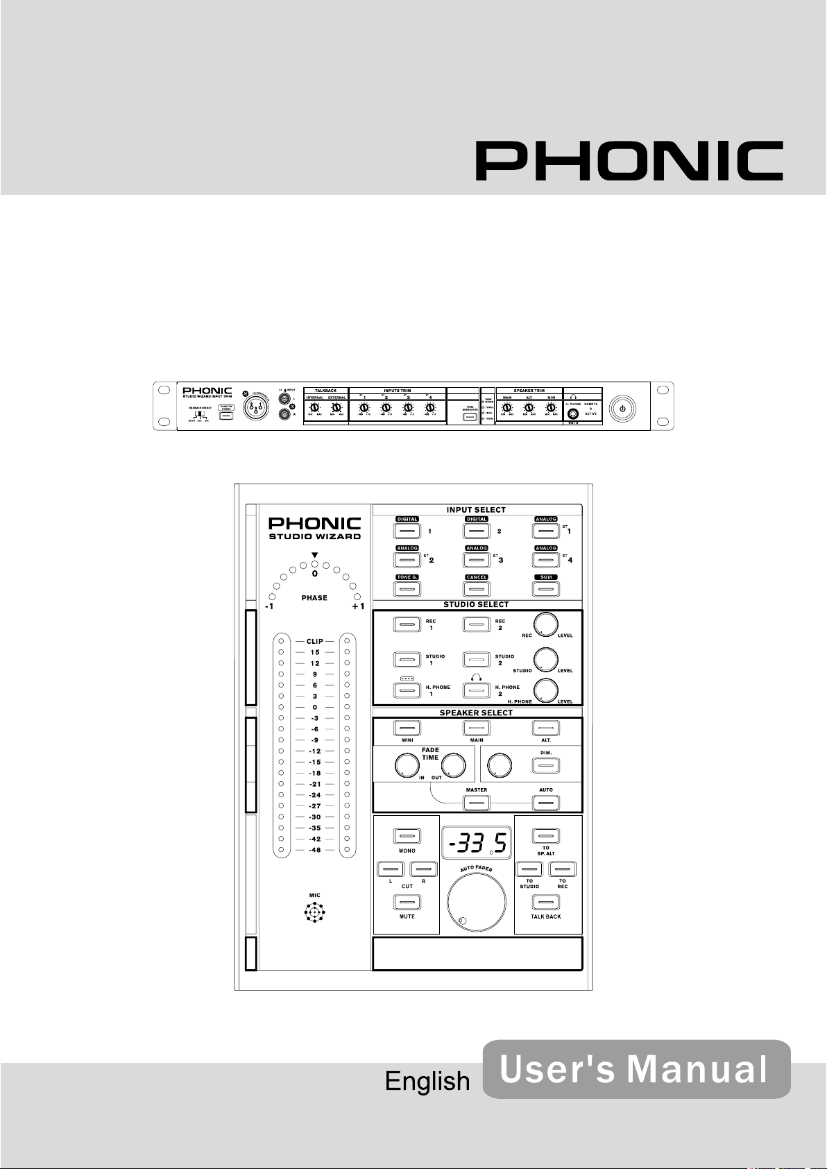
STUDIO WIZARD
Studio Monitor Controller
1. Re ad the se i ns tr uc ti on s be fo re o pe ra ti ng t hi s
apparatus.
2. Keep these instructions for future reference.
3. Heed all warnings to ensure safe operation.
4. Follow all instructions provided in this document.
5. Do not use this apparatus near water or in locations
where condensation may occur.
6. Clean only with dry cloth. Do not use aerosol or liquid
cleaners. Unplug this apparatus before cleaning.
7. Do not block any of the ventilation openings. Install
in accordance with the manufacturer’s instructions.
8. Do not install near any heat sources such as radiators,
heat registers, stoves, or other apparatus (including
.
9. Do not defeat the safety purpose of the polarized or
grounding-type plug. A polarized plug has two blades
with one wider than the other. A grounding type plug
has two blades and a third grounding prong. The wide
blade or the third prong is provided for your safety. If
the provided plug does not into your outlet, consult
an electrician for replacement of the obsolete outlet.
10. Protect the power cord from being walked on or
pinched particularly at plug, convenience receptacles,
and the point where they exit from the apparatus.
11. Only use attachments/accessories by the
manufacturer.
12. Use only with a cart, stand , tripod, bracket, or
table by the manufacturer, or sold with
the apparatus. When a cart is used, use caution
wh en m ov in g th e cart/apparatus
combination to avoid injury from tipover.
13. Unplug this apparatus during lighting
st or ms or when unused for lon g
periods of time.
14. Refer all servicing to service personnel.
Servicing is required when the apparatus has been
damaged in any way, such as power-supply cord or
plug is damaged, liquid has been spilled or objects
have fallen into the apparatus, the apparatus has
been exposed to rain or moisture, does not operate
normally, or has been dropped.
IMPORTANT SAFETY INSTRUCTIONS
CAUTION: TO REDUCE THE RISK OF ELECTRIC SHOCK,
DO NOT REMOVE COVER (OR BACK)
NO USER SERVICEABLE PARTS INSIDE
REFER SERVICING TO QUALIFIED PERSONNEL
The lightning flash with arrowhead symbol, within an
equilateral triangle, is intended to alert the user to the
presence of uninsulated “dangerous voltage” within the
product
’
magnitude to constitute a risk of electric shock to persons.
The exclamation point within an equilateral triangle is in-
tended to alert the user to the presence of important operat-
ing and maintenance (servicing) instructions in the literature
accompanying the appliance.
WARNING: To reduce the risk of or electric shock, do
not expose this apparatus to rain or moisture.
CAUTION: Use of controls or adjustments or performance
of procedures other than those may result in
hazardous radiation exposure.
The apparatus shall not be exposed to dripping or splashing and that no objects with liquids, such as vases,
shall be placed on the apparatus. The MAINS plug is used as the disconnect device, the disconnect device shall
remain readily operable.
Warning: the user shall not place this apparatus in the area during the operation so that the mains switch
can be easily accessible.
CAUTION
RISK OF ELECTRIC SHOCK
DO NOT OPEN

STUDIO WIZARD
Studio Monitor Controller
INTRODUCTION............................................................................................................................4
FEATURES........................................................................................................................................4
QUICK SETUP...............................................................................................................................5
Initial Setup..............................................................................................................................5
Level Setting............................................................................................................................5
Signal Routing.........................................................................................................................5
MAIN UNIT.....................................................................................................................................6
Front Panel..............................................................................................................................6
Rear Panel...............................................................................................................................7
REMOTE UNIT..............................................................................................................................8
Front Panel..............................................................................................................................9
TROUBLESHOOTING.................................................................................................................12
APPLICATIONS...........................................................................................................................13
SPECIFICATIONS.......................................................................................................................14
DIMENSIONS..............................................................................................................................16
BLOCK DIAGRAM....................................................................................................................17
Phonic preserves the right to improve or alter any information within this document without prior notice.
V1.4 FEB 05,2008

INTRODUCTION
FEATURES
Thank you for your purchase of the Phonic Studio Wizard, the perfect device for complementing
your DAW setup. The possibilities are endless
with the Studio Wizard, as you can accept multiple audio signals and send them to any number of destinations – all through the touch of a
few simple buttons. Digital or analog, the Studio
Wizard can accommodate any device, and will
unquestionably enhance your set up regardless
of your requirements.
This manual was designed to make your life a
whole lot easier. It is highly recommended that
you take a thorough read of it before attempting to operate the Studio Wizard. Doing so will
not only make you quite familiar with the Studio Wizard’s functions, but also help familiarize
yourself with the many dos and don’ts of the
product. After reading, store the manual in an
easy to access place for future reference – as
there will no doubt be something you missed the
rst time around.
Digital convenient routine volume control for
precise level adjustments
Switch amongst 3 sets of studio monitors
Built-in Talkback microphone for easy com-
munication with musicians
Talkback assignable to studio, record, or al-
ternative outputs.
Monitor 6 independent Stereo inputs includ-
ing one for your DAW Mix / broadcast / mastering
Six stereo inputs (2 digital and 4 analog)
Sum button allows multiple inputs to be con-
veniently selected and routed to outputs
Dual Headphone outputs with independent
volume controls and headphone mix bus
Automatic fade in and fade out for hands-
free fading
Tone generator: 100 Hz, 1 kHz, 10 kHz sine
waves and pink noise
Independent left and right cut buttons and
stereo to mono button
Microphone jacks for connecting external
microphones for talkback
High-end studio sound quality and robust
construction
Accurate dual 20-segment LED meter for
monitoring
Accurate 11-segment LED meter for phase
monitoring
Front panel headphone jacks with separate
volume control
All stereo outputs have independent input
sources
4 STUDIO WIZARD

QUICK SETUP
Initial Setup
1. Turn all power to the Studio Wizard off. To
fully ensure this, disconnect the AC cable.
2.
Connect the Studio Wizard remote unit to the
main unit using the supplied RJ-45 cable.
3.
Connect your desired inputs to the Analog
Inputs on the rear of the main unit.
4.
If you have any products with S/PDIF or
AES/EBU capabilities, you can connect the
product’s S/PDIF output to the Studio Wizard’s S/PDIF or AES inputs.
5.
Depending on your requirements, you may
wish to connect monitors to each of the Studio Wizard’s outputs, or you may wish to
connect an amplier and speakers; it’s really
up to you.
6.
Connect any suitable recording devices
(tape recorders, or even laptop computers)
to the Record outputs of the Studio Wizard.
7.
Plug the supplied AC power cable into the AC
power connector on the main unit, and the
other end into a suitable AC power source.
Level Setting
1. With all your inputs and outputs connected
to the Studio Wizard, turn the unit on.
2.
Turn the level control knobs in the Studio
Select section to the 0 position (indicated in
the numeric display).
3.
Send a signal into any of the 6 digital and
analog inputs (similar to the input that will
usually be fed into that input), and feed that
input through to the currently selected output
and speaker (check signal routing, if a problem occurs).
4.
Adjust the trim control of the corresponding input, on the front of the Studio Wizard’s
main unit, so that the signal level sits around
or slightly above the 0 mark on the remote
unit’s trim control.
5.
Now go and repeat the process with other
inputs. This should give you the best use of
audio from each input.
Signal Routing
1. Choose the output you wish to route any
signal to from the Studio Select area of the
remote unit. This could include the Record
1 and 2, Studio 1 and 2, and Head Phone
1 and 2 outputs. In this example, let’s say
you want to route the signal to the Record
1 outputs. Hold the Rec 1 button down for a
couple of seconds to enter Group Settings
Mode.
2.
The LEDs in the Input Select buttons sec-
tion should start ashing red. Press any of
these buttons to stop the LED ashing and
affectively remove it from your Group Setting.
3.
Press the Rec 1 button again to exit Group
Setting mode.
4.
In the Input Select section, the LEDs of the
inputs removed from your Group Setting
should be off. The others should be red,
with exception to the signal that is currently
sent to the Record 1 output, which should
be blue. You can push any of the other Input Select buttons with red LEDs to send
that signal instead, if you’d rather.
5.
To send all of the inputs from your Group
Setting to the Record 1 output, you can
now press the Sum button. All the red
LEDs should then turn blue, and all the corresponding signals should be routed to the
Record 1 output.
STUDIO WIZARD
5
Main Unit
The main unit of the Studio Wizard can be placed
in a typical audio rack with the rest of your gear
(ampliers, equalizers, etc). On this unit you will
nd all of the Studio Wizards inputs and outputs,
as well as trim controls ensuring that audio levels of the different inputs (and outputs) are not
excessive. In any permanent set up, you may
be able to plug your inputs and outputs into the
Studio Wizard’s main unit and leave it alone
from then on – all control over your audio can be
achieved through the remote unit.
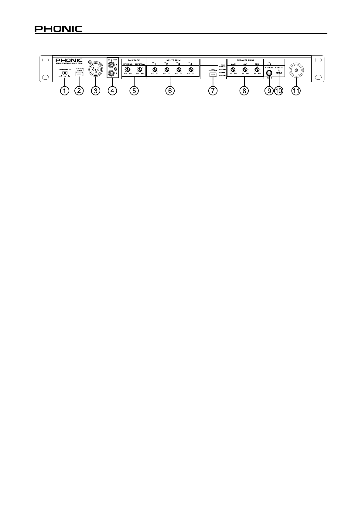
FRONT PANEL
1. Talkback Select Switch
This three-position switch allows users to select the built-in talkback microphone (or microphones) they most wish to use: the internal, the
external, or both – simultaneously.
The internal microphone is located on the tabletop remote controller, whereas the external can
be connected to the talkback mic input just to the
right of this switch.
2. Talkback Phantom Power Button
Press this button to activate +48VDC of phantom
power for the external talkback microphone connected to the Studio Wizard. Use phantom power when a condenser microphone (that requires
a +48V boost) is connected to the talkback microphone input. When phantom power is active,
the small LED inside the button lights up.
3. Talkback Microphone Input
This XLR-type input accepts balanced mic-level
signals from most dynamic and condenser microphones and is used it to connect an external
talkback microphone. Phantom power should be
activated when using condenser microphones.
4. Stereo 4 Inputs (RCA)
These RCA inputs accept unbalanced line-level
signals from CD players, tape decks and other
consumer audio devices.
5. Internal and External Talkback Controls
These two recessed trim level controls adjust the
gain level of the internal and external talkback
microphones.
6. Stereo Input Trim Controls
These recessed trim level controls adjust the
gain level of the four stereo analog inputs. Use
a small athead screwdriver or similar tool to adjust the levels. Turning these controls all the way
to the left will affectively mute the signal.
7. Tone Generator
The tone generator produces a continuous test
signal (tone) for use with real-time spectrum
analyzers when setting up the audio system.
Push the included button to toggle through the
test signals in the following order: 100 Hz 1
kHz 10 kHz Pink Noise. When a test tone
is active, it will be indicated by a small LED next
to the corresponding tone name. Push the Tone
Generator button on the remote unit to activate
the Tone Generator.
8. Speaker Trim Controls
These recessed trim level controls are used to
individually adjust the output level sent to each
set of speakers – the main, alternate, and mini.
HINT: Use a small athead screwdriver or even your nger-
nail to adjust the levels on recessed level controls.
9. Headphone Out 2
This 1/4" TRS output sends a stereo signal, ideal
for use with headphones when monitoring.
10. Remote Active Indicator
This LED indicator illuminates when the tabletop
remote control unit is connected.
11. Power Switch
This switch turns the power of the unit on and
off. When the unit is activated, the button will
illuminate blue.
6 STUDIO WIZARD

REAR PANEL
12. AC Power Connector
This is a standard IEC power cable receptacle.
Plug the power cable in here and connect the
other end of the cable to an appropriate AC power supply.
13. “To Remote" Connector
This RJ-45 jack allows users to connect the main
unit of the Studio Wizard to the remote desk-top
controller.
14. Digital Inputs (S/PDIF and AES)
These RCA and XLR inputs accept signals in S/
PDIF (RCA) or AES/EBU (XLR) format. Transfer rates are 24-bit, with sampling rates up to
192kHz (Mono).
15. Speaker Outputs
These three stereo 1/4" TRS outputs provide
balanced line-level signals for use with active
speakers/monitors or power ampliers driving
passive speakers. You can use the speaker trim
controls on the front panel to adjust the output
level.
17. Operating Level (Out) -10 dBV / +4 dBu
Use this switch to set the Record output 1 level
at -10 dBV, for use with semi-pro or consumer
level devices, or +4 dBu, for use with professional audio gear. Record output 2 is permanently
set to -10 dBV.
18. Head Phone Outputs
These 1/4" TRS outputs provide balanced linelevel signals ideal for use with headphone distri-
bution ampliers.
19. Studio Outputs
These 1/4" TRS outputs provide balanced linelevel signals for up to two studio recording devices.
20. Analog Inputs
These three sets of stereo 1/4" TRS inputs accept balanced line-level signals from up to three
devices.
16. Record Out 1 and 2
These stereo balanced 1/4" TRS and unbalanced RCA outputs provide line-level signals for
use with analog recording and dubbing equipment.
STUDIO WIZARD
7

Remote Unit
The Studio Wizard’s Remote Unit is where all the magic happens. With all the inputs and outputs made
else where (and out of your way), users are free to move this small unit around as they see t. You can
route your input signals to any number of possible outputs (record, studio, etc.), as well as to speakers
for monitoring within a booth or studio, and use many of the included functions such as auto fade (in and
out), and the dim switch, for when producers receive phone calls.
8 STUDIO WIZARD

Front Panel
Input Select Section
21. Digital 1 Button
Press this button to select the S/PDIF digital input on the main unit.
22. Digital 2 Button
Press this button to select the AES/EBU digital
input on the main unit.
23. Analog 1 Button
Press this button to select the ST 1 input on the
main unit.
24. Analog 2 Button
Press this button to select the ST 2 input on the
main unit.
25. Analog 3 Button
Press this button to select the ST 3 input on the
main unit.
26. Analog 4 Button
Press this button to select the ST 4 input on the
main unit.
27. Tone Generator Button
Press this button to activate the tone generator.
Press it again to turn off the tone generator. After
activating the tone generator, press the appropriate Studio Select buttons to send the test tone to
their corresponding outputs.
28. Cancel Button
Press this button to cancel current group settings. This can only be done when in “Group
Setting" mode.
Studio Select Section
30. Rec 1 and Rec 2 Buttons
Press either of these buttons to select the inputs
you wish to send to the Record 1 or 2 outputs on
the main unit. Hold either of these buttons down
to activate the Group Setting mode, where you
can select all of the Inputs you wish to associate
with that particular output.
31. Studio 1 and 2 Buttons
Press either of these buttons to select the inputs
you wish to send to the Studio 1 or 2 stereo outputs on the main unit. Hold either of these buttons down to activate the Group Setting mode,
where you can select all of the Inputs you wish
to associate with that particular output.
32. Head Phone 1 and 2 Buttons
Press either of these buttons to select the inputs
you wish to send to the Record 1 or 2 outputs on
the main unit. Hold either of these buttons down
to activate the Group Setting mode, where you
can select all of the Inputs you wish to associate
with that particular output.
33. Studio Out Level Controls
These knobs control the level of their corresponding outputs, which will be displayed in the
digital LED display. There are three level control knobs, one each for the Record, Studio and
Head Phone outputs. Pushing the control will allow users to toggle the use of the level control
between the Record, Studio and Head Phones
1 or 2 outputs.
29. Sum Button
When any of the Studio Select buttons is pressed,
the sum key will allow you to select all of the inputs from your Group Setting and send them to
the corresponding output.
STUDIO WIZARD
9

Speaker Select Section
34. Mini Button
Press this button to send the selected inputs to
the mini speaker output on the main unit.
42. Dim Button
Press this key to instantly attenuate the main
output level by the amount selected. It is highly
useful when receiving phone calls or communicating with the talent.
35. Main Button
Press this button to send the selected inputs to
the main speaker output on the main unit.
36. Alternative Button
Press this button to send the selected inputs to
the alternative speaker output on the main unit.
Fader
37. Fade In Time Control
Adjust this knob to set the fade in time.
38. Fade Out Time Control
Adjust this knob to set the fade out time.
39. Master Button
When the Master key is activated, the auto fader
only applies to the speaker (or monitor) outputs.
If the Master key is not activated then auto fading applies to all outputs.
40. Auto Button
Pressing this button automatically fades the selected signal, whether it be the speaker output
only or all outputs simultaneously.
41. Dim Level
This knob adjusts the amount of attenuation applied when the Dim button is pushed.
43. Mono Button
This button sums the stereo signal to mono to
check for phase cancellation.
44. Cut Left
This button cuts the output to the left channel
monitors.
45. Cut Right
This button cuts the output to the right channel
monitors.
46. Mute
This button mutes the audio to the Main speaker
output.
Talkback Section
47. To Alt. Speaker Button
Press this button once and release to route the
talkback microphone signal to the alternative
speaker outputs.
48. To Studio Button
Press this button once and release to route the
talkback microphone signal to both the Studio
and Headphone outputs.
10 STUDIO WIZARD

49. To Record Button
Press this button once and release to route the
talkback microphone signal to the REC outputs.
50. Talkback Button
After selecting the destination for the talkback
microphone signal, press and hold the Talkback
key to use the talkback microphone. Press the
button twice in quick succession to keep the talk
back on. Push once more to turn
the talk back off.
51. Talkback Microphone
This built-in condenser talkback
microphone has a sensitivity of
-42dB and a gain range of 15 dB
– 55 dB.
Main Section
52. Level Control Knob
This large rotary knob provides a precise analog
control for the monitor speaker output level. It is
accompanied by a digital display that gives an
exact level readout. This knob controls the level
only for those monitor speakers that are currently selected in the Speaker Select zone.
54. Phase Meter
This is an accurate 11-segment LED meter for
monitoring the phase of the monitor speaker outputs. When the meter’s illuminated LED indicator sits between the 0 and +1 mark, your signal
is in-phase. When the signal sits to the right of
the meter, the signal is out of phase, and should
be corrected. Please note that this phase meter
checks the phase of stereo signals only.
55. Output Level Meter
This is an accurate dual 20-segment meter for
monitoring the monitor speaker outputs.
53. Digital LED Display
This LED display provides a precise numeric
readout for all level control changes. The default
display is the monitor level control. When any
of the Studio Select, Fade Time or Dim Level
knobs are adjusted, changes will be displayed
on the LED panel. One to two seconds after level
changes have been made, the LED will return to
displaying the monitor level.
Rear Panel
56. RJ-45 Jack
This is an RJ-45 jack. The
cable that connects this unit
to the main unit is plugged
in here.
STUDIO WIZARD
11

TROUBLESHOOTING
No Power?
The obligatory ‘is it plugged in?’
Check the AC connection to see if there is,
in fact, power coming out of the socket.
Is the Power LED on? If so, check the ‘No
Sound’ section.
No Sound?
Is the power on? Check the LED indicator.
If the indicator remains dark, consult the
‘no power’ section of this troubleshooting
guide.
Ensure external devices are turned up high
enough for the signal to be clear through
the Studio Wizard.
If using active monitors for your output sig-
nal, ensure they are turned on and up.
Are all volume and trim controls turned to
an acceptable level?
Poor Sound?
Ensure all plugs are pushed into their ap-
propriate jacks all the way.
If the signal is distorted and loud, check
all input levels are set to a suitable level. If
any signal is turned up too high, the sound
quality can be terrible diminished.
Try listening to each of the input sources
one-by-one. If one or more of the sources
signal quality is poor, the Studio Wizard is
not the culprit in this case.
Try not to run cables over great distances,
and if possible use a high-quality cable.
Make sure your audio inputs and audio out-
puts are correctly selected. Incorrect routing may be of concern.
12 STUDIO WIZARD

APPLICATIONS
MICROPHONE
TURNTABLE
HEADPHONE
COMPUTER
SOUNDCARD
MIXER
HELIX BOARD 24 FIREWIRE
STUDIO WIZARD REMOTE UNIT
SUBWOOFER
ACTIVE
SPEAKERS
PHONIC P8A
ACTIVE
MONITORS
TAPE RECORDER
SPEAKER
AMPLIFIER
DAT RECORDER
HEADPHONES
STUDIO WIZARD
13

SPECIFICATIONS
Audio Inputs TRS1-4
Type 1/4" TRS Balanced & RCA-unbalanced
Input Impedance 2K Ω Balanced , 20K Ω unbalanced
Nominal Line level setting +4dBu(center detented)
Input level maximum +4 to +18dB unbalanced & Balanced
Trim Range -∞to +18dB variable
THD+N Less than .0005% (1KHz @ 0dBu)
Frequency Response 10Hz-50KHz, +/-0.5dB
S/PDIF
Types RCA 75Ω
AES/EBU
Types XLR transformer balanced
Audio Outputs
Monitor out
Type 1/4" TRS Balanced
Nominal Line level setting +4dBu
Trim Range -∞ to 18dB variable
Output level maximum +18dB
Dim switch Attenuation 20dB
Trim Range -40 to +4 dB
Output level maximum +18dB
Studio out 1-2&H.phone out 1
Type 1/4" TRS Balanced
Impedance 500Ω
THD+N Less than .0025%
Frequency Response 10Hz-50KHz, +/-0.5dB
Gain control Range -∞ to +18dB
Output level maximum +18dB
REC OUT 1
Type 1/4" TRS Balanced
Impedance 600Ω
THD+N Less than .003% (1KHz @ 0dBu)
Frequency Response 10Hz-30KHz, +/-0.5dB
Output level maximum +18dB
Gain control Range -∞ to +18dB
REC OUT 2
Type RCA-unbalanced
Impedance 60 Ω
Sample Rates Auto detect 24 bit,
44.1K, 48K, 96K, 192K(Mono)
Sample Rates Auto detect 24 bit,
44.1K, 48K, 96K, 192K(Mono)
14 STUDIO WIZARD

THD+N Less than .008% (1KHz @ 0dBu)
Frequency Response 10Hz-50KHz, +/-1dB
Output level maximum +4dB
Gain control Range -∞ to +4dB
H.phone out 2
Type 1/4" TRS Active Stereo
Maximum Output 420mW/channel @ 60 Ω load
THD+N .015% (150mW/channel @ 60 Ω load)
Frequency Response 10Hz-50KHz, +1dB
Noise oor
20 to 20kHz bandwidth @ 1KHz 0 dBu All input to output -90 dBu
Talkback EXT.
Dynamic Microphone Input
Type XLR Female Balanced
Input Impedance 2400 Ω
Sensitivity -72dB
Mic Preamp
Gain control range 0-50dB
Internal Microphone
Type Electric Condenser
Sensitivity -42dB
Gain range 15-55dB
Input Meters
Type 20 segment LED
Range -48dB to +15dB
Accuracy Better than .25dB
Frequency Range 10Hz-22KHz
Phase Meter
Type In-phase LED set for 0° to +180°
Out-of-phase LED set for181° to 360°
Display -1, -0.5, 0, +0.5, +1 stereo (13-segment LED)
Tone generator Sine wave @ 100Hz, 1kHz, 10kHz
Level 0 dB
Volume Display
Type 7 segment numeric LED Display
Remote connect RJ45
Power requirements
Main voltage ~100V to ~120 V AC,50~ 60 Hz
Fuse 100-120V AC: 1A, 200-240V AC:500 mA
Power consumption 30 Watts
Mains Connection Standard IEC Receptacle
STUDIO WIZARD
15

DIMENSIONS
482/19
195/7.7
44/1.7
* All measurements are shown in mm/inches.
16 STUDIO WIZARD

BLOCK DIAGRAM
dr
a
oB
reth
g
u
oD
ESI
ON
KNIP
,K
01,K1,0
0
1NIS
W
5
3
yl
ppu
S
re
w
oP
g
ni
hc
ti
wS
dra
o
B ETOMER
E
T
O
M
E
R
r
el
lo
rt
no
C
or
ci
M&
AH
AM
AY
E
LB
A
C T
E
N REHTE
2
D
T
S
L
R
R
R
3N
OM
L
2
LA
T
I
GID
L
R
3 g
ol
an
A
L
2
P
H
L
N
I
AG
2
N
OM
L
1
D
T
S
L
R
2
C
E
R
L
NIA
G
NIAG
1 golanA
L
1
LATIGID
L
NI
T
NI CIM
R
R
1
N
OM
L
2 go
l
anA
L
R
R
1PH
L
4 go
l
anA
L
NIA
G
NI
A
G
1C
E
R
L
NI
AG
NI TX
E CIM
R
NI
AG
R
R
R
R
R
STUDIO WIZARD
17

 Loading...