

Page 1

SMARTMAN 303A
SMARTMAN 703A
SMARTMAN 303A
User's Manual
Manual de Usuario
Page 2

English Español
SMARTMAN 303A
SMARTMAN 703A
ALL-IN-ONE INTELLIGENT AUDIO SYSTEMS
SISTEMAS INTELIGENTES DE AUDIO TODO-EN-UNO
ENGLISH........................................I
ESPAÑOL.......................................II
APPENDIX...........................................III
V1.0 08/21/2015
Page 3

USER'S MANUAL
CONTENTS
INTRODUCTION.................................................................1
FEATURES..............................................................................1
BASIC SETUP........................................................................1
SYSTEM OVERVIEW.............................................................3
SETTING.................................................................4
SPECIFICATIONS................................................................15
APPENDIX
DIMENSIONS......................................................................1
English
Phonic preserves the right to improve or alter any information within this
document without prior notice.
Page 4

The apparatus shall not be exposed to dripping or splashingand that no objects with liquids, such as vases,
shall be placed on the apparatus. The MAINS plug is used as thedisconnect device,the disconnect device shall
English
remain readily operable.
Warning: the user shall not place this apparatus in the area during theoperation so that the mains switch
can be easily accessible.
1. Read these instructions before operating this
apparatus.
2. Keep these instructions for future reference.
3. Heed all warnings to ensure safe operation.
4. Follow all instructions provided in this document.
5. Do not use this apparatus near water or in locations
where condensation may occur.
6. Clean only with dry cloth. Do not use aerosol or liquid
cleaners. Unplug this apparatus before cleaning.
7. Do not block any of the ventilation openings. Install
in accordance with the manufacturer
8. Do not install near any heat sources such as radiators,
heat registers, stoves, or other apparatus (including
9. Do not defeat the safety purpose of the polarized or
grounding-type plug. A polarized plug has two blades
with one wider than the other. A grounding type plug
has two blades and a third grounding prong. The wide
blade or the third prong is provided for your safety. If
the provided plug does not into your outlet, consult
an electrician for replacement of the obsolete outlet.
IMPORTANT SAFETY INSTRUCTIONS
CAUTION
RISK OF ELECTRIC SHOCK
DO NOT OPEN
CAUTION: TO REDUCE THE RISK OF ELECTRIC SHOCK,
DO NOT REMOVE COVER (OR BACK)
NO USER SERVICEABLE PARTS INSIDE
REFER SERVICING TO QUALIFIED PERSONNEL
The lightning flash with arrowhead symbol, within an
equilateral triangle, is intended to alert the user to the
’
s instructions.
.
WARNING: To reduce the risk of or electric shock, do
not expose this apparatus to rain or moisture.
presence of uninsulated
product
’
magnitude to constitute a risk of electric shock to persons.
The exclamation point within an equilateral triangle is in-
tended to alert the user to the presence of important operat-
ing and maintenance (servicing) instructions in the literature
accompanying the appliance.
“
dangerous voltage”within the
10. Protect the power cord from being walked on or
pinched particularly at plug, convenience receptacles,
and the point where they exit from the apparatus.
11. Only use attachments/accessories by the
manufacturer.
12. Use only with a cart, stand, t ripod, bracket, or
table by the manufacturer, or sold with
the apparatus. When a cart is used, use caution
when moving the cart/apparatus
combination to avoid injury from tipover.
13. Unplug this apparatus during lighting
storms or when unused for long
periods of time.
14. Refer all servicing to service personnel.
Servicing is required when the apparatus has been
damaged in any way, such as power-supply cord or
plug is damaged, liquid has been spilled or objects
have fallen into the apparatus, the apparatus has
been exposed to rain or moisture, does not operate
normally, or has been dropped.
CAUTION: Use of controls or
adjustments or performance
of procedures other than those may result in
hazardous radiation exposure.
Page 5

INTRODUCTION
Congratulations on your purchase of the Phonic
Smartman Intelligent All-In-One Audio Systems. These
systems incorporate everything one would expect to nd
in a typical front-of-house setup, but completely integrated
into a convenient, intelligent system. Complete with active
speaker, multi-channel mixers, wireless microphone
systems (sold separately) and extensive onboard signal
processing, the Smartman systems are fully-loaded with
everything you need for a live audio system.
Available in 3 different speaker congurations, the
Smartman 303A/703A features an 8” or 12” woofer
matched with just the right amount of power to provide
phenomenal sounds in any venue. The system expansion
options provide a means to extend the systems beyond
just a simple setup to a much more advanced, multispeaker setup.
We know how eager you are to get started – getting the
Smartman out and hooking up all your gear is probably
your number one priority right now – but before you do,
we strongly urge you to take a look through this manual.
Inside, you will nd important facts and gures on the set
up, use and applications of your brand new mixer. After
reading through the manual, please store it in a place
that is easy for you to nd, because chances are there’s
something you missed the rst time around.
FEATURES
4All-in-one system incorporates digital mixer, active
loudspeaker, two UHF microphones (optional) and
exible Windows software for remote operation
through RJ-45 connector (using an RS-485 protocol)
411 channel digital mixer including microphone combo
(XLR/¼") input, stereo line inputs and stereo RCA
inputs in addition to Bluetooth and USB inputs and the
UHF wireless microphone option
4Digital mixer includes level adjustment, exible
compressor/limiter, channel EQs, main GEQ, high
pass lters, low pass lters and delay
4Digital effect processor with reverb, tap delay, echo and
chorus effects, each with user-adjustable parameters
4Innite expansion through Smartman expansion
speakers (300A, 700A, 700D - sold separately)
4Flexible signal processing controlled through Windows
software or WiFi
4XLR and ¼" Link outputs with user-selectable stereo/
mono operation
4Wide frequency response for superior audio output
4Wireless UHF microphone systems (optional)
4Wireless Bluetooth audio streaming from smartdevices
BASIC SETUP
There are obviously many potential setup possibilities
for the Smartman system. Here we’re just going to go
through the basics to give you an idea of where to start.
1. First and foremost, make sure the Smartman is turned
off and unplugged before making any connections.
2. Once you ensure the Smartman is off, you can make
your input and output connections. Phonic suggests
using ribbon or dynamic microphones for the Mic
Inputs, instruments or CD players for line inputs, and
digital audio players on RCA inputs. For outputs, you
can connect Phonic Smartman Expansion Speakers
to the MAIN OUT connectors. Be sure to set the L/R
(stereo) and L+R (mono) to the position best for your
purposes.
3. Connect the Smartman’s Ethernet port to the Ethernet
port on your Windows-based system via the shipped
adapter.
4. Plug in the Smartman and turn on the power.
5. Open the Windows software and the control software
will establish the connection automatically.
6. Please set the input level you wish to use under the
“Input” page.
7. Preview the audio you will be sending into channel
1 of the Smartman system. Slowly turn up the
accompanying Gain control until you get the level
you’re after.
8. Repeat step 7 for further channels and inputs.
9. For the USB Recorder and Bluetooth streaming
functions, set the virtual software fader at the lowest
position and slowly increase it until you nd an
acceptable level. For Bluetooth streaming, the default
input level is 0 db. Please set Gain level knobs on the
rear panel to minimum and then set to the level you will
use.
CONTROLLING THE SOFTWARE
While the Smartman remote software on both Windows
PCs and the iPad is similar in appearance, the actual
control of the software may be different.
On the Windows software, virtual rotary controls are
adjusted using the mouse. The value of the control can
be increase and decrease by clicking left and right mouse
buttons respectively or by clicking and dragging to right
and left.
Virtual faders can simply be dragged up and down on
screen using the mouse.
Adjusting the rotary controls on the iPad is slightly
different. Push and hold the rotary control onscreen and
drag your nger up and down the screen to increase and
decrease the value.
English
1SMARTMAN 303A / SMARTMAN 703A
Page 6
English
10
9
1
8
7
11
2
3
12
13
14
6
5
4
16
15
17
18
2 SMARTMAN 303A / SMARTMAN 703A
Page 7

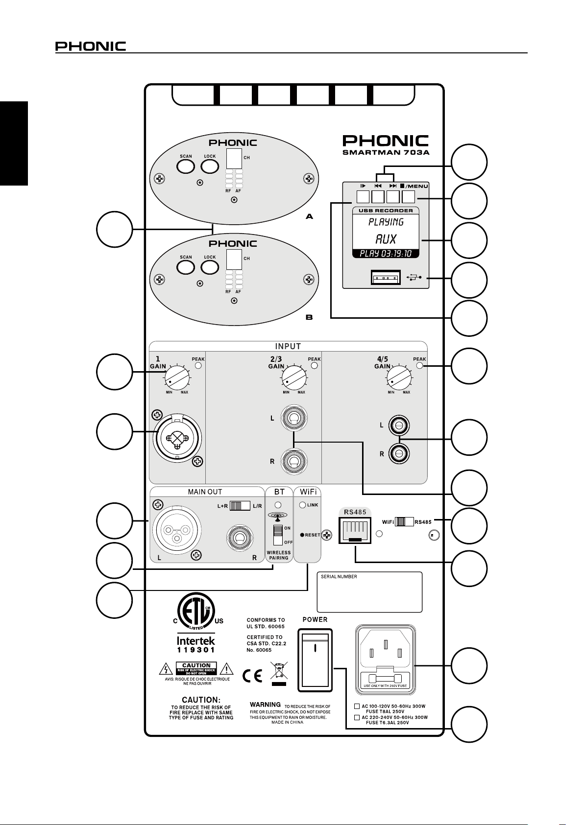
SYSTEM OVERVIEW
1. Wireless Microphone Modules (Sold Separately)
The Phonic WR-1 UHF wireless receivers can be installed
here. The Smartman speakers will feature a blank
faceplate which can be removed and replaced with the
UHF wireless receiver modules (sold separately). These
modules simply slide into the receiver slot and can be
screwed into place.
2. Gain Control
This control allows you to adjust the incoming signal from
their corresponding input jacks.
3. Combo Input Jack
This connector accepts both XLR and ¼” phone jack
connectors for either balanced or unbalanced connectors.
The incoming signal level can be adjusted using the
corresponding “Gain Control” (#2).
4. Stereo Input Connectors
These ¼” phone jacks are for the connection of stereo
input signals from such devices as mixers, keyboards,
etcetera.
5. RCA Input Connectors
These connectors are for unbalanced RCA connectors,
typically used on consumer products like CD and DVD
players.
6. Peak Indicator
The Peak indicator is found on each input channel. It
will light up when the input signal from the channel hits
high peaks that could potentially affect your audio. If this
occurs, Phonic suggests turning down the “Gain Control”
(#2) slightly.
7. USB Connector
Connect USB flash drives to this port. These drives can
contain mp3 or wma files for playback of digital audio.
Digital audio files can also be recorded directly to the USB
flash drive (in WAV/MP3 format).
8. USB Recorder Screen
This screen will display the current status of the
Smartman’s USB player. This could include information
on currently playing tracks (including track title, playtime,
etcetera). It is also used to view menus and options when
tracks are not playing.
9. Stop / Menu Button
This button has two main functions. The first is the stop
button, which obviously stops the currently playing track.
It also allows access to the USB player’s menus. By
pushing and holding this button for 2 seconds, you will
access the USB recorder’s menu where you will be able
to adjust settings such as repeat mode.
10. Forward / Reverse Buttons
These buttons can be used to skip back and forth between
audio tracks. Pushing and holding these buttons will allow
for fast forwarding/rewinding of the currently playing track.
11. Play Button
This button is used to play the currently selected track
on the USB player. When a track is currently playing, it is
also used as a pause button. In addition to this, the play
button acts as the “Enter” button when navigating menus.
12. Main Output
The main output of the Smartman features both XLR and
¼” phone jack outputs. The XLR output acts as the “left”
output and the ¼” connector acts as the “right”. These
are accompanied by a switch that selects output mode.
When “L+R” is selected, the left and right signals of the
Smartman will be combined and both of the Main Outputs
will essentially be mono outputs. When L/R is selected,
the Main Output will send the left and right output signals
accordingly.
13. Bluetooth Switch and Indicator
Use this switch to activate the Smartman’s BT streaming
option. When activated, you will be able to find the
Smartman in your phone or tablet’s Bluetooth menu as
an available device.
14. Wi-Fi Link & Reset
This little LED will illuminate when a connection is
successfully established between your iPad and the
Smartman system. Also included is a reset pinhole
button. To re-establish the connection between the two,
please pressing and holding this pinhole button for more
than 5 seconds.
For resetting the Smartman to the factory default, please
do as follow:
1. Turn off the power
2. Press and hold the reset pinhole button, and turn on the
power. The reset finishes as soon as all PEAK indicators
are off.
15. RJ-45 Connector (RS-485 Interface)
This little LED will illuminate when a connection is
successfully established between your iPad and the
Smartman system. Also included is a reset pinhole button.
16. Wi-Fi / RS-485 Selector
This switch is used to select the remote function you wish
to use. Set to Wi-Fi for wireless iPad operation and RS485
for use with the Windows desktop control software.
17. AC Power Connector
Connect the included AC power cable to this connector
and into a suitable power source allowing the unit to be
powered. This connector also contains the Smartman’s
fuse. If the fuse blows, please replace it with an identical
fuse.
18. Power Switch
This switch will turn the Smartman speaker on and off.
English
3SMARTMAN 303A / SMARTMAN 703A
Page 8

SETTING
The SETTING menu is found within the Windows software and iPad app (though the iPad features a slightly different
English
version). Within the Windows software, this menu features different options for your Wi-Fi Settings, RS485 Connection and
for loading and recalling Scenes.
4 SMARTMAN 303A / SMARTMAN 703A
Page 9
RS485 CONNECT
This section of the SETTING menu is used to establish
a connection between the computer and the Smartman.
The Smartman uses an RS485 protocol for all parameter
adjustments.
Connect: Once you’ve performed a search and found
your Smartman’s COM port, simply push the connect
button to establish a connection.
SCENE SETTING
Click “SAVE” to save your current settings to the
connected commuter as a “scene” and click “LOAD” to
import saved scenes from connected computer. Once the
Smartman is off, the current scene will be saved on the
Smartman locally.
iPAD CONNECTION
Through the free Smartman iPad app, your iPad will
become a wireless control surface for your Smartman
audio system. When using Wi-Fi, ensure to switch the
rear-panel switch to Wi-Fi. Then do the following to
establish a connection:
1. Go into your iPad’s Settings menu and enable Wi-Fi.
2. Select the SMARTMAN as your Wi-Fi source.
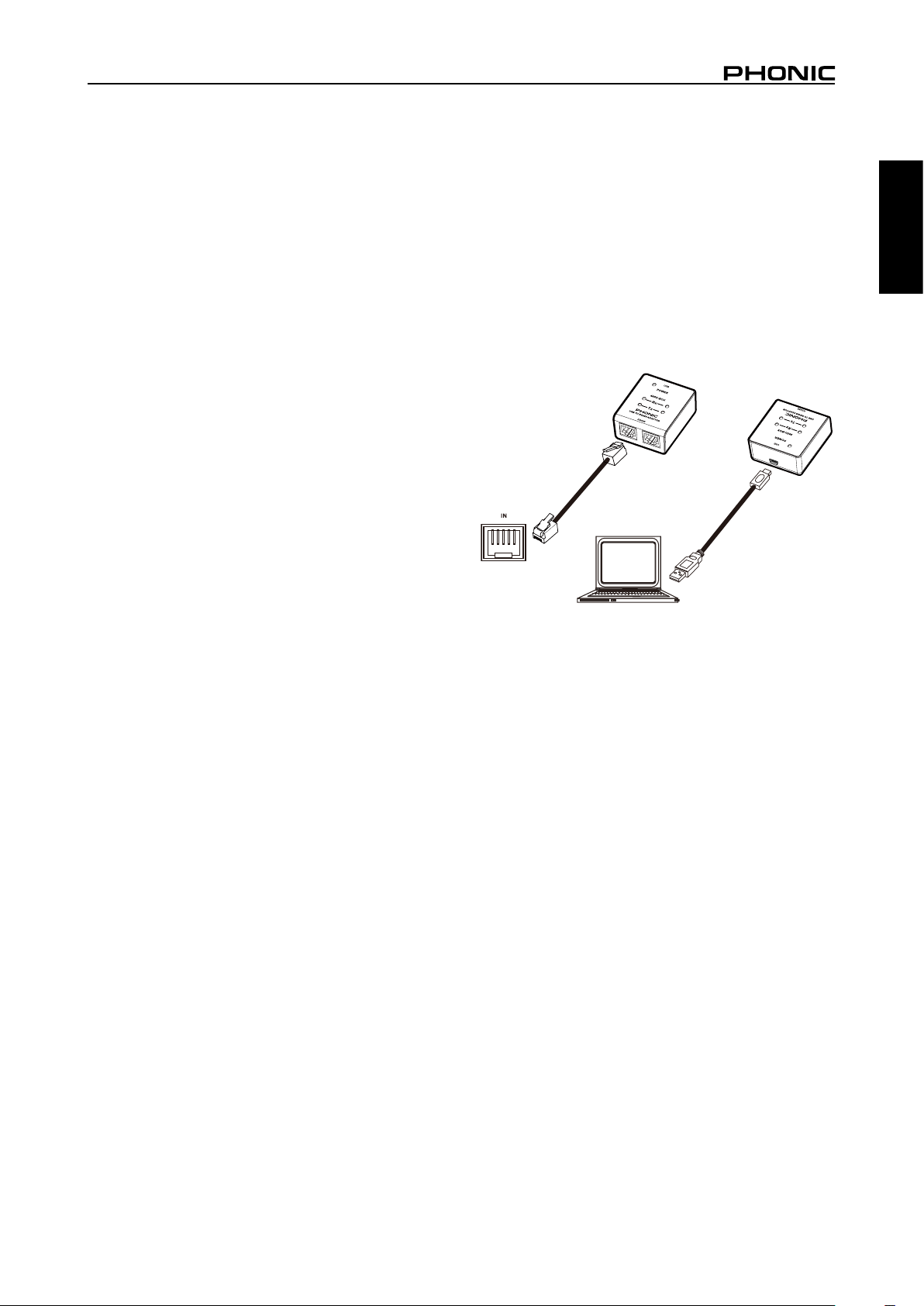
RS-485 CONNECTION
The Smartman offers direct control through Windows
control software via a typical Ethernet cable. The actual
control protocol is RS-485.
To use the Windows control software, the Smartman
system’s interface selection should be set to “RS-485”
instead of “Wi-Fi”.
1. Connect the Smartman with your Windows PC via the
shipped RS485 adapter with commercial Ethernet
cable and mini USB-to-standard USB cable. Ensure
that Smartman and your PC are turned on and ready
to go.
English
2. Open the Smartman Windows Control Software.
3. The control software will detect and make the
connection with the connected Smartman automatically.
5SMARTMAN 303A / SMARTMAN 703A
Page 10

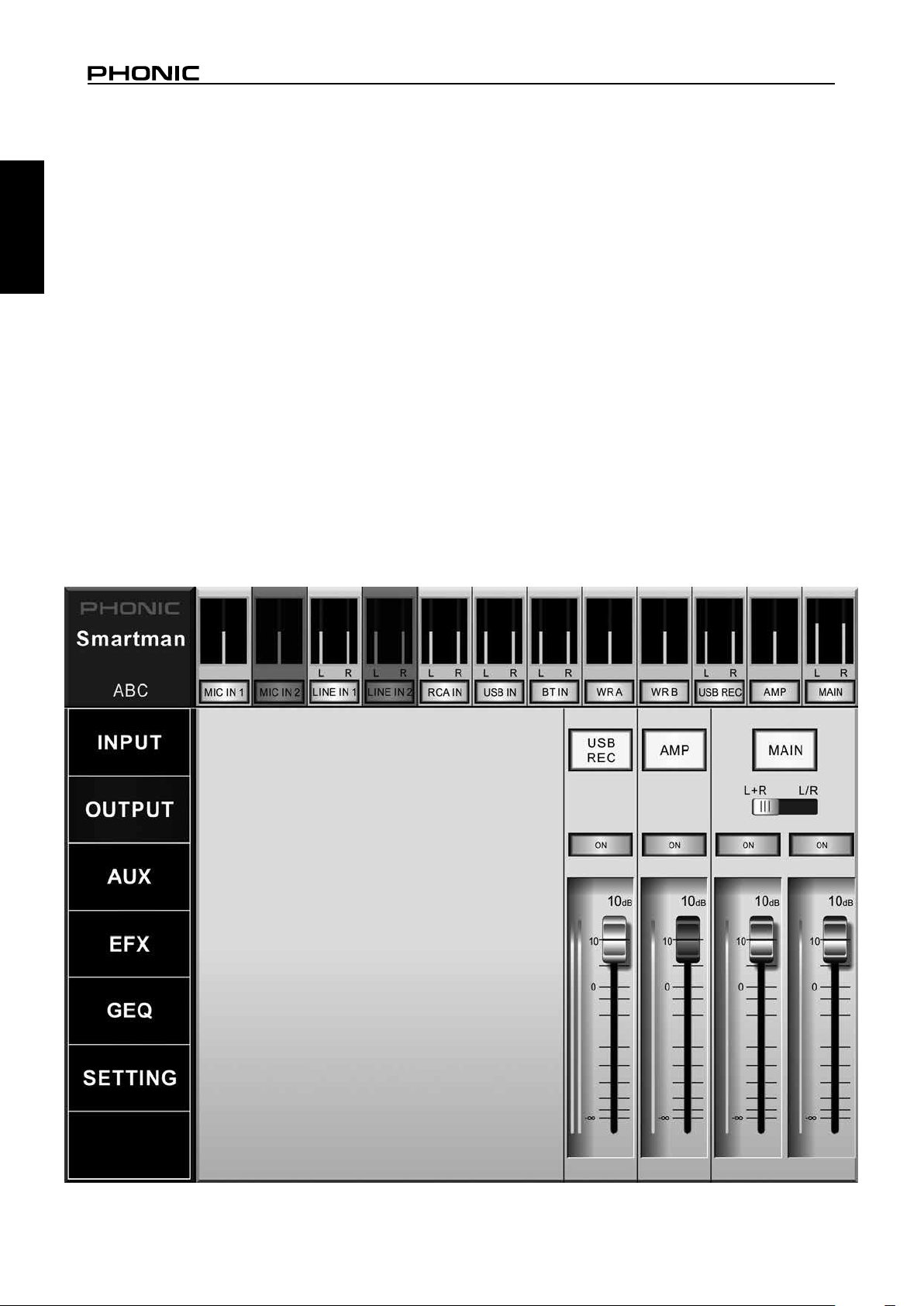
INPUT
The Input menu features a number of different settings
English
each of the individual inputs. These are all clearly labelled
on screen and include Mic In 1, Line In 1, RCA In, USB In,
BT In, WR A and WR B.
WR A and WR B inputs are only available upon installation
of the WR-1 wireless receiver modules.
Pan Control: This control adjusts the balance of the
incoming signal that the left and right channels will
receive. This is done by clicking the icon and dragging it
to the left or right.
On Button: This button simply turns the corresponding
channel on and off. When a channel is off, no audio will
be sent from that channel to the main mix.
Faders: These “virtual faders” are used to boost and cut
their corresponding channels’ audio signals. These faders
can be adjusted by simply clicking the fader and dragging
it up or down.
SIGNAL PROCESSORS
Each of the individual input mixes has its own page
featuring dedicated signal processors. These can be
accessed by simply selecting the corresponding button/
level meter found across the top of the software/app.
Please note that not every signal processor is found in
each and every input page.
High Pass Filter (HPF): A high pass filter essentially
removes all low-frequency audio below a selected
frequency. This is useful for removing stage rumble and
other low-frequency noise that can ruin an otherwise
perfect audio signal. The Smartman’s HPF can be
activated by pushing the appropriate button, and a
frequency selector is available. This feature is only
featured on microphone inputs.
Vocal Filter: The vocal filter is simply an enhancement for
vocal signals. Depending on the circumstances, the vocal
filter may or may not improve vocal tones. We suggest
auditioning the audio with the vocal filter on and off before
deciding whether or not to use it. Please note the vocal
filter is only featured on microphone inputs.
Talkover: The talkover button, featured only on Mic In 1,
allows for the microphone input signal to take precedent to
all over signals. When activated, the input for microphone
input 1 will override all other inputs on the main output.
6 SMARTMAN 303A / SMARTMAN 703A
Page 11

Tone Control: Every channel features a dedicated tone
control. These are 2- or 3-band equalizers that essentially
let you boost or cut your high, mid and low frequency
audio by 18 dB to sooth overly harsh audio or enhance
subtle sounds that need to be brought up in your mix
Microphone inputs feature a 3-band equalizer, with a
sweepable mid-frequency control. All other inputs feature
a 2-band EQ with high and low frequency controls.
Dynamic Processor: The Smartman has both
compressors and limiters built in. A compressor reduces
signals over a user-defined threshold by a user-defined
amount/ratio. A limiter is similar, but with a ∞:1 ratio.
On Button: This activates the Dynamic Processor.
Reset: The reset button will return the dynamic processor
to the default parameters.
Compressor Threshold: This adjusts the threshold of the
compressor. Once your signal level passes the selected
threshold, the compressor will kick-in at the set ratio.
Limiter Threshold: This adjusts the threshold of the
limiter function. This works in conjunction with the
compressor. A limiter simply act as a compressor with an
∞:1 ratio.
Ratio: This can be used to adjust the compressor input/
output signal ratio. This essentially determines the level
at which the signal will be cut after the threshold is
surpassed.
Output Gain: Increases the final output level of the
compressor/limiter.
Attack: The attack control adjusts the time it will take
for the compressor/limiter to kick in after the signal rises
above the set threshold.
Release: The release control adjusts the time it will take
for the compressor/limiter to deactivate after the signal
falls below the set threshold.
English
7SMARTMAN 303A / SMARTMAN 703A
Page 12
OUTPUT
The Smartman has two main outputs. The first is the “Amp”
English
output, consisting of all signals sent out through the speaker.
The second is the “Main” output, which is sent through the
line-level stereo outputs found on the rear of the Smartman.
In addition to these outputs, the Smartman offers the USB
Record output. As the name suggests, these signals are
sent directly to the USB Recorder.
The button at the top of each output strip can be touched
to enter into the individual signal processor pages. These
pages then have a “back” arrow on the top right-hand side
that will return you to the main Output page.
Main L+R or L/R Switch: While the Smartman has a
physical switch on the rear, the software also features a
switch that allows adjustment of the rear-panel outputs
between L+R and L/R. When set to L+R, the outputs will
essentially be mono. The left and right signals will be
combined and sent out of both the left and right outputs.
The L/R position means the left and right signals will be
separated and sent out their respective outputs.
On Button: The on buttons essentially allows the
corresponding output mix to be activated and deactivated.
Faders: Like the input mixes described on the previous
page, the output mixes each have their own “virtual
faders.”
SIGNAL PROCESSORS
Each of the output mixes has its own independent signal
processors. The Main output mix features a low-pass
filter (LPF), delay and dynamic function. The Amp output
features both delay and dynamics.
LPF: The low-pass filter found on the Main outputs
features an individual ‘ON’ button for each the left and
right output mixes. This will allow all low-frequency audio
to pass through while removing high frequency, making
the signal perfect for use with subwoofers. The frequency
control that accompanies the LPF on/off buttons allows
the cut-off frequency to be adjusted between 20 and
502Hz. Audio above the cut-off frequency is removed at a
rate of 12dB/octave.
Delay: The delay button allows users to activate a delay
on the currently selected output. Adding a delay to output
channels can help to compensate for distance between
speakers in large multi-speaker setups. A delay time of
one millisecond per foot (or 3 milliseconds per meter) that
the speaker is away from the stage is the general rule of
thumb in this application. This, however, is not always the
case. Thankfully, the Smartman allows the delay time to
be set in “meters’ or “feet” instead of “milliseconds”, taking
a lot of the guesswork out of the setup.
8 SMARTMAN 303A / SMARTMAN 703A
Page 13
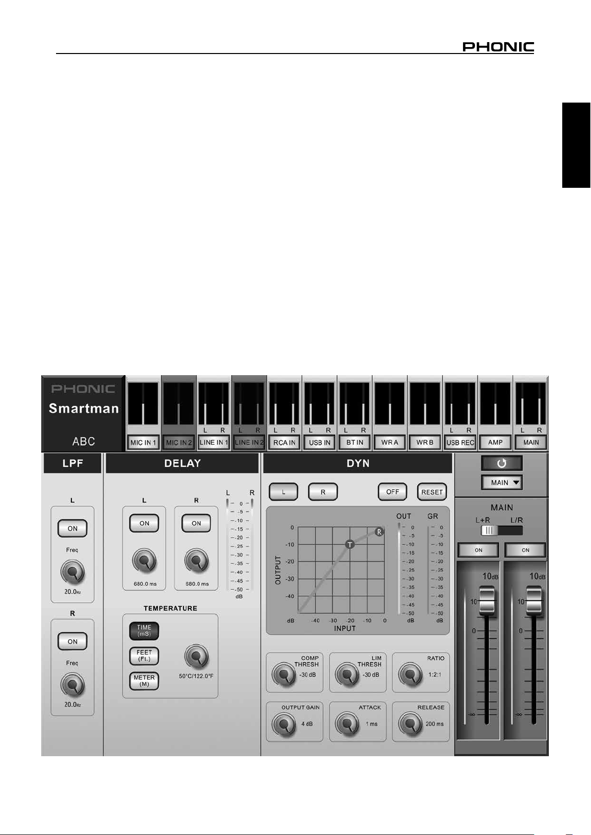
On Button: The on button quite simply activates the
output delay.
Time: These controls adjust the total delay time that
would be added to their respective outputs (left and right).
The delay time can be adjusted in milliseconds, meters
and feet.
Temperature: The temperature option allows the user to
set the ambient temperature of the current venue. This
allows the Smartman to calculate a more accurate delaytime when set in “feet” or “meters”.
In addition to the temperature control, this section of
the Delay function offers “time (ms)”, “feet” and “meter”
buttons, changing the adjustable delay between these
parameters.
Dynamics: The Smartman has both a compressor and
limiter available on the Main output mix. A compressor
reduces signals over a user-defined threshold by a user-
defined amount/ratio. A limiter is similar, but with a ∞:1
ratio.
On Button: This activates the Dynamic Processor.
Reset: The reset button will return the dynamic processor
to the default parameters.
L and R Buttons: These are found on the main output
mix and essentially determine whether the compressor /
limiter should be applied to the left and right output mixes.
Compressor Threshold: This adjusts the threshold of the
compressor. Once your signal level passes the selected
threshold, the compressor will kick-in at the set ratio.
Limiter Threshold: This adjusts the threshold of the
limiter function. This works in conjunction with the
compressor. A limiter simply act as a compressor with an
∞:1 ratio.
Ratio: This can be used to adjust the compressor input/
output signal ratio. This essentially determines the level
at which the signal will be cut after the threshold is
surpassed.
Output Gain: Increases the final output level of the
compressor/limiter.
Attack: The attack control adjusts the time it will take
for the compressor/limiter to kick in after the signal rises
above the set threshold.
Release: The release control adjusts the time it will take
for the compressor/limiter to deactivate after the signal
falls below the set threshold.
English
9SMARTMAN 303A / SMARTMAN 703A
Page 14
USB RECORD OUTPUT
The USB Recorder page has individual source buttons
English
that can be assigned to your USB Recording mix. These
include Mic 1, Line In 1, RCA input, BT (Bluetooth) input,
WR A and WR B (wireless receivers, if installed). Only
one source is allowed to be selected.
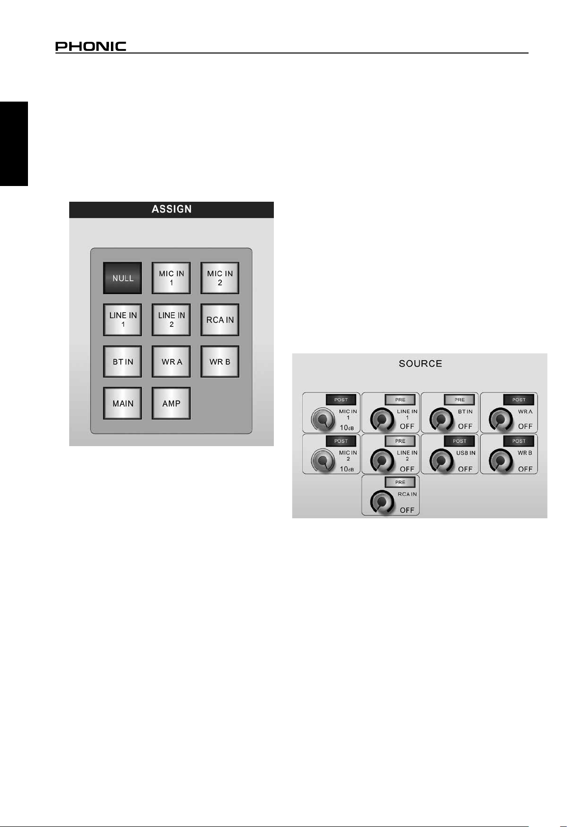
AUX MIX
The Smartman has a single AUX mix that users can create
using any of the input signals. The AUX mix is used as the
input source of the Digital Effects Processor, allowing use
of a number of input sources simultaneously. These can
then be fed into the Digital Effects Processor and sent out
the speaker (or through the left/right outputs).
To create the AUX mix, Phonic has provided a single
virtual rotary control for each of the incoming signals.
This includes Mic 1, Line 1, BT In, USB In, WR A, WR B
and RCA Input. It’s worth noting that WR A and WR B are
only functional when the wireless receiver modules are
installed.
When a virtual rotary control is turned all the way down, the
“AUX SEND” is essentially “OFF” for the corresponding
mix. These rotary controls can be adjusted up to 10dB.
Each AUX SEND also features a pre/post button. This
determines whether the signal sent to the AUX mix will
be taken before the corresponding channel’s fader (prefader) or after the signal has been altered by the channel’s
fader (post-fader).
10 SMARTMAN 303A / SMARTMAN 703A
Page 15
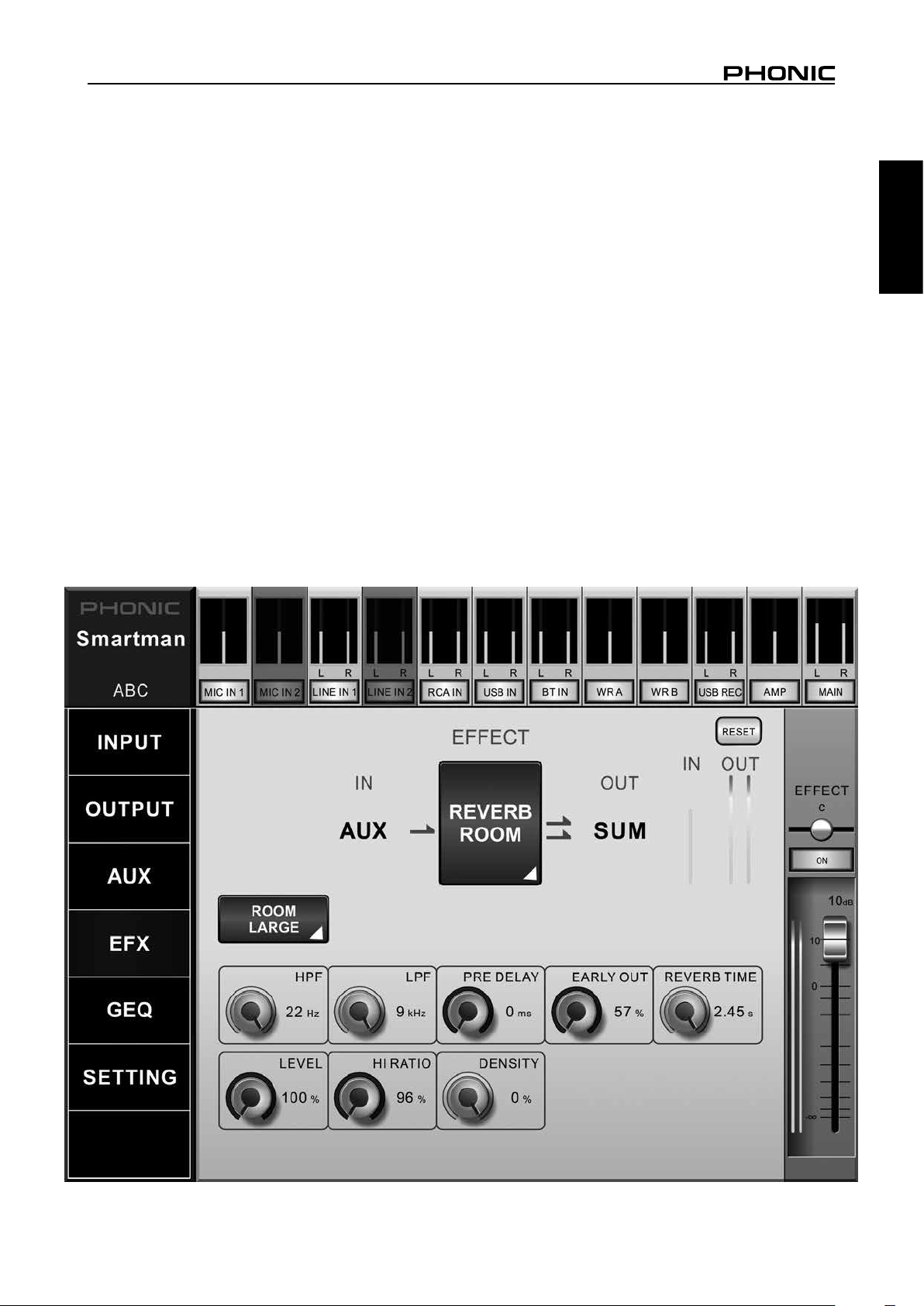
DIGITAL EFFECTS
The Smartman has a flexible digital effect processor
that provides a number of useful effects with numerous
user-adjustable parameters. The Smartman Digital Effect
Processor features a number of different Reverb effects,
an echo effect, tap delay, chorus effect and flanger effect.
In addition to this, the digital effect processor can be used
as a stereo 31-band graphic equalizer.
The input for the digital effect processor is taken from the
Smartman’s AUX mix. The AUX mix is made up of any
selection of the Smartman’s input sources, as selected
through the AUX mix menu. This is described in the “AUX
MIX” section of the manual.
The desired effect can be selected on screen in both
the iPad software and the Windows control software.
Touching the effect icon on screen will simply bring up the
pop-up menu and a new effect can be selected.
Reverb effects have up to 8 variations for each reverb
type. This means there are a total of 24 different reverb
effects found within the Smartman system. Each reverb
further has 10 user-adjustable parameters that can further
enhance the already flexible effects.
Each digital effect within the Digital Effect Processor has
its own user-adjustable parameters that vary depending
on the effect type. Please consult the Digital Effect
Table for detailed information on effect types and their
adjustable parameters.
The effect signal is processed and sent out through to
both the “Amp” mix (ie. the speaker) and the “Main” mix
(the left and right outputs).
The DFX processor’s reset button will restore all controls
to factory default positions.
As previously mentioned, a 31-band graphic equalizer
can also be selected in the effect menu. This is a stereo
GEQ that provides 12 dB of boost and cut to the available
frequencies. Available frequency bands are (in Hz) 20,
25, 31.5, 40, 50, 63, 80, 100, 160, 200, 250, 315, 400,
500, 630, 800, 1K, 1.25K, 1.6K, 2K, 2.5K, 3.15K, 4K, 5K,
8K, 10K, 12.5K, 16K and 20K.
English
11SMARTMAN 303A / SMARTMAN 703A
Page 16

GRAPHIC EQUALIZER
The Smartman offers a 7-band graphic equalizer. This
English
helps enhance your audio output sent both through the
Speaker (“Amp”) and stereo output connectors (“Main”).
This GEQ works independent of that featured on the Digital
Effect Processor. Both can be utilized simultaneously or
you can choose to use one or the other.
Each of the GEQ’s 7 bands allow 12 dB of cut or boost
to the available frequency bands. These bands are 63Hz,
150Hz, 350Hz, 1KHz, 2KHz, 6KHz and 12KHz. This gives
sufficient control of low, mid and high frequencies, however
fine control can be achieved by using the 31-band graphic
equalizer found in the Digital Effect Processor.
Your GEQ settings should be based on an analysis of
your room acoustics. The 303A/703A can be utilized to
better read room acoustics, although many professionals
play it by ear. To use the 303A/703A for this purpose, play
pink noise through the speakers and use the RTA function
to read the room’s response. After saving a few readings,
the 303A/703A’s equalizer calculator can be utilized to
give you the suggested curve of your graphic equalizer.
12 SMARTMAN 303A / SMARTMAN 703A
Page 17

TROUBLESHOOTING
The power won’t turn on
4 Is the power supply connected to the unit, and the AC-
end to an appropriate source?
4 Is the AC power outlet turned on?
4 Is the power switch turned on?
4 Check your Smartman’s fuse. This is located within the
AC connector, underneath the AC power Connector.
There is no output signal
4 Are the inputs turned on within the software?
4 Are the outputs turned on within the software?
4 Check input levels on both the Smartman’s rear panel
and within the software.
4 Check output levels within the software.
Sound is too soft
4 Are gain controls on the rear of the Smartman system
set to an adequate level?
4 Are input and output levels set adequately within the
software?
4 Are your input sources (analog mixers, keyboards,
etc) turned up to an adequate level?
4 Check the Dynamic processor settings on the input
and output mixes are not excessive.
4 If the issue is only related to external expansion
speakers, ensure you have not inadvertently activated
the low pass filter.
Sound is distorted
4 Check that gain settings, input and output settings are
not excessive.
4 Check the DFX menu to see if any effects are applied
to the AUX signal. If so, audition the system without
the DFX on to see if it improves the issue.
4 Could the EQ/DYN gain be set to an extremely high
setting?
English
13SMARTMAN 303A / SMARTMAN 703A
Page 18

DIGITAL EFFECTS
English
Effect
Reverb Room
(Large Room, Medium Room,
Small Room, Live Room,
Bright Room, Wood Room,
Heavy Room, Opera Room)
Reverb Hall
(Large Hall, Medium Hall,
Small Hall, Concert Hall, Dark
Hall, Wonder Hall, Jazz Hall,
Vocal Hall)
Reverb Plate
(Large Plate, Medium Plate,
Small Plate, Flat Plate, Light
Plate, Thin Plate, Perc Plate,
Industrial Plate)
Echo
Tap Delay
Chorus
Flanger
Parameter Range Description
H.P.F. 20 Hz to 20 kHz Adjusts the high pass lter cut off frequency
L.P.F. 20 Hz to 20 kHz Adjusts the low pass lter cut off frequency
Rev Time 50 ms to 10 sec Adjusts the reverb time of the effect
Pre Delay 0 to 100 ms Adds a delay prior to the effect being applied
Early Out 0 to 100% Adds a delay between early reections and the reverb
Hi Ratio 0 to 100% High frequency reverb ratio
Density 0 to 100% Reverb density
Level 0 to 100% Determines the level of reverb applied to the signal
Gate Threshold -70 to 0 dB Adjusts the gate threshold
Gate Hold Time 1 ms to 8 sec
Time L 0 to 640 ms Adjusts the delay time of left output
Time R 0 to 640 ms Adjusts the delay time of right output
Feedback 1 0 to 99% Feedback gain of input 1
Feedback 2 0 to 99% Feedback gain of input 2
FB HPF 20 Hz to 20 kHz Feedback High Pass Filter
FB LPF 20 Hz to 20 kHz Feedback Low Pass Filter
Feedback 0 to 99% Adjusts the feedback gain of input signal
Tap Button 1 ms to 5 sec Push twice to adjust the tap delay time
LPF 20 Hz to 20 kHz Adjusts the low pass lter frequency of the signal
HPF 20 Hz to 20 kHz Adjust the high pass lter frequency of the signal
L.F.O. 0.1 to 20 Hz Low frequency oscillation
Phase 0 to 180° Modulation phase adjustment
Mode Type Sine / Triangle Determines the modulation waveform
Depth 0 to 100% Chorus depth/density
Pre Delay 0 ms to 1 sec Early delay before the chorus effect begins
LPF 20 Hz to 20 kHz Low pass lter cut-off frequency
L.F.O. 0.1 to 20 Hz Low frequency oscillation
Phase 0 to 180° Modulation phase adjustment
Wave Sine / Triangle Determines the modulation waveform
Depth 0 to 100% Modulation depth
Pre Delay 0 ms to 1 sec Early delay before the anger effect begins
LPF 20 Hz to 20 kHz Determines the anger low pass lter cut-off frequency
FB 0 to 99% Determines the feedback gain of the anger effect
Adjusts the time the gate will hold after the threshold is
passed
Adjusts the time the gate will hold after the threshold is
passed
Adjusts the time the gate will hold after the threshold is
passed
14 SMARTMAN 303A / SMARTMAN 703A
Page 19

SPECIFICATIONS
SMARTMAN 303A SMARTMAN 703A
Amplifier Technology Class D
Power Output
Woofer 8" 12"
Tweeter 1" 1¾"
Frequency Response 50 Hz to 18 kHz 48 Hz to 20 kHz
Inputs
Output XLR, ¼" (selectable) XLR, ¼" (selectable)
Remote Operation WiFi / RJ-45 (RS-485) WiFi / RJ-45 (RS-485)
USB Playback / Recording Yes Yes
Bluetooth Yes Yes
Signal Processors
Digital EFX Reverb, Delay, Chorus Reverb, Delay, Chorus
Wireless Microphone Autoscan UHF (optional) Autoscan UHF (optional)
240 Watt Peak
120 Watt Continuous
1 x Combo (XLR/¼")
2 x ¼" TRS
2 x RCA
Compressor, Limiter, Delay,
Channel EQ, 7-band GEQ
Class D (Low Frequency)
Class AB (High Frequency)
1400 Watt Peak
700 Watt Continuous
2 x Combo (XLR/¼")
4 x ¼" TRS
2 x RCA
Compressor, Limiter, Delay,
Channel EQ, 7-band GEQ
English
Wireless Microphone Frequency
Indicators
Body Material Polymer Polymer
Handle Top 3 PU Handles
Dimensions (HxWxD)
Net Weight 9.5 kg (21 lbs) 19 kg (41.9 lbs)
Link On, Limit, Wireless 1 & 2, Bluetooth,
500 - 875 MHz
(region dependent)
Link On, Limit, Wireless 1 & 2, Bluetooth,
USB
418 x 292 x 252 mm
(16.5'' x 11.5'' x 9.9'')
500 - 875 MHz
(region dependent)
USB
635 x 375 x 372.5 mm
(25” x 14.8” x 14.7”)
15SMARTMAN 303A / SMARTMAN 703A
Page 20

English
SERVICE AND REPAIR
For replacement parts, service and repairs please contact the Phonic distributor in your
country. Phonic does not release service manuals to consumers, and advice users to not
attempt any self repairs, as doing so voids all warranties. Yo u can locate a dealer near you at
http://www.phonic.com/where/.
WARRANTY INFORMATION
Phonic stands behind every product we make with a no-hassles warranty. Warranty coverage
may be extended, depending on your region. Phonic Corporation warrants this product for a
minimum of one year from the original date of purchase against defects in material and
workmanship under use as instructed by the user’s manual. Phonic, at its option, shall repair
or replace the defective unit covered by this warranty. Please retain the dated sales receipt as
evidence of the date of purchase. You will need it for any warranty service. No returns or repairs
will be accepted without a proper RMA number (return merchandise authorization). In order to
keep this warranty in effect, the product must have been handled and used as prescribed in the
instructions accompanying this warranty. Any tampering of the product or attempts of self repair
voids all warranty. This warranty does not cover any damage due to accident, misuse, abuse,
or negligence. This warranty is valid only if the product was purchased new from an authorized
Phonic dealer/distributor. For complete warranty policy information, please visit
http://www.phonic.com/warranty/.
CUSTOMER SERVICE AND TECHNICAL SUPPORT
We encourage you to visit our online help at http://www.phonic.com/support/. There you can find
answers to frequently asked questions, tech tips, driver downloads, returns instruction and other
helpful information. We make every effort to answer your questions within one business day.
FCC Caution: To assure continued compliance, any changes or modifications not expressly
approved by the party responsible for compliance could void the user's authority to operate this
equipment. (Example - use only shielded interface cables when connecting to computer or
peripheral devices).
THIS DEVICE COMPLIES WITH PART 74 OF THE FCC RULES. This equipment complies with
FCC RF radiation exposure limits set forth for an uncontrolled environment.
support@phonic.com
http://www.phonic.com
Page 21

MANUAL DEL USUARIO
CONTENIDO
INTRODUCCIÓN........................................................................................1
CARACTERÍSTICAS...................................................................................1
CONFIGURACION BASICA..................................................................1
RESUMEN DEL SISTEMA......................................................3
AJUSTES.......................................................................4
ESPECIFICACIONES...............................................................................15
APÉNDICE
Español
DIMENSIONES.................................................................................1
Phonic se reserva el derecho de mejorar o alterar cualquier información
dentro de este documento, sin previo aviso.
9SMARTMAN 303A / SMARTMAN 703A
Page 22

Español
10 SMARTMAN 303A / SMARTMAN 703A
Page 23

INTRODUCCIÓN
Le damos la Enhorabuena por la compra, del sistema
de Audio inteligente de Phonic, Smartman. Este sistema
incorpora todo lo que un ingeniero esperaría encontrar,
en una instalación de audio típica; Todo su conjunto de
características, está completamente integrado, en un
sistema conveniente e inteligente. Con altavoz activo,
mezclador de múltiples canales, sistemas de micrófonos
inalámbricos (se vende por separado) y extenso
procesamiento de señales a bordo, los sistemas de
Smartman, están completamente equipado con todo lo
necesario, para una instalación de audio en vivo.
Disponible en 3 diferentes conguraciones de altavoces,
la Smartman 303A /703A, cuenta con un woofer de 8”, 10”
o 12”. Las 3 conguraciones, están emparejadas con la
exacta cantidad de potencia necesaria, para proporcionar
un sonido fenomenal en cualquier lugar. Las opciones de
expansión de este sistema, proporcionan un medio, para
extender una conguración sencilla, a una conguración
más avanzada de múltiples altavoces.
Sabemos que está impaciente por empezar - conseguir el
Smartman y conectar todo su equipo es probablemente
su prioridad número uno - pero antes de hacerlo,
le recomendamos que eche un vistazo a través de
este manual. En el interior, encontrará datos y cifras
importantes sobre la conguración, uso y aplicaciones
de su nueva mezcladora. Después de leer el manual, le
aconsejamos que lo guarde, en un lugar seguro, porque
lo más probable es que lo necesite para una futura
consultación.
CARACTERÍSTICAS
4Sistema Todo-en-uno; incorpora mezclador digital,
altavoz activo, dos micrófonos UHF (opcional) y un
software exible de Windows para una operación
remota a través de un conector RJ-45 (utilizando un
protocolo RS-485)
4Nuestro mezclador digital de 11 canales, incluye
una entrada combo de micrófono (XLR / ¼"),
entradas estéreo lineares y entradas estéreo RCA,
adicionalmente cuenta con Bluetooth y entradas USB
y una opción para micrófonos inalámbricos UHF
4Nuestro mezclador digital incluye ajustes de nivel,
compresor/limitador exible, ecualizadores de canal,
GEQ principal, ltros de paso alto, ltros de paso bajo
y la función de retraso “delay”.
4Procesador de efectos digital con reverb, delay tap,
efectos de eco y coro, cada uno con parámetros
ajustables por el usuario
4Expansión Innita través de los altavoces de
expansión Smartman (300A, 700A, 700D - se vende
por separado)
4Procesamiento de señal exible controlado a través
del software de Windows o WiFi
4Salidas de enlace XLR y ¼ ", con el funcionamiento
estéreo / mono seleccionable por el usuario
4Amplia respuesta de frecuencia para una salida de
audio superior
4Sistemas de micrófonos inalámbricos UHF (opcional)
4Streaming de audio inalámbrico con Bluetooth desde
dispositivos Smart
CONFIGURACION BASICA
Obviamente, hay muchas posibilidades de conguración
para el sistema Smartman. Aquí, sólo vamos a ir a través
los elementos de base, para que se pueda hacer una
idea por dónde empezar.
1. En primer lugar, asegúrese de que el Smartman esté
apagado y desenchufado antes de realizar cualquier
conexión.
2. Una vez que se ha asegurado que el Smartman
está apagado, usted puede hacer sus conexiones
de entrada y salida. Phonic sugiere el uso de cables
planos de conexión, o micrófonos dinámicos para
las entradas de micrófono, también sugerimos
instrumentos o reproductores de CD para entradas de
línea, y reproductores de audio digitales en entradas
RCA. Para las salidas, puede conectar el expansor
de altavoces Smartman de Phonic al MAIN OUT.
Asegúrese de ajustar el interruptor “L/R (estéreo)
y el L+R (mono)” a la posición adecuada para sus
propósitos.
3. Conecte el puerto Ethernet del Smartman, al puerto
Ethernet de su sistema Windows utilizando el
adaptador incluido.
4. Enchufe el Smartman y conectar la alimentación.
5. Abriendo el software de Windows y el software de
control establecerá la conexión automáticamente .
6. Vaya al menú “Input/Entrada” y establecer todos los
faders a la posición 0. Ajuste todos los controles de
ganancia/Gain en el Smartman a la posición más baja
(hasta el nal a la izquierda). También debe activar
todos los canales que desea utilizar.
7. Póngase en Vista previa (Preview), para monitorear
el audio que está enviando en el canal 1 del sistema
Smartman. Lentamente suba el control de ganancia/
Gain hasta llegar al nivel que está buscando.
8. Repita el paso 7 para más canales y entradas.
9. Para la Grabadora USB y funciones de streaming
Bluetooth, ajuste el fader virtual del software en la
posición más baja y aumentarla lentamente hasta
encontrar un nivel aceptable. Para la transmisión de
Bluetooth; también recuerde revisar ajustes de nivel
del dispositivo remoto, si usted encuentra problemas
para conseguir un nivel de señal razonable desde el
dispositivo.
CONTROL DEL SOFTWARE
While the Smartman remote software on both Windows
PCs and the iPad is similar in appearance, the actual
control of the software may be different.
On the Windows software, virtual rotary controls are
adjusted using the mouse. The left and right mouse
buttons are used to increase and decrease the value of
the control, respectively. For example, if you wanted to
lower the value of a control, you would then hover over
the rotary control on screen and push the left button.
Virtual faders can simply be dragged up and down on
screen using the mouse.
Adjusting the rotary controls on the iPad is slightly
different. Push and hold the rotary control onscreen and
drag your nger up and down the screen to increase and
decrease the value.
Español
1SMARTMAN 303A / SMARTMAN 703A
Page 24

Español
18
10
9
1
8
7
11
2
3
12
13
14
6
5
4
16
15
17
2 SMARTMAN 303A / SMARTMAN 703A
Page 25

RESUMEN DEL SISTEMA
1. Micrófono Inalámbrico (se vende por separado)
Los receptores inalámbricos de Phonic WR-1 UHF
pueden conectarse aquí. Los altavoces Smartman
estarán equipados con una placa de recubrimiento que
puede ser reemplazada con un receptor UHF inalámbrico
(se vende por separado). Estos receptores simplemente
se deslizan en la ranura del receptor y se pueden atornillar
en su lugar.
2. Control de Ganancia (Gain Control)
Este control le permite ajustar la señal de entrada desde
sus tomas de entrada correspondientes.
3. Entrada Jack Combo
Esta toma es compatible con conectores XLR y
conectores de ¼ “ (6.35mm), acepta tomas balanceadas
y tomas no balanceadas. El nivel de la señal de entrada
se puede ajustar mediante el “Control de ganancia/Gain
Control” que le corresponde (# 2).
4. Conectores de Entrada Estéreo
Estas tomas de ¼” (6.35mm), son para conectar las
señales de entrada estéreo de dispositivos tales como
mezcladores, teclados, etcétera.
5. Conectores de Entrada RCA
Estos puertos, son para conectores RCA no balanceados,
utilizados normalmente en los productos de consumo
ordinarios como reproductores de CD y DVD.
6. Indicador de Pico Máximo
El indicador de pico Máximo se encuentra en cada canal
de entrada. Se encenderá cuando la señal de entrada,
alcanza una potencia que potencialmente podría afectar
su audio. Si esto ocurre, Phonic sugiere que ligeramente
ajuste el “Control de ganancia/Gain Control” (# 2).
7. Conector USB
Conecte las unidades flash USB a este puerto. Se puede
contener archivos MP3 o WMA para la reproducción de
audio digital. Archivos de audio digitales, también se
pueden grabar directamente a las llaves USB (en formato
WAV/MP3).
8. Pantalla del Grabador USB
Esta pantalla, mostrará el estado del reproductor USB del
Smartman. Esto podría incluir información sobre pistas
que se están reproduciendo actualmente (incluyendo
título de la pista, tiempo de la lectura, etcétera). También
se utiliza para ver los menús y opciones cuando las pistas
no se están reproduciendo.
9. Tecla “Stop/Menu”
Esta tecla tiene dos funciones principales. El primero es el
botón stop, que naturalmente, sirve para detener la pista
que se está reproduciendo. También permite el acceso al
menú del reproductor USB. Pulsando y manteniendo esta
tecla durante 2 segundos, le permitirá acceder al menú
de la grabadora USB; donde usted será capaz de ajustar
la configuración, tales como el modo de repetición.
10. Tecla Adelante/Atrás
Estos botones se pueden utilizar para saltar hacia atrás,
y hacia adelante entre las pistas de audio. Empujar y
sostener estos botones permitirá un avance rápido/
rebobinado de la pista que se está reproduciendo.
11. Tecla de Reproducción
Esta tecla, se utiliza para reproducir la pista seleccionada
en el reproductor USB. Cuando una pista se está
reproduciendo, también se puede utilizar como una tecla
de pausa. Además de esto, la tecla de reproducción actúa
como la telca “Enter” cuando se navega por el Menu.
12. Salida Principal / MAIN OUT
La salida principal de la Smartman cuenta con un puerto
de salida XLR y un puerto de ¼” (6.35mm). La salida XLR
actúa como una salida “Izquierda” mientras que la salida
¼ “ actúa como una salida “ derecha”. Estos puertos
son acompañados por un interruptor que selecciona el
modo de salida requerido. Cuando se selecciona “L + R”,
las señales izquierda y derecha de la Smartman serán
combinadas y ambas salidas principales se combinaran
esencialmente en salidas mono. Cuando se seleccione
L / R, la salida principal enviará las señales izquierda y
derecha por separado.
13. Interruptor e Indicador Bluetooth
Utilice este interruptor para activar esta opción y accionar
la transmisión Bluetooth del Smartman. Cuando se
activa, usted será capaz de encontrar su Smartman en
su teléfono móvil o tableta.
14. Enlace & Reset Wi-Fi
Este pequeño LED, se ilumina cuando se establece una
conexión entre; por ejemplo un iPad y su Smartman.
También se incluye una tecla con un orificio del tamaño de
una aguja. Para volver a establecer la conexión entre los
dos, por favor, mantener pulsado este botón con el orificio
del tamaño de una aguja durante más de 5 segundos.
Para restablecer el Smartman a los ajustes de fábrica,
por favor haga lo siguiente:
1. Apague la alimentación
2.Mantenga pulsado el botón de reinicio utilizando
el orificio del tamaño de una aguja, y conectar la
alimentación.El reinicio se terminará cuando todos los
indicadores PEAK estén apagados.
15. Conector RJ-45 (Interfaz RS-485)
Este conector RJ-45 se puede utilizar para conectarse
a la red o directamente a un (sólo en Windows) puerto
Ethernet desde su ordenador a través del adaptador
USB-RS485 incluido. Esto permite que el sistema de su
Smartman, pueda ser utilizado con Windows a través del
software de control por ordenador.
16. Selector Wi-Fi / RS-485
Este interruptor, se utiliza para seleccionar la función de
control remoto, que desea utilizar. Se puede establecer
en Wi-Fi, para una utilización inalámbrica iPad, y RS485
para una utilización a través del software de control por
ordenador.
17. Conector de alimentación de CA
Conecte el cable de alimentación de CA a este conector.
Asegúrese de que haya conectado la otra parte del cable
a una fuente de alimentación adecuada, permitiendo que
la unidad se encienda. Este conector también contiene
el fusible del Smartman. Si el fusible se funde, por favor,
sustituirlo por un fusible idéntico.
18. Interruptor de Potencia
Este interruptor activa e desactiva el Smartman.
Español
3SMARTMAN 303A / SMARTMAN 703A
Page 26

CONFIGURACION/SETTINGS
El menú de Configuración/SETTING se encuentra en el software de Windows y aplicación de iPad (aunque el iPad cuenta
Español
con una versión ligeramente diferente). Para el software de Windows, este menú ofrece diferentes opciones para su
configuración de Wi-Fi, Conexión RS485 y para cargar escenas previamente grabadas.
4 SMARTMAN 303A / SMARTMAN 703A
Page 27

CONEXIÓN RS485
Esta sección del menú de Configuración/SETTING se
utiliza para establecer una conexión entre el ordenador
y el Smartman. El Smartman utiliza un protocolo RS485
para todos los ajustes de parámetros.
Conectar: Una vez que haya realizado una búsqueda,
y que haya encontrado el puerto COM de su Smartman,
simplemente pulse el botón de “Connect”, para establecer
una conexión.
AJUSTE DE ESCENA
Haga clic en “SAVE” para guardar la configuración actual
al bus conectado como una “escena/Scene” y haga clic
en “LOAD/CARGAR” para importar escenas guardadas
desde el ordenador conectado. Una vez que el Smartman
está apagado, la escena actual se guardará en la
Smartman localmente.
CONEXIÓN iPAD
Gracias a la aplicación gratuita Smartman, el iPad
se puede convertir en un mando inalámbrico para
controlar su sistema de audio Smartman. Al utilizar
el Wi-Fi, asegúrese de que el interruptor situado en el
panel posterior está posicionado a Wi-Fi. Luego haga lo
siguiente para establecer una conexión:
1. Entre en el menú Ajustes del iPad y active el Wi-Fi.
2. Seleccione el Smartman como su fuente de Wi-Fi.
CONEXIÓN RS-485
El Smartman ofrece control directo a través del software
de control de Windows, se utiliza un típico cable Ethernet.
El protocolo de control utilizado es RS-485.
Para utilizar el software de control Windows, la selección
de la interfaz del sistema debe establecerse en “RS-485”
en lugar de “Wi-Fi”.
1. Conecte el Smartman con su computadora Windows,
utilizando el adaptador RS485 incluido; utilice el cable
Ethernet y el mini cable USB-a-USB estándar para la
conexión del adaptador. Asegúrese de que Smartman
y su PC estén encendidos y listos para funcionar.
2. Abra el software de control de Windows Smartman.
3. El software de control detectará y realizara la conexión
automáticamente con el Smartman conectado.
Español
5SMARTMAN 303A / SMARTMAN 703A
Page 28

ENTRADA/INPUT
El menú de entrada (Input menu), cuenta con un número
Español
de diferentes configuraciones para cada una de las
entradas. Todas estas configuraciones están claramente
clasificadas en la pantalla; estas incluyen: entrada de
micrófono 1, Entrada Mic 1, Entrada RCA, Entrada USB,
Entrada BT, WR A y WR B. Las Entradas WR A y WR B
sólo están disponibles después de que se haya instalado
el receptor inalámbrico WR-1.
Control de Pan: Este control, ajusta el balance de la
señal entrante, esta señal estará recibida por los canales
izquierdos y/o derechos según el ajuste. Para ajustar
el control de pan, haga clic sobre el icono, y mientras
presiona, desplace el icono del ratón; hacia la izquierda
o la derecha..
Tecla ON: Esta tecla activa y desactiva el canal
correspondiente. Cuando un canal está desactivado, ya
no se enviara ningún audio, desde ese canal a la mezcla
principal.
Faders: Estos “faders virtuales” se utilizan para aumentar,
disminuir o cortar las señales de audio de los canales
correspondientes. Estos faders se pueden ajustar con un
simple clic; haga clic sobre el fader y mientras presiona,
desplace el icono del ratón; hacia arriba o hacia abajo.
PROCESADORES DE SEÑALES
Cada una de las entradas individuales de las mezclas,
tiene su propia página; con sus propios procesadores
de señal. Se puede acceder con sólo seleccionar la
tabulación, “tecla / medidor de nivel” (button/ level meter
) encontrado en la parte superior del software. Tenga
en cuenta, que no todos los procesadores de señal se
encuentran en cada página de entrada.
Filtro de Paso Alto (HPF/High Pass Filter): Un filtro de
paso alto, eliminará todo el audio de baja frecuencia que
caiga, por debajo del umbral que haya seleccionado. Esto
es útil para eliminar los ruidos de escenario y otros ruidos
de baja frecuencia, que pudiera arruinar una señal de
audio, que hubiera, de otra manera, debido ser perfecta.
El HPF del Smartman puede ser activado pulsando
la tecla adecuada, y un selector de frecuencia está
disponible. Esta función sólo se ofrece en las entradas
de micrófono.
Filtro Vocal/Vocal Filter: El filtro vocal es simplemente,
un realce para las señales vocales. Dependiendo de
las circunstancias, el filtro vocal puede (o no) mejorar
los tonos vocales. Sugerimos, que pruebe con el filtro y
sin el filtro de antemano, para poder decidir si el filtro es
adecuado para esa señal. Tenga en cuenta que el filtro
vocal solamente se ofrece en las entradas de micrófono.
Talkover: El botón Talkover, ofrecido sólo en la Entrada
de micrófono 1 (Mic In 1), permite que la señal de
entrada del micrófono, pueda tener prioridad sobre todas
las señales. Cuando se activa, anulará todas las otras
entradas de la salida principal.
6 SMARTMAN 303A / SMARTMAN 703A
Page 29

Control de tono: Cada canal cuenta con un control de
tono. Estos ecualizadores de 2 o 3 bandas, esencialmente;
permiten aumentar o cortar las frecuencias de audio
altas, media y bajas de 18 dB; permite suavizar un audio
excesivamente estridente, o realzar sonidos sutiles que
son enviados hacia las entradas del mix de tus micrófonos.
Sus entradas de micrófono cuentan con un ecualizador
de 3 bandas, con un escaneo de frecuencias medianas.
Todas las demás entradas cuentan con un ecualizador de
2 bandas con controles de alta y baja frecuencia.
Procesador Dinámico: El Smartman tiene dos
compresores y limitadores incorporados. Reduce señales
a través de un umbral definido por el usuario en una
cantidad / relación definida por el usuario. Actúa como un
Limitador, pero con un valor de ∞:1.
Tecla “ON” / Tecla de Activación: Este activa el
procesador de dinámica.
Reset: El botón de reinicio, devolverá el procesador de
dinámica a los parámetros por defecto.
Umbral del Compressor /Compressor Threshold:
Ajusta el umbral del compresor. Una vez que el nivel
de la señal pasa el umbral seleccionado, el compresor
recortara la señal en la proporción establecida.
Umbral de Limitador/ Limiter Threshold: Ajusta el
umbral del limitador. Este funciona al mismo tiempo
que el compresor. Un limitador simplemente actúa
como un compresor con un valor de ∞: 1.
Ratio: Este puede ser usado para ajustar la relación
entre la señal de entrada y de salida del compresor.
Determina esencialmente el nivel en el que se cortará
la señal después de que se haya superado el umbral.
Ganancia de salida: Aumentá el nivel de salida final
del compresor / limitador.
Función Ataque/Attack: El control de la función
“Ataque/Attack” ajusta el tiempo que necesitará el
compresor / limitador para actuar, después que la
señal haya sobrepasado el umbral establecido.
Release/Liberación: El control de la función “Release/
Liberación” ajusta el tiempo que necesitará el
compresor / limitador para actuar, después que la señal
allá caído por debajo del umbral establecido.
Español
7SMARTMAN 303A / SMARTMAN 703A
Page 30

SALIDA/OUTPUT
El Smartman tiene dos salidas principales. La primera es la
Español
salida “Amp”, se compone de todas las señales enviadas
hacia el altavoz. La segunda es la salida “Principal”, que es
enviada a las salidas de nivel lineares estéreo; se encuentra
en la parte trasera del Smartman. Además de estas salidas,
el Smartman ofrece la salida de grabación USB. Como su
nombre indica, estas señales se envían directamente a la
grabadora USB.
La tecla en la parte superior de cada salida puede ser
presionada, para que se pueda entrar en las páginas
individuales de procesador de señal. Estas páginas
tienen una flecha “Back /Atrás “ en la parte superior que
le devuelve a la página principal de salida.
Interruptor “L + R” y “Main L / R”: Mientras que el
Smartman tiene un interruptor en la parte trasera; el
software también cuenta con un interruptor, que permite
ajustar las salidas entre L+R y L / R en el panel posterior.
Cuando se ajusta en L+R, las salidas serán esencialmente
Mono es decir; Las señales izquierdas y derechas se
combinarán y se enviaran en ambas salidas izquierda y
derecha. Cuando en La posición L / R significa que las
señales izquierda y derecha serán separadas y enviadas
a sus respectivas salidas.
Tecla de activación “ON”: Esta tecla; sobre todo, activa
o desactiva la salida de la mezcla correspondiente.
Faders: Como descrito en la parte “mezclas de entrada”
en la página anterior; cada salida se su mix, tiene su
propios “fader virtual”
PROCESADORES DE SEÑALES
Cada salida de sus mezclas, tiene sus propios
procesadores de señales independientes. La mezcla
de salida principal dispone de varias opciones; como un
filtro de paso bajo (LPF), función de retraso “Delay” y
dinámica. La salida del amplificador cuenta también con
tanto las funciones retraso y dinámica.
LPF: El filtro de paso bajo (Low Pass Filter “LPF”), se
encuentra en las salidas principales. Se ha dispuesto de
una tecla “ON”, para las salidas de mezclas izquierdas
y derechas. La activación de esta tecla, permitirá que
todo el audio de bajas frecuencias pase; sin embargo
las frecuencias altas quedaran cortadas. La activación
del LPF resulta ideal, porque produce una señal perfecta
para los subwoofers. El controlador de frecuencias que
acompaña el LPF; recortara las frecuencias, para que
esa se pueda ajustar entre 20 y 502Hz. Toda frecuencia
de audio, que está por encima del umbral permitido por
el filtro, será recortada a una velocidad de 12 dB / por
octava.
Delay: Con esta tecla, puede activar la función de retardo
“Delay”, en la salida actualmente seleccionada. La Adición
de un efecto de retraso en los canales de salida, puede
compensar las grandes distancias entre altavoces en una
instalación muy extensa. Normalmente la regla general
es ajustar un tiempo de retardo de “un milisegundo por
pie (o 3 milisegundos por metro)”; la distancia se calcula,
desde el escenario, al altavoz que se está retrasando.
El Smartman permite que el tiempo de retardo se pueda
8 SMARTMAN 303A / SMARTMAN 703A
Page 31

ajustar en “metros” o “pies” en lugar de “milisegundos”,
permitiendo una configuración más fácil.
Tecla ON: El botón “ON” simplemente activa la función
de retardo (Delay) de la salida..
Time: Estos controles ajustan, el tiempo de retardo
(Delay) añadidos a sus respectivas salidas (izquierda
y derecha). El tiempo de retardo se puede ajustar en
milisegundos, metros y pies.
Temperatura: Esta opción permite que el usuario
pueda indicar al Smartman, la temperatura ambiente
del lugar actual. El hecho de tener en cuenta la
temperatura ambiente, permite que el Smartman
pueda calcular un tiempo de retardo (Delay-time),
más preciso. Una vez que la distancia se haya
establecido en “pies” o “metros”. Además del indicador
de temperatura, la sección “Delay Functions” ofrece
un retardo ajustable entre estos parámetros “tiempo
(ms)”, “pies” y “metro” (“time (ms)”, “feet” y “meter”),.s.
Dinámica: El Smartman tiene un compresor y un limitador
disponible, en la mezcla de salida principal (Main Output
Mix). Un compresor reduce las señales que sobresalen
un umbral definido por el usuario. Un limitador es similar,
pero con un valor de ∞: 1.
Tecla “ON”: Esto activa el procesador de dinámica.
Reset: El botón de reinicio, devolverá el procesador de
dinámica a los parámetros por defecto.
Teclas L y R: TEstas teclas, se encuentran, en la mezcla
de salida principal (Main Output Mix) y determinan si
las funciones compresor/limitador deben ser aplicadas,
a las mezclas de salida izquierda y derecha.
Umbral del Compresor (Compressor Threshold):
Ajusta el umbral del compresor. Una vez que el nivel
de la señal pasa el umbral seleccionado, el compresor
se iniciará en la proporción establecida.
Umbral del limitador (Limiter Threshold): Ajusta
el umbral de la función limitador. Funciona al mismo
tiempo que el compresor. Un limitador simplemente
actúa como un compresor con un valor de ∞: 1.
Ratio: Esto puede ser usado para ajustar la relación
(ratio) entre el compresor/ la señal de salida. Determina
esencialmente el nivel, en el que se cortará la señal
después de que se haya superado el umbral.
Ganancia de salida/Output Gain: Aumenta el nivel de
salida final del compresor/limitador.
Ataque/Attack: La función ataque, ajusta el tiempo
que tardará el compresor/limitador en intervenir,
después de que la señal haya sobrepasado el umbral
establecido.
Liberación/Release: La función liberación/Release
ajusta el tiempo que tardará el compresor/limitador
para desactivarse después de que la señal haya caído
por debajo del umbral establecido.
Español
9SMARTMAN 303A / SMARTMAN 703A
Page 32

SALIDA DE GRABACIÓN USB
La página de la Grabación USB, tiene teclas de fuente
Español
independientes (Source Buttons), que pueden ser
asignadas a su mezcla de grabación USB. Estos incluyen
Mic 1, línea 1, entrada RCA, entrada BT (Bluetooth), WR
A y WR B (receptores inalámbricos, si está instalado).
Sólo se permite seleccionar una fuente.
AUX MIX
El Smartman tiene una sola mezcla AUX, los usuarios
pueden crear una mezcla AUX utilizando cualquiera de
las señales de entrada. La mezcla AUX se utiliza como
la fuente de entrada del procesador de efectos digitales
(Digital Effects Processor), permitiendo que varias fuentes
de entrada puedan ser utilizadas de forma simultánea.
Estas fuentes pueden ser introducidas en el procesador
de efectos digitales y enviadas en el altavoz (o enviadas
en las salidas izquierda/derecha).
Para crear la mezcla AUX, Phonic ha proporcionado,
un único control giratorio virtual, para cada una de las
señales entrantes. Esto incluye Mic 1, line 1, BT In, USB
In, WR A, WR B y entrada RCA. Tomen en cuenta que las
WR A y WR B son sólo funcionales cuando se instalan
receptores inalámbricos.
Cuando un control giratorio virtual se ha girado
completamente hacia abajo, el “AUX SEND” esta
desactivado (“OFF”) para la mezcla correspondiente.
Estos controles giratorios, se pueden ajustar hasta 10
dB. Cada AUX SEND también cuenta con una tecla
“pre/post”. La tecla “pre/post” determina si la señal será
enviada a la mezcla AUX, antes de que esa haya sido
alterada por sus ajustes (pre-fader) o después que haya
sido alterada por sus ajustes (post-fader) .
10 SMARTMAN 303A / SMARTMAN 703A
Page 33

EFECTOS DIGITALES
El Smartman tiene un procesador de efecto digital
flexible, que ofrece una serie de efectos con numerosos
parámetros ajustables por el usuario. El Procesador de
Efectos Digitales Smartman, cuenta con una serie de
diferentes efectos de reverberación, un efecto de eco,
tap delay, efecto chorus y flanger. Además de esto, el
procesador de efecto digital puede ser utilizado como un
ecualizador gráfico estéreo de 31 bandas.
La entrada para el procesador de efectos digitales se
toma desde la mezcla AUX del Smartman. La mezcla
AUX se compone de varias selecciones de fuentes de
entrada de la Smartman, según lo seleccionado por el
menú mezcla AUX. Esto se describe en la sección “AUX
MIX” del manual.
Se puede seleccionar el efecto deseado, tanto en la
pantalla del software IPAD como en el software de control
de Windows. Al tocar el icono del efecto en la pantalla,
simplemente abrirá el menú, y un nuevo efecto puede ser
seleccionado.
Los efectos de reverberación, tienen hasta 8 variaciones,
uno para cada tipo de reverberación. Esto significa que el
sistema Smartman, tiene un total de 24 diferentes efectos
de reverberación. Cada reverberación, tiene más de 10
parámetros ajustables por el usuario, que pueden aún
más mejorar la flexibilidad de los efectos.
Cada efecto digital, que está incorporado en el procesador
de efectos digitales, tiene sus propios parámetros
ajustables por el usuario; estos ajustes varían, según
el tipo de efecto. Consulte la Tabla de Efectos Digitales,
para obtener una información detallada sobre los tipos de
efectos y sus parámetros ajustables.
La señal de efecto, se procesa, y se envía a través de
la mezcla “Amp” (es decir. El altavoz) y de la mezcla
“Principal” (las salidas izquierda y derecha).
La tecla de reinicio del procesador del DFX, restaurará
todos los controles a las posiciones por defecto de fábrica.
Como se mencionó anteriormente, un ecualizador gráfico
de 31 bandas, también se puede seleccionar en el menú
de efectos. Se trata de un GEQ estéreo que ofrece un
realce y corte de 12 dB en las frecuencias disponibles.
Bandas de frecuencia disponibles son (en Hz) 20, 25,
31.5, 40, 50, 63, 80, 100, 160, 200, 250, 315, 400, 500,
630, 800, 1K, 1.25K, 1.6K, 2K, 2.5K, 3.15K, 4K, 5K, 8K,
10K, 12.5K, 16K y 20K.
Español
11SMARTMAN 303A / SMARTMAN 703A
Page 34

ECUALIZADOR GRÁFICO
El Smartman ofrece un ecualizador gráfico a 7 bandas.
Español
Esto ayuda a mejorar su salida de audio, enviado tanto
a través del altavoz (“Amp”), como a los conectores
de salida estéreo (“Main”). Este GEQ funciona
independientemente del Procesador de Efectos Digitales.
Ambos pueden ser utilizados de forma simultánea, o se
puede optar por utilizar uno u otro.
Cada una de las 7 bandas del GEQ, permite un corte, o un
realce, de 12 dB en las bandas de frecuencia disponibles.
Estas bandas son 63Hz, 150Hz, 350Hz, 1KHz, 2KHz,
6KHz y 12KHz. Esto le da un control suficiente de las
frecuencias bajas, medias y altas. Sin embargo, el control
más ajustado se puede lograr utilizando el ecualizador
gráfico a 31 bandas que se encuentra en el Procesador
de Efectos Digitales/ Digital Effect Processor.
La configuración del GEQ, debe establecerse en base a
un análisis de la acústica de la sala. El 303A/703A, puede
ser utilizado para identificar las dificultades acústicas de
la sala, aunque muchos profesionales puedan utilizar
sus propios oídos. Para usar el 303A/703A, se puede
utilizar el ruido rosa, a través de los altavoces, y utilizar
la función RTA, para analizar la respuesta acústica de la
sala. Después de un par de lecturas, el calculador del
ecualizador del 303A/703A puede darle la curva sugerida
para su ecualizador gráfico.
12 SMARTMAN 303A / SMARTMAN 703A
Page 35

SOLUCIÓN DE PROBLEMAS
La alimentación no se enciende
4 Esta la fuente de alimentación conectada a la unidad,
y el cable a una fuente apropiada?
4 Esta la toma de corriente de CA encendida?
4 Esta el interruptor encendido?
4 Compruebe el fusible de su Smartman. Este se
encuentra en el conector AC, debajo del conector de
alimentación de CA
No hay señal de salida
4 Están las entradas activadas en el software?
4 Están las salidas activadas en el software?
4 Verifique los niveles de entrada; tanto en el panel
posterior del Smartman como dentro del software.
4 Compruebe los Niveles de salida dentro del software.
El sonido es demasiado suave
4 Están los controles de ganancia/Gain en la parte
posterior del sistema Smartman ajustados a un nivel
adecuado?
4 Los niveles de entrada y de salida están establecidos
adecuadamente en el software?
4 Sus fuentes de entrada (mezcladores analógicos,
teclados, etc.) están a un nivel adecuado?
4 Compruebe que los ajustes del procesador dinámico
en las mezclas de entrada y de salida no son
excesivas.
4 Si el problema sólo se relaciona con los altavoces
de expansión externos, asegúrese de que no ha
accidentalmente activado el filtro de paso bajo.
El sonido se distorsiona
4 Asegurase de que los ajustes de ganancia/Gain, los
ajustes de entrada y de salida no son excesivamente
altos.
4 Vigile el menú DFX; para ver si los efectos se aplican
a la señal AUX. Si es así, compruebe el sistema sin el
DFX.
4 Compruebe si el control de ganancia/Gain el EQ /
DYN no so ajustado demasiado alto
Español
13SMARTMAN 303A / SMARTMAN 703A
Page 36

Tabla de Efectos Digitales
Español
Effect
Reverb Room
(Large Room, Medium Room,
Small Room, Live Room,
Bright Room, Wood Room,
Heavy Room, Opera Room)
Reverb Hall
(Large Hall, Medium Hall,
Small Hall, Concert Hall, Dark
Hall, Wonder Hall, Jazz Hall,
Vocal Hall)
Parámetro Rango Descripción
H.P.F. 20 Hz a 20 kHz Ajusta el ltro de corte de paso alto, para frecuencias
L.P.F. 20 Hz a 20 kHz Ajusta el ltro de corte de paso bajo, para frecuencias
Rev Time 50 ms a 10 sec Ajusta el tiempo de reverberación del efecto
Pre Delay 0 a 100 ms Añade un retraso, antes de que el efecto se aplique
Early Out 0 a 100%
Hi Ratio 0 a 100% Relación entra la reverberación de alta frecuencia
Density 0 a 100% Densidad de reverberación
Level 0 a 100%
Gate Threshold -70 a 0 dB Ajusta el umbral de la función Gate
Gate Hold Time 1 ms a 8 sec
H.P.F. 20 Hz a 20 kHz Ajusta el ltro de corte de paso alto, para frecuencias
L.P.F. 20 Hz a 20 kHz Ajusta el ltro de corte de paso bajo, para frecuencias
Rev Time 50 msa 10 sec Ajusta el tiempo de reverberación del efecto
Pre Delay 0 a 100 ms Añade un retraso, antes de que el efecto se aplique
Early Out 0 a 100%
Hi Ratio 0 a 100% Relación entra la reverberación de alta frecuencia
Añade un retraso, entre las primeras reexiones y la
reverberación
Determina el nivel de reverberación que se ha aplicado
a la señal
Ajusta el tiempo que la función Gate se mantiene,
después que la señal haya pasado el umbral
Añade un retraso, entre las primeras reflexiones y la
reverberación
Reverb Plate
(Large Plate, Medium Plate,
Small Plate, Flat Plate, Light
Plate, Thin Plate, Perc Plate,
Industrial Plate)
Density 0 a 100% Densidad de reverberación
Level 0 a 100%
Gate Threshold -70 a 0 dB Ajusta el umbral de la función Gate
Gate Hold Time 1 ms a 8 sec
H.P.F. 20 Hz a 20 kHz Ajusta el ltro de corte de paso alto, para frecuencias
L.P.F. 20 Hz a 20 kHz Ajusta el ltro de corte de paso bajo, para frecuencias
Rev Time 50 ms a 10 sec Ajusta el tiempo de reverberación del efecto
Pre Delay 0 a 100 ms Añade un retraso, antes de que el efecto se aplique
Early Out 0 a 100%
Hi Ratio 0 a 100% Relación entra la reverberación de alta frecuencia
Density 0 a 100% Densidad de reverberación
Level 0 a 100%
Gate Threshold -70 a 0 dB Ajusta el umbral de la función Gate
Gate Hold Time 1 ms a 8 sec
Determina el nivel de reverberación que se ha aplicado
a la señal
Ajusta el tiempo que la función Gate se mantiene,
después que la señal haya pasado el umbral
Añade un retraso, entre las primeras reexiones y la reverberación
Determina el nivel de reverberación que se ha aplicado
a la señal
Ajusta el tiempo que la función Gate se mantiene,
después que la señal haya pasado el umbral
14 SMARTMAN 303A / SMARTMAN 703A
Page 37

Echo
Tap Delay
Chorus
Flanger
Time L 0 a 640 ms Ajusta el tiempo de retardo de salida izquierda
Time R 0 a 640 ms Ajusta el tiempo de retardo de la salida derecha
Feedback 1 0 a 99%
Feedback 2 0 a 99% Feedback/realimentación de la ganancia/Gain entrada 2
FB HPF 20 Hz a 20 kHz Feedback/realimentación del ltro de paso alto
FB LPF 20 Hz a 20 kHz Feedback/realimentación del ltro de paso bajo
Feedback 0 a 99%
Tap Button 1 ms a 5 sec
LPF 20 Hz a 20 kHz Ajusta el ltro de paso bajo; para la señal
HPF 20 Hz a 20 kHz Ajusta el ltro de paso alto; para la señal
L.F.O. 0.1 a 20 Hz Baja frecuencia de oscilación
Phase 0 a 180° Ajusta la modulación de la frecuencia
Mode Type Sine / Triangle Determina la forma de onda de la modulación
Depth 0 a 100% Ajusta la profundidad/densidad de la señal
Pre Delay 0 ms a 1 sec
LPF 20 Hz a 20 kHz Ajusta el ltro de paso bajo; para la señal
L.F.O. 0.1 a 20 Hz Baja frecuencia de oscilación
Feedback/realimentación de la ganancia/Gain de entrada
1
Ajusta la ganancia/Gain del Feedback de la señal de
entrada
Presione dos veces para ajustar el tiempo de la función
tap delay (Rítmica de la función de retardo)
Retraso adelantado, antes de que comience el efecto de
coro/Chorus
Español
Phase 0 a 180° Ajusta la modulación de la frecuencia
Wave Sine / Triangle Determina la forma de onda de modulación
Depth 0 a 100% Profundidad de modulación
Pre Delay 0 ms a 1 sec
LPF 20 Hz a 20 kHz
FB 0 a 99%
Retraso temprano antes de que comience el efecto
anger
Determina la frecuencia del ltro de corte de paso bajo
del anger
Determina la ganancia/Gain de la realimentación para el
efecto anger
15SMARTMAN 303A / SMARTMAN 703A
Page 38

ESPECIFICACIONES
Español
Amplificador de Tecnología Clase D
Potencia de salida 240 Vatios Máximos, 120 Vatios en Continuo
Woofer 8 " 12"
Tweeter 1 " 1¾"
Respuesta de Frecuencia 50 Hz a 18 kHz 48Hz a 20kHz
Entradas 1 x Combo (XLR / ¼ "), 2 x ¼" TRS, 2 x RCA 1 x Combo (XLR / ¼ "), 2 x ¼" TRS, 2 x RCA
Salida XLR, ¼ "(seleccionable) XLR, ¼ "(seleccionable)
Operación Remota WiFi / RJ-45 (RS-485) WiFi / RJ-45 (RS-485)
Reproducción USB / Grabación Sí Sí
Bluetooth Sí Sí
Procesadores de Señal
EFX Digital Reverb, Delay, Chorus Reverb, Delay, Chorus
Micrófono Inalámbrico Autoscan UHF (opcional) Autoscan UHF (opcional)
SMARTMAN 303A SMARTMAN 703A
Compresor, limitador, delay, EQ de canal, de
7 bandas GEQ
Clase D (Frecuencia Baja), Clase AB
(Frecuencia Alta)
1400 Vatios Máximos, 700 Vatios en
Continuo
Compresor, limitador, delay, EQ de canal, de
7 bandas GEQ
Frecuencia del Micrófono Inalámbrica 500-875 MHz (depende de la región) 500-875 MHz (depende de la región)
Indicadores
Material del Envase Polímero Polímero
Asas En la parte de arriba 3 Asas PU
Dimensiones (HxWxD) 418 x 292 x 252 mm (16,5 '' x 11,5 '' x 9.9 '') 635 x 375 x 372.5 mm (25” x 14.8” x 14.7”)
Peso Total 9.5 kg (21 libras) 19 kg (41.9 lbs)
Link On, Limit, Wireless 1 & 2, Bluetooth,
USB
Link On, Limit, Wireless 1 & 2, Bluetooth,
USB
16 SMARTMAN 303A / SMARTMAN 703A
Page 39

SERVICIO Y REPARACIÓN
Para refacciones de reemplazo y reparaciones, por favor póngase en contacto con nuestro
distribuidor de Phonic en su país. Phonic no distribuye manuales de servicio directamente a los
consumidores y, avisa a los usuarios que no intenten hacer cualquier reparación por si mismo,
haciendo ésto invalidará todas las garantías del equipo. Puede encontrar un distribuidor cerca
de usted en http://www.phonic.com/where/.
INFORMACIÓN DE LA GARANTIA
Phonic respalda cada producto que hacemos con una garantía sin enredo. La cobertura de
garantía podría ser ampliada dependiendo de su región. Phonic Corporation garantiza este
producto por un mínimo de un año desde la fecha original de su compra, contra defectos en
materiales y mano de obra bajo el uso que se instruya en el manual del usuario. Phonic, a su
propia opinión, reparará o cambiará la unidad defectuosa que se encuentra dentro de esta
garantía. Por favor, guarde los recibos de venta con la fecha de compra como evidencia de la
fecha de compra. Va a necesitar este comprobante para cualquier servicio de garantía. No se
aceptarán reparaciones o devoluciones sin un número RMA apropiado (return merchandise
autorization). En orden de tener esta garantía válida, el producto deberá de haber sido
manejado y utilizado como se describe en las instrucciones que acompañan esta garantía.
Cualquier atentado hacia el producto o cualquier intento de repararlo por usted mismo,
cancelará completamente esta garantía. Esta garantía no cubre daños ocasionados por
accidentes, mal uso, abuso o negligencia. Esta garantía es válida solamente si el producto fue
comprado nuevo de un representante/distribuidor autorizado de Phonic. Para la información
completa acerca de la política de garantía, por favor visite http://www.phonic.com/warranty/.
SERVICIO AL CLIENTE Y SOPORTE TÉCNICO
Le invitamos a que visite nuestro sistema de ayuda en línea en www.phonic.com/support/. Ahí
podrá encontrar respuestas a las preguntas más frecuentes, consejos técnicos, descarga de
drivers, instrucciones de devolución de equipos y más información de mucho interés. Nosotros
haremos todo el esfuerzo para contestar sus preguntas lo antes posible.
FCC Caution: To assure continued compliance, any changes or modifications not expressly
approved by the party responsible for compliance could void the user's authority to operate this
equipment. (Example - use only shielded interface cables when connecting to computer or
peripheral devices).
THIS DEVICE COMPLIES WITH PART 74 OF THE FCC RULES. This equipment complies with
FCC RF radiation exposure limits set forth for an uncontrolled environment.
support@phonic.com
http://www.phonic.com
Español
17SMARTMAN 303A / SMARTMAN 703A
Page 40

DIMENSIONS DIMENSIONES
375 / 14.8”
372.5 / 14.7”
635 / 25”
292 / 11.5
252 / 9.9
418 / 16.5
553 / 21.8
350 / 13.8
333 / 13.1
375 / 14.8”
372.5 / 14.7”
635 / 25”
Appendix Apéndice
SMARTMAN 703A
Measurements are shown in mm/inches
Todas las medidas están mostradas en mm/pulgadas.
SMARTMAN 303A
18
1
SMARTMAN 303A / SMARTMAN 703A
Page 41

Page 42

Page 43

Page 44

 Loading...