

Page 1
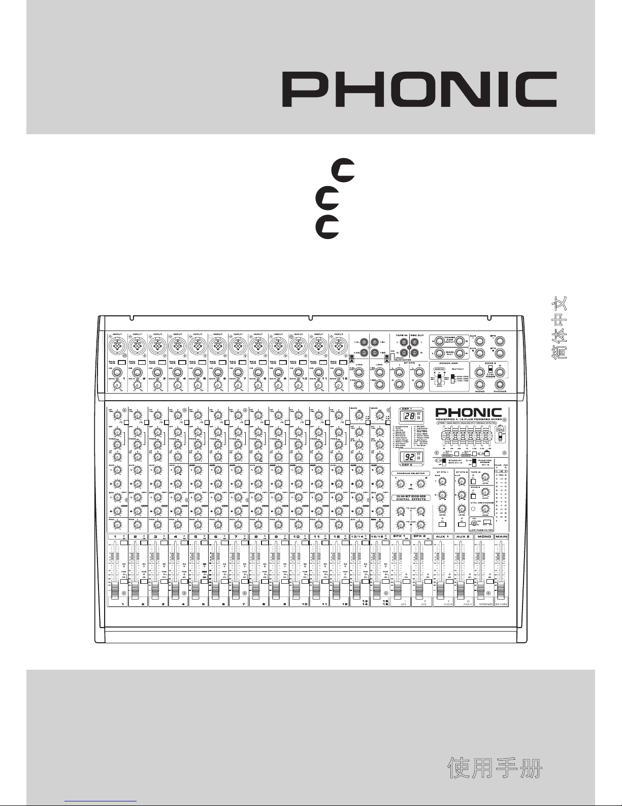
User’s Manual
Manual del Usuario
使用手册
POWERPOD 1860
POWERPOD K-12
POWERPOD K-16
POWERED MIXER
POWERED MIXER
小型调音台
POWERPOD K-16 PLUS
English / Español / 简体中文
PL
US
PL
US
PL
US
Page 2
CONTENTS CONTENIDO
目录
Phonic preserves the right to improve or alter any information within this document without prior notice
Phonic se reserva el derecho de mejorar o alterar cualquier información provista dentro de este documento sin previo aviso
PHONIC保留不预先通知便可改变或更新本文件权利
V1.0 11/12/2008
POWERPOD 1860
POWERPOD K-12
POWERPOD K-16
POWERED MIXER
POWERED MIXER
小型调音台
PL
US
PL
US
PL
US
INTRODUCTION...........................4
FEATURES...................................4
BASIC SETUP...............................4
Getting Started...............................4
Channel Setup...............................4
Optional Rack Mounting................5
The Protective Molded Cover........5
MAKING CONNECTIONS............6
Channel Inputs..............................6
Master Section..............................6
Rear Panel....................................7
CONTROLS AND SETTINGS.......8
Channel Controls..........................8
Digital Effect Processor.................9
Master Section............................10
SPECIFICATIONS......................12
Digital Effect Table......................35
APPLICATIONS..........................36
Adding External Parallel Devices....36
Live Application...........................37
Dimensions.................................38
Typical Connecting Leads...........39
Block Diagrams...........................40
INTRODUCCIÓN..................................15
CARACTERÍSTICAS............................15
CONFIGURACIÓN BÁSICA.................15
Inicio......................................................15
Conguración del Canal........................15
Montaje en Rack Opcional....................16
Cubierta Protectora Moldeada..............16
HACIENDO CONEXIONES..................17
Entradas de Canal.................................17
Sección Principal...................................17
Panel de Dorso......................................18
CONTROLES Y AJUSTE.....................19
Controles de Canal................................19
Procesador Digital de Efectos...............20
Sección Principal...................................21
ESPECIFICACIONES..........................23
TABLA DE EFECTOS DIGITALES.......35
APLICACIONES...................................36
Agregando Dispositivos Externos
Paralelos..............................................36
Aplicación en Vivo................................37
DIMENSIONES....................................38
GUÍAS DE CONEXIONES COMUNES...39
DIAGRAMA DE BLOQUES..................40
简介.................................26
特色.................................26
基本安装.........................26
开始设定.........................26
声道设置.........................26
选配支架安装..................27
保护封套装置..................27
连接设置.........................28
声道输入.........................28
主控制区.........................28
后面板.............................29
控制与设定......................29
声道控制.........................29
数字效果处理器..............30
主控制区.........................31
规格................................ 33
数字效果图表..................35
应用.................................36
外部并联设备....................36
现场应用...........................37
尺寸.................................38
典型连接指导................. 39
方块图.............................40
Page 3
1. Read these instructions before ope rating this
apparatus.
2. Keep these instructions for future reference.
3. Heed all warnings to ensure safe operation.
4. Follow all instructions provided in this document.
5. Do not use this apparatus near water or in locations
where condensation may occur.
6. Clean only with dry cloth. Do not use aerosol or liquid
cleaners. Unplug this apparatus before cleaning.
7. Do not block any of the ventilation openings. Install
in accordance with the manufacturer’s instructions.
8. Do not install near any heat sources such as radiators,
heat registers, stoves, or other apparatus (including
.
9. Do not defeat the safety purpose of the polarized or
grounding-type plug. A polarized plug has two blades
with one wider than the other. A grounding type plug
has two blades and a third grounding prong. The wide
blade or the third prong is provided for your safety. If
the provided plug does not into your outlet, consult
an electrician for replacement of the obsolete outlet.
10. Protect the power cord from being walked on or
pinched particularly at plug, convenience receptacles,
and the point where they exit from the apparatus.
11. Only use attachments/accessories by the
manufacturer.
12. Use only with a cart, stand, tripod, bracket, or
table by the manufacturer, or sold with
the apparatus. When a cart is used, use caution
when movin g the cart/apparatus
combination to avoid injury from tipover.
13. Unplug this apparatus during lighting
storms or when unuse d for long
periods of time.
14. Refer all servicing to service personnel.
Servicing is required when the apparatus has been
damaged in any way, such as power-supply cord or
plug is damaged, liquid has been spilled or objects
have fallen into the apparatus, the apparatus has
been exposed to rain or moisture, does not operate
normally, or has been dropped.
IMPORTANT SAFETY INSTRUCTIONS
CAUTION: TO REDUCE THE RISK OF ELECTRIC SHOCK,
DO NOT REMOVE COVER (OR BACK)
NO USER SERVICEABLE PARTS INSIDE
REFER SERVICING TO QUALIFIED PERSONNEL
The lightning flash with arrowhead symbol, within an
equilateral triangle, is intended to alert the user to the
presence of uninsulated “dangerous voltage” within the
product
’
magnitude to constitute a risk of electric shock to persons.
The exclamation point within an equilateral triangle is in-
tended to alert the user to the presence of important operat-
ing and maintenance (servicing) instructions in the literature
accompanying the appliance.
WARNING: To reduce the risk of or electric shock, do
not expose this apparatus to rain or moisture.
CAUTION: Use of controls or adjustments or performance
of procedures other than those may result in
hazardous radiation exposure.
The apparatus shall not be exposed to dripping or splashing and that no objects with liquids, such as vases,
shall be placed on the apparatus. The MAINS plug is used as the disconnect device, the disconnect device shall
remain readily operable.
Warning: the user shall not place this apparatus in the area during the operation so that the mains switch
can be easily accessible.
CAUTION
RISK OF ELECTRIC SHOCK
DO NOT OPEN
Page 4

4
POWERPOD 1860 / K-12 / K-16
PL
US
PL
US
PL
US
INTRODUCTION
Thank you for your purchase of either the Powerpod K-12 Plus ,
K-16 Plus or 1860 Plus Powered Mixers. All of these mixers are
of a high standard of quality that is synonymous with all Phonic
products, and we are sure will prove to be a valuable investment.
To ensure, however, that you take full advantage of these products, we advise you to carefully read the entire manual before
storing in a place that is easy to remember and easy to access
if necessary.
FEATURES
High-efficiency switching power supply for achieving high
power and light weight
Foot switch allows user to on/mute effect processor and tap
delay control
+48V phantom power switch
2 stereo input channels with 3-band EQ.
Tape in and record out with stereo RCA jacks
2 pre-fader AUX sends and 2 post-fader EFX sends
Stereo 7-band graphic EQ
One professional speaker connector and two 1/4" T S
phone jacks on each power amplifier channel for speaker
connection
Stan d-by featu re allow users to mute all mic rophone
channels
Handle integrated into casing
Mono output with low pass filter, variable frequency from
60Hz to 160Hz
Molded protective cover to help avoid scratching of the
mixer face
Mains power switchable between 115VAC and 230VAC
K-12 Plus and K-16 Plus additions
2 x 500W / 4 Ω bridgeable and patchable power ampliers
Dual effect processor, each containing over 100 effects, with
tap delay and numerous test-tones
Feedback detection
K-12 Plus:
8 Mic/Line input channels with 3-band swept mid-range
EQ and insert
K-16 Plus:
12 Mic/Line input channels with 3-band swept mid-range
EQ and insert
Vocal eliminator
Solid Phonic Pystem speaker enhancement
1860 Plus additions
2 x 400W / 4 Ω bridgeable and patchable power amplier
A single effect processor featuring 100 effects, with tap delay
and numerous test-tones
8 Mic/Line input channels with 3-band EQ and insert
Dual setting Phantom Power switch
BASIC SETUP
Getting Started
1. Ensure all power is turned off on the K-12 Plus, K-16 Plus or
1860 Plus. To totally ensure this, the AC cable should not be
connected to the unit.
2. All faders and level controls should be set at the lowest
level and all channels switched off to ensure no sound is
inadvertently sent through the outputs when the device
is switched on. All levels should be altered to acceptable
degrees after the device is turned on.
NB. Ensure that the rear of the mixer is not less than 30 centimeters
from the wall, as being closer than that may obstruct the cooling
fans and cause overheating.
3. Plug all necessary instruments and equipment into the
device's various inputs as required. This may include line
signal devices, as well as microphones and/or guitars,
keyboards, etc.
4. Plug any necessary equipment into the device's various
outputs. This could include speakers, monitors, signal
processors, and/or recording devices.
NB. No devices other than speakers should be connected to the power
amp outputs. Plugging inappropriate devices into the mixer will
likely cause damage to the device. Also, guitar cables should not be
used to connect ampliers to speakers.
5. Plug the supplied AC cable into the AC inlet on the back of
the device ensure the local voltage level is identical to that
required on your device. On the Powerpod 1860, set the
Voltage Selector to match the local voltage levels.
6. Plug the supplied AC cable into a power outlet of a suitable
voltage.
7. Turn the power switch on
.
Channel Setup
1. To ensure the correct audio levels of each input channel is
selected, every channel should rst be switched off and all
faders set to 0.
2. Choose the channel that you wish to set the level of, and
ensure that channel has a signal sent to it similar to the
signal that will be sent when in common use. For example,
if the channel is using a microphone, then you should
speak or sing at the same level the performer normally
would during a performance. If a guitar is plugged into that
channel, then the guitar should also be used as it normally
would be.
3. Press the PFL button of the channel, allowing you to see
the audio level in the master level meter.
4. Set the gain so the level meter indicates the audio level is
around 0 dB.
5. This channel is now ready to be used; you can stop making
the audio signal.
6. To activate the channel, release the PFL button and
engage the channel's on button.
7. You should now select the next channel to set and go back
to follow steps 1 through 6.
Page 5
5
POWERPOD 1860 / K-12 / K-16
PL
US
PL
US
PL
US
Optional Rack Mounting
1. The K-12 Plus and 1860 Plus are both rack mountable. The
ER K-12 Plus rack mounting kit can be used to install this
product. You will need 13 units of free rack space to install
one of these mixers.
2. To install, rst ensure that the rack you are using will provide
suitable ventilation for the Powered Mixers, as a sealed rack
will cause overheating in the product. Keep 1 U rack space
between the powered mixer and any other device. This will
also ensure overheating does not occur.
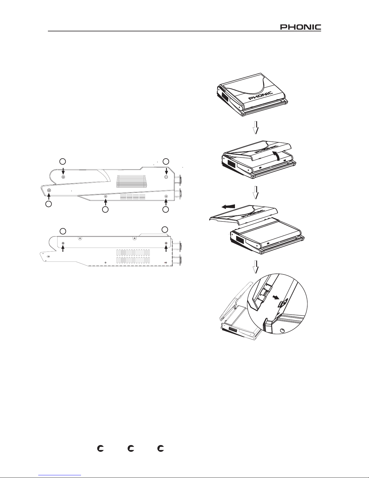
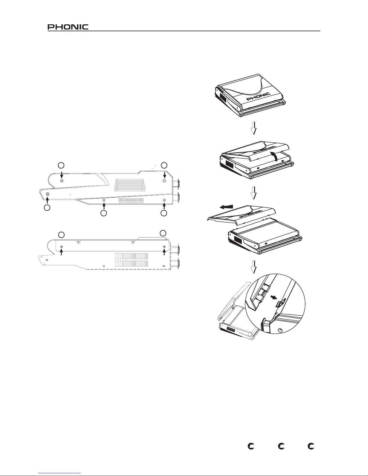
3. Remove the screws
① ~ ⑤ (indicated on the below image)
on both sides of the mixer, along with the side panel.
4. Fasten the rack mount to each side of the mixer using
screws ⑥ ~ ⑦ , as indicated below.
5. Final step: attach the rack mountable mixer to the rack.
1 2
3
4
6
7
5
Opening the cover
Removing the cover
Attaching the cover
Place your ngers on
the two extrusioins
and pull up to open.
Place the small
connecting rods of
the molded cover
underneath the
mixer's hooks.
The Protective Molded Cover
Page 6
6
POWERPOD 1860 / K-12 / K-16
PL
US
PL
US
PL
US
MAKING CONNECTIONS
Channel Inputs
The K-12 Plus and 1860 Plus Powered Mixers supply a total
of 10 input channels, 2 of which accept stereo signals. The
K-16 Plus Powered Mixer, however, provides a total of 14
input channels, also including 2 stereo input channels. The two
stereo channels on each device contain different inputs jacks,
accepting either stereo RCA or 1/4" phone jacks.
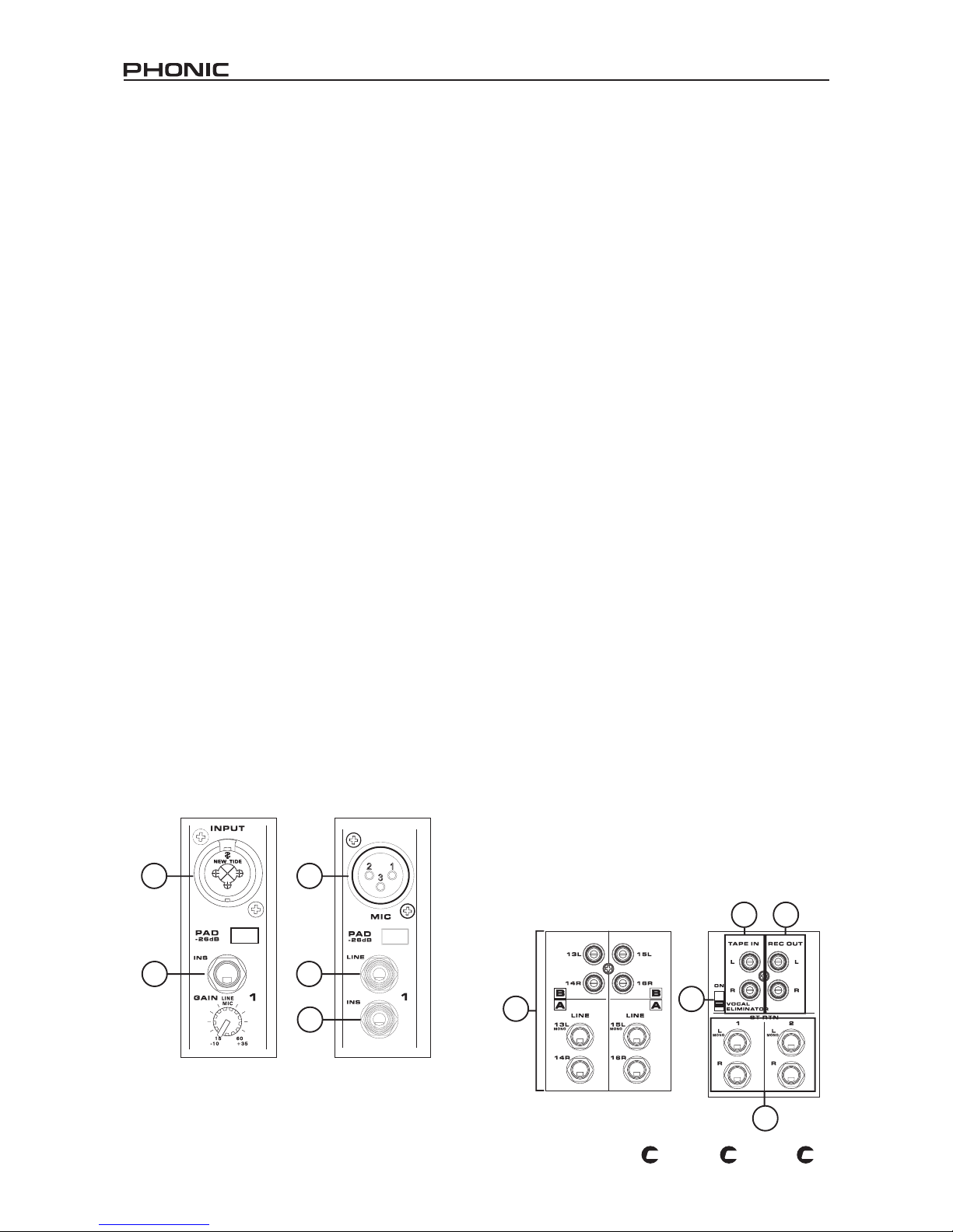
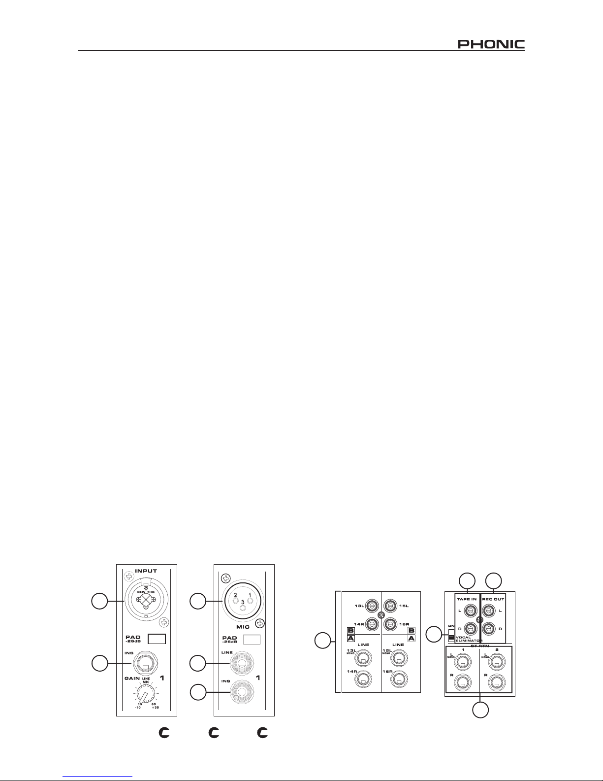
1. XLR + 1/4 Combo Jacks
These combo j acks accept either XLR or 1/4" input s for
bala nced and unbalan ced signals. T hey can be used in
conjunction with microphones such as professional condenser,
dynamic or ribbon microphones - with standard XLR male
connectors, as well as typical 1/4" TRS and 1/4" TS line
inputs for the addition of various music instruments - such as
keyboards, drum machines, electric guitars, as well as a variety
of other electric instruments. With low noise preampliers, these
inputs serve for crystal clear sound replication.
The PAD -26 dB button, located below the combo jack, is used
to attenuate the input signal by 26 dB. This should only be
pushed in when using line input devices.
NB. When using an unbalanced microphone, please ensure phantom
power is switched off. However, when using condenser microphones the
phantom power of the corresponding channel should be activated.
2. Mic Inputs (Powerpod 1860 Plus only)
As the Powerpod 1860 Plus doesn't feature the aforementioned
combo jacks, we've included separate XLR and 1/4" jacks it
features these XLR microphone inputs are for balanced and
unbalanced signals. They can be used in conjunction with
microphones – such as professional condenser, dynamic or
ribbon microphones - with standard XLR male connectors. With
low noise preamplifiers, these inputs serve for crystal clear
sound replication.
NB. When using an unbalanced microphone, please ensure
phantom power is switched off. However, when using condenser
microphones the phantom power of the corresponding channel
should be activated.
3. Line In Jacks (Powerpod 1860 Plus only)
These inputs accept 1/4” TRS and 1/4” TS line inputs for the
addition of various music instruments – such as keyboards,
drum machines, electric guitars, as well as a variety of other
electric instruments.
4. INS (External Device Insert Jack)
The primary use for these TRS phone jacks is for the addition
of external devices, such as dynamic processors or equalizers,
to the corresponding mono input channel. This will require a Y
cord that can send and receive signals of the mixer to and from
an external processor. For more information on Y-Cords, please
refer to Appendix C.
5. Stereo Channel Inputs
Each of the K-12 Plus, K16 and 1860 Plus Powered Mixers
provide 2 stereo input channels, the inputs of which differ
slightly to the mono channels. The stereo RCA inputs are for
the addition of various digital devices (CD players, MP3 players,
laptops, etc), where the 2 Line 1/4" TS jacks are for the addition
of various stereo line level input devices, such as keyboards.
Depending on which set of inputs you wish to use, set the
Stereo A/B button on the channel to the appropriate position.
If you wish to use a monaural device on a stereo input, simply
plug the device’s 1/4" phone jack into the left (mono) stereo
input and leave the right input bare. The signal will be duplicated
to the right due to the miracle of jack normalizing.
Master Section
6. Tape In (L and R)
The rst of these inputs accommodates RCA cables from such
devices as tape and CD players. In addition to these inputs,
however, Phonic has incorporated a mini stereo port for the
inclusion of mini disc (MD), portable CD, and MP3 players (such
as the Apple iPod), as well as laptop computers. The line from
this feed is directed to the Tape In mixing bus, before being fed
through to the Main L/R mixing bus.
7. Vocal Eliminator (K-16 Plus only)
Initiating this switch, featured on the Powerpod K-16 Plus only,
enables you to eliminate vocal sections of any signal fed from
a CD or tape player (or any other input device) into the Tape
In inputs. Using phase cancellation of vocal frequency ranges
between the left and right channels, the K-16 Plus’s vocal
eliminator can effectively remove vocals panned dead center.
8. Record Outputs (L and R)
As with the Tape In ports, these outputs will accommodate
RCA cables, able to be fed to a variety of recording devices.
Also included are mini stereo ports for the addition of recording
devices such as MD players and laptop computers.
9. ST Return Inputs
These TS inputs connect the mixe r with parallel external
devices, such as sub mixers or external effect processors,
receiving the processed signal from another source and feeding
it to the AUX 1, AUX 2 and Main L/R mixing buses. If you wish
to use a monaural device on a stereo return input, simply plug
the device’s 1/4" phone jack into the left (mono) stereo input
and leave the right input bare.
1
4
2
3
4
Powerpod K-16 Plus Powerpod 1860 Plus
6
7
9
8
5
Page 7
7
POWERPOD 1860 / K-12 / K-16
PL
US
PL
US
PL
US
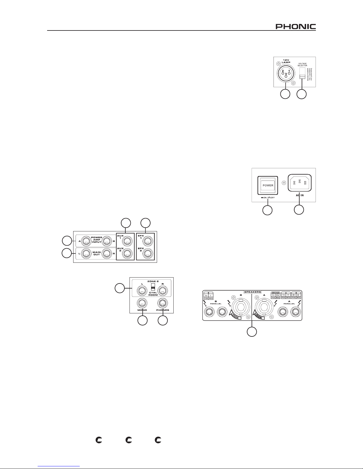
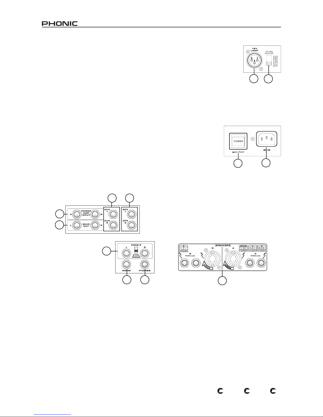
10. Power Amp Inputs
These inputs support 1/4" TS plugs and can be used for the
inclusion of an external line level stereo signals to the built-
in power amplier. If a device is connected to the power amp
inputs, the main feed (according to the power amp control
switch) will automatically bypass the power amp and the
inserted feed will be amplied and sent to the Speaker Outputs
instead.
11. Main Outputs
These two ports will output the nal stereo line level signal sent
from the main mixing bus. The primary purpose of these jacks
is to send the Main output to external devices that may run
in parallel with the mixer. This may include additional power
ampliers, mixers, PA systems, as well as a wide range of other
possible signal processors.
12. Auxiliary (AUX) Outputs
These phone jack outputs are the nal output of line-level signal
fed from the corresponding auxiliary mixing bus, and are best
suited for use with stage monitors. Feeding the output from the
Auxiliary outs to an amplier - and possibly an equalizer - and
then to a floor monitor speaker allows artists to monitor their
own instruments or vocals whilst performing.
13. EFX (Effect) Outputs
These 1/4" TS outputs are the nal output from the EFX send
mixing bus. This feed may be used to connect to an external
digital effect processor, or even to an amplier and speakers,
depending on your desired settings.
14. Control Room / Zone 2
Outputs and Switch
These phone ja c k ou tputs
feed the signal from either the
Control Room or Zone 2 control
pan e ls. T he corr e s pondi n g
switch alterna t e s the feed
between the audio from the
CTRL RM/PHONES control and
that of the Zone 2 control. The
Zone 2 output is best suited to act as side ll, supplying audio
to indoor areas that the sound from the main speakers does
not reach. The control room's signal, on the other hand, can be
used for the inclusion of an active monitor within a booth. Well,
they're our suggestions, but it's your call.
15. Mono Output
This 1/4" TS output feeds the audio signal from the mono
mixing control located on the main mixing panel. This is best
suited for use with a mono sound system, or for the addition of
a subwoofer to your set of speakers, adding more punch to low
frequency sounds.
16. Phones Output
This stereo output port is suited for use with headphones,
allowing monitoring of the mix. The audio level of this output is
controlled using the CTRL RM/PHONES control.
Rear Panel
17. Voltage Selector
This switch allows you to select from
2 mains power modes, 115 VAC / 60
Hz (allowing you to use the device in
Countries with voltages between 100V
and 120V) or 230 VAC / 50 Hz (allowing
you to use the device in Countries with
voltages between 200V and 230V).
NB. Using incorrect voltages can cause irreversible damage to the mixer.
All care must be taken in selecting the voltage appropriate to your zone.
If unsure of local voltage levels, contact a knowledgeable source before
using this mixer.
18. 12V Lamp
This XLR port allows you to attach a 12 Volt gooseneck lamp,
allowing better visibility in areas with poor light.
19. Power Button
This button is used to turn
th e d e vi ce o n a n d o f f .
Before tur ning the device
on, however, ensure all level
controls are at a minimum.
20. Mains Power Inlet
This port is used to plug the
socket end of the included
AC cab le. T he othe r e nd
should be connected to an
appropriate power source.
21. Speaker Outputs
These jacks are used to connect to speakers, fed from the
internal power amp. The first set of outputs are professional
speaker connectors; to use these, insert an appropriate four pin
plug into the connector, and twist to lock into place. The second
set of outputs are 1/4" phone jacks. To use these, simply insert
an appropriate 1/4" TS plug into them. The total loading for
speakers should be no more than 4 ohms per channel, or 8
ohms for a bridge mono connection.
One Speaker per Channel: When connecting a single speaker
to each channel's output, speakers with an impedance between
4 and 8 ohms should be used. This is the case for both the
Phone Jack and Professional Speaker Connectors.
Two Speakers per Channel: When connecting two speakers
to the Speaker Outputs, the loading of each speaker should
be between 8 and 16 ohms (as two 8 ohm speakers will form a
total loading of 4 ohms, two 16 ohm speakers a total loading of
8 ohms, etc).
Bridge Mono: When using bridge mono mode, Professional
Speaker output A should be used only. The total loading should
be no less than 8 ohms.
NB. Only use passive speakers in conjunction with the Speaker outputs,
as to avoid damaging any equipment.
10
11
12
13
14
15 16
18
17
19
20
21
Page 8
8
POWERPOD 1860 / K-12 / K-16
PL
US
PL
US
PL
US
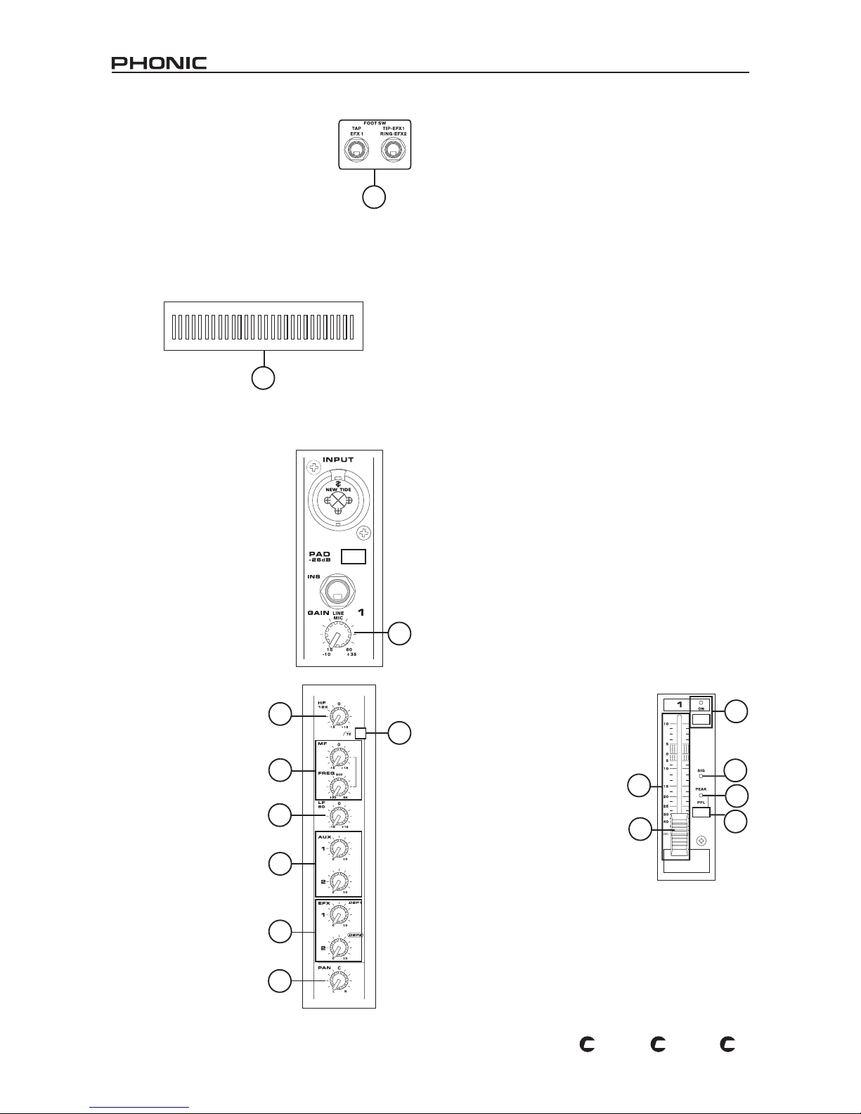
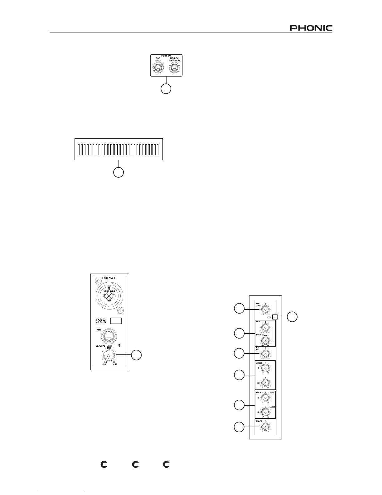
22. Foot Switch Jacks
These ports are for the inclusion of a foot
switch, used to remotely adjust properties of
the built-in Digital Effect processor. The left
jack is used to adjust the tap delay properties,
where the right jack is used for the turning
on and off of digital effects (these are for use
with digital effect processor 2 on the K-12
Plus and K-16 Plus).
23. Fans
These vari-speed fans are used for the cooling of the mixer.
Do not obstruct in any way to ensure the product does not over
heat.
CONTROLS AND SETTINGS
Channel Controls
It is important that all channels are
independently disabled while not in
use. Lower the corresponding level
control when activating a channel;
the volume level should then be set
to an appropriate level.
24. Gain Control
This controls the sensitivity of the
input signal, which is sent to the
corresponding input channel. The
gain should be adjusted to a level
that all ows the maxim um use of
the audio, while still maintaining
the quality of the feed. This can be
accomplished by adjusting it
to a level that will allow the
peak indicator occ asionally
illuminate.
25. High-Pass Filter (75 Hz)
Th is b utto n w ill activ ate a
high-pass filter that reduces
all frequencies below 75 Hz at
18 dB per Octave, helping to
remove any unwanted ground
noise or stage rumble.
26 . HF ( High Frequ ency )
Control
This control is used to give a
shelving boost or cut of 15
dB to high frequency (12 kHz)
sounds. This will adjust the
am o unt o f treb l e incl u d ed
in the audio of the channel,
adding strength and crispness
to sounds such as gui tars,
cy mba ls, synthesizers a nd
Michael Jackson.
27. MF (Middle Frequency) Control
This control is used to provide a peaking style of boost and cut
to the level of middle frequency sounds at a range of 15 dB.
The mono channels on the K-12 Plus and K-16 Plus provides
a sweep control, allowing you to select a center frequency
between 100 Hz and 8 kHz, whereas all channels on the 1860
Plus's (and stereo channels on the K-12 Plus and K-16 Plus),
the center frequency is set at 2.5 kHz.
Changing middle frequencies of an audio feed can be rather
difcult when used in a professional audio mix, as it is usually
more desirable to cut middle frequency sounds rather than
boost them, soothing overly harsh vocal and instrument sounds
in the audio.
28. LF (Low Frequency) Control
This control is used to give a shelving boost or cut of 15 dB
to low frequency (80 Hz) sounds. This will adjust the amount
of bass included in the audio of the channel, and bring more
warmth and punch to drums, bass guitars and Isaac Hayes.
29. Auxiliary Controls 1 and 2
These controls alter the signal level that is being sent to the
auxiliary 1 and 2 mixing buses, the signal of which is suitable for
connecting stage monitors, allowing artists to listen to the music
that is being playing.
30. Effect (EFX) Controls 1 and 2
These controls alter the signal level that is sent to the EFX 1
and 2 outputs, which can be used in conjunction with external
signal processors (this signal of which can be returned to mixer
via the stereo return inputs), or simply as additional auxiliary
outputs for any means required. These controls also adjust the
level of audio that is sent to the built-in digital effect engines (in
the case of the Powerpod 1860, EFX 2 controls the signal sent
to the built-in effects processor).
31. PAN/BAL
This alternates the degree or level of audio that the left and right
side of the main mix should receive. On mono channels, this
control will adjust the level that the left and right should receive,
where as on a stereo channel, adjusting the BAL control will
attenuate the left or right audio signals accordingly.
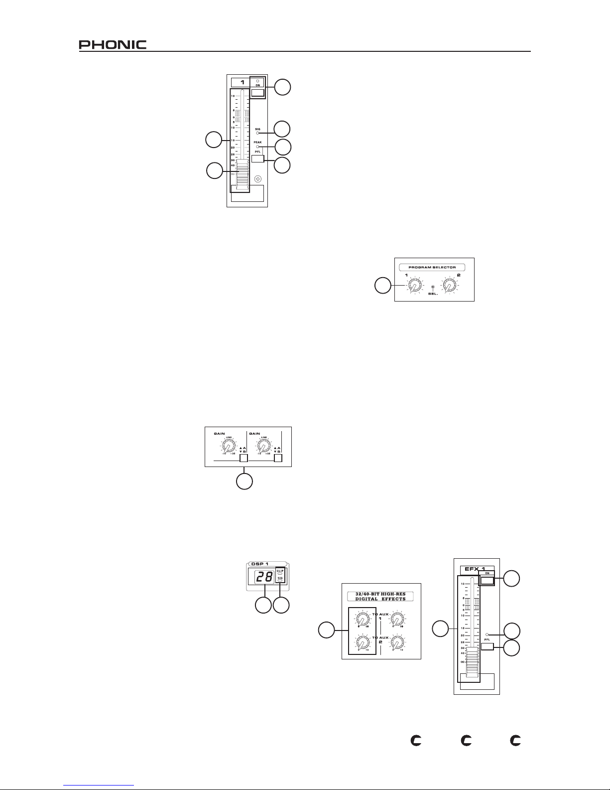
32. On Button and Indicator
This turns the channel on, allowing
the user to use the feed from the
ch anne l's inpu ts to s uppl y t he
MAIN L/R, MONO, AUX 1 and 2
and the EFX 1 and 2 buses. The
corr esponding indic ator will be
illuminated when turned on.
When the channel is not activated,
the PFL button will still allow the
user to send the channel's audio
signal to the CTRL RM/PHONES
mixing bus for monitoring purposes.
33. Peak Indicator
This LED indicator will illuminate when the device hits high
peaks, 6 dB before overload occurs. It is best to adjust the gain
of the channel so that the PEAK indicator lights up on intervals.
This will ensure a greater dynamic range your audio.
22
23
24
26
25
27
28
29
30
31
32
34
33
35
25
36
Page 9
9
POWERPOD 1860 / K-12 / K-16
PL
US
PL
US
PL
US
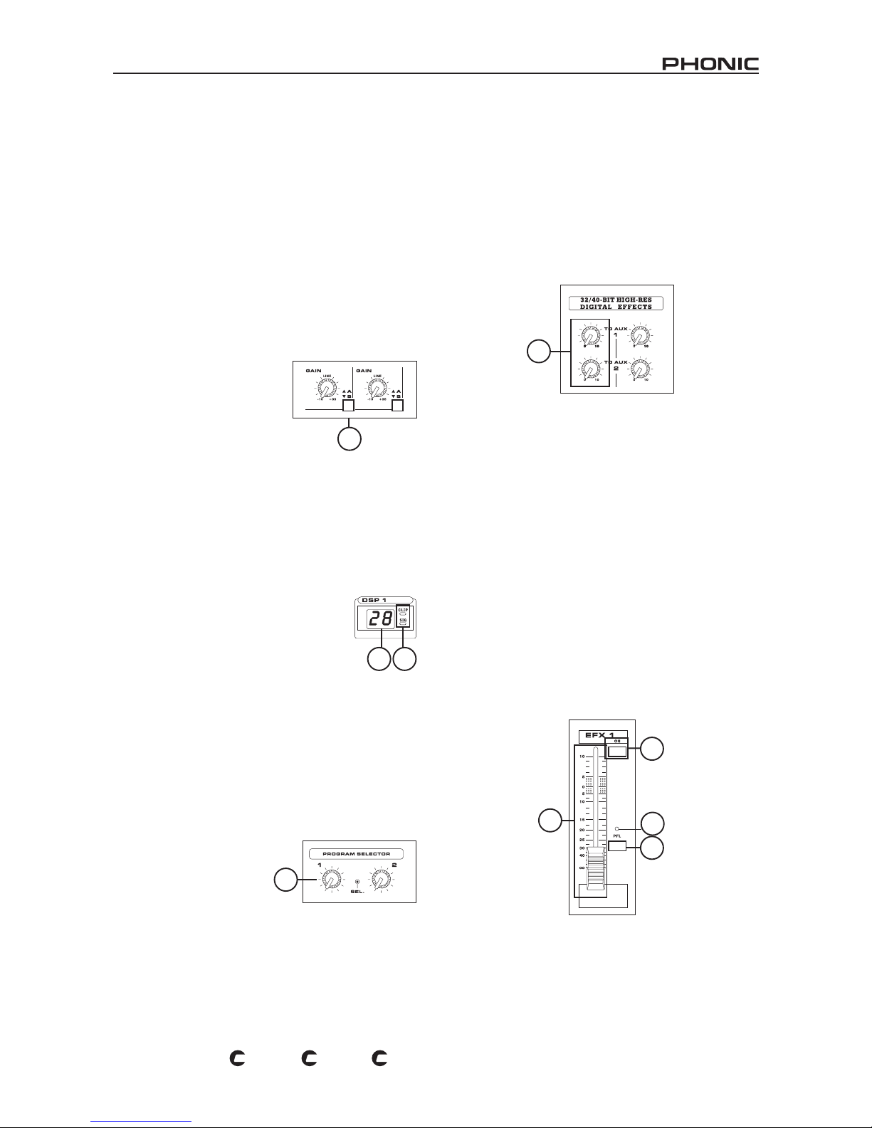
34. SIG Indicator
Th is LED ind icat or will ill umin ate whe n a sig nal of the
corresponding channel reaches -20dB, giving an indication of
any signal being sent through to the input channel.
35. PFL button and Indicator
The PFL - or Pre-Fader Listen - button is pushed to allow the
signal of a corresponding channel to be sent to the CTRL
RM/PHONES control (pre-fader, post-EQ), for use with either
headphones or studio monitors. This allows easier setting of
the input gain and tracking of audio by sound engineers. The
corresponding green LED will illuminate when PFL is activated.
36. Channel Level Control (Fader)
This control will alter the signal level that is sent from the
corresponding channel to the main mixing bus.
37. Stereo Channel A/B Button
When this button is released, the
co rresp ondi ng s tere o cha nnel
on the K-12 Plus, K-16 Plus and
1860 Plus’s will receive its signal
from the 1/4” input s. Howev er,
when this button is pushed in, the
stereo c hannel will recei ve the
corresponding stereo RCA input’s
signal.
Digital Effect Processor
The K-12 Plus and K-16 Plus both supply you with two effect
channels, where the 1860 provides only one.
38. Digital Effect Display
Th i s 2 - digi tal nu meri c dis p lay shows the
program number that is currently applied to your
EFX audio signal. When you rotate the Program
control, you can scroll through different program
numbers; however the display will revert back
to the original program if a new program is
not selected within a few seconds. For a list
of available effects, please observe the Digital
Effect Table in Appendix A.
39. Sig and Clip Indicators
Located within the Digital Effect Display are Clip and Sig LEDs.
The Sig LED will light up when any signal is received by the
effect processor, and the Clip LED will light up shortly before
excessive signals are dynamically clipped. If the Clip LED lights
up too often, it may be advisable to turn down the EFX master
control to ensure the signal level is not excessive.
40. Program Control
This control is used to scroll
through the various effects.
Turning the control clockwise
will allow users to ascend into
higher program numbers, and
turnin g it counter-clo ckwise
will allow users to descend into lower program numbers. When
turning to a new program, a small LED will ash until you push
the program knob down – this will apply the effect. When a tapdelay effect is selected, pressing this control will allow users to
select the tap-delay time.
By pushing the button several times, the effect processor
interprets the time between last two pushes and remembers this
as the delay time – until the button is pushed again. This is kept
even after the power is turned off. When the tap delay effect is
selected, a small LED (located between the two digit display)
will ash within the digital effect display window at the selected
intervals. To see the list of available programs, please check
the Digital Effect Table in Appendix A.
41. Auxiliary Controls 1 and 2
These controls alter the level of audio that is being sent to the
corresponding auxiliary mix from the corresponding Digital
Effect Processor.
42. DSP Effect On Button and Indicator
This button is pushed to turn the corresponding effect panel on
or off. When the effect processor is turned on, the corresponding
LED illuminates.
43. Peak Indicator
This LED indicator will illum in ate when the Digital Effect
Processor overloads. It is best to adjust the EFX 1 and 2
controls on input channels so as to ensure the PEAK indicator
does not light up. This will ensure a greater quality of audio.
44. PFL Button and Indicator
This PFL - or Pre-Fader Listen - button is pushed to allow the
processed signal of the digital effect processor to be sent to
the CTRL RM/PHONES control (pre-fader), for use with either
headphones or studio monitors. This allows easier tracking of
audio by sound engineers. The corresponding green LED will
illuminate when PFL is activated.
45. DSP Effect Faders 1 and 2
Each of these controls adjusts the level of the audio to be sent
from the corresponding Digital Effect Processor to the main
mixing bus.
37
38 39
40
41
42
43
45
44
Page 10
10
POWERPOD 1860 / K-12 / K-16
PL
US
PL
US
PL
US
Master Section
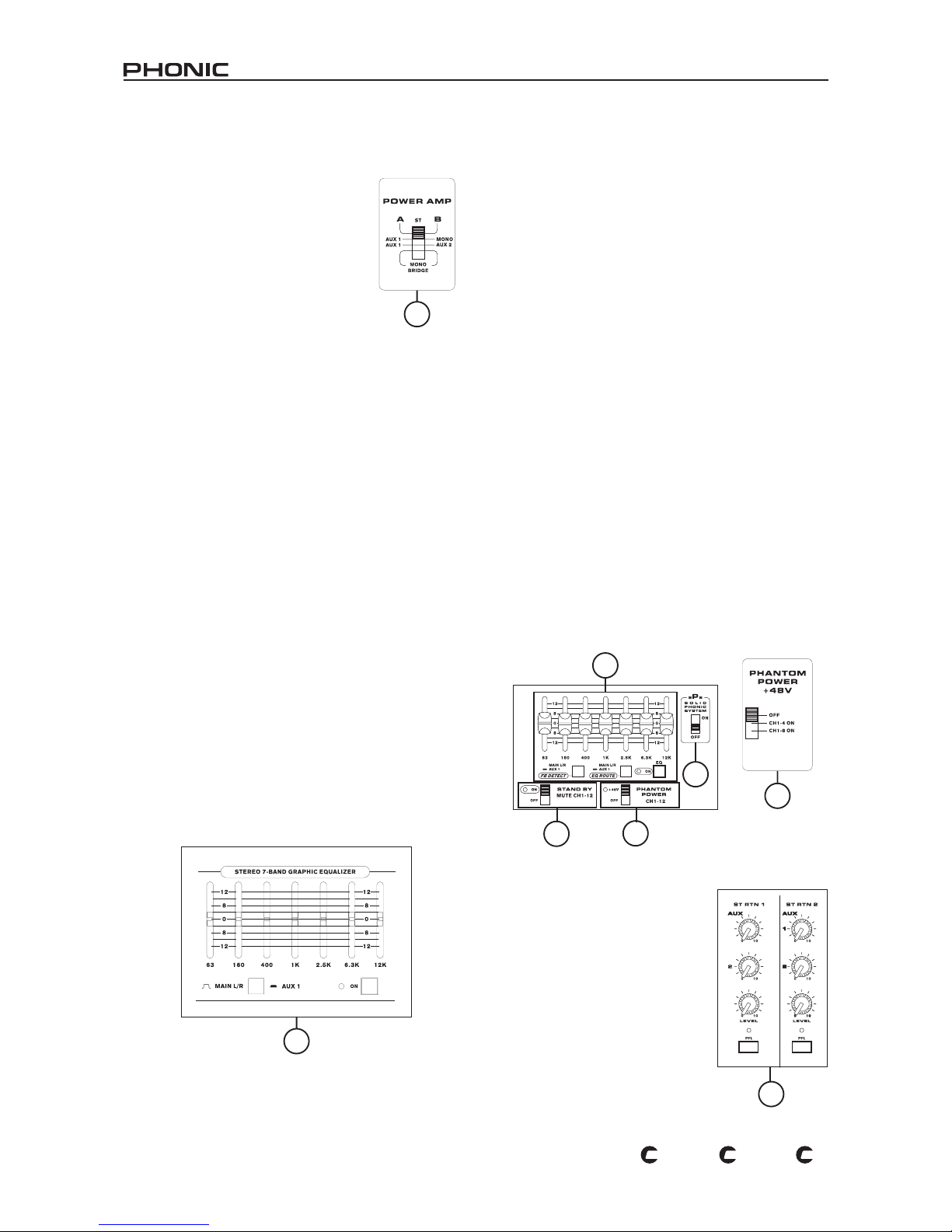
46. Power Amp Control Switches
These switches control the activity and the
strength of the power amp. Using the left
switch can alternate between the different
signals which can be processed by the builtin power amp and routed to the main speaker
outputs on the rear of the device. This switch
allows you to select from: Stereo, the final
level of which is adjusted by the MAIN L/R
fader; AUX 1/MONO, the final level of which
is adjusted by the AUX 1 fader and MONO
fader; AUX 1/AUX 2 outputs, the nal level of
which is adjusted by the AUX 1 and 2 faders,
and; MONO BRIDGE, which is output via professional speaker
output A only, and the volume of which is controlled by the
MONO fader.
NB. When using a mono bridge connection, do not connect a speaker to
either the 1/4" phone jacks, or the professional speaker jack B speaker
connector, located on the rear of the mixer.
The amplication power can be changed using the right switch
from 100 Watts for each channel, to 300 or 500 Watts per
channel on the K-12 Plus and K-16 Plus only, the selection of
which will depend on the size of a venue and the input capacity
of the speakers you have chosen to use. This feature is not
included in the Powerpod 1860 Plus.
47. Solid Phonic System (K-16 Plus only)
Using this switch (featured on the K-16 Plus only) will enable the
user to give both the high and low frequencies of their sound a
little boost to improve the overall robustness of the audio. There
is no guarantee your sound will improve with the sPs activated,
however, so it’s probably desirable to audition the mixer’s sound
with this switch on and off, and decide which is better for your
purposes.
48. Graphic Equalizer
This stereo 7 band graphic equalizer allows users to adjust the
frequency response of a signal, with a maximum of 12 dB of
boost or cut for each of the frequencies. The AUX 1 / L/R button
alternates the use of the equalizer between the AUX 1 bus and
MAIN L/R bus signals, accordingly. When L/R is selected, the
equalizer is applied to not only both the main stereo signal (Main
and Speaker outputs), but also to the mono signal. Pushing the
on button in activates the equalizer, which is accompanied by
an illuminated LED.
One feature, built into the Powerpod K-12 Plus and K-16
Plus's graphic equalizer, is a Feedback Detection System.
The individual LEDs located on the sliding VR controls of the
equalizer will illuminate when feedback occurs on that particular
frequency band. By reducing the level of that frequency band
you can quite effectively remove the feedback on that frequency;
after which the LED will turn off. If the FBD button is pushed
in, the feedback detection is active for the nal AUX 1 signal,
whereas if it is released, the feedback detection is active for the
MAIN L-R signal. It is recommended that users switch the the
AUX 1 / L/R button to the same setting as the FBD button, as to
ensure simpler adjustment of frequencies that have produced
feedback.
49. Stand-by Switch and Indicator
This switch enables and disables a mute of channels 1 through
to 15/16 on the K-16 Plus, and channels 1 through to 11/12
on the K-12 Plus and 1860 Plus. This feature is handy in live
performances, due to the fact that the Tape In and stereo AUX
Returns are not muted when it is activated, allowing an audio
signal from CD players or other input devices to be played
during performance breaks, while still ensuring microphones
fail to produce hideously sounding feedback (as opposed to
feedback that actually sounds good, of course). Pushing of the
stand-by switch is accompanied by an illuminated LED.
50. Phantom Power Switch
When this switch is in the on position it activates +48V of
Phantom Power for channels 1 through to 8 on the K-12 Plus,
and channels 1 through to 12 on the K-16 Plus, allowing
condenser microphones to be used o n these channels.
Activation of Phantom Power is accompanied by an illuminated
LED on these two models. On the Powerpod 1860 Plus, this
switch has 3 positions, allowing users to activate phantom
power for channels 1 through 8, channels 1 through 4 only, or
no channels at all.
46
48
Powerpod 1860 Plus
48
49
50
47
50
Powerpod
1860 Plus
51. Stereo Return Controls
These controls are used to adjust the
audio level that is received by the stereo
return input jacks. They consist of 2
auxiliary level controls, for adjusting the
level to be sent to the auxiliary mixing
bus, and a level control, for adjusting
levels to be sent to the main mixing
bus.
The corre sponding PFL (Pr e-Fader
Li s ten) butto ns a llow you t o sen d
the audio of the stereo return inputs
di rectly to t he CTRL R M/PH ONE S
control, unaltered by any level controls.
Activation of the PFL is accompanied
by an illuminated LED.
51
Page 11
11
POWERPOD 1860 / K-12 / K-16
PL
US
PL
US
PL
US
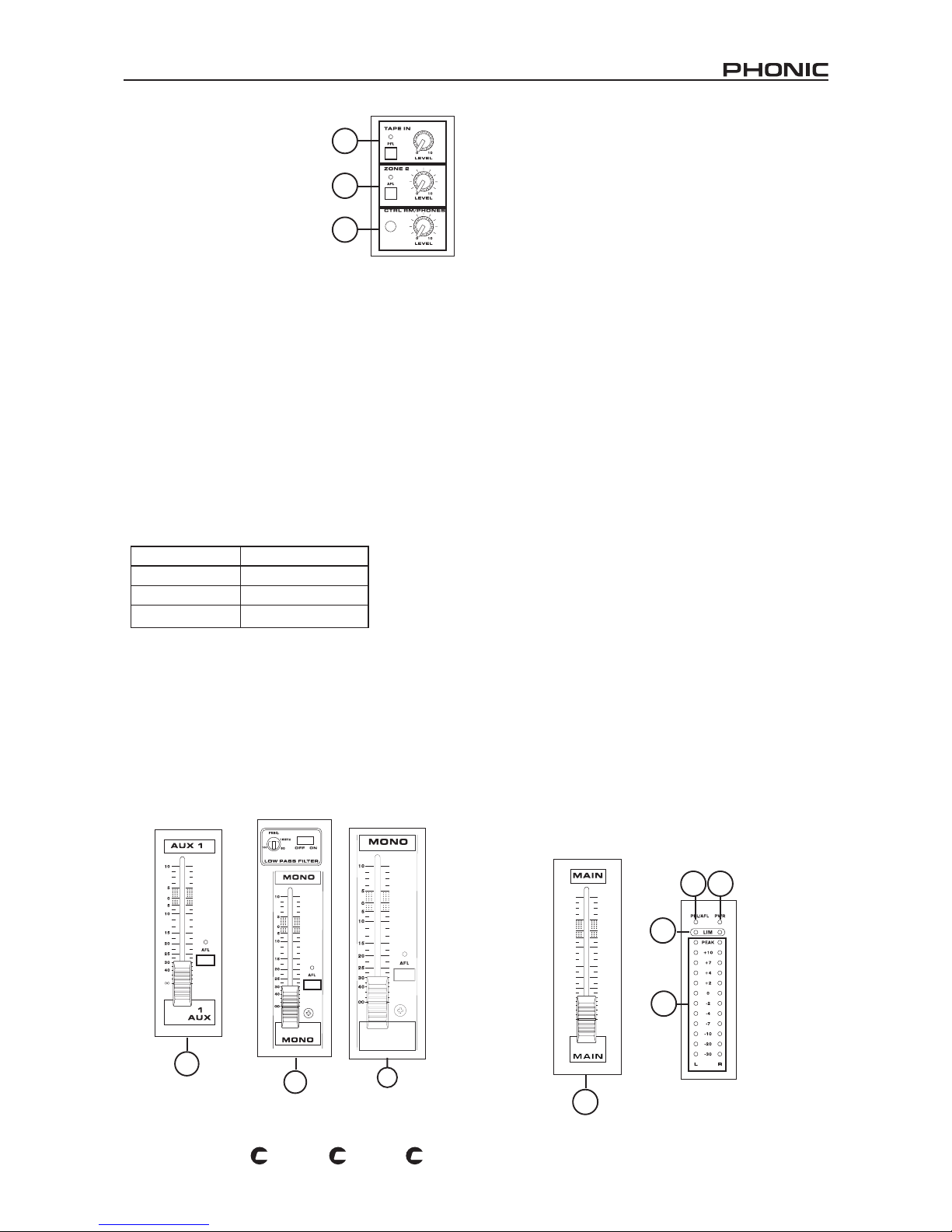
52. Tape In Controls
This control is used to adjust the level
of the Tape In input that will be sent
to the main mix. The corresponding
PFL (Pre Fader Listen) button allows
you to send the audio of the Tape In
to the CTRL RM/PHONES control. In
this instance, the Tape In Control in
no way affects the signal sent to the
PFL/AFL bus.
53. Zone 2 Controls
This control is used to adjust the level of the Zone 2 feed
(duplicated from the MAIN L/R mix) that will be sent to the Zone
2 output. The corresponding AFL (After Fader Listen) button
allows you to send the Zone 2 audio feed to the CTRL RM/
PHONES control. Activation of the AFL is accompanied by an
illuminated LED.
54. Control Room / Phones Control
This knob controls the level of the audio to be sent to the CTRL
RM/PHONES Output, located on the top panel of the K-12
Plus, K-16 Plus and 1860 mixers. Any PFL that is activated has
priority over all other signals, and is able to run simultaneously
with another PFL signal. If no PFL buttons are pushed down,
then any AFL that is activated will be used instead (an AFL can
also work simultaneously with other AFLs). Likewise, if neither a
PFL nor an AFL is active, the MAIN L/R mix will be used.
Priority of Control Room/Phones Feed
55. Auxiliary 1 and 2 Controls (Faders)
These controls alter the audio level that will be sent to the AUX
outputs, suitable for connecting to floor monitors, as well as
external processing devices, if required. The corresponding
AFL (After-Fader Listen) buttons allow you to send the audio
of the auxiliary mixing bus to the CTRL RM/PHONES control,
after being altered by the corresponding fader (ie. after-fader).
Activation of the AFL is accompanied by an illuminated LED.
56. Mono Output Controls
The Mono Channel fader will adjust the nal audio level that is
to be sent to the Mono output jack. The corresponding AFL (After
Fader Listen) button allows you to send the post-fader mono
audio signal to the CTRL RM/PHONES control.
The corresponding Low Pass Filter controls, not featured on the
1860 Plus, are used to reduce unwanted high frequency sounds
of the mono output at a rate of 18 dB per octave, for a clearer
bass sound when using subwoofers. The switch turns the Low
Pass Filter on and off, where the accompanying control adjusts
the minimum cut frequency between 60 and 160 Hz.
57. Master Level Control
This fader controls the nal volume level of the Main L/R audio
to be sent to the built-in power amplier and respective outputs.
58. Power Indicator
The Power Indicator, located next to the PFL/AFL indicator, will
light up when the power of the Powerpod K-12 Plus, K-16 Plus
or 1860 Plus is on.
59. PFL/AFL Indicator
The PFL/AFL indicator on the top of this meter is bi-colored, and
illuminates green when a PFL switch is active and red for an
AFL. Due to the fact that any PFL has priority over any AFL, if
both an AFL and PFL are activated, only the green PFL indicator
will illuminated and processed by the CTRL RM/PHONES
control area.
60. Limiter Indicators
There are 2 limiters built-in the stereo power amplier featured
in the Powerpod K-12 Plus, K-16 Plus and 1860 Plus. The
limiters are activated and the indicator will illuminate when the
Power Amplifier's signal level becomes too high, warning the
user of the possibility of overload. If this happens too often,
ensure you to turn down the corresponding input level control
for the Power Amplier's source, as selected by the Power Amp
Control switches, to a reasonable level.
61. Stereo Level Meter
This level meter offers a visual display of the stereo Main L/R
output level. Each channel's 12-segment level meter consists of
green, yellow and red colored LEDs, including a peak indicator,
showing levels between -30dBu and +10dBu. When either a
PFL or AFL is activated, the master level meter offers a visual
display of the signal level of the PFL or AFL, monitored on
the same aspects as the level meter normally would. See the
Control Room / Phones section (54) for a little more information
on PFLs and AFLs.
52
53
54
Priority Feed
Highest PFL
Medium AFL
Lowest MAIN L/R
55
56
56
Powerpod 1860 Plus
57
60
61
59 58
Page 12
12
POWERPOD 1860 / K-12 / K-16
PL
US
PL
US
PL
US
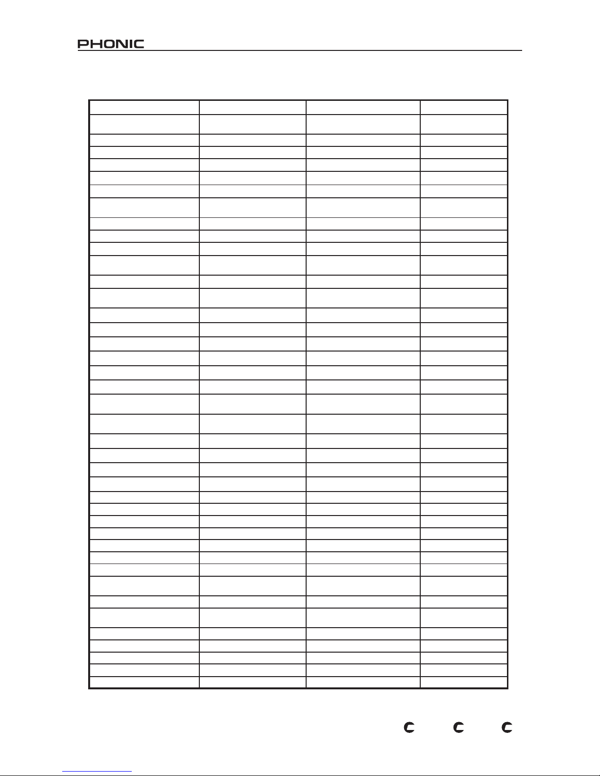
SPECIFICATIONS
POWERPOD K-12 Plus POWERPOD K-16 Plus POWERPOD 1860 Plus
POWER AMP, output power in
Watts @THD<0.5%, 1KHz
Number of Power Channels 2 2 2
Limiters 2 2 2
8 ohms per Channel 330 330 260
4 ohms per Channel 500 500 400
8 ohms Bridge Mono 1000 1000 800
Power Amp Select Switch 500W+500W, 300W+300W,
100W+100W
500W+500W, 300W+300W,
100W+100W
N/A
Inputs
Total Channels 10 14 10
Balanced Mono Mic/Line Channels 8 (XLR + 1/4” combo jack) 12 (XLR + 1/4” combo jack) 8 (XLR + 1/4” combo jack)
Stereo Line Channels with mic
preamp
2 (XLR & 2x 1/4”) 2 (XLR & 2x 1/4”) 2 (XLR & 2x 1/4”)
Stereo Aux Returns 2 2 2
2T Input 1 (1 x Mini stereo & 2 x RCA
jacks)
1 (1 x Mini stereo & 2 x RCA jacks) 1 (1 x Mini stereo & 2 x
RCA jacks)
Outputs
Main L/R Stereo 2 x 1/4” TS, Unbal. 2 x 1/4” TRS, Unbal. 2 x 1/4” TS, Unbal.
Main Mono 1/4” TS, Unbal. 1/4” TRS, Unbal. 1/4” TS, Unbal.
Aux Send & Effect Send 4 x 1/4” TS, Unbal. 4 x 1/4” TRS, Unbal. 4 x 1/4” TS, Unbal.
Phones 1 1 1
Control RM or Zone 2 Output 2 x 1/4” TS, Unbal. 2 x 1/4” TRS, Unbal. 2 x 1/4” TS, Unbal.
Rec Out 1 x Mini stereo, 2 x RCA jacks 1 x Mini stereo, 2 x RCA jacks 1 x Mini stereo, 2 x RCA
jacks
Speaker Output 1 x Speakon & 2 x 1/4” TS per
channel
1 x Speakon & 2 x 1/4” TRS per
channel
2 x Speakon & 4 x 1/4” TS
Channel Strips 10 14 10
Aux Control 4 4 4
Pan/Balance Control Yes Yes Yes
Channel On/Mute Yes Yes Yes
Channel Solo/PFL with metering Yes Yes Yes
LED Indicators On, Peak, Signal, PFL On, Peak, Signal, PFL On, Peak, Signal, PFL
Volume Controls 60mm faders 60mm faders 60mm faders
Insert Yes Yes Yes
Master Section
Aux Send Masters 2, 60mm fader 2, 60mm fader 2, 60mm fader
Effects Return to Monitor 4 4 3
Phones/control RM/Zone 2 level
control
Yes Yes Yes
Control Room Mode ST, PFL/AFL ST, PFL/AFL ST, PFL/AFL
Faders 2 x Efx, Aux 1, Aux 2, Mono, Main
L/R (60mm fader)
2 x Efx, Aux 1, Aux 2, Mono, Main
L/R (60mm fader)
Efx, Aux 1, Aux 2, Mono,
Main L/R (60mm fader)
Metering
Number of Channels 2 2 2
Segments 13 13 13
Phantom Power Supply +48V DC +48V DC +48V DC
Switch Master + 10 Master + 14 Master + 10
Page 13
13
POWERPOD 1860 / K-12 / K-16
PL
US
PL
US
PL
US
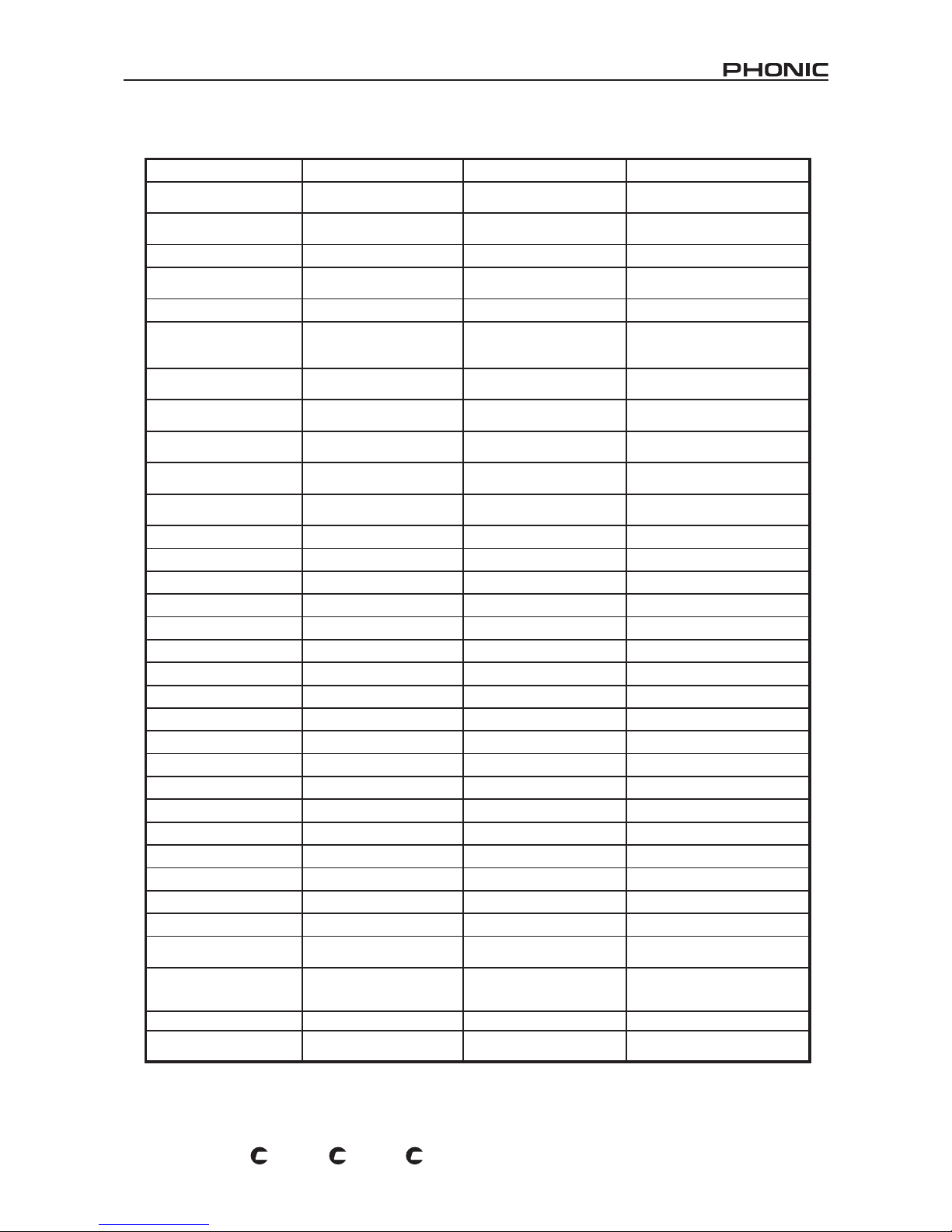
THD
Power output, 1KHz, 20Hz to
20KHz
@250 Watts, 4 ohms <0.5% @250 Watts, 4 ohms <0.5% @200 Watts, 4 ohms <0.5%
Any output, 1KHz @ +14dBu,
20Hz to 20KHz, channel inputs
<0.3% <0.3% <0.3%
CMRR
1 KHz @ -60dBu, Gain at
maximum
80 dB 80 dB 80 dB
Crosstalk
1KHz @ 0dBu, 20Hz to 20KHz
bandwidth, channel in to main
L/R outputs
Channel fader down, other
channels at unity
<-63 dB <-63 dB <-63 dB
Channel muted, other channels
at unity
<-64 dB <-64 dB <-64 dB
Frequency Response (mic
input to output)
20Hz ~ 20KHz, line level o/p @
+4dBu into 600ohms
+0/-2 dB +0/-2 dB +0/-2 dB
20Hz ~ 20KHz, power amp o/p
1 watt into 8ohms
+0/-2 dB +0/-2 dB +0/-2 dB
Maximum Level
Mic Preamp Input +10 dBu +10 dBu +10 dBu
All Other Inputs +22 dBu +22 dBu +22 dBu
Unbalanced outputs +22 dBu +22 dBu +22 dBu
Impedance
Mic In 5K ohms 5K ohms 5K ohms
Line In 50K ohms 50K ohms 50K ohms
All Other Inputs (except inserts) 10K ohms 10K ohms 10K ohms
RCA 2T Outputs 600 ohms 600 ohms 600 ohms
All Other Outputs 150 ohms 150 ohms 150 ohms
Equalization 3-band, ±15 dB 3-band, ±15 dB 3-band, ±15 dB
Low EQ 80 Hz 80Hz 80 Hz
Mid EQ 100-8K Hz, sweepable 100-8K Hz, sweepable 2.5 KHz
Second Mid EQ (St channel) 2.5 KHz 2.5 KHz 2.5 KHz
Hi EQ 12 KHz 12 KHz 12 KHz
Low Cut Filter 75Hz (-18dB/oct) 75 Hz (-18dB/oct) 75Hz (-18dB/oct)
Microphone Preamp E.I.N.
150 ohms terminated, max gain <-122 dBm <-122 dBm <-122 dBm
Power Consumption
(Average Maximum)
500 Watts 500 Watts 400 Watts
Power Requirement 100 - 120 VAC, 220 - 240 VAC,
50 / 60 Hz, depending on region
settings
100 - 120 VAC, 220 - 240 VAC,
50 / 60 Hz, depending on region
settings
Switchable between
115VAC &
230VAC, 50/60 Hz
Net Weight 14.5 Kg (31.9 lbs) 19.5 Kg (43.0 lbs) 14.3 Kg (31.5 lbs)
Dimensions (W x H x D) 483 x 142.6 x 466.2 mm
(19” x 5.6” x 18.4”)
583.2 x 142.6 x 466.2 mm
(23” x 5.6” x 18.3”)
448 x 147 x 465 mm
(17.6” x 5.8” x 18.3”)
Page 14
Page 15

15
POWERPOD 1860 / K-12 / K-16
PL
US
PL
US
PL
US
INTRODUCCIÓN
Gracias por su compra de cualquiera de las mezcladoras
Powerpod K-12 Plus, K-16 Plus o 1860 Plus Powered Mixers.
Todas estas mezcladoras vienen de un alto estándar de calidad
que es sinónimo en todos los productos de Phonic, además
estamos seguros que demostrarán ser una valiosa inversión.
De cualquier manera, para asegurarnos de que tomará toda la
ventaja de estos productos, le sugerimos que lea cuidadosamente
el manual entero antes de guardarlo en algún lugar de fácil
acceso y de recordar, en caso necesario.
CARACTERÍSTICAS
Suministro de energía de alta eciencia para lograr alta
potencia y peso ligero
Interruptor de Pedal, permite a los usuarios encender o
silenciar el procesador de efectos y el control de Tap Delay.
Interruptor de fuente fantasma de +48V
2 canales de entrada de estéreo con EQ de 3 bandas
Entrada de Tape y salida de grabación con jacks RCA de
estéreo
2 envíos AUX pre-fader y 2 envíos EFX post-fader
Estéreo 7 bandas gráco EQ
Un conector de altavoz profesional y dos jacks auricular
1/4” TS en cada canal de amplicador para conectar los
altavoces
Opción Listo (Stand-by) permite a los usuarios silenciar
todos los canales de micrófono
Manija integrada en la envoltura
Salida mono con ltro de paso bajo, frecuencia variable
desde 60Hz a 160Hz
Cubierta protectora moldeada para evitar ralladuras en la
mezcladora
Potencia principal cambiable entre 115VAC y 230VAC
Adiciones de K-12 Plus y K-16 Plus
2 x 500W / 4Ω amplicadores de potencia bridgeables y
patchables
Procesador de Efecto Dual, cada uno contiene más de 100
efectos, con tap delay y numerosos testeo de tonos
Detección de retroalimentadión
K-12 Plus:
• 8 canales de entrada de Mic/Línea con EQ de 3 bandas
con barrido de rango medio e insert
K-16 Plus:
• 12 canales de entrada de Mic/Línea con EQ de 3 bandas
con barrido de rango medio e insert
• Eliminador de Vocal
• Sistema Solid Phonic para refuerzo de altavoces
Adiciones de 1860 Plus
2 x 400W / 4Ω amplicadores de potencia bridgeables y
patchables
Procesador de efecto presenta 100 efectos con tap delay y
numerosos testeo de tonos
8 canales de entrada de Mic/Línea con EQ de 3 bandas e
insert
Interruptor de Fuente Fantasma con conguración dual
CONFIGURACIÓN BÁSICA
Inicio
1. Asegúrese de que la energía de K-12 Plus, K-16 Plus o 1860
Plus esté apagada. Para estar completamente seguro de
esto, el cable de AC no debe de estar conectado a la unidad.
2. Todos los faders y controles de nivel deben de estar en el
nivel más bajo todos los canales apagados para aseguar
que ningún audio sea enviado inadvertidamente a las salidas
cuando se prenda el equipo. Todos los niveles deben ser
modicados a niveles aceptables después de que se encienda
el dispositivo.
Nota: Asegúrese de que la parte trasera de la mezcladora
esté no menos de 30 centímetros de la pared, si se encuentra
más cerca de eso, podría obstruir los ventiladores y provocar
sobrecalentamiento en la unidad.
3. Conecte todos los instrumentos y equipos necesarios en
las entradas varias como sea necesario. Esto puede incluir
dispositivos de señal de línea, así como micrófonos y/o
guitarras, teclados, etc.
4. Conecte todo el equipo necesario en las salidas varias
de dispositivo. Esto puede incluir altavoces, monitores,
procesadores de señal y/o dispositivos de grabación.
Nota: No deberá conectarse otro equipo más que los altavoces a
las salidas del amplicador de potencia. Conectando dispositivos
inapropiados a la mezcladora causará probablemente daño al
dispositivo. También, los cables de guitarra no deberán ser utilizados
para conectar los amplicadores a los altavoces.
5. Conecte el cable de AC suministrado a conector trasero de
la mezcladora y asegúrese de que el nivel de voltaje local
sea idéntico al requerido por el equipo. En la Powerpod 1860,
setee el Selector de Voltaje para igualar los niveles de voltaje
local.
6. Conecte el cable de AC suministrado al tomacorriente de
voltaje adecuado.
7. Encienda el interruptor de energía.
Conguración del Canal
1. Para asegurarse de que los niveles de audio de cada canal
de entrada son correctos, cada canal deberá ser apagados
primero y todos los faders seteados en 0.
2. Seleccione el canal en el que desee congurar su nivel y
asegúrese de que ese canal tenga una señal de envío similar
a la señal que será enviada en uso común. Por ejemplo, si
el canal está usando un micrófono, entonces hable o cante
al micrófono al mismo nivel que el cantante usaría durante
su presentación. Si se conecta una guitarra en ese canal,
entonces la guitarra también deberá utilizarse como es
normalmente.
3. Presione el botón PFL de canal, le permitirá ver el nivel de
audio en el medidor de nivel principal.
4. Ajuste la ganancia para que el medidor de nivel indique el
nivel de audio alrededor de 0 dB.
5. Este canal está ahora listo para usarse; usted puede dejar de
hacer la prueba de audio.
6. Para activar el canal, libere el botón PFL y active el canal
mediante el botón de encendido.
7. Ahora deberá hacer lo mismo para congurar los siguientes
canales y repita los pasos del 1 a 6.
Page 16
16
POWERPOD 1860 / K-12 / K-16
PL
US
PL
US
PL
US
Montaje en Rack Opcional
1. Ambos modelos K-12 Plus y 1860 Plus son montables en rack.
El kit para montaje en rack ER K-12 Plus puede ser utilizado
para instalar este producto. Usted necesitará 13 unidades de
rack libres para instalar estas mezcladoras.
2. Para instalar, primero asegure que el rack que va a usar
proveerá ventilación adecuada para Mezcladoras de Potencia,
ya que un rack cerrado causará sobrecalentamiento en el
producto. Mantenga espacio de una unidad de rack entre
la mezcladora de potencia y cualquier otro dispositivo. Esto
también asegurará que no ocurra sobrecalentamiento.
3. Remueva los tornillos ① ~ ⑤ (señalados en la ilustración
inferior) en ambos lados de la mezcladora junto con el panel
lateral.
4. Asegure el montaje de rack en cada lado de la mezcladora
usando tornillos ⑥ ~ ⑦, como se indica abajo.
5. Paso nal: ponga la mezcladora montable en rack en el rack.
Cubierta Protectora Moldeada
1 2
3
4
6
7
5
Abriendo la tapa
Quitando la tapa
Colocando la tapa
Coloque sus
dedos en las dos
protuberancias y
presione para abrir
Coloque las pequeñas
barras de conexión de
la tapa moldeada por
debajo de los ganchos
de la mezcladora.
Page 17
17
POWERPOD 1860 / K-12 / K-16
PL
US
PL
US
PL
US
HACIENDO CONEXIONES
Entradas de Canal
Las Mezcladoras de Potencia K-12 Plus y 1860 Plus proveen un
total de 10 canales de entrada, 2 de los cuales aceptan señales
de estéreo. La Mezcladora de Potencia K-16 Plus, sin embargo,
provee un total de 14 canales de entrada, también incluye 2
canales de entrada estéreo. Los dos canales estéreo en cada
dispositivo contienen diferentes jacks de entrada, aceptan jacks
de audífono estéreo RCA o 1/4”.
1. Jacks Combo XLR+1/4
Estos jacks combo aceptan entradas XLR o 1/4” para señales
balanceadas o desbalanceadas. Pueden ser utilizados junto con
micrófonos de condensador profesional, dinámicos o de cinta
–con conectores machos XLR estándares, así como entradas de
línea típicas 1/4” TRS y 1/4” TS para agregar varios instrumentos
musicales –tales como teclados, máquinas de tambor, guitarras
eléctricas y una variedad de otros instrumentos eléctricos. Con
preamplicadores de bajo ruido, estas entradas sirven para
reproducción de audio limpio y cristalino.
El botón PAD de -26dB, localizado debajo del jack combo, se
utiliza para atenuar la señal de entrada en 26 dB. Éste debe ser
oprimido solamente cuando se utilizan dispositivos de entrada
de línea.
Nota: Cuando se utilice un micrófono desbalanceado, por favor asegúrese
de que la fuente fantasma esté apagada. Sin embargo, cuando se utilice
micrófonos de condensador, la fuente fantasma de canal correspondiente
deberá ser activada.
2. Entradas de Mic (Powerpod 1860 Plus solamente)
Como Powerpod 1860 Plus no presenta los jacks combo
mencionados, hemos includido por separado jacks XLR y 1/4”,
estas entradas de micrófono XLR son para señales balanceadas
y desbalanceadas. Pueden ser utilizadas junto con micrófonos
–tales como de condensador profesional, dinámicos o de cinta
–con conectores machos XLR stándares. Con preamplicadores
de bajo ruido, estas entradas sirven para reproducción de audio
limpio y cristalino.
Nota: Cuando se utilice un micrófono desbalanceado, por favor asegúrese
de que la fuente fantasma esté apagada. Sin embargo, cuando se utilice
micrófonos de condensador, la fuente fantasma de canal correspondiente
deberá ser activada.
3. Jacks de Entrada de Línea (Powerpod 1860 Plus solamente)
Estas entradas aceptan entradas de línea de 1/4” TRS y 1/4”
TS para adición de varios instrumentos musicales – tales como
teclados, máquina de tambor, guitarras eléctricas, y también una
variedad de otros instrumentos eléctricos.
4. INS (Jack de Insert de Dispositivo Externo)
El uso principal de estos jacks auricular TRS es el de agregar
dispositivos externos, como procesadores dinámicos o
ecualizadores, al canal de entrada mono correspondiente. Esto
requerirá de un cable Y que pueda enviar y recibir señales de
la mezcladora a y desde un procesador externo. Para más
información en los cables Y, por favor reérase al Apéndice C.
5. Entradas de Canal Estéreo
Cada una de las Mezcladoras de Potencia K-12 Plus, K16 y 1860
Plus provee de 2 canales de entrada de estéreo, las entradas
dieren un poco de los canales mono. Las entradas RCA estéreo
son para agregar varios dispositivos digitales (reproductores de
CD, reproductores de MP3, portátiles, etc), donde los 2 jacks
1/4” TS de Línea son para agregar varios dispositivos de entrada
de nivel de línea estéreo, como teclados. Dependiendo de qué
juego de entradas desee usar, setee el botón Estéreo A/B en el
canal a la posición correcta.
Si quiere utilizar un dispositivo monoaural en una entrada de
estéreo, simplemente conecte el jack auricular 1/4” de dispositivo
en la entrada de estéreo (mono) izquierda y deje la entrada
derecha sin conexión. La señal será duplicada a la derecha
debido al milagro de la normalización de jack.
Sección Principal
6. Entrada de Tape (Izq. y Der.)
Las primeras de estas entradas ajustan a los cables RCA de
estos dispositivos como reproductores de tape y CD. Además de
estas entradas, Phonic ha incorporado un puerto mini estéreo
para incluir mini disco (MD), CD portátiles y reproductores MP3
(como el iPod de Apple), así como las computadoras portátiles.
La línea de esta alimentación es dirigida a bus de mezcla de
Entrada de Tape, antes de ser alimentada a través de bus de
mezcla Principal I/D.
7. Eliminador Vocal (K-16 Plus solamente)
Activar este interruptor, disponible solamente en Powerpod K-16
Plus, le permite eliminar las secciones de voces de cualquier
señal de reproductor de CD y tape (o cualquier otro dispositivo
de entrada) en las entradas de Tape. El eliminador vocal de K-16
Plus usa cancelación de fase de rangos de frecuencia vocal entre
canales izquierdo y derecho, para poder remover efectivamente
las voces al centro.
8. Salidas de Grabación (Izq. y Der.)
Como en los puertos de Entrada de Tape, estas salidas ajustarán a
los cables RCA, capaz de alimentar una variedad de dispositivos
de grabación. También se incluye puertos mini estéreo para
agregar dispositivos de grabación como reproductores MD y
computadoras portátiles.
9. Entradas de Retorno ST
Estas entradas TS conectan la mezcladora con dispositivos
externos en paralelo, como sub mixers o procesadores de
efecto externo, recibiendo la señal procesada de otra fuente
y alimentarla a los buses de mezcla AUX1, AUX2 y Principal
I/D. Si desea utilizar dispositivo monoaural en una salida de
retorno estéreo, simplemente conecte el jack auricular 1/4” de
dispositivo en la entrada de estéreo (mono) izquierda y deja la
entrada derecha desconectada.
1
4
2
3
4
6
7
9
8
5
Page 18
18
POWERPOD 1860 / K-12 / K-16
PL
US
PL
US
PL
US
10. Entradas de Amplicador de Potencia
Estas entradas aceptan enchufes 1/4” TS y pueden utilizarse
para incluir señales de estéreo de nivel de línea externa al
amplicador de potencia integrado. Si se conecta un dispositivo
a las entradas del amplicador de potencia, la alimentación
principal (de acuerdo con el interruptor de control de amplicador
de potencia) desviará automáticamente el amplicador de
potencia y la alimentación insertada será amplicada y enviada
a las Salidas de Altavoz.
11. Salidas Principales
Estos dos puertos darán la salida nal estéreo de señal de nivel
de línea enviada desde el bus de mezcla principal. El propósito
principal de estos jacks es el de enviar la salida Principal a
dispositivos externos que puedan trabajar en paralelo con la
mezcladora. Esto puede incluir amplicadores de potencia
adicionales, mezcladoras, sistemas PA, así como un rango
amplio de otros posibles procesadores de señal.
12. Salidas Auxiliares (AUX)
Estas salidas de jack auricular son salidas nales de señal de
nivel del bus de mezcla auxiliar correspondiente y, son ideales
para monitores de escenario. Alimentando la salida desde salidas
Auxiliar a un amplicador –y posiblemente un ecualizador- y
de ahí a un altavoz monitor de piso, permitirá a los artistas a
monitorear sus propios instrumentos o vocales mientras actúan.
13. Salidas EFX (Efecto)
Estas salidas 14” TS son la salida nal del bus de mezcla de envío
EFX. Esta alimentación puede ser utilizada para conectar a un
procesador de efecto digital externo, o hasta a un amplicador y
altavoces, dependiendo de la conguración que desea.
14. Salidas Control Room /
Zone 2 e Interruptor
Estas salidas de jack auricular
alimentan la señal desde los
paneles de control de Control
Room o de Zone 2. El interruptor
correspondiente alterna la
alimentación entre el audio de
control de CTRL RM/PHONES y
de control de Zone 2. La salida
de Zone 2 es más adecuada para
actuar como relleno lateral, ofreciendo audio para áreas internas
que el sonido de los altavoces principales no puede alcanzar.
La señal de control room, por otro lado, puede ser utilizada para
incluir un monitor activo dentro de una cabina. Bueno, estas son
nuestras sugerencias, pero la decisión es suya.
15. Salida mono
Estas salidas 1/4” TS se alimenta la señal de audio de control
de mezcla mono localizado en el panel de mezcla principal. Es
ideal para utilizarse con sistema de sonido mono, o para agregar
un subwoofer a su set de altavoces, agregando más vigor a los
sonidos de frecuencia baja.
16. Salida de Audífonos
Este puerto de salida estéreo es adaptado para utilizarse con
audífonos, permitiendo monitorear la mezcla. El nivel de audio de
esta salida se controla utilizando el control CTRL RM/PHONES.
Panel de Dorso
17. Selector de Voltaje
Este interruptor le permite seleccionar
de los 2 modos principales de energía,
115 VAC / 60Hz (permitiendole usar
el dispositivo en países con voltajes
entre 100V y 120 V) o 230 VAC / 50
Hz (permitiendole usar el dispositivo en
países con voltajes entre 200V y 230V).
Nota: Utilizar voltajes incorrectos puede causar daño irreversible a la
mezcladora. Se debe de tener mucho cuidado en seleccionar el voltaje
local apropiado. Si no está seguro de los niveles de voltaje local, contacte
a una fuente conocida antes de utilizar esta mezcladora.
18. Lámpara de 12 V
Este puerto XLR le permite agregar lámpara de brazo de 12 Volt,
para tener una mejor visibilidad en áreas oscuras.
19. Botón de Energía
Este botón se utiliza
para encender o apagar
el dispositivo. Antes de
encenderlo, sin embargo,
asegúrese de que todos los
controles de nivel están en
valor mínimo.
20. Entrada de Energía Principal
Este puerto es usado para conectar el extremo de socket de
cable de AC incluido. El otro extremo debe conectarse a una
fuente de energía apropiada.
21. Salidas de Altavoz
Estos jacks son utilizados para conectar a los altavoces, se
alimentan del amplicador de potencia interno. El primer juego
de salidas son conectores de altavoz profesional, para utilizar
estos, inserte un enchufe apropiado de cuatro pines en el
conectador y, gire para asegurarlo en el lugar. El segundo juego
de salidas son jacks auricular 1/4”, para utilizarlos, simplemente
inserte un enchufe apropiado de 1/4” TS en ello. La carga total
para altavoces no deberá ser más de 4 ohms por canal, o de 8
ohms para una conexión bridge mono.
Un Altavoz por Canal: Cuando se conecta un solo altavoz
a cada salida de canal, se deberán utilizar altavoces con una
impedancia entre 4 y 8 ohms. Este es el caso para Jack Auricular
y Conectores de Altavoz Profesional.
Dos Altavoces por Canal: Cuando se conectan dos altavoces a
las Salidas de Altavoz, la carga de cada altavoz deberá ser entre
8 y 16 ohms (dos altavoces de 8 ohms formarán una carga total
de 4 ohms, dos altavoces de 16 ohms darán una carga total de
8 ohms, etc.)
Bridge Mono: Cuando se usa esta modalidad, solo deberá de
utilizarse salida A de Altavoz Profesional. La carga total deberá
ser no menor de 8 ohms.
Nota: Utilice solamente altavoces pasivos junto con las salidas de Altavoz,
para evitar dañar cualquier equipo.
10
11
12
13
14
15 16
18
17
19
20
21
Page 19
19
POWERPOD 1860 / K-12 / K-16
PL
US
PL
US
PL
US
22. Jacks para Interruptores de Pedal
(Foot Switch)
Estos puertos son para incluir un interruptor
de pedal, utilizado para ajustar remotamente
las propiedades del procesador de Efecto
Digital. El jack izquierdo se utiliza para ajustar
las propiedades de tap delay, mientras que el
derecho es utilizado para encender o apagar
los efectos digitales (ésto es para utilizarse
con el procesador de efecto digital 2 en los
modelos K-12 Plus y K-16 Plus).
23. Ventiladores
Estos ventiladores de velocidad variable son utilizados para
enfriar la mezcladora. No los obstruya de nunguna manera para
asegurar que el producto no se sobre caliente.
CONTROLES Y AJUSTE
Controles de Canal
Es importante que todos los canales sean deshabilitados
independientemente mientras no estén en uso. Baje el control
de nivel correspondiente cuando se activa un canal, el nivel de
volumen deberá ser ajustado a un nivel apropiado.
24. Control de Ganancia
Esto controla la sensiblilidad de la señal de entrada, la cual
es enviada al canal de entrada correspondiente. La ganancia
deberá ser ajustada a un nivel que permita un uso máximo del
audio, mientras que se mantenga la calidad de la alimentación.
Esto puede ser logrado al ajustarlo a un nivel que permita que el
indicador de pico se ilumine ocasionalmente.
27. Control MF (Frecuencia Media)
Este control es para proveer realce estilo pico y corte de sonidos
de nivel de la frecuencia media, en un rango de 15dB. Los
canales mono en K-12 Plus y K-16 Plus proveen un control de
barrido, le permite seleccionar una frecuencia de centro entre
100 Hz y 8 kHz, mientras que todos los canales en 1860 Plus (y
canales estéreo en K-12 Plus y K-16 Plus), la frecuencia central
es de 2.5 kHz.
Cambiar las frecuencias medias de un audio puede ser bastante
difícil cuando se utiliza en una mezcla de audio profesional, ya
que es más deseable cortar los sonidos de frecuencia media
en lugar de realzarlos, calmando vocales ásperas excesivas y
sonidos de instrumento en el audio.
28. Control LF (Frecuencia Baja)
Este control se utiliza para dar un realce de pendiente o corte de
15 dB de a los sonidos de frecuencia baja (80 Hz). Ajustará la
cantidad de graves incluidos en el audio del canal y, dará más
calidez y vigor a las baterías, bajos y a Isaac Hayes.
29. Controles Auxiliares 1 y 2
Estos controles alteran el nivel de la señal que es enviado a
los buses de mezcla 1 y 2, esta señal es ideal para conectar a
monitores de escenario, permitiendo a los artistas a escuchar la
música que está siendo reproducida.
30. Controles de Efecto (EFX) 1 y 2
Estos controles alteran el nivel de la señal que es enviado a
las salidas de EFX 1 y 2, las cuales pueden ser utilizadas junto
con procesadores de señal externos (esta señal puede retornar
a la mezcladora vía las entradas de retorno de estéreo), o
simplemente como salidas auxiliares adicionales tantas como
se requieran. Estos controles también ajustan el nivel de audio
que es enviado al motores de efecto digital integrados (en el
caso de Powerpod 1860, EFX 2 controla el envío de la señal a
procesador de efectos integrado).
31. PAN / BAL
Altera el grado o nivel del audio que los lados izquierdo y derecho
de la mezcla principal debería de recibir. En los canales mono,
este control ajustará el nivel que los lados izquierdo y derecho
debería de recibir; mientras que en un canal estéreo, ajustando
el control BAL atenuará las sañales de audio de lado izquierdo
o derecho.
22
23
24
26
25
27
28
29
30
31
25. Filtro de Paso Alto (75 Hz)
Este botón activará un ltro de paso alto que reduce todas las
frecuencias por debajo de 75 Hz en 18 dB por Octava, ayudando
a remover cualquier ruido de fondo no deseado, o vibraciones
del escenario.
26. Control HF (Frecuencia Alta)
Este control se utiliza para dar un realce de pendiente o corte de
15 dB a los sonidos de frecuencia alta (12 kHz). Esto ajustará la
cantidad de agudos incluidos en el audio del canal, agregando
fuerza y claridad a los sonidos de las guitarras, metales,
sintetizadores y Michael Jackson.
Page 20
20
POWERPOD 1860 / K-12 / K-16
PL
US
PL
US
PL
US
32. Botón de Encendido e Indicador
Este enciende el canal, permitiendo
al usuario a utilizar la alimentación de
las entradas de canal para suminitrar
a buses PRINCIPAL I/D MONO,
AUX 1-2 y EFX 1-2 . El indicador
correspondiente será iluminada
cuando se encienda el canal.
Cuando el canal no está activado,
el botón PFL seguirá permitiendo al
usuario a enviar la señal de audio
de canal a bus de mezcla CTRL
RM/PHONES para propósitos de
monitoreo.
33. Indicador de Pico
Este indicador LED se iluminará cuando el dispositivo alcance
picos altos, 6 dB antes de que ocurra la sobrecarga. Es mejor
ajustar la ganancia de canal para que el indicador de Pico se
ilumine a intervalos. Esto asegurará un mayor rango dinámico
en su su audio.
34. Indicador SIG
Este indicador LED se iluminará cuando una señal de canal
correspondiente alcance -20dB, dando una indicación de
cualquier señal enviada a través a canal de entrada.
35. Botón PFL e Indicador
El botón PFL –o Pre Fader Listen- es activado para permitir que
la señal de un canal correspondiente sea enviada al control de
CTRL RM/PHONES (pre-fader, post EQ), para utilizarse con
audífonos o con monitores de estudio. Esto permitirá que la
conguración de la ganancia de la entrada y el rastreo de audio
sean más sencillos para los ingenieros de sonido. El LED verd
correspondiente se iluminará cuando PFL es activado.
36. Control de Nivel de Canal (Fader)
Este control alterará el nivel de señal que es enviado de canal
correspondiente a bus de mezcla principal.
37. Botón Canal de Estéreo A/B
Cuando este botón es liberado,
el canal de estéreo en K-12 Plus,
K-16 Plus y 1860 Plus recibirá su
señal desde las entradas 1/4”. Sin
embargo, cuando este botón es
pulsado, el canal de estéreo recibirá
la señal de entrada RCA estéreo
correspondiente.
Procesador Digital de Efectos
Los modelos K-12 Plus y K-16 Plus ambos le dan dos canales de
efectos, mientras que 1860 provee solo uno.
38. Display de Efecto Digital
Este display numérico de 2 digital muestra
el número de programa que está aplicado
actualmente a su señal de audio EFX. Cuando
usted alterna el control de programa, puede
desplazarse por los diferentes números del
programa; sin embargo, el display retornará
al programa original si el nuevo programa no
está seleccionado dentro de pocos segundos. Para una lista
de efectos disponibles, por favor observe la Tabla de Efectos
Digitales en el Apéndice A.
39. Indicadores Sig y Clip
Los LEDs de Clip y Sig están localizado dentro de Display de
Efecto Digital. El LED de Sig se iluminará cuando cualquier
señal es recibida por el procesador de efecto, y el LED de Clip
se iluminará brevemente antes de que las señales excesivas
son recortadas dinámicamente. Si el LED de Clip se ilumina
demasiado seguido, es aconsejable bajar el control principal
EFX para asegurar que el nivel de señal no es excesivo.
40. Control de Programa
Este control se utiliza para seleccionar entre los varios efectos.
Girando el control en sentido de reloj, permitirá a los usuarios
a ascender en números de programa más altos y, girando en
sentido contrario permitirá a los usuarios descender en números
de programa más bajos. Cuando cambia a un nuevo programa,
un pequeño LED se destellará hasta que usted pulse el botón de
programa – éste aplicará el efecto. Cuando el efecto tap-delay
está seleccionado, pulsando este control permitirá a los usuarios
a seleccionar el tiempo de tap-delay.
Pulsando este botón varias veces, el procesador de efecto
interpreta el tiempo entre las dos últimas pulsadas y recuerda
a éste como el tiempo de delay – hasta que el botón es pulsado
nuevamente. Esto se mantiene aún después de apagar la
energía. Cuando el efecto de tap delay es seleccionado, un
pequeño LED (localizado entre el display de dos dígitos) se
destellará en la ventana de display de efecto digital en los
intervalos seleccionados. Para ver la lista de los programas
disponibles, por favor consulte la Tabla de Efectos Digitales en
el Apéndice A.
41. Controles Auxiliares 1 y 2
Estos controles alteran el nivel del audio que es enviado al bus
de mezcla auxiliar correspondiente desde el Procesador de
Efectos Digitales correspondiente.
42. Botón Encendido De Efecto DSP e Indicador
Este botón se oprime para activar o desactivar el panel de
efectos correspondiente. Cuando el procesador de efectos está
activado, el LED correspondiente se ilumina.
43. Indicador de Pico
Este indicador LED se iluminará cuando el Procesador de
Efectos Digitales tenga sobrecargas. Es mejor ajustar los
controles 1 y 2 EFX en los canales de entrada, para asegurarse
de que el indicador de pico no se ilumine. Esto asegurará una
mayor calidad del audio.
44. Botón PFL e Indicador
Este botón PFL –o Pre-Fader-Listen- se oprime para permitir
que la señal procesada del procesador de efetos digitales sea
enviada a control CTRL RM/PHONES (pre-fader), para utilizarse
ya sea con audífonos o monitores de estudio. Esto permite un
fácil rastreo del audio para los ingenieros de sonido. El LED
verde correspondiente se iluminará cuando el PFL es activado.
45. Faders 1 y 2 de Efecto DSP
Cada uno de estos controles ajusta el nivel de audio para ser
enviado del Procesador de Efectos Digitales correspondiente al
bus de mezcla principal.
32
34
33
35
25
36
37
38 39
40
42
43
45
44
41
Page 21
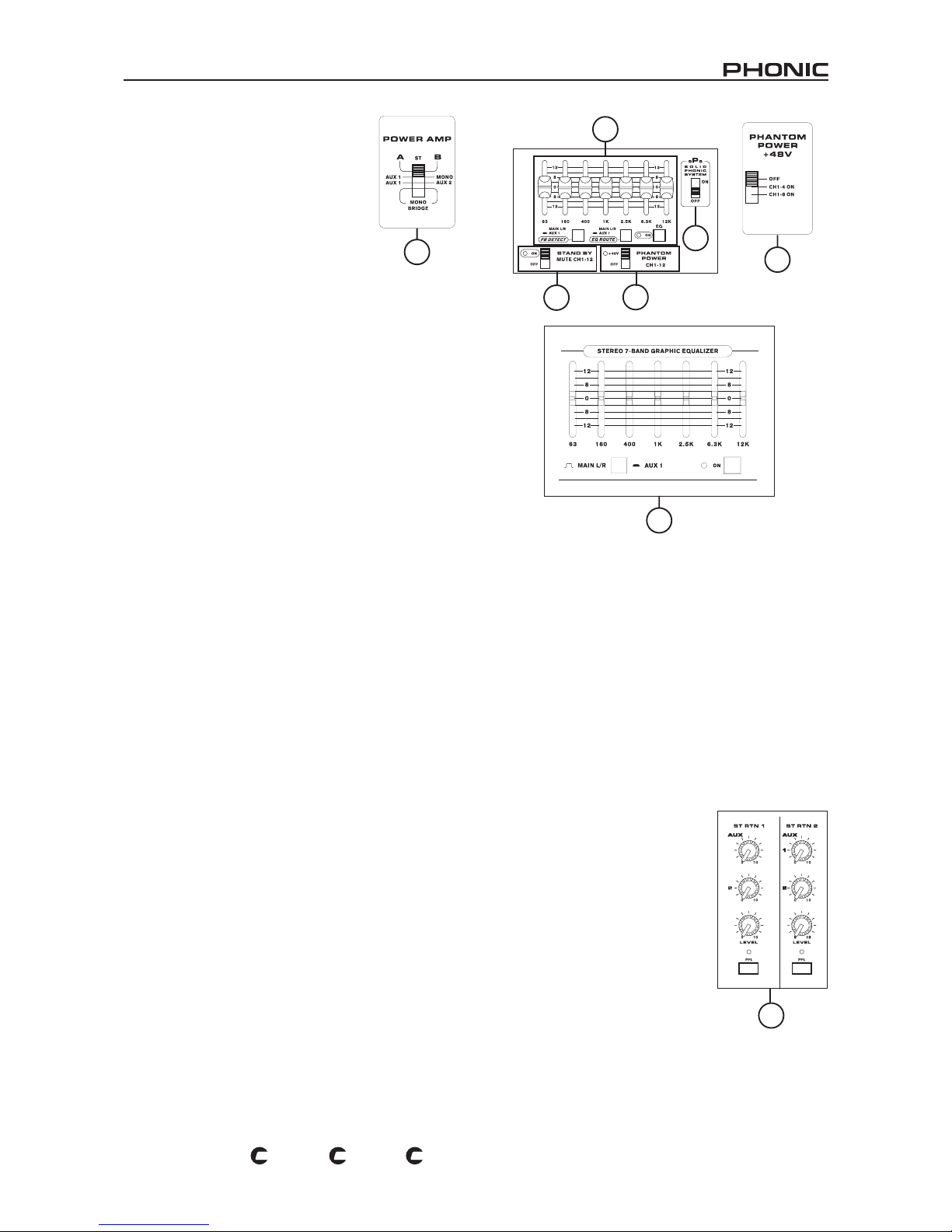
21
POWERPOD 1860 / K-12 / K-16
PL
US
PL
US
PL
US
Sección Principal
46. Interruptores de Control de Amplicador
de Potencia
Estos interruptores controlan la actividad y
fuerza de amplicador de potencia. Usando el
interruptor izquierdo puede alternar entre las
diferentes señales que pueden ser procesadas
por el amplicador de potencia integrado y
ruteadas a las salidas principales de altavoz en
la parte trasera del dispositivo. Este interruptor
le permine seleccionar desde: Estéreo, el
nivel nal del cual es ajustado por fader PRINCIPAL I/D, AUX 1/
MONO, el nivel nal del cual es ajustado por fader AUX 1 y fader
MONO, salidas AUX 1 /AUX 2, el nivel nal del cual es ajutado
por faders AUX 1 y 2 y; MONO BRIDGE, que sale vía salida A
de altavoz profesional solamente y, el volumen es controlado por
el fader MONO.
Nota: Cuando se usa una conexión mono bridge, no conecte
el altavoz a ningún jack auricular 1/4” o conector de altavoz
jack B de altavoz profesional, localizados en el dorso de la
mezcladora.
La potencia de amplicación puede ser cambiada usando el
interruptor derecho desde 100 Watts para cada canal a 300
o 500 Watts por canal en los modelos K-12 Plus y K-16 Plus
solamente, la selección dependerá de tamaño de lugar y la
capacidad de entrada de los altavoces que usted elegió usar.
Esta característica no está icluida en Powerpod 1860 Plus.
47. Sistema de Phonic Sólido (K-16 Plus solamente)
Usando este interruptor (presentado en K-16 Plus solamente)
dará a los usuarios ambas frecuencas alta y baja de su sonido
un poco de incremento para mejorar la robustez del audio en
general. No hay garantía que su sonido mejorará con los sPs
activados, sin embargo, es probablemente deseable escuchar
el sonido de la mezcladora con este interruptor encendido y
apagado y, decide cual es mejor para sus propósitos.
48. Ecualizador Gráco
Este ecualizador gráco de 7 bandas permite a los usuarios
ajustar la respuesta en frecuencia de una señal, con un máximo
de 12dB de realce o corte para cada una de las frecuencias. El
botón AUX 1 / I/D alterna el uso del ecualizador entre las señales
de bus AUX 1 y bus PRINCIPAL I/D. Cuando se selecciona I/D,
el ecualizador es aplicado no solo a ambas señales de estéreo
pincipal(salidas Principal y Altavoz), sino también a la señal
mono. Oprimiendo el botón encendido activa el ecualizador y, es
acompañado por un LED iluminado.
Una característica integrada en el ecualizador gráco de
Powerpod K-12 Plus y K-16 Plus, es el Sistema de Detección
de Retroalimentación. Los LEDs individuales localizados en los
controles deslizante VR de ecualizador se iluminarán cuando
se presente la retroalimentación en esa banda de frecuencia
en particular. Al reducir el nivel de esa banda de frecuencia,
podrá remover efectivamente la retroalimentación en esa
frecuencia.; después de esto, el LED se apagará. Si se oprime
el botón FBD, se activa la detección de retroalimentación para
señal nal AUX 1, mientras que si es liberado, la detección de
retroalimentación es activada para señal PRINCIPAL I-D. Se
recomienda a los usuarios que seleccionen el botón AUX 1 / I/D
en la misma conguración que en el botón de FBD, para así
asegurar ajustes simples en las frecuencias que han producido
retroalimentación.
49. Interruptor Stand-by e Indicador
Este interruptor activa o desactiva el MUTE de los canales de 1 al
15/16 en K-16 Plus, y canales 1 a 11/12 en K-12 Plus y 1860 Plus.
Esta opción es bastante útil para actuaciones en vivo, debido al
hecho de que la Entrada de Tape y Retornos AUX estéreo no
son afectados por ésto, permitiendo que la señal del audio de
reproductor de CD o de otros dispositivos de entrada puedan
reproducirse en las pausas de las presentaciones, mientras se
asegura que los micrófonos no producirán retroalimentación
espantosa de sonido (como opuesto de la retroalimentación
es sonido realmente bueno, por supuesto). Esta opción viene
acompañada de un LED ilumunado.
50. Interruptor de Fuente Fantasma
Cuando este interruptor está en la posición encendido activa una
fuente fatasma de +48V para los canales 1 al 8 en K-12 Plus y,
canales 1 al 12 en K-26 Plus, permitiéndole a los micrófonos
de condensador ser utilizados en estos canales. La activación
de Fuente Fantasma es acompañada por un LED iluminado en
estos dos modelos. En Powerpod 1860 Plus, este interruptor
tiene 3 posiciones, permitiendo a los usuarios activar la fuente
fantasma para los canales de 1 al 8, canales 1 al 4, o ninguno.
51. Controles de Retorno de Estéreo
Estos controles se utilizan para ajustar
el nivel del audio recibido por jacks de
entrada de retorno estéreo. Consisten
en 2 controles de nivel auxiliares, para
ajustar el nivel que será enviado a bus
de mezcla auxiliar y, un control de nivel
para ajustar niveles enviados al bus de
mezcla principal.
Los botones correspondientes PFL
(Pre-Fader Listen) le permiten enviar
el audio de las entradas de retorno
estéreo directamentea control CTRL
RM/PHONES, sin alterarse por ningún
control de nivel. La activación de
PFL está acompañada por un LED
iluminado.
46
48
Powerpod 1860 Plus
48
49
50
47
50
Powerpod
1860 Plus
51
Page 22
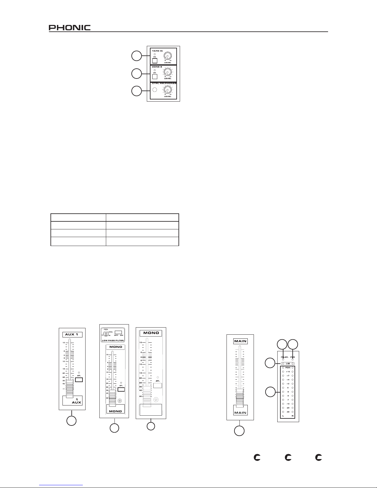
22
POWERPOD 1860 / K-12 / K-16
PL
US
PL
US
PL
US
52. Controles de Entrada de Tape
Este control se utiliza para ajustar
el nivel de entrada de Tape, que
será enviada a la mezcla principal.
El botón PFL (Pre Fader Listen)
correspondiente le permitirá enviar
el audio de la Entrada de Tape al
control CTRL RM/PHONES. En esta
instancia, el Control de Entrada de
Tape no afecta de ninguna manera la
señal enviada al bus PFL/AFL.
53. Controles de Zona 2
Este control se utiliza para ajustar el nivel de la alimentación
de la Zona 2 (duplicado de la mezcla PRINCIPAL I/D) que será
enviada enviada a la salida de Zona 2. El botón AFL (After Fader
Listen) correspondiente le permitirá enviar la alimentación de
audio de la Zona 2 al control CTRL RM/PHONES. La activación
de AFL está acompañada por un LED iluminado.
54. Control de Control Room / Phones
Este botón controla el nivel del audio que se envía a la Salida
CTRL RM/PHONES, localizada en el panel superior de las
mezcladoras K-12 Plus, K-16 Plus y 1860. Cualquier PFL que
sea activado tendrá prioridad sobre todas las otras señales y,
es capaz de correr simultáneamente con otra señal PFL. Si no
se activa ningún PFL, entonces cualquier AFL que sea activado
será utilizado en su lugar (un AFL también puede trabajar
simultáneamente con otro AFLs). También, si no se activa ningún
PFL o AFL, la mezcla PRINCIPAL I/D será usada.
Prioridad de la Alimentación de Control Room / Phones
55. Controles de Auxiliar 1 y 2 (Faders)
Estos controles alteran el nivel de audio que se envía a las salidas
AUX, adecuado para conectar a los monitores de piso, así como
dispositivos de procesamiento externo, si se requieren. Los
botones AFL (After Fader Listen) correspondientes le permiten
enviar el audio del bus de mezcla auxiliar al control CTRL RM/
PHONES, después de ser alterado por el fader correspondiente
(esto es, after-fader). La activación de AFL está acompañada de
un LED iluminado.
56. Controles de Salida Mono
El fader de Canal Mono ajustará el nivel nal del audio que se
envía al jack de salida Mono. El botón AFL (After Fader Listen)
correspondiente le permite enviar la señal de audio mono postfader a control CTRL RM/PHONES.
Los controles correspondientes de Filtro de Paso Bajo, no
presentados en 1860 Plus, son utilizados para reducir sonidos
de frecuencia alta no deseados de la salida mono, a un valor de
18 dB por octava, para un sonido grave más claro cuando se
utilicen subwoofers. El interruptor enciende o apaga el Filtro de
Paso Bajo, mientras que el control que lo acompaña ajusta la
frecuencia de corte mínima entre 60 Hz y 160 Hz.
57. Control de Nivel Principal
Este fader controla el nivel de volumen nal del audio Principal
I/D, que se enviará al amplicador de potencia integrado y las
salidas respectivas.
58. Indicador de Energía
El Indicador de Energía, localizado a un lado del indicador PFL/
AFL, se iluminará cuando la energía de Powerpod K-12 Plus,
K-16 Plus o 1860 Plus está encendida.
59. Indicador PFL/AFL
El indicador PFL/AFL en la parte superior de este medidor es
bicolor, se iluminará en verde cuando un interruptor PFL esté
activado , o se iluminará en rojo para AFL. Debido al hecho
de que cualquier PFL tiene prioridad sobre AFL, si los dos
están activados, solo se iluminará el indicador verde de PFL y
procesado por área de control CTRL RM/PHONES.
60. Indicadores de Limitador
Existen 2 limitadores integrados en amplicador de potencia
estéreo en las Powerpod K-12 Plus, K-16 Plus y 1860 Plus.
Los limitadores se activarán y los indicadores se iluminarán
cuando el nivel de la señal del Amplicador de Potencia se hace
demasiado alto, advertiendo a los usuarios de la posibilidad
de sobrecarga. Si ésto pasa demasiado seguido, asegúrese
de reducir el control de nivel de la entrada correspondiente
para fuente de Amplicador de Potencia, seleccionado por los
interruptores de Control de Amplicador de Potencia a un nivel
razonable.
61. Medidor de Nivel Estéreo
Este medidor de nivel ofrece un display visual de nivel de salida
Principal I/D estéreo. El medidor de nivel de 12 segmentos de
cada canal consiste en LEDs de color verde, amarillo y rojo,
incluyendo un indicador de pico, mostrando niveles entre -30dBu
y +10dBu. Cuando ningún PFL o AFL está activado, el medidor
de nivel principal ofrece un display visual de nivel de la señal
de PFL o AFL, monitoreado en los mismos aspectos que en
situaciones normales. Vea la sección Control Room/Phones (54)
para un poco más de información en PFLs y AFLs.
52
53
54
55
56
56
Powerpod 1860 Plus
57
60
61
59 58
Prioridad Alimentación
Más Alta PFL
Media AFL
Más Baja PRINCIPAL I/D
Page 23
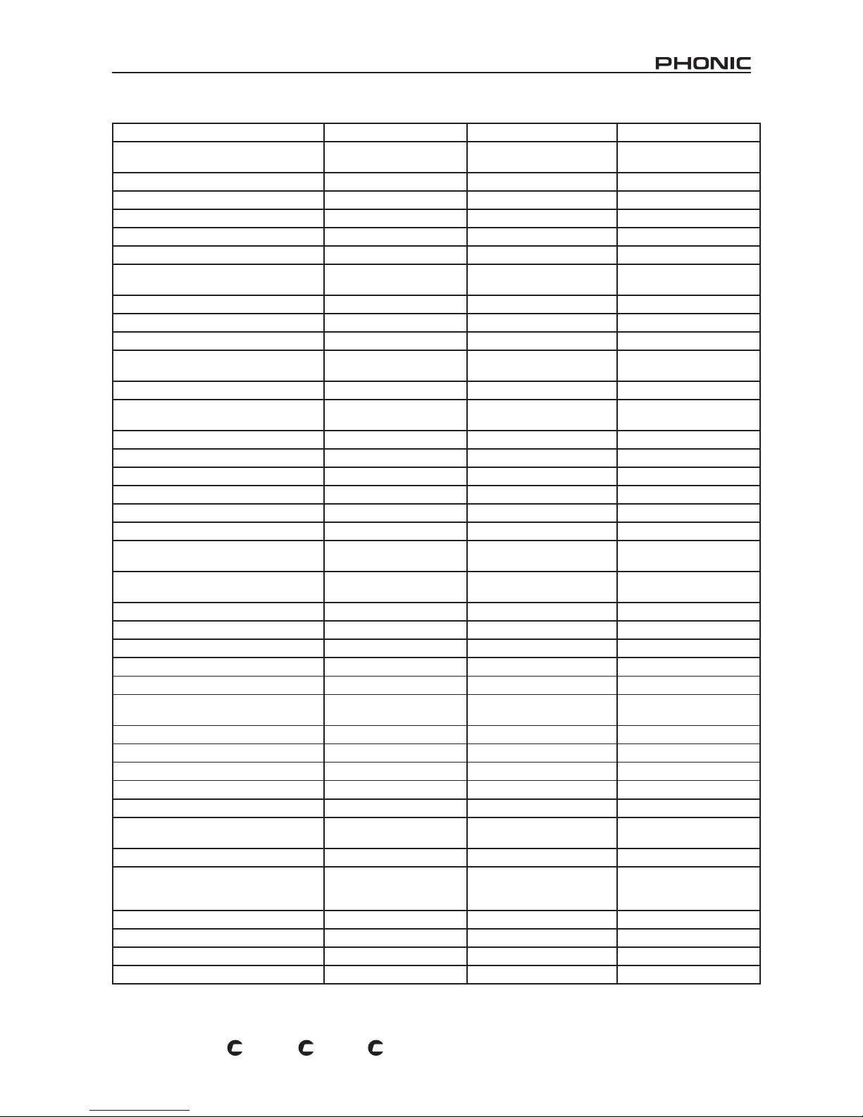
23
POWERPOD 1860 / K-12 / K-16
PL
US
PL
US
PL
US
ESPECIFICACIONES
POWERPOD K-12 Plus POWERPOD K-16 Plus POWERPOD 1860 Plus
AMPLIFICADOR DE POTENCIA, energía
de salida en Watts @ THD < 0.5%, 1KHz
Número de Canales de Energía 2 2 2
Limitadores 2 2 2
8 ohms por Canal 330 330 260
4 ohms por Canal 500 500 400
8 ohms Bridge Mono 1000 1000 800
Interruptor de Selección de Amp. de
Potencia
500W+500W, 300W+300W,
100W+100W
500W+500W, 300W+300W,
100W+100W
N/A
Entradas
Canales totales 10 14 10
Canales Balanceados Mono de Mic/Línea 8 (XLR + 1/4” combo jack) 12(XLR + 1/4” combo jack) 8 (XLR + 1/4” combo jack)
Canales de Línea Estéreo con
preamplicador de mic
2 (XLR & 2x 1/4”) 2 (XLR & 2x 1/4”) 2 (XLR & 2x 1/4”)
Retornos Aux Estéreo 2 2 2
Entrada 2T
1 (1 x Mini estéreo & 2x
RCA jacks)
1 (1 x Mini estéreo & 2x RCA
jacks)
1 (1 x Mini estéreo & 2x
RCA jacks)
Salidas
Estéreo Principal I/D 2 x 1/4” TS, Desbalanceada 2 x 1/4” TRS, Desbalanceada 2 x 1/4” TS, Desbalanceada
Mono Principal 1/4” TS, Desbal. 1/4” TRS, Desbal. 1/4” TS, Desbal.
Envío Aux & Envío de Efecto 4 x 1/4” TS, Desbalanceado 4 x 1/4” TRS, Desbalanceado 4 x 1/4” TS, Desbalanceado
Phones 1 1 1
Salida Control RM o Zona 2 2 x 1/4” TS, Desbalanceado 2 x 1/4” TRS, Desbalanceado 2 x 1/4” TS, Desbalanceado
Salida Rec
1 x Mini estéreo, 2 x RCA
jacks
1 x Mini estéreo, 2 x RCA
jacks
1 x Mini estéreo, 2 x RCA
jacks
Salida de Altavoz
1 x Speakon & 2 x 1/4” TS
por canal
1 x Speakon & 2 x 1/4” TRS
por canal
1 x Speakon & 2 x 1/4” TS
por canal
Tiras de Canal 10 14 10
Control Aux 4 4 4
Control de Balanceo/Paneo Sí Sí Sí
On/Mute de Canal Sí Sí Sí
Canal Solo/PFL con medición Sí Sí Sí
Indicadores LED
Encendido, Pico, Señal,
PFL
Encendido, Pico, Señal, PFL
Encendido, Pico, Señal,
PFL
Controles de Volumen 60 mm faders 60 mm faders 60 mm faders
Insert Sí Sí Sí
Sección Principal
Envíos Aux Principales 2, 60mm fader 2, 60mm fader 2, 60mm fader
Retorno de Efectos a Monitor 4 4 3
Control de nivel audífonos/control RM/
Zona 2
Sí Sí Sí
Modo de Control Room ST, PFL/AFL ST, PFL/AFL ST, PFL/AFL
Faders
2 x Efx, Aux 1, Aux 2,
Mono, Principal I/D (60mm
fader)
2 x Efx, Aux 1, Aux 2, Mono,
Principal I/D (60mm fader)
2 x Efx, Aux 1, Aux 2,
Mono, Principal I/D (60mm
fader)
Mediciones
Número de Canales 2 2 2
Segmentos 13 13 13
Suministro de Fuente Fantasma +48 V DC +48 V DC +48 V DC
Page 24
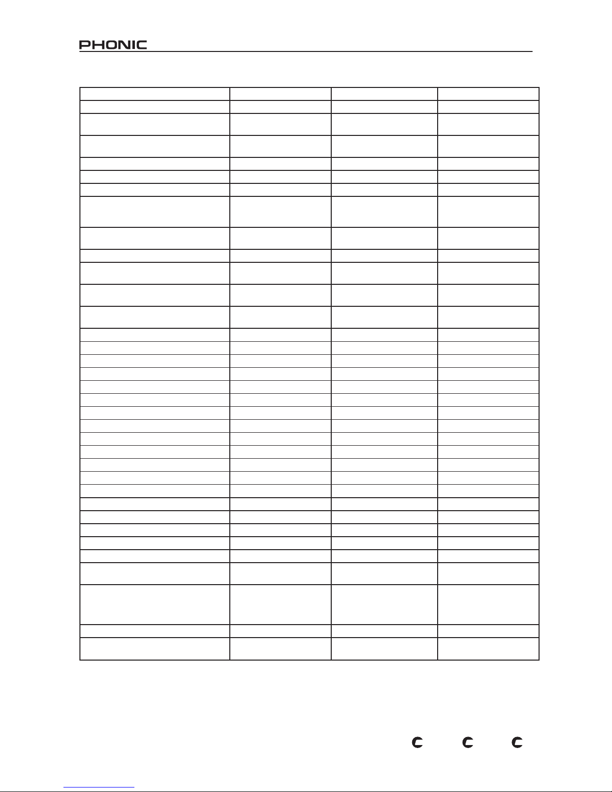
24
POWERPOD 1860 / K-12 / K-16
PL
US
PL
US
PL
US
Interruptor Principal +10 Principal +10 Principal +10
THD
Salida de energía, 1 KHz, 20Hz a 20 kHz
@250 Watts, 4 ohms <
0.5%
@250 Watts, 4 ohms < 0.5%
@250 Watts, 4 ohms <
0.5%
Cualquier salida, 1kHz @ +14dBu, 20Hz a
20 kHz, entradas de canal
< 0.3 % < 0.3 % < 0.3 %
CMRR
1 kHz @ -60dBu, Ganancia al máximo 80 dB 80 dB 80 dB
Crosstalk
1kHz @ 8dBu, 20Hz a 20 kHz ancho
de banda, entrada de canal a salidas
principales I/D
Fader de canal bajo, otros canales en
unidad
<-63 dB <-63 dB <-63 dB
Canal en mute, otros canales en unidad <-64 dB <-64 dB <-64 dB
Respuesta en Frecuencia (entrada mic
a salida)
20Hz~20kHz, nivel de línea o/p @ +4dBu
en 600 ohms
+0/-2 dB +0/-2 dB +0/-2 dB
20Hz~20kHz, amp de potencia o/p 1 watt
en 8 ohms
+0/-2 dB +0/-2 dB +0/-2 dB
Nivel Máximo
Entrada de Preamp Mic +10 dBu +10 dBu +10 dBu
Todas las Otras Entradas +22 dBu +22 dBu +22 dBu
Salidas Desbalanceadas +22 dBu +22 dBu +22 dBu
Impedancia
Entrada Mic 5K ohms 5K ohms 5K ohms
Entrada Línea 50K ohms 50K ohms 50K ohms
Todas Otras Entradas (excepto inserts) 10K ohms 10K ohms 10K ohms
Salidas RCA 2T 600 ohms 600 ohms 600 ohms
Todas Otras Salidas 150 ohms 150 ohms 150 ohms
Ecualización 3 bandas, ±15dB 3 bandas, ±15dB 3 bandas, ±15dB
EQ Bajo 80 Hz 80 Hz 80 Hz
EQ Medio 100-8K Hz, barrible 100-8K Hz, barrible 2.5 KHz
EQ Segundo Medio (canal St) 2.5 KHz 2.5 KHz 2.5 KHz
EQ Agudo 12 KHz 12 KHz 12 KHz
Filtro de Corte Bajo 75Hz(-18dB/oct) 75Hz(-18dB/oct) 75Hz(-18dB/oct)
Preamplicador de Micrófono E.I.N.
150 ohms terminado, ganancia máxima <-122 dBm <-122 dBm <-122 dBm
Consumo de Energía (Máximo
Promedio)
500 Watts 500 Watts 400 Watts
Energía Requerida
100 -120 VAC, 220240 VAC, 50/60 Hz,
dependiendo de la
conguración regional
100 -120 VAC, 220-240 VAC,
50/60 Hz, dependiendo de la
conguración regional
Intercambiable entre
115VAC & 230VAC, 50/60
Hz
Peso Neto 14.5 Kg (31.9 lbs) 19.5 Kg (13.0 lbs) 14.3 Kg (31.5 lbs)
Dimensiones (An x Al x P)
483 x 142.6 x 466.2 mm
(19” x 5.6” x 18.4”)
583.2 x 142.6 x 466.2 mm
(23” x 5.6” x 18.4”)
448 x 147 x 465 mm
(17.6” x 5.8” x 18.3”)
Page 25
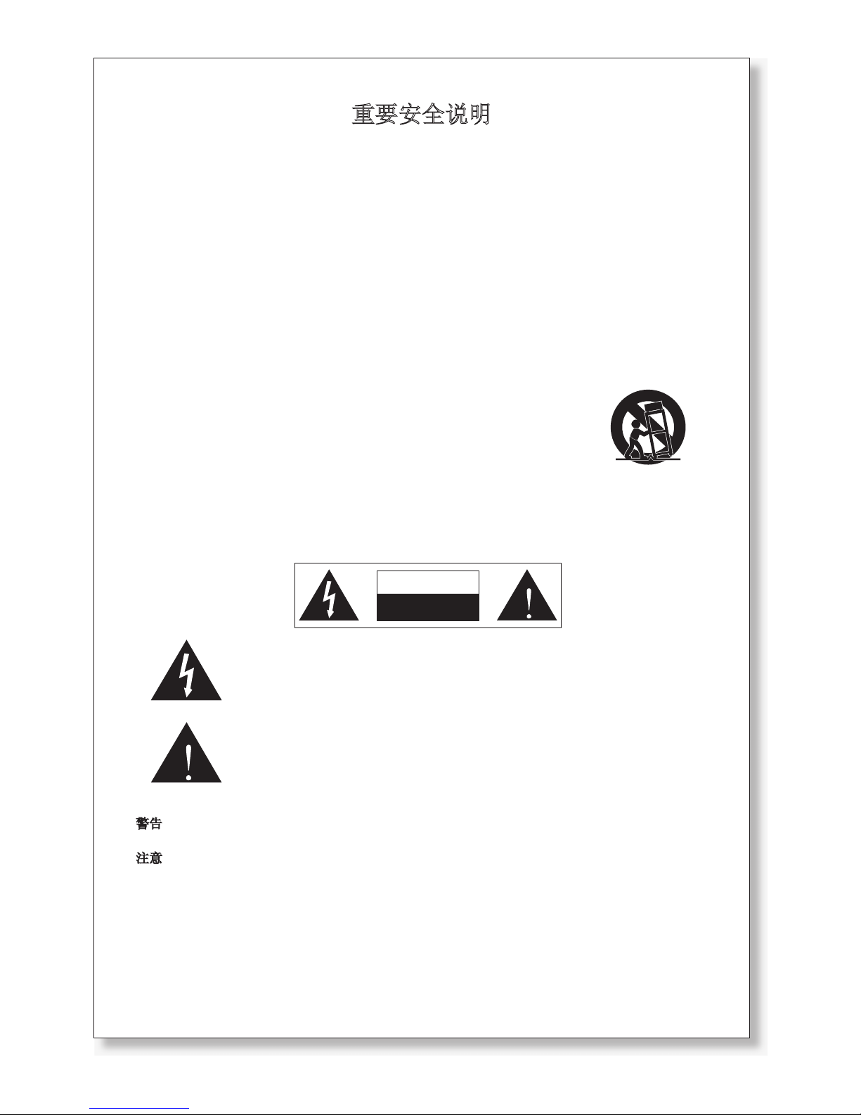
重要安全说明
1. 请在使用本机前,仔细阅读以下说明。
2. 请保留本使用手册,以便日后参考。
3. 为保障操作安全,请注意所有安全警告。
4. 请遵守本使用手册内所有的操作说明。
5. 请不要在靠近水的地方,或任何空气潮湿的地点操作本机。
6. 本机只能用干燥布料擦拭,请勿使用喷雾式或液体清洁剂。清洁本机前请先将电源插头拔掉。
7. 请勿遮盖任何散热口。确实依照本使用手册来安装本机。
8. 请勿将本机安装在任何热源附近。例如:暖气、电暖气、炉灶或其它发热的装置(包括功率
扩大机)。
9. 请注意极性或接地式电源插头的安全目的。极性电源插头有宽窄两个宽扁金属插脚。接地式
电源插头有两支宽扁金属插脚和第三支接地插脚。较宽的金属插脚(极性电源插头)或第三支
接地插脚(接地式电源插头)是为安全要求而制定的。如果随机所附的插头与您的插座不符,
请在更换不符的插座前,先咨询电工人员。
10. 请不要踩踏或挤压电源线,尤其是插头、便利插座、电源线与机身相接处。
11. 本机只可以使用生产商指定的零件/配件。
12. 本机只可以使用与本机搭售或由生产商指定的机柜、支架、三脚架、拖架
或桌子。在使用机柜时,请小心移动已安装设备的机柜,以避免机柜翻倒
造成身体伤害。
13. 在雷雨天或长期不使用的情况下,请拔掉电源插头。
14. 所有检查与维修都必须交给合格的维修人员。本机的任何损伤都须要检修,例如: 电源线或插
头受损,曾有液体溅入或物体掉入机身内,曾暴露于雨天或潮湿的地方,不正常的运作,或曾
掉落等。
这个三角形闪电标志是用来警告用户,装置内的非绝缘危险电压足以造成使人触
电的
危险性。
这个三角形惊叹号标志是用来警告用户,随机使用手册中有重要操作与保养维修
说明。
警告: 为减少火灾或触电的危险性,请勿将本机暴露于雨天或潮湿的地方。
注意: 任何未经本使用手册许可的操控,调整或设定步骤都可能产生危险的电磁幅射。
CAUTION
RISK OF ELECTRIC SHOCK
DO NOT OPEN
PHONIC CORPORATION
Page 26
26
POWERPOD 1860 / K-12 / K-16
PL
US
PL
US
PL
US
简介
感谢您购买Phonic的 Powerpod K-12 Plus,Powerpod K-16
Plus或Powerpod 1860 Plus 功放调音台。此系列产品品质优良,
绝对是您物超所值的选择。为了确保您最佳的使用本产品,请仔
细阅读使用手册,读完后请妥善保管,以备日后查阅。
特色
• 可切换的电源供应减轻机身重量
•
脚踏开关可开启/静音效果处理器和节拍延迟控制
• +48V
幻象电源开关
•
两个立体输入声道含3段EQ
•
录音输入和录音输出的立体RCA插孔
•
2路推杆前AUX输出和2路推杆后EFX输出
•
立体7段图形均衡
•
每通道一个专用音箱连接器和两个1/4" TS phone 型插孔用于
音箱连接
•
旁通功能可对所有麦克风声道静音
•
连接式手把
•
低通滤波器的单通道Mono输出,60Hz-160Hz内的可变频率
•
特制保护层封盖防止机器表面刮损
• 115VAC
和230VAC可切换主电源
Powerpod K-12 Plus 和 Powerpod K-16 Plus
• 2 X 500W/4Ω桥接式和修补式功率放大器
•
两个效果处理器具100种效果, 节拍延迟和多种测试音调
•
回授检测系统
• Powerpod K-12 Plus
• 8 路麦克风/高电平声道含3段扫频中频EQ和插入点
• Powerpod K-16 Plus
• 12路麦克风/高电平声道含3段扫频中频EQ和插入点
•
卡拉OK消音器
•
音箱扩音系统
Powerpod 1860 Plus
• 2 X 400W/4Ω桥接式和修补式功率放大器
•
一个效果处理器具100种效果, 节拍延迟和多种测试音调
• 8
路麦克风/高电平输入声道含3段EQ和插入点
•
双重设定的幻象电源开关
基本安装
开始设定
1、确保关闭所有电源,断开AC电源连接线。
2、将所有音量推杆和音量控制调至最低,关闭所有声道,以确
保开启时输出端口不会产生噪音。打开调音台之后,再将音
量调到理想位置。
注意:调音台后侧与墙壁应相隔30厘米以上,否则不利于通
风,将造成系统过热。
3、将所需乐器和设备接入相应的输入端口,如吉它,麦克风,
电子琴,信号处理器等。
4、将所需设备接入相应的输出端口,如音箱,监听器,录音设
备和信号处理器。
注意:只有音箱才能与功率放大器输出端口相连接。不正当
将设备连接至调音台将造成设备损伤。请勿使用吉它连接线
连接放大器和音箱。
5、将AC电源线插入设备后侧的AC电源插孔,并确保电压与当地
额定电压一致。可将Powerpod 1860 Plus 的电压选择设置成
当地额定电压。
6、将AC电源线接入适配的电源输出端口。
7、打开电源。
声道设置
1、为获得准确的音量输出,请将所有声道关闭并将音量推杆设
置为0。
2、选择连接的声道,确保输出信号与输入信号一致,可通过试
听麦克风或弹奏乐器判断信号是否正常传送。
3、按下声道的PFL按钮,可看到主电平表的音量显示。
4、调节增益,使得电平表的显示为0dB。
5、声道设置完成,可停止测试信号。
6、使用声道前请先释放PFL按钮再打开声道开关。
7、按以上步骤设置其它声道。
Page 27
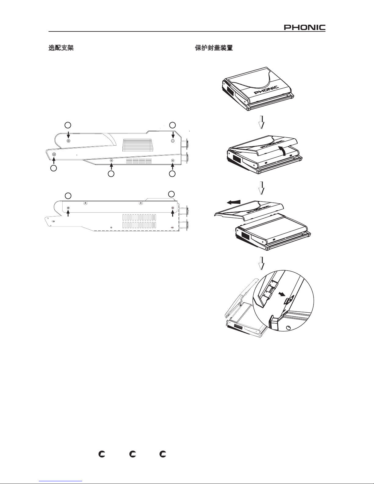
27
POWERPOD 1860 / K-12 / K-16
PL
US
PL
US
PL
US
选配支架
1、Powerpod K-12 Plus和Powerpod 1860 Plus 都可固定于
Phonic的 ER K-12 Plus支架上,只需13U的支架空间即可架
设。
2、确保支架可提供良好的通风空间,为避免系统过热请勿使用
密封支架,调音台与其它设备间的间距应保证在1U以上。
3、旋开调音台两边的螺丝① ~ ⑤和侧面板。
4、将支架固定于调音台两侧,旋紧螺丝⑥ ~ ⑦。
5、最后把调音台置于支架上。
保护封盖装置
1 2
3
4
6
7
5
打开封盖
Opening the cover
移除封盖
Removing the cover
固定封盖
Attaching the cover
按下两个凸起部位打开
Place your ngers on the
two extrusioins and pull
up to open.
把封盖的连接部位固定在调
音台的卡榫扣上
Place the small connecting
rods of the molded cover
und e r n e a th the mixer's
hooks.
Page 28
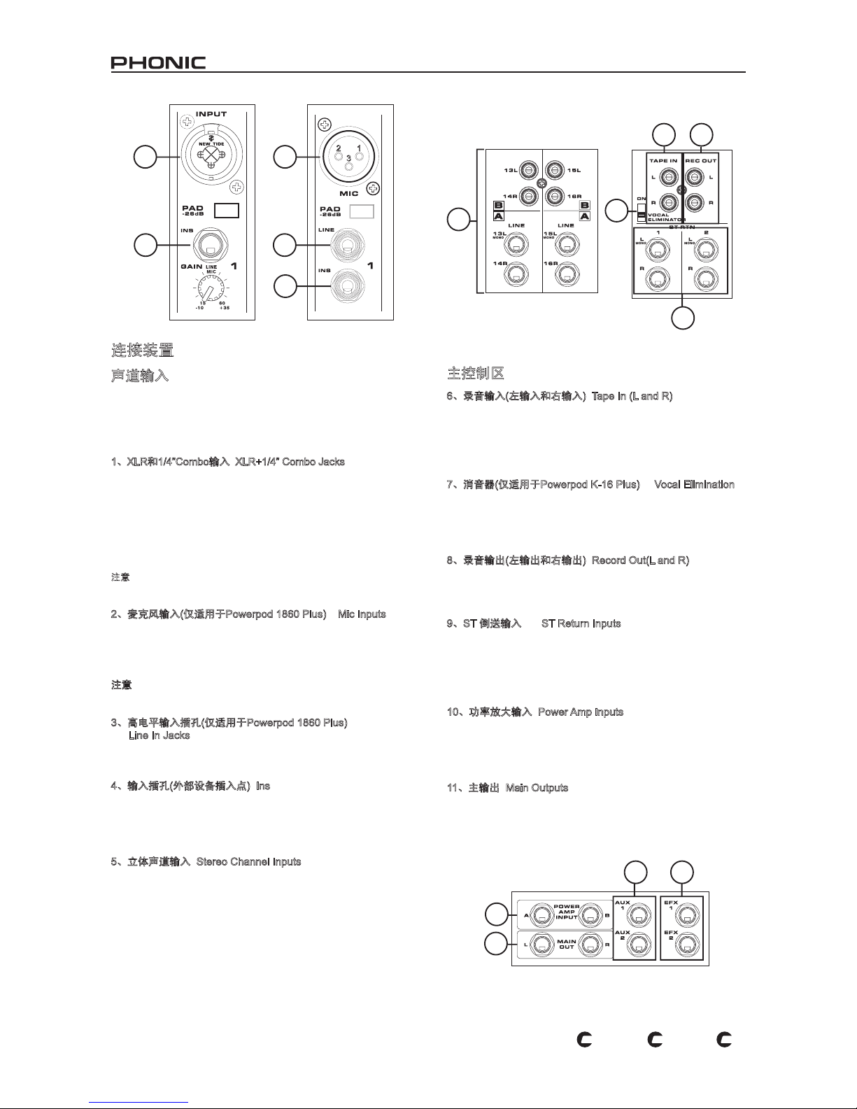
28
POWERPOD 1860 / K-12 / K-16
PL
US
PL
US
PL
US
连接装置
声道输入
Powerpod K-12 Plus和Powerpod 1860 Plus各有10路输入声道,其
中两路可接收立体信号。Powerpod K-16 Plus设有14路输入声道,
其中两路可接收立体信号。每立体声道含有不同的输入插孔,可连
接RCA或1/4”耳机插头。
1、XLR和1/4”Combo输入 XLR+1/4” Combo Jacks
Combo接口可接收XLR或1/4” 输入的平衡式和平衡式信号。可连
接专业电容式麦克风,动力型或铝带式麦克风;连接标准的XLR
阳性连接器,以及用于连接各种乐器,如电吉它,电子琴,鼓声产
生器等等典型1/4” TRS和1/4” TS高电平输入。这些输入经前置放
大处理,可为您带来高保真,水晶般清丽的音质。
PAD - 2 6dB按钮位于Com b o接口的正下方, 可对输入信号进行
26dB的削减。此功能只适用于高电平输入设备。
注意: 使用非平衡 式麦克风时 ,请确 保关闭幻象 电源。使用 电容式 麦克
风,应开启对应声道的幻象电源。
2、麦克风输入(仅适用于Powerpod 1860 Plus) Mic Inputs
Powerpod 1860 Plus不具备上面提及的Combo插孔,采用了独
立的XLR和1 /4”插孔,使得XLR麦克风输入可接收平衡式和非平
衡式信号。可连接专业电容式,动力型和铝带式麦克风。经前置
放大处理后,可为您带来高保真,水晶般清丽的音质。
注意:使用非平衡式麦克风时,请确保关闭幻象电源。 使用电容
式麦克风,应开启对应声道的幻象电源。
3、高电平输入插孔(仅适用于Powerpod 1860 Plus)
Line In Jacks
这些输入可连接1/4”TRS和1/4” TS高电平输入,用于额外的多种
乐器,如电吉它,电子琴,鼓声产生器,以及其它的电子乐器。
4、输入插孔(外部设备插入点) Ins
这些TRS耳机型插孔最主要的作用是将额外的外部装置,如均衡
器或动力处理器,连接至对应的单通道Mono输入声道。使用Y型
线可将调音台的信号传送至外部处理器,将外部处理器的信号输
往调音台。想知道更多有关于Y型线的资讯,请参考附录C。
5、立体声道输入 Stereo Channel Inputs
Powerpod K-12 Plus,Powerpod K-16 Plus和Powerpod 1860
Plus 调音台各含2个立体声输入声道,与单通道Mono输入略有不
同。立体RCA输入可连接外部多种数字设备(CD播放器,MP3播
放器,手提型电脑等),2个高电平1/4”TS插孔可连接外部多种高
电平输入设备,如电子琴。可根据您使用的输入设备,将声道的
立体A/B钮设在适当的位置。
如果您想将非立体声设备接入立体输入,只需简单地将设备的
1/4”耳机插孔插入左(单通道Mono )立体输入,将右边的输入插孔
空出来。
1
4
2
3
4
6
7
9
8
5
主控制区
6、录音输入(左输入和右输入) Tape In (L and R)
这些输入 插 孔 可 连 接 经 R CA接线的 磁 带 和 C D播 放 器 。 除 此
之外 ,Ph o ni c还设 有一个 迷你立 体输入 端口 ,连接 迷你唱 片
disc(MD),便携式CD,MP3播放器(如苹果Apple iPod),以及手
提型电脑。此输入信号在输往Main L/R混音总线前,将直接输送
至录音输入Tape In混音总线。
7、消音器(仅适用于Powerpod K-16 Plus) Vocal Elimination
打开Powerpod K-16 Plus的这一开关,可消除任何从CD或磁带
播放器输往录音输入 Tape In 的信号。使用左右声道间的音频频
率相位消除,Po wer pod K-16 Plus的消音功能可有效的消除音
场。
8、录音输出(左输出和右输出) Record Out(L and R)
与录音输入端子相似,这些输出可经RCA连接线连接各种录音设
备。此外还包括迷你立体端子,连接MD播放器和手提电脑等附
加录音设备。
9、ST 倒送输入 ST Return Inputs
这些T S输入可将并联 外部设备接入调音台,如辅助调音台或 外
部效果 处理器,接收其它声源处理过的信号, 然后输送至AUX
1,AU X 2和Mai n L/R混音总线。如果您想将非立体声设备接入
立体倒送输入,只需简单地将设备的1/4 ”耳机插孔插入左(单通道
Mono)立体输入,将右边的输入插孔空出来。
10、功率放大输入 Power Amp Inputs
这些输入可连接1/4”TS插头,将外部高电平立体信号输往内建功
率放大器。若将一设备接入功率放大输入,主输入(参考功率放大
开关)将自动旁通功率放大,插入的输入将被放大,并输往音箱输
出。
11、主输出 Main Outputs
这两个端子可输出主混音总线的最终立体高电平信号。这些插孔
的主要的作用是将主输出M ain Out put的信号输送至与调音台并
联的外部设备,如调音台,PA系统,功率放大器,以及其它一系
列的信号处理器。
10
11
12
13
Page 29
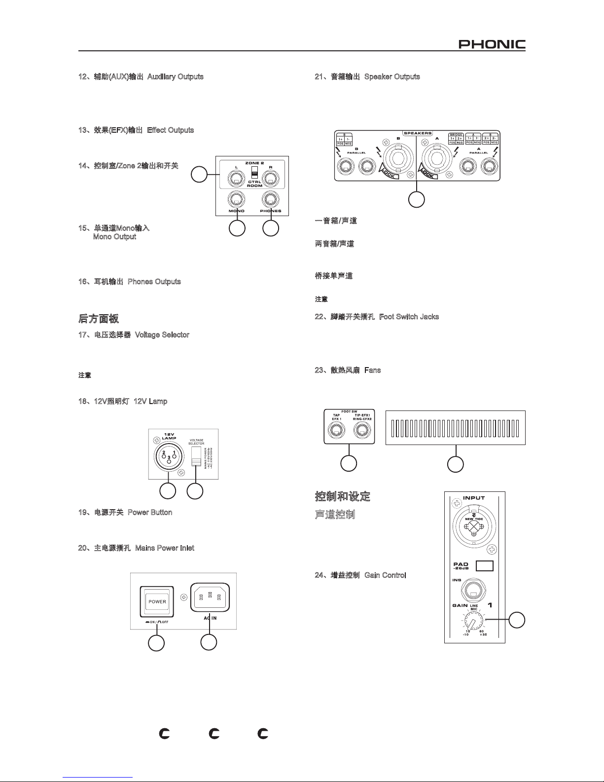
29
POWERPOD 1860 / K-12 / K-16
PL
US
PL
US
PL
US
12、辅助(AUX)输出 Auxiliary Outputs
这些耳机插孔可输出相应辅助混音总线的最终高电平信号,极其
适用于舞台监听。将辅助输出的信号输往功率放大器,或均衡
器,然后输送至地面监听音箱,使得音乐家可对乐器和声音进行
监听。
13、效果(EFX)输出 Effect Outputs
这些1/4”TS输出可输送效果EFX输入混音总线的最终输出信号。这
些输出可根据您的需要连接外部数字效果处理器,或功放和音箱。
14、控制室/Zone 2输出和开关
这些耳 机插孔输出可输入控制室
或Z on e 2控制 面板的 信 号。 对
应的开关可在控制室/耳机C T R L
RM/PHONES和Zone 2控制间切
换输入。
15、单通道Mono输入
Mono Output
这个1/4 ”TS输出可输入主混音面板上的单通道Mon o混音控制的
音频信号。适用于单通道Mono音响系统,音箱的超低音单元以
增加低音音效。
16、耳机输出 Phones Outputs
这个立体输出端口可连接头戴式耳机,可对混音进行监听。可通
过控制室/耳机CTRL RM/PHONES控制调节输出音量。
后方面板
17、电压选择器 Voltage Selector
此开关可在两个主电源模式间进行选择,115VAC/60Hz (可在额
定电压为100~120V的地区使用)或230VAC/50Hz(可在额定电压为
200~230V的地区使用)。
注意:使用不正确的电压将对调音台造成严重的损害,选择电压时请务必
核对当地的额定电压。若不确定当地电压,请查询相关资讯。
18、12V照明灯 12V Lamp
这个XLR端子可连接12V鹅颈型电灯,以利于在光线阴暗处正常
操作。
19、电源开关 Power Button
此按钮可控制调音台的开关。开启电源开关前,请将所有的音量
控制调节至最小值。
20、主电源插孔 Mains Power Inlet
此端子可连接AC电源线的一端。另一端应接入适当的电源供应器。
21、音箱输出 Speaker Outputs
这些插孔可连接音箱,传送内置功率放大器的信号。第一组输出
端口为专业的音箱连接器;将适当的四芯插头插入连接器,并拧
紧即可使用。第二组输出端口为1/4 ”耳机插孔;将适当的1/4”TS
插头插入即可使用。音箱的总阻抗应小于4ohms/声道,桥接单通
道应小于8ohms。
一音 箱 /声道 : 将单个 音 箱接入 各 声道的输 出,可使 用阻抗为
4~8ohms的音箱。适用于耳机插孔和专业音箱连接器。
两音箱/声道:将两个音箱接入音箱输出端口,各音箱的阻抗应为
8~16ohms(两个8ohm音箱的阻抗为4ohms,两个16ohm音箱的阻
抗为8ohms)。
桥接单声道:桥接单通道时,只可使用专业音箱输出A。总阻抗
不得小于8ohms。
注意:只可将有源音箱接入音箱输出,以免对设备造成严重损伤。
22、脚踏开关插孔 Foot Switch Jacks
这两个端子可连接脚踏开关,远程控制内建数字效果处理器。左
插孔可进行节拍延时 控制,右插孔可开关数字效果控 制(仅适用
于Powerpod K-12 Plus和Powerpod K-16 Plus的数字效果处理器
2)。
23、散热风扇 Fans
这些变速风扇可冷却调音台。使用中请保持散热口通畅,否则,
将造成系统过热。
14
15 16
18
17
19
20
21
22
23
24
控制和设定
声道控制
未使用时,所有的声道都是独立的不
起任何作用。打开声道前请先调低相
应声道的音量;开启后再将音量控制
调节到适当大小。
24、增益控制 Gain Control
此旋钮可调节输入信号的灵敏度,输
往相应的输入声道。增益控制应在对
音量进行最佳调节的同时保证输入音
质,即峰值指示灯偶尔闪亮。
Page 30
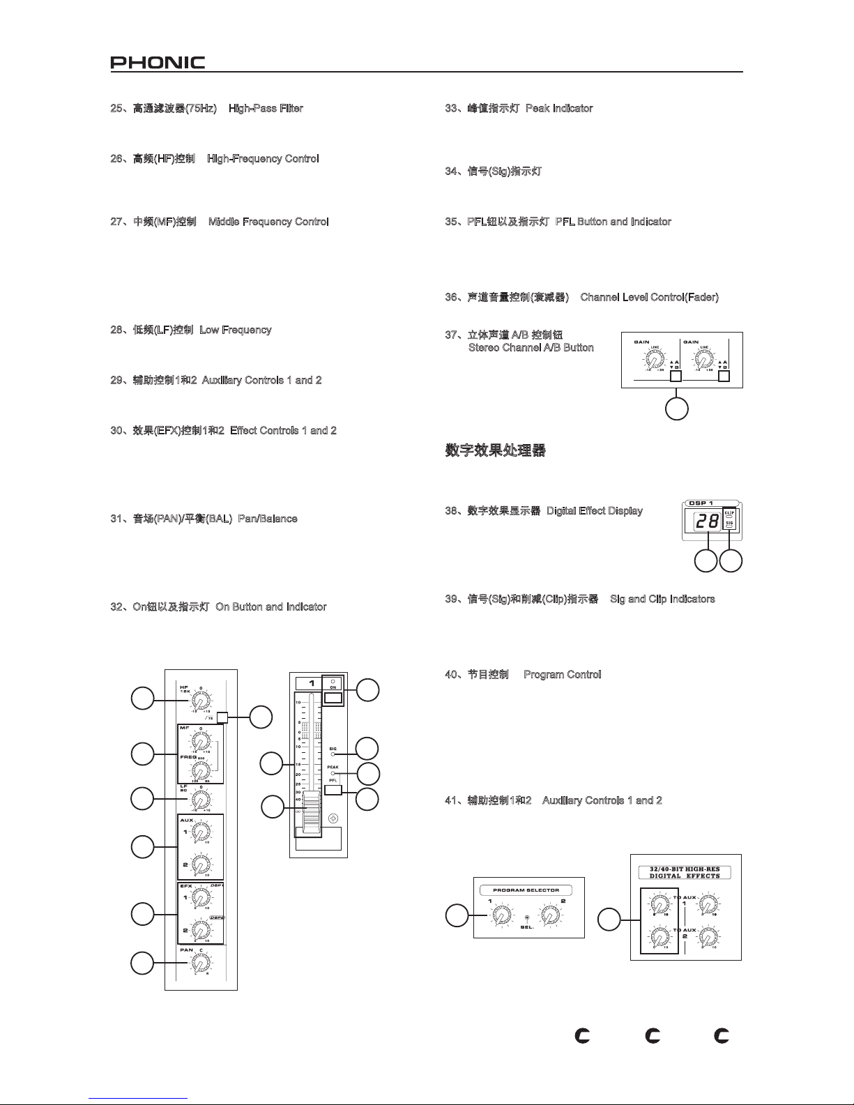
30
POWERPOD 1860 / K-12 / K-16
PL
US
PL
US
PL
US
25、高通滤波器(75Hz) High-Pass Filter
按下 此按钮 即可 打开高 通滤波 器,可 对7 5H z以下 的频率 进行
18dB/oct的削减,可消除地面噪音或舞台隆隆声。
26、高频(HF)控制 High-Frequency Control
此旋钮可对高频进行1 5dB的增强或削减,可调节声音的高频部
分,增加钹,吉它,合成器和Michael Jackson等声音的力度和劲
道。
27、中频(MF)控制 Middle Frequency Control
此控制可对中频进行15dB的增强或衰减调节。Pow erpod K-12
Plus和Powerpod K-16 Plus的单通道Mono可进行扫频控制,可
在100Hz和8Hz间选择中间频率。Powerpod 1860 Plus的所有声
道中间频率为2.5kHz。
要调节中频并非易事,人们通常希望对中频进行削弱而非增强,
缓和音频中刺耳的人声和乐器声。
28、低频(LF)控制 Low Frequency
此旋钮可对低频(80Hz)进行15dB的增强或削减,可调节声音的低
频部分,柔和并增加鼓,低音电吉它和Isaac Hayes等的力道。
29、辅助控制1和2 Auxiliary Controls 1 and 2
这些旋钮可调节输入辅助1和2混音总线的信号的音量,可连接舞
台监听器。
30、效果(EFX)控制1和2 Effect Controls 1 and 2
这些旋钮可调节输往效果1和2输出的信号的音量,可连接外部信
号处理器(经立体倒送输入可返回调音台),或用作所需设备的额
外辅助输出。这些旋钮还可调节输往内建数字效果处理器的信号
的音量(Powerpod 1860 Plus的EFX 2可调节输往内建效果处理器
的信号的音量)。
31、音场(PAN)/平衡(BAL) Pan/Balance
此旋钮 用 于 调 节 主 混音左右 两 边 接 收 信 号的大小。 经 单 通 道
Mon o,此旋钮可控制左右音场的音量。经立体声道,则可对左
右两边的音频信号进行削弱,以达到平衡控制。
声道未开启时,PFL仍可将声道信号输往控制室/耳机CTRL RM/
PHONES混音总线进行监听。
32、On钮以及指示灯 On Button and Indicator
打开按钮,即可将声道输入信号传送至Main L/ R,Mono,AUX
1和2,EFX1和2总线。开启时相应的指示灯也将变亮。
33、峰值指示灯 Peak Indicator
当信号接近峰值还差6d B前,快要产生削波失真时,LE D峰值指
示灯将变亮。建议调节声道增益以减少峰值指示灯的闪动的次
数。
34、信号(Sig)指示灯
声道的信号达到- 20dB时,相应的LED指示灯将变亮,指示输往
输入声道的信号。
35、PFL钮以及指示灯 PFL Button and Indicator
PFL(Pre -Fa der-List en)推杆前监听按钮可监听对应声道输至控
制室/耳机CTRL RM/PHONES控制(推杆前,推杆后)的信号,使
用耳机监听或舞台监听。PF L开启时相应的绿色LED指示灯将闪
亮。
36、声道音量控制(衰减器) Channel Level Control(Fader)
此控制可调节对应声道输往主混音总线的信号的音量。
37、立体声道 A/B 控制钮
Stereo Channel A/B Button
释放此 按 钮 , P ow er p o d K -1 2
Pl u s,P o we r po d K- 1 6 P lu s,
Powerpod 1860 Plus对应立体声道
将接收1 / 4 ”输入的信号;按下此按
钮,立体声道将接收对应立体RCA
输入的信号。
数字效果处理器
Powerpod K-12 Plus和Powerpod K-16 Plus设有两个效果声道,
Powerpod 1860 Plus只有一个。
38、数字效果显示器 Digital Effect Display
这个2位数字显示器可显示当前应用于EFX效果的
节目的数值。当切换节目时,可滚动显示节目数
值。如果数秒内不进行节目选择,显示值将回复
至原节 目。其它的功能,请参考附录A数位效 果
表。
39、信号(Sig)和削减(Clip)指示器 Sig and Clip Indicators
位于数位效果显示区,在效果处理器接收信号时,S i g信号指示
灯将变亮,当超强信号突然回还前Cl i p削减指示灯将变亮。如果
Cl ip削减指示灯频繁闪亮时,请将一个或所有的EFX控制关小,
以免信号音量过高。
40、节目控制 Program Control
此旋钮用于滚动各种效果。顺时针旋转,可调节较高的节目数
值,逆时针旋转可调节较低的节目数值。切换新节目时,LED指
示灯将闪亮。按此按钮将用于新功能。选择节拍延时效果时,按
此按钮可选择延长节拍的时间。多次按此按钮,效果处理器将记
忆最后两次按动间的时间间隔,记录为延长时间,直至下次按钮(
即使断电,操作仍将保存)。选择节拍延时效果时,数位效果显示
面板上的小LED灯将以选择间隔闪动。欲知可用的节目表,请参
考附录A数字效果表。
41、辅助控制1和2 Auxiliary Controls 1 and 2
这些旋钮可调节对应数字效果处理器输往对应辅助混音总线的信
号的音量。
26
25
27
28
29
30
31
32
34
33
35
25
36
37
38 39
40
41
Page 31
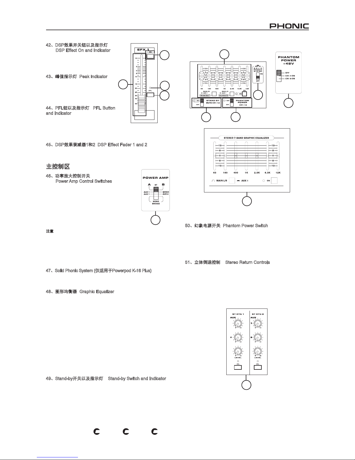
31
POWERPOD 1860 / K-12 / K-16
PL
US
PL
US
PL
US
42、DSP效果开关钮以及指示灯
DSP Effect On and Indicator
按下 此按 钮,可 开启或关闭 对应的
效果 面板 。效果 处理器开启 时,对
应的LED指示灯将变亮。
43、峰值指示灯 Peak Indicator
当数字效果处理器超负荷时 ,L ED
峰值 指示 灯将变 亮。建议调 节输入
声道的EFX 1和2使的峰值指示灯不
会闪亮。
44、PFL钮以及指示灯 PFL Button
and Indicator
PFL(Pre-Fader-Listen)推杆前监听
按钮可 监听对应声道输至控制室/耳
机CTRL RM/PH ONES控制(推杆前,推杆后)的信号,使用耳机
监听或舞台监听。PFL开启时相应的绿色LED指示灯将闪亮。
45、DSP效果衰减器1和2 DSP Effect Fader 1 and 2
此控制可调节对应数字效果处理器输往主混音总线的信号的音
量。
主控制区
46、功率放大控制开关
Power Amp Control Switches
此开关可控制功率放大器的活性和强度。使用
左边的开关可在不同信号间选择,决定哪些信
号将经 内 建 功率放大 器 处 理 并输往主 音 箱 输
出。此开关可选择的范围为:立体声信号,最
终音量经Main L/R推杆调节;AUX 1/M ono,
最终音量经AUX推杆和M o n o推杆调节;AU X
1/AUX 2输出,最终音量经A U X 1和2推杆调
节;Mono桥接,最终音量经Mono推杆调节。
注意:采用Mono桥接式连接时,请勿将音箱接至1/4”耳机插孔或后面板上
的专业音箱插孔B音箱连接器。
右 边 的 开 关 可 对 功 率 放 大 进 行 调 节 , 范 围 为 1 0 0 W / 声 道
~300W/500W/声道(仅适用于Powerpod K-12 Plus 和Powerpod
K-16 Plus)。调节取决于场地的大小以及您所使用的音箱的性能。
Powerpod 1860 Plus无此功能。
47、Solid Phonic System (仅适用于Powerpod K-16 Plus)
使用此开关(只有Powerpod K-16 Plus才有)可对整个音频,无论
是高频还是是低频,进行少量的增强或削减。
48、图形均衡器 Graphic Equalizer
这个立 体7段图形均衡 器可对信号的频 率响应进行 1 2 d B的增强
或衰减调节。AUX 1/L/R钮可在AUX 1总线和Main L/R总线信号
切换均衡器的作用。选择L/R时,均衡器将不仅作用于两个主立
体声信号,还可调节单通道Mo no信号。按下O n钮,可开启均衡
器,相应的LED指示灯也将变亮。
Powerpod K-12 Plus和Powerpod K-16 Plus还设有另一功能,回授
检测系统。当某一特定频率段发生信号回授时,位于均衡器滑行
VR控制上的独立LED指示灯
将变亮。降低该频率段的音量即可消除其信号回授;回授消除后
LED灯也会关闭。按下FB D钮,可对AUX 1的最终信号进行回授
检测。释放按钮,可对Main L/R的信号进行回授检测。建议使用
者将AUX 1/ L/R的设置设成与FBD钮一样,以证实简单的调节频
率即可产生回授现象。
49、Stand-by开关以及指示灯 Stand-by Switch and Indicator
Powerpod K-12 Plus的此开关可对声道1至15/16进行静音控制,
Powerpod K-16 Plus的可对声道1至11/12进行削减。此功能在
现场表演中很实用,开启时Tape In和立体AUX Return并没有静
音,在表演间隔中可播放CD播放器或其它输入设备的音频,使
得麦克风不至于产生信号回授。按下Stand-by按钮,LED指示灯
将变亮。
50、幻象电源开关 Phantom Power Switch
打开此按钮即可开启Powerpod K-12 Plus声道1至8的幻象电源,
Powerpod K-16 Plus的为声道1至12,可接入电容式麦克风。幻
象电源开启时,对应的LED指示灯将变亮。Powerpod 1860 Plus
的此开关有3个档位,可开启声道1至7或声道1至4,或不启动任
何声道的幻象电源。
51、立体倒送控制 Stereo Return Controls
这些控制可调节立体倒送输入插孔接收的信号的音量。若由两个
辅助音量控制组成,即可调节输往辅助混音总线的信号的音量;
若为单个音量控制,即调节的为输往主混音总线的信号的音量。
对应的P F L按钮可 将立体倒送信号 直接输往控制室 /耳机C T R L
RM/PHONES控制,不受音量控制的影响。开启PFL按钮将伴随
LED指示灯的闪亮。
42
43
45
44
46
48
Powerpod 1860 Plus
48
49
50
47
50
Powerpod
1860 Plus
51
Page 32
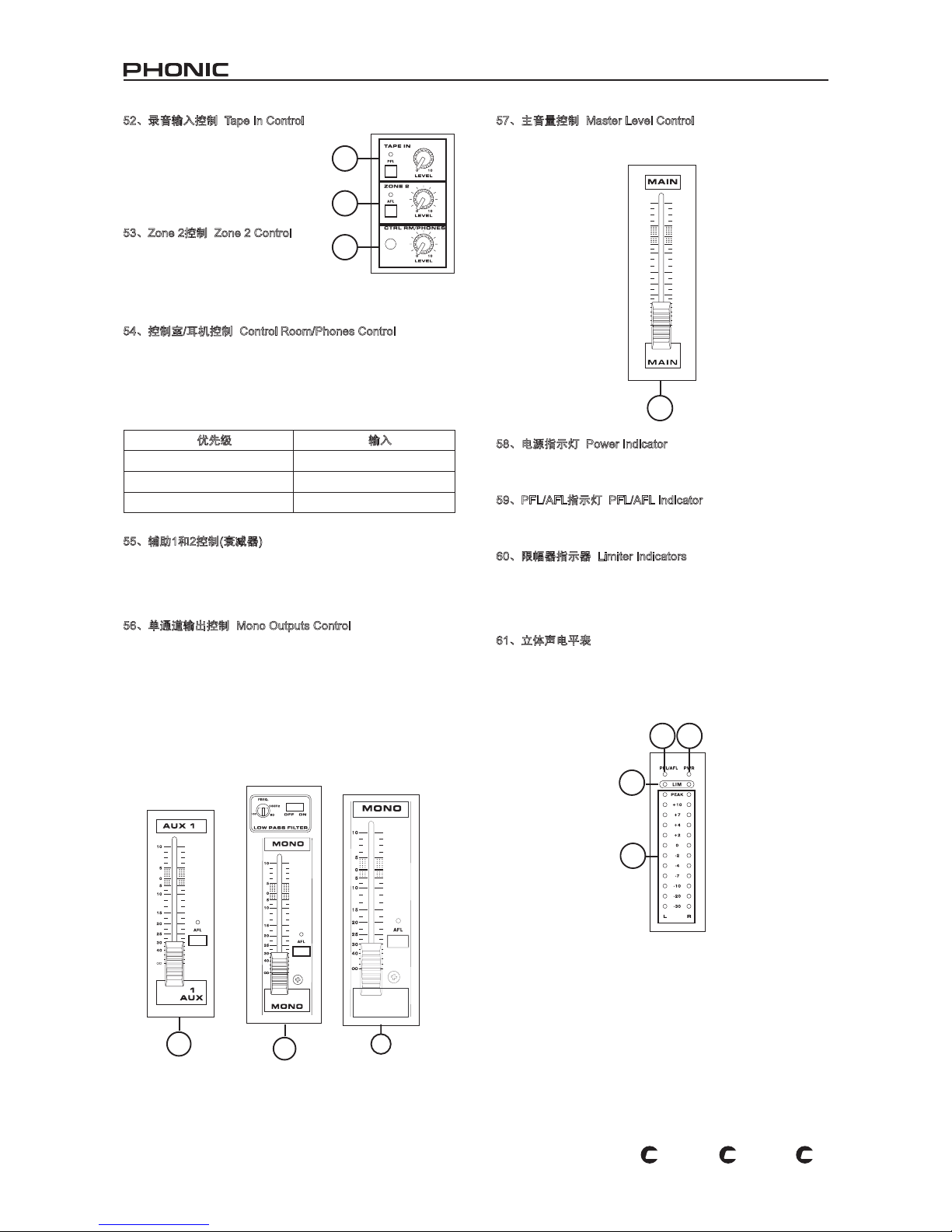
32
POWERPOD 1860 / K-12 / K-16
PL
US
PL
US
PL
US
55
56
56
Powerpod 1860 Plus
57
60
61
59 58
52、录音输入控制 Tape In Control
此控制 可调节输往 主混音的录 音输入
的音量 。对应的P FL钮可将录 音输入
的信号输送至控制室/耳机CTR L RM/
PH O NE S。此种情 形下, 录音输 入
Tape In将不影响输往PFL/AL总线的信
号。
53、Zone 2控制 Zone 2 Control
此控制可调节Zone 2输入输往Zone 2
输出的 信号的音量。对应的A F L钮可
将Zone 2音频输入输送至控制室/耳机
CTRL RM/PH ONES。开启AFL将伴
随LED指示灯的闪亮。
54、控制室/耳机控制 Control Room/Phones Control
Po werp od系列顶面板上的此旋钮可调节输往控制室/耳机CTR L
RM/ P H O NES输出的信号的音量。任何开启的P F L声道的信号
将优先于其它,并能与另一个P FL信号同时传送。若未开启任何
PF L按钮,将传送开启的AF L声道的信号。未开启PF L或AF L开
关,将输送Main L/R混音。
优先级 输入
高
PFL
中
AFL
低
Main L/R
55、辅助1和2控制(衰减器)
此控制可调节输往AUX输出的信号的音量,可连接地面监听器,
以及外部信号处理器。对应的AFL钮可将对应衰减器(推子后)处
理过的辅助混音总线的信号输往控制室/耳机CTRL RM/PHONES
控制。开启AFL将伴随LED指示灯的闪亮。
56、单通道输出控制 Mono Outputs Control
单通道Mono的推杆可调节输往单通道Mono输出插孔的最终信号
的音量。对应的A FL钮可将推杆后信号输送至控制室/耳机CT RL
RM/PHONES控制。
对应的低通滤波控制(仅适用于Powerpod K-12 Plus和Powerpod
K-16 Plu s)可对单通道Mono输出的高频噪音进行1 8dB/o ct的削
减,提供共为清晰的低音音效。此开关可开启或关闭低通滤波
器,相应的控制可在60~160Hz间对信号进行削减。
57、主音量控制 Master Level Control
这个推杆可调节输往内建功率放大器和各个输出的Main L/R的信
号的音量。
58、电源指示灯 Power Indicator
开启Powerpod系列后,位于PFL/AFL指示器旁边的电源指示灯
将变亮。
59、PFL/AFL指示灯 PFL/AFL Indicator
这个测量表上方的PF L/A FL指示灯为双色的,开启PF L开关时为
绿色,开启AFL时显示为红色。
60、限幅器指示器 Limiter Indicators
Po werpo d系列的内建立体功率放大器内设有两个限幅器。开启
限幅器后,当功率放大器的信号音量过高,L ED灯将闪亮指示电
路可能超载。若指示灯频繁闪亮,请将功率放大器声源的对应输
入的音量控制关小。
61、立体声电平表
这个电平表可视觉化的显示立体Main L/R输出电平。各声道的12
段电平表含绿色,黄色,红色三色LED指示灯,以及一个峰值指
示灯,可显示-30dBu ~ +10dBu的电平。若开启PFL或AFL,主
电平表将高可视化的显示PFL或AFL信号的电平。
52
53
54
Page 33
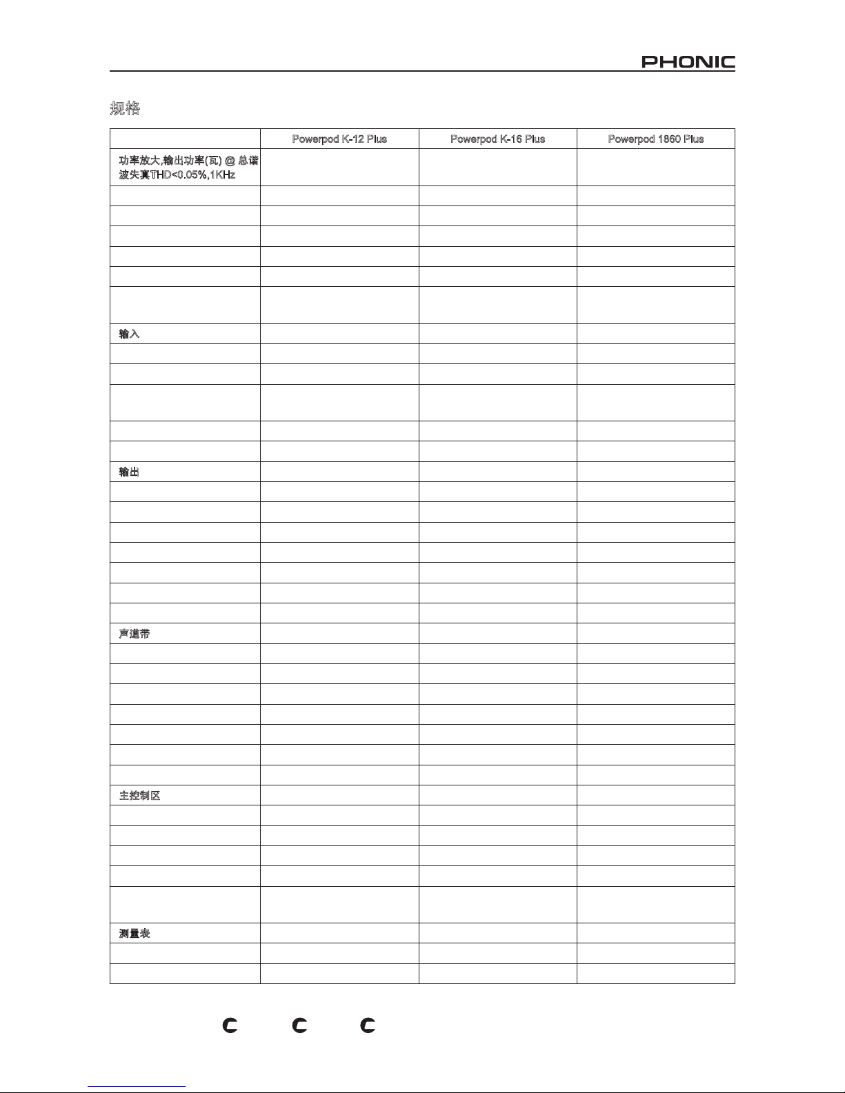
33
POWERPOD 1860 / K-12 / K-16
PL
US
PL
US
PL
US
规格
Powerpod K-12 Plus Powerpod K-16 Plus Powerpod 1860 Plus
功率放大,输出功率(瓦) @ 总谐
波失真THD<0.05%,1KHz
功率通道数
2 2 2
限幅器
2 2 2
8欧姆/声道 330 330 260
4欧姆/声道 500 500 400
8欧姆桥接单通道Mono 1000 1000 800
功率放大选择开关
500W+500W,300W+300W,
100W+100W
500W+500W,300W+300W,
100W+100W
N/A
输入
总声道数
10 14 10
平衡单通道麦克风/高电平声道
8(XLR + 1/4” Combo插孔) 12(XLR + 1/4” Combo插孔) 8(XLR + 1/4” Combo插孔)
立体高电平通道带麦克风前置
放大
2(XLR& 2 x 1/4”) 2(XLR& 2 x 1/4”) 2(XLR& 2 x 1/4”)
立体辅助倒送
2 2 2
2T输入 1(1 x 迷你立体 & 2 x RCA插孔) 1(1 x 迷你立体 & 2 x RCA插孔) 1(1 x 迷你立体 & 2 x RCA插孔)
输出
主 L/R 立体输出
2 x 1/4”TS,非平衡 2 x 1/4”TRS,非平衡 2 x 1/4”TS,非平衡
主单通道
1/4” TS,非平衡 1/4” TRS,非平衡 1/4” TS,非平衡
辅助输出&效果输出
4 x 1/4”TS,非平衡 4 x 1/4”TRS,非平衡 4 x 1/4”TS,非平衡
耳机
1 1 1
控制室或Zone 2输出
2 x 1/4”TS,非平衡 1/4” TRS,非平衡 1/4” TS,非平衡
录音输出
1 x 迷你立体,2 x RCA插孔 1 x 迷你立体,2 x RCA插孔 1 x 迷你立体,2 x RCA插孔
音箱输出
1x Speakon & 2 x 1/4”TS/声道 1x Speakon & 2 x 1/4”TRS/声道 1x Speakon & 4 x 1/4”TS/声道
声道带
10 14 10
辅助控制
4 4 4
音场/平衡控制 是 是 是
声道开关/削减 是 是 是
声道Solo/PFL带测试 是 是 是
LED指示器
开启,峰值,信号,PFL 开启,峰值,信号,PFL 开启,峰值,信号,PFL
音量控制
60mm 推杆 60mm 推杆 60mm 推杆
插入点 是 是 是
主控制区
辅助输出控制
2,60mm 推杆 2,60mm 推杆 2,60mm 推杆
效果倒送至监听器
4 4 3
耳机/控制室/Zone 2音量控制 是 是 是
控制室模式
ST,PFL/AFL ST,PFL/AFL ST,PFL/AFL
衰减器
2 x EFX,AUX 1,AUX 2,Mono,Main
L/R (60mm 推杆)
2 x EFX,AUX 2,Mono,Main L/R
(60mm 推杆)
EFX,AUX 2,Mono,Main L/R
(60mm 推杆)
测量表
声道数
2 2 2
段数
13 13 13
Page 34
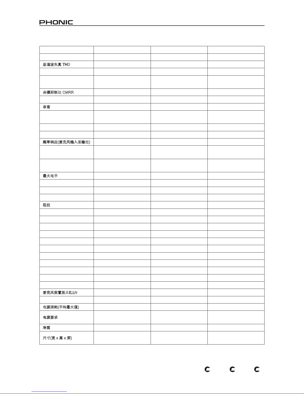
34
POWERPOD 1860 / K-12 / K-16
PL
US
PL
US
PL
US
幻象电源供应
+48V DC +48V DC +48V DC
开关 主控制 +10 主控制 +14 主控制 +10
总谐波失真 THD
功率输出 1KHz,20Hz~20KHz
@250W,4ohms<0.5% @250W,4ohms<0.5% @200W,4ohms<0.5%
任何输出,1K Hz @ +14 dBu,
20Hz~20KHz,声道输入
<0.3% <0.3% <0.3%
共模抑制比 CMRR
1KHz@-60dBu,增益最大 80 dB 80 dB 80 dB
串音
1KHZ @ 0 dBu, 频宽20Hz ~
20KHz,声道输入至Main L/R输出
声道衰减,其余一致
< -63dB < -63dB < -63dB
声道静音,其余一致
< -64dB < -64dB < -64dB
频率响应(麦克风输入至输出)
20Hz~20KHz,高电平
o/p@+4dBu至600欧姆
+0/-2dB +0/-2dB +0/-2dB
20Hz~20KHz,功率放大o/p1瓦
至8欧姆
+0/-2dB +0/-2dB +0/-2dB
最大电平
麦克风前置放大输入
+10dBu +10dBu +10dBu
其它输入
+22dBu +22dBu +22dBu
平衡输出
+22dBu +22dBu +22dBu
阻抗
麦克风输入
5K ohms 5K ohms 5K ohms
高电平输入
50K ohms 50K ohms 50K ohms
其它输入(除插入点外)
10K ohms 10K ohms 10K ohms
RCA 2T 输出 600 ohms 600 ohms 600 ohms
其它输出
150 ohms 150 ohms 150 ohms
均衡
3段,±15dB 3段,±15dB 3段,±15dB
低频均衡
80Hz 80Hz 80Hz
中频均衡
100-8K Hz,可扫频 100-8K Hz,可扫频 2.5KHz
第二中频均衡(ST 声道)
2.5KHz 2.5KHz 2.5KHz
高频均衡
12KHz 12KHz 12KHz
低切滤波器
75Hz(-18dB/oct) 75Hz(-18dB/oct) 75Hz(-18dB/oct)
麦克风前置放大E.I.N
150欧姆终止,最大增益 < -122 dBm < -122 dBm < -122 dBm
电源消耗(平均最大值)
500瓦 500瓦 400瓦
电源要求
100~120VAC,220~240VAC,50/
60Hz,视地区而定
100~120VAC,220~240VAC,50/
60Hz,视地区而定
可在115VAC&230VAC间切换
,50/60Hz
净重
14.5Kg(31.9 lbs) 19.5Kg(43.0 lbs) 14.3Kg(31.5lbs)
尺寸(宽 x 高 x 深)
483 x 142.6 x 466.2 mm
(19” x 5.6 “ x 18.4”)
583.2 x 142.6 x 466.2 mm
(23” x 5.6 “ x 18.3”)
448 x 147 x 465 mm
(17.6” x 5.8 “ x 18.3”)
Page 35
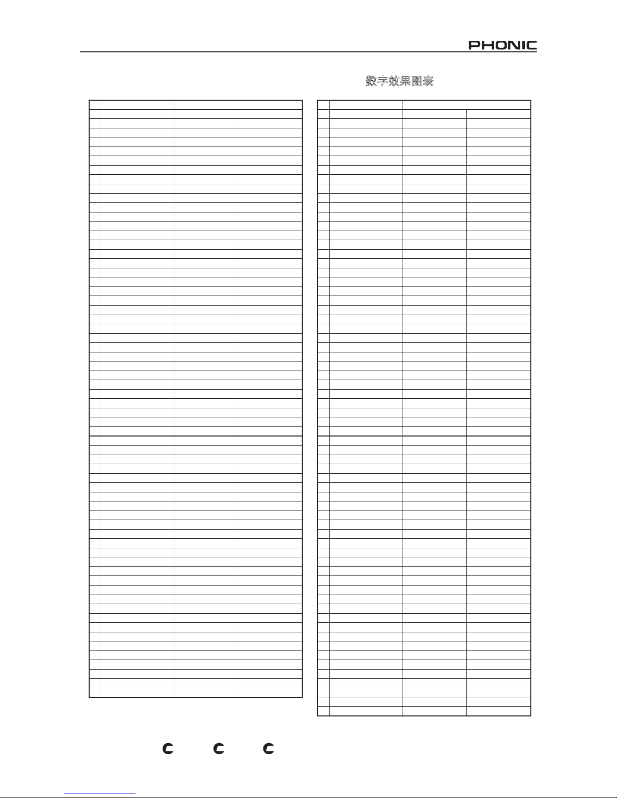
35
POWERPOD 1860 / K-12 / K-16
PL
US
PL
US
PL
US
数字效果图表
Tabla de Efectos Digitales
NO PROGRAM NAME PARAMETER SETTING
ROOM REV-TIME EARLY LEVEL
00 COMPACT ROOM 1 0.05 100
01 COMPACT ROOM 2 0.4 0
02 SMALL ROOM 1 0.45 100
03 SMALL ROOM 2 0.6 90
04 MID ROOM 1 0.9 100
05 MID ROOM 2 1 50
06 BIG ROOM 1 1.2 100
07 TUNNEL 3.85 100
HALL REV-TIME EARLY LEVEL
08 JAZZ CLUB 0.9 90
09 SMALL HALL 1 1.5 72
10 SMALL HALL 2 1.75 85
11 SPRING HALL 1.9 98
12 MID HALL 1 2.3 100
13 MID HALL 2 2.45 80
14 RECITAL HALL 2.7 96
15 BIG HALL 2 3.3 88
PLATE REV-TIME HPF
16 SMALL PLATE 0.9 0
17 TAIL PLATE 1.2 20
18 MID PLATE 1 1.3 0
19 MID PLATE 2 2.2 0
20 REVERSE PLATE 2.25 42
21 LONG PLATE 1 2.6 80
22 LONG PLATE 2 3 625
23 LONG PLATE 3 4.2 0
DELAY-1(stereo) DELAY AVERG. R-LEVEL
24 SHORT DELAY 1 0.07 60
25 SHORT DELAY 2 0.14 60
26 PING PONG DELAY 0.11 55
27 MID DELAY 1 0.15 55
28 MID DELAY 1 0.3 60
29 SHORT DELAY 1 (MONO) 0.06 100
30 MID DELAY 1 (MONO) 0.13 100
31 LONG DELAY 1 (MONO) 0.18 100
CHORUS LFO DEPTH
32 SOFT CHORUS 0.2 56
33 SOFT CHORUS 2 0.5 70
34 SOFT CHORUS 3 0.8 75
35 WARM CHORUS 1.8 85
36 WARMER CHORUS 1 3.2 80
37 WARMER CHORUS 2 5.2 45
38 WARMER CHORUS 3 7.8 52
39 HEAVY CHORUS 9.6 48
FLANGER LFO DEPTH
40 CLASSIC FLANGER 1 0.1 44
41 CLASSIC FLANGER 2 0.3 63
42 GENTLE FLANGER 0.6 45
43 WARM FLANGER 1.6 60
44 MODERN FALANGER 1 2 85
45 MODERN FALANGER 2 2.8 80
46 DEEP FALANGER 1 4.6 75
47 DEEP FALANGER 2 10 60
PHASER LFO DELAY
48 CLASSIC PHASER 1 0.1 3.6
49 CLASSIC PHASER 2 0.4 2.6
50 COOL PHASER 1.4 0.7
51 WARM PHASER 3.2 0.3
52 HEAVY PHASER 1 5 1.2
53 HEAVY PHASER 2 6 2.8
54 WILD PHASER 1 7.4 0.8
55 WILD PHASER 2 9.6 4.8
NO PROGRAM NAME PARAMETER SETTING
PAN SPEED TYPE
56 SLOW PAN 0.1 R-->L
57 SLOW PAN 1 0.1 R<-->L
58 SLOW PAN 2 0.4 R-->L
59 MID SHIFT 0.8 R<-->L
60 MID SHIFT 1 1.2 L-->R
61 MID SHIFT 2 1.8 L-->R
62 MID SHIFT 3 1.8 R-->L
63 FAST MOVE 3.4 R<-->L
TREMOLO SPEED MODE-TYPE
64 LAZY TREMOLO 0.8 TRG
65 VINTAGE TREMOLO 1.5 TRG
66 WARM TREMOLO 2.8 TRG
67 WARM TREMOLO 1 4.6 TRG
68 HOT TREMOLO 6.8 TRG
69 HOT TREMOLO 1 9.6 TRG
70 CRAZY TREMOLO 1 15 TRG
71 CRAZY TREMOLO 2 20 TRG
DELAY+REV REV DELAY-1
72 DELAY+REV 1 1 1
73 DELAY+REV 2 2 2
74 DELAY+REV 3 3 3
75 DELAY+REV 4 4 4
76 DELAY+REV 5 5 5
77 DELAY+REV 6 6 6
78 DELAY+REV 7 7 7
79 DELAY+REV 8 8 8
CHORUS+REV REV CHORUS
80 CHORUS+REV 1 1 1
81 CHORUS+REV 2 2 2
82 CHORUS+REV 3 3 3
83 CHORUS+REV 4 4 4
84 CHORUS+REV 5 5 5
85 CHORUS+REV 6 6 6
86 CHORUS+REV 7 7 7
87 CHORUS+REV 8 8 8
FLANGER+REV REV FLANGER
88 FLANGER+REV 1 1 1
89 FLANGER+REV 2 2 2
90 FLANGER+REV 3 3 3
91 FLANGER+REV 4 4 4
92 FLANGER+REV 5 5 5
93 FLANGER+REV 6 6 6
94 FLANGER+REV 7 7 7
95 FLANGER+REV 8 8 8
GATED-REV RELEASE REV
96 GATED-REV-1 9 0.02 TAIL PLATE
97 GATED-REV-2 10 0.2 TAIL PLATE
98 GATED-REV-1 9 0.02 REVERSE PLATE
99 GATED-REV-2 10 0.5 REVERSE PLATE
TAP DELAY FB LEVEL RANGE
A0 TAP DELAY 0 100mS - 2.7S
A1 TAP DELAY 10 100mS - 2.7S
A2 TAP DELAY 20 100mS - 2.7S
A3 TAP DELAY 30 100mS - 2.7S
A4 TAP DELAY 40 100mS - 2.7S
A5 TAP DELAY 50 100mS - 2.7S
A6 TAP DELAY 60 100mS - 2.7S
A7 TAP DELAY 70 100mS - 2.7S
A8 TAP DELAY 80 100mS - 2.7S
TEST TONE FREQUENCY SHAPE
T0 LOW FREQUENCY 100Hz SINEWAVE
T1 MID FREQUENCY 1kHz SINEWAVE
T2 HIGH FREQUENCY 10kHz SINEWAVE
PN PINK NOISE 20Hz~20kHz
Digital Effect Table
Page 36
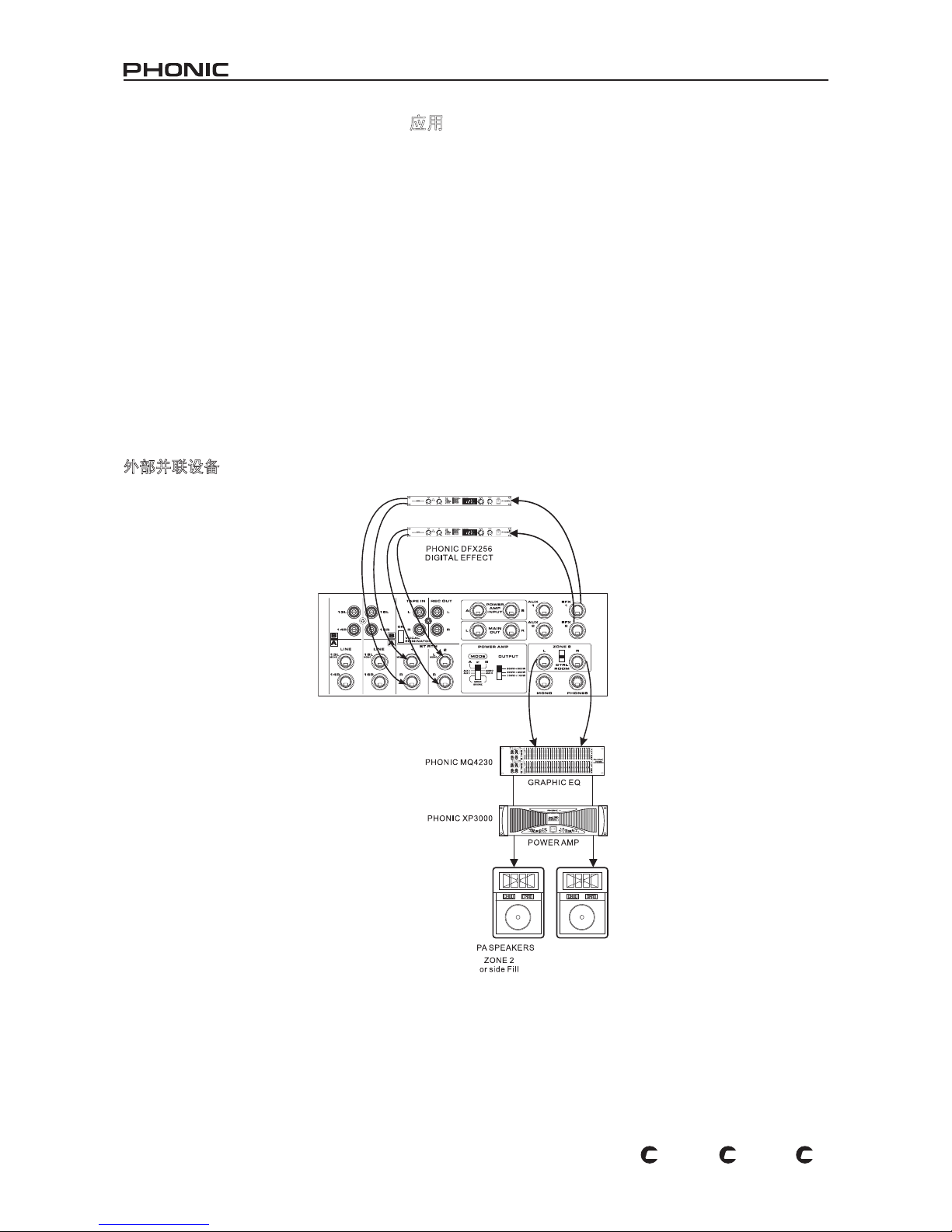
36
POWERPOD 1860 / K-12 / K-16
PL
US
PL
US
PL
US
APPLICATION APLICACIÓN 应用
There are potentially hundreds of ways to connect instruments and devices to the K-12 Plus, K-16 Plus and 1860 Plus Powered Mixers.
It is advisable that you explore the functions and nd the best setup possible for your needs, which may depend on what instruments
you wish to connect, as well as how many external devices you wish to connect and your required monitoring applications. Combining
the use of different instruments with the mixer's special functions (such as digital effect processing) will ensure that your audio sounds
exactly the way you want it.
Existen miles de maneras potenciales de conectar instrumentos y dispositivos a las Mezcladoras Amplicadas K-12 Plus, K-16 Plus y
1860 Plus. Se recomienda que explore las funciones y encuentre la mejor conguración posible para sus necesidades, que pudieran
depender de qué instrumentos quisiera conectar, así como cuántos dispositovos externos se quiere conectar y sus aplicaciones de
monitoreo requeridas. Combinar el uso de de diferentes instrumentos con las funciones especiales de la mezcladora (como el procesamiento de efecto digital) asegurará que su audio se escucha exactamente como usted quiere.
接下来的几页将向您介绍Powerpod系列的应用范例。所举的实例并不能涵盖Powerpod系列的全部功能,却可为您安装设备带来一定的参
考价值。正确的连接麦克风,吉它,电子琴,以及信号处理器,音箱,将为您在现场演出以及不同场合的表演带来意想不到的效果。
Adding External Parallel Devices
Agregando Dispositivos Externos Paralelos
外部并联设备
数字效果处理器
图形均衡器
功率放大器
PA 音箱
ZONE 2
或边缘插入
EFECTO DIGITAL
EQ GRÁFICO
AMP DE POTENCIA
ZONA 2
Relleno lateral
PA ALTAVOCES
Page 37
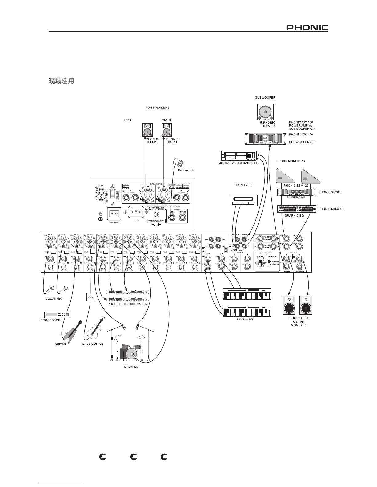
37
POWERPOD 1860 / K-12 / K-16
PL
US
PL
US
PL
US
Live Application
Aplicación en Vivo
现场应用
RECORDER
FOH 音箱!
左
超低音单元
Phonic XP3100
功率放大器 W/
超低音单元 O/P
MD , DAT , 唱片播放器
右
脚踏开关
地面监听音箱
CD 播放器
功率放大器
图形均衡器
麦克风
有源监听音箱
信号处理器
Phonic PCL 3200 压缩器/限幅器
电子琴
吉它
低音吉它
架子鼓
ALTAVOCES FOH
IZQUIERDO
DERECHO
INTERRUPTOR DE PEDAL
AMPLIFICADOR DE POTENCIA CON
MONITORES DE PISO
ENERGÍA AMP
EQ GRAFICO
TECLADO
MONITOR ACTIVO
PROCESADOR
GUITARRA
GUITARRA DE BAJO
BATERIA
REPRODUCTOR DE CD
GRABADORA DE MD, DAT,
AUDIO CASSETTE
Page 38
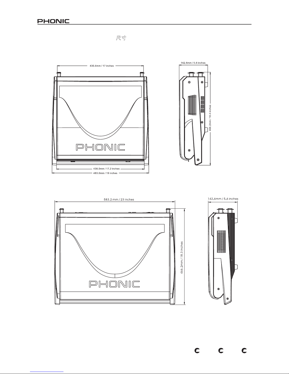
38
POWERPOD 1860 / K-12 / K-16
PL
US
PL
US
PL
US
measurements are shown in mm/inches
DIMENSIONS DIMENSIONES 尺寸
Todas las medidas están mostradas en mm/pulgadas.
尺寸是以毫米
mm/英寸inch
表示。
Powerpod K-12 Plus and Powerpod 1860 Plus
Powerpod K-16 Plus
Page 39
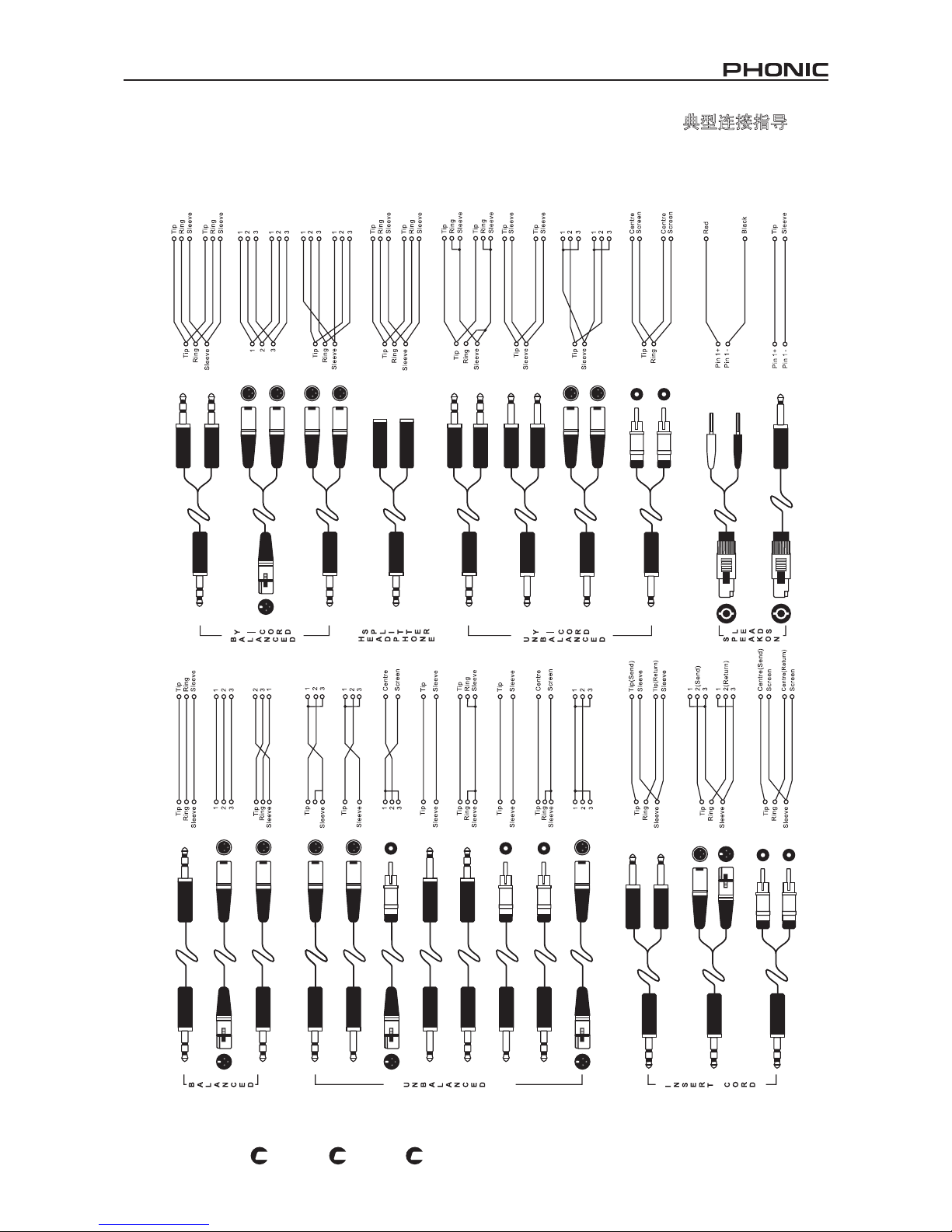
39
POWERPOD 1860 / K-12 / K-16
PL
US
PL
US
PL
US
典型连接指导
Guías de Conexiones ComunesTypical Connecting Leads
Page 40
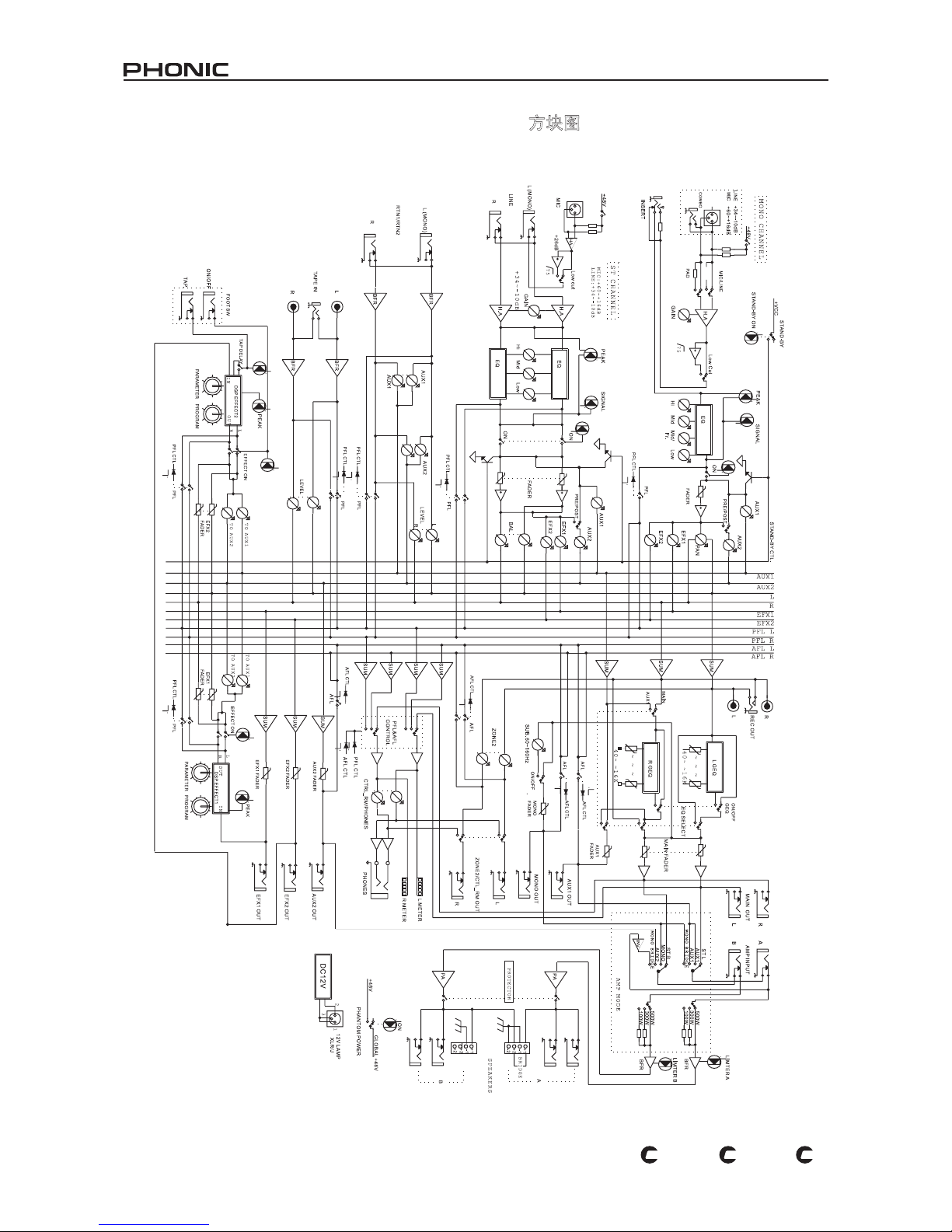
40
POWERPOD 1860 / K-12 / K-16
PL
US
PL
US
PL
US
BLOCK DIAGRAM DIAGRAMA DE BLOQUE 方块图
Powerpod K-12 Plus
Page 41
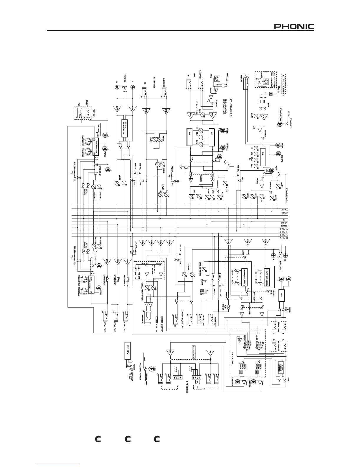
41
POWERPOD 1860 / K-12 / K-16
PL
US
PL
US
PL
US
Powerpod K-16 Plus
Page 42
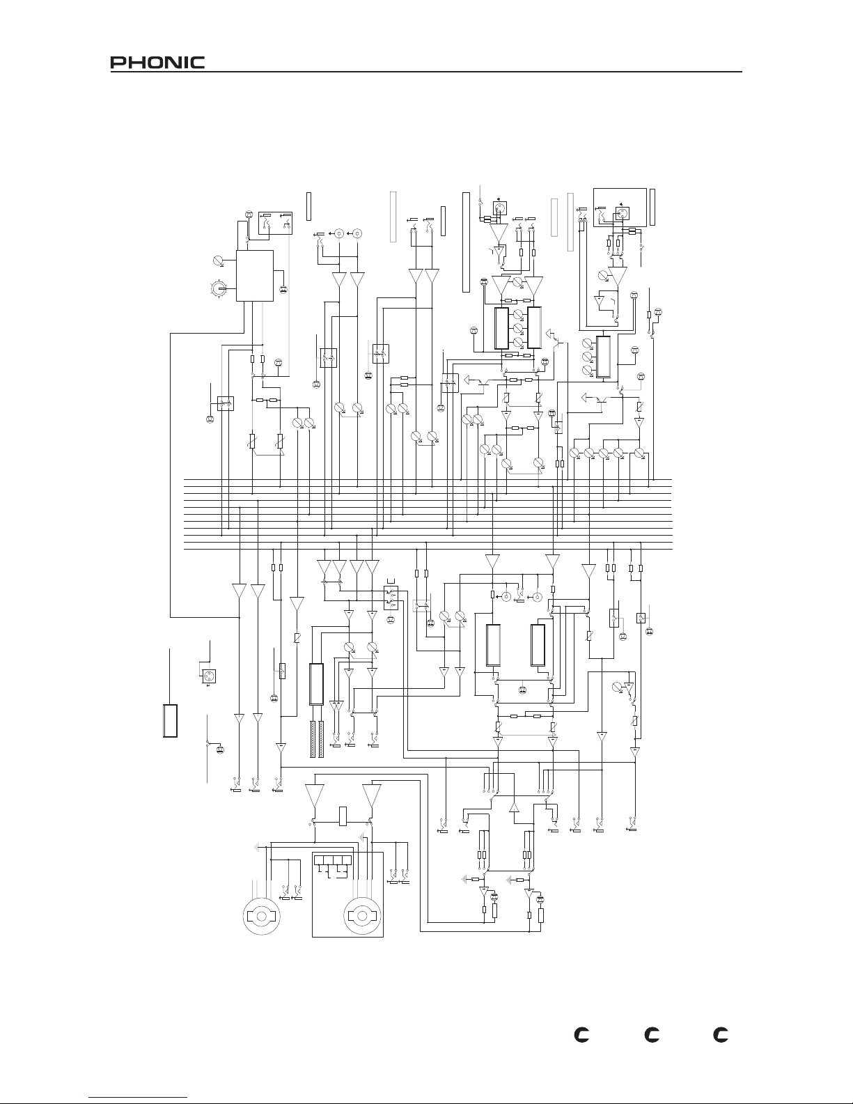
42
POWERPOD 1860 / K-12 / K-16
PL
US
PL
US
PL
US
Powerpod 1860 Plus
T
U
PNI
E
P
AT
z
H
57
A
_
E
U
C
E
NN
AH
C
O
N
O
M
L
N
T
R T
S
1
_
E
U
C
P
A
_
E
U
C
L
ENN
A
H
C
EH
T OT 1 L
ENN
AH
C 8
N
TR
TS S
A
E
MA
S
2 N
TR T
S 1
_E
U
C P
/2 E
N
O
Z
A
_E
UC
L
R
W
S T
O
OF
P_E
U
C
1XU
A
ON
OM
G
D
I
R
B
E
2
X
U
A
0
03 W
W
0
02W00
1
0
0
3
W
W002W
0
0
1
P_EU
C
MO
OR
L
OR
TNOC
XU
A
/
NI
A
M 1
OB
MO
C
B
d01-~
43
+
:
E
NI
L
d
6
1
+~
06
+
:CIM
B
A
H
FB R
F
B
R
F
B
R
F
B
R
US
M
US M
U
S M
U
S M
US M
US
M
zH
K61
-
-
-
-
- -
-
04
HK
6
1
-
-
-
-
-
-
-
0
4
z
F
A L
F
P
L
F
P L
F
P
L
R
L
F
A L
AH
E
NOT
D
N
AB
3
A
H
EN
OT
D
N
AB
3
E
NNA
H
C
O
ERE
T
S
L
R21/
)O
NO
M
(
1
1
L
EN
N
AHC
E
HT
OT
R01
/
)O
NO
M
(L9 L
ENNA
H
C
A
H
zH57
B
d61
+~
06+:
CI
M
P
_E
U
C
B
d
01
-~4
3+:
ENI
L
US
M
US
M
-2
B:
-2
/
+
2
+1
+
2
AP
A
P
A
E
G
D
IR
B
G
DIRB
:
+2/
+
1
E
-1
A:
-1
/+1
B
P
_E
U
C
Y
L
P
PU
S
R
EW
O
P M
O
T
N
AH
P
US M
US M
A
_
E
U
C
CUE_P
A
_E
U
C
F
P
L
V84
+
EFX 2
C
D
V
2
1
H
0
6
/
0
5
C
A
V0
6
2~
0
9 z
DV
+ D
Y
B
-
D
NA
T
S
STAND-BY
V84+
LEFT
AUX 1
LEFT
RIGHT
AUX 2
AUX 1
EFX 2
PFL L
V8
4
+
V84
+
L
A
B
O
L
G
UO
R
T
C
EF
FE
T
T
U
O L T
C
E
F
F
E
AUX 2
N
I
T
C
E
F
FE
AFL LAFL L
AFL RAFL R
PFL L
PFL R
EFX 1
PFL R
RIGHT
EFX 1
N
O
Q
E
XUA 1
E
DAF
R
NI
A
M
L
E
TE
M
AR
A
P R
E
N
O
T
DNAB
3
XUA 1
OK
A
EP
S
E
G
D
IR
B
B/
A
N
+1
-1
+2
-
2
I
M
C
NO
R
01
OR
T
NOC L
M
O
O
R LR
T
C
/
YB-
DN
A
T
S
21-
1
H
C
E
T
U
M
X
U
A
2
E
N
O
Z 2
N
O
O
ER
E
T
S I
N
I
M
O
N
O
M
T
S
B
N
O
RN
I
_
P
M
A_
P
X
F
E
2
ED
A
F
R
I
N
ON
1
A
E
P
K
IS G
TC
E
F
F
E
E
V
I
R
D
D
EL
H
GIH
H
GI
H
R
_ C
E
R
O
L W
NI
A
M R
ED
A
F
R
E
NIL
X
F
E
2
XU
A 2
ON
O
M
(
L
)
Q
E
G
DNAB
01
R
R
E
TIM
I
L
A
IM
I
L T
S
ENO
H
P
F
P
L
X
UA
2
F
A/
L
FP L
1
XUA
TS A
L
E
LL
A
RA
P_
A
NA
P
PL
F
EVEL L
P
A
T
I
M
D
IM
D
N
AP
PM
AL
V2
1
XU
A
2
UC W
OL T
FA L
M
AR
GO
R
P
EDAF R
ON
O
M
XU
A 1
O
NOM
ED
A
F
R
IA
G
N
ENOZ 2
U
C
WOL
T
R
X
FE 1
N
OK
A
E
PS
B
+1-1+
2
-
2
OL
W
O
L W
H
061
-
-
- 06 z
P
A
T
XU
A 1
C
E
T
O
RP T
A
L
E
D
P
AT
Y
E
D
A
F R
I
N
OM 2
XU
A
2
2
XF
E
NO
I
M
C
A
E
P
K
IMD
L
A
E
P K
NI
A
M
N
O
F
O/
N
O
F
L
ELL
AR
A
P_
B
L
_
C
ER
ENI
L
/
C
I
M
F
O
/
N
O
P
S
D
F
XU
A
1
L
1X
F
E
G
B
/LN
I_
P
M
A_
P
ON
O
M(L
9
)
SD
P
SM
A
RG
O
R
P
61
S
ENO
H
P
E
VE
L L
IAG
N
Q
E
G DN
A
B 01
L
X
F
E
1
F
A
L
H
GIH
R
I
S
G
E
DA
F
R
R
R
E
T
I
M
I
L
B
I
M
I
L
T
R
E
S
NI
T
G
NI
H
CT
IW
S
YLP
P
US
R
EW
O
P
O
E
RE
T
S
INI
M
Page 43

[email protected] http://www.phonic.com
CÓMO COMPRAR EQUIPO ADICIONAL
Y ACCESORIOS DE PHONIC
Para comprar equipos y accesorios opcionales de
Phonic, póngase en contacto con cualquiera de los
distribuidores autorizados de Phonic. Para una lista
de los distribuidores de Phonic visite nuestra página
web en www.phonic.com y entre a la sección Get
Gear. También, puede ponerse en contacto directa
mente con Phonic y le ayudaremos a encontrar un
distribuidor cerca de usted.
SERVICIO Y REPARACIÓN
Para refacciones de reemplazo y reparaciones, por
favor póngase en contacto con nuestro distribuidor
de Phonic en su país. Phonic no distribuye manuales
de servicio directamente a los consumidores y, avisa
a los usuarios que no intenten hacer cualquier
reparación por si mismo, haciendo ésto invalidará
todas las garantías del equipo. Puede encontrar un
distribuidor cerca de usted en
http://www.phonic.com/where/.
INFORMACIÓN DE LA GARANTIA
Phonic respalda cada producto que hacemos con
una garantía sin enredo. La cobertura de garantía
podría ser ampliada dependiendo de su región.
Phonic Corporation garantiza este producto por un
mínimo de un año desde la fecha original de su
compra, contra defectos en materiales y mano de
obra bajo el uso que se instruya en el manual del
usuario. Phonic, a su propia opinión, reparará o
cambiará la unidad defectuosa que se encuentra
dentro de esta garantía. Por favor, guarde los recibos
de venta con la fecha de compra como evidencia de
la fecha de compra. Va a necesitar este comprobante
para cualquier servicio de garantía. No se aceptarán
reparaciones o devoluciones sin un número RMA
apropiado (return merchandise autorization). En
orden de tener esta garantía válida, el producto
deberá de haber sido manejado y utilizado como se
describe en las instrucciones que acompañan esta
garantía. Cualquier atentado hacia el producto o
cualquier intento de repararlo por usted mismo,
cancelará completamente esta garantía. Esta
garantía no cubre daños ocasionados por accidentes, mal uso, abuso o negligencia. Esta garantía es
válida solamente si el producto fue comprado nuevo
de un representante/distribuidor autorizado de
Phonic. Para la información completa acerca de la
política de garantía, por favor visite
http://www.phonic.com/warranty/.
SERVICIO AL CLIENTE Y SOPORTE
TÉCNICO
Le invitamos a que visite nuestro sistema de ayuda
en línea en www.phonic.com/support/. Ahí podrá
encontrar respuestas a las preguntas más frecuen
tes, consejos técnicos, descarga de drivers, instruc
ciones de devolución de equipos y más información
de mucho interés. Nosotros haremos todo el
esfuerzo para contestar sus preguntas lo antes
posible.
TO PURCHASE ADDITIONAL
PHONIC GEAR AND ACCESSORIES
To purchase Phonic gear and optional
accessories, contact any authorized
Phonic distributor. For a list of Phonic
distributors please visit our website at
www.phonic.com and click on Get Gear.
You may also contact Phonic directly and
we will assist you in locating a distributor
near you.
SERVICE AND REPAIR
For replacement parts, service and repairs
please contact the Phonic distributor in
your country. Phonic does not release
service manuals to consumers, and advice
users to not attempt any self repairs, as
doing so voids all warranties. You can
locate a dealer near you at
http://www.phonic.com/where/.
WARRANTY INFORMATION
Phonic stands behind every product we
make with a no-hassles warranty.
Warranty coverage may be extended,
depending on your region. Phonic Corpo
ration warrants this product for a minimum
of one year from the original date of
purchase against defects in material and
workmanship under use as instructed by
the user’s manual. Phonic, at its option,
shall repair or replace the defective unit
covered by this warranty. Please retain the
dated sales receipt as evidence of the date
of purchase. You will need it for any
warranty service. No returns or repairs will
be accepted without a proper RMA number
(return merchandise authorization). In
order to keep this warranty in effect, the
product must have been handled and used
as prescribed in the instructions accompa
nying this warranty. Any tempering of the
product or attempts of self repair voids all
warranty. This warranty does not cover
any damage due to accident, misuse,
abuse, or negligence. This warranty is
valid only if the product was purchased
new from an authorized Phonic
dealer/distributor. For complete warranty
policy information, please visit
http://www.phonic.com/warranty/.
CUSTOMER SERVICE AND
TECHNICAL SUPPORT
We encourage you to visit our online help
at http://www.phonic.com/support/. There
you can find answers to frequently asked
questions, tech tips, driver downloads,
returns instruction and other helpful
information. We make every effort to
answer your questions within one business
day.
购买Phonic产 品 及其周 边
器材
使用者如需购买Phonic产品及其周边
器材,请与Phonic授权的经销商取得
联 系 。 访 问 我 们 的 网 站
www.phonic.com,点击 Get Gear 即
可查询Phonic地 区 经 销商的联系方
式。您也可直接联系Phonic公司,我
们将协助您快速定位离您最近的经销
商。
服务与维修
订购替换零件或维修事宜,请与您所
在地区的Phonic经销商联系。Phonic
不对使用者发行维修手册,且建议使
用者切勿擅自维修机器,否则将无法
获 得 任 何 保 固 服 务 。 您 可 登 录
http://www.phonic.com/where/定位离
您最近的经销商。
产品保固资讯
Phonic承诺对每项产品提供最完善的
保固服务。我们将根据客户群体所在
的地区来拓展我们的服务所涵盖的范
围。自原始购买日起,Phonic即对在
严格遵照使用说明书的操作规范下,
因产品材质和做工所产生的问题提供
至少 1年的保 固服务。Phonic可 在此
保固范围内任意地选择维修或更换缺
陷产品。请务必妥善保管购买产品的
凭证,以 此 获 得 保 固 服 务 。 未 获 得
RMA号的将不受理退货,以及保固服
务。保固服务只限于正常使用情况下
产生的问题。使用者需严格遵照使用
说明书正确使用,任何肆意损坏或擅
自维修机器,意外事故,错误使用,
人为疏忽 , 都 将 不 在 保 固 受 理 范 围
内。此外,担保维修只限于在授权经
销商处的有效购买。欲知全部的保固
政 策 资 讯 , 请 参 考
http://www.phonic.com/warranty/。
客户服务和技术支持
欢 迎 您 访 问 我 们 的 网 站
http://www.phonic.com/support/。从
该网站上,您可获得各种常见问题的
答案,技 术 指 导 , 并 可 下 载 产 品 驱
动,获得有关退货指导以及其它帮助
资讯。我们竭尽全力在一个工作日内
回复您的询问。
Page 44
 Loading...