

Page 1
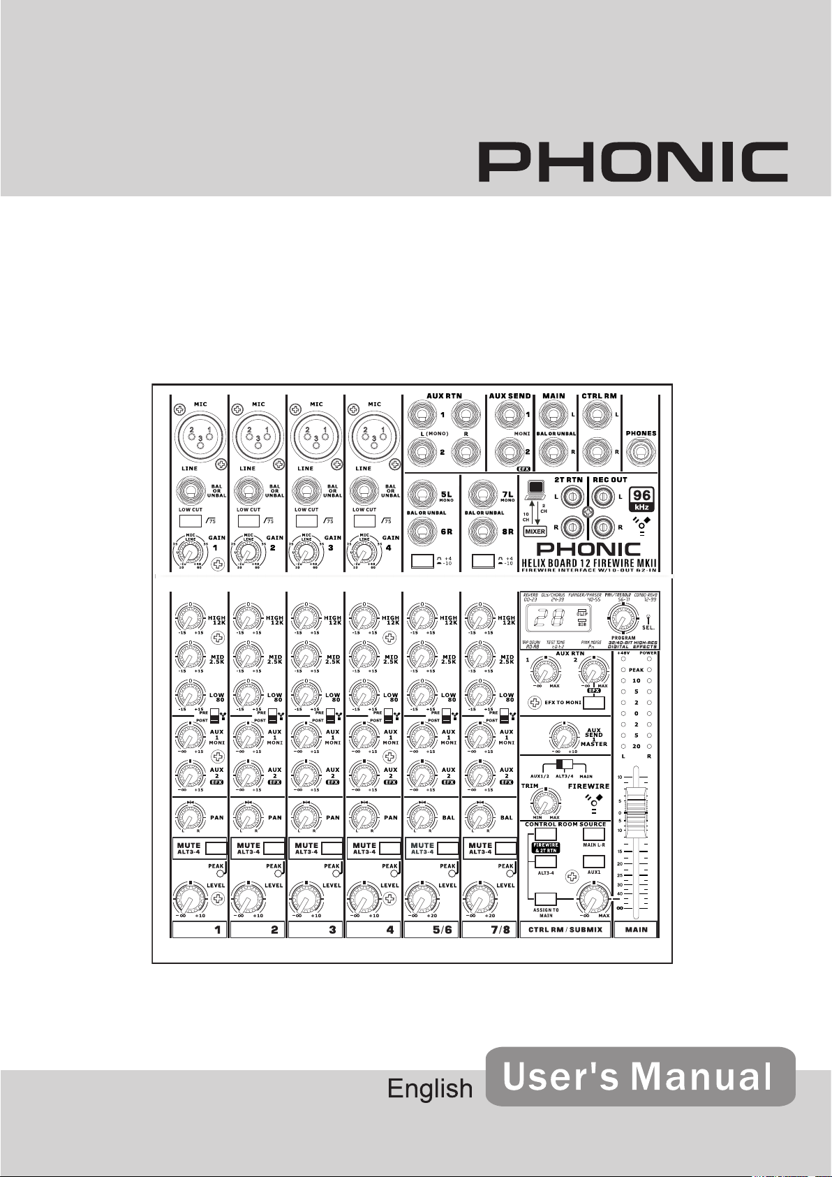
HELIX BOARD 12 FIREWIRE MKII
FireWire-enabled Mixing Console
Page 2
1. Re ad the se i ns tr uc ti on s be fo re o pe ra ti ng t hi s
apparatus.
2. Keep these instructions for future reference.
3. Heed all warnings to ensure safe operation.
4. Follow all instructions provided in this document.
5. Do not use this apparatus near water or in locations
where condensation may occur.
6. Clean only with dry cloth. Do not use aerosol or liquid
cleaners. Unplug this apparatus before cleaning.
7. Do not block any of the ventilation openings. Install
in accordance with the manufacturer’s instructions.
8. Do not install near any heat sources such as radiators,
heat registers, stoves, or other apparatus (including
.
9. Do not defeat the safety purpose of the polarized or
grounding-type plug. A polarized plug has two blades
with one wider than the other. A grounding type plug
has two blades and a third grounding prong. The wide
blade or the third prong is provided for your safety. If
the provided plug does not into your outlet, consult
an electrician for replacement of the obsolete outlet.
10. Protect the power cord from being walked on or
pinched particularly at plug, convenience receptacles,
and the point where they exit from the apparatus.
11. Only use attachments/accessories by the
manufacturer.
12. Use only with a cart, stand , tripod, bracket, or
table by the manufacturer, or sold with
the apparatus. When a cart is used, use caution
wh en m ov in g th e cart/apparatus
combination to avoid injury from tipover.
13. Unplug this apparatus during lighting
st or ms or when unused for lon g
periods of time.
14. Refer all servicing to service personnel.
Servicing is required when the apparatus has been
damaged in any way, such as power-supply cord or
plug is damaged, liquid has been spilled or objects
have fallen into the apparatus, the apparatus has
been exposed to rain or moisture, does not operate
normally, or has been dropped.
IMPORTANT SAFETY INSTRUCTIONS
CAUTION: TO REDUCE THE RISK OF ELECTRIC SHOCK,
DO NOT REMOVE COVER (OR BACK)
NO USER SERVICEABLE PARTS INSIDE
REFER SERVICING TO QUALIFIED PERSONNEL
The lightning flash with arrowhead symbol, within an
equilateral triangle, is intended to alert the user to the
presence of uninsulated “dangerous voltage” within the
product
’
magnitude to constitute a risk of electric shock to persons.
The exclamation point within an equilateral triangle is in-
tended to alert the user to the presence of important operat-
ing and maintenance (servicing) instructions in the literature
accompanying the appliance.
WARNING: To reduce the risk of or electric shock, do
not expose this apparatus to rain or moisture.
CAUTION: Use of controls or adjustments or performance
of procedures other than those may result in
hazardous radiation exposure.
The apparatus shall not be exposed to dripping or splashing and that no objects with liquids, such as vases,
shall be placed on the apparatus. The MAINS plug is used as the disconnect device, the disconnect device shall
remain readily operable.
Warning: the user shall not place this apparatus in the area during the operation so that the mains switch
can be easily accessible.
CAUTION
RISK OF ELECTRIC SHOCK
DO NOT OPEN
Page 3
HELIX BOARD 12 FIREWIRE MKII
FireWire-enabled Mixing Console
Section
Phonic preserves the right to improve or alter any information within this document without prior notice.
V1.0 SEP 6th,2006
Page 4

INTRODUCTION
FEATURES
Thank you for purchasing the Helix Board 12
FireWire MKII, one of Phonic’s newest mixers
that sounds great and works hard both in and
out of the studio. The mixer features a FireWire
interface that can stream up to 10 independent
channels of audio to the computer and return
two tracks for monitoring, all at screaming fast
transfer rates of up to 24-bit/96 kHz. An onboard
40-bit digital multi-effect processor provides 100
popular programs plus tap delay, test-tones and
foot switch jacks.
There are 4 extremely low noise Mic preamps,
each with phantom power, spread across four
mono channels and two stereo channels, each
featuring a 3-band EQ. Additional features
include two AUX sends, two stereo AUX returns,
an extra ALT 3-4 stereo mixing bus, Steinberg
Cubase LE workstation software and an optional
rack mounting kit.
We know how eager you are to get started –
wanting to get the mixer out and hook it up to your
computer is probably your number one priority
right now – but before you do, we strongly urge
you to take a look through this manual. Inside,
you will nd important instructions and warnings
on the set up, use and applications of your
brand new mixer. If you do happen to be one of
the many people who atly refuse to read user
manuals, then we just urge you to at least glance
at the Instant Setup section. After glancing at or
reading through the manual (we applaud you if
you do read the manual in its entirety), please
store it in a place that is easy for you to nd,
because chances are there’s something you
missed the rst time around.
● 12-input small-format analog mixer with
extremely low noise circuitry
● 40-bit digital multi-effect processor with 100
programs plus tap delay and foot switch
jacks
● 96 kHz FireWire interface for streaming 10
independent channels of audio to computer
with near-zero latency
● Pre/post switch for swapping streaming input
channels to computer from pre low cut, EQ to
post EQ, post channel fader.
● Two channels of monitoring from computer
via FireWire interface
● Four mono Mic/Line channels
● Two stereo channels, two stereo AUX
Returns, two AUX Sends
● 3-band EQ on each channel
● 75 Hz low-cut lter on mono channel
● Inserts on channel 1 & 2
● +48V phantom power on Mic channels
● Stereo AUX Send 1 cue for monitoring
individual channel
● Master AUX section with EFX to Monitor
● Extra ALT 3-4 stereo bus
● Control room/Phones source matrix
● Balanced master output with 60 mm fader
control
● High-volume headphone output
● Compatible with Mac OS X and Windows XP
● Steinberg Cubase LE workstation software
included
PACKAGE INCLUDES
1 x Helix Board 12 FireWire MKII mixer
1 x FireWire cable
1 x CD-ROM with ASIO & WDM drivers
1 x CD-ROM with Steinberg Cubase LE
1 x Power supply and cable
Optional: ER-12MUX rack mounting kit
If any items are missing from your package,
please contact your nearest Phonic dealer.
4
HELIX BOARD 12 FIREWIRE MKII
Page 5

GETTING STARTED
CHANNEL SETUP
1. Ensure all power is turned off on your mixer. To
totally ensure this, the power adapter should
not be connected to the unit.
2. All faders and level controls should be set at
the lowest level and all channels muted to
ensure no sound is inadvertently sent through
the outputs when the device is switched on.
All levels can be altered to acceptable degrees
after the device is turned on using the channel
setup instructions.
3. Plug any necessary equipment into the device’s various inputs and outputs. This could
include ampliers and speakers, monitors,
signal processors, recording devices, guitars,
keyboards, microphones, and so on.
4.
Plug the supplied power adapter into the power
inlet on the back of the device and then into a
power outlet of a suitable voltage.
5. Turn the power switch on and follow the channel
setup instructions to get the most out of your
equipment.
1.
To ensure the correct audio level
channel is selected, each of the level input
controls of the Mixer should be turned counterclockwise or down as far as they will go and the
mute buttons should all be engaged.
2. No input other than the one being set should
have any device plugged in. This will ensure the
purest signal is used when setting channels.
3. Adjust the LEVEL and AUX 1 volume controls
of the channel you are setting to around the 2
o’clock mark. Also set the Main L-R fader to the
0 dB mark.
4. Press the AUX 1 button on the Control Room
Source section down (making sure all others
are released), allowing the level meter to
display the level of the channel being set.
5. Ensure the channel has a signal sent to it similar
to the signal that will be sent when in common
use. For example, if the channel is using a
microphone, then you should speak or sing at
the same level the performer normally would
during a performance; if a guitar is plugged
into the channel, then the guitar should also be
strummed as it normally would be (and so on).
This ensures levels are completely accurate
and avoids having to reset them later.
of the input
6. Set the channel’s gain so that the Level Meter
indicates the audio level is around 0 dB,
ensuring the level never reaches +5 dB.
7. This channel is now ready to be used; you can
stop making the audio signal.
8. You can now select another channel and repeat
the same process.
HELIX BOARD 12 FIREWIRE MKII
5
Page 6
MAKING CONNECTIONS
Inputs and Outputs
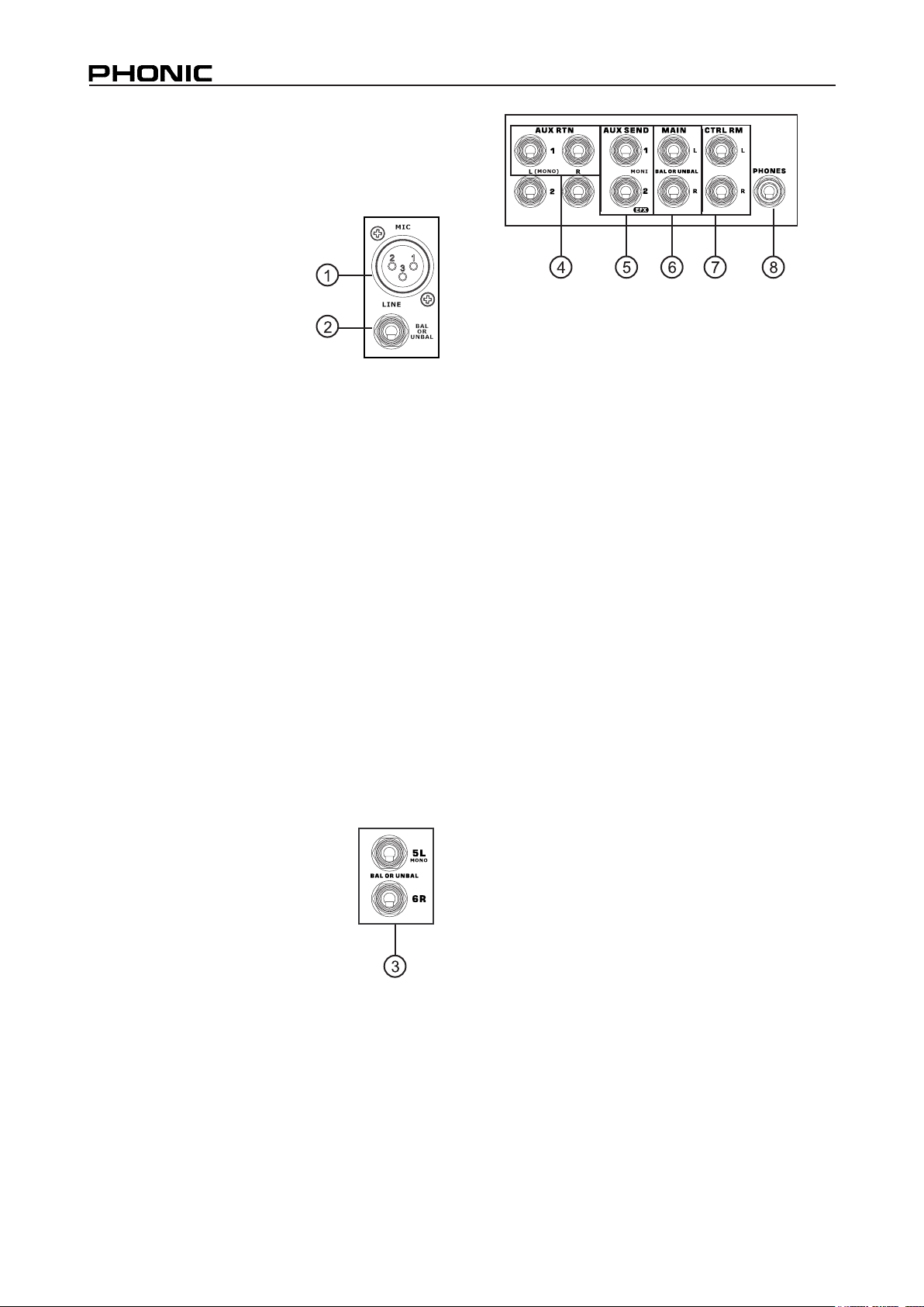
1. XLR Microphone Jacks
These jacks accept typical 3pin XLR inputs for balanced
and unbalanced signals.
They can be used in conjunction with microphones
– such as professional condenser, dynamic or ribbon
microphones - with standard
XLR male connectors, and
feature low noise preampliers, serving for crystal clear sound replication. The Helix Board 12
FireWire MKII mixers feature a total of four standard XLR microphone inputs.
NB. When these inputs are used with condenser
microphones, the Phantom Power should be activated.
However, when Phantom Power button is engaged, single
ended (unbalanced) microphones and instruments should
not be used on the Mic inputs.
4. Stereo AUX Return
These 1/4” TS inputs are for the return of audio
to the Helix Board 12 FireWire MKII mixer,
processed by an external signal processor. If
really needed, they can also be used as additional
stereo inputs, with a level control located on
the face of the mixer. The Stereo AUX Return
can also accept Mono signals, where plugging
the 1/4” phone jack of any device into the Left
input will cause the signal to be duplicated to the
Right input also (this does not work in reverse,
however). Signals processed by the built-in
digital effects processor are cut-off when any
1/4” phone jack is plugged into the AUX return 2.
2. Line Inputs
This input accepts typical 1/4” TRS or TS inputs,
for balanced or unbalanced signals. They can
be used in conjunction with various line level
devices, such as keyboards, drum machines,
electric guitars, and a variety of other electric
instruments.
3. Stereo Channels
The Helix Board 12 FireWire MKII
mixer features a couple of stereo
channels, thrown in for maximum
exibility. Each of these stereo
channels features two 1/4” TRS
phone jacks, for the addition of
various line level input devices,
such as electronic keyboards,
guitars and external signal
processors or mixers.
These Stereo Channels can also be used as
Mono channels, where the signal from any 1/4”
phone jack plugged into the Left stereo input
will be duplicated to the Right input due to the
miracle of jack normalizing (this does not work in
reverse, however).
5. AUX / Effects Send
These 1/4” TS outputs may be used to connect
to an external digital effect processor, or even to
an amplier and speakers (depending on your
desired settings), to the mixer. The AUX send is a
pre-fader signal, suitable for sending to monitors
to allow performers to monitor their music.
The EFX send signal is post-fader, suitable for
sending to external effect processors, and then
return back to the AUX returns.
6. Main L and R Outputs
These two ports will output the nal stereo
balanced line level signal sent from the main
mixing bus. The primary purpose of these jacks
is to send the main output to external devices,
which may include power ampliers (and in-turn,
a pair of speakers), other mixers, as well as a
wide range of other possible signal processors
(equalizers, crossovers, etcetera).
7. Control Room Outputs
These two 1/4” Phone Jack outputs feed the
signal altered by the Control Room / Submix
control on the face of the mixer. This output has
extensive use, as it can be used to feed the
signal from the mixer to an active monitor, for
the monitoring of the audio signal from within a
booth, among other possible uses.
6
HELIX BOARD 12 FIREWIRE MKII
Page 7
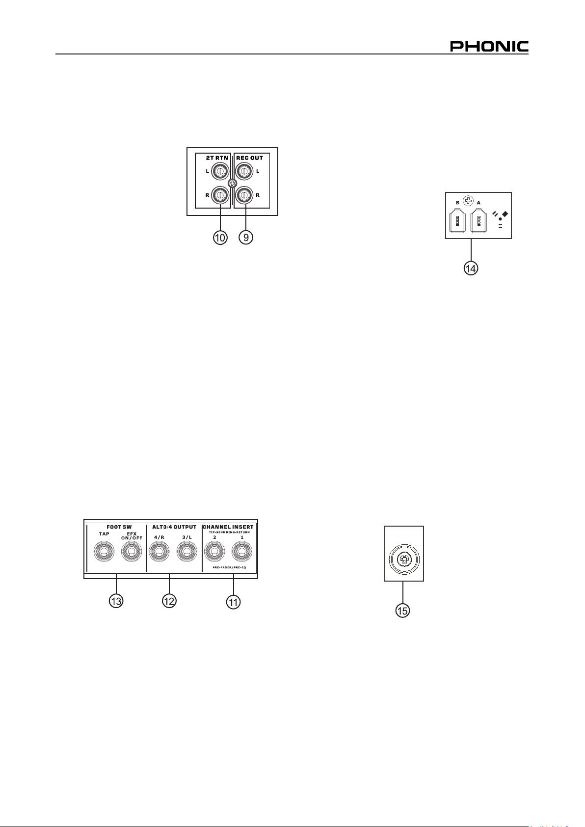
8. Phones
This stereo output port is suited for use with
headphones, allowing monitoring of the mix. The
audio level of this output is controlled using the
Control Room / Submix rotary control.
9. Record Out
These outputs will accommodate RCA cables,
able to be fed to a variety
of recording devices.
10. 2T Return
This stereo RCA input is used to connect the
mixer with external devices, such as tape and
CD players, and feeds the signal to the Main L-R
mixing bus.
Rear Panel
11. Channel Inserts
Located on the rear of the Helix Board, the primary
use for these TRS phone jacks is for the addition
of external devices, such as dynamic processors
or equalizers, to mono input channels 1 and 2.
This will require a Y cord that can send (pre-
fader and pre-EQ) and receive signals to and
from an external processor. On this connection,
the tip pin is for sending the signal, whereas the
ring pin is for return. The sleeve pin, on the other
hand, is the ground.
13. Foot Switch Jacks
These ports are for the inclusion of a foot switch,
used to remotely adjust properties of the builtin Digital Effect processor, to the mixer. The left
jack is used to adjust the tap delay properties,
whereas the right jack is used for turning the
effects on and off.
14. FireWire Connection
These two FireWire ports
are for connecting the Helix
Board to any PC or Macintosh
computer. They allow all 10
audio channels to be streamed
to a computer, and the 2 audio
channels of the computer
to be streamed back to the
Helix Board for monitoring
purposes. The signal of audio channels sent to
the computer is pre- or post-fader, depending on
the pre/post setting on each input channel. The
main left and right signal (also sent through the
FireWire interface) is a pre-main fader signal.
The returned FireWire signal can be utilized in
the FireWire Return section on the face of the
mixer.
15. Power Connector
This port is for the addition of a power cable
and supply, allowing power to be supplied to the
mixer. Please use the external power supply
that is included with this mixer only as using
other adaptors could damage the mixer. For a
replacement supply, contact your nearest Phonic
dealer.
AC IN
18.8V X2
8V X1
12. ALT 3-4 Output
The signal sent from these 1/4” outputs is fed
from the ALT 3-4 mixing bus, and can be used
in conjunction with a large array of devices,
including signal processors, other PA systems,
recording devices, and so on.
HELIX BOARD 12 FIREWIRE MKII
7
Page 8
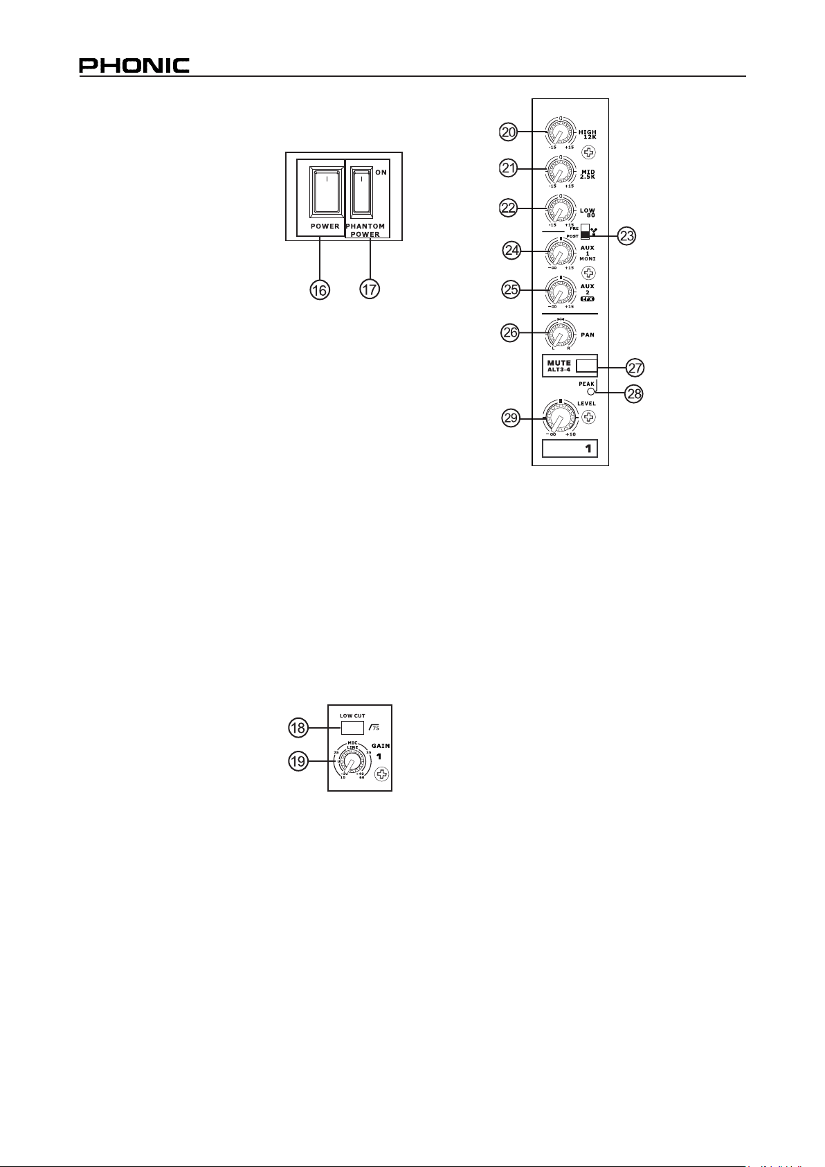
CONTROLS AND SETTINGS
Rear Panel
16. Power Switch
This switch is used to turn the
mixer on and off. Ensure you
turn all level controls down
before activating.
17. Phantom Power Switch
When this switch is in the on
position, it activates +48V
of phantom power for all microphone inputs,
allowing condenser microphones (well, the ones
that don’t use batteries) to be used on these
channels. Activating Phantom Power will be
accompanied by an illuminated LED above the
left channel Level Meter. Before turning Phantom
Power on, turn all level controls to a minimum to
avoid the possibility of a ghastly popping sound
from the speakers.
NB. Phantom Power should be used in conjunction with
balanced microphones. When Phantom Power is engaged,
single ended (unbalanced) microphones and instruments
should not be used on the Mic inputs. Phantom Power will
not cause damage to most dynamic microphones, however if
unsure, the microphone’s user manual should be consulted.
20. High Frequency Control
This control is used to give a shelving boost or
cut of ±15 dB to high frequency (12 kHz) sounds.
This will adjust the amount of treble included in
the audio of the channel, adding strength and
crispness to sounds such as guitars, cymbals,
and synthesizers.
Channel Controls
18. Low Cut Filter (75 Hz)
This button, located on
channels 1 through to 4,
will activate a low-cut / high-
pass lter that reduces all
frequencies below 75 Hz at
18 dB per Octave, helping
to remove any unwanted ground noise or stage
rumble.
19. Mic / Line Gain Control
This controls the sensitivity of the input signal
of the Microphone / Line input. The gain should
be adjusted to a level that allows the maximum
use of the audio, while still maintaining the
quality of the feed, based on the channel setup
instructions. This can be accomplished by
adjusting it to a level that will allow the peak
indicator occasionally illuminate. All 4 mono
channels feature this control.
21. Middle Frequency Control
This control is used to provide a peaking style
of boost and cut to the level of middle frequency
(2.5 kHz) sounds at a range of ±15 dB. Changing
middle frequencies of an audio feed can be rather
difcult when used in a professional audio mix, as
it is often more desirable to cut middle frequency
sounds rather than boost them, thereby soothing
overly harsh vocal and instrument sounds in the
audio.
22. Low Frequency Control
This control is used to give a shelving boost or
cut of ±15 dB to low frequency (80 Hz) sounds.
This will adjust the amount of bass included in
the audio of the channel, and bring more warmth
and punch to drums and bass guitars.
23. FireWire Pre / Post Switch
This switch is used to change the signal of
the corresponding channel that is sent to the
Computer via the FireWire interface between
that of a pre-EQ, pre-fader, pre-low cut to that of
a post-EQ, post-fader, post-low cut. In the uppermost position, the channel will be pre, and in the
lower position post.
8
HELIX BOARD 12 FIREWIRE MKII
Page 9
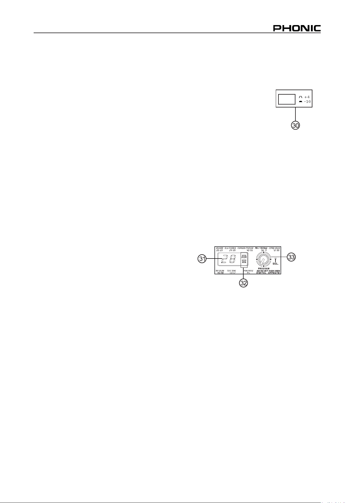
24. AUX 1 (Monitor) Control
This control allows the user to send the
corresponding signal to the AUX 1 output, which
can be used in conjunction with an amplier and
studio or stage monitors, or simply as an auxiliary
output for any means required. The control is
pre-fader, therefore any changes made to the
corresponding channel level control do not affect
the AUX 1 send signal.
25. AUX 2 (Effects) Control
This control alters the signal level that is sent
to the AUX 2 (or EFX) send output, which can
be used in conjunction with external signal
processors (this signal of which can be returned
to mixer via the AUX return input, or any stereo
input channel), or simply as an auxiliary output
for any means required. This control is postfader, therefore any changes made to the
corresponding channel level control are also
applied to the EFX signal. The EFX send signal
is also sent to the built-in effect processor for
providing effects to the main output and AUX 1
send, as required.
29. Level Control
This rotary control will alter the signal level that is
sent from the corresponding channel to the Main
or Alt. 3-4 mixing bus.
30. +4 / -10 Switch
This button, located on both
stereo input channels, is used
adjust the input sensitivity of
the corresponding channels,
which will adapt the mixer to
external devices which may
use different operating levels.
If the input source is -10 dBV (consumer audio
level), it is best to engage the switch, allowing
the signal to be heard. The +4 dBu level is
suitable for Professional Audio signals, which
are considerably higher than the consumer
level. However, if you are unsure of the source’s
operating level, we suggest leaving the switch
disengaged until you test the source’s signal.
You can then engage if necessary (if the level of
the input signal is obviously too low).
26. Pan / Balance Controls
This alternates the degree or level of audio that
the left and right side of the main mix should
receive. On mono channels, this control will
adjust the level that the left and right should
receive (pan), where as on a stereo channel,
adjusting the BAL control will attenuate the left
or right audio signals accordingly (balance).
27. Mute / ALT 3-4
This handy little button is basically a typical mute
button – effectively stopping any signal received
by the channel from being sent to the Main L/R
or AUX 2 send mixing buses – however it does
so much more. Pushing this button routes the
channel’s signal away from the Main L/R and to
its own “Alternate” stereo output (Alt 3-4), where
the signal can be used at will. If you wish to use
it to connect an amplier and speakers, or simply
patch it through to an unused input channel, you
can easily do so.
28. Peak Indicator
This LED indicator will illuminate when the device
hits high peaks, 6 dB before overload occurs. It is
best to adjust the gain of the channel so that the
PEAK indicator lights up on intervals only. This
will ensure a greater dynamic range of audio.
This LED will light up while the Mute button is
pushed in.
Digital Effect Section
31. Digital Effect Display
This 2-digital numeric display shows the program
number that is currently applied to your EFX
audio signal. When you rotate the Program
control, you can scroll through different program
numbers; however the display will revert back
to the original program if a new program is
not selected within a few seconds. For a list
of available effects, please observe the Digital
Effect Table.
32. Sig and Clip Indicators
Located within the Digital Effect Display are Clip
and Sig LEDs. The Sig LED will light up when
any signal is received by the effect processor,
and the Clip LED will light up shortly before
excessive signals are dynamically clipped. If the
Clip LED lights up too often, it may be advisable
to turn down the AUX 2/EFX control on one or all
input channels to ensure the signal level is not
excessive.
HELIX BOARD 12 FIREWIRE MKII
9
Page 10
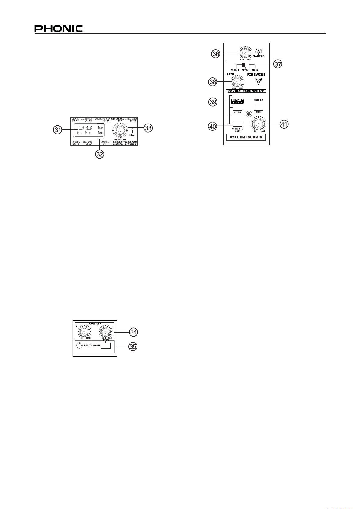
33. Program Control
This control is used to scroll through the various
effects. Turning the control clockwise will allow
users to ascend into higher program numbers,
and turning it counter-clockwise will allow users
to descend into lower program numbers. Pushing
this control will apply the new effect. When a tapdelay effect is selected, pressing this control will
allow users to select the tap-delay time.
By pushing the button several times, the effect
processor interprets the time between last two
pushes and remembers this as the delay time
– until the button is pushed again. This is kept
even after the power is turned off. When the tap
delay effect is selected, a small LED will ash
within the digital effect display window at the
selected intervals.
Master Section
34. AUX Stereo Return Controls
These controls adjust the signal level of audio
fed through to the AUX Stereo Return inputs,
which will be added to the MAIN L-R mix. The
AUX Return 2 control also acts as the builtin DSP Effect level control, when no device is
plugged into the AUX 2 Return jacks.
35. EFX to Monitor button
This button allows users to select the destination
of the AUX Return 2 signal. Pushing it in sends
the signal to the AUX Send 1 mixing bus.
36. AUX Send 1 Master Control
This control will adjust the nal output level for
the AUX send output, the signal of which is taken
from the AUX 1 from each input channel.
37. FireWire Source Select
This switch determines which of teh Helix
Board’s signals will be used for the 9th and 10th
channels sent through the FireWire interface
to the computer. Users can choose to send
the stereo signal from AUX 1/2, Alt 3/4 or the
Main mix through the FireWire interface to the
computer.
38. FireWire Trim Control and Indicator
This trim control can be used to adjust the level
of the outgoing FireWire signal from channel
9/10 (which will be received by the computer). If
the input signals received by your computer are
noticeably excessive, using this control could
help to attenuate the signal to an acceptable
degree. The accompanying LED will illuminate
when a connection is established through the
FireWire interface.
39. Control Room Buttons
Engaging any of these four buttons will enable you
to use the signal from any of the corresponding
sources to send to the Control Room mixing bus
and the LED Level Meter for level monitoring.
For instance, pressing FireWire & 2T Rtn button
will allow you to send the 2 Track Return signal
and the signal received through the FireWire
interface to the Control Room Outputs (the level
of which will be visible on the Level Meter), where
as the Main L-R will allow you to use the Main
Left/Right signal, the AUX 1 allows you to use
the AUX 1 signal, and the ALT 3-4 allows you to
use the “Alternate” stereo mix bus signal. You
can even use a combination of all these signals,
if need be.
10
HELIX BOARD 12 FIREWIRE MKII
Page 11
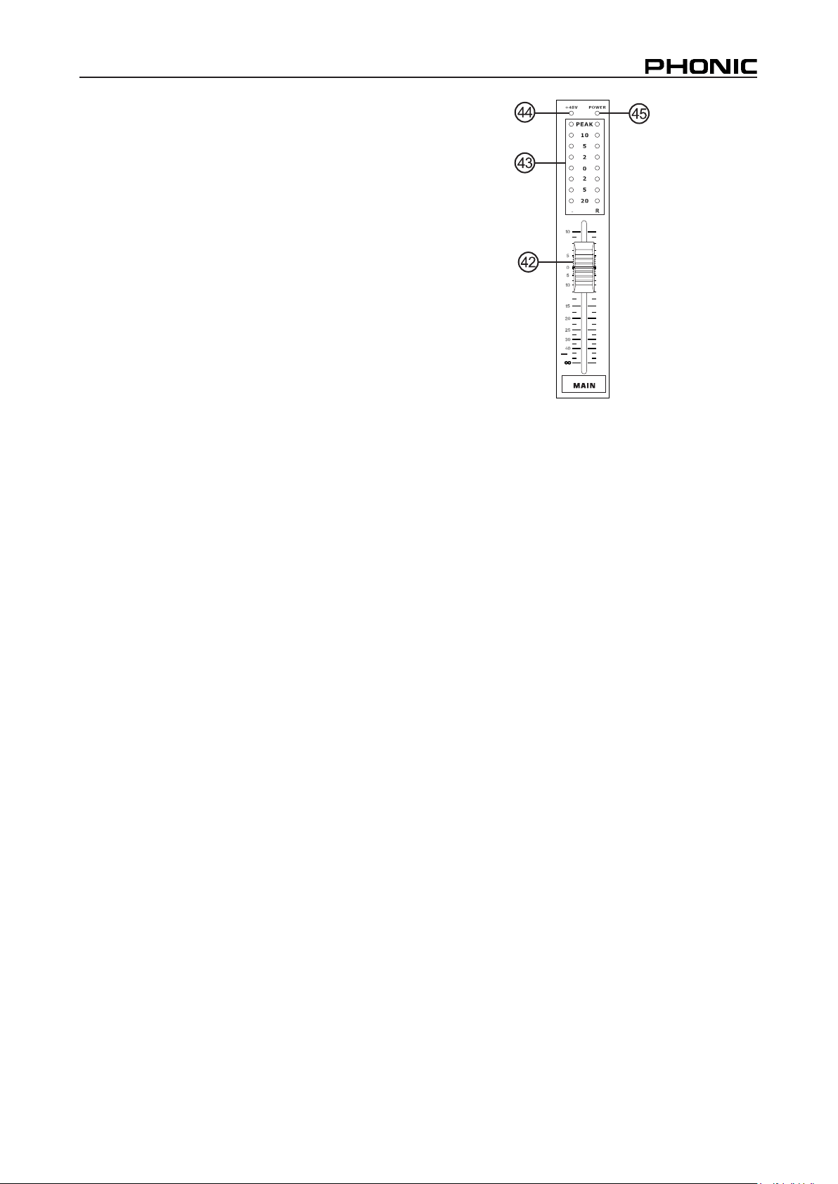
40. Assign to Main Button
When the “Assign to Main” button is engaged, the
FireWire/2T Return and Alternative 3-4 signals
can be selected by using the corresponding
buttons, and are, intern, sent to the Main L-R
and Control Room mixing buses via the Control
Room / Submix control. This can come in handy
when you want play a CD during intermission
in a live show, as this allows users to send the
signals from the FireWire interface, 2T RTN
and/or ALT 3-4 to the main left and right outputs.
If you have the Main L-R or AUX 1 buttons on
the Control Room Source section engaged, the
corresponding signals will not be sent to the
control room and headphones output by the use
of this button.
41. Control Room / Submix Control
This control is used to adjust the audio level of
the Control Room feed, which is sent to both the
Control Room outputs (for monitoring, acting as
side ll or other purposes) and Phones outputs
(to be used in conjunction with headphones
for monitoring purposes). It also acts as the
“Submix” control, which allows the user to adjust
the level of the signals selected by the Control
Room Source when the Assign to Main button
is engaged.
42. Main Level Fader
This 60mm fader is nal level control for the main
left and right audio feed, sent to the Main L and
R output.
43. Level Meter
The stereo 8-segment level meter gives an
accurate indication of when audio levels of the
selected Control Room source(s) reach certain
levels. It is suggested for the maximum use of
audio to set the various levels controls so that
the Peak LEDs ash only occasionally (and
perhaps it is better if you ensure the level stays
around a pinch below that).
44. +48 Indicator
The +48 Indicator illuminates whenever the
Phantom Power switch is activated.
45. Power Indicator
The Power Indicator will light up when the power
of the mixer is on.
HELIX BOARD 12 FIREWIRE MKII
11
Page 12
12
HELIX BOARD 12 FIREWIRE MKII
Page 13
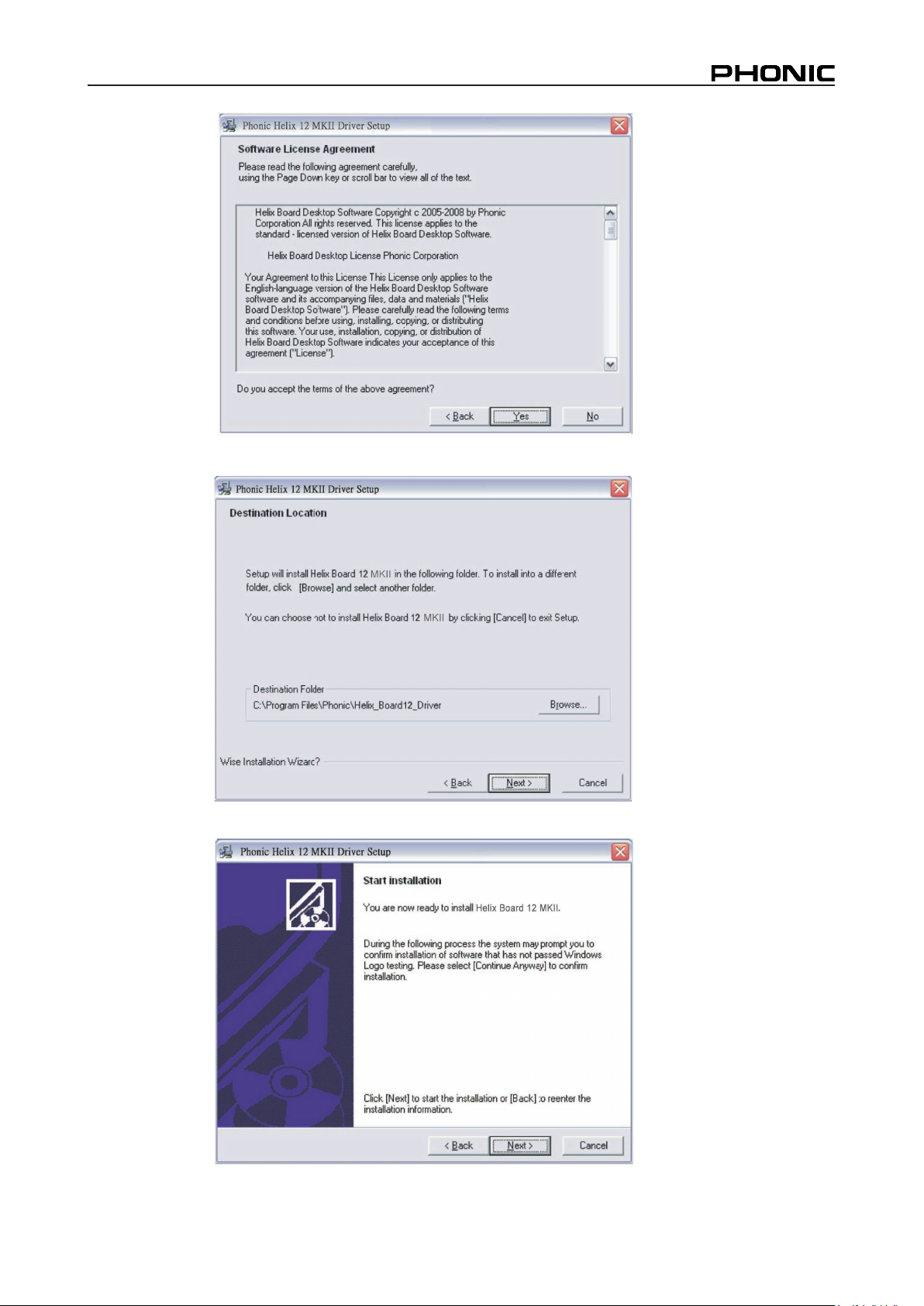
Read and accept the terms of the License Agreement and click "Yes" to continue.
ither select a new destination for the installation, or else click "Next" to accept the default directory
Click "Next" to begin the installation.
HELIX BOARD 12 FIREWIRE MKII
13
Page 14
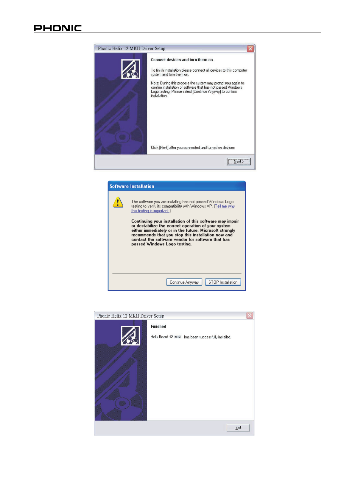
Connect the Helix Board FireWire MKII to the Computer and turn the power on.
If a message is displayed indicating that the software has not passed Windows Logo test, click Continue Anyway
14
After installation is complete, users are free to use the device as they wish.
HELIX BOARD 12 FIREWIRE MKII
Page 15
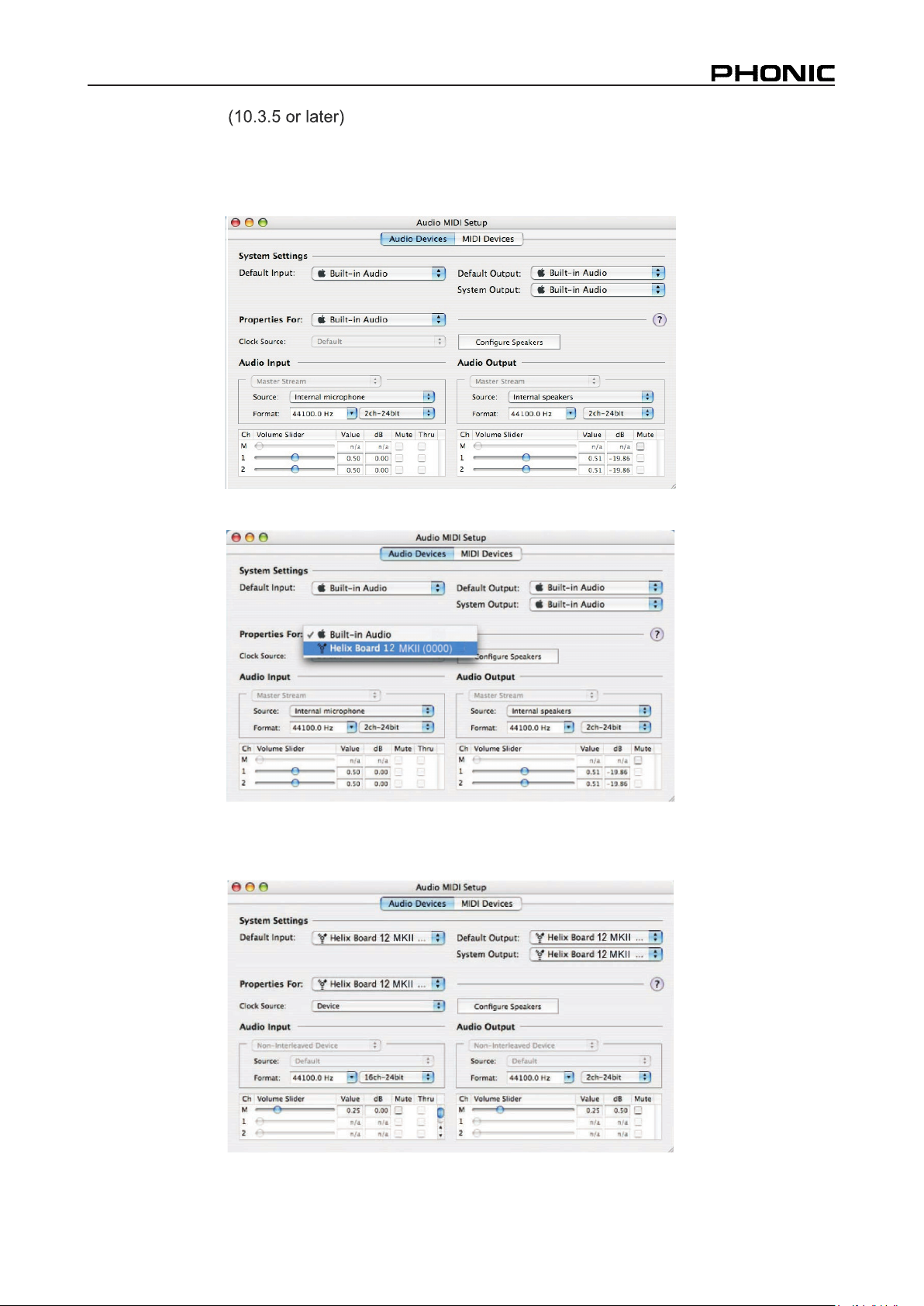
Macintosh OS X
The Helix Board 12 FireWire MKII works with the primary audio drivers of Macintosh OS X 10.3.5 and later. First verify
hat you are running Macintosh OS X 10.3.5 or above, then connect the Helix Board 12 FireWire MKII to a FireWire
t
to the
computer. T
Audio MIDI Setup icon.
o ensure your Helix Board 12 FireWire MKII is working,enter the Utilities folder and double-click the
port
Enter the
At the bottom of the window,
rate and clock source can be altered. Users may also opt to make th
/or output device.
Audio Devices section. From the "Properties for" pull-down tab, select Helix Board 12 FireWire MKII.
users can edit the setup of the Helix Board FireWire MKII. Properties such as sampling
e H
elix Board FireWire MKII their default input and
Mac users are able to use GarageBand Digital Audio Workstation Software, in conjunction with the Helix Board 12
FireWire MKII.
HELIX BOARD 12 FIREWIRE MKII
15
Page 16
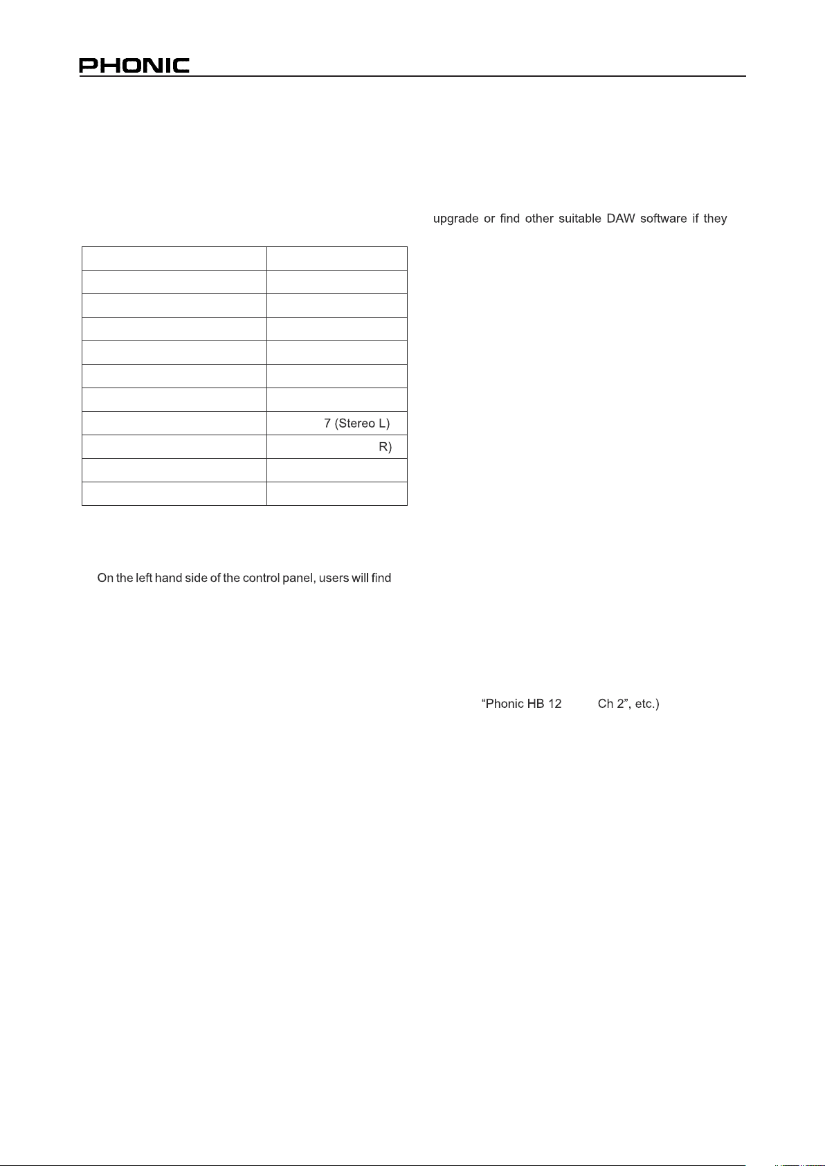
Channel Assignment
When using a Digital Audio Workstation on a PC,
and within the included Phonic Helix Board FireWire
control panel software, the following names have
been attributed to the input channels of the FireWire
mixer. They can be altered through the control panel
software included with the mixer.
FireWire Input Channel Name Mixer Channel
Phonic HB 12 MKII CH 1 Channel 1
Phonic HB 12 MKII CH 2 Channel 2
Phonic HB 12 MKII CH 3 Channel 3
Phonic HB 12 MKII CH 4 Channel 4
Phonic HB 12 MKII CH 5 Channel 5 (Stereo L)
Phonic HB 12 MKII CH 6 Channel 6 (Stereo R)
Phonic HB 12 MKII CH 7 Channel
Phonic HB 12 MKII CH 8 Channel 8 (Stereo
Phonic HB 12 MKII Main L User definable
Phonic HB 12 MKII Main R User definable
To alter an input channel s name on your computer,
open the Helix Board FireWire control panel software.
the settings categories. By clicking Input Channels ,
the main window will display the titles input channels.
You can then highlight the channel names and press
the Edit Channel Name button on the bottom of the
control window. A new window will appear that will
allow users to adjust the channel name.
If you
would like to use the
Helix Board Firewire MKII
as your default audio output device on you PC, simply
go into the Windows control panel, and select "Sound
and Audio Devices". Select the Audio tab, and use the
pull-down menu to select the Helix Board 12 FireWire
MKII from the list of
available output devices. The Helix
Board Firewire 12 MKII
can also be selected as the
default
output device for individual programs by editing
said
programs settings/options.
Cubase LE
Cubase LE is a fairly powerful program provided along
with the Helix Board FireWire mixer that allows users
to record, edit, delete, and alter their tracks. Please
note that only 4 tracks can be recorded at once with
the version of Cubase included, and users must
choose to record more tracks.
Installation
Insert the Cubase LE installation CD that came with
your mixer into the CD drive of your computer. Run
the installer. The serial number will be automatically
entered in when installing.
Setup
After successfully completing the installation process,
the following process must be followed to
work
1. Open the Cubase LE program.
2. Go to the Devices pull-down menu and
select Device Setup . On the left, select VST
Multitrack .
3.
From the ASIO Driver drop-down list, select Phonic
HB12 MKII Driver. A pop-up box will ask you if you
want to switch the ASIO drive
r. Click Switch. This
completes the basic installation and setup.
4. Activating audio tracks received from the Helix
Board mixer.
a. Go to the devices pull-down menu and
select VST Inputs . This will display the
various inputs ( Phonic HB 12 MKII Ch 1 ,
b. Activate 8 of these channels by clicking the
Active button located next to each channel
name. Please note, only 8 input channels
can be activated at any one time. This is a
limitation of Cubase LE, and if more input
channels are needed, we suggest upgrading
to a higher version of Cubase, or use other
DAW software.
5. For further instructions on the operation of
Cubase, please consult the user manual by
pressing F1 while the program is open.
If you wish to reset the Helix Board FireWire ASIO
driver, simply go to the devices pull-down menu
and select device setup . Simply click reset and
select the Phonic FireWire Audio driver. Click ok to
continue and the Helix Board 12 FireWire MKII should
once again become functional.
efficiently with the Helix Board 12 FireWire MKII mixer.
MKII
16
HELIX BOARD 12 FIREWIRE MKII
Page 17
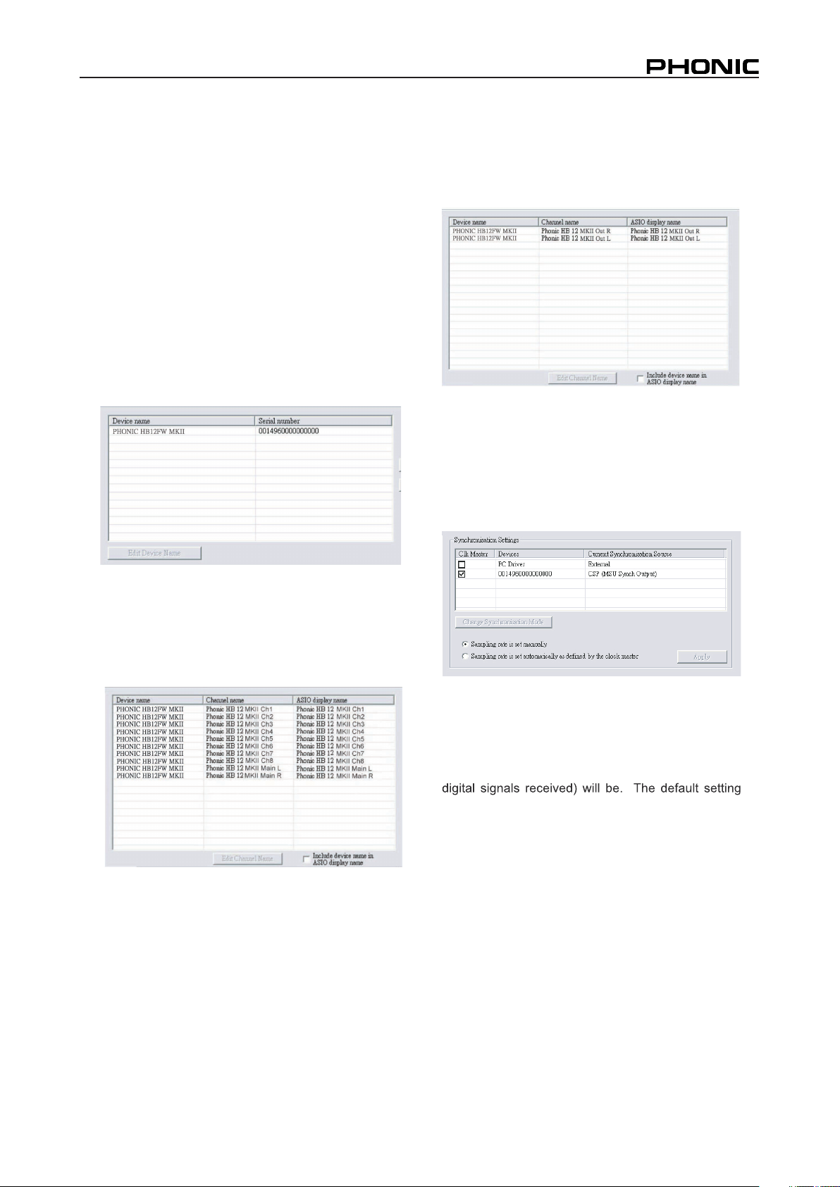
Helix Board Control Panel
The Helix Board FireWire MKII control panel can be
accessed at any time by entering choosing the
shortcut from your Programs menu. This program will
not only allow users to alter their device and channel
names and properties, but will also let them correct for
latency issues, change sampling rates, and so forth.
When opening the software, a number of options will
be available for users to select from, allowing them to
adjust the available properties.
Devices
In the Devices section, users are able to view and edit
the name of the Phonic MKII Devices connected to
their computer.
Output Channels
By entering the Output Channels section, users can
view and edit the names of the two output channels
from the computer to the Helix Board 12 Firewire MKII
mixer.
Synchronization
In the Synchronization section, users can adjust the
sampling rate and other synchronization properties.
Many of these adjustable properties, as they are, are
set for optimum performance and, unless you are sure
of what you need to change, are probably best left
alone.
Input Channels
The Input Channels section allows users to view and
edit the name of the various input channels received
from the FireWire input. For a list of default channel
names, please consult the table on page 16.
First off, the synch modecan be altered, though making
this alteration is not recommended for novice users.
The synch mode is basically the way the computer
determines what the clock source (ie. device that
your computer will use to determine the timing of all
for this feature is "CSP", meaning the Helix Board 12
FireWire MKII is the master clock source of the
device. The other options allow users to make the
Helix Board 12 FireWire follow the timing of which-
ever device is the clock source. Having two clock
sources has the potential to create very undesireable
audio, soit is best avoided. If the Helix Board 12
FireWire MKII is the only piece of digital audio equip-
ment attached to the computer, there is no reason this
option should be changed.
HELIX BOARD 12 FIREWIRE MKII
17
Page 18
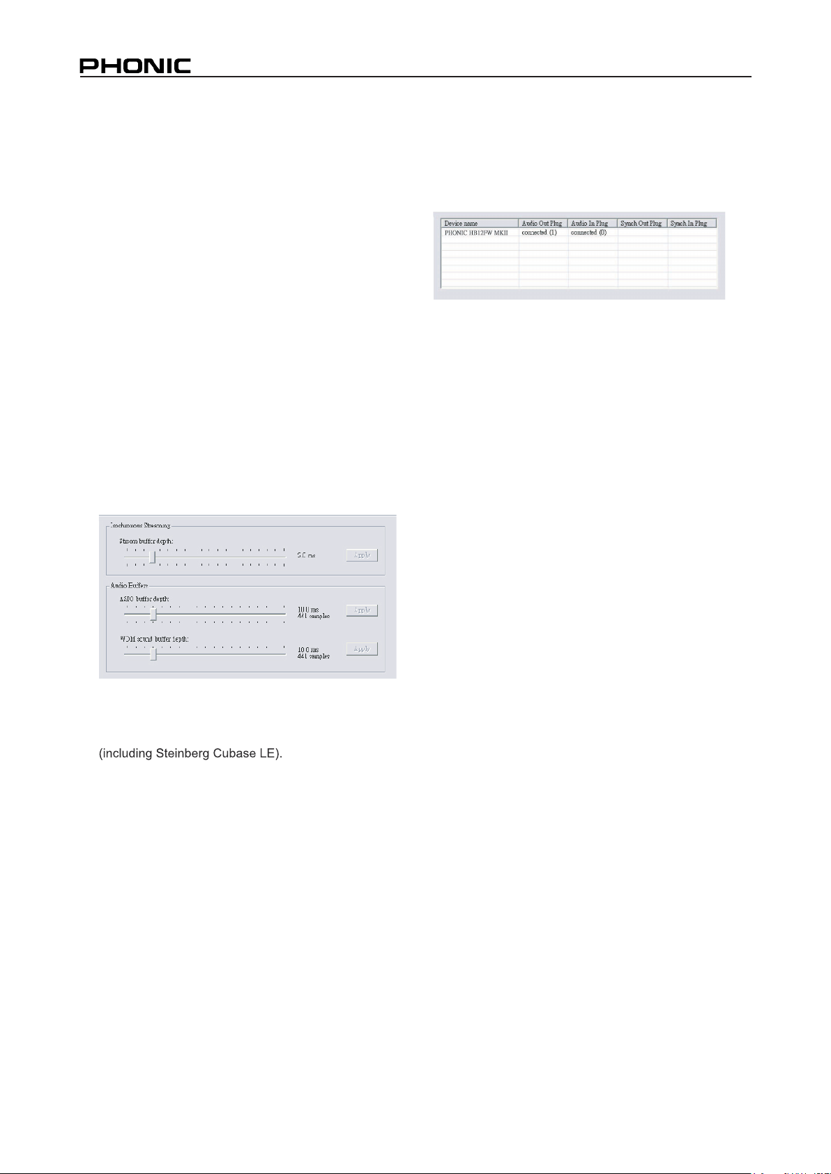
Users are also able to change between automatic and
manual sampling rate settings. W hen the sampling
rate is manually set, users can select between
sampling rates of 44.1, 48.0, 88.2 and 96.0 kHz per
second. Many devices have sampling rates that do
not surpass 44.1 kHz per second, therefore, when
using multiple digital devices, users are advised not to
exceed this level unless they are sure the secondary
device s sampling rate can .
Settings
Users are able to adjust various buffer times in the
Settings section.
The Stream Buffer Depth is adjustable between 0.5
and 20 milliseconds. It adjusts the buffer used when
streaming a signal from the Helix Board 12 FireWire.
If the depth is set too high, an obvious latency will
become evident. If the depth is too low, various clicks
and pops may become obvious. It is best to set the
Stream Buffer Depth to a level that allows users to get
the lowest latency, while still maintaining an optimal
performance. The default settings are ideal for most
computers.
Streams
In the Streams section, the Helix Board 12 F ireWire
device properties can be viewed. Each input and
output stream can be scrutinized, and the isochronous
stream number and its supported sampling rates can
be viewed.
The ASIO Buffer Depth is adjustable between 4 and 40
milliseconds. This allows users to adjust the latency
of the stream received by ASIO driver-based software
The WDM (Windows Driver Model) Sound Buffer
Depth is adjustable between 4 and 40 milliseconds.
This allows users to adjust the latency of the stream
received by WDM based programs.
Also in this section, users are able to view their "drop
out statistics", where the number of times the FireWire
connection has been interupted can be viewed.
18
HELIX BOARD 12 FIREWIRE MKII
Page 19
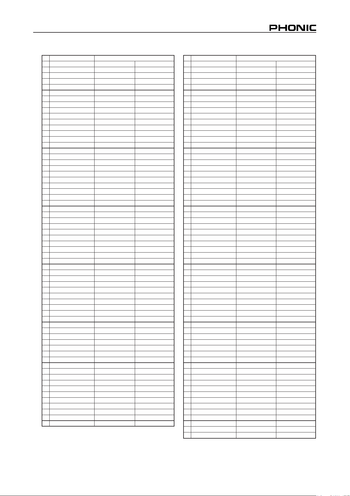
DIGITAL EFFECT TABLE
NO PROGRAM NAME PARAMETER SETTING
ROOM REV-TIME EARLY LEVEL
00 COMPACT ROOM 1 0.05 100
01 COMPACT ROOM 2 0.4 0
02 SMALL ROOM 1 0.45 100
03 SMALL ROOM 2 0.6 90
04 MID ROOM 1 0.9 100
05 MID ROOM 2 1 50
06 BIG ROOM 1 1.2 100
07 TUNNEL 3.85 100
HALL REV-TIME EARLY LEVEL
08 JAZZ CLUB 0.9 90
09 SMALL HALL 1 1.5 72
10 SMALL HALL 2 1.75 85
11 SPRING HALL 1.9 98
12 MID HALL 1 2.3 100
13 MID HALL 2 2.45 80
14 RECITAL HALL 2.7 96
15 BIG HALL 2 3.3 88
PLATE REV-TIME HPF
16 SMALL PLATE 0.9 0
17 TAIL PLATE 1.2 20
18 MID PLATE 1 1.3 0
19 MID PLATE 2 2.2 0
20 REVERSE PLATE 2.25 42
21 LONG PLATE 1 2.6 80
22 LONG PLATE 2 3 625
23 LONG PLATE 3 4.2 0
DELAY (stereo) DELAY AVERG. R-LEVEL
24 SHORT DELAY 1 0.07 60
25 SHORT DELAY 2 0.14 60
26 PING PONG DELAY 0.11 55
27 MID DELAY 1 0.15 55
28 MID DELAY 1 0.3 60
29 SHORT DELAY 1 (MONO) 0.06 100
30 MID DELAY 1 (MONO) 0.13 100
31 LONG DELAY 1 (MONO) 0.18 100
CHORUS LFO DEPTH
32 SOFT CHORUS 0.2 56
33 SOFT CHORUS 2 0.5 70
34 SOFT CHORUS 3 0.8 75
35 WARM CHORUS 1.8 85
36 WARMER CHORUS 1 3.2 80
37 WARMER CHORUS 2 5.2 45
38 WARMER CHORUS 3 7.8 52
39 HEAVY CHORUS 9.6 48
FLANGER LFO DEPTH
40 CLASSIC FLANGER 1 0.1 44
41 CLASSIC FLANGER 2 0.3 63
42 GENTLE FLANGER 0.6 45
43 WARM FLANGER 1.6 60
44 MODERN FALANGER 1 2 85
45 MODERN FALANGER 2 2.8 80
46 DEEP FALANGER 1 4.6 75
47 DEEP FALANGER 2 10 60
PHASE
R LFO DELAY
48 CLASSIC PHASER 1 0.1 3.6
49 CLASSIC PHASER 2 0.4 2.6
50 COOL PHASER 1.4 0.7
51 WARM PHASER 3.2 0.3
52 HEAVY PHASER 1 5 1.2
53 HEAVY PHASER 2 6 2.8
54 WILD PHASER 1 7.4 0.8
55 WILD PHASER 2 9.6 4.8
NO PROGRAM NAME PARAMETER SETTING
PAN SPEED TYPE
56 SLOW PAN 0.1 R-->L
57 SLOW PAN 1 0.1 R<-->L
58 SLOW PAN 2 0.4 R-->L
59 MID SHIFT 0.8 R<-->L
60 MID SHIFT 1 1.2 L-->R
61 MID SHIFT 2 1.8 L-->R
62 MID SHIFT 3 1.8 R-->L
63 FAST MOVE 3.4 R<-->L
TREMOLO SPEED MODE-TYPE
64 LAZY TREMOLO 0.8 TRG
65 VINTAGE TREMOLO 1.5 TRG
66 WARM TREMOLO 2.8 TRG
67 WARM TREMOLO 1 4.6 TRG
68 HOT TREMOLO 6.8 TRG
69 HOT TREMOLO 1 9.6 TRG
70 CRAZY TREMOLO 1 15 TRG
71 CRAZY TREMOLO 2 20 TRG
DELAY+REV REV DELAY
72 DELAY+REV 1 1 1
73 DELAY+REV 2 2 2
74 DELAY+REV 3 3 3
75 DELAY+REV 4 4 4
76 DELAY+REV 5 5 5
77 DELAY+REV 6 6 6
78 DELAY+REV 7 7 7
79 DELAY+REV 8 8 8
CHORUS+REV REV CHORUS
80 CHORUS+REV 1 1 1
81 CHORUS+REV 2 2 2
82 CHORUS+REV 3 3 3
83 CHORUS+REV 4 4 4
84 CHORUS+REV 5 5 5
85 CHORUS+REV 6 6 6
86 CHORUS+REV 7 7 7
87 CHORUS+REV 8 8 8
FLANGER+REV REV FLANGER
88 FLANGER+REV 1 1 1
89 FLANGER+REV 2 2 2
90 FLANGER+REV 3 3 3
91 FLANGER+REV 4 4 4
92 FLANGER+REV 5 5 5
93 FLANGER+REV 6 6 6
94 FLANGER+REV 7 7 7
95 FLANGER+REV 8 8 8
G
ATED-REV RELEASE REV
96 GATED-REV-1 9 0.02 TAIL PLATE
97 GATED-REV-2 10 0.2 TAIL PLATE
98 GATED-REV-1 9 0.02 REVERSE PLATE
99 GATED-REV-2 10 0.5 REVERSE PLATE
TAP DELAY FB LEVEL RANGE
A0 TAP DELAY 0 100mS - 2.7S
A1 TAP DELAY 10 100mS - 2.7S
A2 TAP DELAY 20 100mS - 2.7S
A3 TAP DELAY 30 100mS - 2.7S
A4 TAP DELAY 40 100mS - 2.7S
A5 TAP DELAY 50 100mS - 2.7S
A6 TAP DELAY 60 100mS - 2.7S
A7 TAP DELAY 70 100mS - 2.7S
A8 TAP DELAY 80 100mS - 2.7S
TEST TONE FREQUENCY SHAPE
T0 LOW FREQUENCY 100Hz SINEWAVE
T1 MID FREQUENCY 1kHz SINEWAVE
T2 HIGH FREQUENCY 10kHz SINEWAVE
PN PINK NOISE 20Hz~20kHz
HELIX BOARD 12 FIREWIRE MKII
19
Page 20
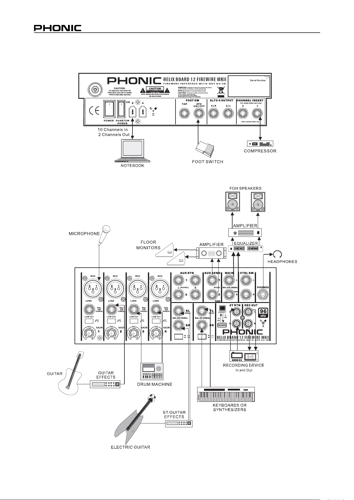
APPLICATION
AC IN
16.8V X2
8V X1
Multi-track
Recording
Live Sound with Multi-Track Recording
20
HELIX BOARD 12 FIREWIRE MKII
Page 21
AC IN
16.8V X2
8V X1
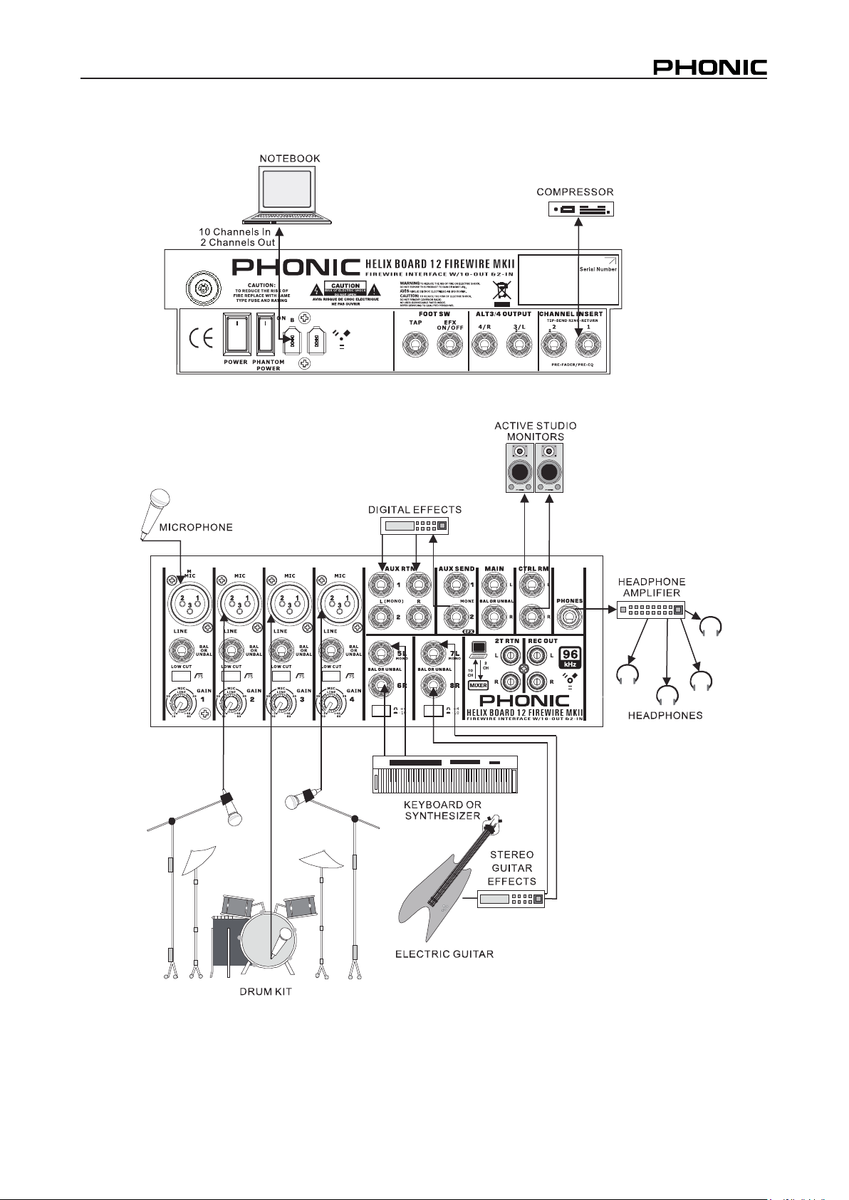
Studio Recording and Monitoring
Multi-track
Recording
HELIX BOARD 12 FIREWIRE MKII
21
Page 22
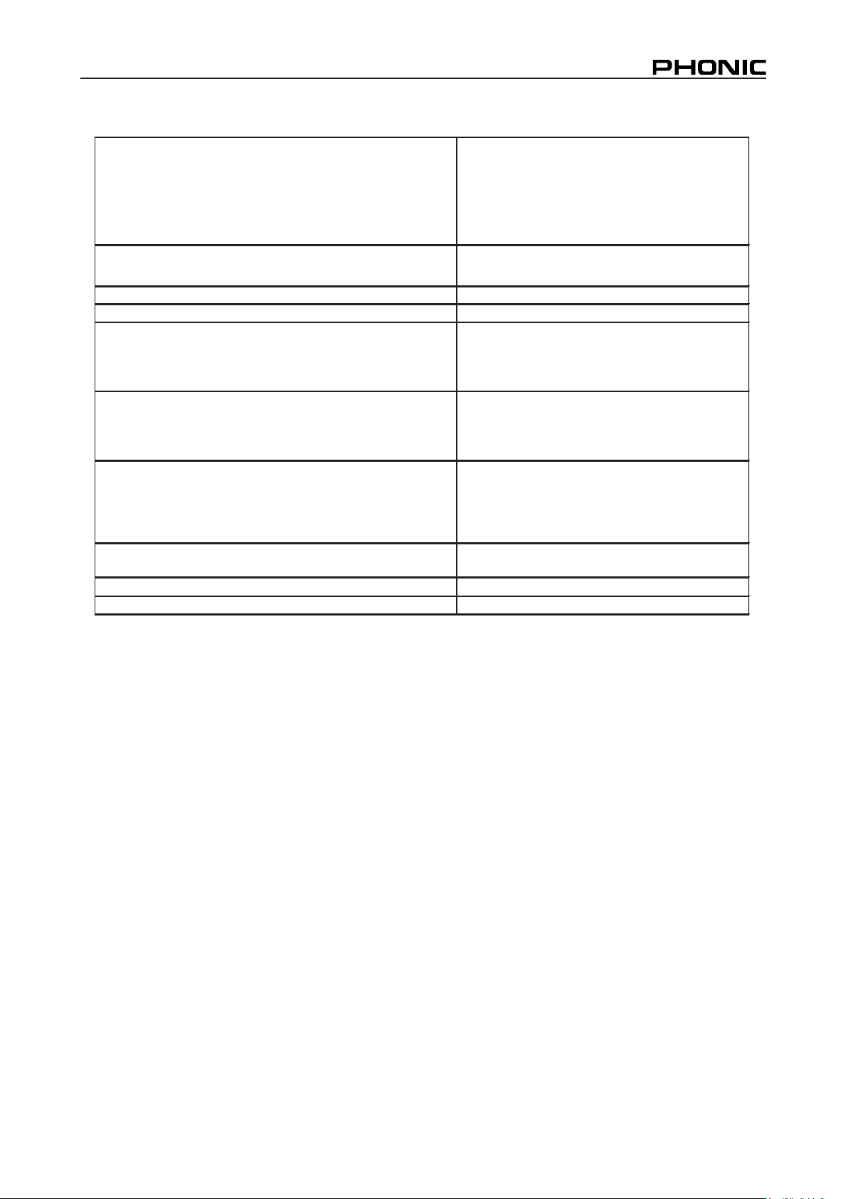
SPECIFICATIONS
g
y
)
)
Helix Board 12 Firewire MKII
Inputs
Total channels 6
Balanced Mono Mic/Line channel 4
Balanced Stereo Line Channel 2
Aux return 2 stereo
2T input Stereo RCA
Outputs
Main L/R stereo 2 x 1/4" TRS, Bal.
ALT 3-4 2 x
Rec out with trim control Stereo RCA
CTRL RM L/R 2 x 1/4" TS
Phones 1
FireWire Interface 10 out & 2 in, 24-bit / 96 kHz
Channel Strips 6
Insert Points 2
Aux send 2
Pan/Balance control Yes
Volume Controls Rotary
Master Section
Stereo aux returns 2
Effects return to monitor 1
Control room/Phones Level Control Yes
Faders Main L/R, 60mm fader
Meterin
Number of channels 2
Segments 8
Phantom Power Suppl
Switches Master
Effect processor 100 pr ograms plus tap dela y; foot switch
FrequencyResponse(Mic input to anyoutput
20Hz ~ 60KHz +0/-1 dB
20Hz ~ 100KHz +0/-3 dB
Crosstalk
channel in to main L/R outputs
Channel fader down, other channels at unity <-90 dB
(1KHz @ 0dBu, 20Hz to 20KHz bandwidth,
1/4" TS, Unbal.
+48VDC
(effect on /off, tap)
22
HELIX BOARD 12 FIREWIRE MKII
Page 23
Noise
y
(Any
(
)
)
(20Hz~20KHz; measured at main output,
Channels 1-4 unit gain; EQ flat; all channels on main
mix; channels 1/3 as far left aspossible, channels 2/4
Master @ unity, channel fader down -86.5 dBu
Master @ unity, channel fader@ unit
-84 dBu
S/N ration, ref to +4 >90 dB
Microphone Preamp E.I.N. (150 ohms terminated ,
<-129.5 dB m
max gain )
THD
CMRR
output, 1KHz@ +14dBu, 20Hz to 20KHz,
1 KHz@ -60dBu, Gain at maximum
<0.005%
80 dB
Maximum Level
Mic preamp input +10 dBu
All other input +22 dB u
Balanced output +28 dBu
Impedance
Micpreampinput 2 K ohms
All other input(except insert
10 K ohms
RCA 2T output 1.1 K ohms
Equalization 3-ban d, +/-15 dB
Low EQ 80 Hz
Mid EQ 2.5 KHz
Hi EQ 12 KHz
Low cut filter 75Hz (-18dB/oct)
Power Requirement (external power supply ,
100VAC, 120VAC, 220~240VAC, 50/60Hz
depe nds on region )
Net Weight 2.9 kg (6 lbs)
Dimensions(WxHxD
)
245.4x86x271.3 mm (9.7"x3.4"x10.7")
HELIX BOARD 12 FIREWIRE MKII
23
Page 24
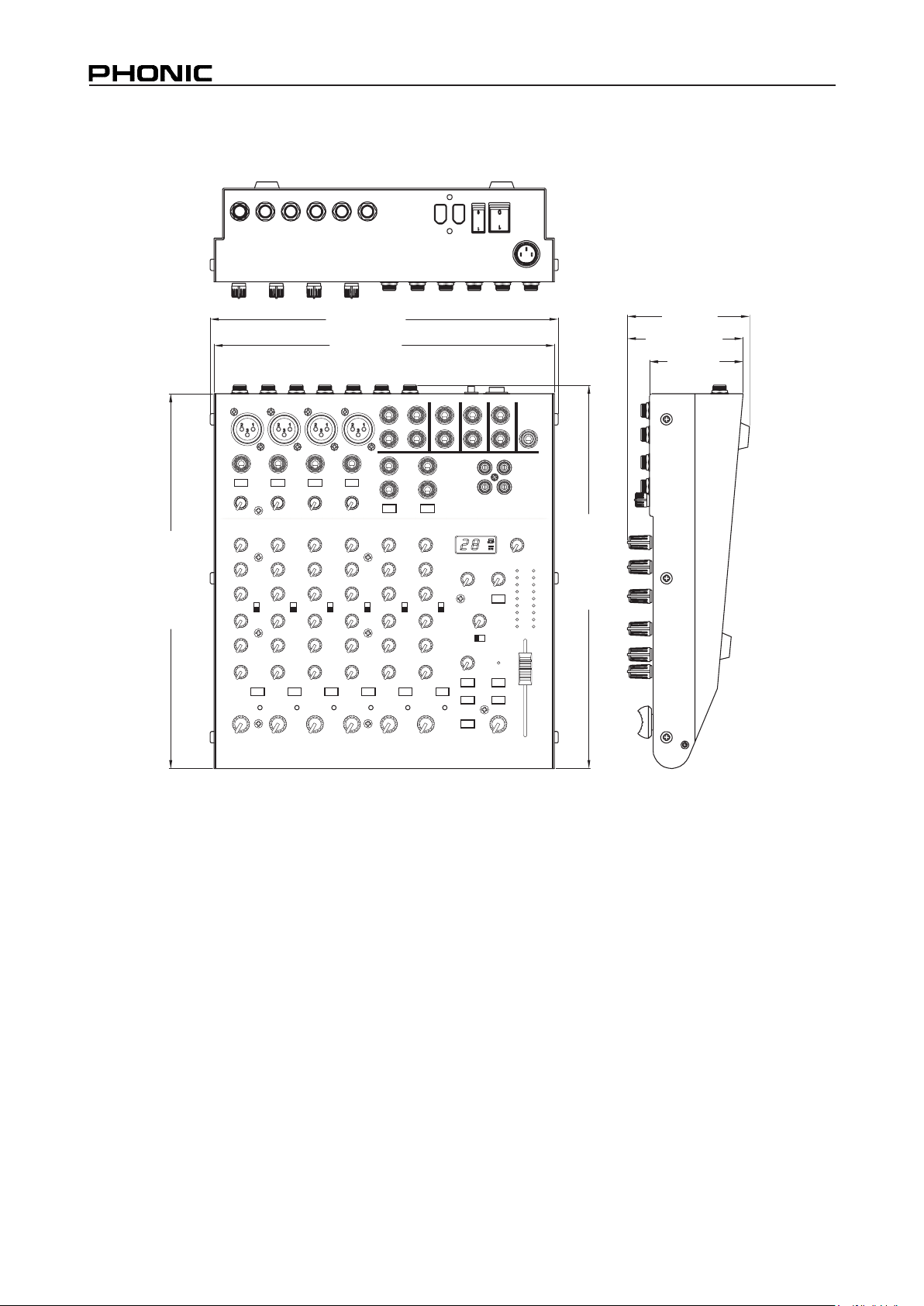
DIMENSIONS
245.4/9.7
240/9.5
86/3.4
81.5/3.21
66/2.6
.0
1
/3.0 672
.
0
1/3.
4 4
62
All measurements are shown in mm/inch.
24
HELIX BOARD 12 FIREWIRE MKII
Page 25
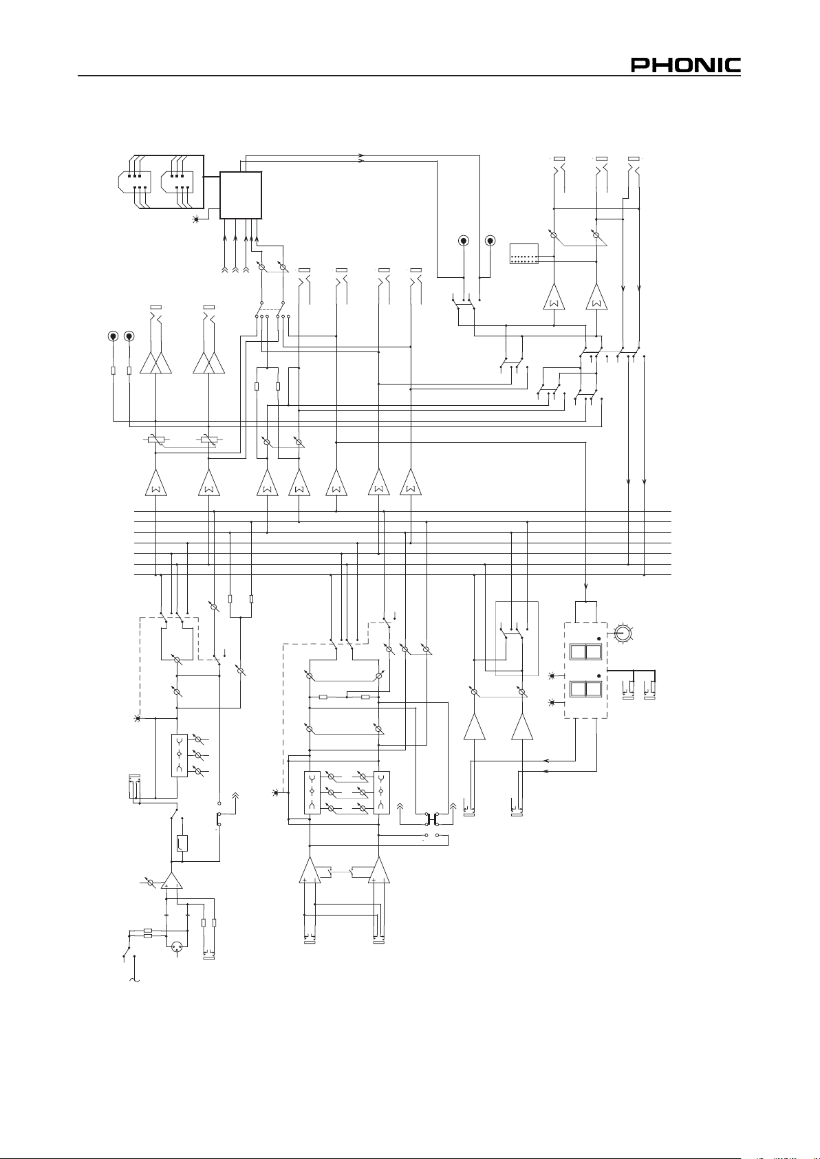
BLOCK DIAGRAM
)
4
F
O1(
MAIN R
X
I
M
T
LA
ALT 3
AUX1 L
ALT 4
XIMNIAM
AUX2
XIM2XUA
XI
M
1XUA
LEN
NA
HCON
OM
MAIN L
AUX1 R
FON
O
MLH
T
IW1NT
R
XUA .N
O
ITCN
U
TCE
F
F
E
For
2
N
TRXU
A .
N
RU
T
ER
2NTRylnO
E
RIWE
RIF
O
T8
/
6
HC
ERIWE
RIF
O
T7
/
5H
C
ER
I
W
R
I
F
O
T7
/5H
C
ERIW
ER
I
FOT
4
~
1
H
C
E
RIW
E
RI
F
O
T4~1H
C
E
RIW
E
RI
F
O
T
8
/
6
H
C
NI
ENIL
GIS
ERIWERIF
2XUA
1
X
UAO
T
WO
L
)7/
5
(L
LENNAHCOE
R
E
T
S
TSOP/
E
RP
1X
U
A
RNIAM
TSOP/ERP
R
/LNIA
M
N
IAG
XIMBUS
MIRT
ETUM/K
A
EP
2X
U
A
R
MRLRT
C
O
LD
I
MI
H
0
8
K
21
K
5
.
2
FFO/NOTC
E
FFE
z
H5
7
F
P
H
TU
CW
O
L
)4/3TLA(ETUM
E
T
UM
/
K
A
E
P
NI
CI
M
23
1
.L
A
B
LNTR
T
2
O
LDI
M
I
H
08K21
K5.2
.
DOM
E
R
I
WERIF
SE
NO
HP
T2&ERIWERIF
0
1-/4+
O
LDIMIH
0
8
K21
K5
.
2
QE
1X
U
A
2/
1
N
T
R
4
/3T
L
A
DI
M
X
F
E
-
100
T
U
O4TLA
)
8/
6
(
R
R
N
A
P
RNTR
T
2
2*K
C
AJ4
9
31
1
2
3
4
5
6
KAEP
501
02
5
2
2
0
V57
7
.0
=
uBd0
M
R
L
R
T
C
TR
E
S
N
I
)2,1
H
C
n
Oyln
O
(
TUO)
XF
E(2XU
A
KAE
P
L
T
UO
C
ER
L
E
VEL
2-1XUA/4-3TLA/NIAM
RTUOCER
N
I
AMOTNGISS
A
YA
LEDPAT
LNIAM
HG
I
H
).
L
E
SH
SU
P(M
AR
G
OR
P
1XUA
TUO1
X
UA
TU
O
3T
L
A
R
E
TU
P
MOC
O
T
123
456
LEVEL
2/1N
T
R
X
UA
L
REWOPMO
T
NAHP
)
H
CT
IW
S
LA
B
OL
G(
)4/
3T
LA(
E
TUM
.RWP
.
HP
L
M
R
LR
TC
HELIX BOARD 12 FIREWIRE MKII
25
Page 26

6103 Johns Road #7
Page 27

 Loading...