

Page 1
AM642DP
User's Manual
AM642D
AM642DP
AM642D USB
Manual del Usuario
Page 2

English Español
AM642D
AM642DP
AM642D USB
COMPACT MIXERS
MEZCLADORAS COMPACTAS
ENGLISH ........................................I
ESPAÑOL ......................................II
APPENDIX ...................................III
V1.0 07/07/2014
Page 3

USER'S MANUAL
CONTENTS
INTRODUCTION...............................................1
FEATURES..................................................1
COMPUTER CONNECTION (USB MODEL)..........................1
GETTING STARTED...................................2
CHANNEL SETUP .............................................2
MAKING CONNECTIONS...........................................3
Inputs and Outputs...........................................3
Rear Panel ...............................................4
CONTROLS AND SETTINGS.........................................5
Rear Panel......................................................5
English
Channel Controls.............................................................5
Digital Effect Processor.................................................6
Master Section................................................7
USB Player....................................................9
AM642D USB Only..........................................................9
SPECIFICATIONS.......................................................10
APPENDIX
DIMENSIONS...............................................1
DIGITAL EFFECT TABLE.......................................................1
APPLICATION.....................................................2
BLOCK DIAGRAMS...................................................................3
Phonic preserves the right to improve or alter any information within this
document without prior notice
Page 4
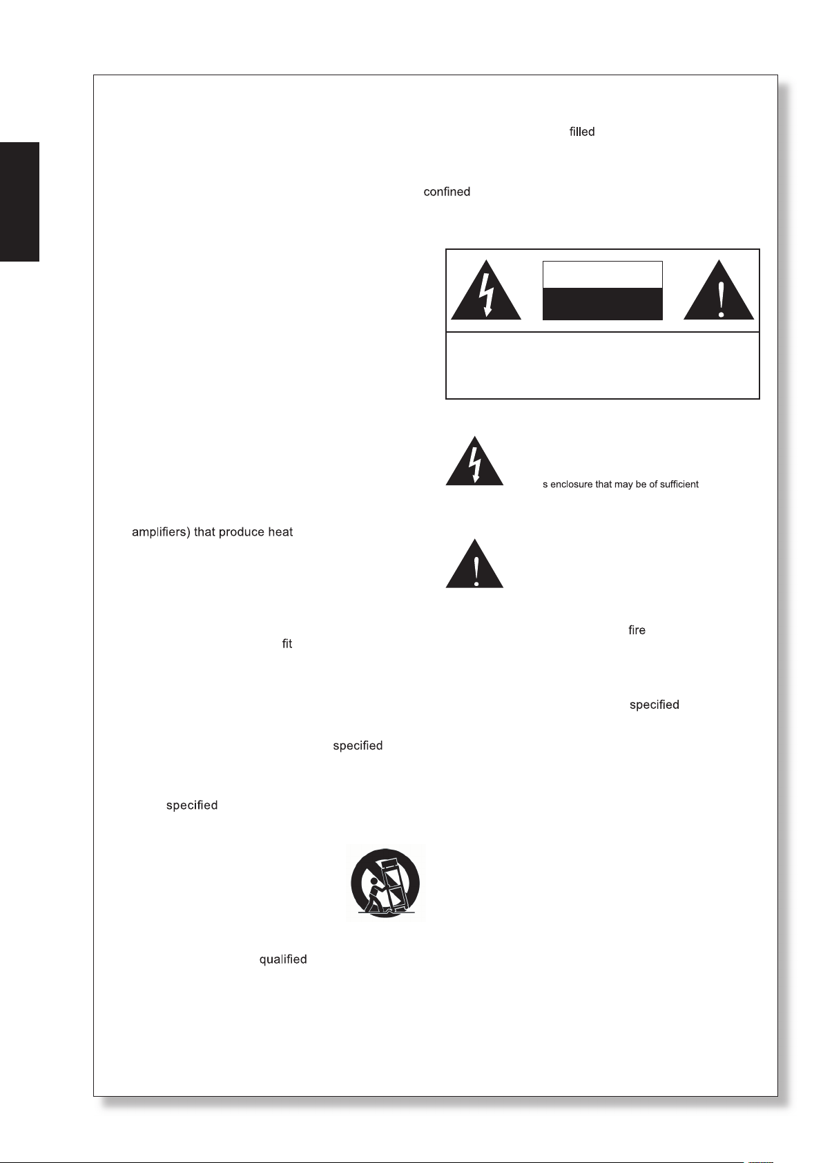
IMPORTANT SAFETY INSTRUCTIONS
English
The apparatus shall not be exposed to dripping or splashing and that no objects
with liquids, such as vases,
shall be placed on the apparatus. The MAINS plug is used as the disconnect device, the disconnect device shall
remain readily operable.
Warning: the user shall not place this apparatus in the
area during the operation so that the mains switch
can be easily accessible.
1. Read these instructions before operating this
apparatus.
2. Keep these instructions for future reference.
CAUTION
RISK OF ELECTRIC SHOCK
DO NOT OPEN
3. Heed all warnings to ensure safe operation.
4. Follow all instructions provided in this document.
5. Do not use this apparatus near water or in locations
where condensation may occur.
CAUTION: TO REDUCE THE RISK OF ELECTRIC SHOCK,
DO NOT REMOVE COVER (OR BACK)
NO USER SERVICEABLE PARTS INSIDE
REFER SERVICING TO QUALIFIED PERSONNEL
6. Clean only with dry cloth. Do not use aerosol or liquid
cleaners. Unplug this apparatus before cleaning.
7. Do not block any of the ventilation openings. Install
’
in accordance with the manufacturer
s instructions.
8. Do not install near any heat sources such as radiators,
The lightning flash with arrowhead symbol, within an
equilateral triangle, is intended to alert the user to the
“
presence of uninsulated
product
’
magnitude to constitute a risk of electric shock to persons.
dangerous voltage” within the
heat registers, stoves, or other apparatus (including
.
9. Do not defeat the safety purpose of the polarized or
grounding-type plug. A polarized plug has two blades
with one wider than the other. A grounding type plug
The exclamation point within an equilateral triangle is in-
tended to alert the user to the presence of important operat-
ing and maintenance (servicing) instructions in the literature
accompanying the appliance.
has two blades and a third grounding prong. The wide
blade or the third prong is provided for your safety. If
the provided plug does not
into your outlet, consult
WARNING: To reduce the risk of or electric shock, do
not expose this apparatus to rain or moisture.
an electrician for replacement of the obsolete outlet.
10. Protect the power cord from being walked on or
pinched particularly at plug, convenience receptacles,
and the point where they exit from the apparatus.
11. Only use attachments/accessories
by the
manufacturer.
12. Use only with a cart, stand, tripod, bracket, or
table
by the manufacturer, or sold with
the apparatus. When a cart is used, use caution
when moving the cart/apparatus
combination to avoid injury from tipover.
13. Unplug this apparatus during lighting
storms or when unused for long
periods of time.
14. Refer all servicing to
service personnel.
Servicing is required when the apparatus has been
damaged in any way, such as power-supply cord or
plug is damaged, liquid has been spilled or objects
have fallen into the apparatus, the apparatus has
been exposed to rain or moisture, does not operate
normally, or has been dropped.
CAUTION: Use of controls or adjustments or performance
of procedures other than those
may result in
hazardous radiation exposure.
Page 5

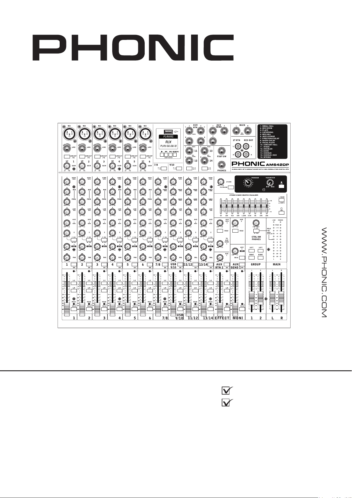
Introduction
Thank you for choosing one of Phonic’s many
quality compact mixers. The brand new AM642D,
AM642DP and AM642D USB mixers – designed
by the ingenious engineers that have created a
variety of mixers fantastic in style and performance
in the past – display similar prociency that previous
Phonic products have shown; with more than a few
renements, of course. Featuring full gain ranges,
amazingly low distortion levels, and incredibly wide
dynamic ranges, these amazing mixers are bound to
make a big splash in the world of mixing.
We know how eager you are to get started – wanting
to get the mixer out and hook it all up is probably your
number one priority right now – but before you do, we
strongly urge you to take a look through this manual.
Inside, you will nd important facts and gures on the
set up, use and applications of your brand new mixer.
If you do happen to be one of the many people who
atly refuse to read user manuals, then we just urge
you to at least glance at the Instant Setup section.
After glancing at or reading through the manual (we
applaud you if you do read the entire manual), please
store it in a place that is easy for you to nd, because
chances are there’s something you missed the rst
time around.
Features
6 Mic/Line channels with inserts and phantom
power
4 stereo channels with 4-band EQ
3-band EQ with swept mid-range plus low cut
on each mono channel
32/40-bit digital stereo effect processor with 16
programs and one main parameter control
Stereo 9-band graphic EQ, assignable to main
mix or aux 1 send
2 true subgroups with main L and R routing
switches
2 stereo aux returns with effect to monitor level
control
3 aux sends, one with Pre/Post switch
Solo feature on each input and output
XLR connectors available on main L / R output
Built-in switching power supply with universal
connector, 100-240VAC, 50/60Hz
Rack-mounting kit included
AM642DP also features:
Audio playback from USB ash drives
AM642D USB also features:
Adjustable compressor on mono channels
Stereo USB interface for recording to and play-
back of audio from any modern PC or Mac
Computer Connection (USB Model)
By simply connecting the USB cable provided along
with your AM642D USB to the device and your
Personal Computer or Laptop, you are able to send
CD quality (16-bit stereo, with a 44.1 kHz sampling
rate) signal to and from your mixer. By doing this, you
are actually turning your mixer into a highly useful
plug’n’play soundcard for your computer.
The USB sends an audio stream of the Main Left
and Right (record out) signal of your mixer to the
computer. You can use almost any dedicated Digital
Audio Workstation (DAW) software to record the
signal from the AM mixer. You can also set the mixer
as your default audio device.
The USB interface also returns the audio signal from
your computer back to the 2T Returns, the signal of
which is controlled by the 2T / USB Return control. If
there are input signals from both the USB interface
and the 2T Return, the two signals are combined and
controlled simultaneously by the 2T return control.
Windows
1. Turn both the AM mixer and the computer on.
2. Connect the AM mixer to the computer via the
provided USB cable.
3. Let Windows find the device and install an
appropriate driver.
4. Enter the Control Panel and select Sounds and
Audio Devices.
5. When here, go to the Audio tab and select
the “USB Audio Codec” as your default sound
recording and playback device.
6. Depending whether you have Windows XP, Vista,
7 or 8, this may differ slightly but the setting can
always be found within the Control Panel’s audio
menu.
7. If you don’t want to use the AM642D USB as your
default audio device, you can simply enter your
DAW or other audio program and select it as your
default device in the program only.
8. Be sure to set your minimum buffer settings to 64
samples as to avoid clicks and pops.
Mac
1. Turn both the mixer and the computer on.
2. Connect the AM mixer to the computer via the
provided USB cable.
3. Enter the AUDIO MIDI SETUP menu.
4. Select the “USB Audio Codec” as your input and
output device.
5. Either the AM642D USB is now your default audio
device.
6. Alternatively, enter your DAW software (or other
relevant audio program) and select the “USB
Audio Codec” in the device preferences.
7. Be sure to set your minimum buffer settings to 64
samples as to avoid clicks and pops.
English
1AM642D / AM642DP / AM642D USB
Page 6

System Requirements
Windows
English
Windows™ XP SP2, Vista™, 7 or 8
Intel™ Pentium™ 4 processor or better
512 MB RAM (1 GB recommended)
Macintosh
Apple™ Mac™ OSX 10.5 or higher
G4™ processor or better
512 MB RAM (1 GB recommended)
Getting Started
1. Ensure all power is turned off on your mixer. To
totally ensure this, the AC cable should not be
connected to the unit.
2. All faders and level controls should be set at
the lowest level and all channels switched off to
ensure no sound is inadvertently sent through
the outputs when the device is switched on. All
levels can be altered to acceptable degrees after
the device is turned on.
3. Plug all necessary instruments and equipment
into the device’s various inputs as required.
This may include line signal devices, such as
keyboards and drum machines, as well as
microphones and/or guitars, keyboards, etc.
4. Plug any necessary equipment into the device’s
various outputs. This could include ampliers and
speakers, monitors, signal processors, and/or
recording devices.
5. Plug the supplied AC cable into the AC inlet on
the back of the device and a power outlet of a
suitable voltage.
input channel is selected, each of the Mixer’s
Channel’s ON buttons should be disengaged
(which should turn the corresponding LED
indicator off – otherwise go back and try again),
as well as the SOLO buttons on each channel,
and make sure that the 2T RTN knob is all the
way down.
2. Ensure the channel you wish to set has a
signal sent to it similar to the signal that will be
sent when in common use. For example, if the
channel has a microphone connected to it, then
you should speak or sing at the same level the
performer normally would during a performance;
if a guitar is plugged into the channel, then the
guitar should also be strummed as it normally
would be (and so on). This ensures levels are
completely accurate and avoids having to reset
them later.
3. Move the Channel fader and Master L/R faders
to around the 0 dB mark.
4. Turn the Channel ON.
5. Pushing the channel’s SOLO button and releasing
the Pre/Post button on the CTRL RM section will
send the pre-fader signal of the activated channel
to the Control Room / Phones mixing bus and
the Level Meter will display the Control Room’s
signal properties.
6. Set the gain so the level meter indicates the audio
level is around 0 dB.
7. This channel is now ready to be used; you can
stop making the audio signal.
8. You can now repeat the same process for other
channels if you wish.
6. Turn the power switch on.
Channel Setup
1. To ensure the correct audio level of the
2 AM642D / AM642DP / AM642D USB
Page 7
Making Connections
Inputs and Outputs
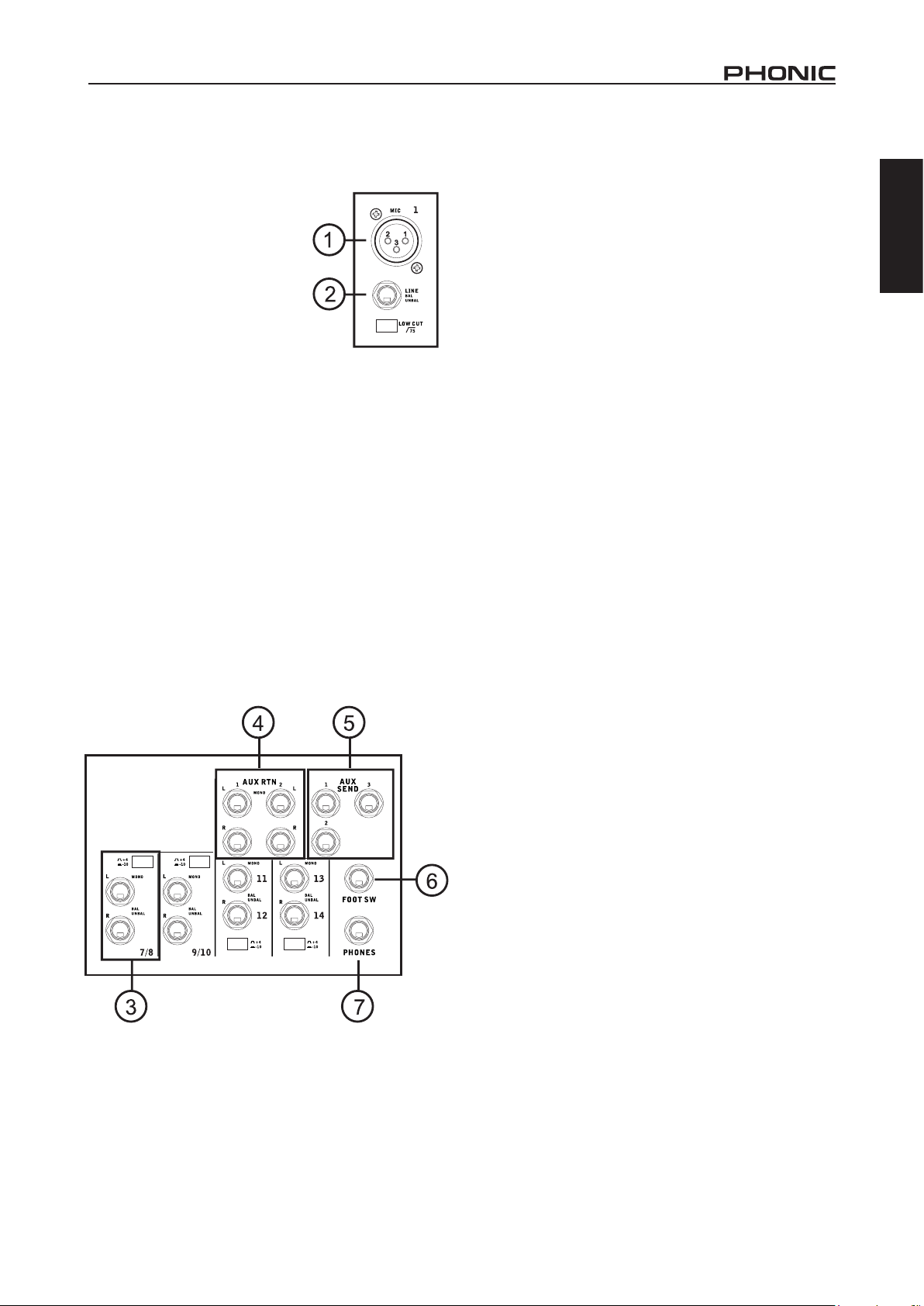
1. XLR Microphone Jacks
These jacks accept typical
3-pin XLR inputs for balanced
and unbalanced signals. They
can be used in conjunction
with microphones–such as
professional condenser,
dynamic or ribbon microphones
– with standard XLR male
connectors, and feature low
noise preampliers, serving for crystal clear sound
replication. The AM642D mixers feature a total of six
XLR microphone inputs.
NB. When these inputs are used with condenser microphones,
the Phantom Power should be activated. However, when Phantom
Power is engaged, single ended (unbalanced) microphones and
instruments should not be used on the Mic inputs.
2. Line Inputs
This input accepts typical 1/4” TRS balanced or
TS unbalanced inputs, for balanced or unbalanced
signals. They can be used in conjunction with a wide
range of line level devices such as keyboards, drum
machines, electric guitars, and a variety of other
electric instruments. These inputs are found at the rear
of the AM642D USB.
3. Stereo Channels
The AM642D mixers also feature a few stereo
channels, thrown in for maximum exibility. Each
of these stereo channels features two 1/4” phone
jacks, for the addition of various line level input
devices, such as electronic keyboards, guitars and
external signal processors or mixers. If you wish
to use a monaural device on a stereo input, simply
plug the device’s 1/4” phone jack into the left (mono)
input and leave the right input bare. The signal will
be duplicated to the right due to the miracle of jack
normalizing. The AM642D mixers feature four stereo
channels and include a +4/-10dB selector switch for
a maximum exibility.
4. AUX Returns
These 1/4” TS inputs are for the return of audio to
the AM642D mixers, processed by an external signal
processor. If really needed, they can also be used as
additional inputs. The feed from these inputs can be
adjusted using the AUX Return controls on the face
of the mixer. When connecting a monaural device to
the AUX Return 1 and 2 inputs, simply plug a 1/4”
phone jack into the left (mono) input, and the signal
will appear in the right as well. This, however, does
not work for the AUX Return 2 input on all AM642D
mixers. When the AUX Return 2 is used, the built-in
digital effects processor is automatically by-passed.
5. AUX Sends
These 1/4” TS outputs may be used to connect to
an external signal processor, or even to an amplier
and speakers (depending on your desired settings)
from the mixer. The signal from the AUX Sends is
controlled by the AUX master controls (on the face
of the mixer), which obtain their signal from the AUX
controls located on each channel strip. The AM642D
mixers feature a total of 3 AUX sends.
6. Foot Switch Jacks
This port is for the inclusion of a foot switch, used
to remotely turn the Digital Effects Processor on
and off.
English
7. Phones
This stereo output port is suited for use with
headphones, allowing monitoring of the mix. The
audio level of this output is controlled using the
Control Room / Phones control.
3AM642D / AM642DP / AM642D USB
Page 8
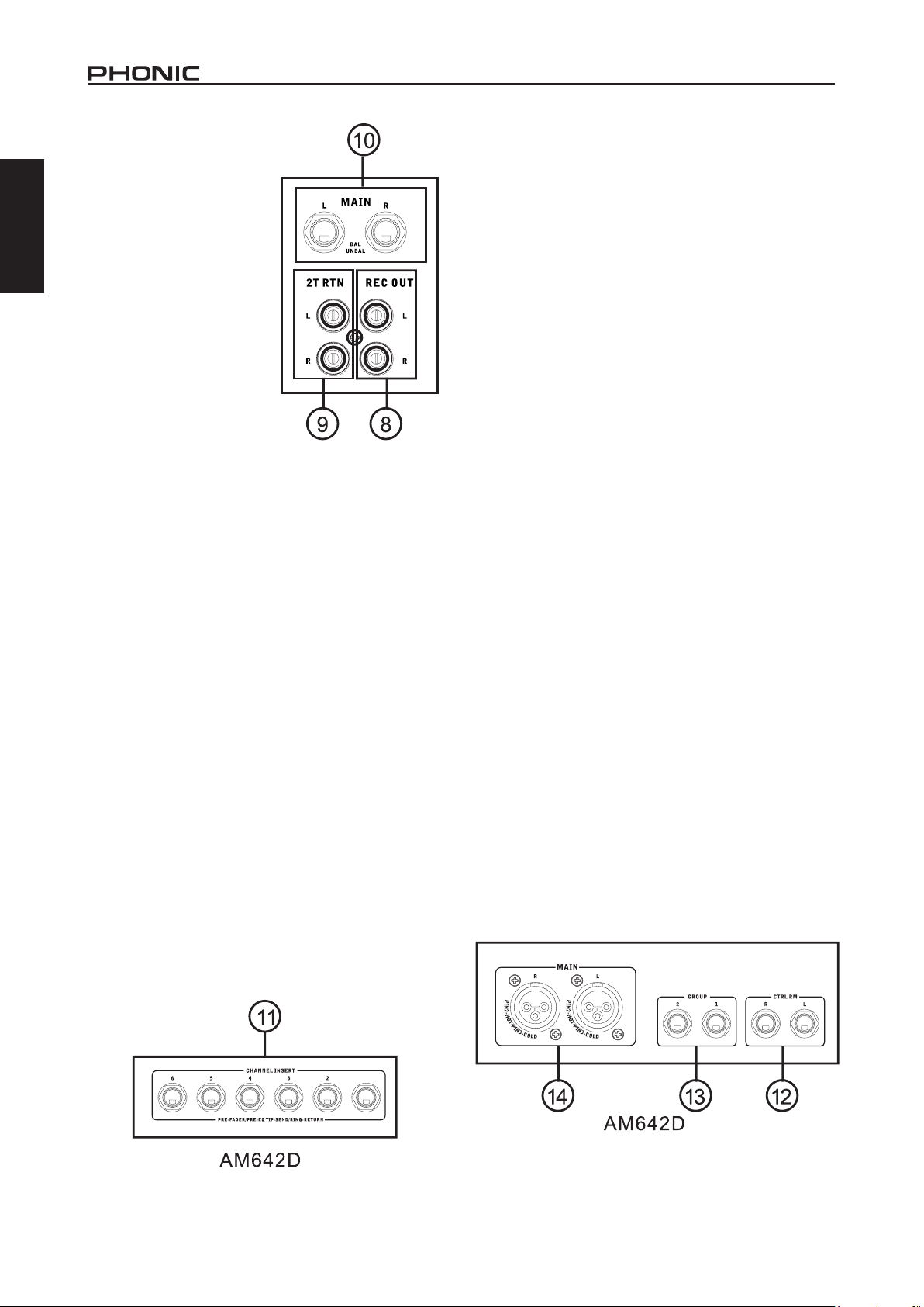
8. Record Out
These outputs will
English
accommodate RCA
cables, able to be fed
to a variety of recording
devices.
9. 2T Return
These RCA inputs are
used to connect the mixer
with external devices,
such as CD, Tape and
Cassette Players.
10. Main Out
These two XLR jacks will
output the final stereo
line level signal sent from
the main mixing bus. The
primary purpose of these jacks is to send the main
output to external devices, which may include power
ampliers (and in-turn, a pair of speakers), other
mixers, as well as a wide range of other possible
signal processors (Equalizers, Crossovers, etcetera).
Rear Panel
11. Channel Inserts
Located on the rear of the mixer, the primary use for
these TRS phone jacks is for the addition of external
devices, such as dynamic processors or equalizers,
to mono input channels 1 through 6 on the AM642D
mixers. This send and return will require a Y cord
that can send (pre-fader and pre-EQ) and receive
signals to and from an external processor.
12. Control Room Outputs
These two 1/4” phone jack outputs feed the signal
altered by the Control Room / Phones level control
on the face of the mixer. This output has extensive
use, as it can be used to feed the signal from the
mixer to an active monitor, for the monitoring of the
audio signal from within a booth, or, alternatively, for
the addition of external signal processing devices
or mixers, as well as acting as a “side ll” output,
supplying audio to indoor areas that the main
speakers do not reach.
13. Group Out
These 1/4” phone jacks output the nal feed from
the Group 1 and 2 Faders on the main mixer. These
outputs can be used to feed a wide range of devices,
such as mixers, signal processors, and even to
connect an amplier and speakers to be used along
with the Main Speakers, for a more rounded audio
experience.
14. Main Out
These two XLR ports will output the nal stereo
line level signal sent from the main mixing bus.
The primary purpose of these jacks is to send the
main output to external devices, which may include
power ampliers (and in-turn, a pair of speakers),
other mixers, as well as a wide range of other
possible signal processors (equalizers, crossovers,
etcetera).
4 AM642D / AM642DP / AM642D USB
Page 9
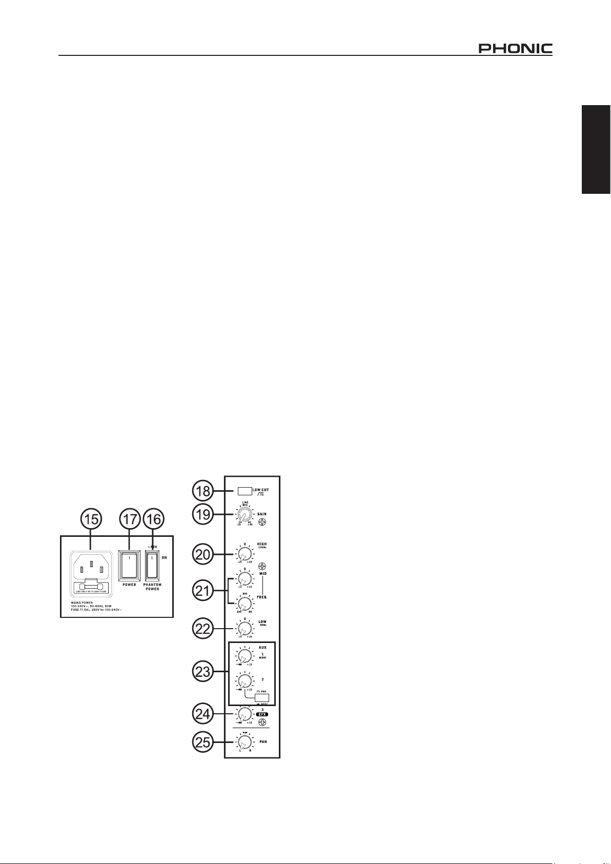
15. Power Connector
This port is for the addition of a power cable, allowing
power to be supplied to the mixer. Please use the
power cable that is included with this mixer only.
Controls and Settings
Rear Panel
Channel Controls
18. Low Cut Filter (75 Hz)
This button will activate a high-pass lter that reduces
all frequencies below 75 Hz at 18 dB per Octave,
helping to remove any unwanted ground noise or
stage rumble. This Low Cut Filter is only available
on Mic channels.
English
16. Phantom Power Switch
When this switch is in the on position, it activates
+48V of phantom power for all microphone inputs,
allowing condenser microphones (well, the ones that
don’t use batteries) to be used on these channels.
Activating Phantom Power will be accompanied by
an illuminated LED above the left channel Level
Meter. Before turning Phantom Power on, turn all
level controls to a minimum to avoid the possibility of
a ghastly popping sound from the speakers.
NB. Phantom Power should be used in conjunction
with balanced microphones. When Phantom Power
is engaged, single ended (unbalanced) microphones
and instruments should not be used on the Mic
inputs. Phantom Power will not cause damage to
most dynamic microphones. If unsure, however, the
microphone’s user manual should be consulted.
17. Power Switch
This switch is used to turn the mixer on and off.
Ensure you turn all level controls down before
activating.
19. Line/Mic Gain Control
This controls the sensitivity of the input signal of the
Line/Microphone input. The gain should be adjusted
to a level that allows the maximum use of the audio,
while still maintaining the quality of the feed. This can
be accomplished by adjusting it to a level that will
allow the peak indicator occasionally illuminate.
20. High Frequency Control
This control is used to give a shelving boost or cut of
±15 dB to high frequency (12 kHz) sounds. This will
adjust the amount of treble included in the audio of
the channel, adding strength and crispness to sounds
such as guitars, cymbals, and synthesizers.
21. Middle Frequency Control
This control is used to provide a peaking style of
boost and cut to the level of middle frequency sounds
at a range of ±15 dB. These mixers also provide
a sweep control, allowing you to select a center
frequency between 100 Hz and 8 kHz. Changing
middle frequencies of an audio feed can be rather
difcult when used in a professional audio mix, as
it is usually more desirable to cut middle frequency
sounds rather than boost them, soothing overly harsh
vocal and instrument sounds in the audio.
The stereo channels feature High-Mid and Low-Mid
controls instead of the typical controls described
above. They provide a peaking style of boost and cut
to middle frequencies, where the frequencies are set
at 3 kHz and 800 Hz, respectively.
22. Low Frequency Control
This control is used to give a shelving boost or cut
of ±15 dB to low frequency (80 Hz) sounds. This will
adjust the amount of bass included in the audio of
the channel, and bring more warmth and punch to
drums and bass guitars.
23. AUX Control
This control alters the signal level that is being sent
to the auxiliary 1 mixing bus, the signal of which
is suitable for connecting stage monitors, allowing
artists to listen to the music that is being played.
Also included is a Pre/Post button which alternates
the feed to the AUX mixing bus between a post and
pre-fader feed.
5AM642D / AM642DP / AM642D USB
Page 10
24. EFX Control
This control alters the signal level that is sent to the
English
EFX send (AUX 3) output and the built-in digital
effect processor. The EFX send signal can be used
in conjunction with external signal processors (this
signal of which can be returned to mixer via the AUX
return input), or simply as an additional auxiliary
output.
25. Pan / Balance Controls
This alternates the degree or level of audio that the
left and right side of the main mix should receive. On
Mic channels, the PAN control will adjust the level
that the left and right should receive (pan), where as
on a stereo channel, adjusting the BAL control will
attenuate the left or right audio signals accordingly
(balance).
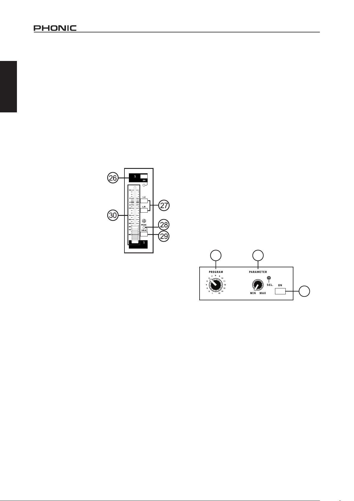
26. On Button and
Indicator
This turns the channel
on, allowing the user to
use the feed from the
channel’s inputs to supply
the MAIN L/R, GROUP 1/2,
AUX and EFX buses. The
corresponding indicator
will be illuminated when
turned on.
27. 1-2 and L/R Buttons
These handy buttons allow you to decide the audio
path of the corresponding channel. Pushing the “12” button allows the signal to be sent to the Group
1-2 mix, where the “L/R” allows it to be sent to the
Main L/R mix.
30. Level Faders
These faders allow users to adjust the level of the
signal from the corresponding input channel that is
to be sent to the destinations selected by the 1-2
and L/R buttons.
Digital Effect Processor
31. Program Control
This rotary control allows users to select the digital
effect program of your choice. There are 16 points
on the rotary control, each of which corresponds with
an effect type. See the digital effect table for more
information.
32. Parameter Control
Turning this control will adjust the one main parameter
of the selected effect. Each effect’s parameter can
be found on the digital effect table.
33. Effect On Button
This button is pushed to turn the corresponding effect
panel on or off. Effects can also be disabled by using
a footswitch with the jack on the rear of the mixer.
Please note: this button will not lock down as similar
buttons on the mixer do.
31 32
33
28. Peak Indicator
This LED indicator will illuminate when the channel
hits high peaks, 6 dB before overload occurs. It is
best to adjust the channel level control to a level
slightly prior to the peak indicator does not light up.
This will ensure a greater dynamic range of audio.
This indicator also doubles as a Solo indicator, when
the SOLO button is engaged.
29. Solo Button
The Solo button is pushed to allow the signal of a
corresponding channel to be sent to the Control
Room / Phones control. The signal is either that of a
pre- or post-fader depending on the pre/post button
in the master section.
6 AM642D / AM642DP / AM642D USB
Master Section
34. AUX Return Controls
These controls adjust the signal level of audio fed
through to the stereo AUX Return inputs. The “To AUX
1” control adjusts the pre-fader level of the signal from
the AUX Return inputs to the AUX 1 mixing buses.
35. EFX Return (AUX Return 2) Control
This control adjusts the signal level of audio fed
through to stereo AUX Return 2 inputs. If no device
is plugged into the AUX Return 2 inputs, this control
then acts as the nal level control of the built-in Digital
Effect Engine.
Page 11
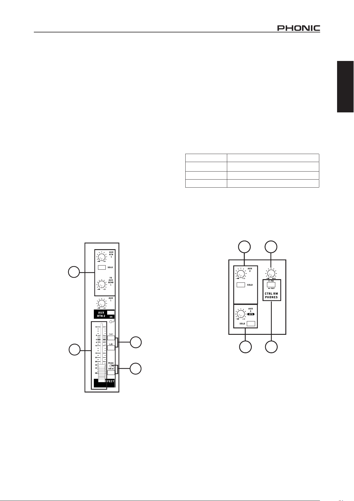
36. Main L/R and Group 1-2 Buttons
The EFX Return control is accompanied by Main L/
Rand Group 1-2 buttons. These buttons change the
destination of the EFX Return signal between the
Main L/R signal and/or Group 1-2 sub mix.
37. Return Solo Buttons
Pushing either of the Return Solo buttons allows
users to send the signal from the AUX Returns 1
and/or 2 to the Control Room / Phones mixing bus.
38. AUX Send Master Control
This control adjusts the nal level of the AUX mixing
bus (as taken from the AUX level controls on each
channel strip), the audio of which is sent to AUX Send
output. The corresponding SOLO button allows you
to send the AUX Send signal to the Control Room /
Phones mixing bus. The AM642D mixers feature 3
sends, where the rst is in fact a 60mm fader, rather
than the simple rotary control. Also incorporated with
the AUX 1 control of the AM642D mixers is a Peak
LED, as well as an ON button and indicator, allowing
AUX 1 to be activated and muted when required.
Activation of AUX Send 1 is, of course, accompanied
by an illuminated LED.
39. EFX Send Master Control
This control adjusts the nal level of the EFX mixing
bus (as taken from the EFX level controls on each
channel strip), the audio of which is sent to the AUX
Send 3 outputs, as well as the built-in digital effect
engine. The corresponding SOLO button allows you
to send the signal to the Control Room / Phones
mixing bus.
40. Control Room / Phones Controls
This control is used to adjust the audio level of the
Phones feed, as well as the signal sent to the Control
Room output, for use in monitoring and tracking of
audio.
Priority Signal
Highest From Solo
Medium 2T Return to Control Room
Lowest Main L/R
41. Pre / Post Control
This button alternates the Control Room / Phones
source signals between those of post-fader and
pre-fader feeds.
English
34
35
38 40
36
4139
37
7AM642D / AM642DP / AM642D USB
Page 12

42. 2T Return Controls
Turning the 2T Return level control adjusts the signal
English
level of the feed from the 2T Return inputs, the signal
of which is sent to the Main L/R mixing bus. Pushing
the “to Ctrl Rm” button sends the signal to the Control
Room/Phones mixing bus also. These also double
as the input controls for the USB interface on the
AM642D USB.
43
44
45
42
43. +48V Indicator
This indicator will illuminate when Phantom Power
is activated.
44. Power Indicator
The Power Indicator will light up when the power of
the mixer is on; in case you weren’t too sure.
45. Level Meter
This dual 12-segment level meter gives an accurate
indication of when audio levels of the Main L/R output
reach certain levels. The 0 dB indicator illuminates
is approximately equal to an output level of +4 dBu
(balanced), and the PEAK indicator illuminates
slightly before the signal is dynamically clipped. It is
suggested that users set the various levels controls
so that the level meter sits steadily around the 0
dB mark to make full use of the audio while still
maintaining fantastic clarity.
When the Solo indicator (located beside the Level
Meter) is illuminated, one or more Solo buttons
has been pushed and the Level meter will display
properties of the Solo signal, which can be helpful
with setting of channel properties. If Solo indicator
illuminates green, this means the Solo feed is a prefader signal. If the solo indicator illuminates red, the
feed is post-fader. If the no Solo buttons are activated,
the 2T Return signal properties are displayed by the
Level Meter, unless the "To Ctrl Rm" button is not
pressed, in which case the Main L-R signal properties
will be displayed.
46. Group Controls
These two faders are the nal level control for the
Group 1 and 2 audio feeds, sent to the Group 1 and
2 outputs. These faders can be fed a signal from the
various mono and stereo channels, as well as EFX
Returns, depending on your selections. When pushed
all the way up, these faders provide 10 dB of gain to
the signal, and, when set all the way down, effectively
mute the signal. The Group Controls also feature Left
and Right buttons, which allow you to send the Group
1-2 signals to the Main Left and Right mixing buses.
47. Main L/R Faders
These two faders are the nal level control for the
Main Left and Right audio feeds, sent to the Main L
and R outputs. These faders are possibly fed by the
various mono and stereo channels, as well as AUX
and EFX returns and 2T inputs, depending on the
your selections. When pushed all the way up, these
faders provide 10 dB of gain to the signal, and, when
set all the way down, effectively mute the signal.
Priority Signal
Highest From Solo
Medium 2T Return to Control Room
Lowest Main L/R
8 AM642D / AM642DP / AM642D USB
46 47
Page 13

48. Graphic Equalizer
This stereo 9 band graphic equalizer allows the user
to adjust the frequency response of a signal, with a
maximum of ±12 dB of signal boost or cut for each of
the frequencies. The AUX 1 / MAIN switch alternates
the use of the equalizer between the use of the AUX 1
bus and MAIN L/R bus signals. Pushing the on button
in activates the equalizer, which is accompanied by
an illuminated LED.
48
USB Player (AM642DP)
When playing back a signal, the signal will pass through
the USB In control and then is sent directly to the main
mix. Playback of WAV, WMA and MP3 with bit rates of up
to 320 kbit/s is possible.
49. Display
This display will display the track number currently being
played. It also offers play, pause indicators as well as the
current play time.
51. Play Button
Push this button to start playback of the currently displayed
track. Starting a track after it is paused will resume the track
from the point at which it was paused.
52. Back/Next Buttons
Pushing these buttons will allow users to skip back and
forwards between tracks in sequence. When the menu
is activated, these buttons are used to scroll through on
screen options.
53. Stop/Menu Button
Push this button to stop playback. Push and hold the button
to access the USB player’s main menu.
AM642D USB
54. USB Port
This USB connector can be used to connect the AM642D
USB to any modern Windows or Mac-based computer.
Doing so will allow users to get a stereo signal both to
and from the computer. The signal received through this
interface will be sent to the 2T Return bus.
54
English
50. USB Port
Connect your USB ash drive to this input. Once a drive is
connected, the les will initiate and the rst track will appear
paused on screen. Users are advised to format their USB
memory sticks with the FAT-32 le system.
50
49
51
55. Compressor Control and Indicator
This controls the onboard compressor function on mono
channels. Turning this control up towards the 12 o’clock
position will adjust the threshold and ratio of the compressor
at varying degrees. Once you reach the 12 o’clock position,
the control will then adjust the compression settings along
with an onboard expander (or, in other words, a compander).
The LED that accompanies this control will light up when
the compressor is triggered.
55
52 53
9AM642D / AM642DP / AM642D USB
Page 14
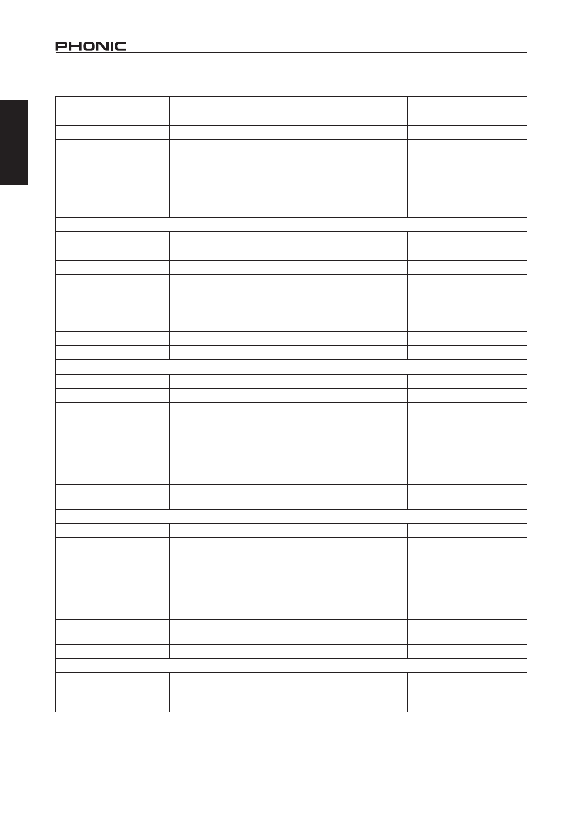
SPECIFICATIONS
English
Inputs
Total Channels 10 10 10
Balanced Mono Mic / Line
channel
Balanced Stereo Line
Channel
Aux Return 2 stereo 2 stereo 2 stereo
2T Input Stereo RCA Stereo RCA Stereo RCA
Outputs
Main L/R Stereo 2 x 1/4” TRS, Bal. & 2 x XLR 2 x 1/4” TRS, Bal. & 2 x XLR 2 x 1/4” TRS, Bal. & 2 x XLR
Rec Out Stereo RCA Stereo RCA Stereo RCA
CTRL RM L/R 2 x 1/4” TS 2 x 1/4” TS 2 x 1/4” TS
Phones 1 1 1
Channel Strips 10 10 10
Aux Sends 3 3 3
Pan/Balance Control Yes Yes Yes
Channel insert CH 1~ CH 6 CH 1~ CH 6 CH 1~ CH 6
Volume Controls 60mm fader 60mm fader 60mm fader
Master Section
Aux Send Masters 3 3 3
Master Aux Send Solo 3 3 3
Stereo Aux Returns 2 2 2
Aux Return Assign to
Subgroup
Effects Return to Monitor 2 2 2
Global AFL/PFL Solo Mode Yes Yes Yes
Phones Level Control Yes Yes Yes
Faders
Metering
Number of Channels 2 2 2
Segments 12 12 12
Phantom Power Supply +48V DC +48V DC +48V DC
Switches Master Master Master
32/40-bit Digital Effect
Processor
Built-in Graphic EQ Stereo 9-band Stereo 9-band Stereo 9-band
Center Frequency
Range ±12 dB ±12 dB ±12 dB
USB Player
Maximum Playback Bitrate - 320 kbit/second Supported Playback
Formats
AM642D AM642DP AM642D USB
6 6 6
4 4 4
1 1 1
Aux return 2, Aux 1, 2
subgroups, Main L & R
16 effects 16 effects 16 effects
60, 160, 315, 630, 1.25K,
2.5K, 5K, 10K, 16K Hz
- WAV, WMA and MP3 -
Aux return 2, Aux 1, 2
subgroups, Main L & R
60, 160, 315, 630, 1.25K,
2.5K, 5K, 10K, 16K Hz
Aux return 2, Aux 1, 2
subgroups, Main L & R
60, 160, 315, 630, 1.25K,
2.5K, 5K, 10K, 16K Hz
10 AM642D / AM642DP / AM642D USB
Page 15

AM642D AM642DP AM642D USB
USB Interface - - Stereo In/Out
Connector Type - - USB Type B
Bitrate - - 16-bit
Frequency Response (Mic input to any output)
20Hz ~ 60KHz +0/-1 dB +0/-1 dB +0/-1 dB
20Hz ~ 100KHz +0/-3 dB +0/-3 dB +0/-3 dB
Crosstalk (1KHz @ 0dBu, 20Hz to 20KHz bandwidth, channel in to main L/R outputs)
Channel fader down, other
channels at unity
Noise (20Hz~20KHz; measured at main output, Channels 1-4 unit gain; EQ at; all channels on main mix; channels 1/3
as far left as possible, channels 2/4 as far right as possible. Reference=+6dBu)
Master @ unity, channel
fader down
Master @ unity, channel
fader @ unity
S/N ratio, ref to +4 >90 dB >90 dB >90 dB
Microphone Preamp E.I.N.
(150 ohms terminated, max
gain)
THD (Any output, 1KHz @
+14dBu, 20Hz to 20KHz,
channel inputs)
CMRR (1 KHz @ -60dBu,
Gain at maximum)
Maximum Level
Mic Preamp Input +10dBu +10dBu +10dBu
All Other Input +21dBu +21dBu +21dBu
Balanced Output +28dBu +28dBu +28dBu
Impedance
Mic Preamp Input 2 K ohms 2 K ohms 2 K ohms
All Other Input (except
insert)
RCA 2T Output 1.1 K ohms 1.1 K ohms 1.1 K ohms
Ch Equalization
Low EQ 80Hz 80Hz 80Hz
Mid EQ (mono channel) 100-8k Hz, sweepable 100-8k Hz, sweepable 100-8k Hz, sweepable
LMid EQ (stereo channel) 800 Hz 800 Hz 800 Hz
HMid EQ (stereo channel) 3 kHz 3 kHz 3 kHz
Hi EQ 12 kHz 12 kHz 12 kHz
Low cut lter 75 Hz (-18 dB/oct) 75 Hz (-18 dB/oct) 75 Hz (-18 dB/oct)
Built-in Power Supply 100-240 VAC, 50/60 Hz 100-240 VAC, 50/60 Hz 100-240 VAC, 50/60 Hz
Weight 10.6 lbs (4.8 kg) 10.6 lbs (4.8 kg) 10.6 lbs (4.8 kg)
Dimensions (WxHxD)
<-90 dB <-90 dB <-90 dB
-86.5 dBu -86.5 dBu -86.5 dBu
-84 dBu -84 dBu -84 dBu
<-129.5 dBm <-129.5 dBm <-129.5 dBm
<0.005% <0.005% <0.005%
80dB 80dB 80dB
10 K ohms 10 K ohms 10 K ohms
3-band, +/-15dB
(4-band on Stereo Ch)
16” x 3.5” x 14”
(407 x 89 x 357 mm)
3-band, +/-15dB
(4-band on Stereo Ch)
16” x 3.5” x 14”
(407 x 89 x 357 mm)
3-band, +/-15dB
(4-band on Stereo Ch)
16” x 3.5” x 14”
(407 x 89 x 357 mm)
English
11AM642D / AM642DP / AM642D USB
Page 16

English
SERVICE AND REPAIR
For replacement parts, service and repairs please contact the Phonic distributor in your
country. Phonic does not release service manuals to consumers, and advice users to not
attempt any self repairs, as doing so voids all warranties. You can locate a dealer near you at
http://www.phonic.com/where/.
WARRANTY INFORMATION
Phonic stands behind every product we make with a no-hassles warranty. Warranty coverage
may be extended, depending on your region. Phonic Corporation warrants this product for a
minimum of one year from the original date of purchase against defects in material and
workmanship under use as instructed by the user’s manual. Phonic, at its option, shall repair
or replace the defective unit covered by this warranty. Please retain the dated sales receipt as
evidence of the date of purchase. You will need it for any warranty service. No returns or repairs
will be accepted without a proper RMA number (return merchandise authorization). In order to
keep this warranty in effect, the product must have been handled and used as prescribed in the
instructions accompanying this warranty. Any tampering of the product or attempts of self repair
voids all warranty. This warranty does not cover any damage due to accident, misuse, abuse,
or negligence. This warranty is valid only if the product was purchased new from an authorized
Phonic dealer/distributor. For complete warranty policy information, please visit
http://www.phonic.com/warranty/.
CUSTOMER SERVICE AND TECHNICAL SUPPORT
We encourage you to visit our online help at http://www.phonic.com/support/. There you can find
answers to frequently asked questions, tech tips, driver downloads, returns instruction and other
helpful information. We make every effort to answer your questions within one business day.
support@phonic.com
http://www.phonic.com
12 AM642D / AM642DP / AM642D USB
Page 17

MANUAL DEL USUARIO
CONTENTS
INTRODUCCIÓN..............................................................1
CARACTERÍSTICAS....................................................1
AM642D USB CONECCIONES DE LA COMPUTADORA......1
COMENZANDO.........................................................2
CONFIGURACIÓN DE CANAL.......................................2
HACIENDO CONEXIONES...........................................3
Entradas y Salidas............................................................3
Panel de Dorso..............................................................4
CONTROLES Y CONFIGURACIONES.....................................5
Panel de Dorso......................................................5
Controles de Canal.....................................................5
English Español
Procesador de Efecto Digital......................................6
Sección Maestro................................................................7
Reproductor USB...................................................9
AM642D USB.....................................................................9
ESPECIFICACIONES...................................................10
APPENDIX
DIMENSIONES.................................................................1
TABLA DE EFECTO DIGITAL............................................1
APLICACIÓN...............................................................2
DIAGRAMAS DE BLOQUE..................................................3
Phonic se reserva el derecho de mejorar o alterar cualquier información
provista dentro de este documento sin previo aviso
Page 18

English Español
Page 19

INTRODUCCIÓN
Gracias por elegir una de las muchas mezcladoras
compactas de calidad de Phonic. Las nuevas Mezcladoras
AM642D, AM642DP y AM642D USB – diseñadas por
ingenieros brillantes que han creado una variedad de
fantásticas mezcladoras en estilo y funcionamiento en el
pasado – lucen capacidad similar que han demostrado
los productos de Phonic anteriormente, con un poco
más de renamiento por supuesto. Presentando
rango de ganancia completo, niveles de distorsión
sorprendentemente bajos e increíbles rangos dinámicos
amplios, estas mezcladoras asombrosas seguramente
harán un gran impacto en el mundo de la mezcla.
Sabemos que está ansioso de comenzar – queriendo
sacar la mezcladora e instalar todo es probablemente su
primer prioridad en este momento- pero antes de hacerlo,
le sugerimos encarecidamente que eche un vistazo a
este manual. En su contenido, usted encontrará hechos
importantes e ilustraciones sobre conguración, uso y
aplicaciones de su nueva mezcladora. Si usted es una
de esas personas que se rehusa rotundamente a leer los
manuales de usuario, entonces solo le pedimos que por
lo menos hojea las primeras páginas. Luego de hojear
o leer el manual (le aplaudimos si usted leyó el manual
entero), por favor guardelo en un lugar de fácil acceso ya
que puede haberle escapado algo en la primera leída.
CARACTERÍSTICAS
6 canales de Mic/Línea con inserts y fuente fantasma
Calidad audiólo & ruido ultra bajo
4 canales de estéreo con EQ de 4 bandas
EQ de 3 bandas con barrido de rango medio más
corte bajo en cada canal mono
Procesador de efectos estéreo digital de 32/40-bit
con 16 programas
3 envíos Aux, uno con interruptor Pre/Post
EQ gráco estéreo de 9 bandas, asignable a mezcla
principal o envío aux 1
2 subgrupos anados con interruptores de ruteo
principal I y D
2 retornos aux estéreo con efecto a control de nivel
de monitor
Característica de Solo en cada entrada y salida
Conectores XLR disponibles en salida principal I/D
Fuente de alimentación intercambiable integrada con
conector universal, 100-240VAC, 50/60Hz
Kit de montaje en rack incluido
AM642DP también presenta:
Reproducción USB estéreo desde cualquier USB
ash driver estánda
AM642D USB también presenta:
Compresor ajustable en canales mono
Interfaz USB estéreo audio para computadoras PC y
Mac
AM642D USB CONECCIONES DE
LA COMPUTADORA
Simplemente conecte el cable de USB que le ofrecemos
con su AM642D USB a su computadora personal o por-tátil,
usted podrá enviar señales de calidad CD (16-bit estéreo
con 44.1 KHz frecuencia de muestreo) a su mezcladora.
En ejecutar este proceso usted está convirtiendo su
AM642D USB en una tarjeta de sonido altamente eciente
para conectar y usar desde su computadora.
El USB envía un ujo de audio señal al Central izquierdo y
derecho (record out) de su mezcladora a la computadora.
Usted puede emplear cualquier programa de Didigtal
Audio Workstation (DAW) para grabar la señal desde su
mezcladora AM. Usted también congurarlo la unidad con
audios predeterminados. El interfase USB también retorna
las señales audio desde su computadora al 2T Retorno,
señal que es controlada por 2T/USB control retorno. Si
hay señales de entrada provenientes de ambos interfases
USB y 2T Retorno, las dos señales son combinadas y
contraladas simultáneamente por el control de 2T retorno.
Windows
1. Encienda su mezcladora AM y computadora.
2. Conecte la mezcladora AM a al computadora por
medio del cable USB que le ofrecemos.
3. Espere que Windows localice la unidad e instale el
driver apropiado.
4. Entre al Panel de Control y seleccione los dispositivos
de Sonido y Audio.
5. En esta etapa elija el Audio tab y seleccione el
“USB Audio Codec” como su sonido de grabación
predeterminado y dispositivo de reproducción.
6. Dependiendo si usted usa Windows XP, Vista, 7 o
8, habrá diferencias pero la conguración siempre
se podrá encontrar en el menú del Panel de Control
Audio.
7. Si usted no desea usar su AM como el dispositivo
predeter-minado de audio, simplemente entre en
su DAW u otro pro-grama de audio y seleccione
su dispositivo predeterminado en el programa
solamente.
8. Asegúrese de que la conguración minima de su
buffer este jada en 64 muestreos (samples) para
evitar clicks y pops.
Mac
1. Encienda el su mezcladora AM642D USB y la
computadora.
2. Conecte la mezcladora AM a la computadora por
medio del cable USB que le ofrecemos.
3. Entre al menú AUDIO MIDI SETUP.
4. Seleccione el “USB Audio Codec” como su dispositivo
de entrada y salida.
5. Ahora el AM642D USB es ahora su dispositivo audio
predeterminado.
English Español
AM642D / AM642DP / AM642D USB
1
Page 20

6. Alternativamente, entre a su programa de DAW (u
otro programa de audio) y seleccione “USB Audio
English Español
Codec” en el dispositivo de preferencia.
7. Asegúrese de que la conguración minima de su
buffer este jada en 64 muestreos (samples) para
evitar clicks y pops.
Requisitos Del Sistema (AM642D USB)
Windows
Windows™ XP SP2, Vista™, 7 o 8
Procesador Intel™ Pentium™ 4 o más alta
512 MB RAM (1 GB recomendado)
Macintosh
Apple™ Mac™ OSX 10.5 o más alta
Procesador G4™ o mejor
512 MB RAM (1 GB recomendado)
COMENZANDO
1. Asegúrese que todas las energías en su mezcladora
estén apagadas. Para estar completamente seguro
de ésto, el suministro de energía no debería estar
conectado a la unidad.
2. Todos los faders y controles de nivel deberían estar
seteados en el nivel más bajo y todos los canales
apagados para asegurar que el sonido no se envíe
inadvertidamente a las salidas cuando se enciende el
dispositivo. Todos los niveles pueden ser alterados a
grados aceptables una vez encendido el dispositivo.
3. Enchufe todos los instrumentos y equipos necesarios
en las varias entradas de dispositivo. Estos podrían
incluir dispositivos de señal de línea, tales como
teclados, máquinas de batería, micrófonos y/o
guitarras, etc.
4. Enchufe todos los equipos necesarios en las
varias salidas de dispositivo. Estos podrían incluir
amplicadores, altavoces, monitores, procesadores
de señal y/o dispositivos de grabación.
5. Enchufe el cable AC suminitrado en la entrada AC
de la parte dorsal del dispositivo y a una salida de
energía de un voltaje compatible.
6. Encienda el interruptor de energía.
CONFIGURACIÓN DE CANAL
1. Para asegurar el nivel de audio de canal de entrada
es correcto, los botones de ENCENDIDO(ON)
de cada canal de la mezcladora deberían de estar
desenganchados (que debería apagar el indicador
LED correspondiente –de otra manera retroceda y
pruebe de nuevo), también los botones SOLO de
cada canal, y asegúrese que la perilla 2T RTN está
todo hacia abajo.
2. Asegúrese de que el canal que desea congurar
tenga una señal de envío similar a la señal que será
enviada en uso común. Por ejemplo, si el canal tiene
un micrófono conectado, entonces debería hablar o
cantar al mismo nivel que el cantante usaría durante
su presentación. Si se conecta una guitarra en ese
canal, entonces la guitarra también debería ser
tocada como es normalmente (y así sucesivamente).
Esto asegura que los niveles sean completamente
precisos y evita tener que resetearlos luego.
3. Mueva el fader de Canal y los faders Principal I D
alrededor de 0 dB.
4. Encienda el Canal.
5. Al pulsar el botón SOLO de canal y liberar el botón
Pre/Post en la sección CTRL RM enviará la señal prefader de canal activado a bus de mezcla de Control
Room / Phones y el Medidor de Nivel mostrará las
propiedades de la señal de Control Room.
6. Ajuste la ganancia para que el medidor de nivel
indique el nivel de audio alrededor de 0 dB.
7. Este canal está ahora listo para usarse; usted puede
dejar de hacer la prueba de audio.
8. Puede repetir el mismo proceso para otros canales si
lo desea.
2
AM642D / AM642DP / AM642D USB
Page 21

HACIENDO CONEXIONES
Entradas y Salidas
1. Jacks XLR de Micrófono
Estos jacks aceptan entradas
típicas XLR de 3 pines
para señales simétricos y
asimétricos. Pueden ser
utilizados junto con micrófonos
– tales como de condensador
profesional, dinámicos o
de cinta – con conectores
machos XLR estándares y
preamplicadores de bajo
ruido, sirven para reproducción de audio limpio cristalino.
La mezcladora AM 642D presenta seis entradas de
micrófono estándares XLR.
Nota: Cuando se utilizan estas entradas con micrófonos de
condensador, la Fuente Fantasma deberá ser activada. Sin
embargo, cuando se emplea la Fuente Fantasma, los micrófonos
de simple terminación (desbalanceados) e instrumentos no
deberían ser utilizados en las entradas Mic.
2. Entradas de Línea
Estas entradas aceptan entradas típicas de 1/4” TRS
balanceadas o TS desbalanceadas, para señales
balanceadas y desbalanceadas. Pueden ser utilizadas
junto con un rango amplio de dispositivos de nivel de línea
como teclados, máquinas de batería, guitarras eléctricas
y una variedad de otros instrumentos eléctricos. Estas
entradas se encuentran en la parte trasera de la AM642D
USB .
3. Canales de Estéreo
Las mezcladoras AM 642D también presentan pocos
canales de estéreo, añadiendo máxima exibilidad. Cada
uno de estos canales de estéreo presenta dos jacks
auricular de 6.35mm, para adición de varios dispositivos
de entrada de nivel de línea, tales como teclados
electrónicos, guitarras y procesadores de señal externos
o mezcladoras. Si desea usar un dispositivo monoaural
en una entrada de estéreo, simplemente enchufe el
jack audífono de 6.35mm en en la entrada izquierda
(mono) y deje la entrada derecha desenchufado. La
señal se duplicará a la derecha, debido al milagro de
la normalización de jack. El AM 642D presentan cuatro
canales estéreo e incluye un interruptor de selector +4/-
10dB para una máxima exibilidad.
4. Retornos AUX
Estas entradas de TS de 6.35mm son para el retorno
de audio a las mezcladoras AM 642D, procesado por un
procesador de señal externo. Si realmente se necesita,
pueden ser utilizadas también como entradas adicionales.
La alimentación de estas entradas puede ser ajustada por
los controles de Retorno AUX en el panel frontal de la
mezcladora. Cuando se conecta un dispositivo monoaural
a las entradas Retorno AUX 1 y 2, simplemente enchufe
un jack audífono de 6.35mm en la entrada izquierda
(mono), y la señal aparecerá en la derecha también.
Ésto, sin embargo, no funciona para entrada de Retorno
AUX 2 en la AM642D. Cuando se usa Retorno AUX 2,
el procesador de efectos digitales integrado bypass
desviado automáticamente.
5. Envíos AUX
Estas salidas de TS de 6.35mm pueden ser usadas
para conectar a un procesador de señal externo o
a un amplicador y altavoces (dependiendo de sus
conguraciones deseadas), de la mezcladora. La señal
de Envíos AUX es controlada por los controles principales
AUX (en el panel frontal de la mezcladora), que obtienen
su señal de los controles AUX localizados en cada tira de
canal. La AM 642D presenta 3 envíos AUX,
6. Jacks de Interruptor de Pedal
Este puerto es para la inclusión de un interruptor de
pedal, utilizado para encender y apagar remotamente el
Procesador de Efectos Digitales.
7. Audífonos
Este puerto de salida estéreo es para utilizarse con
auriculares, permitiendo monitorear la mezcla. El nivel de
audio de esta salida es controlado usando el control de
Control Room / Audífonos.
English Español
AM642D / AM642DP / AM642D USB
3
Page 22

8. Salida de Grabación
Estas salidas acomodarán a los cables RCA para alimentar
English Español
a una variedad de dispositivos de grabación.
9. Retorno 2T
Estas entradas RCA son usadas para conectar la
mezcladora con dispositivos externos, tales como
reproductores de CD, Tape y Cassette.
10. Salida Principal
Estos dos jacks XLR generarán la señal nal estéreo de
nivel de línea enviada desde bus de mezcla principal.
El propósito primario de estos jacks es el de enviar la
salida principal a dispositivos externos, que pueden ser
amplicadores de potencia (alternadamente, un par de
altavoces), otras mezcladoras y también un rango amplio
de otros procesadores de señal posibles (Ecualizadores,
Crossovers, etc.).
12. Salidas de Control Room (Sala de Control)
Estas dos salidas de Jack Audífono 1/4” alimenta la señal
alterada por el control de nivel Control Room/Phones
(Sala de Control/Audífonos) en el panel frontal de la
mezcladora. Esta salida tiene uso extensivo, como puede
ser usada para alimentar la señal desde la mezcladora a
un monitor activo, para el monitoreo de la señal de audio
desde una cabina, o alternativamente, para la adición
de dispositivos de procesamiento de señal externa o
mezcladoras, también actuando como una salida de
“relleno lateral”, suministrando audio a áreas internas que
los altavoces principales no llegan.
13. Salida de Grupo
Estos jacks audífono 1/4” generan la alimentación nal
desde Faders de Grupo 1 y 2 en la mezcladora principal.
Estas salidas pueden ser usadas para alimentar un rango
amplio de dispositivos como mezcladoras, procesadores
de señal y hasta conectar un amplicador y altavoces
para ser usado junto con Altavoces Principales, para una
experiencia de audio más completa.
14. Salida Principal
Estos dos puertos XLR generarán la señal nal estéreo
de nivel de línea enviada desde bus de mezcla principal.
El propósito primario de estos jacks es el de enviar la
salida principal a dispositivos externos, que pueden ser
amplicadores de potencia (alternadamente, un par de
altavoces), otras mezcladoras y también un rango amplio
de otros procesadores de señal posibles (ecualizadores,
crossovers, etc.).
Panel de Dorso
11. Inserts de Canal
Localizados en el dorso de la AM 642D, el uso primario
para estos jacks audífono TRS es para agregar dispositivos
externos, como procesadores dinámicos o ecualizadores, a
canales de entrada mono 1 a 6 en AM 642D. Este envío y
retorno requerirá un cable Y que puede enviar (pre-fader y
pre-EQ) y recibir señales a y desde un procesador externo.
4
AM642D / AM642DP / AM642D USB
Page 23

15. Conector de Energía
Este puerto es para la adición de cable de energía,
permitiendo que la energía sea suministrada a la
mezcladora. Por favor utilice únicamente el cable de
energía que está incluido con esta mezcladora.
CONTROLES Y CONFIGURACIONES
Panel de Dorso
16. Interruptor de Fuente Fantasma
Cuando este interruptor está en la posición de encendido,
se activa +48V de fuente fantasma para todas las
entradas de micrófono, permitiendo que los micrófonos
de condensador (bueno, los que no utilizan baterías)
sean usados en estos canales. La activación de Fuente
Fantasma será acompañada por un LED iluminado sobre
el canal izquierdo de Medidor de Nivel. Antes de encender
la Fuente Fantasma, regule todos los controles de nivel
a mínimo para evitar la posibilidad de un sonido súbito
horroroso saliendo de los altavoces.
Nota: La Fuente Fantasma debería ser utilizada junto con los
micrófonos balanceados. Cuando se emplea la Fuente Fantasma,
los micrófonos de simple terminación (desbalanceados) e
instrumentos no deberían ser utilizados en entradas Mic. La
Fuente Fantasma no causará daño a la mayoría de los micrófonos
dinámicos. Sin embargo, si está inseguro debería consultar el
manual del usuario.
17. Interruptor de Energía
Este interruptor es usado para encender o apagar la
mezcladora. Asegúrese de bajar todos los controles de
nivel antes de la activación.
Controles de Canal
18. Filtro de Corte Bajo (75Hz)
Este botón activará un ltro de paso-alto que reduce
todas las frecuencias debajo de 75Hz en 18dB por
Octava, ayudando a eliminar cualquier ruido ambiental o
de escenario no deseado. Este Filtro de Corte Bajo está
disponible solamente en los canales Mic en la AM642D.
19. Control de Ganancia de Línea/Mic
Controla la sensibilidad de la señal de entrada de Línea/
Micrófono. La ganancia debería ser ajustada a un nivel
que permita el uso máximo de audio, mientras siga
manteniendo la calidad de la alimentación. Ésto puede
ser logrado ajustandolo a un nivel que permite que el
indicador de pico se ilumine ocasionalmente.
20. Control de Frecuencia Alta
Este control es usado para dar un aumento o recorte de
±15 dB a los sonidos de frecuencia alta (12 kHz). Ajustará
la cantidad de agudo incluido en el audio del canal,
agregando fuerza y claridad a sonidos como guitarras,
címbalos y sintetizadores.
21. Control de Frecuencia Media
Este control es usado para proveer un estilo de pico de
aumento o recorte a nivel de los sonidos de frecuencia
media en un rango de ±15 dB. Estas mezcladoras
proveen también un control de barrido, permitiendole
seleccionar una frecuencia central entre 100 Hz y 8 kHz.
Cambiando las frecuencias medias de una alimentación
de audio puede ser un poco difícil cuando se usa en
una mezcla de audio profesional, ya que generalmente
se quiere recortar los sonidos de frecuencia media más
que aumentarlos, calmando demasiado voces ásperas y
sonidos de instrumentos en el audio.
Los canales estéreo presentan controles de Alto-Media y
Bajo-Media en lugar de los controles típicos descriptos
anteriormente. Proveen un estilo de pico de aumento y
recorte de las frecuencias medias, donde las frecuencias
son seteadas en 3 kHz y 800 Hz respectivamente.
22. Control de Frecuencia Baja
Este control es usado para dar un aumento o recorte de
±15 dB a los sonidos de frecuencia baja (80 Hz). Ajustará
la cantidad de grave incluido en el audio de canal y dando
más calidez y fuerza a las baterías y guitarras bass.
23. Control AUX
Este control altera el nivel de la señal que está siendo
enviada a bus de mezcla auxiliar 1, su señal es apta para
conectar a monitores de escenario, permitiendo a los
artistas a escuchar la música que está siendo ejecutada.
Se incluye también botón Pre/Post que alterna la
alimentación a bus de mezcla AUX entre una alimentación
post y pre-fader.
English Español
AM642D / AM642DP / AM642D USB
5
Page 24

24. Control EFX
Este control altera el nivel de señal que es enviado a la
English Español
salida de envío EFX (AUX 3) y a Procesador de Efectos
Digitales integrado. La señal de envío EFX puede ser
utilizada junto con procesadores de señal externos (esta
señal puede ser retornada a la mezcladora vía entrada
de retorno AUX), o simplemente como una salida auxiliar
adicional.
25. Controles de Paneo/Balanceo
Alterna el grado o nivel de audio que los lados izquierdo
y derecho de la mezcla principal deberían de recibir. En
los canales Mic, el control PAN ajustará el nivel que el
izquierdo y derecho deberían de recibir (paneo). Mientras
que en un canal estéreo, ajustando el control BAL atenuará
las señales de audio izquierda o derecha (balanceo).
26. Botón de Encendido e Indicador
Este botón enciende el canal, permitiendo al usuario a
usar la alimentación desde las entradas de canal para
suminitrar PRINCIPAL I/D, GRUPO 1/2, buses AUX y
EFX. El indicador correspondiente se iluminará cuando
está encendido.
27. Botones 1-2 e I/D
Estos botones prácticos le permiten decidir el camino de
audio de canal correspondiente. Pulsando el botón “1-2”
permite que la señal sea enviada a la mezcla de Grupo 12, mientras que “I/D” envia la señal a la mezcla Principal
I/D.
Procesador de Efecto Digital
31. Control de programas
Este control giratorio permite al usuario seleccionar
el programa de efectos digitales de su elección.
Hay 16 puntos en el control rotativo cada uno de los
cuales corresponde con un tipo de efecto. Consulte
la tabla de efectos digitales para obtener más
información.
32. Parámetro de control
Al girar este control ajustará el parámetro principal
del efecto seleccionado. El parámetro de cada
efecto se puede encontrar en la tabla de efectos
digitales.
33. Efecto a botón
Se empuja este botón para activar el panel
correspondiente de efecto en encendido o apagado.
Los efectos también se pueden desactivar mediante
el uso de un interruptor de pie con la conexión
de entrada en la parte posterior de la mesa de
mezclas. Atención: este botón no se bloqueara
como otros botones similares la parte delantera de
la mezcladora.
31 32
28. Indicador de Pico
Este indicador LED se iluminará cuando el canal alcanza
a picos altos, 6dB antes de la sobrecarga. Es mejor ajustar
el control de nivel de canal a un nivel un poco antes de
que el indicador de pico no se ilumine. Ésto asegurará
mayor rango dinámico de audio. Este indicador también
sirve como indicador Solo cuando se emplea el botón
SOLO.
29. Botón Solo
El botón Solo es pulsado para permitir que la señal de un
canal correspondiente sea enviada a control de Control
Room/Phones. La señal es pre- o post-fader dependiendo
de botón pre/post en la sección maestro.
30. Faders de Nivel
Estos faders permiten a los usuarios a ajustar el nivel
de la señal desde canal de entrada corresponciente que
será enviada a las destinaciones selccionadas por los
botones 1-2 e I/D.
Sección Maestro
34. Controles de Retorno AUX
Estos controles ajustan el nivel de la señal de audio
alimentada a las entradas de Retorno AUX estéreo. El
control “A AUX 1” ajusta el nivel de pre-fader de la señal
desde las entradas de Retorno AUX a los buses de
mezcla AUX 1.
35. Control de Retorno EFX (Retorno AUX 2)
Este control ajusta el nivel de señal de audio alimentada
a las entradas de Retorno AUX 2 estéreo. Si no hay
dispositivo enchufado en las entradas de Retorno AUX
2, este control se actúa entonces como el control de nivel
nal de Motor de Efecto Digital integrado.
33
36. Botones de Principal I/D y Grupo 1-2
El control de Retorno EFX es acompañado por Main I/D y
Grupo de botones 1-2. Estos botones cambian el destino
de la señal de retorno EFX entre la señal L / R principal
y / o sub mix Grupo 1-2. En el caso de AM642D, hay
2 botones: uno para Principal I/D y el otro para Grupo
1-2, ambos pueden ser usados simultáneamente. En
ambos casos, sin embargo, estos botones cambian
la destinación de la señal Retorno EFX entre la señal
Principal I/D y/o Grupo 1-2 sub mix.
6
AM642D / AM642DP / AM642D USB
Page 25

37. Botones de Retorno Solo
Pulsando cualquiera de los botones de Retorno Solo de
AM642D, permite a los usuarios a enviar la señal desde
Retornos AUX 1 y/o 2 a bus de mezcla de Control Room
/ Phones.
38. Control Principal de Envío AUX
Este control ajusta el nivel nal de bus de mezcla AUX
(tomado desde los controles de nivel AUX en cada tira de
canal), el audio de cual es enviado a la salida de Envío
AUX. El botón de SOLO correspondiente le permite enviar
la señal de Envío AUX a bus de mezcla Contrl Room /
Phones. La AM642D presenta 3 envíos, donde el primero
es en realidad un fader de 60mm, en vez de simple
control rotatorio. Incorporado también con el control
AUX 1 de la AM642D están un LED de Pico, un botón
de ENCENDIDO e indicador, permitiendo a AUX 1 ser
activado o enmudecido cuando se requiere. La activación
de Envío AUX 1 es, por supuesto, acompañada por un
LED iluminado.
39. Control Principal de Envío EFX
Este control ajusta el nivel nal de bus de mezcla EFX
(tomado desde los controles de nivel EFX en cada tira de
canal), el audio de cual es enviado a las salidas de Envío
AUX 3, también al motor de efecto digital integrado. El
botón SOLO correspondiente le permite enviar la señal a
bus de mezcla de Control Room / Phones.
40. Controles de Control Room / Phones
Este control es utilizado para ajustar el nivel de audio de
la alimentación de Audífonos y también la señal enviada
a la salida de Control Room, para uso en monitoreo y
seguimiento de audio.
Prioridad Señal
Más Alta Desde Solo
Media Retorno 2T a Control Room
Más Baja Principal I/D
41. Control Pre / Post
Este botón alterna las señales de fuente de Control room
/ Phones entre las de alimentaciones post-fader y prefader.
English Español
34
35
38 40
36
37
4139
AM642D / AM642DP / AM642D USB
7
Page 26

42. Controles de Retorno 2T
Girando el control de nivel de Retorno 2T ajusta el nivel
English Español
de señal de la alimentación desde entradas de Retorno
2T, la señal es enviada a bus de mezcla Principal I/D.
Pulsando el botón “a Ctrl Rm” envía también la señal a
bus de mezcla de Control Room / Phones. Estos también
sirven como los controles de entrada para la interfaz USB
en la AM642D USB.
43
44
45
42
46. Controles de Grupo
Estos dos faders son control de nivel nal para
alimentaciones de audio de Grupo 1 y 2, enviado a
las salidas de Grupo 1 y 2. Estos faders pueden ser
alimentados una señal desde varios canales mono y
estéreo, también de Retornos EFX, dependiendo de
sus elecciones. Cuando se pulsa todo hacia arriba,
43. Indicador +48
Este indicador se iluminará cuando se activa la Fuente
Fantasma.
44. Indicador de Energía
El Indicador de Energía se iluminará cuando la energía
de la mezcladora está encendida, por si usted no está
tan seguro.
45. Medidor de Nivel
El medidor de nivel dual de 12 segmentos brinda una
indicación precisa de cuándo los niveles de audio de
la salida PRINCIPAL I/D llegan a ciertos niveles. El
indicador 0 dB se ilumina aproximadamente igual a un
nivel de salida de +4 dBu (balanceada) y, el indicador
de PICO se ilumina antes de que la señal sea recortada
dinámicamente. Se sugiere a que los usuarios seteen
los controles de niveles de tal manera que el medidor
de nivel se sitúa constantemente alrededor de 0 dB para
hacer uso completo de audio mientras siga manteniendo
claridad fantástica.
Cuando el indicador Solo (Localizado al lado de Medidor
de Nivel) está iluminado, uno o más botones de Solo
ha sido pulsado y el medidor de nivel mostrará las
propiedades de la señal Solo, que puede ser útil en la
conguración de las propiedades de canal. Si el indicador
Solo ilumina verde, signica que la alimentación de Solo
es una señal pre-fader. Si el indicador Solo ilumina rojo,
la alimentacióm es post-fader. Si no hay ningún botón
Solo activado, las propiedades de la señal de Retorno 2T
son mostradas por el Medidor de Nivel, al menos que el
botón “A Ctrl Rm” no está presionado, en tal caso serán
mostradas las propiedades de señal Principal I-D.
estos faders proveen 10 dB de ganancia a la señal,
cuando setea todo hacia abajo, enmudecen la señal.
Los Controles de Grupo también presentan botones
Izquierdos y Derechos, que le permite enviar las señales
de Grupo 1-2 a buses de mezcla Principal Izquierdo y
Derecho.
47. Faders Principal I/D
Estos dos faders son control de nivel nal para
alimentaciones de audio Principal Izquierdo y Derecho,
enviado a las salidas Principal I y D. Estos faders son
alimentados posiblemente por varios canales mono y
estéreo, retornos AUX y EFX e entradas 2T, dependiendo
de sus selecciones. Cuando está pulsado todo hacia
arriba, estos faders proveen 10dB de ganancia a la señal
y, cuando está seteado todo hacia abajo, enmudecen la
señal.
Prioridad Señal
Más Alta Desde Solo
Media Retorno 2T a Control Room
Más Baja Principal I/D
8
46 47
AM642D / AM642DP / AM642D USB
Page 27

48. Ecualizador Gráco
Este ecualizador gráco estéreo de 9 bandas permite al
usuariio a ajustar la respuesta en frecuencia de una señal,
con un máximo de ±12 dB de aumento o corte de señal
para cada frecuencia. El interruptor AUX 1 / PRINCIPAL
alterna el uso de ecualizador entre el uso de señales
de bus AUX 1 y bus PRINCIPAL I/D. Pulsando el botón
encendido se activa el ecualizador, que es acompañado
por un LED iluminado.
48
51. Botón PLAY
Pulse este botón para iniciar la reproducción de la
pista que se muestra actualmente. Si reinicia la lectura
de una pista después de que se detuvo continuara la
reproducción desde ese punto.
52. BOTONES Anterior / Siguiente
Al pulsar estos botones permiten a los usuarios saltar
hacia atrás y hacia adelante entre las pistas en el
Archivo. Cuando se activa el menú, estos botones se
utilizan para desplazarse por las opciones de la pantalla.
53. PARAR / MENU
Pulse este botón para detener la reproducción.
Mantenga pulsado el botón para acceder al menú
principal del reproductor USB.
English Español
Reproductor USB (AM642DP)
Cuando se reproduce una señal, la señal pasará a
través del USB y luego se envíara directamente a la
mezcla principal. Reproducción de archivos WAV, WMA
y MP3 con velocidades de hasta 320 kbit /s .
49. DISPLAY
Esta pantalla mostrará el número de pista que se
está reproduciendo, así como los indicadores de
reproducción, pausa y el tiempo de reproducción actual.
50. PUERTO USB
Conecte su unidad ash USB a esta entrada. Una vez
que la unidad esta conectada, los archivos se iniciará
y la primera pista aparecerá en la pantalla de pausa.
Avisamos a los usuarios formatear a sus llaves USB con
el sistema de archivos FAT-32.
50
AM642D USB
54. Puerto USB
Este conector USB se puede utilizar para conectar el
AM642D USB a cualquier ordenador basado en Windows
o Mac moderna. Si lo hace, permitirá a los usuarios
obtener una señal estéreo tanto hacia como desde el
ordenador. La señal recibida a través de esta interfaz se
envía al bus de Retorno 2T.
54
55. Control de Compresor e Indicador
Controla abordo del compresor las funciones en los
canales mono. Girando este control hacia arriba en el
sentido del reloj en la posición de 12 en punto ajustará
el umbral y relación del compresor en grados variados.
Una vez que llegue a la posición de las 12 en punto, el
control ajustará las configuraciones de la compresión
con el expansor abordo (un compander). El LED de este
control se iluminará cuando el compresor sea activado.
49
51
52 53
AM642D / AM642DP / AM642D USB
55
9
Page 28

ESPECIFICACIONES
English Español
Entradas
Canales Totales 10 10 10
Canal Balanceado Mono de
Mic / Línea
Canal Balanceado Estéreo de
Línea
Retorno Aux 2 estéreo 2 estéreo 2 estéreo
Entrada 2T Estéreo RCA Estéreo RCA Estéreo RCA
Salidas
Estéreo Principal I/D 2 x 1/4” TRS, Bal. & 2 x XLR 2 x 1/4” TRS, Bal. & 2 x XLR 2 x 1/4” TRS, Bal. & 2 x XLR
Salida Rec Estéreo RCA Estéreo RCA Estéreo RCA
CTRL RM I/D 2 x 1/4” TS 2 x 1/4” TS 2 x 1/4” TS
Audífonos 1 1 1
Tiras de Canal 10 10 10
Envíos Aux 3 3 3
Control Pan/Balanceo Sí Sí Sí
Insert de canal Canal 1 ~ 6 Canal 1 ~ 6 Canal 1 ~ 6
Controles de Volumen Fader 60mm Fader 60mm Fader 60mm
Sección Maestro
Envío Aux Principal 3 3 3
Envío Aux Solo Principal 3 3 3
Retornos Aux Estéreo 2 2 2
Asignación de Retorno Aux a
Subgrupo
Retornos de Efectos a Monitor 2 2 2
Modo Global AFL/PFL Solo Sí Sí Sí
Control de Nivel de Audífonos Sí Sí Sí
Faders
Mediciones
Número de Canales 2 2 2
Segmentos 12 12 12
Suministro de Fuente
Fantasma
Interruptores Maestro Maestro Maestro
Procesador de Efecto Digital de
32/40 bits
EQ Gráco Integrado Estéreo de 9 bandas Estéreo de 9 bandas Estéreo de 9 bandas
Frecuencia Central
Rango ±12dB ±12dB ±12dB
Reproductor USB
Máximo Reproducción de
Bitrate
Soporta Formatos de
Reproducción
Retorno Aux 2, subgrupos Aux 1,
60, 160, 315, 630, 1.25K, 2.5K,
AM642D AM642DP AM642D USB
6 6 6
4 4 4
1 1 1
2, Principal I & D
+48 VDC +48 VDC +48 VDC
16 efectos 16 efectos 16 efectos
5K, 10K, 16 K Hz
- 320 kbit/segundo -
- WAV, WMA y MP3 -
Retorno Aux 2, subgrupos Aux 1,
2, Principal I & D
60, 160, 315, 630, 1.25K, 2.5K,
5K, 10K, 16 K Hz
Retorno Aux 2, subgrupos Aux 1,
2, Principal I & D
60, 160, 315, 630, 1.25K, 2.5K,
5K, 10K, 16 K Hz
10
AM642D / AM642DP / AM642D USB
Page 29

AM642D AM642DP AM642D USB
USB Audio - - Estéreo Entrada/Salida
Tipo de Conector - - USB Type B
Bitrate - - 16-bit
Respuesta en Frecuencia (Entrada Mic a cualquier salida)
20Hz ~ 60KHz +0/-1 dB +0/-1 dB +0/-1 dB
20Hz ~ 100KHz +0/-3 dB +0/-3 dB +0/-3 dB
Crosstalk (1KHz @ 0dBu, 20Hz a 20KHz ancho de banda, entrada de canal a salidas principal I/D)
Fader de canal bajo, otros
canales en unidad
Ruido (20Hz~20KHz; medido en salida principal, Canales 1 – 4 ganancia de unidad; EQ plana; todos los canales en mezcla principal;
canales 1/3 lo más izq. posible, canales 2/4 lo más der. posible. Referencia=+6dBu)
Maestro @ unidad, fader de
canal bajo
Maestro @ unidad, fader de
canal @ unidad
Relación Sonido/Ruido, ref a +4 > 90 dB > 90 dB > 90 dB
Preamplicador de Micrófono
E.I.N. (150 ohms terminado,
ganancia máxima)
THD (Cualquier salida, 1KHz
@ +14dBu, 20Hz a 20KHz,
entradas de canal)
CMRR (1 KHz @ -60dBu,
ganancia a máxima)
Nivel Máximo
Entrada de Preamp Mic +10 dBu +10 dBu +10 dBu
Todas otras entradas +21 dBu +21 dBu +21 dBu
Salida Balanceada +28 dBu +28 dBu +28 dBu
Impedancia
Entrada de Preamp Mic 2 K ohms 2 K ohms 2 K ohms
Todas otras entradas (excepto
insert)
Salida RCA 2T 1.1 K ohms 1.1 K ohms 1.1 K ohms
Ecualización de Canal
EQ Bajo 80 Hz 80 Hz 80 Hz
EQ Medio (canal mono) 100-8k Hz, sweepable 100-8k Hz, sweepable 100-8k Hz, sweepable
EQ Medio Bajo (canal estéreo) 800Hz 800Hz 800Hz
EQ Medio Alto (canal estéreo) 3 kHz 3 kHz 3 kHz
EQ Alto 12 KHz 12 KHz 12 KHz
Filtro de Corte Bajo 75Hz (-18dB/oct) 75Hz (-18dB/oct) 75Hz (-18dB/oct)
Suministro de Energía
Integrado
Peso 10.6 lbs (4.8 kg) 10.6 lbs (4.8 kg) 10.6 lbs (4.8 kg)
Dimensiones (An x Al x P)
(4 bandas en Canal Estéreo)
< -90 dB < -90 dB < -90 dB
-86.5 dBu -86.5 dBu -86.5 dBu
-84 dBu -84 dBu -84 dBu
<-129.5 dBm <-129.5 dBm <-129.5 dBm
<0.005% <0.005% <0.005%
80 dB 80 dB 80 dB
10 K ohms 10 K ohms 10 K ohms
3 bandas, +/- 15dB
100-240VAC, 50/60Hz 100-240VAC, 50/60Hz 100-240VAC, 50/60Hz
16” x 3.5” x 14”
(407 x 89 x 357 mm)
3 bandas, +/- 15dB
(4 bandas en Canal Estéreo)
16” x 3.5” x 14”
(407 x 89 x 357 mm)
3 bandas, +/- 15dB
(4 bandas en Canal Estéreo)
16” x 3.5” x 14”
(407 x 89 x 357 mm)
English Español
AM642D / AM642DP / AM642D USB
11
Page 30

English Español
SERVICIO Y REPARACIÓN
Para refacciones de reemplazo y reparaciones, por favor póngase en contacto con nuestro
distribuidor de Phonic en su país. Phonic no distribuye manuales de servicio directamente a los
consumidores y, avisa a los usuarios que no intenten hacer cualquier reparación por si mismo,
haciendo ésto invalidará todas las garantías del equipo. Puede encontrar un distribuidor cerca
de usted en http://www.phonic.com/where/.
INFORMACIÓN DE LA GARANTIA
Phonic respalda cada producto que hacemos con una garantía sin enredo. La cobertura de
garantía podría ser ampliada dependiendo de su región. Phonic Corporation garantiza este
producto por un mínimo de un año desde la fecha original de su compra, contra defectos en
materiales y mano de obra bajo el uso que se instruya en el manual del usuario. Phonic, a su
propia opinión, reparará o cambiará la unidad defectuosa que se encuentra dentro de esta
garantía. Por favor, guarde los recibos de venta con la fecha de compra como evidencia de la
fecha de compra. Va a necesitar este comprobante para cualquier servicio de garantía. No se
aceptarán reparaciones o devoluciones sin un número RMA apropiado (return merchandise
autorization). En orden de tener esta garantía válida, el producto deberá de haber sido
manejado y utilizado como se describe en las instrucciones que acompañan esta garantía.
Cualquier atentado hacia el producto o cualquier intento de repararlo por usted mismo,
cancelará completamente esta garantía. Esta garantía no cubre daños ocasionados por
accidentes, mal uso, abuso o negligencia. Esta garantía es válida solamente si el producto fue
comprado nuevo de un representante/distribuidor autorizado de Phonic. Para la información
completa acerca de la política de garantía, por favor visite http://www.phonic.com/warranty/.
SERVICIO AL CLIENTE Y SOPORTE TÉCNICO
Le invitamos a que visite nuestro sistema de ayuda en línea en www.phonic.com/support/. Ahí
podrá encontrar respuestas a las preguntas más frecuentes, consejos técnicos, descarga de
drivers, instrucciones de devolución de equipos y más información de mucho interés. Nosotros
haremos todo el esfuerzo para contestar sus preguntas lo antes posible.
support@phonic.com
http://www.phonic.com
12
AM642D / AM642DP / AM642D USB
Page 31

DIMENSIONS DIMENSIONES
88.0/3.5
Appendix Apéndice
88.0/3.5
407.0/16.0
Measurements are shown in mm/inches
Todas las medidas están mostradas en mm/pulgadas
103.5/4.0
88.0/3.5
357.0/14.0
DIGITAL EFFECT TABLE TABLA DE EFECTO DIGITAL
Program No. Program Name Parameter Parameter Range
1 Small Hall Reverb Time (S) 0.3 to 1.1
2 Mid Room Reverb Time (S) 0.1 to 0.45
3 Plate Reverb Time (S) 0.9 to 1.45
4 Cathedral Reverb Time (S) 1.1 to 3.8
5 Mid Hall Reverb Time (S) 0.5 to 1.66
6 Jazz Lounge Reverb Time (S) 0.15 to 0.9
7 Ping Pong Delay Delay Average (S) 0.08 to 0.55
8 Short Delay Delay Average (S) 0.05 to 0.4
9 Vocal Plate Reverb Time (S) 0.2 to 2.2
10 Concert Hall Reverb Time (S) 0.3 to 2.45
11 Stage Reverb Time (S) 0.6 to 1.6
12 Doubler Feedback Ratio 20% to 90%
13 Echo Delay Average (S) 0.12~0.55
14 Chorus LFO 0.66~9.6
15 Chorus + Rev
16 Spring LFO 0.16 to 1.33
LFO
Reverb Time (S)
0.8 to 8.8
0.4 to 0.8
AM642D / AM642DP / AM642D USB
1
Page 32

Appendix Apéndice
APPLICATIONS APLICACIONES
2
AM642D / AM642DP / AM642D USB
Page 33
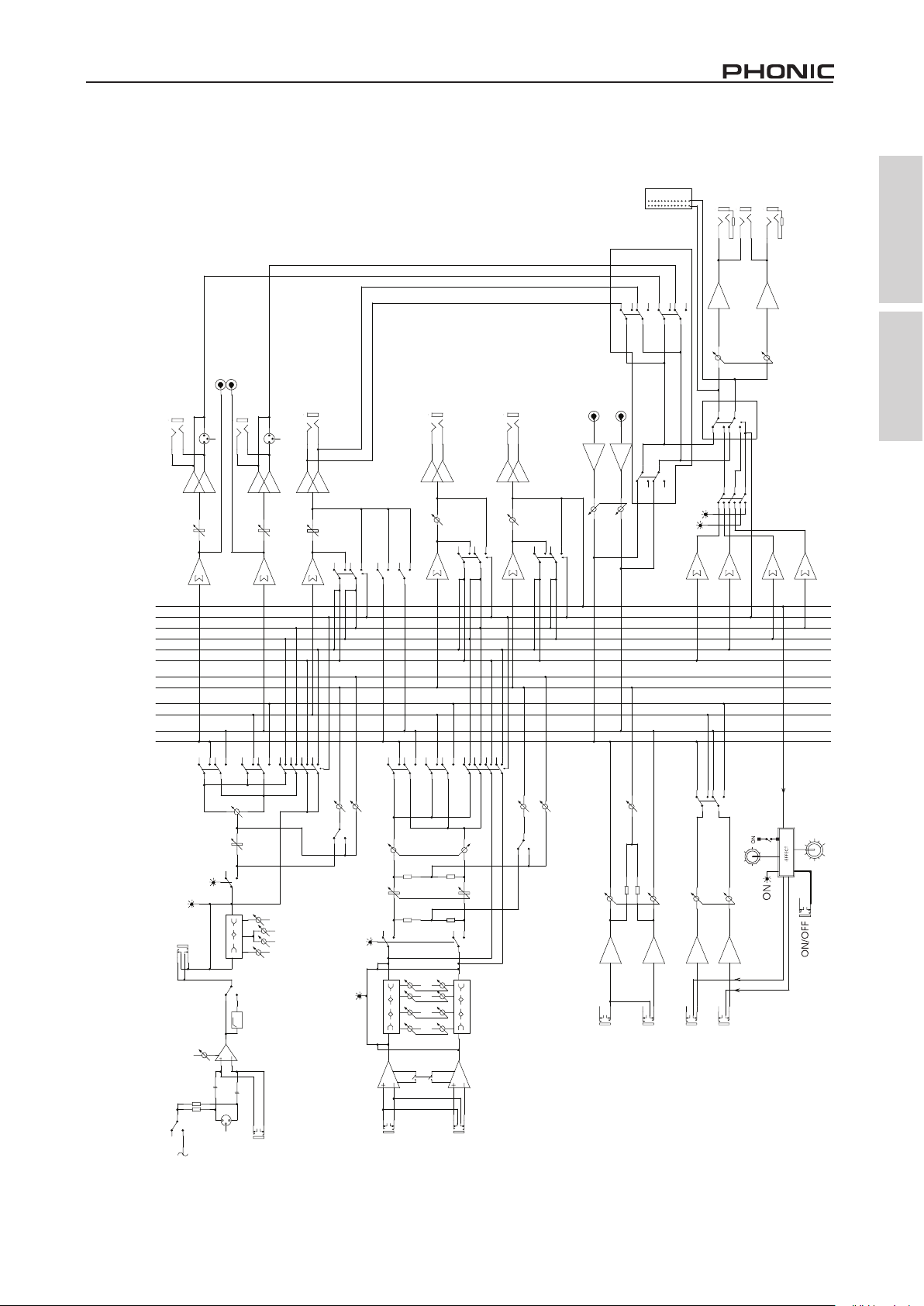
BLOCK DIAGRAM DIAGRAMA DE BLOQUE
AM642D
TUO CER
L MR LRTC
V577.0=uBd0
KAEP
01-
04-
03-
02-
01+
2+
7-
4+
2-
7+
4-
0
NIAM
2/1PG
R MR LRTC
SENOHP
/MR LRTC
SENOHP
Appendix Apéndice
EFX IN
LOGIC
POST R
POST L
PRE R
PRE L
AUX2 EFX
AUX1
GP2
GP1
MAIN R
MAIN L
NTR T2
L NIAM
23
R NIAM
2,1PG
23
1
1
1DNES XUA
2DNES XUA
L
2DNES XUA
REDAF L
REDAF R
REDAF
OLOS
TFEL
1DNES XUA
OLOS
THGIR
OLOS
NTR T2
ECRUOS
R
)DER(TSOP
)NRG(ERP
LRTC_OLOS
TSOP/ERP
XIM NIAM
2/1PG
R/L
NAP
REDAF
OLOS
XFE/2XUA
R/L
1 XUA
2/1PG
OLOS
.LAB
XFE/2UA
1XUA
TSOP
ERP
1XUA OT
2,1PG/NIAM
PSD
MARGORP
)OLOS(KAEP
NO
NO
08001K8K21
OLDIMIH
TRESNI
QE
zH57
NIAG
QERF
DIM
TUC WOL
FPH
4~1 LENNAHC ONOM
)HCTIWS LABOLG(
REWOP MOTNAHP
23
.RWP.HP
1
NI CIM
NI ENIL
AM642D / AM642DP / AM642D USB
REDAF
NO
)OLOS(KAEP
08K21
OLDIMLIH
008
QE
DIMH
K3
01-/4+
)ONOM(L
NO
08K21
OLDIMLIH
008
DIMH
K3
21~5LENNAHC OERETS
R
1NTR
)ONOM(L
1NTR XUA
2NTR
R
PARAMETER
L
R
2NTR XUA
16
3
Page 34

Appendix Apéndice
AUX3 EFX
V
MARGORP
AM642DP
5 7 7 . 0 = u B d 0
K A E P
0 4 -
0 3 -
0 2 -
0 1 -
0 1 +
2 +
4 -
2 -
4 +
7 +
7 -
R T U O C E R
L T U O C E R
T U O R N I A M
T U O L N I A M
0
L M R L R T C
R M R L R T C
S E N O H P
M A R G A I D K C O L B P D 2 4 6 M A
EFX IN
LOGIC
POST R
POST L
PRE R
PRE L
AUX2
AUX1
GP2
GP1
MAIN R
MAIN L
1 D N E S X U A
) X F E O T 3 X U A Y L N O , L A C I T N E D I D N E S 2 X U A (
D N E S 3 X U A
R E D A F 1 X U A
2 3
2
1
1
3
R E D A F L
R E D A F R
1 X U A / N I A M
) L A C I T N E D I T U O 2 P G (
T U O 1 P G
L N T R T 2
R N T R T 2
N T R T 2
/ M R L R T C
S E N O H P
N O
L R T C _ O L O S
M R L R T C O T
R E D A F 1 P G
N O
D N E S 3 X U A
O L O S
O L O S
5 1 3 0 8 K 0 1 K 5 2 . 1 0 3 6 0 6 1 K 6 1 K 5 K 5 . 2
5 1 3 0 8 K 0 1 K 5 2 . 1 0 3 6 0 6 1 K 6 1 K 5 K 5 . 2
T H G I R
T F E L
) D E R ( T S O P
T S O P / E R P
) N R G ( E R P
X I M N I A M
2 / 1 P G
R / L
N A P
R E D A F
) O L O S ( K A E P
N O
0 8 0 0 1 K 8 K 2 1
O L D I M I H
T R E S N I
Q E
O L O S
1 X U A
N O
Q E R F
D I M
R / L
2 / 1 P G
2 X U A
X F E / 3 X U A
O L O S
. L A B
R E D A F
N O
N O
X F E / 3 U A
1 X U A
2 X U A
T S O P
E R P
1 X U A O T
O L O S
1 N T R
2 / 1 P G
R / L
1 X U A O T
N O
O L O S
R E D A F 2 N T R
PSD
16
PARAMETER
) O L O S ( K A E P
0 8 K 2 1 K 3
T U C W O L
z H 5 7
F P H
) 6 ~ 1 ( L E N N A H C O N O M
N I A G
O L D I M L I H
0 0 8
Q E
D I M H
4 1 ~ 7 L E N N A H C O E R E T S
2 3
1
N I E N I L
N I C I M
V 8 4 +
) O N O M ( L
4
0 8 K 2 1 K 3
O L D I M L I H
0 0 8
D I M H
) O N O M ( L
1 N T R X U A
R
0 1 - / 4 +
+
Y A L P
E S U 0 1 ~ 9 H C
B S U / 3 P M / D S
R
2 N T R X U A
L
R
AM642D / AM642DP / AM642D USB
Page 35

AM642D USB
AUX3 EFX
V
MARGORP
AUX SEND1
Appendix Apéndice
0
-2
-10+4+10
+7
+2
-4
-7
-40
-30
-20
PEAK
0dBu=0.775
REC OUT R
REC OUT L
MAIN R OUT
MAIN L OUT
23
2
1
1
3
USB
PORT
TO PC
USB MODULE
2T RTN R
2T RTN L
CTRL RM L
PHONES
CTRL RM R
AUX3 SEND
(AUX2 SEND IDENTICAL,ONLY AUX3 TO EFX)
AM642D USB BLOCK DIAGRAM
SOLO
AUX3 SEND
EFX IN
LOGIC
POST R
POST L
PRE R
PRE L
AUX2
AUX1
GP2
GP1
MAIN R
MAIN L
L/R
PAN
FADER
ON
PEAK(SOLO)
LOMIDHI
EQ
INSERT
75Hz
COMP
GAIN
AUX1 FADER
ON
SOLO
GP1/2
ON
801008K12K
FREQ
MID
HPF
LOW CUT
MONO CHANNEL (1OF6)
L FADER
MAIN/AUX1
ON
R FADER
2T RTN
CTRL RM/
PHONES
GP1 OUT
(GP2 OUT IDENTICAL)
SOLO_CTRL
TO CTRL RM
GP1 FADER
80 315160 630 1.25K10K2.5K5K 16K
80 315160 630 1.25K10K2.5K5K 16K
LEFT
POST(RED)
RIGHT
PRE(GRN)
PRE/POST
MAIN MIX
AUX 2
AUX3/EFX
ON
PEAK(SOLO)
FADER
EQ
L/R
GP1/2
BAL.
SOLO
AUX1
AUX2
PRE
AU3/EFX
POST
TO AUX1
SOLO
RTN1
ON
8012K 3K
LOLMIDHI
800
HMID
8012K
LOLMIDHI
800
3K
HMID
L(MONO)
+4/-10
AUX RTN1
SOLO
AUX 1
R
GP1/2
TO AUX1
ON
L
AUX RTN2
L/R
SOLO
RTN2 FADER
PSD
16
PARAMETER
R
23
1
LINE IN
MIC IN
+48V
AM642D / AM642DP / AM642D USB
R
L(MONO)
STEREO CHANNEL7~14
5
Page 36

 Loading...