

Page 1

(1*/,6+
$
237,0,=(5
Page 2

1. Re ad the se ins tr uc ti on s be fore o pe ra ti ng t hi s
apparatus.
2. Keep these instructions for future reference.
3. Heed all warnings to ensure safe operation.
4. Follow all instructions provided in this document.
5. Do not use this apparatus near water or in locations
where condensation may occur.
6. Clean only with dry cloth. Do not use aerosol or liquid
cleaners. Unplug this apparatus before cleaning.
7. Do not block any of the ventilation openings. Install
in accordance with the manufacturer’s instructions.
8. Do not install near any heat sources such as radiators,
heat registers, stoves, or other apparatus (including
.
9. Do not defeat the safety purpose of the polarized or
grounding-type plug. A polarized plug has two blades
with one wider than the other. A grounding type plug
has two blades and a third grounding prong. The wide
blade or the third prong is provided for your safety. If
the provided plug does not into your outlet, consult
an electrician for replacement of the obsolete outlet.
10. Protect the power cord from being walked on or
pinched particularly at plug, convenience receptacles,
and the point where they exit from the apparatus.
11. Only use attachments/accessories by the
manufacturer.
12. Use only with a cart, stand , tripod, bracket, or
table by the manufacturer, or sold with
the apparatus. When a cart is used, use caution
wh en mov in g the cart/apparatus
combination to avoid injury from tipover.
13. Unplug this apparatus during lighting
st or ms or when unused for lon g
periods of time.
14. Refer all servicing to service personnel.
Servicing is required when the apparatus has been
damaged in any way, such as power-supply cord or
plug is damaged, liquid has been spilled or objects
have fallen into the apparatus, the apparatus has
been exposed to rain or moisture, does not operate
normally, or has been dropped.
IMPORTANT SAFETY INSTRUCTIONS
CAUTION: TO REDUCE THE RISK OF ELECTRIC SHOCK,
DO NOT REMOVE COVER (OR BACK)
NO USER SERVICEABLE PARTS INSIDE
REFER SERVICING TO QUALIFIED PERSONNEL
The lightning flash with arrowhead symbol, within an
equilateral triangle, is intended to alert the user to the
presence of uninsulated “dangerous voltage” within the
product
’
magnitude to constitute a risk of electric shock to persons.
The exclamation point within an equilateral triangle is in-
tended to alert the user to the presence of important operat-
ing and maintenance (servicing) instructions in the literature
accompanying the appliance.
WARNING: To reduce the risk of or electric shock, do
not expose this apparatus to rain or moisture.
CAUTION: Use of controls or adjustments or performance
of procedures other than those may result in
hazardous radiation exposure.
The apparatus shall not be exposed to dripping or splashing and that no objects with liquids, such as vases,
shall be placed on the apparatus. The MAINS plug is used as the disconnect device, the disconnect device shall
remain readily operable.
Warning: the user shall not place this apparatus in the area during the operation so that the mains switch
can be easily accessible.
CAUTION
RISK OF ELECTRIC SHOCK
DO NOT OPEN
Page 3

TABLE OF CONTENTS
INTRODUCTION................................4
FEATURES ........................................4
CONTROLS & CONNECTIONS ........5
APPLICATIONS .................................7
BLOCK DIAGRAM............................8
DIMENSIONS.....................................9
SPECIFICATIONS............................10
APPENDIX: Typical Connectors....11
Page 4

PHONIC CORPORATIONA6500 USER’S MANUALPage 4
INTRODUCTION
Thank you for choosing a Phonic professional
audio product. The A6500 OPTIMIZER is a
new generation two-channel audio compressor
featuring dual-band controls with variable
crossover frequency. Each band has its own
independent controls for compression threshold,
ratio, and attack time. The LED meters provide
immediate display of the input, output, and gain
reduction levels. A bypass switch in each channel
allows quick comparison between the processed
and unprocessed signals. The LINK option allows
simultaneous control of both channels.
The dynamic controls on the OPTIMIZER
effectively eliminate the excessive signal level
from microphones or other sources in a live
event or studio recording session, making
this compressor an indispensable tool for any
professional audio engineer.
This manual is designed to be both concise
and comprehensive. It is concise, so you
can quickly start using your new gear. It is
also comprehensive, so you can gain a full
understanding of the fi ne equipment that you
have just purchased. We hope you will soon
discover that you have made a wise investment
in buying a Phonic product.
FEATURES
• Full-feature two-channel dual-band
compressor
• Variable crossover for user-defi ned
frequency bands
• Independent compression controls for low
and high bands
• 8-segment LED meters for displaying channel
output level and band-specifi c input and gain
reduction levels
• Illuminated function buttons
• Channel-link function
• Relay controlled bypass
• Balanced XLR and 1/4” TRS connectors for
input and output
• Operating levels of +4 dBu and -10 dBV
independently selectable for input and output
• Shielded toroidal power transformer
guarantying minimal interference noise
INTRODUCTION / FEATURES
Page 5
A6500 USER’S MANUALPHONIC CORPORATION
Page 5
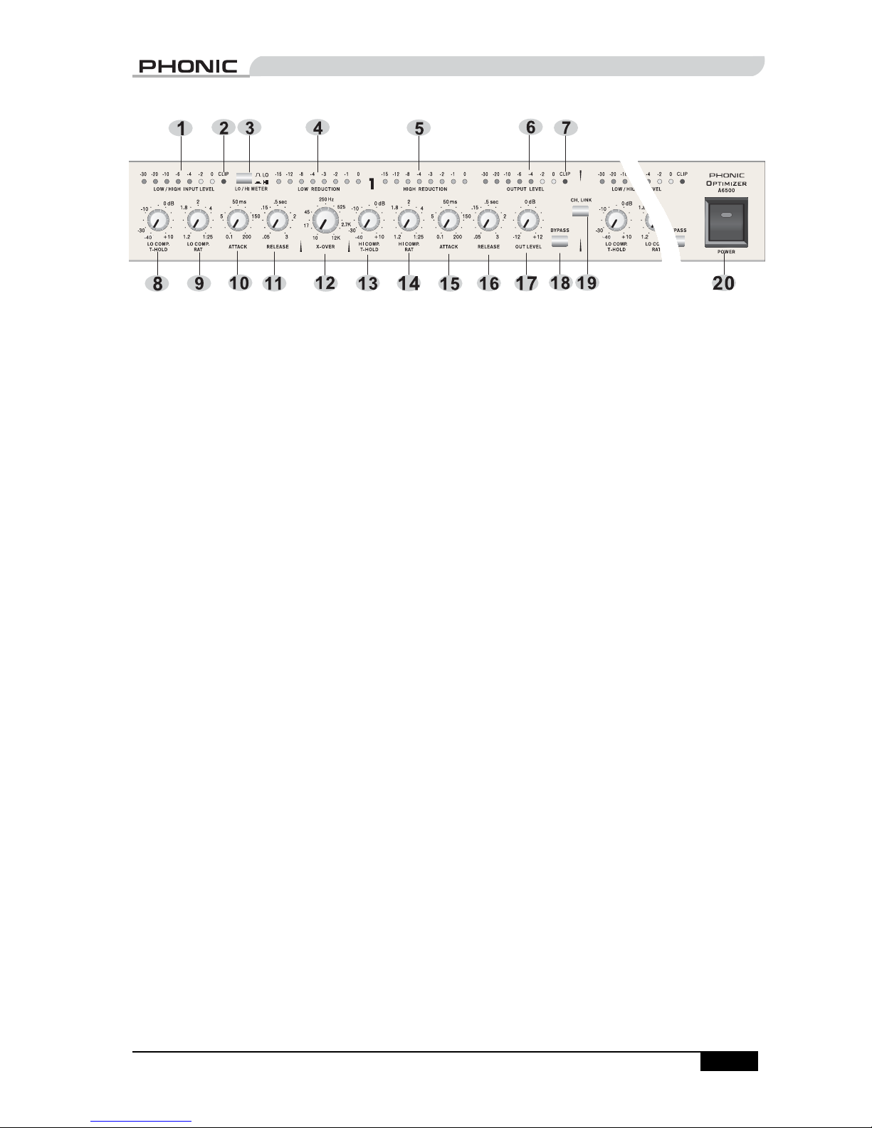
CONTROLS & CONNECTIONS
The OPTIMIZER has two channels which have
identical controls and connections. The following
descriptions apply to both channels.
Front Panel
1. LOW/HIGH INPUT LEVEL meter
This 8-segment LED meter displays the input
level of either the low band or the high band,
depending on the setting of the LO/HI METER
button.
2. (Input) CLIP indicator
This LED indicator lights up when clipping
occurs at either the low band or the high band,
depending on the setting of the LO/HI METER
button. If this indicator lights up frequently, reduce
the input level from the source device to prevent
audio distortion.
3. LO/HI METER button
When this toggle button is depressed, the LOW/
HIGH INPUT LEVEL meter and the (input) CLIP
indicator display the status of the high band.
When the button is released, the LOW/HIGH
INPUT LEVEL meter and the (input) CLIP
indicator display the status of the low band.
4. LOW REDUCTION meter
This 8-segment LED meter displays the amount
of gain reduction occurring at the low band.
5. HIGH REDUCTION meter
This 8-segment LED meter displays the amount
of gain reduction occurring at the high band.
6. OUTPUT LEVEL meter
This 8-segment LED meter displays the level of
the channel output.
7. (Output) CLIP indicator
This LED indicator lights up when clipping occurs
at the channel output. If this indicator lights up
frequently, reduce the output level to prevent
audio distortion.
8. LO COMP. T-HOLD control
This control knob adjusts the compression
threshold of the low band. All signals above the
set level are compressed. The threshold for the
low band can be set at any level between -40 and
+10 dB.
9. LO COMP. RAT control
This control knob determines the compression
ratio for the low band, ranging from 1:1.2 to 1:25.
10. (Low) ATTACK control
This control knob determines the speed with
which the compression for the low band
begins after the input level has exceeded the
threshold. The range of control is from 0.1 to 200
milliseconds.
11. (Low) RELEASE control
This control knob determines the speed with
which the compression for the low band ceases
after the input level has fallen below the
threshold. The range of control is from 0.05 to 3
seconds.
12. X-OVER control
This control knob determines the crossover
frequency, or the frequency at which the low and
high bands are separated. The crossover can be
set at any frequency between 10 Hz and 12 kHz.
13. HI COMP. T-HOLD control
This control knob adjusts the compression
threshold of the high band. All signals above the
set level are compressed. The threshold for the
high band can be set at any level between -40
and +10 dB.
CONTROLS & CONNECTIONS
Page 6

PHONIC CORPORATIONA6500 USER’S MANUALPage 6
14. HI COMP. RAT control
This control knob determines the compression
ratio for the high band, ranging from 1:1.2 to
1:25.
15. (High) ATTACK control
This control knob determines the speed with
which the compression for the high band
begins after the input level has exceeded the
threshold. The range of control is from 0.1 to 200
milliseconds.
16. (High) RELEASE control
This control knob determines the speed with
which the compression for the high band
ceases after the input level has fallen below the
threshold. The range of control is from 0.05 to 3
seconds.
17. OUT LEVEL control
This control knob adjusts the level of the
channel output. The range of control is from -12
to +12 dB.
18. BYPASS button
This toggle button determines whether the signal
from the channel input should be processed
(released) or unaltered (depressed) before it is
sent to the channel output. The bypass function is
useful for a quick comparison between processed
and unprocessed sounds.
19. CH. LINK button
This toggle button determines whether Channel
1 and Channel 2 are to be controlled separately
(released) or in sync (depressed). When the
button is depressed, the settings for Channel 1
are applied to both channels.
20. POWER button
This toggle button turns on the OPTIMIZER when
depressed, and turns it off when released.
Back Panel
21. INPUT connectors
The input connection is equipped with a female
XLR and a 1/4" TRS jack. Both connectors are
balanced.
22. Nominal operating level (IN)
This toggle button determines the nominal
operating level of the input (-10 dBV when
depressed, and +4 dBu when released). This
setting should match the nominal operating
level of the source device. In general, consumer
products use -10 dBV, while professional
products use +4 dBu.
23. Nominal operating level (OUT)
This toggle button determines the nominal
operating level of the output (-10 dBV when
depressed, and +4 dBu when released). This
setting should match the nominal operating
level of the target device. In general, consumer
products use -10 dBV, while professional
products use +4 dBu.
24. OUTPUT connectors
The output connection is equipped with a male
XLR and a 1/4" TRS jack. Both connectors are
balanced.
25. Power inlet and fuse holder
Use the supplied power cord to connect the
OPTIMIZER to an AC power outlet of a suitable
voltage. To change the fuse, use a screwdriver to
slide open the fuse cover, then replace the fuse
with one that is of identical type.
CONTROLS & CONNECTIONS
Page 7
A6500 USER’S MANUALPHONIC CORPORATION
Page 7
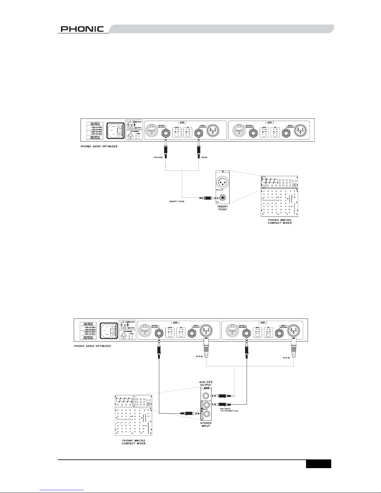
APPLICATIONS
This section presents two typical methods for connecting the OPTIMIZER to a mixer.
By using a insert point
If your mixer has a insert point, you can process the signal from that insert point by connecting the
OPTIMIZER to the insert point via an insert cord. See “Appendix: Typical Connectors” for an illustration of
some insert cords.
By using an input channel
If your mixer does not have an insert point, or if you have used all available insert points, you may use
one of the input channels as a return input. Follow these steps:
1. Connect the AUX (or EFX) output of your mixer to the input of the OPTIMIZER.
2. Connect the output of OPTIMIZER to one of the input channels of the mixer.
3. To prevent feedback, mute the AUX-send (or EFX-send) of the channel that is receiving its input
from the OPTIMIZER.
Through this routing, the original signal is sent from the mixer to the OPTIMIZER for processing. The
processed signal is then sent back to the mixer for mixing.
APPLICATIONS
Page 8
PHONIC CORPORATIONA6500 USER’S MANUALPage 8
LOW LEVEL
LOW
LEVEL
HIGH COMP
HIGH
COMP
X-OVER FREQ
X-OVER
FREQ
VCA
LEVEL
HIGH LEVEL
HIGH
LEVEL
INPUT
VCA
VCA
RELEASE
HIGH GAIN
HIGH
GAIN
THRESHOLD
ATTACK
LOW LEVEL
LOW
LEVEL
+4/-10dB
LOW COMP
LOW
COMP
LOW GAIN
LOW
GAIN
output
+
+4/-10dB
+4/-10dB
+4/-10dB
THRESHOLD
RATIO
RATIO
ATTACK
RATIO
THRESHOLD
FILTER
RATIO
MUTE
LOW GAIN
LOW
GAIN
MUTE
LEVEL
HIGH GAIN
HIGH
GAIN
THRESHOLD
K1
INPUT
ATTACK
MUTE
LOW COMP
LOW
COMP
STEREO LINK
STEREO
LINK
+
HIGH COMP
HIGH
COMP
BYPASS
HIGH LEVEL
HIGH
LEVEL
RELEASE
X-OVER FREQ
X-OVER
FREQ
BYPASS
X-OVER FREQ
X-OVER
FREQ
ATTACK
output
VCA
FILTER
MUTE
RELEASE
RELEASE
V+
V+
3
4
5
6
8
7
1
2
3
4
5
6
8
7
1
2
+
-
+
-
HIGH
LOW
CHANNEL 1
CHANNEL 1
CHANNEL 2
CHANNEL 2
+
LOW
HIGH
+
-
-
CH2_H
CH2_L
CH2_H
CH2_L
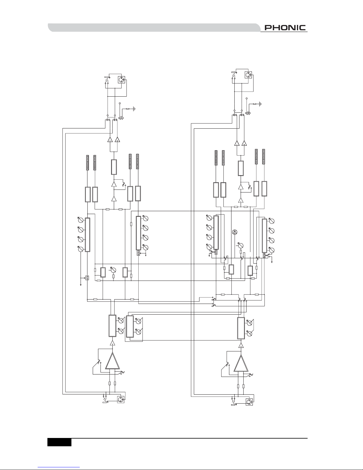
BLOCK DIAGRAM
BLOCK DIAGRAM
Page 9

A6500 USER’S MANUALPHONIC CORPORATION
Page 9
DIMENSIONS
DIMENSIONS
Page 10

PHONIC CORPORATIONA6500 USER’S MANUALPage 10
Input
Connectors XLR and 1/4" TRS
Type RF fi ltered, balanced input
Impedance 20k ohms balanced, 10k ohms unbalanced
Nominal Operating Level -10 dBu and +4 dBu, selectable
Maximum Input Level +14 dBu
Output
Connectors XLR and 1/4" TRS
Type RF fi ltered, balanced output
Impedance 200 ohms balanced, 100 ohms unbalanced
Nominal Operating Level -10 dBu and +4 dBu, selectable
Maximum Output Level +14 dBu
System
Bandwidth 20 Hz to 20 kHz, 0 dB/-0.5 dB
Noise < -90 dB
THD + Noise 0.04% at 0 dB, 1 kHz
Crosstalk < -80 dB
Compressor
Crossover 10 Hz to 12 kHz
Threshold Low/High variable from -30 dB to +10 dB
Attack Variable (0.1 ms/20 dB to 200 ms/20 dB)
Release Variable (0.05 ms/20 dB to 3 s/20 dB)
Ratio Low/High 1:2 to 1:25
Output Level +/- 12 dB
Power Supply
Power Consumption 10 W
Power Connector Standard IEC connector
Operating Voltages 100V AC 50/60Hz, 120V AC 60Hz, 240V AC 50Hz
Fuse 100-120 V: 1 A / 250 V
200-240 V: 500 mA / 250 V
Physical
Dimension (W x H x D) Approx. 482 x 44 x 204 mm (19 x 1.75 x 8 in.)
Weight Approx. 2.7 kg (6.0 lbs.)
SPECIFICATIONS
SPECIFICATIONS
Page 11

A6500 USER’S MANUALPHONIC CORPORATION
Page 11
APPENDIX: TYPICAL CONNECTORS
Tip
Tip
Tip
Tip
Tip
Tip
Tip
Tip
Tip
Tip
Tip
Tip
Tip(Send)
Centre(Send)
Tip(Return)
Centre(Return)
Tip
Tip
1
1
1
Centre
Centre
Screen
Screen
1
1
1
1
1
1
Ring
Ring
Ring
Ring
Ring
Ring
Ring
Ring
2
2
2
2
2
2(Return)
2(Send)
2
2
3
3
3
3
3
3
3
3
3
1
2
3
1
2
3
Sleeve
Sleeve
Sleeve
Sleeve
Sleeve
Sleeve
Sleeve
Sleeve
Sleeve
Sleeve
Sleeve
Sleeve
Sleeve
Screen
Sleeve
Screen
Sleeve
Sleeve
B
A
L
A
N
C
E
D
U
N
B
A
L
A
N
C
E
D
I
N
S
E
R
T
C
O
R
D
Tip
1
2
XLR-F
3
11
2
3
XLR-M
11
2
3
XLR-M
11
2
3
XLR-M
11
2
3
XLR-M
11
2
3
XLR-M
11
2
3
XLR-M
1
2
XLR-F
3
1
2
XLR-F
3
11
2
3
XLR-M
11
2
3
XLR-M
11
2
3
XLR-M
11
2
3
XLR-M
XLR-F
1
2
3
1
2
XLR-F
3
11
2
3
XLR-M
1
2
XLR-F
3
11
2
3
XLR-M
1
2
XLR-F
3
11
2
3
XLR-M
Tip
Tip
Tip
Tip
Tip
Tip
Tip
Tip
Tip
Tip
Centre
Centre
Tip
Tip
Tip
Tip
Tip
1
1
1
1
1
1
1
Ring
Ring
Ring
Ring
Ring
Ring
Ring
Ring
Ring
Ring
2
2
2
2
2
2
2
3
3
3
3
3
3
3
Sleeve
Sleeve
Sleeve
Sleeve
Sleeve
Ring
Sleeve
Sleeve
Sleeve
Sleeve
Screen
Screen
Sleeve
Sleeve
Sleeve
Sleeve
Sleeve
B
A
L
A
N
C
E
D
U
N
B
A
L
A
N
C
E
D
Y
C
O
R
D
Y
C
O
R
D
H
E
A
D
P
H
O
N
E
S
P
L
I
T
E
R
1
2
XLR-F
3
11
2
3
XLR-M
11
2
3
XLR-M
11
2
3
11
2
3
XLR-M
11
2
3
XLR-M
11
2
3
XLR-M
11
2
3
XLR-M
11
2
3
XLR-M
11
2
3
XLR-M
11
2
3
XLR-M
APPENDIX
Page 12
6103 Johns Road #7
Page 13

 Loading...