

Page 1

SYSTEM MANUAL
SOFTWARE
BV FAMILY - RELEASE 1.2
SYSTEM MANUALS (VOLUME 1 OF 2)
FILING INSTRUCTIONS
This manual should be filed in:
SYSTEM MANUALS BV Family - RELEASE 1.2
VOLUME 1 OF 2
Snij-lijn
BV Family R1.2 / Volume 1 (04.0) SM – SW 0.5
Copyright © 2004 Koninklijke Philips Electronics N.V.
ALL RIGHTS RESERVED
SYSTEM MANUAL SOFTWARE – BV FAMILY RELEASE 1.2
Page 2
PHILIPS
PHILIPS
SOFTWARE
INSTALLATION
BV-SCOPE
MENU ITEMS
1
2
➤
➤
PHILIPS MEDICAL SYSTEMS
S
y
s
t
e
m
M
a
n
u
a
l
S
y
s
t
S
e
y
s
t
e
SSooffttwwaarree
Software
m
m
M
M
a
a
n
n
u
u
a
a
l
l
DICOM
CONFIGURATION
3
➤
4
➤
5
➤
6
➤
7
➤
8
➤
PMSN Best
Reproduction in whole or in part is prohibited without the written consent of
the copyright owner. Use of the information contained herein in any form
and/or by any means whatsoever is strictly reserved for Philips and its
licencees. Use of this manual by unauthorised persons is strictly prohibited.
Printed in Best, Netherlands.
BV Family R1.2 / Volume 1 (04.0) SM – SW 1
Copyright © 2004 Koninklijke Philips Electronics N.V.
ALL RIGHTS RESERVED
9
10
➤
➤
Page 3

Service Manual BV Family R1.2
y
SERVICE MANUAL - SYSTEM: BV Famil
RELEASE 1.2 SOFTWARE
SYSTEM: BV Family R1.2
TYPE NO:
Manual Code Number 4522 981 22636 Date: 15-March-2005
LIST OF PAGES and DRAWINGS
0.5 (04.0)
1 (04.0)
2.1 (05.0) *
SM-SW 1-1 … 18 (04.2)
SM-SW 2-1 … 25 (05.0)
SM-SW 3-1 … 26 (04.1)
BV Family R1.2 / Volume 1 (05.0) SM – SW 2.1
ALL RIGHTS RESERVED
Copyright © 2005 Koninklijke Philips Electronics N.V.
Page 4

Service Manual BV Family R1.2 Section 1
Software installation
Section 1 SOFTWARE INSTALLATION
Contents
INTRODUCTION .....................................................................................................................................2
1
2
REQUIREMENTS OF THE SERVICE PC...............................................................................................2
3
CONNECTING THE SERVICE PC TO THE BV FAMILY SYSTEM.......................................................3
4
CONFIGURING THE CONNECTION BETWEEN SERVICE PC AND BV FAMILY SYSTEM ..............5
4.1 Configuration of a connection with a serial cable....................................................................................5
4.2 Configuration of a connection with a cross cable or a network cable....................................................11
5
PREPARATION OF THE SERVICE PC FOR BV-SCOPE...................................................................12
5.1 Configuration of Internet Explorer settings ............................................................................................12
5.2 Configuration of ActiveX control settings...............................................................................................12
5.3 Installation of the BV-Scope hardware key............................................................................................14
5.4 Creating a short cut for BV-Scope.........................................................................................................14
6
DOWNLOADING THE SYSTEM SOFTWARE TO THE BV FAMILY SYSTEM ..................................16
7
PROCEDURES AFTER DFI REPLACEMENT OR SOFTWARE RE-INSTALLATION.......................17
8
INSTALLATION OF EXTRA SOFTWARE OPTIONS..........................................................................18
8.1 Installation procedure ............................................................................................................................18
8.2 Check of new functions after installation of extra software options.......................................................18
BV Family R1.2 / Volume 1 (04.2) SM-SW 1 - 1
ALL RIGHTS RESERVED
© 2004 Koninklijke Philips Electronics N.V.
Page 5

Section 1 Service Manual BV Family R1.2
Software installation
1 INTRODUCTION
This sections deals with the configuration of a connection between the service PC and the BV Family
system in case of BV-Scope with integrated DICOM functions (= performing DICOM functions without
external Merge Box).
NOTE
Systems with an external Merge Box have been delivered with another version of the system software.
These systems have to be configured conform the documentation delivered to those systems.
________________
The service PC and the BV Family system can be connected in 3 ways: with a serial cable, a cross cable and
a network cable. Depending on the way you choose, the service PC has to be configured and prepared. After
this, the system software for the BV Family system can be downloaded from the service PC to the BV Family
system.
CAUTION
Reinstallation / changing software is only allowed by authorized persons.
________________
WARNING
After adjustments of the system always restart the system t o ensure, t he new adjust m ents will be activat ed.
________________
WARNING
Together with a restart of the system, always close BV-scope and restart it.
________________
2 REQUIREMENTS OF THE SERVICE PC
The requirements for the service PC are:
1. Windows 2000 with administrator’s rights.
2. Internet Explorer 5.5 or higher
3. CD-ROM player
4. Ethernet-card (preferred) or serial port
5. A connected hardware key (level 2 for X-ray) with known password (see chapter 5.3 if the hardware key
and its software has not already been installed).
6. PMSSec reader release 2.289 or higher.
Start PMSSec reader to check this.
(Usually this can be done by selecting: Programs > PMS Service Work Bench > PMSSec Reader. The
PMSSec Reader icon appears. Position the pointer on top of the icon. The release no. appears.)
7. Security toolbox release 1.16. or higher.
Start the Security toolbox to check this.
(Usually this can be done by selecting: Programs > PMS Service Work Bench > Security Toolbox. The
Security Toolbox window appears. Select Help > About. The version no. appears.)
8. In case of integrated DICOM functionality: contact the network administrator for an IP address for the
service PC. This is not necessary if for service the service PC will be connected to the BV Family system
with a serial cable.
SM-SW 1 - 2 (04.2) BV Family R1.2 / Volume 1
ALL RIGHTS RESERVED
© 2004 Koninklijke Philips Electronics N.V.
Page 6
Service Manual BV Family R1.2 Section 1
Software installation
3 CONNECTING THE SERVICE PC TO THE BV FAMILY SYSTEM
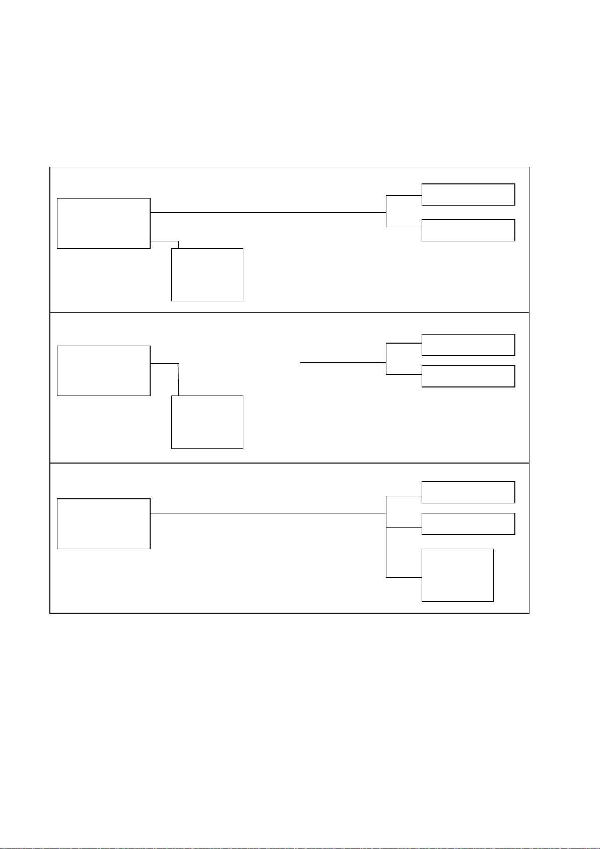
The Service PC can be connected to the BV Family system in 3 ways: with a serial cable, a cross cable and a
network cable. See figure below. For the consequences, see the table below.
Connection with a serial cable (recommended connection for service)
BV Fam. System
(DFI in MVS)
Serial cable
Service PC
with
BV-Scope
interface
Connection with a cross cable
BV Fam. System
(DFI in MVS)
Cross cable
Service PC
with
BV-Scope
interface
Connection with a network cable
BV Fam. System
(DFI in MVS)
Network cable
(only for DICOM
functions)
Network cable
DICOM Archive
DICOM Printer
DICOM Archive
DICOM Printer
DICOM Archive
DICOM Printer
Service PC
with
BV-Scope
interface
BV Family R1.2 / Volume 1 (04.2) SM-SW 1 - 3
ALL RIGHTS RESERVED
© 2004 Koninklijke Philips Electronics N.V.
Page 7

Section 1 Service Manual BV Family R1.2
Software installation
Possible connections between the Service PC and the BV Family system
Cable Con-
nector
Serial cable,
Serial Yes No, see note 2 Yes, takes about
see note 1
Cross cable,
Ethernet Yes Yes Yes
see note 3
Network cable
Ethernet Yes Yes Yes
Access to BVScope
possible?
Performing of
DICOM functions
possible?
Downloading of
software
20 min.
(about 2 min.)
(about 2 min.)
Type of
connection
Local
(= point to point)
Local
(= point to point)
Network
NOTE 1
Connection with a serial cable is recommended, however see note 2.
________________
NOTE 2
When there is a connection with a serial cable, only service is possible. To perform DICOM functions a
network cable should be used to connect the BV Family system with the DICOM network.
________________
NOTE 3
With a only a cross cable, service of the BV Family system and performing of DICOM functions is not possible
at the same time (except when the DICOM application and BV-scope are running on the same PC).
________________
For the necessary configuration of the connection and the preparation of the service PC for BV-Scope, follow
the next chapters.
SM-SW 1 - 4 (04.2) BV Family R1.2 / Volume 1
ALL RIGHTS RESERVED
© 2004 Koninklijke Philips Electronics N.V.
Page 8
Service Manual BV Family R1.2 Section 1
Software installation
4 CONFIGURING THE CONNECTION BETWEEN SERVICE PC AND BV
FAMILY SYSTEM
The service PC can be connected to the BV Family system in 3 ways: with a serial cable, a cross cable and a
network cable. Configuration with a serial cable is recommended. For the limitations of this connection, refer
to the previous chapter.
4.1 Configuration of a connection with a serial cable p. 5
4.2 Configuration of a connection with a cross cable or a network cable p. 11
4.1 C
This procedure also applies for reinstallation.
1. Connect a serial cable between the service PC and the BV Family system.
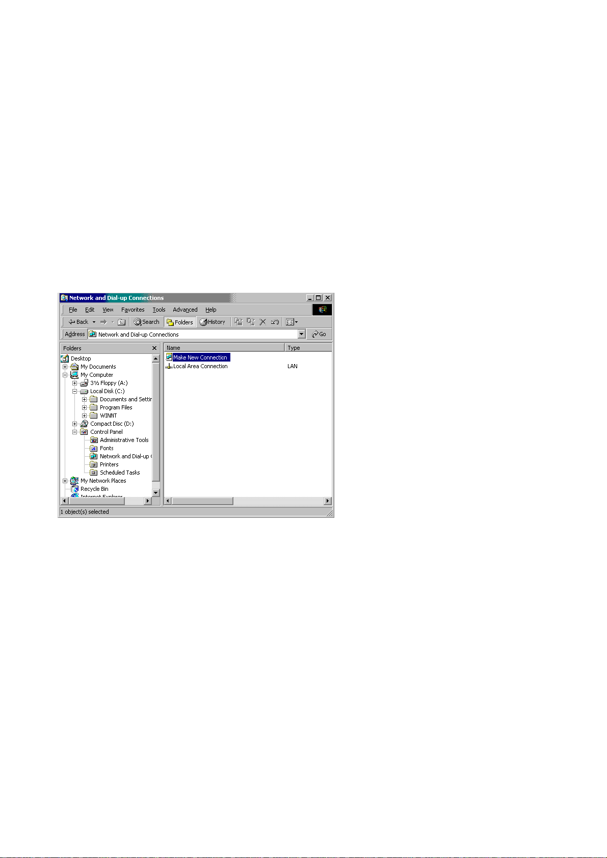
2. Select Start > Settings > Control Panel > Network and Dial-up Connections. The Network and Dial-up
Connections window appears (see figure below).
ONFIGURATION OF A CONNECTION WITH A SERIAL CABLE
3. Double click the Make New Connection icon. If you do this for the first time, the Location Information
window below appears. If this is not the first time, click the Next button and proceed with step 7 below.
BV Family R1.2 / Volume 1 (04.2) SM-SW 1 - 5
© 2004 Koninklijke Philips Electronics N.V.
ALL RIGHTS RESERVED
Page 9
Section 1 Service Manual BV Family R1.2
Software installation
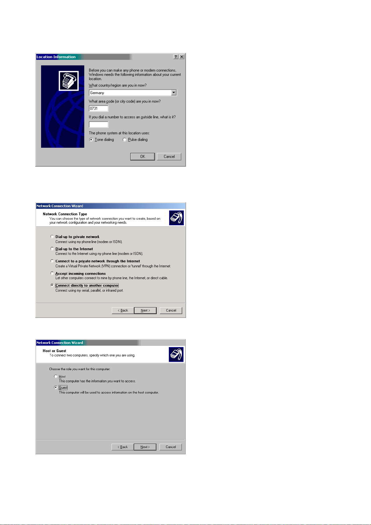
4. In the What country/region are you in now? field, enter just a country.
5. In the What area code (or city code) are you in now? field, enter just 4 digits.
6. Click the OK button. The Network Connection Wizard window appears.
7. Select Connect directly to another computer and click the Next button. The window below appears.
8. Select Guest and click the Next button. The window below appears.
SM-SW 1 - 6 (04.2) BV Family R1.2 / Volume 1
ALL RIGHTS RESERVED
© 2004 Koninklijke Philips Electronics N.V.
Page 10
Service Manual BV Family R1.2 Section 1
Software installation
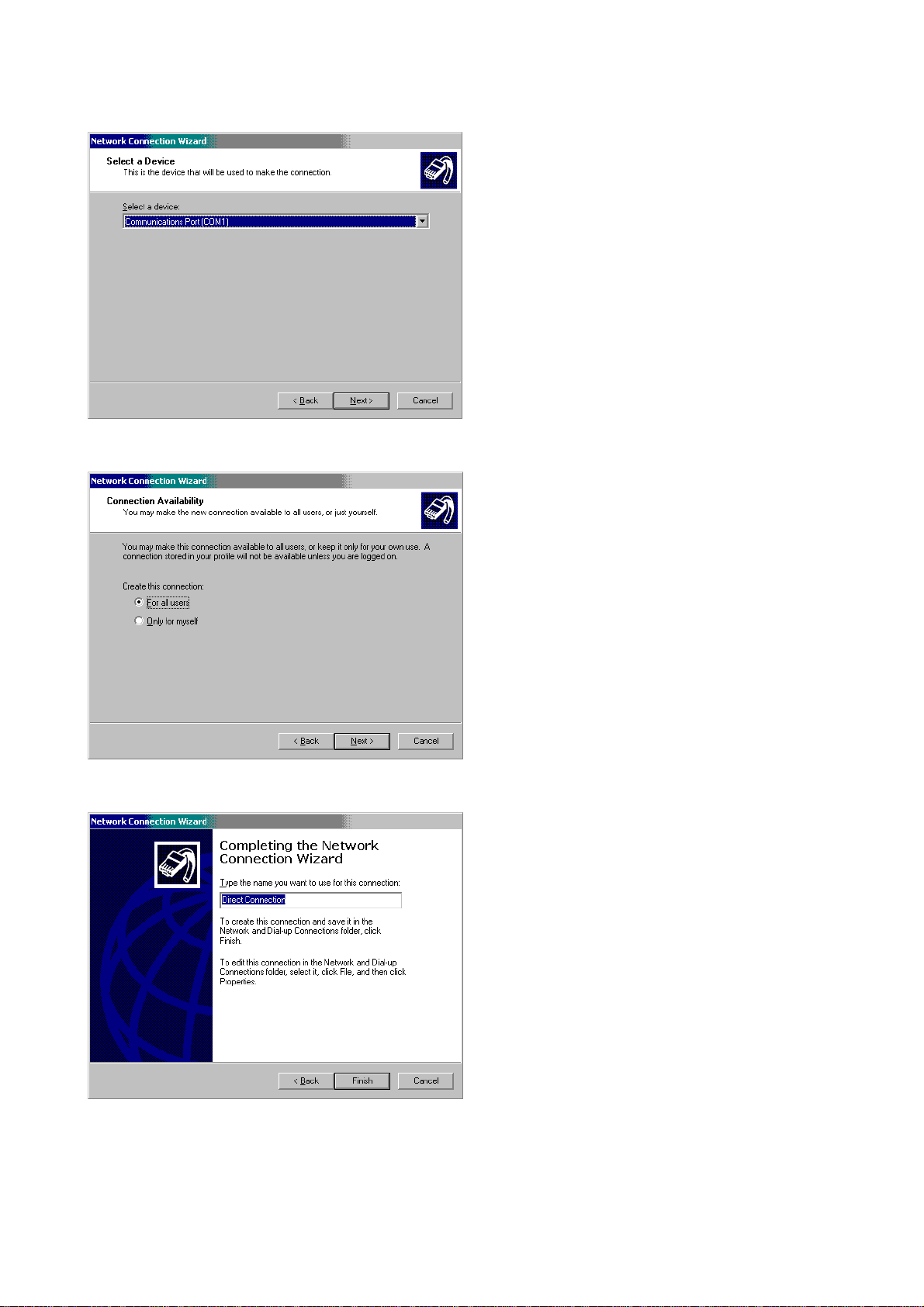
9. Select Communications Port (COM1) and click the Next button. The window below appears
9. Select For all users and click the Next button. The window below appears.
10. Enter a name for your connection.
11. Click the Finish button. The window below appears.
BV Family R1.2 / Volume 1 (04.2) SM-SW 1 - 7
ALL RIGHTS RESERVED
© 2004 Koninklijke Philips Electronics N.V.
Page 11
Section 1 Service Manual BV Family R1.2
Software installation
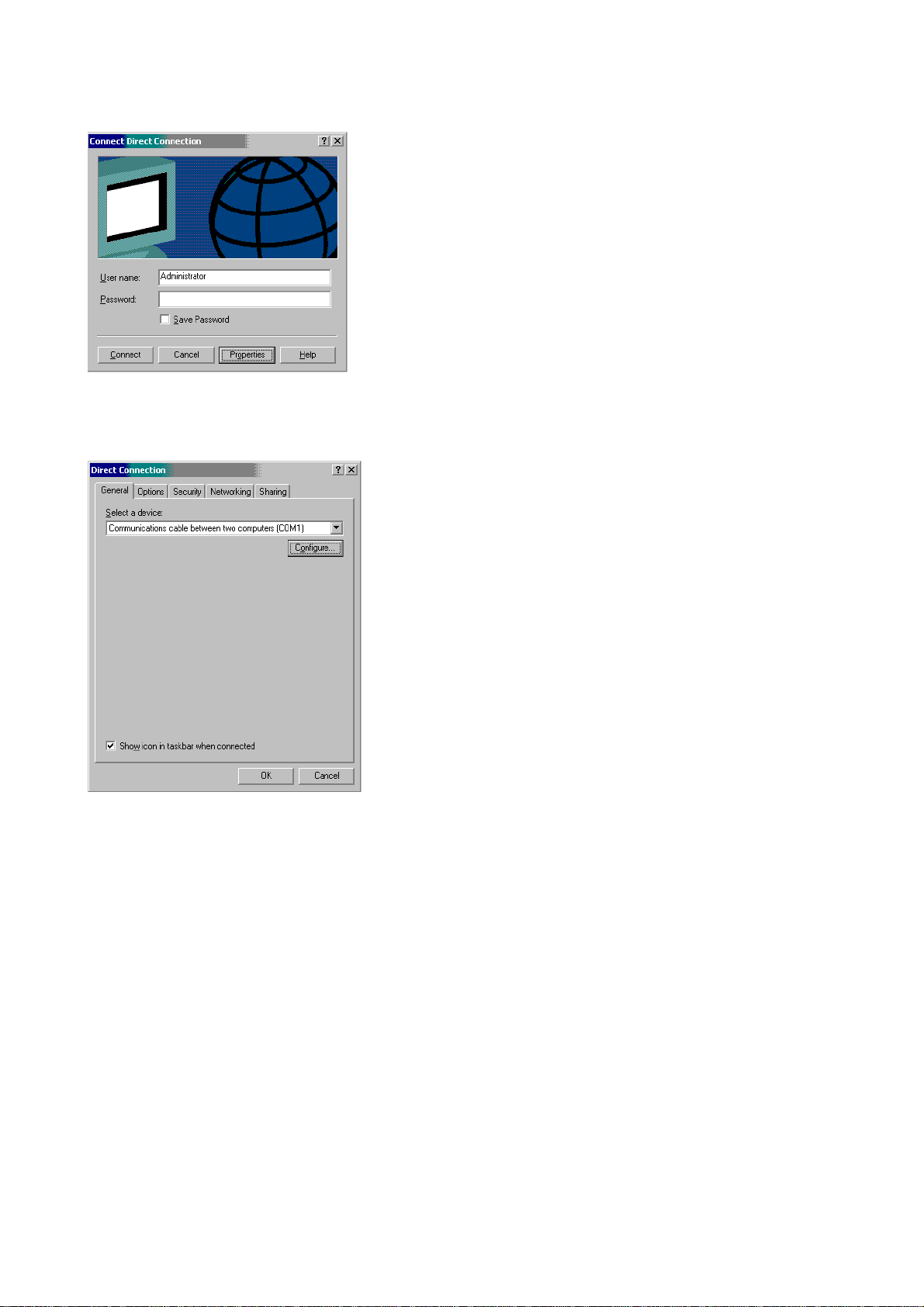
12. Change the User name field to: dfi
13. Change the Password field to: software
14. Click the Properties button. The window below appears.
15. Select Communications cable between two computer (COM1)
16. Click the Configure button. The Modem Configuration window appears.
SM-SW 1 - 8 (04.2) BV Family R1.2 / Volume 1
ALL RIGHTS RESERVED
© 2004 Koninklijke Philips Electronics N.V.
Page 12
Service Manual BV Family R1.2 Section 1
Software installation
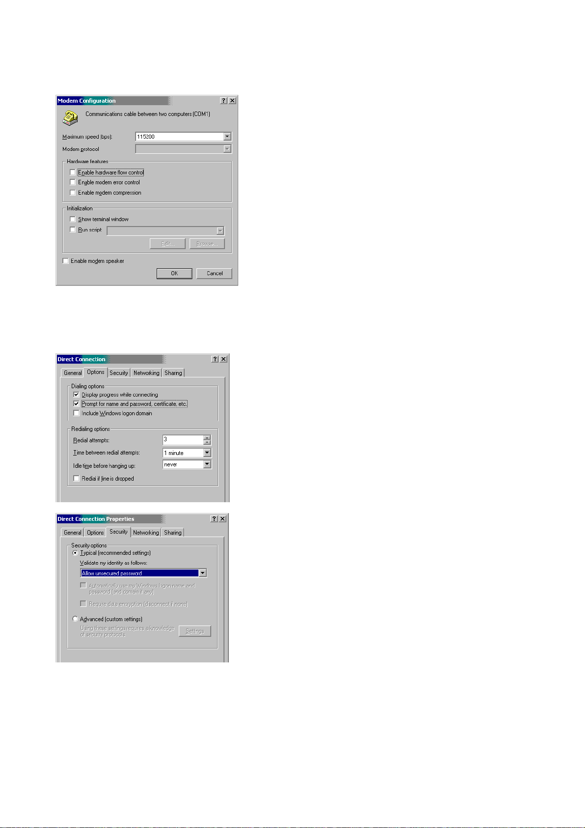
17. In the Maximum speed field select 115200
18. Disable all hardware features.
19. Click the OK button. The window below appears.
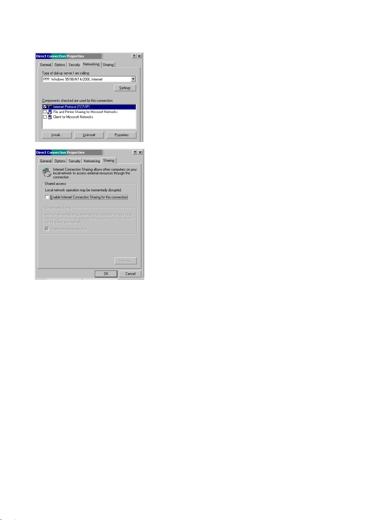
20. Set up the Options, Security, Networking, and Sharing tabs as shown below:
BV Family R1.2 / Volume 1 (04.2) SM-SW 1 - 9
ALL RIGHTS RESERVED
© 2004 Koninklijke Philips Electronics N.V.
Page 13
Section 1 Service Manual BV Family R1.2
Software installation
21. When set up as shown above, click the OK button. The Connect Direct Connection window appears.
22. To start the new connection enter the password and click the Connect button.
To start the new connection from the Desktop, select Start > Settings > Control Panel > Network and Dial-up
Connections and select the connection with the name you entered in step 10 above.
If there are problems with the serial connection:
• Restart MVS.
• Enable Service on the MVS. (To enable service on the MVS refer to chapter 5.4 step 3.)
• Restart the Service PC.
SM-SW 1 - 10 (04.2) BV Family R1.2 / Volume 1
ALL RIGHTS RESERVED
© 2004 Koninklijke Philips Electronics N.V.
Page 14

Service Manual BV Family R1.2 Section 1
Software installation
4.2 C
ONFIGURATION OF A CONNECTION WITH A CROSS CABLE OR A NETWORK CABLE
NOTE
This procedure is not necessary if the service PC will be connected to the BV Family system with a serial
cable.
________________
The settings for the network are described for a Windows 2000 operating system.
1. Start > Settings > Control Panel. The Control Panel window appears.
2. Double click the Network and Dail-up Connections icon. The corresponding window appears.
3. Click with the right mouse button on the Local Area Connection icon. A menu appears.
4. Click Properties. The Local Area Connection Properties window appears.
5. Mark and select Internet Protocol (TCP/IP).
6. Click the Properties button. The Internet Protocol (TCP/IP) Properties window appears.
7. Select Use the following IP Address.
8. Click the Advanced button. The Advanced TCP/IP Settings window appears.
9. Click the upper Add button. The TCP/IP Address window appears.
10. Enter the IP address as shown in the Setup panel of the MVS. (If there is not shown an IP address: enter
the default IP address 192.168.1.1 )
11. Enter the Subnet mask: 255.255.255.0
12. Click the Add button. The Advanced TCP/IP Settings window appears.
13. Click OK. The Internet Protocol (TCP/IP) Properties window appears.
NOTE
If 'Use the following IP address' has been selected for BV-Scope to work and you use VRAS,
then select Obtain IP address automatically.
To use BV-Scope again, select Use the following IP address.
________________
14. Click OK. The Local Area Connection Properties window appears.
15. Click OK. The Network and Dail-up Connections window appears.
16. Close the window.
17. Restart the Service PC.
NOTE
The Network card in the service PC has to communicate with the 10 MB Ethernet connection of the DFI.
Therefore, the communication speed of the network card has to be set at 10 Mbps or at Auto.
________________
BV Family R1.2 / Volume 1 (04.2) SM-SW 1 - 11
ALL RIGHTS RESERVED
© 2004 Koninklijke Philips Electronics N.V.
Page 15
Section 1 Service Manual BV Family R1.2
Software installation
5 PREPARATION OF THE SERVICE PC FOR BV-SCOPE
5.1 C
This procedure has been written for Windows 2000, for other Windows versions, the procedure may differ.
1. Start Internet Explorer.
2. Select Tools > Internet Options. The corresponding window appears.
3. Select the General tab, click the Settings button.
4. Select Automatically, click the OK button.
5. Select the Security tab, click the Trusted sites icon.
6. Click the Sites button. The Trusted sites window appears.
7. Unselect Require server verification…
8. Start the mobile viewing station (MVS). This is necessary to look up an IP address.
9. In the Add this Web site to the zone field enter http:// followed by the IP address of the MVS (This IP
address is shown in the Setup panel of the MVS (the default IP address is 192.168.1.61). The Setup
panel can be reached by clicking the corresponding icon in the Patient Administration screen).
10. Click the Add button.
11. Click the OK button. The Security tab appears.
12. Select the Connections tab.
13. Select Never dial a connection.
14. Click the LAN Settings button. The Local Area Network (LAN) Settings window appears.
15. If Use a proxy server for your LAN has been selected, click the Advanced button. If not: go to step 18.
16. In the Exception panel, enter the IP address of the MVS.
17. Click the OK button.
18. Close all windows using the OK buttons. The entered values will be stored.
5.2 C
ONFIGURATION OF INTERNET EXPLORER SETTINGS
ONFIGURATION OF ACTIVEX CONTROL SETTINGS
ActiveX controls must be enabled to readout the hardware key (dongle). Check the settings as follows:
1. Start Internet Explorer.
2. Select Tools > Internet Options. The corresponding window appears.
3. Select the Security tab, the corresponding tab appears.
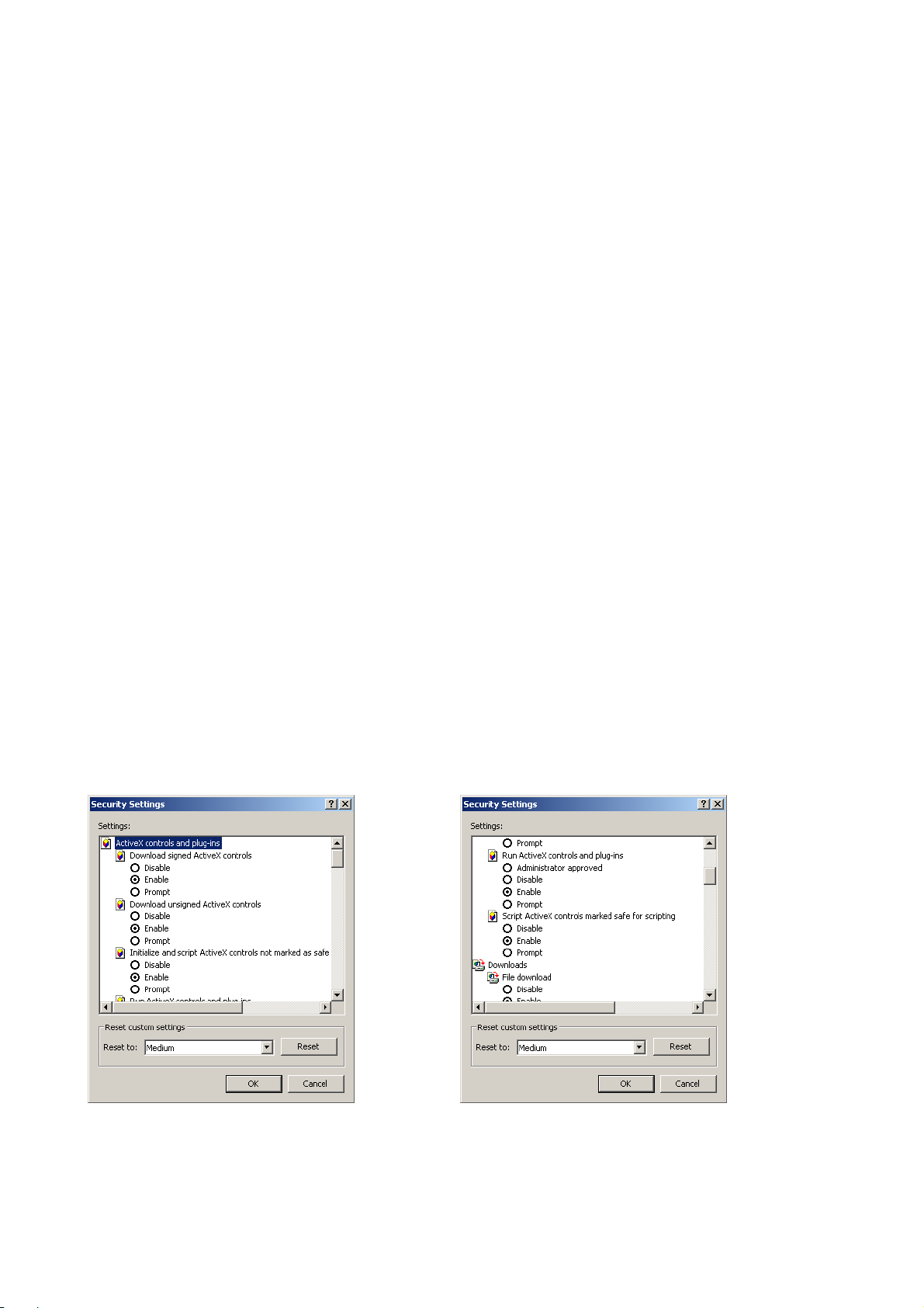
4. Click the Custom Level… button. The Security Settings window appears, see figure below.
SM-SW 1 - 12 (04.2) BV Family R1.2 / Volume 1
ALL RIGHTS RESERVED
© 2004 Koninklijke Philips Electronics N.V.
Page 16
Service Manual BV Family R1.2 Section 1
Software installation
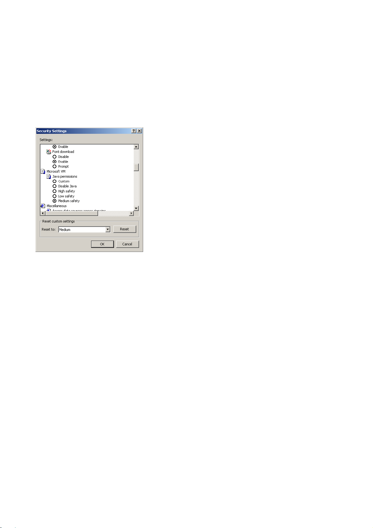
5. Check if the settings for the ActiveX controls and plug-ins are Enabled (see figures above):
− Download signed ActiveX controls has to be enabled.
− Download unsigned ActiveX controls has to be enabled.
− Initialize and script ActiveX controls not marked as safe .. has to be enabled.
− Run ActiveX controls and plug-ins has to be enabled.
− Script ActiveX controls marked as safe for scripting has to be enabled.
6. Scroll down and check if the Java permissions are set at Medium safety, see figure below.
7. Click the OK button. The Security tab appears.
8. Click the OK button.
BV Family R1.2 / Volume 1 (04.2) SM-SW 1 - 13
ALL RIGHTS RESERVED
© 2004 Koninklijke Philips Electronics N.V.
Page 17
Section 1 Service Manual BV Family R1.2
Software installation
5.3 I
A hardware key is required. Without a hardware key the access is restricted. The hardware key can only be
used for a limited period (one year). Upgrading is necessary after the one-year period has expired. Upgrading
can be done by the SSD/SSR service organization only.
For an initial installation of the hardware key software on the service PC refer to the Users Guide &
Installation Manual, which is supplied together with the HW-Key Toolbox.
5.4 C
The function of this short cut is to give quick access to a certain IP address with a certain port number.
First time use of BV-Scope
1. Connect a cable between the service PC and the MVS.
2. If PMSSec is active: in the Windows task bar right click the PMSSec icon (an icon with a horizontal key in
it). A menu appears. Click Close.
PMSSec must be closed otherwise, the file to be downloaded to the MVS will become unusable.
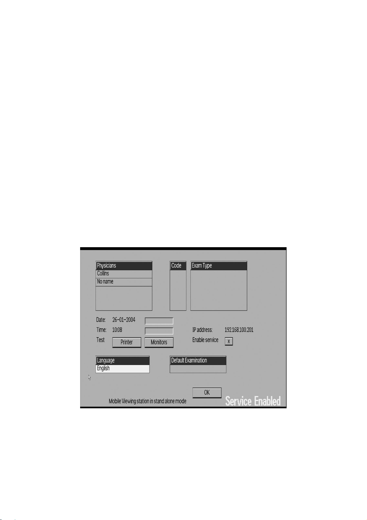
3. In the Setup panel of the MVS select Enable service. See figure below.
NSTALLATION OF THE
REATING A SHORT CUT FOR
BV-S
________________
COPE HARDWARE KEY
BV-S
COPE
WARNING
NOTE
If Enable service has not been selected in the Setup panel of the MVS, BV-Scope will not start and service is
not possible. This function has been added for security of patients’ data.
________________
SM-SW 1 - 14 (04.2) BV Family R1.2 / Volume 1
© 2004 Koninklijke Philips Electronics N.V.
ALL RIGHTS RESERVED
Page 18

Service Manual BV Family R1.2 Section 1
Software installation
4. Start Internet Explorer.
5. In the Address bar, enter: http:// followed by the IP address shown in the Setup panel of the MVS (the
default address is 192.168.1.61) followed by: :54670
6. The File Download window appears.
7. Click the Save button. The Save As window appears.
8. In the Save as field, select Desktop.
9. In the File name field change the name in: BV-Scope-DICOM.hta
10. Click the Save button. The Download Complete window appears.
11. Click Close.
12. Close Internet Explorer.
NOTE
The BV-Scope shortcut gives quick access to BV Family systems with a certain IP address and a certain port
number. For BV Family systems with another IP address and/or port number a new shortcut may be created.
________________
13. Start BV-Scope with the BV-Scope shortcut on the desktop. The Target Address Confirmation window
appears.
14. Enter the IP address shown in the Setup panel of the MVS.
15. Click the OK button. The PMS Security Reader window appears.
16. Enter your hardware key password.
17. Click the OK button. BV-Scope will appear with its top-level menu.
BV Family R1.2 / Volume 1 (04.2) SM-SW 1 - 15
ALL RIGHTS RESERVED
© 2004 Koninklijke Philips Electronics N.V.
Page 19
Section 1 Service Manual BV Family R1.2
Software installation
6 DOWNLOADING THE SYSTEM SOFTWARE TO THE BV FAMILY
SYSTEM
The system software for the BV Family system has to be downloaded from CD-Rom to the BV Family system
in case of a software update, a new release or reinstallation. The software can be downloaded in two ways:
• With an Ethernet connection (with a network cable or cross cable). This takes about 2 minutes.
• With a dial-up connection (serial cable). This takes about 20 minutes.
The two ways are described below. For a drawing of the connections, see SM-SW 1-3.
NOTE
On a BV Family system the system software has already been installed in the factory, for installation of a new
DFI-2 skip steps 2, 4 and 5.
________________
1. Turn on the MVS and wait until the system is operational.
2. In the Setup panel of the MVS: select enable service.
3. Connect a cable between the service PC and the BV Family System:
a cross cable or network cable to the Ethernet port of the BV Family System or
a serial cable to the D-connector of the BV Family System.
4. In BV-Scope select Install > Program Manual > Network Configuration.
5. Enable the Extended Service Access.
6. Put the CD into the CD-ROM drive of the service PC that has been connected to the system.
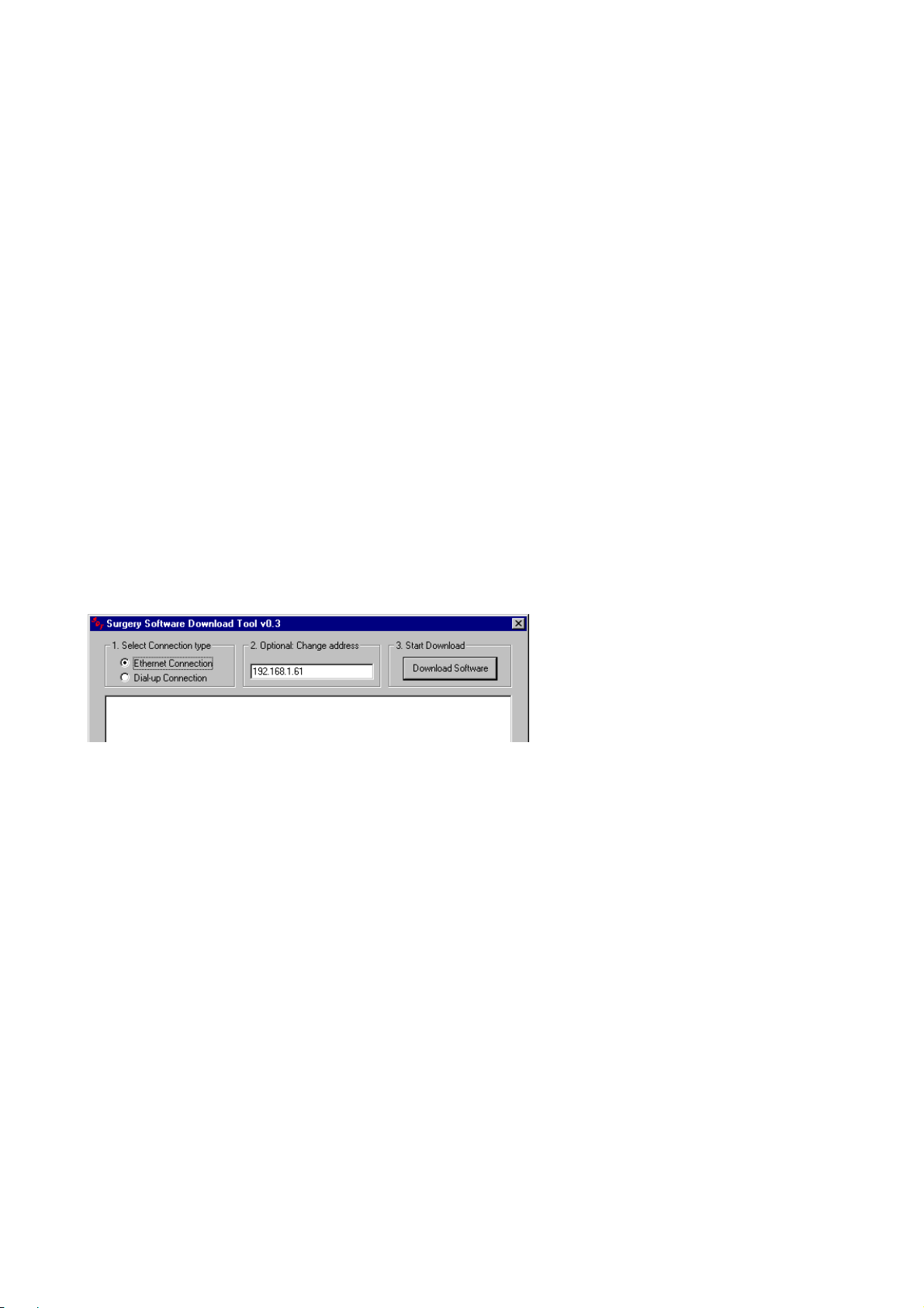
7. Start the SWDownload.exe application on the CD-ROM. The window below appears.
8. In case of connection with a cross cable or network cable: select Ethernet Connection.
In case of connection with a serial cable: select Dial-up Connection.
9. Enter the IP address shown on the Setup panel of the MVS.
10. Click the Download Software button. The software will be downloaded to the DFI and the result will be
displayed in the output window.
11. After about two minutes, the message Download completed successfully appears: close the window and
switch the BV Family system off and on.
12. Close all windows.
13. The DFI will download the software to the Midas board in the C-stand if the software version is newer. It
will display the download progress on the User Interface of the C-stand. In addition, the SHA1 LEDs will
flash. The MVS will display being in “stand-alone” mode.
14. Wait until download will be finished (progress is 100% will be visible on the User Interface on the C-
stand). The stand will reboot automatically.
15. After reboot, the complete system will be operational and standby.
SM-SW 1 - 16 (04.2) BV Family R1.2 / Volume 1
ALL RIGHTS RESERVED
© 2004 Koninklijke Philips Electronics N.V.
Page 20

Service Manual BV Family R1.2 Section 1
Software installation
7 PROCEDURES AFTER DFI REPLACEMENT OR SOFTWARE RE-
INSTALLATION
Actions required after replacements of the DFI or after re-installation of software.
1. Load software (see chapter 6)
2. Start BV-Scope.
3. Select Install > Program Automatic > Examination.
If you want to use the default examination types:
− On the BV Family System, select Intern.
− Click OK.
− Select a dataset valid for the system, see table below.
− Click the OK button.
If you want to use client specific examination types:
− On the Service PC, select Extern.
− Browse to the file Exam-cu.lib for a Libra system
Exam-cu.end for an Endura system
Exam-cu.pul for a Pulsera system
− Select the file and click the OK button.
− Click the OK button.
Table to select a dataset for a certain system
System
type
BV Libra Basic Standard / LCD 1 set Standard
BV Libra Basic High-End 1 set High-End
BV Libra Basic, Vasc Standard / LCD 2 sets Standard
BV Libra Basic, Vasc High-End 2 sets High-End
BV Endura Basic Standard / LCD 5 sets Standard
BV Endura Basic High-End 5 sets High-End
BV Endura Basic, Vasc Standard / LCD 8 sets Standard
BV Endura Basic, Vasc High-End 8 sets High-End
BV Endura Basic, Vasc, CO2 Standard / LCD 9 sets Standard
BV Endura Basic, Vasc, CO2 High-End 9 sets High-End
BV Pulsera Basic Standard / LCD 5 sets Vasc/CO2/Cardio Standard
BV Pulsera Basic High-End 5 sets Vasc/CO2/Cardio High-End
BV Pulsera Basic, Vasc Standard / LCD 8 sets Vasc/CO2/Cardio Standard
BV Pulsera Basic, Vasc High-End 8 sets Vasc/CO2/Cardio High-End
BV Pulsera Basic, Vasc, CO2. Standard / LCD 9 sets Vasc/CO2/Cardio Standard
BV Pulsera Basic, Vasc, CO2. High-End 9 sets Vasc/CO2/Cardio High-End
BV Pulsera Basic, Cardio Standard / LCD 8 sets Cardio/Vasc/CO2 Standard
BV Pulsera Basic, Cardio High-End 8 sets Cardio/Vasc/CO2 High-End
BV Pulsera Basic, Cardio, Vasc Standard / LCD 11 sets Cardio/Vasc/CO2 Standard
BV Pulsera Basic, Cardio, Vasc High-End 11 sets Cardio/Vasc/CO2 High-End
BV Pulsera Basic, Cardio, Vasc,
BV Pulsera Basic, Cardio, Vasc,
Commercial options Type of Monitor No of
Examinations
Standard / LCD 12 sets Vasc/CO2/Cardio Standard
CO2
High-End 12 sets Vasc/CO2/Cardio High-End
CO2
Dataset
(Exam file)
BV Family R1.2 / Volume 1 (04.2) SM-SW 1 - 17
ALL RIGHTS RESERVED
© 2004 Koninklijke Philips Electronics N.V.
Page 21

Section 1 Service Manual BV Family R1.2
Software installation
8 INSTALLATION OF EXTRA SOFTWARE OPTIONS
8.1 I
If a new SW license key has provided, follow the procedure below.
1. Select Install > Program Manual > System configuration.
2. In the SW license key field enter the new software string (provided by Philips).
3. In the Settings column, check the No. of examinations field (if applicable): for the required value see the
table above. Change the value if required.
4. Click the Apply button. A window appears. Read the text and continue accordingly.
5. Click the Info button. The installed options appear.
6. Check the installed options according to your software license key agreement.
7. Close the window.
8. Click the OK button in BV-Scope window.
9. Close BV-Scope.
10. Restart the system.
11. Check the new functions, see below.
8.2 C
NSTALLATION PROCEDURE
HECK OF NEW FUNCTIONS AFTER INSTALLATION OF EX TRA SOFTWARE OPTIONS
After installation of extra software options: perform the relevant checks on functions
Example for checks after installing the Vascular package
On the C-stand:
1. Choose Examination type.
2. Check if the examination types Vascular abdominal, Vascular Cerebral and Vascular Peripheral are
available.
3. Choose one of these 3 new examinations types.
4. Check the flip mode functions:
Is it possible to select Subtract, Roadmap or Trace (black) ?
− Choose Subtract.
− Check the functioning.
− Choose Trace (black)
− Check functioning.
− Check if Roadmap appears on the C-arc display and on the monitor.
− Check the Roadmap functions.
On the MVS:
1. Check on the monitor if the Pixel shift button and the Landmarking button can be used.
2. Use the buttons and check the functions.
Example for checks after installing of DICOM options
1. Perform network configuration.
2. Configure a printer or storage target.
3. Verify the DICOM export functions (in other words: check DICOM functions).
SM-SW 1 - 18 (04.2) BV Family R1.2 / Volume 1
ALL RIGHTS RESERVED
© 2004 Koninklijke Philips Electronics N.V.
Page 22

Service Manual BV Family R1.2 Section 2
Software functions
Section 2 BV-Scope menu items
Contents
1 TREE OF MENU & SUB MENU ITEMS..................................................................................................3
1.1 Authorization level required and user types ............................................................................................5
2 OVERVIEW OF MAIN SOFTWARE FUNCTIONS .................................................................................6
3 BUTTONS................................................................................................................................................6
4 SUB MENU ITEMS UNDER INSTALL....................................................................................................7
4.1 /Access Control/System Password Configuration ...................................................................................7
4.2 /Access Control/BV-Scope Password Configuration...............................................................................7
4.3 /Backup-Restore/ .....................................................................................................................................7
4.4 /Program Automatic/Configuration...........................................................................................................8
4.5 /Program Automatic/Examination ............................................................................................................8
4.6 /Program Automatic/DICOM Targets.......................................................................................................8
4.7 /Program Automatic/Printer types............................................................................................................8
4.8 /Program Manual/System Configuration/.................................................................................................9
4.9 /Program Manual/User Configuration/ ...................................................................................................10
4.10 /Program Manual/Network Configuration/..........................................................................................11
4.11 /Program Manual/Energy Storage/ ....................................................................................................12
4.12 /Program Manual/X-ray Tank/ ............................................................................................................12
4.13 /Program Manual/Examination Names/ .............................................................................................13
4.14 /Program Manual/Site Specific/..........................................................................................................13
4.15 /Program Manual/System Settings/....................................................................................................14
4.16 /Program Manual/Reset System Data ...............................................................................................16
4.16.1 /Program Manual/Reset System Data/Patient Image Database........................................................16
4.16.2 /Program Manual/Reset Data/Reset Calibration Data/ ......................................................................17
4.16.3 /Program Manual/Reset Data/Reset Examination Data/ ...................................................................17
4.17 /Program Manual/Demo Mode...........................................................................................................17
4.18 /Program Manual/DICOM Target Configuration.................................................................................17
4.18.1 /Program Manual/DICOM target Configuration/Export Targets.........................................................17
4.18.2 /Program Manual/DICOM Target Configuration/Printer Targets........................................................18
4.18.3 /Program Manual/DICOM Target Configuration/Worklist Query Definition........................................21
4.18.4 /Program Manual/DICOM Target Configuration/Worklist Management.............................................22
4.18.5 /Program Manual/DICOM Target Configuration/Modality Performed Procedure Step......................23
4.19 /Program Manual/DICOM Queue management.................................................................................23
4.20 /Adjustment ........................................................................................................................................24
4.21 /Performance Test..............................................................................................................................24
BV Family R1.2 / Volume 1 (05.0) SM-SW 2 - 1
ALL RIGHTS RESERVED
© 2005 Koninklijke Philips Electronics N.V.
Page 23

Section 2 Service Manual BV Family R1.2
Software functions
/Copy/Examination .............................................................................................................................24
4.22
4.23 /Copy/DICOM Targets........................................................................................................................24
5 SUB MENU ITEMS UNDER FAULTFIND.............................................................................................25
SM-SW 2 - 2 (05.0) BV Family R1.2 / Volume 1
ALL RIGHTS RESERVED
© 2005 Koninklijke Philips Electronics N.V.
Page 24

Service Manual BV Family R1.2 Section 2
Software functions
1 TREE OF MENU & SUB MENU ITEMS
Software tree of BV-Scope for Service users
INSTALL
ACCESS CONTROL
System Password Configuration
BV Scope Password Configuration
BACKUP/RESTORE
PROGRAM AUTOMATIC
Configuration
Examination
DICOM Targets
Printer types
PROGRAM MANUAL
System Configuration
User Configuration
Network Configuration
Energy Storage (RA only)
X-ray Tank
Examination Names (BV Endura and BV Pulsera only)
Site Specific
System Settings (with sub items)
Reset System Data (with sub items)
Demo Mode
DICOM target Configuration (with sub items)
DICOM queu management
ADJUSTMENT
X-ray tube
Fluoroscopy (FA only)
Conditioning
Filament
Dose output
Dose limitation
II/TV
FAULTFIND
LOGGING
Logfile Complete System
Energy Storage history (Ra only)
Tank history
System history and calibration
SERVICE UTILITIES
Retrieve error list
Retrieve DFI error list
Retrieve Suco error list
Mechanical
Basic lens focussing (12" only)
Optical camera focus
Centre of rotation
Centering image
Camera rotation
Electrical
Electrical II Focus
Video levels
Dose rate
Image Processor
Monitor image
Measure function
Collimator
Iris
Shutter A
Shutter B
Laser alignment
PERFORMANCE TEST
Image Quality
Level 1
Lower Level
Indicator / Buzzer
Key test
X-Ray tube performance
COPY
Examination
DICOM Targets
BV Family R1.2 / Volume 1 (05.0) SM-SW 2 - 3
ALL RIGHTS RESERVED
© 2005 Koninklijke Philips Electronics N.V.
Page 25
Section 2 Service Manual BV Family R1.2
Software functions
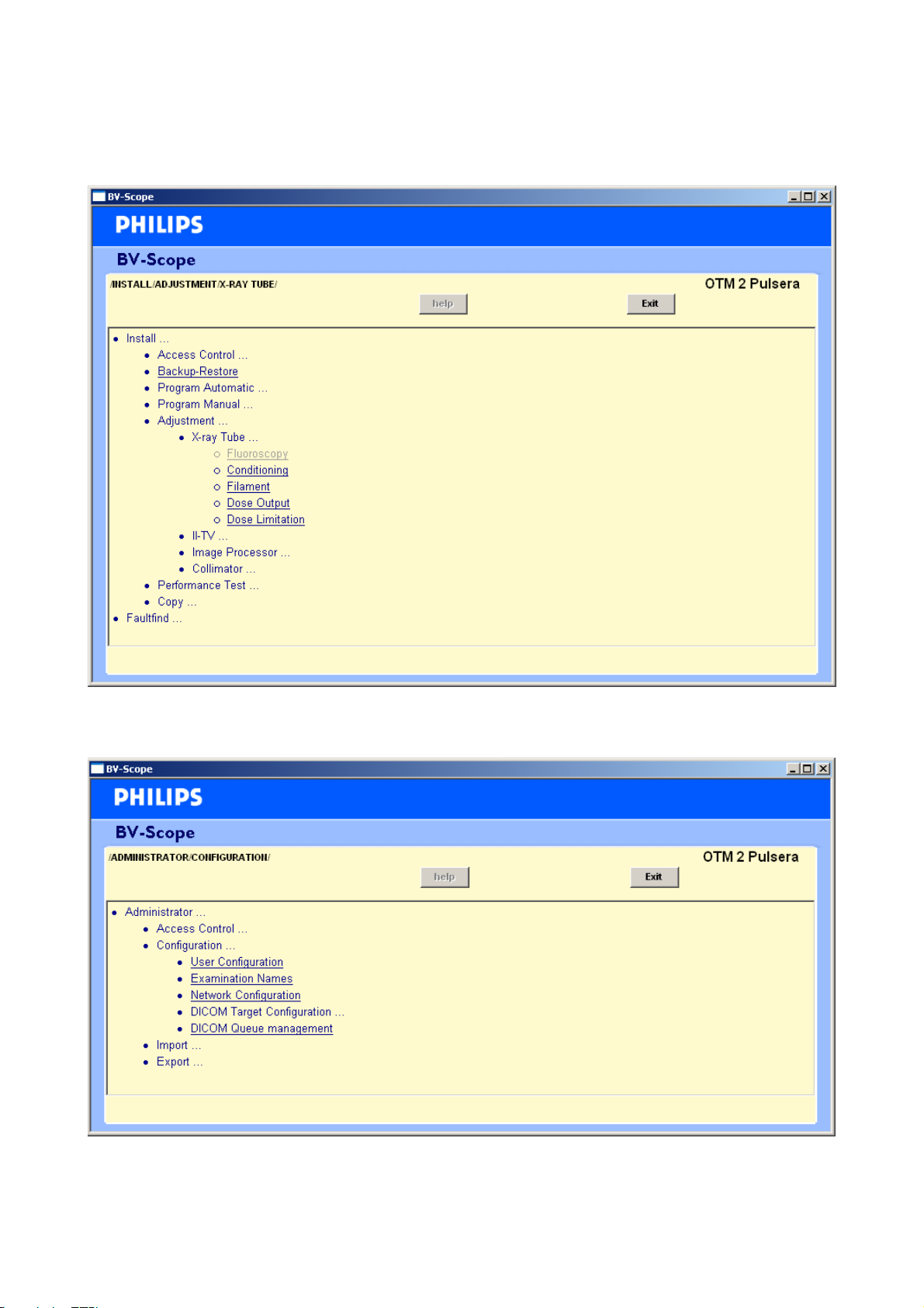
Example of a BV-Scope window for service users (authorization levels S0, S1, S2 and S3).
Remark: a grayed out item is not selectable.
Example of a BV-Scope window for BV-Scope administrators (authorization level A).
SM-SW 2 - 4 (05.0) BV Family R1.2 / Volume 1
ALL RIGHTS RESERVED
© 2005 Koninklijke Philips Electronics N.V.
Page 26
Service Manual BV Family R1.2 Section 2
Software functions
1.1 AUTHORIZATION LEVEL REQUIRED AND USER TYPES
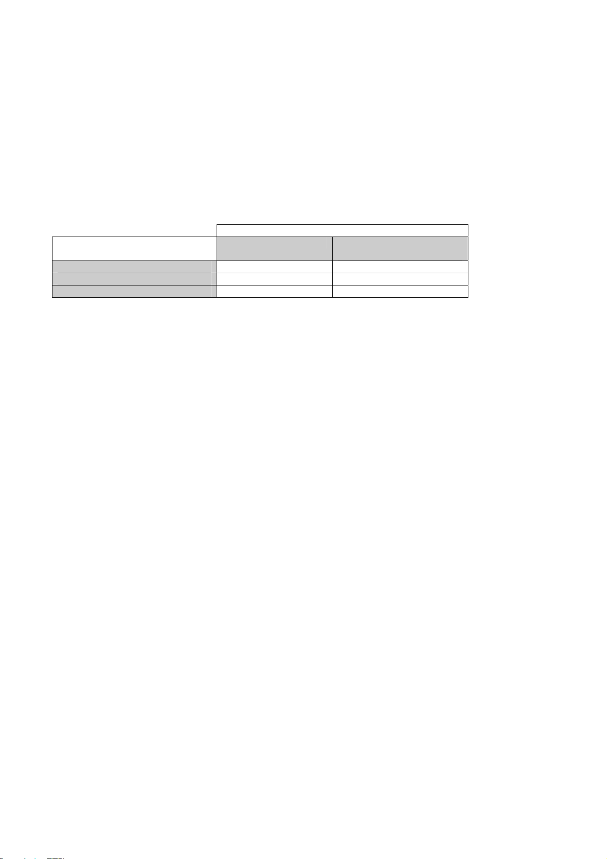
BV-Scope uses a hardware key (dongle) to protect serviceable functions. As applied within Surgery, it is only
allowed to be used by authorized users.
To be able to offer the relevant functionality to the categories of BV-Scope users, a protection mechanism is
defined which matches the possible protection levels. There are 3 levels of authorization, see table below.
Authorization level required and user types
Authorization level
User types (levels) Password required PMS sec & Dongle
required
BV-Scope Administrator (A)
BV-Scope Service (S0, S1, S2)
BV-Scope Factory (S3)
*) This password can be configured by user types with the levels S0, S1, S2 or S3).
In this definition, level S3 means the highest access rights. In practice, this means that these procedures are
allowed to be used by the smallest category of users (e.g. high level specialists). In special occasions, it can
be useful to make use of authorization level S3: contact the helpdesk.
The BV-Scope administrator (level A), has the lowest access rights. The BV-Scope administrator does not
require a hardware key, but has restricted access.
For all user types, only the permitted procedures are visible.
(The information above is a copy of the information in SM-G section 2.)
X*
Dongle level 0, 1 or 2
Dongle level 3
BV Family R1.2 / Volume 1 (05.0) SM-SW 2 - 5
ALL RIGHTS RESERVED
© 2005 Koninklijke Philips Electronics N.V.
Page 27
Section 2 Service Manual BV Family R1.2
Software functions
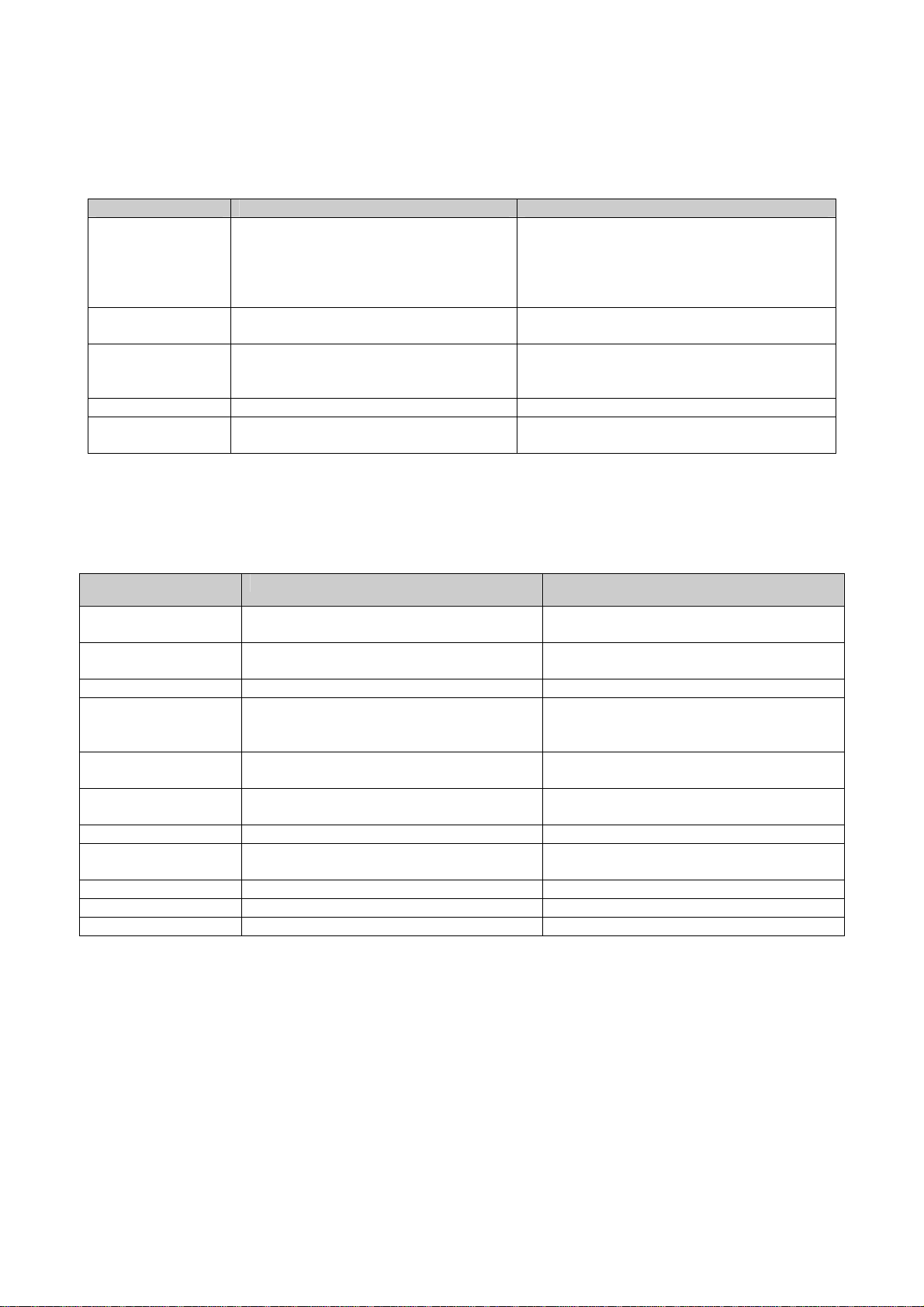
2 OVERVIEW OF MAIN SOFTWARE FUNCTIONS
What to do Menu item Intended use
Install the system
Customizing
Maintenance
IQ performance
Access Control
Install > Backup - Restore
Install > Program Automatic
Install > Program Manual
Install > Adjustment
Install > Copy
Install > Program Manual
Install > Adjustment
Install > Performance Test
Install > Adjustment
Faultfind > Logging
Install > Performance Test
Install > Access Control
Connecting two subsystems
Loading Config. Data, Exam. Data.
Customizing the system
Adjustment and verification of the system
Backup Exam.
Customizing the System data
Adjustment and verification of the system
Checking the system
Adjustment and verification of the system
Faultfinding
Checking the performance of the system
Changing the system and BV-Scope
password
3 BUTTONS
The following buttons are used in BV-Scope:
Button Function
next Go to next screen without storage of
values
previous Go to previous screen without storage of
values
repeat Repeat current step of adjustment
ok Store values and go to next screen Note: read the instruction window in BV–
Scope for the correct functioning of the
OK button.
apply Store values Note: clicking the apply button is ignored
during radiation
cancel Go to main BV-scope menu without apply
of values of current step
help Go to help info
info Displays info about software packages
installed
save Save current page
exit Exit BV-Scope application
check Test values
SM-SW 2 - 6 (05.0) BV Family R1.2 / Volume 1
ALL RIGHTS RESERVED
© 2005 Koninklijke Philips Electronics N.V.
Page 28

Service Manual BV Family R1.2 Section 2
Software functions
4 SUB MENU ITEMS UNDER INSTALL
For the default settings of values, see the relevant Release Bulletins.
4.1 /ACCESS CONTROL/SYSTEM PASSWORD CONFIGURATION
This menu item is optional. Your current software version may not contain this option.
Settings (authorization level required ≥ A)
Configuration item Value set Default Explanation
Password string n.a. Password of the user of the system
4.2 /ACCESS CONTROL/BV-SCOPE PASSWORD CONFIGURATION
Settings (authorization level required ≥ A)
Configuration item Value set Default Explanation
Administrator name string n.a. Name of the administrator of the system
Password string n.a. Password of the administrator of the system
4.3 /BACKUP-RESTORE/
Reference
Configuration item Value set Explanation
System Serial Number xxx Serial no. of the system filled by the factory
Settings (authorization level required ≥ S2)
Configuration item Value set Explanation
Action No action
Reconnect
Service connection
Mobile Viewing Station serial
number
X-ray Control serial number Enter text string Serial number of X-ray Control (on the C-arm
Enter text string Serial number of Mobile Viewing Station
Used after replacement of Midas or DFI.
Used to make a test connection for faultfinding
purposes between two usually not connected
subsystems (MVS and CAS)
Stand)
BV Family R1.2 / Volume 1 (05.0) SM-SW 2 - 7
ALL RIGHTS RESERVED
© 2005 Koninklijke Philips Electronics N.V.
Page 29

Section 2 Service Manual BV Family R1.2
Software functions
4.4 /PROGRAM AUTOMATIC/CONFIGURATION
Settings (authorization level required ≥ S3)
Configuration item Value set Explanation
Configuration File
File
Intern (BV Family system)
Extern (Service PC)
File name
Select Intern to load the Configuration File from the
internal disk to the system.
Select Extern to load the Configuration File from the
diskette of the Service PC to the system.
In the File field, the name of a Configuration File has
to be entered. With the Browse button, this file can
also be selected.
4.5 /PROGRAM AUTOMATIC/EXAMINATION
Settings (authorization level required ≥ S0)
Configuration item Value set Explanation
Select Examination File Intern (BV Family system)
Extern (Service PC)
Select Intern to load the default examination data.
Select Extern to load the examination data from the
Service PC to the system.
4.6 /PROGRAM AUTOMATIC/DICOM TARGETS
(Authorization level required ≥ A)
In the File field, the name of the data file of a DICOM Target has to be entered. With the Browse button, this
file can also be selected. With this function, a back up of the DICOM configuration made with the function
‘Install/Copy/DICOM Targets’ can be restored.
4.7 /PROGRAM AUTOMATIC/PRINTER TYPES
(Authorization level required ≥ A)
In the File field, the name of pre-configures Printer Types file has to be entered. With the Browse button, this
file can also be selected. The Printer Types File (Dicom.ptf) can be found on the BV Family Software cd-rom,
in the subdirectory: dfi\data.
SM-SW 2 - 8 (05.0) BV Family R1.2 / Volume 1
ALL RIGHTS RESERVED
© 2005 Koninklijke Philips Electronics N.V.
Page 30

Service Manual BV Family R1.2 Section 2
Software functions
4.8 /PROGRAM MANUAL/SYSTEM CONFIGURATION/
Reference
Configuration item Value set Explanation
System type: BV Endura-9”, BV Endura-12”
BV Pulsera-9”, BV Pulsera-12”
BV Libra-6”, BV Libra-9”
X-ray Tank installed dd-mmm-yyyy Installation date of the X-ray Tank
Battery pack installed dd-mmm-yyyy Installation date of the Energy Storage Unit
SW release SW version number
Hospital Name Read from setting Name set in the setting window
Host Identification Read from setting 8-digit Identification number
Video Frequency [Hz] 50 This setting cannot be changed. The setting is
Settings (authorization level required ≥ S2)
Configuration item Value set Explanation
System Serial number text string Serial number of the system
Shutter L + R Coupled Yes, No Coupling of movements of the shutters
Set upon user's preference
Auto Shutter Positioning Enable, Disable Enable or disabled the automatic positioning of the shutters
of the collimator.
Camera angle [deg] 0 .. 359 Default position of the camera angle.
Set upon user's preference
Radiography possible Yes, No If Yes has been selected: radiography and fluoroscopy are
possible.
Warning: Radiography with 6" BV Libra is not permitted
in the USA.
If No has been selected: only fluoroscopy is possible.
Selection depends on mains supply conditions and/or legal
requirements.
No. of examinations
types
1 - 13 Maximum number of examinations depending on system
type and options. To display the options use the info button
in the upper frame of the window.
Max kV [kV] 40…max kV Maximum voltage of the X-ray tube
Depends on legal requirements
French Homologation Yes, No French Homologation can only be selected on FA systems.
Depends on legal requirements
Caution: after French Homologation has been enabled, it
must be calibrated with Filament (tube) adjustment.
Gamma Correction 1…4 Always select “1”
Initialize Image Disk Yes, No All images are removed if Yes is selected; no other data is
removed. Selection of Yes is necessary when the max
number of images to be stored is changed.
SW License key Text string License string.
Type of BV Family system
independent of the mains frequency (50/60 Hz).
BV Family R1.2 / Volume 1 (05.0) SM-SW 2 - 9
ALL RIGHTS RESERVED
© 2005 Koninklijke Philips Electronics N.V.
Page 31

Section 2 Service Manual BV Family R1.2
Software functions
4.9 /PROGRAM MANUAL/USER CONFIGURATION/
Reference
Configuration item Value set Explanation
SW release SW version number
Host Identification Read from setting 8-digit Identification number
Settings (authorization level required ≥ A)
Configuration item Value set Explanation
Hospital name Text string
Language English, French,
German, Spanish,
Swedish
Birth date field as Birth date, Remark Field can be set for fixed date format or as free remark
Data Format dd-mm-yyyy,
yyyy-mm-dd,
mm-dd-yyyy
Live additional text On, Off Hospital name, name of physician, examination type,
Display Exam type Yes, No
Units of measure 0.1 mm, 0.01 inch Measure function in inch or mm
Set upon user's preference
Default language of the User Interface on the stand and the
Mobile Viewing Station.
Set upon user's preference
Set upon user's preference
Date format
Set upon user's preference
examination date and time Yes/No visible during live fluoro
Set upon user's preference
Set upon user's preference
Set upon user's preference
SM-SW 2 - 10 (05.0) BV Family R1.2 / Volume 1
ALL RIGHTS RESERVED
© 2005 Koninklijke Philips Electronics N.V.
Page 32
Service Manual BV Family R1.2 Section 2
Software functions
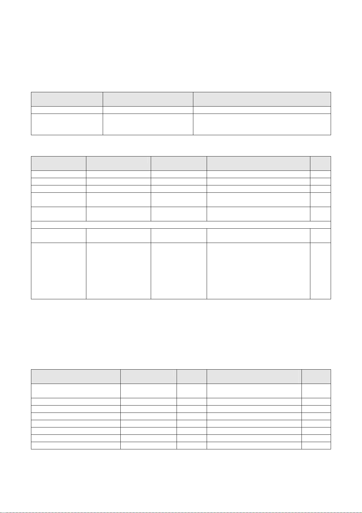
4.10 /PROGRAM MANUAL/NETWORK CONFIGURATION/
Reference
Configuration item Value Explanation
SW Release RR.VV.LL Release number. Version number. Level number.
Ethernet address XX.XX.XX.XX.XX.XX Unique ID no. of the network card of the BV Fam.
System.
Also called MAC address
Settings
Configuration
item
IP address ###.###.###.### Read from setting IP address of BV Family system ≥ A
Subnet mask ###.###.###.### Read from setting Subnet mask of BV Family system ≥ A
Default Gateway ###.###.###.### Read from setting Gateway used by BV Fam. system ≥ A
Extended Service
Access
Station name 20 characters, alpha-
DICOM Configuration
AE Title 20 characters, alpha-
Interpolation On, Off On If images are not square and targets
The BV Family uses port 8104 for DICOM Storage Commit and port 104 for all other DICOM AEs.
Remark: the parameters below can be used by the IT specialist of the hospital network to optimize the system
and/or network load and the target performance.
Configuration item Value set/range Default Explanation
Maximum Protocol Data Units
(PDU) Size
Receive message Timeout 1…3600 sec 60 ≥ A
Association close timeout 1…3600 sec 1 ≥ A
Association reply timeout 1…3600 sec 60 ≥ A
Association release timeout 1…3600 sec 60 ≥ A
Write timeout 1…3600 sec 120 ≥ A
Network Connect Timeout 1…3600 sec 60 ≥ A
Network Inactivity –Timeout 1…3600 sec 60 ≥ A
Value set/range Default Explanation Auth
level
Checkbox (Enabled,
Disabled)
numeric
numeric
Disabled Enables access.
Required for software download.
“No name” DICOM station name of the BV
Family system
“No name” DICOM Application Entity title of the
BV Family system
≥ S2
≥ A
≥ A
≥ A
cannot handle this, it is needed to
export images with interpolation on.
Interpolation determines the aspect
ratio of the pixels of the image.
Interpolation On: aspect ratio: 1 : 1
Interpolation Off:
aspect ratio: 549 : 753
NOTE
________________
Auth.
level
4….256 kB 28 ≥ A
BV Family R1.2 / Volume 1 (05.0) SM-SW 2 - 11
ALL RIGHTS RESERVED
© 2005 Koninklijke Philips Electronics N.V.
Page 33

Section 2 Service Manual BV Family R1.2
Software functions
Digital Navigation Link Option
Configuration item Value set/range Default Explanation
Port number 1025 - 65555 55555 Port number of the digital navigation
≥ A
link port.
Change the port number in case it is
requested by the FSE from the
company that delivers the
navigational tool.
4.11 /PROGRAM MANUAL/ENERGY STORAGE/
Reference
Configuration item Value set Explanation
Prev. installation: Date Previous installation date of battery-pack
Settings (authorization level required ≥ S2)
Configuration item Value set Explanation
Install new Battery-pack Yes, No Selection of Yes will store the current date in the
field 'Battery-pack installed' under /Program
Manual/System Configuration
4.12 /PROGRAM MANUAL/X-RAY TANK/
Reference
Configuration item Value set Explanation
Prev. installation Date Previous installation date of X-ray tank
Settings (authorization level required ≥ S2)
Configuration item Value set Explanation
Install new tank Yes, No Selection of Yes will store the current date in the
field 'X-ray tank installed' under /Program
Manual/System Configuration
SM-SW 2 - 12 (05.0) BV Family R1.2 / Volume 1
ALL RIGHTS RESERVED
© 2005 Koninklijke Philips Electronics N.V.
Page 34
Service Manual BV Family R1.2 Section 2
Software functions
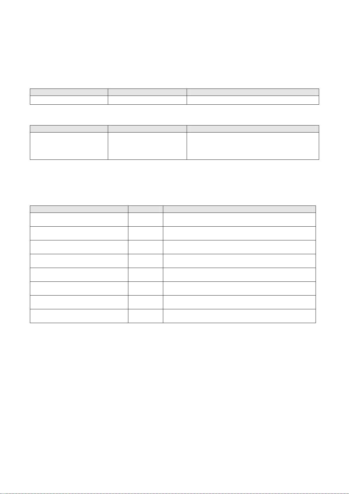
4.13 /PROGRAM MANUAL/EXAMINATION NAMES/
Reference
Configuration item Value set Explanation
Last Exam. update Date Date of the last examination update
Settings (authorization level required ≥ A)
Configuration item Value set Explanation
XX Examination name
06 - etc.
'Name of examination' The examination names 01 up to 05 are
predefined, cannot be changed and are not
visible. The examination name will be used on
the user interface of the stand.
4.14 /PROGRAM MANUAL/SITE SPECIFIC/
Settings (authorization level required ≥ S0)
Configuration item Value set Explanation
Initialize Image Disk Yes, No In this screen, select Yes when you have changed the
run buffer. Caution: all images will be lost.
Run Buffer Size 10…5000 Gives the amount of images that is always left free for
storing runs.
Cocktail [1] Contrast* 50 .. 150 Default value = 115 %
Can eventually be set
Cocktail [2] Contrast* 50 .. 150 Default value = 130 %
Can eventually be set
Cocktail [3] Contrast* 50 .. 150 Default value = 150 %
Can eventually be set
Cocktail [1] Brightness* 50 .. 150 Default value = 104 %
Can eventually be set
Cocktail [2] Brightness* 50 .. 150 Default value = 109 %
Can eventually be set
Cocktail [3] Brightness* 50 .. 150 Default value = 113 %
Can eventually be set
*) Setting of a cocktail of the Contrast/Brightness keys on the stand and the Mobile Viewing Station.
BV Family R1.2 / Volume 1 (05.0) SM-SW 2 - 13
ALL RIGHTS RESERVED
© 2005 Koninklijke Philips Electronics N.V.
Page 35
Section 2 Service Manual BV Family R1.2
Software functions
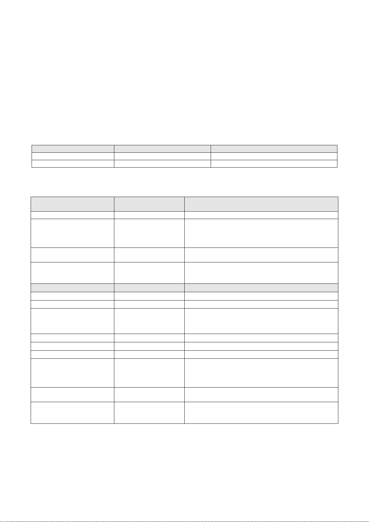
4.15 /PROGRAM MANUAL/SYSTEM SETTINGS/
The following predefined system settings can be chosen:
• Examination type
• X-mode
• Flip-mode
• NR-level (BV Libra only)
These predefined settings can be modified with the settings mentioned below.
Reference
Configuration item Value set Explanation
Actual Examination Name of the actual examination.
Last Examination update Date Date of last change of settings.
Settings (authorization level required ≥ S0)
(to make changes to the predefined settings above)
Configuration item Value set Explanation
Common:
kV/mA curve Normal, High Contrast,
Focus Small, Large Select small or large X-ray focus. The X modes
XTV Measure Field Size 0 = auto, 1 ... 7 Relative field size, fixed size 20% up to 70% or
Left button
Image processing:
Enable subtraction Yes, No Enables / disables subtraction parameters
Trace black/white Black, White Depends on the commercial option, trace white (CO2)
Landmarking level 0 ... 3 Default landmark level during subtraction
Noise reduction level 1 … 6 Default noise reduction level number (Libra only)
Image storage:
Storage Rate [fr/s] 0, 1, 2, 3, 5, 8, 12, 25 Default setting of image store rate, 0, 1, 2, 3, 5, 8, 12,
Store Last Image Hold Yes, No If enabled, Last Image Hold will be stored
VCR Control On, Off Automatic switch on the video cassette recorder or
High contrast and Isowatt kV/mA curve are selections
Isowatt
for Pulsera only. Caution: For the HQ Ortho and
Thorax Examination changing kV/mA curve can
result in unexpected kV stabilized values.
Pulsed and Digital can only be used with a large focus
automatic mode.
Leave in automatic mode (only 20% is feasible)
or trace black. Depends on used contrast medium (For
iodine select Black, for CO2 select White)
25 depending on disk capacity. In case of pulsed
exposure, the frame rate is equal to the pulse rate.
Set upon user's preference
Set upon user's preference
Medical DVD-Recorder: yes or no.
Set upon user's preference
SM-SW 2 - 14 (05.0) BV Family R1.2 / Volume 1
ALL RIGHTS RESERVED
© 2005 Koninklijke Philips Electronics N.V.
Page 36

Service Manual BV Family R1.2 Section 2
Software functions
Video processing:
Integration factor 0 .. 60 Required number of image frames in order to achieve
a desired noise reduction level. Change the value
only after consulting an application specialist
FM Noise Reduction Level
(FM = Fluoro Mode)
1, ¾, ½, ¼, 1/8, 1/16 K-factor, specifies the level of noise reduction to be
applied during fluoroscopy. Change the value only
after consulting an application specialist
FM Movement Detection On, Off Movement switches back Noise reduction per pixel or
when movement is detected during fluoroscopy
FM Movement Sensitivity Off, low, medium, high
Do not change this value
FM Contrast -49 … + 49 Default position of Contrast ruler in Mobile Viewing
Station Post proc screen during fluoroscopy
FM Brightness -49 … + 49 Default position of Brightness ruler in MVS Post proc
screen during fluoroscopy
FM Edge Enhancement Off, 1 .. 15 Default position of Edge ruler in MVS Post proc
screen during fluoroscopy
FM Video Invert On, Off Default 'position' of Invert button on MVS user
interface during fluoroscopy
SM Noise Reduction Level
(SM = Subtraction Mode)
1, ¾, ½, ¼, 1/8, 1/16 K-factor, specifies the level of noise reduction to be
applied during subtraction. Change the value only
after consulting an application specialist
SM Movement Detection On, Off Movement switches Noise reduction locally or when
movement is detected during subtraction
SM Movement Sensitivity Off, low, medium, high
Do not change this value
SM Contrast -49 … + 49 Default position of Contrast ruler in MVS Post proc
screen during subtraction
SM Brightness -49 … + 49 Default position of Brightness ruler in MVS Post proc
screen during subtraction
SM Edge Enhancement off, 1 - 15 Default position of Edge ruler in MVS Post proc
screen during subtraction
SM Video Invert On, Off Default 'position' of Invert button on MVS user
interface during subtraction
Right button
X-ray generator
Pulse width Short, Medium, Long Duration of the pulse (Pulsera only)
Initial pulse rate 3, 5, 8, 12, 25 Initial pulse rate in frames/sec (Pulsera only)
Image processing:
Enable subtraction Yes, No Enable or disable the subtraction function
Trace black/white Black, White Depends on the commercial option, trace white (CO2)
or trace black. Depends on used contrast medium (For
iodine select Black, for CO2 select White)
Landmarking level 0 .. 3 Default landmark level during subtraction.
BV Family R1.2 / Volume 1 (05.0) SM-SW 2 - 15
ALL RIGHTS RESERVED
© 2005 Koninklijke Philips Electronics N.V.
Page 37

Section 2 Service Manual BV Family R1.2
Software functions
Image storage:
Storage Rate [fr/s] 0, 1, 2, 3, 5, 8, 12, 25 Default setting of image store rate, 0, 1, 2, 3, 5, 8, 12,
25 depending on disk capacity. In case of pulsed
exposure, the frame rate is equal to the pulse rate.
Set upon user's preference
Store Last Image Hold Yes, No If enabled, Last Image Hold will be stored
Set upon user's preference
VCR Control On, Off Automatic switch on the videocassette recorder: Off or
On. Set upon user's preference
Video processing:
Integration factor 0 … 60 Required number of image frames in order to achieve
a desired noise reduction level
FM Noise Reduction Level 1, ¾, ½, ¼, 1/8, 1/16 K-factor, specifies the level of noise reduction to be
applied during fluoroscopy
FM Movement Detection On, Off Movement switches back Noise reduction per pixel or
when movement is detected during fluoroscopy
FM Movement Sensitivity Off, low, medium, high
Do not change this value
FM Contrast -49 … + 49 Default position of Contrast ruler in MVS Post proc
screen during fluoroscopy
FM Brightness -49 … + 49 Default position of Brightness ruler in MVS Post proc
screen during fluoroscopy
FM Edge Enhancement off, 1 - 15 Default position of Edge ruler in MVS Post proc
screen during fluoroscopy
FM Video Invert On, Off Default 'position' of Invert button on MVS user
interface during fluoroscopy
SM Noise Reduction Level 1, ¾, ½, ¼, 1/8, 1/16 K-factor, specifies the level of noise reduction to be
applied during subtraction
SM Movement Detection On, Off Movement switches Noise reduction locally or when
movement is detected during subtraction
SM Movement Sensitivity off, low, medium, high
Do not change this value
SM Contrast -49 … + 49 Default position of Contrast ruler in MVS Post proc
screen during subtraction
SM Brightness -49 … + 49 Default position of Brightness ruler in MVS Post proc
screen during subtraction
SM Edge Enhancement off, 1 - 15 Default position of Edge ruler in MVS Post proc
screen during subtraction
SM Video Invert On, Off Default 'position' of Invert button on MVS user
interface during subtraction
4.16 /PROGRAM MANUAL/RESET SYSTEM DATA
4.16.1 /Program Manual/Reset System Data/Patient Image Database
Settings (authorization level required ≥ S2)
Configuration item Value set Explanation
Reset Patient Image Database Yes, No Caution: if set to Yes, all images and patient
data will be lost.
SM-SW 2 - 16 (05.0) BV Family R1.2 / Volume 1
ALL RIGHTS RESERVED
© 2005 Koninklijke Philips Electronics N.V.
Page 38

Service Manual BV Family R1.2 Section 2
Software functions
4.16.2 /Program Manual/Reset Data/Reset Calibration Data/
Settings (authorization level required ≥ S2)
Configuration item Value set Explanation
Reset calibration data Yes, No Caution: if set to Yes, the system will delete all
calibration data and will start up with default
values
4.16.3 /Program Manual/Reset Data/Reset Examination Data/
Settings (authorization level required ≥ S2)
Configuration item Value set Explanation
Reset examination data Yes, No Caution: if set to Yes, all examination names
and adapted system settings will be lost.
4.17 /PROGRAM MANUAL/DEMO MODE
Settings (authorization level required ≥ S2)
Configuration item Value set Explanation
Demo mode No Action,
activated,
deactivated
The High Voltage cables must be disconnected to make the demo mode single fault safe.
Select Activated for operating the system without radiation, for
example to give demos on exhibitions.
Select Deactivated for operating the system with radiation.
Select No Action to leave the demo mode unchanged.
CAUTION
________________
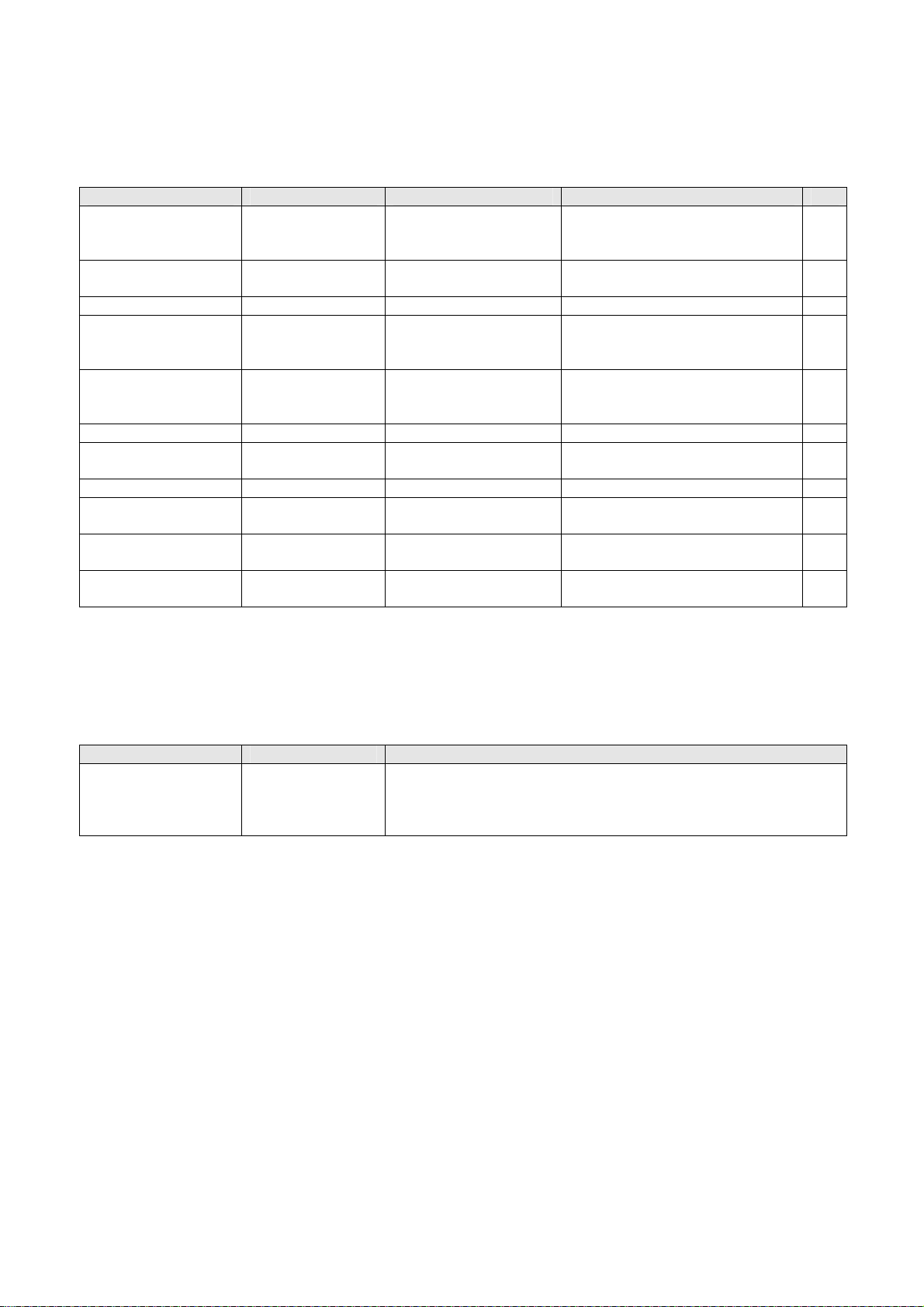
4.18 /PROGRAM MANUAL/DICOM TARGET CONFIGURATION
4.18.1 /Program Manual/DICOM target Configuration/Export Targets
Reference (authorization level required ≥ A)
Configuration item Value set Explanation
Export Target No Name,
already configured
Export Targets
The names that can be selected depend on the already
configured Export Targets.
(via Program Manual/ DICOM target Configuration/Export
Targets)
BV Family R1.2 / Volume 1 (05.0) SM-SW 2 - 17
ALL RIGHTS RESERVED
© 2005 Koninklijke Philips Electronics N.V.
Page 39
Section 2 Service Manual BV Family R1.2
Software functions
Settings (authorization level required ≥ A)
Configuration item Value set Default Explanation
Name Text string “No Name“ User defined name of export
≥ A
target (appears in the DFI export
panel (MVS)).
Type None,
Store
None To remove a target
To create a target
≥ A
Order in list Read current value Number of export target ≥ A
Enable Yes, No No Checkbox. If enabled then the
≥ A
target appears in the DFI export
panel (MVS).
AE Title 16 characters,
alpha-numeric
“No name” Name of Application Entity. The
name must correspond with the
≥ A
AE Title of the target.
IP address ###.###.###.### 0.0.0.0 IP address of export target. ≥ A
Port number 5 numeric
104 Port number of export target. ≥ A
characters
Storage Commit* Disabled, Enabled Disabled Enables Storage Commit options ≥ A
SC AE Title* 20 characters,
“No name” AE title Storage Commit target ≥ A
alpha-numeric
SC IP address* ###.###.###.### 0.0.0.0 IP address Storage Commit
≥ A
target
SC Port Number* 5 characters,
numeric
104 Port number Storage Commit
target
≥ A
*) Only for systems with Extended DICOM option.
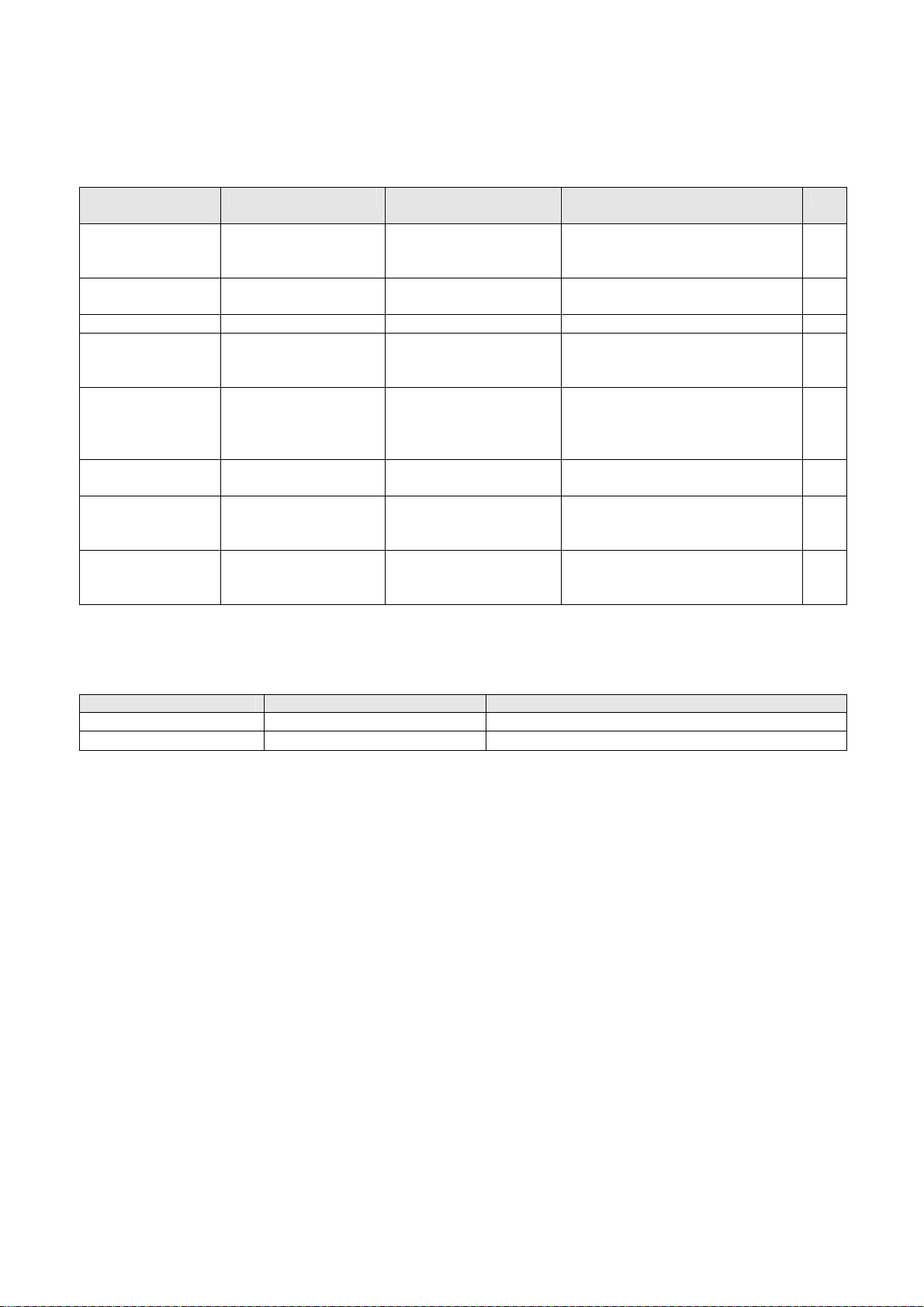
4.18.2 /Program Manual/DICOM Target Configuration/Printer Targets
Reference
Configuration item Value set Explanation
Printer Target No Name,
etc.
The names that can be selected depend on the already
configured Printer Target.
(via Program Manual/DICOM target Configuration/Printer
Targets)
SM-SW 2 - 18 (05.0) BV Family R1.2 / Volume 1
ALL RIGHTS RESERVED
© 2005 Koninklijke Philips Electronics N.V.
Page 40
Service Manual BV Family R1.2 Section 2
Software functions
Settings (authorization level required ≥ A)
Configuration
Value set Default Explanation
item
Name Text string “No name” User defined name of printer
≥ A
target (appears in the DFI export
panel (MVS).
Type None,
Export
None To remove a target
To create a target
≥ A
Order in list Read current value Number of print target ≥ A
Enable Yes, No No Checkbox. If enabled then the
≥ A
target appears in the DFI export
panel (MVS).
AE Title No Name,
etc.
“No name” Name of Application Entity. The
name must correspond with the
≥ A
AE Title of the target. Refer to
the manual of the target.
IP address ###.###.###.### 0.0.0.0 IP address of target. Refer to the
≥ A
manual of the printer.
Port number 104 Port number of printer target.
≥ A
Refer to the manual of the
printer.
Printer Type Printer Type names None Names of printer types in the
≥ A
Printer Types File.
After clicking the Next button the following window appears.
Reference
Configuration item Value set Explanation
Selected Printer Target: 25 characters, alpha-numeric n.a.
Selected Printer Type: 15 characters, alpha-numeric n.a.
For settings, see next page.
BV Family R1.2 / Volume 1 (05.0) SM-SW 2 - 19
ALL RIGHTS RESERVED
© 2005 Koninklijke Philips Electronics N.V.
Page 41

Section 2 Service Manual BV Family R1.2
Software functions
Settings
Configuration item Value set Explanation Auth.
Level
Print_Priority LOW, MED, HIGH, DEFAULT Priority in print queue.
≥ A
May be fixed or
selectable.
Film_Destination CURRENT,
PROCESSOR,
Possible selections can
differ per printer.
≥ A
MAGAZINE,
BIN,
DEFAULT
Film_Destination Bin
number
Array[1..25] of Integer Bin no. (if BIN has been
selected under
≥ A
Film_Destination)
Film_Orientation PORTRAIT, LANDSCAPE ≥ A
Film_Size CURRENT, 8INX10IN ,
8_5INX11IN, 10INX12IN,
10INX14IN, 11INX11IN,
Possible selections can
differ per printer.
≥ A
11INX14IN, 11INX17IN,
14INX14IN, 14INX17IN,
24CMX24CM, 24CMX30CM,
A4, A3,
DEFAULT
Medium_Type CURRENT, BLUE FILM,
CLEAR FILM, PAPER,
Possible media types can
differ per printer.
≥ A
TRANSPARENCY, DEFAULT
Border Density BLACK, WHITE, OD, DEFAULT ≥ A
Border Density Value 1…1000, DEFAULT Level of density of border.
≥ A
(If OD has been selected
under Border Density).
Number of Copies Integer (1-99), DEFAULT Limitation to 9 is most
≥ A
safe.
Magnification Type REPLICATE, BILINEAR,
≥ S2
CUBIC, NONE, DEFAULT
Smoothing Type 0, 1, 10, 11, 12, 13, 14, 140, 15,
2, 3, 4, 5, 6, 7, 8, 9,
This value can differ for
each printer or interface.
≥ S2
ENHANCED, ENHANCED1,
MEDIUM, NORMAL, SHARP,
SMOOTH
Minimum Density 0…1000, DEFAULT Minimum density level. ≥ S2
Maximum Density 0…1000, DEFAULT Maximum density level. ≥ S2
Empty Image Density BLACK, WHITE Density of empty image. ≥ S2
Polarity NORMAL, REVERSE,
≥ S2
DEFAULT
Trim YES, NO, DEFAULT Depends on the
≥ S2
application.
Image Display
Format Supported
(this item is not
visible in BV-Scope)
Rowsxcolumns (e.g. “1x1”,
“2x2”, “3x2”)
This value depends on the
number of images per film
that the user selects.
(Some printers can use
≥ S2
custom formats).
Configuration
Information
Character string (max 40
characters), DEFAULT
Defines gamma correction
on the printer for an image
≥ S2
SM-SW 2 - 20 (05.0) BV Family R1.2 / Volume 1
ALL RIGHTS RESERVED
© 2005 Koninklijke Philips Electronics N.V.
Page 42

Service Manual BV Family R1.2 Section 2
Software functions
4.18.3 /Program Manual/DICOM Target Configuration/Worklist Query
Definition
This menu item is optional. Only for systems with Extended DICOM option.
Reference (authorization level required ≥ S2)
Configuration item Value set Explanation
List of already
configured queries
Settings (authorization level required ≥ S2)
Parameter Value range Default Explanation
Query Name 20 characters, alpha-
Enable Checkbox (Yes, No) No
Modality Enable/Disable +
Scheduled Station
AE Title
Scheduled Station
Name
Scheduled Procedure
Step
start date
User defined query name Name of query
“No Name” User defined query name (appears in the
numeric
BV-Scope Worklist Management Server
Configuration window)
OT Enables the BV Family system to query
OT | XA | RF
the Worklist Server for entries with the
selected Modality type.
Enable/Disable Enable Enables the BV Family system to query
the Worklist Server for entries with the
Scheduled Station AE Title of the BV
Family system.
Enable/Disable Enables the BV Family system to query
the Worklist Server for entries with the
Scheduled Station Name of the BV
Family system.
Enable/Disable +
Today
Yesterday, today and
tomorrow
Today Enables the BV Family system to query
the Worklist Server for entries with the
selected Scheduled Procedure Step start
date.
1 Week range centered
around today
2 Week range centered
around today
BV Family R1.2 / Volume 1 (05.0) SM-SW 2 - 21
ALL RIGHTS RESERVED
© 2005 Koninklijke Philips Electronics N.V.
Page 43

Section 2 Service Manual BV Family R1.2
Software functions
4.18.4 /Program Manual/DICOM Target Configuration/Worklist Management
This menu item is optional. Only for systems with Extended DICOM option.
Reference (authorization level required ≥ A)
Configuration item Value set Explanation
WLM target User defined target name Name of target
Settings (authorization level required ≥ A)
Parameter Value range Default Explanation
Name 20 characters, alpha-numeric “No name” Name of Worklist Server
Enable Checkbox (Yes, No) No Enabling of the Worklist Server
AE Title 20 characters, alpha-numeric “No name” Name of Application Entity. The name
must correspond with the AE Title of the
Worklist Server.
IP address ###.###.###.### 0.0.0.0 IP address of WLS.
Port number Max. 5 characters, numeric 104 Port number of WLS.
Timeout Max. 6 characters, numeric Max. response time for query
Query List of configured queries Queries as defined with the menu item
Worklist Query Definition (see above).
SM-SW 2 - 22 (05.0) BV Family R1.2 / Volume 1
ALL RIGHTS RESERVED
© 2005 Koninklijke Philips Electronics N.V.
Page 44

Service Manual BV Family R1.2 Section 2
Software functions
4.18.5 /Program Manual/DICOM Target Configuration/Modality Performed
Procedure Step
This menu item is optional. Only for systems with extended DICOM option.
Reference (authorization level required ≥ A)
Configuration item Value set Explanation
MPPS target User defined name Name of MPPS target
Settings (authorization level required ≥ A)
Parameter Value range Default Explanation
Name 20 characters, alpha-numeric “No name” Name of MPPS server.
Enable Checkbox (Yes, No) No Enabling of MPPS.
AE title 20 characters, alpha-numeric “No name” Name of Application
Entity. The name must
correspond with the AE
Title of the MPPS server.
Refer to the manual of the
MPPS server.
IP address ###.###.###.### 0.0.0.0 IP number of MPPS.
Refer to the manual of the
MPPS.
Port number Max. 5 characters, numeric 104 Port number of MPPS.
Refer to the manual of the
MPPS.
4.19 /PROGRAM MANUAL/DICOM QUEUE MANAGEMENT
Reference
Configuration item Value set Explanation
List with queue entries:
• Target Name
• Type
• Patient Name
• Status
BV Family R1.2 / Volume 1 (05.0) SM-SW 2 - 23
ALL RIGHTS RESERVED
25 characters, alpha-numeric
Export | Print | MPPS
20 characters, alpha-numeric
Queued | Failed | Waiting for Storage Commit
© 2005 Koninklijke Philips Electronics N.V.
List of not completed
print or export jobs.
Page 45
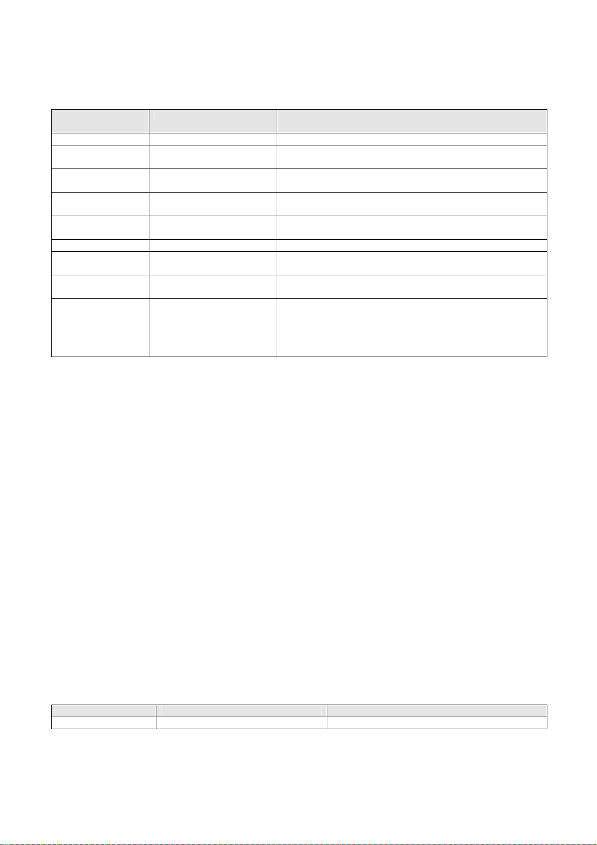
Section 2 Service Manual BV Family R1.2
Software functions
Settings (authorization level required ≥ A)
Configuration
item
Target Name Text string* Target Name of the selected entry in the Reference panel.
Target Type EXPORT | PRINT |
Patient Name 20 characters, alpha-
Accession Number 16 characters, numeric* Accession Number of the selected entry in the Reference
Number of Images Integer* Number of Images of the selected entry in the Reference
Image Format XA|SC|SC with text* Image Format of the selected entry in the Reference panel.
Page Format Columns x Rows –
Detailed Status Detailed status
Delete Entry Checkbox (Yes, No) To delete the entry selected in the Reference panel.
Resend Entry Checkbox (Yes, No)
*) These values cannot be set in this window.
Value set Explanation
Target Type of the selected entry in the Reference panel.
MPPS*
Patient name of the selected entry in the Reference panel.
numeric*
panel.
panel.
Page Format of the selected entry in the Reference panel.
number of images/page*
Detailed Status of the selected entry in the Reference
description*
panel.
If selected Yes, the entry will be deleted from the
transfer queue.
If selected Yes, the entry will be resent after clicking
the Resume button in the Export panel on the MVS.
4.20 /ADJUSTMENT
For the submenu items under Adjustment, see SM-CM 5 Adjustment & verification.
4.21 /PERFORMANCE TEST
(Authorization level required ≥ S0)
For the submenu items under Performance Test, see SM-CM 5 Adjustment & verification.
4.22 /COPY/EXAMINATION
(Authorization level required ≥ S0)
This function is used to make a Back-up from the user defined Examination data (System Settings).
This back up can be restored after re-installation of software.
Click ok to start the copy function. Follow the instructions on the screen.
4.23 /COPY/DICOM TARGETS
(Authorization level required ≥ A)
This function is used to make a Back-up of the DICOM export targets.
This back up can be restored after re-installation of software.
Click ok to start the copy function. Follow the instructions on the screen.
Settings (authorization level required ≥ A)
Configuration item Value set Explanation
Output file: dicom.tdf Name of output file
SM-SW 2 - 24 (05.0) BV Family R1.2 / Volume 1
ALL RIGHTS RESERVED
© 2005 Koninklijke Philips Electronics N.V.
Page 46

Service Manual BV Family R1.2 Section 2
Software functions
5 SUB MENU ITEMS UNDER FAULTFIND
(Authorization level required ≥ S0)
These items are self-explaining and therefore will not be explained here.
BV Family R1.2 / Volume 1 (05.0) SM-SW 2 - 25
ALL RIGHTS RESERVED
© 2005 Koninklijke Philips Electronics N.V.
Page 47

Service Manual BV Family R1.2 Section 3
DICOM configuration
Section 3 DICOM Configuration
Contents
INTRODUCTION .....................................................................................................................................3
1
1.1 DICOM and network devices...................................................................................................................3
1.2 Background information on the DICOM standard....................................................................................4
1.2.1 The DICOM standard ...........................................................................................................................4
1.2.2 Scope and field of application ..............................................................................................................5
1.2.3 Definitions.............................................................................................................................................5
1.2.4 Goals of the DICOM standard..............................................................................................................6
2 BV-SCOPE ACCESS CONFIGURATION ..............................................................................................8
2.1 Configuration of a system password........................................................................................................8
2.2 Creation of an administrator’s account ....................................................................................................8
3 NETWORK CONFIGURATION...............................................................................................................9
3.1 Introduction ..............................................................................................................................................9
3.2 Preconditions ...........................................................................................................................................9
3.3 Actions & checks......................................................................................................................................9
3.4 Configuration of a digital navigation link ................................................................................................11
4 CONFIGURATION OF DICOM STORAGE (EXPORT) TARGETS......................................................12
4.1 Introduction ............................................................................................................................................12
4.2 Preconditions .........................................................................................................................................12
4.3 Actions & checks....................................................................................................................................13
5 LOADING OF PRINTER TYPES FILE..................................................................................................14
5.1 Introduction ............................................................................................................................................14
5.2 Precondition...........................................................................................................................................14
5.3 Actions & checks....................................................................................................................................14
6 CONFIGURATION OF DICOM PRINT TARGETS ...............................................................................15
6.1 Introduction ............................................................................................................................................15
6.2 Preconditions .........................................................................................................................................15
6.3 Actions & checks....................................................................................................................................16
BV Family R1.2 / Volume 1 (04.1) SM-SW 3 - 1
ALL RIGHTS RESERVED
© 2004 Koninklijke Philips Electronics N.V.
Page 48

Section 3 Service Manual BV Family R1.2
DICOM configuration
CONFIGURATION OF DICOM WORKLIST MANAGEMENT..............................................................17
7
7.1 Worklist query definition.........................................................................................................................17
7.1.1 Introduction.........................................................................................................................................17
7.1.2 Preconditions......................................................................................................................................17
7.1.3 Actions & checks ................................................................................................................................17
7.2 Worklist management server.................................................................................................................19
7.2.1 Introduction.........................................................................................................................................19
7.2.2 Preconditions......................................................................................................................................19
7.2.3 Actions & checks ................................................................................................................................20
7.3 Modality Performed Procedure Step .....................................................................................................21
7.3.1 Introduction.........................................................................................................................................21
7.3.2 Preconditions......................................................................................................................................21
7.3.3 Actions & checks ................................................................................................................................22
8 DICOM QUEUE MANAGEMENT..........................................................................................................23
8.1 Introduction ............................................................................................................................................23
8.2 Actions & checks....................................................................................................................................23
8.2.1 To delete queue entries .....................................................................................................................23
8.2.2 To resend queue entries ....................................................................................................................23
9 FAULT FINDING ...................................................................................................................................24
9.1 Association Close Timeout ....................................................................................................................24
9.2 Configuration problems (BV-Scope on Service PC)..............................................................................24
9.3 Usage problems (MVS) .........................................................................................................................25
9.3.1 Transfer of images to Storage/Print target fails .................................................................................25
9.3.2 Printed images are not as expected ..................................................................................................25
9.3.3 Queue problems.................................................................................................................................26
SM-SW 3 - 2 (04.1) BV Family R1.2 / Volume 1
ALL RIGHTS RESERVED
© 2004 Koninklijke Philips Electronics N.V.
Page 49

Service Manual BV Family R1.2 Section 3
DICOM configuration
1 INTRODUCTION
1.1 DICOM AND NETWORK DEVICES
This sections deals with DICOM configuration in case of BV-Scope with integrated DICOM functions
(= performing DICOM functions without external Merge Box.).
DICOM (Digital COmmunication in Medicine) is a protocol for communication between medical devices.
The DFI of a Libra, Endura or Pulsera communicates via DICOM with the network of a hospital. The DFI
sends images acquired with a Libra, Endura or Pulsera together with information of patients, acquisition data
etc. to a network target.
Devices also on this network can be:
• printers
• archives to archive images en data, for example PACS
• workstations for analyzing of images
• WLM servers (Worklist Management), for planning of examinations of patients
• MPPS (Modality Performed Procedure Step), to report the status of performed examinations
• a service PC for configuration of the devices connected to the network
With certain functions of the user interface of the BV-family, the images and data on the DFI can be sent to
the above-mentioned devices on the network. All functions are optional.
The functions are:
• Export
• Print
• WLM
• MPPS
• Storage Commitment
See the user manual of the BV-family for more information on these functions.
Relation between devices and functions.
Device
Printers Archives Workstations WLM
servers
Function
Export
Print
WLM
MPPS
Storage
x x
x
x
x
x x
Commitment
In DICOM terms, the BV-Family system is called the modality. Printers, archives, workstations, WLM/MPPS
servers are called targets.
What happens when a patient who has to be examinated enters a hospital?
1. The data of a patient will be entered in a Hospital Information System (HIS) or a Radiology Information
System (RIS). In case of an emergency, this step can be omitted.
2. On a WLM Server, the examinations a patient has to follow have to be scheduled.
3. When a certain examination has been performed, the status will be reported to an MPPS.
4. The data and images of each examination can be printed, stored or sent to a workstation.
MPPS
BV Family R1.2 / Volume 1 (04.1) SM-SW 3 - 3
ALL RIGHTS RESERVED
© 2004 Koninklijke Philips Electronics N.V.
Page 50

Section 3 Service Manual BV Family R1.2
DICOM configuration
5. Images that are manipulated on a workstation can eventually be printed and/or be stored from the
workstation.
6. To be sure images are stored safely a storage commitment procedure is used. Images that are sent from
a modality to the storage device are only deleted on the modality if the storage device gives commitment.
This commitment will only be given if the images are stored safely on the storage device.
This section describes the order for configuration of the BV Family System for DICOM networking.
Described are:
• System configuration: configuration of the DICOM settings of the BV Family System.
• Configuration of DICOM Storage targets: steps needed to add DICOM Storage (export) targets (the
targets can be the devices mentioned in the table above).
• Loading of pre-configured printer types: required before adding DICOM Print targets.
• Configuration of DICOM Print targets: steps needed to add DICOM Print targets.
This section assumes the user is familiar with:
• Basic TCP/IP networking concepts, such as:
IP address, TCP port, subnet, gateway.
• Basic DICOM concepts, such as:
DICOM AE Title, Service Class Provider, Service Class User. For definitions, refer to p. 5.
Abbreviation Explanation
CT Computed Tomography
DICOM Digital Imaging and COmmunication in Medicine
HIS Hospital Information System
PACS Picture Archiving and Communication System
SC Secondary Capture
RIS Radiology Information System
TCP/IP Transmission Control Protocol/Internet Protocol
WLM WorkList Management
XA X-ray Angiographic
1.2 BACKGROUND INFORMATION ON THE DICOM STANDARD
For configuration of the BV Family System, it is not necessary to read this chapter.
1.2.1 The DICOM standard
The DICOM Standard, which is currently designated Digital Imaging and Communications in Medicine
(DICOM), embodies a number of major enhancements to previous versions of the ACR-NEMA Standard:
1. It is applicable to a networked environment. The ACR-NEMA Standard was applicable in a point-to-point
environment only; for operation in a networked environment, a Network Interface Unit (NIU) was required.
DICOM supports operation in a networked environment using the industry standard networking protocol
TCP/IP.
2. It is applicable to an off-line media environment. The ACR-NEMA Standard did not specify a file format or
choice of physical media or logical file system. DICOM supports operation in an offline media environment
using industry standard media such as CD-R and MOD and logical file systems such as ISO 9660 and PC
File System (FAT16).
3. It specifies how devices claiming conformance to the Standard react to commands and data being
exchanged. The ACR-NEMA Standard was confined to the transfer of data, but DICOM specifies, through
the concept of Service Classes, the semantics of commands and associated data.
4. It specifies levels of conformance. The ACR-NEMA Standard specified a minimum level of conformance.
DICOM explicitly describes how an implementer must structure a Conformance Statement to select
specific options.
SM-SW 3 - 4 (04.1) BV Family R1.2 / Volume 1
ALL RIGHTS RESERVED
© 2004 Koninklijke Philips Electronics N.V.
Page 51

Service Manual BV Family R1.2 Section 3
DICOM configuration
5. It is structured as a multi-part document. This facilitates evolution of the Standard in a rapidly evolving
environment by simplifying the addition of new features. ISO directives which define how to structure
multi-part documents have been followed in the construction of the DICOM Standard.
6. It introduces explicit Information Objects not only for images and graphics but also for waveforms, reports,
printing, etc.
7. It specifies an established technique for uniquely identifying any Information Object. This facilitates
unambiguous definitions of relationships between Information Objects as they are acted upon across the
network.
The DICOM Standard is an evolving standard and it is maintained in accordance with the Procedures of
the DICOM Standards Committee. Proposals for enhancements are forthcoming from the DICOM
Committee member organizations based on input from users of the Standard. These proposals are
considered for inclusion in future editions of the Standard. A requirement in updating the Standard is to
maintain effective compatibility with previous editions.
1.2.2 Scope and field of application
The DICOM Standard facilitates interoperability of medical imaging equipment by specifying:
• For network communications, a set of protocols to be followed by devices claiming conformance to the
Standard.
• The syntax and semantics of Commands and associated information, which can be exchanged using
these protocols.
• For media communication, a set of media storage services to be followed by devices claiming
conformance to the Standard, as well as a File Format and a medical directory structure to facilitate
access to the images and related information stored on interchange media.
• Information that must be supplied with an implementation for which conformance to the Standard is
claimed.
The DICOM Standard does not specify:
• The implementation details of any features of the Standard on a device-claiming conformance.
• The overall set of features and functions to be expected from a system implemented by integrating a
group of devices each claiming DICOM conformance.
• A testing/validation procedure to assess an implementation's conformance to the Standard.
The DICOM Standard pertains to the field of Medical Informatics. Within that field, it addresses the
exchange of digital information between medical imaging equipment and other systems. Because such
equipment may interoperate with other medical devices, the scope of this Standard needs to overlap with
other areas of medical informatics. However, the DICOM Standard does not address the breadth of this field.
1.2.3 Definitions
Attribute: A property of an Information Object. An Attribute has a name and a value, which are independent
of any encoding scheme
Command: A request to operate on information across a network.
Command Element: An encoding of a parameter of a command, which conveys this parameter's value.
Command Stream: The result of encoding a set of DICOM Command Elements using the DICOM encoding
scheme.
Conformance Statement: A formal statement that describes a specific product implementation that uses the
DICOM Standard. It specifies the Service Classes, Information Objects, and Communication Protocols
supported by the implementation.
Data Dictionary: A registry of DICOM Data Elements, which assigns a unique tag, a name, value
characteristics, and semantics to each Data Element.
Data Element: A unit of information as defined by a single entry in the data dictionary.
Data Set: Exchanged information consisting of a structured set of Attributes. The value of each Attribute
in a Data Set is expressed as a Data Element.
BV Family R1.2 / Volume 1 (04.1) SM-SW 3 - 5
ALL RIGHTS RESERVED
© 2004 Koninklijke Philips Electronics N.V.
Page 52

Section 3 Service Manual BV Family R1.2
DICOM configuration
Data Stream: The result of encoding a Data Set using the DICOM encoding scheme (Data Element
Numbers and representations as specified by the Data Dictionary).
DICOM AE Title: Name of the Application Entity.
Information Object: An abstraction of a real information entity (e.g., CT Image, Structured Report, etc.) that is
acted upon by one or more DICOM Commands.
Note: It is an informal term corresponding to Information Object Definition.
Information Object Class: A formal description of an Information Object, which includes a description of its
purpose and the Attributes it possesses. It does not include values for these attributes.
Note: It is an informal term corresponding to Service-Object Pair Class, more commonly as a SOP Class.
Information Object Instance: A representation of an occurrence of a real-world entity, which includes values
for the Attributes of the Information Object Class to which the entity belongs.
Note: It is an informal term corresponding to a Service-Object Pair Instance, more commonly as a SOP
Instance.
Message: A data unit of the Message Exchange Protocol exchanged between two cooperating DICOM
Applications. A Message is composed of a Command Stream followed by an optional Data Stream.
Service Class: A structured description of a service, which is supported by cooperating DICOM
Applications using specific DICOM Commands acting on a specific class of Information Object.
Service Class Provider: Application Entity that provides the Service Class.
Service Class User: Application Entity that uses the Service Class.
1.2.4 Goals of the DICOM standard
The DICOM Standard facilitates interoperability of devices claiming conformance. In particular, it:
• addresses the semantics of Commands and associated data. For devices to interact, there must be
standards on how devices are expected to react to Commands and associated data, not just the
information which is to be moved between devices;
• addresses the semantics of file services, file formats and information directories necessary for off-line
communication;
• is explicit in defining the conformance requirements of implementations of the Standard. In particular, a
conformance statement must specify enough information to determine the functions for which
interoperability can be expected with another device claiming conformance.
• facilitates operation in a networked environment.
• is structured to accommodate the introduction of new services, thus facilitating support for future medical
imaging applications.
• makes use of existing international standards wherever applicable, and it conforms to established
documentation guidelines for international standards.
Even though the DICOM Standard has the potential to facilitate implementations of PACS solutions, use
of the Standard alone does not guarantee that all the goals of a PACS will be met. This Standard
facilitates interoperability of systems claiming conformance in a multi-vendor environment, but does not,
by itself, guarantee interoperability.
This Standard has been developed with an emphasis on diagnostic medical imaging as practiced in
radiology, cardiology and related disciplines; however, it is also applicable to a wide range of image and
non-image related information exchanged in clinical and other medical environments.
SM-SW 3 - 6 (04.1) BV Family R1.2 / Volume 1
ALL RIGHTS RESERVED
© 2004 Koninklijke Philips Electronics N.V.
Page 53
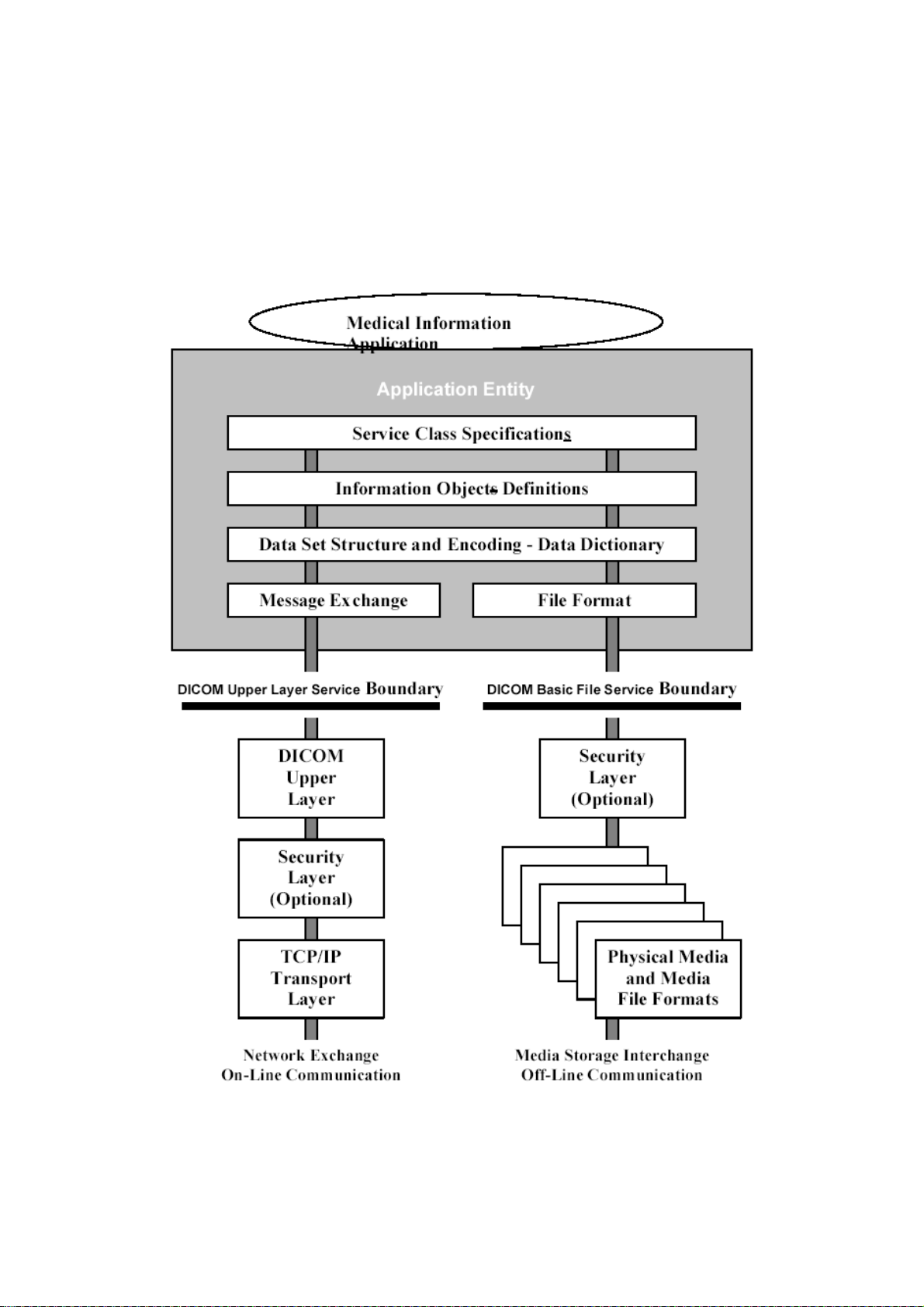
Service Manual BV Family R1.2 Section 3
DICOM configuration
The figure below presents the general communication model of the Standard, which spans both network
(online) and media storage interchange (off-line) communication. Applications may relay on either one of the
following boundaries:
• The Upper Layer Service, which provides independence from specific physical networking
communication support and protocols such as TCP/IP.
• The Basic DICOM File Service, which provides access to Storage Media independently from specific
media storage formats and file structures.
General communication model of the DICOM standard
BV Family R1.2 / Volume 1 (04.1) SM-SW 3 - 7
ALL RIGHTS RESERVED
© 2004 Koninklijke Philips Electronics N.V.
Page 54

Section 3 Service Manual BV Family R1.2
DICOM configuration
2 BV-SCOPE ACCESS CONFIGURATION
2.1 CONFIGURATION OF A SYSTEM PASSWORD
A system password has to prevent unauthorized persons to have access to the patient administration of the
BV Family system. The possibility to configure a system password is an option. The system password is
also referred to as the DFI password.
Procedure to configure a system password
1. Open BV-Scope (Double click the BV-Scope icon on the desktop).
2. Select: Install > Access control > System Password Configuration
3. DFI password, select: Enabled.
4. In the New DFI Password field, enter new password (6-20 characters).
5. In the Confirm DFI Password field, enter new password again.
6. Click ok to activate the changes.
NOTE
If the password has been lost, contact a BV-scope administrator or Philips service engineer to create a new
password.
________________
2.2 CREATION OF AN ADMINISTRATOR’S ACCOUNT
Access to BV-Scope is possible in two ways:
1. With a BV-Scope administrator’s account and a password.
2. With a Service PC, PMSSec and a hardware key.
Procedure to create an administrator’s account:
1. Open BV-Scope (Double click the BV-Scope icon on the desktop).
2. Select: Install > Access control > BV-Scope Password Configuration
3. In the BV-Scope Administration account field, enter a user name
4. In the 2 other fields enter the same password.
5. Click ok.
NOTE
If the password for the BV-Scope Administrator has been lost, a Philips service engineer can create a new
Administrator’s account.
________________
SM-SW 3 - 8 (04.1) BV Family R1.2 / Volume 1
ALL RIGHTS RESERVED
© 2004 Koninklijke Philips Electronics N.V.
Page 55
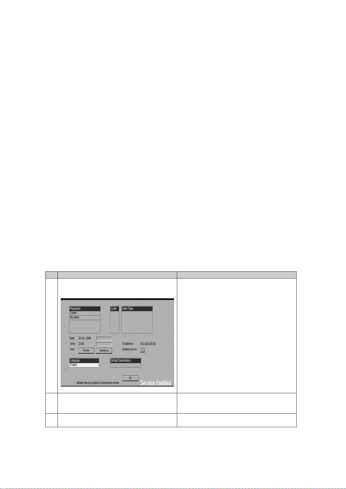
Service Manual BV Family R1.2 Section 3
DICOM configuration
3 NETWORK CONFIGURATION
3.1 INTRODUCTION
NOTE
The procedures in this section have to be proceeded by the ones in SM-SW section 1.
________________
Before the BV Family System can be used in a DICOM network, the BV Family System itself has to be
configured by the steps indicated below.
3.2 PRECONDITIONS
The following information is required before the BV Family System can be configured:
• IP address of the system (to be obtained from the network administrator).
• Subnet mask to be used (to be obtained from the network administrator).
• Default gateway to be used when accessing targets outside the subnet (if applicable to be obtained from
the network administrator).
• Station name to be used for the system (to be obtained from the network administrator).
• DICOM AE Title to be used for the system (to be obtained from the network administrator).
• A user name and a password are necessary for configuration without a hardware key, so for BV-Scope
administrators (see procedure below).
3.3 ACTIONS & CHECKS
Action Check / Remarks
1. On the MVS, select Enable service
(see figure below).
2. Open BV-scope
(Double click the BV-scope icon on the
desktop.)
3. Select: Install > Program Manual > Network
Configuration
Enable service can be selected in the Setup
panel of the MVS. The Setup panel can be
reached by clicking the corresponding icon
in the Patient administration screen
A connection to the MVS will be made.
Note: Administrator rights for Windows are
required for some of the following actions.
BV Family R1.2 / Volume 1 (04.1) SM-SW 3 - 9
ALL RIGHTS RESERVED
© 2004 Koninklijke Philips Electronics N.V.
Page 56

Section 3 Service Manual BV Family R1.2
DICOM configuration
4. In the Network configuration part of the
Settings panel enter:
• IP address
• Subnet mask
• Default gateway
5. In the DICOM configuration part of the
Settings panel enter:
• Station Name
• AE Title
When no default gateway will be used (all
targets on the same subnet) the default
gateway should have a value of: “0.0.0.0”
The AE Title is case sensitive.
6. Interpolation: select On Interpolation determines the aspect ratio of
the pixels of the image.
Interpolation On: aspect ratio: 1 : 1
Interpolation Off: aspect ratio: 549 : 753
7. Do not change the default Maximum PDU
Size or Timeout values
For the default values, refer to SM-SW
section 2 chapter 4.10. These settings can
be used by the hospital IT specialist to
optimize the network performance.
8. Click the OK button
9. Physically connect the BV Family System to
the network
10. Restart the BV Family System
11.
Remark:
When the IP address of the BV-System has been changed, the connection between the
Service PC and the BV Family System will be lost. From the Service PC the BV Family
System must be reconnected using the new IP address. Follow the procedure below.
12. Double click the My Computer icon.
13. If the service PC and the BV Family system have been connected with a serial cable,
continue with item 16.
14. For the Service PC enter an IP address
within the same subnet as the IP address of
For procedure, refer to SM-SW section 1
chapter 4.2
the BV Family System.
15. For the IP address in step 14: enter this
address as a trusted site.
For procedure, refer to SM-SW section 1
chapter 5.1
16. Restart BV-Scope.
17. When the Target address Confirmation
window appears: enter the IP address
configured in step 4.
NOTE
After restart of the BV-System, to make service possible always go to the Setup panel of the MVS and select
Enable service (The Setup panel can be reached by clicking the corresponding icon in the Patient
administration screen). In the lower right corner on the MVS screen (left monitor) the text Service Enabled (or
a translation of this text) appears.
A PMS security hardware key level 2 (for X-ray) is required to service the system.
________________
SM-SW 3 - 10 (04.1) BV Family R1.2 / Volume 1
ALL RIGHTS RESERVED
© 2004 Koninklijke Philips Electronics N.V.
Page 57

Service Manual BV Family R1.2 Section 3
DICOM configuration
3.4 CONFIGURATION OF A DIGITAL NAVIGATION LINK
A navigation device can be connected to the BV Family system. A navigation device optimizes fluoro
navigation. The Last Image Hold is transferred automatically over the Ethernet line.
Procedure to configure the digital navigation link.
1. Open BV-Scope.
2. Select: Install > Program Manual > Network Configuration
3. In the settings panel under Digital Link configuration enter the port number of the navigation
device.
4. Click ok to activate the changes.
BV Family R1.2 / Volume 1 (04.1) SM-SW 3 - 11
ALL RIGHTS RESERVED
© 2004 Koninklijke Philips Electronics N.V.
Page 58

Section 3 Service Manual BV Family R1.2
DICOM configuration
4 CONFIGURATION OF DICOM STORAGE (EXPORT) TARGETS
4.1 INTRODUCTION
If the BV Family System has been configured according to the previous chapter, the procedure described
below can be followed. On the BV Family System a maximum number of 25 Storage and/or Print targets can
be configured. Before a target can be selected in the Export Panel on the MVS’ user interface, it needs to be
configured via BV-Scope. This chapter describes the addition of a Storage (export) target. For a print target
refer to chapter 5.
4.2 PRECONDITIONS
The following information is required before a DICOM Storage target can be configured:
• DICOM AE Title of the storage target
(to be obtained from the network administrator)
• IP address of the storage target
(to be obtained from the network administrator)
• Port number used for DICOM storage on the storage target
(to be obtained from the network administrator)
Before the configuration of a DICOM Storage target, make sure:
• If your target device is on the list of devices tested by Philips, refer to the PMS MIT Interoperability
Intranet site.
If your target device is NOT on the list of devices tested by Philips:
The Conformance Statement of the DICOM Print target indicates the support of:
Service Class Provider for Basic Grayscale Print SOP Class.
In case of doubt, contact the X-Ray help desk.
• If your target device is NOT on the list of devices tested by Philips:
The Conformance Statements of the DICOM Storage target and that of the BV Family system indicate
their compatibility.
In case of doubt, contact the X-Ray help desk.
• The BV Family System has been configured (see chapter 2).
• The BV Family System has been connected to the network.
• The DICOM Storage target has been configured to receive images from the BV Family System.
• The DICOM Storage target has been connected to the network.
• The DICOM Storage target SCP is running.
• The Service PC has been connected.
SM-SW 3 - 12 (04.1) BV Family R1.2 / Volume 1
ALL RIGHTS RESERVED
© 2004 Koninklijke Philips Electronics N.V.
Page 59

Service Manual BV Family R1.2 Section 3
DICOM configuration
4.3 ACTIONS & CHECKS
Action Check / Remarks
1. Open BV-scope
(Double click the BV-scope icon on the
desktop.)
2. Select: Install > Program Manual > DICOM
target Configuration > Export Targets
3. Select a No Name target in the Export
Target list of the Reference panel
4. In the Settings panel enter:
• Name
• Type, select Store
• Order in list, enter a digit
• Enable, select Yes
• AE Title
• IP address
• Port number
• Storage Commit
• SC AE Title
• SC IP address
• SC Port number
1
) Only selectable when Extended DICOM
1
1
1
1
options has been installed.
5. Click the Check button The BV Family System sends a DICOM
6. Click the Ok button The target is saved in the BV Family System
A connection to the MVS will be made.
In the Settings panel, a No Name target
appears with all default values.
• User selectable name for the target.
This name appears in the export panel
of the MVS’ user interface.
• This is the order of targets as they
appear in the export panel of the MVS’
user interface.
• AE Title of Storage Target
• IP address of Storage Target
• Port number of Storage Target
• Enabled / Disabled
• AE Title of Storage Target
• IP address of Storage Target
• Port number of Storage Target
2
) These fields are only relevant when
2
2
2
Storage Commit has been enabled.
C_ECHO request to the Storage target to
verify the TCP/IP as well as the DICOM
connection with this target.
On success, BV-Scope displays the
message: The target is reachable
In some cases, it takes 1 min. to get
response from the system.
Remark:
In case of failure, possibilities are:
• Network error (TCP/IP ping fails).
• Target error (TCP/IP ping succeeds but
error on DICOM level).
• Configuration error: check if the settings
on the BV Family System and the target
match.
and immediately visible in the export panel
of the MVS’ user interface (without
rebooting).
BV Family R1.2 / Volume 1 (04.1) SM-SW 3 - 13
ALL RIGHTS RESERVED
© 2004 Koninklijke Philips Electronics N.V.
Page 60

Section 3 Service Manual BV Family R1.2
DICOM configuration
5 LOADING OF PRINTER TYPES FILE
5.1 INTRODUCTION
The procedure below has to be followed to install new printers or new versions of software for printers.
For all DICOM Printer types supported by the BV Family System, pre-defined (default) values for all printer
parameters have been specified in the Printer Type file.
There are 3 different kinds of printer parameters:
• Printer parameters that can be modified in BV-Scope by both the administrator and the Philips Service
engineer. In the Printer Type file all possible values are defined, the first value is the default value.
(example: “Film Orientation”)
• Printer parameters that can be modified in BV-Scope by the Philips Service engineer only. To modify
these parameters detailed knowledge of DICOM print is required. In the Printer Type file all possible
values are defined, the first value is the default value.
(example: “Magnification Type”)
• Printer parameters that cannot be modified. The value in the Printer Type file is fixed.
For an explanation of the parameters, refer to SM-SW section 2.
Before DICOM Print targets can be configured, the pre-configured printer types have to be loaded into the
system. Only DICOM Printers that make use of the pre-defined printer types can be configured on the BV
Family System.
5.2 PRECONDITION
The DICOM Printer Types file is available on the Service PC.
The Printer Types File (Dicom.ptf) can be found on the BV Family Software cd-rom, in the subdirectory:
dfi\data.
The Printer Types Files can be downloaded from:
Technet > Surgery > Download > Property Files > DICOM Printers
5.3 ACTIONS & CHECKS
Action in BV-Scope Check / Remarks
1. Select Install > Program Automatic > Printer
Types
2. Click the Browse button and select the
Printer Types file on the Service PC
3. Click the OK button. The Printer Types file automatically will be
Remark:
Please note that modification of the Printer Types file is not recommended. All pre-configured Printer Types
have been validated by Philips Medical Systems in Best. When a Print target does not use one of the predefined Printer Types or there are problems with the pre-defined Printer Types, please contact Philips Medical
Systems Best.
The name of the Printer Types File is:
Dicom.ptf
loaded into the system.
SM-SW 3 - 14 (04.1) BV Family R1.2 / Volume 1
ALL RIGHTS RESERVED
© 2004 Koninklijke Philips Electronics N.V.
Page 61

Service Manual BV Family R1.2 Section 3
DICOM configuration
6 CONFIGURATION OF DICOM PRINT TARGETS
6.1 INTRODUCTION
On the BV Family System a maximum number of 25 Storage and/or Print targets can be configured. Before a
target can be selected in the Export Panel on the MVS’ user interface, it needs to be configured via BVScope. This section describes the addition of a Print target. If the BV Family System has been configured and
a Printer Type File has been loaded according to the previous chapter, the procedure described below can be
followed.
6.2 PRECONDITIONS
Before a DICOM Print target can be configured, the preconditions below have to be met.
Concerning compatibility:
• Check if your target device is on the list of devices tested by Philips, refer to the PMS MIT Interoperability
Intranet site.
If your target device is NOT on the list of devices tested by Philips:
The Conformance Statement of the DICOM Print target indicates the support of:
Service Class Provider for Basic Grayscale Print SOP Class.
In case of doubt, contact the X-Ray help desk.
• The pre-configured Printer Types file has been loaded (see chapter 5).
• The Conformance Statement of the DICOM Print target indicates that the printer is based on one of the
printers pre-configured in the Printer Types File.
The following information is available:
• DICOM AE Title of the print target
(to be obtained from the network administrator)
• IP address of the print target
(to be obtained from the network administrator)
• Port number used for DICOM print on the print target
(to be obtained from the network administrator or the Conformance Statement of the Print target)
Concerning system and target:
• The BV Family System has been configured (see chapter 2).
• The BV Family System has been connected to the network.
• The DICOM Print target has been configured to receive images from the BV Family System.
• The DICOM Print target has been connected to the network.
• The DICOM Print target SCP is running and operates successfully.
• The Service PC has been connected.
BV Family R1.2 / Volume 1 (04.1) SM-SW 3 - 15
ALL RIGHTS RESERVED
© 2004 Koninklijke Philips Electronics N.V.
Page 62

Section 3 Service Manual BV Family R1.2
DICOM configuration
6.3 ACTIONS & CHECKS
Action in BV-Scope Check / Remarks
1. Select: Install > Program Manual >
DICOM Target Configuration > Printer
Targets
2. Select a No Name target in the
Printer Target list of the Reference
panel
3. In the Settings panel enter:
• Name
• Type, select Print
• Order in list, enter a digit
• Enable, select Yes
• AE Title
• IP address
• Port number
• Printer Type
4. Click the Check button The BV Family System sends a DICOM C_ECHO
5. Click the OK button The values in the Settings panel are stored and
6. In the Settings panel, modify the
printer parameters if required.
7. Click the OK button The target is saved in the BV Family System and
Remark 1:
After configuring a print target, select a representative image on the MVS and print it. If the result is not
acceptable: change the relevant settings for the print target, in SM-SW section 2 refer to chapter 4.18.2.
Remark 2:
Note that it is possible to define two separate DICOM Print targets that make use of the same physical
DICOM Printer. This can be useful when for example the user wants to have one Print target that prints the
images on the film in a landscape format and one that prints the images in a portrait format. The “Film
orientation” cannot be selected in the Export panel on the MVS’ user interface but by defining two separate
Print targets, it is still possible to support both.
In the Settings panel a No Name target appears
with all default values.
• User selectable name for the target. This
name appears in the export panel of the MVS’
user interface.
• This is the order of targets as they appear in
the export panel of the MVS’ user interface.
• AE Title of Printer Target
• IP address of Printer Target
• Port number of Printer Target
• Select the appropriate Printer Type
request to the Printer target to verify the TCP/IP as
well as the DICOM connection with this target.
On success, BV-Scope displays the message: The
target is reachable
In some cases, it takes 1 min. to get response
from the system.
Remark:
In case of failure, possibilities are:
• Network error (TCP/IP ping fails).
• Target error (TCP/IP ping succeeds but error
on DICOM level).
• Configuration error: check if the settings on the
BV Family System and the target match.
the Printer settings are displayed with all default
values
If required consult the Conformance Statement of
the DICOM Print target
immediately is visible in the export panel of the
MVS’ user interface (without rebooting).
SM-SW 3 - 16 (04.1) BV Family R1.2 / Volume 1
ALL RIGHTS RESERVED
© 2004 Koninklijke Philips Electronics N.V.
Page 63

Service Manual BV Family R1.2 Section 3
DICOM configuration
7 CONFIGURATION OF DICOM WORKLIST MANAGEMENT
7.1 WORKLIST QUERY DEFINITION
7.1.1 Introduction
With the function ‘worklist query definition’, worklist management queries can be predefined. A maximum of 4
queries can be predefined. These queries can be used to search the worklist server for examination entries
scheduled for the BV Family system. The function ‘worklist query definition’ is not available for the BV-Scope
administrator (= access level A).
7.1.2 Preconditions
Extended DICOM options have to be installed.
7.1.3 Actions & checks
Action in BV-Scope Check / Remarks
1. Select Install > Program Manual >
DICOM Target Configuration >
Worklist Query Definition
2.
NOTE
The items below which define the query
definition have during a query a logical AND
relation.
________________
In the Settings panel enter/select:
• Name: enter a name
• Enable: select Yes / No
• Modality: select Enable / Disable
If Modality has been enabled, in the
upper drop down box: select OT/RF/XA
• Scheduled Station AE Title: select
Enable / Disable
• Scheduled Station Name:
select Enable / Disable
• Scheduled Procedure Step Start date:
select Enable / Disable
If enabled, in the lower drop down box:
select a time span
3. Click the ok button. The message Parameter values are Ok and
4. Click the OK button. The BV-Scope menu tree appears.
The Worklist Query Definition window appears.
Tip:
Enter a name, which gives an indication of
the query you are going to define.
Example: OT_AE_today.
If selected No, the query will not be
available to select during configuration of
the worklist server.
If selected Enable: the query includes the
modality type.
Select the modality type.
If selected Enable: the query includes the
station AE Title.
If selected Enable: the query includes the
station name.
If selected Enable: the query includes the
Scheduled Procedure Step Start date.
stored successfully appears.
BV Family R1.2 / Volume 1 (04.1) SM-SW 3 - 17
ALL RIGHTS RESERVED
© 2004 Koninklijke Philips Electronics N.V.
Page 64

Section 3 Service Manual BV Family R1.2
DICOM configuration
Example of setting a query definition to search for:
• an OT (Other Type) modality
• the AE Title of the scheduled station
• the start date of scheduled procedure steps for today
Action in BV-Scope Check / Remarks
1. In the Settings panel:
• in the Name field: enter OT_AE_today
Tip:
Enter a name that gives an indication of the
query you are going to define.
Example: OT_AE_today
• in the Enable field: select Yes
• in the Modality field: select Enable
and in the drop down box: select OT
• in the Scheduled Station AE Title field:
select Enable
• in the Scheduled Station Name field:
select Disable
• in the Scheduled Procedure Step Start
date field: select Enable
and in the drop down box: select Today
2. Click the ok button. The message Parameter values are Ok and
stored successfully appears.
3. Click the OK button. The BV-Scope menu tree appears.
Example of setting a query definition to search for:
• an RF modality
• the AE Title of the scheduled station
• the start date of a scheduled procedure steps for one week
Action in BV-Scope Check / Remarks
1. In the Settings panel enter/select:
• in the Name field: RF_AE_thisweek
• in the Enable field: select Yes
Tip:
Enter a name that gives an indication of the
query you are going to define.
• in the Modality field: select Enable
and in the drop down box: select RF
• in the Scheduled Station AE Title field:
select Enable
• in the Scheduled Station Name field:
select Disable
• in the Scheduled Procedure Step Start
date field: select Enable
and in the drop down box: select One
week range
2. Click the ok button. The BV-Scope window appears.
3. Click the OK button. The BV-Scope menu tree appears.
SM-SW 3 - 18 (04.1) BV Family R1.2 / Volume 1
ALL RIGHTS RESERVED
© 2004 Koninklijke Philips Electronics N.V.
Page 65

Service Manual BV Family R1.2 Section 3
DICOM configuration
7.2 WORKLIST MANAGEMENT SERVER
7.2.1 Introduction
On the BV Family system one worklist server can be configured. The worklist server needs to be configured
before worklists can be imported in the BV Family patient administration database.
7.2.2 Preconditions
Extended DICOM options have to be installed.
Before a DICOM Worklist server can be configured, the preconditions below have to be met.
Concerning compatibility:
• Check if your target device is on the list of devices tested by Philips, refer to the PMS MIT Interoperability
Intranet site.
If your target device is NOT on the list of devices tested by Philips:
refer to the conformance statement of the worklist server you want to use.
In case of doubt, contact the X-Ray help desk.
The following information is available:
• DICOM AE Title of the worklist server
(to be obtained from the network administrator)
• IP address of the worklist server
(to be obtained from the network administrator)
• Port number used for DICOM on the worklist server
(to be obtained from the network administrator or the Conformance Statement of the Worklist server)
Concerning system and target:
• The BV Family System has been configured (see chapter 2).
• The BV Family System has been connected to the network.
• The DICOM Worklist server has been configured to handle a request for a worklist from the BV Family
system.
• The DICOM Worklist server has been connected to the network.
• The DICOM Worklist server SCP is running and operates successfully.
• The Service PC has been connected.
BV Family R1.2 / Volume 1 (04.1) SM-SW 3 - 19
ALL RIGHTS RESERVED
© 2004 Koninklijke Philips Electronics N.V.
Page 66

Section 3 Service Manual BV Family R1.2
DICOM configuration
7.2.3 Actions & checks
Action in BV-Scope Check / Remarks
1. Select Install > Program Manual >
DICOM Target Configuration >
Worklist Management
2. In the Settings panel enter/select:
• Name
• Enable select Yes
• AE Title:
• IP address:
• Port number:
• Query drop down box:
3. Click the check button. The BV-Scope window appears with the
4. Click the ok button. The BV-Scope window appears with the
5. Click the OK button. The BV-Scope menu tree appears.
The Worklist Management window appears.
Tip:
Enter a name that gives an indication of the
worklist you are going to define.
Example: Easy_RIS
Select No if you do not want to use the Worklist
server
Enter the AE Title of the Worklist server.
Enter the IP address of the Worklist server.
Enter the port number of the Worklist server.
Select a query definition
message that the target is NOT reachable
or the target is reachable
In some cases, it takes 1 min. to get
response from the system.
Remark:
In case of failure, possibilities are:
• Network error (TCP/IP ping fails).
• Target error (TCP/IP ping succeeds but
error on DICOM level).
• Configuration error: check if the settings on
the BV Family System and the target
match.
message: Parameter values are OK and stored
successfully
SM-SW 3 - 20 (04.1) BV Family R1.2 / Volume 1
ALL RIGHTS RESERVED
© 2004 Koninklijke Philips Electronics N.V.
Page 67

Service Manual BV Family R1.2 Section 3
DICOM configuration
7.3 MODALITY PERFORMED PROCEDURE STEP
7.3.1 Introduction
The MPPS server has to be configured before communication with the modality is possible.
7.3.2 Preconditions
Extended DICOM options have to be installed.
Before a DICOM MPPS server can be configured, the preconditions below have to be met.
Concerning compatibility:
• Check if your target device is on the list of devices tested by Philips, refer to the PMS MIT Interoperability
Intranet site.
If your target device is NOT on the list of devices tested by Philips:
refer to the conformance statement of the MPPS you want to use.
In case of doubt, contact the X-Ray help desk.
The following information is available:
• DICOM AE Title of the MPPS
(to be obtained from the network administrator)
• IP address of the MPPS
(to be obtained from the network administrator)
• Port number used for the MPPS
(to be obtained from the network administrator or the Conformance Statement of the MPPS)
Concerning system and target:
• The BV Family System has been configured (see chapter 2).
• The BV Family System has been connected to the network.
• The DICOM MPPS has been configured to receive images from the BV Family System.
• The DICOM MPPS has been connected to the network.
• The DICOM MPPS SCP is running and operates successfully.
BV Family R1.2 / Volume 1 (04.1) SM-SW 3 - 21
ALL RIGHTS RESERVED
© 2004 Koninklijke Philips Electronics N.V.
Page 68

Section 3 Service Manual BV Family R1.2
DICOM configuration
7.3.3 Actions & checks
Action in BV-Scope Check / Remarks
1. Select Install > Program Manual >
DICOM Target Configuration >
Modality Performed Procedure
2. In the Settings panel enter/select:
• Name:
• Enable:
• AE Title:
• IP address:
• Port number:
3. Click the check button. The BV-Scope window appears with the
4. Click the ok button. The BV-Scope window appears with the
5. Click the OK button. The BV-Scope menu tree appears.
The Modality Performed Procedure window
appears
Tip: enter a name that corresponds with the
settings of your choice. A good name for the
settings on the left can be:
Easy_MPPS
Select No if you do not want to use the
MPPS server
Enter the AE Title of the MPPS server.
Enter the IP address of the MPPS server.
Enter the port number of the MPPS server.
message that the target is NOT reachable
or the target is reachable.
In some cases, it takes 1 min. to get
response from the system.
Remark:
In case of failure, possibilities are:
• Network error (TCP/IP ping fails).
• Target error (TCP/IP ping succeeds but
error on DICOM level).
• Configuration error: check if the settings
on the BV Family System and the target
match.
message: Parameter values are OK and
stored successfully.
SM-SW 3 - 22 (04.1) BV Family R1.2 / Volume 1
ALL RIGHTS RESERVED
© 2004 Koninklijke Philips Electronics N.V.
Page 69

Service Manual BV Family R1.2 Section 3
DICOM configuration
8 DICOM QUEUE MANAGEMENT
8.1 INTRODUCTION
Both DICOM Storage and DICOM Print actions can be performed when the system is not connected to the
network. Therefore, the images to be exported or printed will be stored in a queue on the BV Family System.
When the BV Family System is connected to a network, all prepared export and/or print sessions can be
started by one simple action (with the Resume button in the Export panel on the MVS’ user interface). When
an export/print session fails (for example when the DICOM Storage target is not available), the prepared
export/print session will be kept in the queue on the BV Family System.
When a problem with one or more DICOM targets persists, it is possible the queue on the BV Family Systems
gets full. Therefore, it is possible to access the DICOM queue via BV-Scope. In BV-Scope each export/print
session can be selected, the detailed information can be viewed and the entry can be removed from the
queue (see chapter 8.2).
8.2 ACTIONS & CHECKS
8.2.1 To delete queue entries
Action in BV-Scope Check / Remarks
1. Select Install > Program Manual > DICOM
queue management
2. Select one of the queue entries in the
reference panel
3. To remove an entry in the Settings panel
select Yes.
4. For each entry to delete repeat step 2 and
3.
5. Click the ok button.
In the Reference panel a list is displayed
with all export and print sessions currently in
the queue.
In the Settings panel, detailed information
about the selected queue entry is displayed.
Caution: all images in the queue will be
lost.
8.2.2 To resend queue entries
Action in BV-Scope Check / Remarks
1. 1Select Install > Program Manual > DICOM
queue management
2. Select one of the queue entries in the
reference panel
3. To resend an entry in the Settings panel
select Yes.
4. For each entry to resend, repeat step 2 and
3.
5. Click the ok button.
In the Reference panel a list is displayed
with all export and print sessions currently in
the queue.
In the Settings panel, detailed information
about the selected queue entry is displayed.
If selected Yes, the queue entries are resent
after clicking the Resume button in the
export panel of the MVS.
BV Family R1.2 / Volume 1 (04.1) SM-SW 3 - 23
ALL RIGHTS RESERVED
© 2004 Koninklijke Philips Electronics N.V.
Page 70

Section 3 Service Manual BV Family R1.2
DICOM configuration
9 FAULT FINDING
9.1 ASSOCIATION CLOSE TIMEOUT
NOTE
The “Association Close Timeout” in the Network Configuration is default set to 1 second. Changing this value
might cause incorrect behavior of the export functionality of the BV Family in case the transfer is aborted and
resumed. Therefore, do not change this value unless advised by the X-Ray helpdesk.
________________
9.2 CONFIGURATION PROBLEMS (BV-SCOPE ON SERVICE PC)
Symptoms Error text (BV-Scope) Error in log file Cause Solution
The service PC
cannot connect
to the DFI
→ →
Destination host
<name> unreachable;
exiting.
→
The “Enable Service” checkbox
in the Setup Panel is not
selected.
The IP address on the service
PC and the MVS do not match.
No physical connection between
service PC and MVS.
Target “Check”
fails.
Target is NOT
reachable.
Could not open
association with
<target name>:
[Association was
aborted]
Could not open
association with
<target AE>: [Store
AE]: [Association
negotiation failed]
System has not been connected
to the network.
Network configuration (gateway
and/or subnet mask) is incorrect.
Target is not connected to the
network.
Target is not running a DICOM
Storage Service Class Provider
application.
Network problems. Contact the network
association reject
Printer
configuration
fails
No valid Printer Types
file has been loaded
→
No valid Printer Types file has
been loaded
On the MVS, select the Setup
panel and select the “Enable
Service” checkbox. Please note
that after a power up of the MVS,
this checkbox always is disabled.
On the MVS, select the Setup
panel to display the IP address of
the MVS. Match it with the IP
address on the service PC.
Restart BV-Scope with this IP
address.
Connect a point-to-point cable
between the service PC and the
MVS. If the connection is ok:
contact the network administrator
for help.
Check if the system physically
has been connected to the
network.
Check the network settings (IP
addresses, gateway, subnet
mask, port no.)
Check if the target has been
connected to the network.
Check that the target is running a
DICOM Storage Service Class
Provider application.
Check network and DICOM
configuration on the service PC.
Check on the target the
configuration of the BV Family
system.
administrator for help.
Load valid Printer Types file via
the “Program Automatic” menu.
SM-SW 3 - 24 (04.1) BV Family R1.2 / Volume 1
ALL RIGHTS RESERVED
© 2004 Koninklijke Philips Electronics N.V.
Page 71
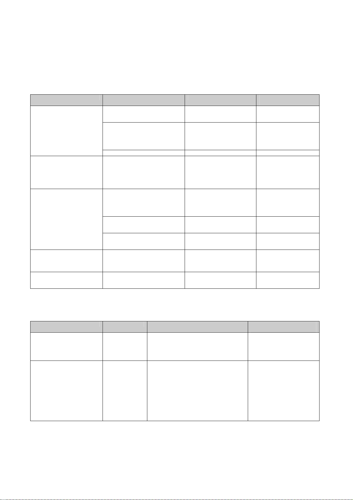
Service Manual BV Family R1.2 Section 3
DICOM configuration
9.3 USAGE PROBLEMS (MVS)
9.3.1 Transfer of images to Storage/Print target fails
Error text (MVS) Error in log file Cause Solution
No connection.
Please check the network
connection
After a timeout:
No connection.
Please check the network
connection
Failed.
Please check the target
configuration
After timeout:
Failed.
Connection with the selected
target timed out
Failed.
Printer is not ready
Could not open association with
<target name>: network cable
disconnected
TCP init error (first connect call)
Transport unexpectedly closed
DCM Could not open association
with <target name>: [Failed to
connect to remote host]
Peer aborted Association The target aborted the transfer. Check the target.
TCP init error, timeout in select call
Transport unexpectedly closed
DCM Could not open association
with <target name>: [Failed to
connect to remote host]
Could not open association with
<target AE>: [Connection aborted
before association
negotiation was completed]
DCM Could not open association
with <target AE>: [Association
negotiation failed]
C_STORE_RSP: error: <reason>
example <refused; no resources>
DCM Receive message timed out A timeout occurred while
PrintMessage::InterpretPrinterStatus
: PRINTER FAILURE: <reason>
example: PRINTER BUFFER FULL
BV Family has been
disconnected from the network.
Both the BV Family and the
target are connected to the
network but probably no
DICOM SCP is running on the
target.
The target is not connected to
the network or
the target is on a different
subnet or
other networking problems.
There was a timeout during the
association. Probably the
network is busy.
The target rejected the
association.
The target sent an error in the
response message of a
transfer.
waiting for a response
message from the target.
The printer is not ready. Check the exact problem
Connect the BV Family to
the network
Start DICOM SCP on the
target.
Connect the target to the
network or configure the
subnet mask of the target
or contact the network
administrator.
Increase the “Association
Reply Timeout” in the
Network Configuration in
BV-Scope.
Check the configuration on
the target.
Check the target.
Increase the “Receive
Message Timeout”.
in the log file. Check the
printer.
9.3.2 Printed images are not as expected
Error text (MVS) Error in log file Cause Solution
Are the images on a print-job
output too dark or too light?
No →
Yes ↓
→ →
→
Correct configuration of printer parameters?
No →
Yes ↓
Refer to the display of the printer, its log file
and/or its manual.
Are the printer parameter settings ok?
No →
Yes ↓
Problem with printer.
Check the printer configuration
and the printer parameters on
the service PC and on the
printer.
Change the
minimum/maximum density
settings in the printer
parameters.
The settings can be found
under: /Program Manual
/DICOM Target Configuration
/Printer Targets.
For the default printer settings
refer to the corresponding
chapter in SM-SW section 2.
BV Family R1.2 / Volume 1 (04.1) SM-SW 3 - 25
ALL RIGHTS RESERVED
© 2004 Koninklijke Philips Electronics N.V.
Page 72

Section 3 Service Manual BV Family R1.2
DICOM configuration
9.3.3 Queue problems
Error text (MVS) Error in log file Cause Solution
Not possible to queue the
exam for export/print. Exam
export queue is full.
Has the target been connected to the
Is the target running a DICOM Storage
→
Has the BV Fam. system been connected to
the network?
No →
Yes ↓
network?
No →
Yes ↓
Service Class Provider application?
No →
Yes ↓
When the problem remains, remove the
queued export sessions from the queue via
the service PC.
Connect the BV Fam. system
to the network.
Connect the target to the
network.
Connect a DICOM Storage
Service Class Provider
application.
SM-SW 3 - 26 (04.1) BV Family R1.2 / Volume 1
ALL RIGHTS RESERVED
© 2004 Koninklijke Philips Electronics N.V.
 Loading...