

Page 1

TRAINING GUIDE
Avalon Fetal Monitor
FM20 / FM30 / FM40 / FM50
Release F.0 with Software Revision F.01.xx
FETAL MONITORING
Page 2

Philips Medizin Systeme Boeblingen GmbH
Hewlett-Packard-Str. 2
71034 Boeblingen
Germany
© Copyright 2003 - 2008.
Koninklijke Philips Electronics N.V.
All Rights Reserved.
Printed in Germany 12/08
*453564129711*
4535 641 29711
Page 3

4535 641 29711
1Table Of Contents
1 Introduction 1
About this Guide 1
How to use this Training Guide 1
Symbols 1
Generating Data 2
Activating Demo Mode 2
Exiting Demo Mode 2
Demo Mode and OB TraceVue 3
References 3
2 Training Objectives 5
Competency Statement 5
Performance Objectives 5
3 Overview 7
Avalon FM20/FM30 7
Avalon FM40/FM50 8
Tr a n s d u c e r s 9
Related Product 10
User Interface 11
Touchscreen Operation 11
Operating and Navigating 12
Keys 13
Loading Paper 15
4 Basics 19
Switching On 19
Monitoring FHR using Ultrasound 19
Monitoring Uterine Activity Externally 21
Recording Data 21
Switching the Monitor to Standby 22
Switching Off 22
5 Standard Functions 23
Fetal Measurements 23
Monitoring FMP using Ultrasound 23
Monitoring FHR using DECG 24
Monitoring Uterine Activity Internally 26
Cordless Transducer System - Avalon CTS 28
Monitoring Twins and Triplets 30
Maternal Measurements 32
Monitoring Noninvasive Blood Pressure (NBP) 32
I
Page 4

Monitoring SpO2 and Pulse Rate 33
Cross-Channel Verification 35
Monitoring MECG 35
General Parameters 37
Entering Notes 37
Marking an Event 37
Admitting, Transferring and Discharging Patients 39
Fetal Monitor Connections 47
Connection Status Indicator 48
6 Changing Settings 49
Alarms 49
Switching NBP On/Off manually 51
Adjusting Tone Volume 52
Stored Data Recording 52
Setting Non-Stress Test Timer 53
II
Page 5

About this Guide
This training guide assists you, as a trained healthcare professional, using the Avalon FM20, FM30,
FM40, and FM50, to learn the basic functions of the monitors. It is task-oriented, providing a fast,
hands-on introduction to the monitor.
In the Overview, a short introduction gives you an quick outline of the monitor.
The training is divided into three sections:
Basics provides information about the fetal
monitor. By going from task to task you will
learn to start monitoring immediately after
switching on the monitor.
In Standard Functions, you will learn about
monitoring all the maternal and fetal
measurements.
Changing Monitor Settings familiarizes you
with the monitor settings.
1
1Introduction
Basics
Functions
Standard
Functions
Changing
Monitor Settings
How to use this Training Guide
This Training Guide leads you step-by-step through the basic functions of the monitor. Work through
all the steps sequentially in the order they are presented. Use this guide in conjunction with an Avalon
Fetal Monitor and its Instruction for Use (IfU).
Symbols
To become familiar with your monitor, you go step-by-step from task-to-task. These tasks are
indicated by a pointing finger symbol.
Places where we recommend you to refer to the IfU are indicated by a book symbol.
The locomotive symbol indicates additional information for fetal monitors which are connected to
OB TraceVue (Rev. F). In that case, use this guide also in conjunction with OB TraceVue and its
Instruction for Use (IfU).
1
Page 6
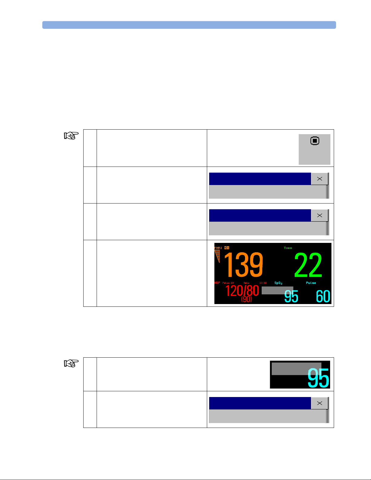
1 Introduction Generating Data
Generating Data
Most of the patient data required for this training can be generated in the monitor’s Monitoring mode.
Sometimes you will need to apply a measurement sensor to yourself. For some exercises, you have to
use the fetal monitor’s Demo mode. During this training, you will need to switch between Demo and
Monitoring modes. The operating mode you will need is indicated at the side of each task.
Activating Demo Mode
Demo mode is for demonstration and training purposes only. Never use Demo mode when a patient is
attached to the monitor.
1 Select the Main Setup SmartKey.
Main
Setup
2 In the Main Setup menu, scroll down and
select Operating Modes.
Operating Modes
Main Setup
3 From the Operating Modes menu, select
Demo.
4 Using the pop-up keyboard, type in the
password 14432 and select Enter.
Numeric values or readings appear together
with a flashing Demo flag.
Exiting Demo Mode
When you have completed your training tasks, always exit Demo mode. When you leave Demo mode,
the monitor clears all demo data from the monitor’s memory and uses the default settings. For
example, if you changed the FHR tone in Demo mode to a special value, you need to change it again to
the same value in Monitoring mode.
1 Select the flashing Demo flag on the screen
to exit the Demo mode.
Operating Modes
Demo
DEMO
D E M O
2 From the Operating Modes menu, select
Monitoring.
To exit the Demo Mode, it is also possible
to cycle power.
2
Monitoring
Operating Modes
Page 7

References 1 Introduction
Demo Mode and OB TraceVue
The fetal monitor’s demo data is not transferred to OB TraceVue when connected with a serial
connection (RS232).
Demo data is transferred to OB TraceVue when the fetal monitor is connected via LAN, and both the
fetal monitor and OB TraceVue are in Demo Mode.
References
This training guide is additional to, and does not replace, the monitor’s IfU. It is an initial training
tool. For full operating instructions and safety-related information, it is essential to read and follow the
IfU. For applicable warnings and precautions refer to the IfU of the respective fetal monitor.
Before monitoring patients you must have a comprehensive understanding of patient monitoring.
The following documentation was shipped with your Avalon Fetal Monitor:
• Instructions for Use
•Quick Guide
• Avalon training video (FM 20/30 only)
• Fetal Monitoring Documentation DVD, which contains the service guide, this training guide, and
the above documents as pdf files (readable with Adobe Reader), as well as all other documents
associated with this monitor:
– application notes (English only)
– configuration guide (English only).
The DVD can be used as a source of reference or to print additional copies of the documents. To
purchase printed copies of any documentation, or to purchase additional copies of the DVD, please
contact:
Globalware Solutions
Tel: +1-800-527-6871; Fax: +1-978-469-7529; e-mail: [email protected].
3
Page 8

1 Introduction References
4
Page 9

2Training Objectives
Competency Statement
You will be able to perform fundamental monitoring functions.
Performance Objectives
You will be able
• to explain or demonstrate the:
–monitor controls, indicators and connectors
–operation and navigation using the touchscreen and the SmartKeys
–measurement values and waves
2
• to acquire, manage, and to evaluate fetal data:
–fetal heart rate (FHR) and fetal movement profile (FMP) by using ultrasound (US)
–fetal heart rate (FHR) by using direct ECG (DECG)
• to acquire, manage, and to evaluate maternal data:
–uterine activity externally (Toco)
–internal uterine activity (IUP)
–noninvasive blood pressure (NBP)
and pulse rate
–SpO
2
–maternal ECG (MECG)
–notes and events
–admission, transfer and discharge
• to use the monitor together with the cordless transducer system Avalon CTS
• to monitor twins and triplets
• to change monitor settings and evaluate alarm and data history:
–alarm settings
–measurement settings
–printing data
• to set the non-stress test timer
• to activate and deactivate Demo mode.
5
Page 10

2 Training Objectives Performance Objectives
6
Page 11
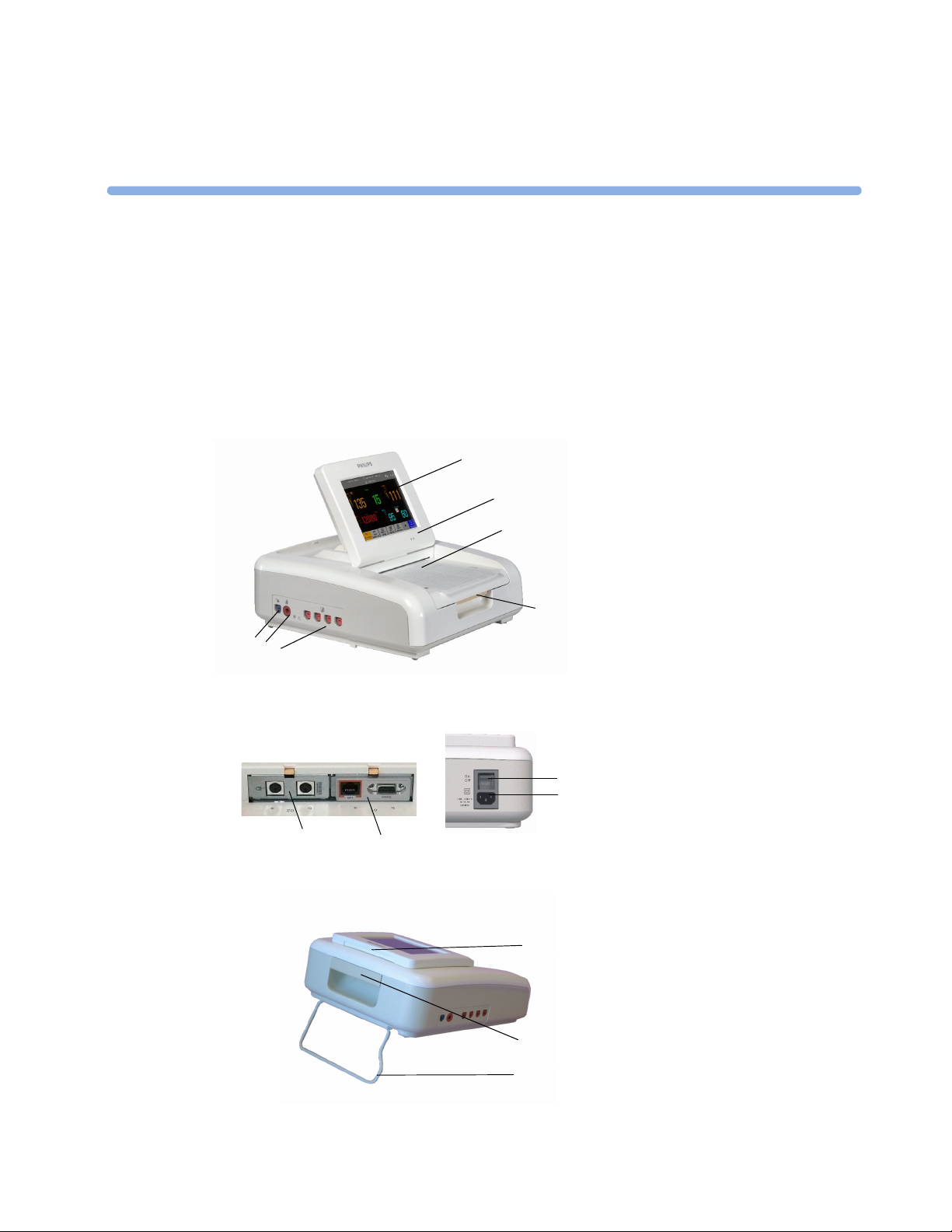
Avalon FM20/FM30
3
3Overview
1 To u ch scr ee n d isp la y
1
2
3
2 Power LED
3 Paper drawer
4 Paper drawer release
5
Fetal sensor sockets, or event marker
6
Noninvasive blood pressure socket
7
SpO2 socket
4
7
6
5
8
On/Off switch
9
Power connector
10
Slot 01 for optional LAN / RS232
system interface
11
8
9
10
12
13
14
Slot 02 dual PS/2 system interface
11
for mouse and keyboard connection
12
Display release
13
Carrying handle
14
Built-in stand
7
Page 12
3Overview Avalon FM40/FM50
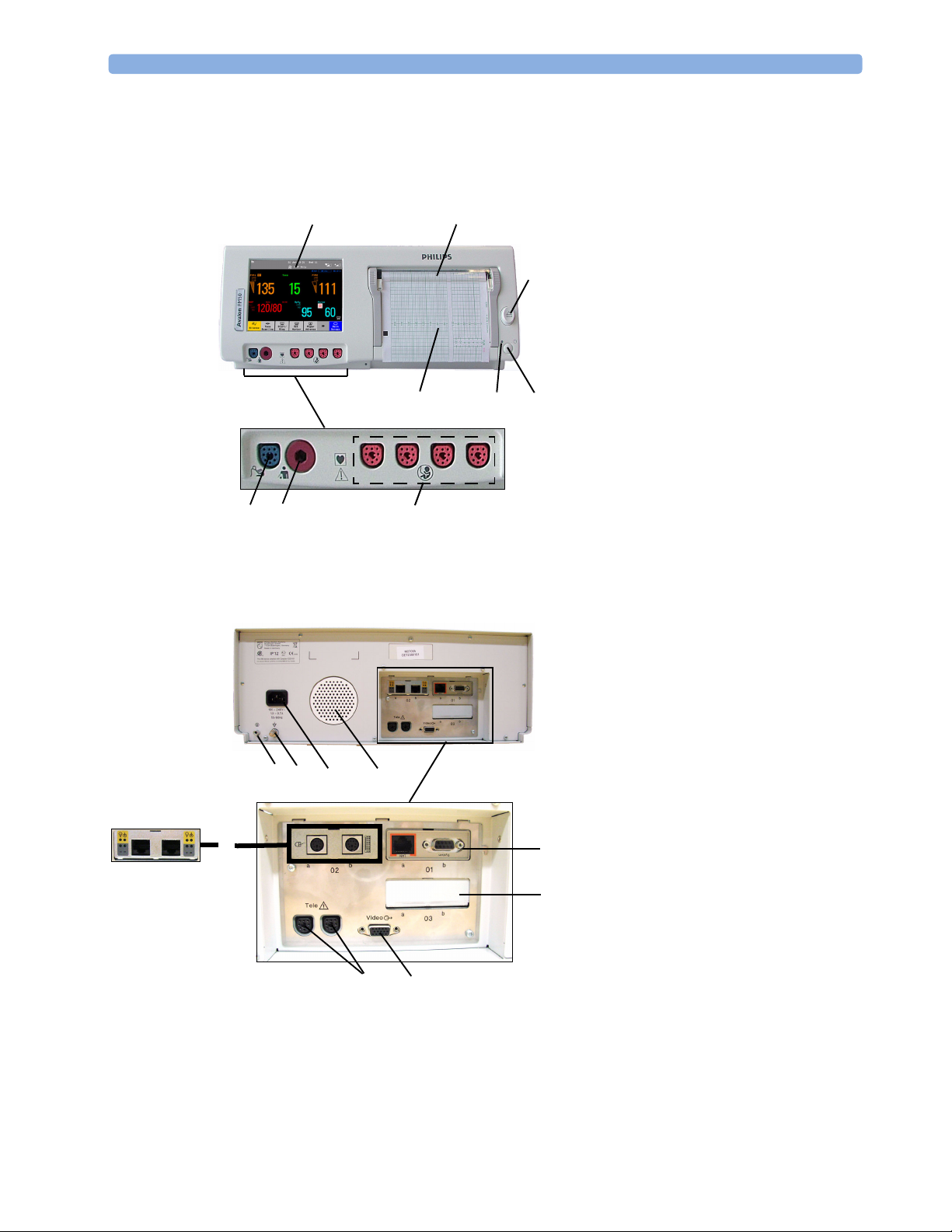
Avalon FM40/FM50
1 Touchscreen color display
1
8
7
9
2
3
6
5
2 Transparent paper guide with tear-off
edge
3 Paper eject button
4 On/Off/Standby switch
5 Power LED
6 Recorder paper table
7 SpO
8 Noninvasive blood pressure socket
4
9 Fetal sensor sockets
socket
2
1 Reserved for future use: protective
earth intended for use in system
installations.
2 Equipotential grounding point
3 Power connector
4 Loudspeaker
5 Slot 01 for LAN / RS232 system
12
9
3
4
6 Slot 03 for future use
(A)(B)
7 Video output (VGA)
8 Telemetry interface
5
9 Slot 02 for optional interfaces:
6
8
7
interface
• Either dual PS/2 system interface
(A) for mouse and keyboard
connection)
• Or MIB interface (B) for external
touch screen connection
8
Page 13
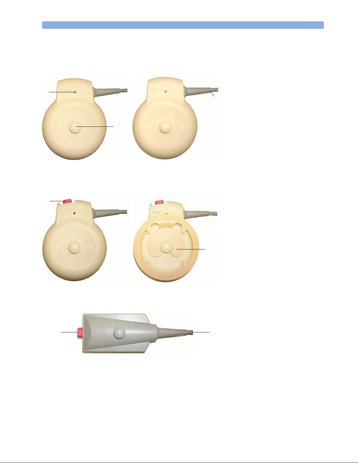
Transducers 3Overview
Transducers
1
Transducer finder LED
2
Belt button
1
2
3
3
Cable to any of the four fetal
sensor sockets on the monitor
To c o Tra ns d uc e r
(M2734A)
4
+
Toco
Tr ansducer w ith ECG/ IUP
capability (M2735A)
6
Ultrasound Transducer
(M2736A)
4
Connector - for connecting
ECG/IUP adapter cables
+
(M2735A Toco
transducer
only)
5
Butterfly belt clip for use with
5
belts without button holes
6
Connector - for connecting
ECG/IUP adapter cables (same
+
as for Toco
7
7
Cable to any of the four fetal
transducer)
sensor sockets on the monitor
Patient module for ECG/IUP
(M2738A)
9
Page 14
3Overview Related Product
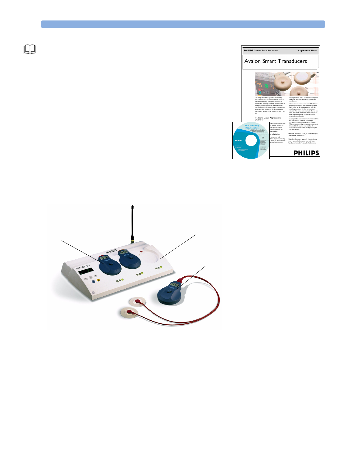
For detailed information about transducers, read the “Avalon Smart
Transaducers” application note (English only) on the “Fetal Monitor
Documentation” DVD.
Related Product
1
Cordless Transducer
2
Base station
2
1
3
Avalon CTS (M2720A)
Cordless Fetal Transducer System
3
ECG Transducer
10
Page 15
User Interface 3Overview
User Interface
The link between you and the monitor is the “user interface”. The user interface of a monitor’s display
is called “Graphical User Interface” (GUI).
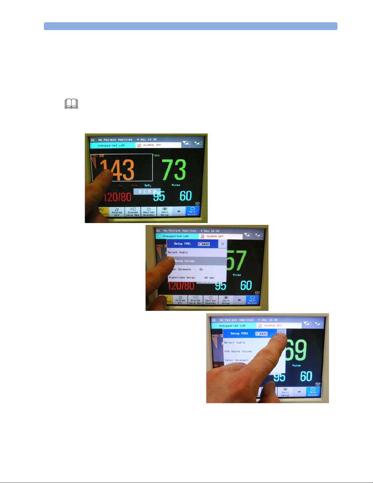
Touchscreen Operation
Your monitor has a touchscreen. Everything you need to operate the monitor, other than to turn it on
and off, is contained on its screen. For example, when you touch a measurement numeric, that
measurement’s Setup menu opens, from which you can make your selection. This may be another
menu, or a pop-up list from which to choose an item.
Setup FHR1 menu
11
Page 16
3Overview User Interface
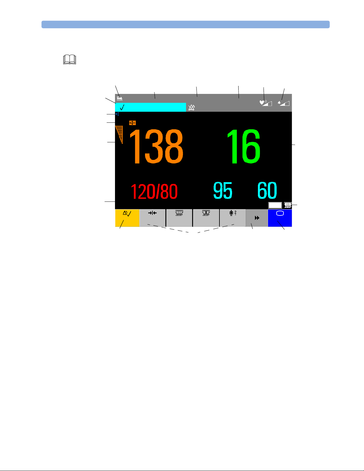
Operating and Navigating
Most screen elements are interactive. Screen elements include measurement numerics, screen keys,
information fields, status indicators, alarms fields and menus.
1
15
23 4
Doe, Jane
FHR2 UNPLUGGED
18
17
NST
FHR1
20 min
00:12 30
16
Pulse 60
NBP
Sys.
All Settings restored successfully
Silence
Baseline
Man 08:28
Toco
Start/
Stop
14
31 Jan
INOP Only
SpO
Paper
Advance
13
13:31
Toco
2
5
Bed 11
Admit/
Dischrge
67
Pulse
TELE
Main
Screen
12
8
9, 10
11
1 INOP and alarm status area
2 LAN connection status indicator
3 Patient identification
4 Date and time
5Bed label
6 Fetal heart sound volume adjust/indicator
7 Alarm volume adjust/indicator
8 Numeric/measurement values
9 Status indicator for Avalon CTS system
10 Status indicator for fetal trace recorder
11 Main Screen SmartKey
12 Scroll to display more SmartKeys
13 SmartKeys
14 Silence key
15 Status line - shows status and prompt messages
16 Signal quality indicator
17 Measurement label
18 NST timer (off by default)
12
Page 17
User Interface 3Overview
Keys
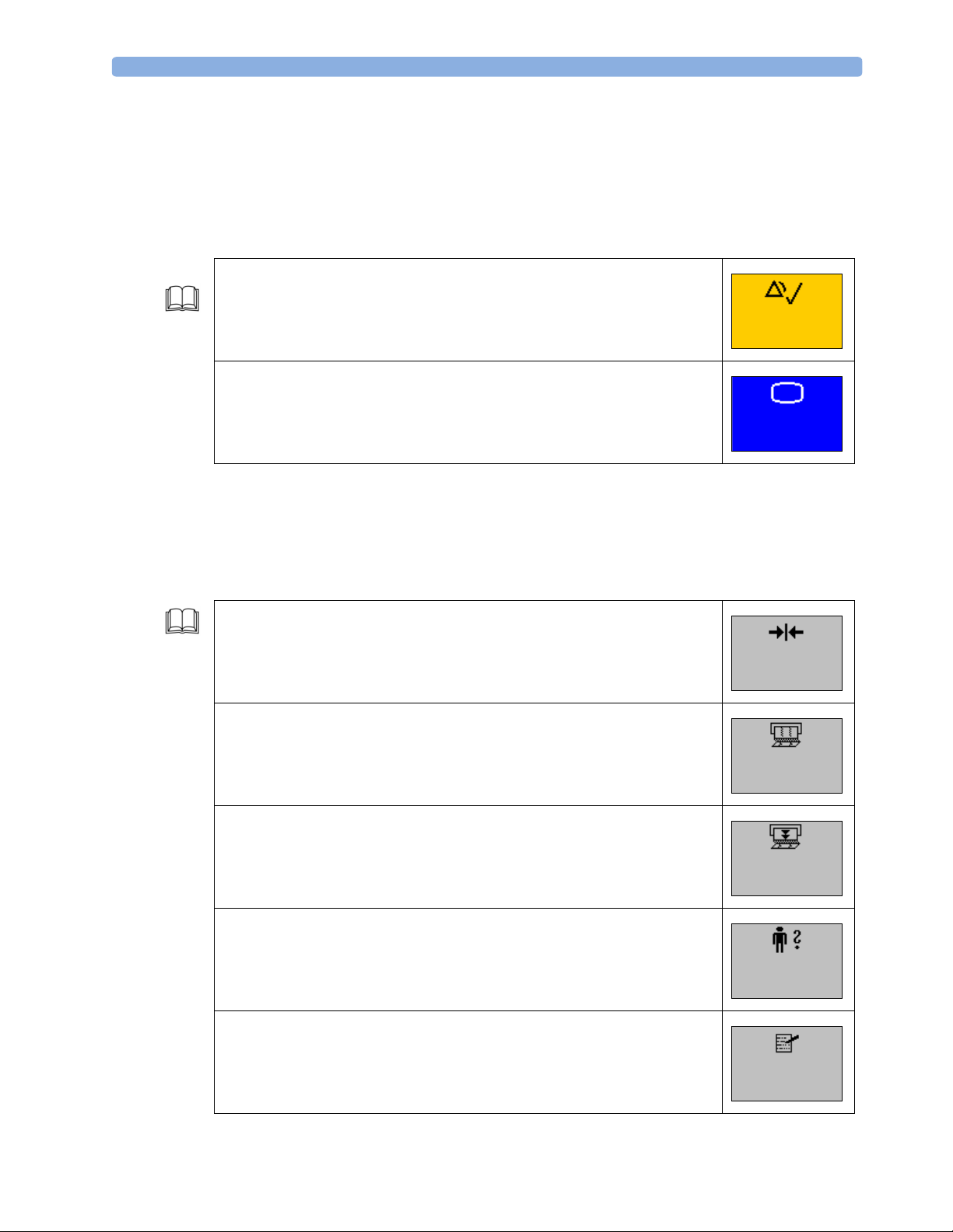
The monitor has three different types of keys. They are called Permanent keys, SmartKeys, and Pop-up
keys.
Permanent Keys
A Permanent key is a graphical key that remains permanently on the screen.
Silence - acknowledges an active alarm by switching off audible alarm
indicators. The acknowledgement is visible by a checkmark displayed in the
visible alarm bar.
Silence
SmartKeys
Main Screen - closes all open menus and windows and returns to the main
screen.
SmartKeys are graphical keys, located at the bottom of the main screen, and configurable in the
monitor’s Configuration mode. They give you fast access to functions. The selection of SmartKeys
available on your monitor depends on your monitor configuration and on the options purchased. The
SmartKeys in the following table are the default SmartKeys of your monitor.
Reset Toco baseline
Start and stop trace recorder
Main
Screen
Toco
Baseline
Start/
Stop
Paper advance to the next fold
Admit and discharge a patient
Enter notes
Paper
Advance
Admit/
Dischrge
Enter
Notes
13
Page 18
3Overview User Interface
Start and stop manual NBP measurement
Start automatic NBP measurement series
Stop current automatic NBP measurement. Automatic mode remains active.
Stop all NBP measurements
Set time interval between two NBP measurements
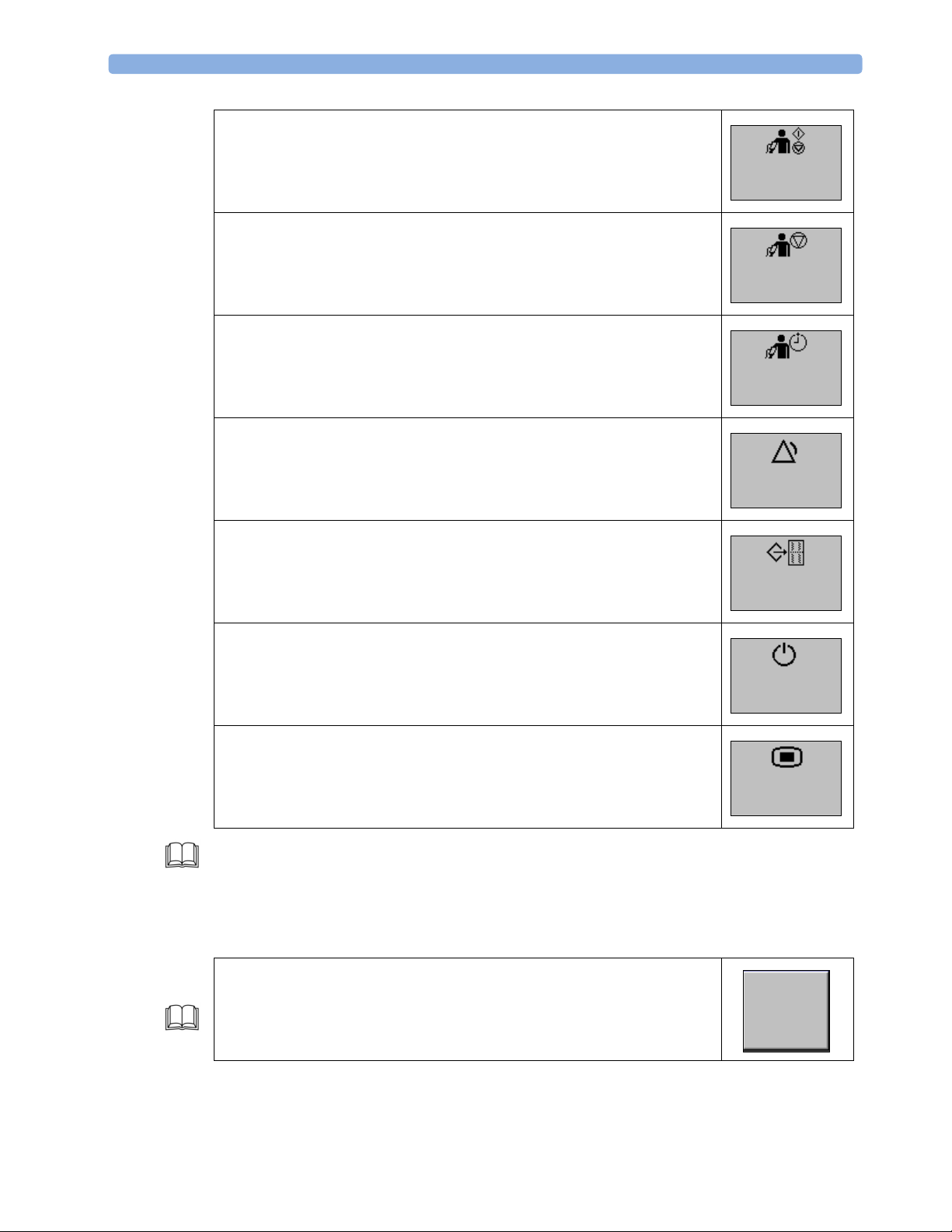
Alarms off (if pause duration is infinite)
Pause alarms
Re-enable alarm indicators
Print trace data from the monitor’s memory
Start/
Stop
Stop
All
Repeat
Time
Alarms
Off
Stored
Data Rec
Pop-Up Keys
Enter standby mode
Enter Main Setup menu
Additional SmartKeys are described in the IfU (see “Basic Operation - Keys - SmartKeys” in the IfU).
Pop-up keys are context-sensitive graphical keys that appear automatically on the monitor screen when
required.
For example, the Confirm pop-up key appears when you need to confirm a change.
Monitor
Standby
Main
Setup
Confirm
14
Page 19
Loading Paper 3Overview
Loading Paper
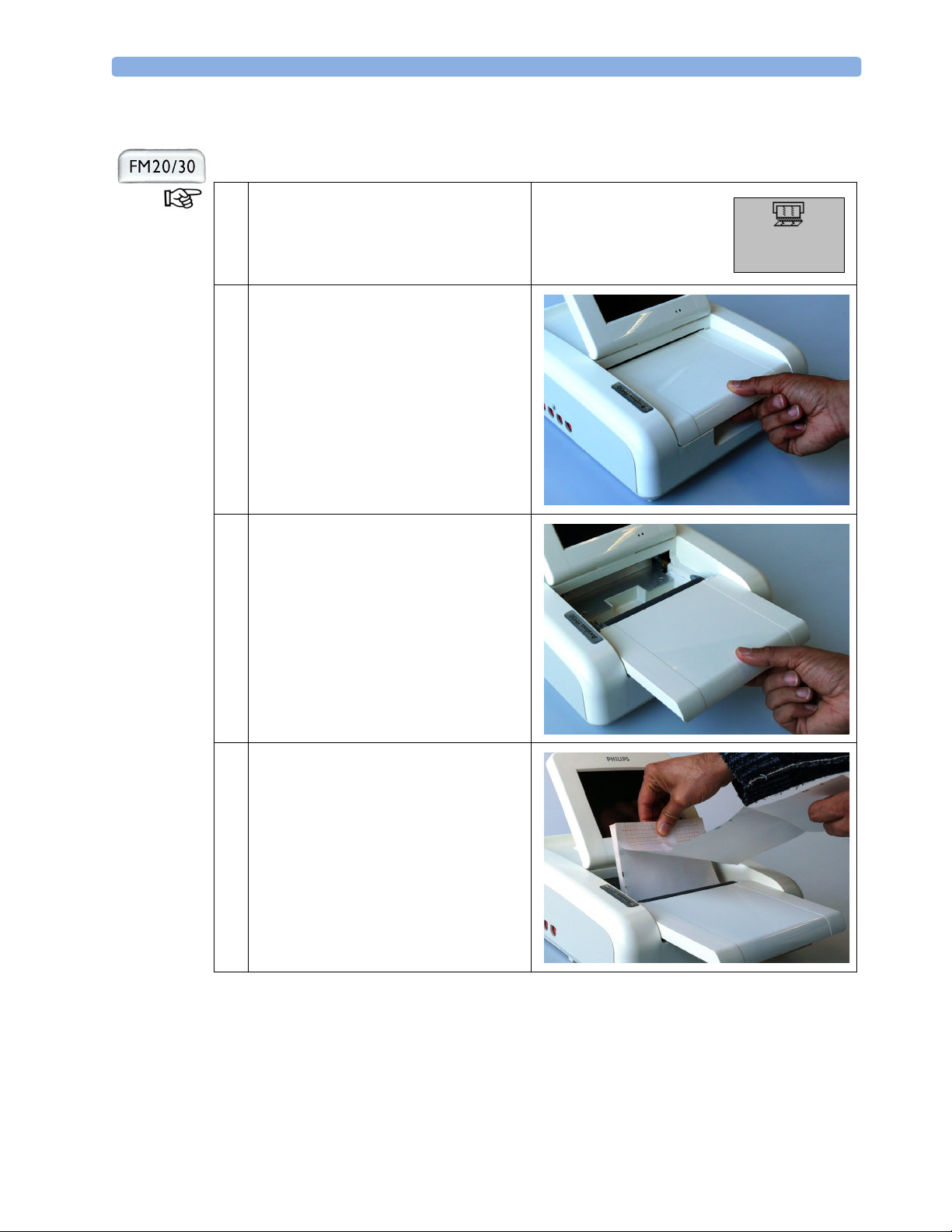
1 If the recorder is on, press the recorder
Start/Stop Smartkey or the Stop
Recording SmartKey to turn it off.
2 Press the table release to unlock the paper
drawer.
Start/
Stop
3 Pull the table forward to open it fully.
Remove any remaining paper from the tray.
4 Unfold the top page of the pack and
position the uterine activity scale on the
right.
The bottom side is indicated by the word
STOP printed on the final page of the new
pack.
Slide the pack into the tray, with the
bottom side down.
15
Page 20
3Overview Loading Paper
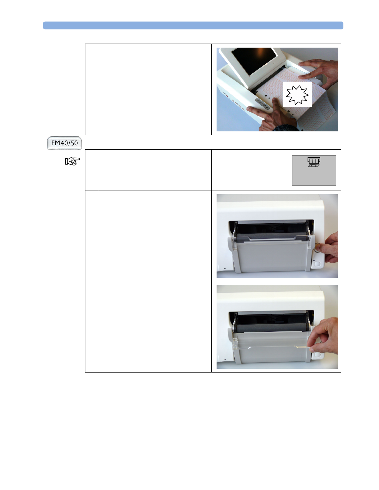
5 Push the paper drawer back, securing the
paper with your fingers, until you hear a
“click” that indicates the table release is
closed.
To switch on the recorder, see “Recording
Data” on page 21.
Click
1 If the recorder is on, press the recorder
Start/Stop Smartkey or the Stop
Recording SmartKey to turn it off.
Start/
Stop
2 Press the Paper Eject button to unlock the
paper drawer.
Remove any remaining paper from the tray.
3 Move the Transparent Paper Guide
forward.
16
Page 21
Loading Paper 3Overview
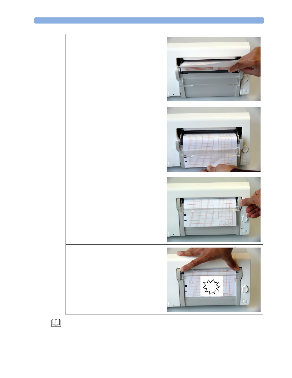
4 Unfold the top page of the pack and
position the Uterine Activity Scale on the
right.
The bottom side is indicated by the word
STOP printed on the final page of the new
pack.
Slide the pack into the tray, with the
bottom side down.
5 Feed the paper evenly through the paper
guide.
Do not close the paper guide yet.
6 Close the paper drawer.
7 Now close the paper guide.
When you hear the “click”, the paper guide
is closed.
To switch on the recorder, see “Recording
Data” on page 21.
Click
For further information about the Fetal Recorder, see “Basic Operation - Loading Paper” in the IfU.
17
Page 22

3Overview Loading Paper
18
Page 23
Switching On
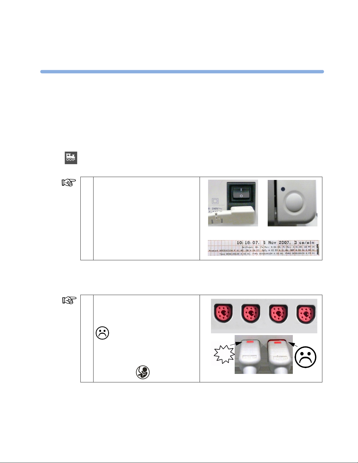
When the monitor is connected to an OB TraceVue system, switch on the monitor before performing
any transfers to this monitor.
Monitoring Mode
4
4Basics
1 Press the power switch to turn on the
monitor.
“Self-Test OK”, the serial number, and
revisions for the software and firmware are
printed on the fetal trace paper (if recorder
Autostart is configured to On).
On
Off
FM 20/30
Monitoring FHR using Ultrasound
Monitoring Mode
1 Place the FHR transducer into the socket.
Push gently until you hear it “click” into
position.
This symbol indicates that the FHR
transducer is not pushed far enough
into the socket.
FM 40/50
Fetal Sensors
Use any of the four fetal sensor sockets
labeled with the words “Fetal Sensors” or
with the symbol .
Click
19
Page 24
4Basics Monitoring FHR using Ultrasound
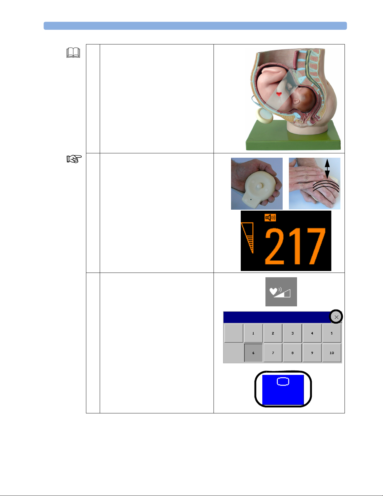
2 Confirm fetal life before starting
monitoring.
Prepare for ultrasound monitoring and
place the transducers as described in the IfU
(see “Monitoring FHR and FMP Using
Ultrasound - Preparing to Monitor” in the
IfU).
3 Generate an artificial FHR. Note what
happens to the numeric display, the FHR
tone, and the signal quality indicator.
4 To open the Fetal Heart Sound Volume
menu, touch the tone volume symbol on
the right-upper corner of the display.
Change the fetal heart sound volume to
different volumes and hear the differences
by again generating an artificial FHR.
To close the menu, select the Main
Screen SmartKey, which is permanently
in the bottom-right corner of the display.
There are different ways to get to a specific
point in the menu. To close open menus, it
is recommended to use the Main Screen
SmartKey.
FHR1
Fetal Heart Sound Volume
Off
Main
Screen
20
Page 25
Monitoring Uterine Activity Externally 4Basics
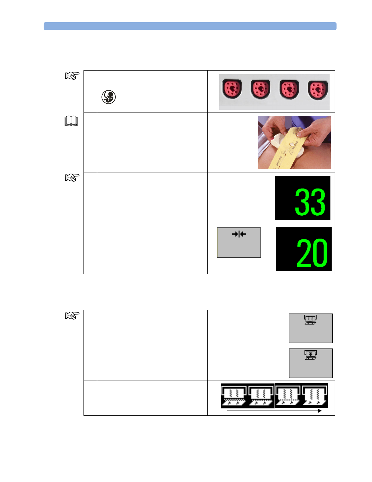
Monitoring Uterine Activity Externally
Monitoring Mode
1 Connect the Toco transducer. Use any of
the four fetal sensor sockets marked
or “Fetal Sensors”.
Fetal Sensors
2 Fasten the abdominal belt as described in
the IfU (see “Monitoring Uterine Activity
Externally” in the IfU).
3 To open the Setup Toco menu, select the
Toco numeric.
4 Press the Toco Baseline SmartKey to
reset the Toco baseline to 20 on the display
and trace.
Recording Data
Monitoring Mode
1 To switch the recorder on or off, press the
Start/Stop SmartKey.
2 You can advance the paper automatically to
the next fold by pressing the Paper
Advance SmartKey at any time except
during a stored data recording.
Toco
Toco
Toco
Baseline
Start/
Stop
Paper
Advance
3 If the recorder is running, the running
“recorder on” status indicator is displayed
above the Main Screen SmartKey on the
screen.
21
Page 26
4Basics Switching the Monitor to Standby
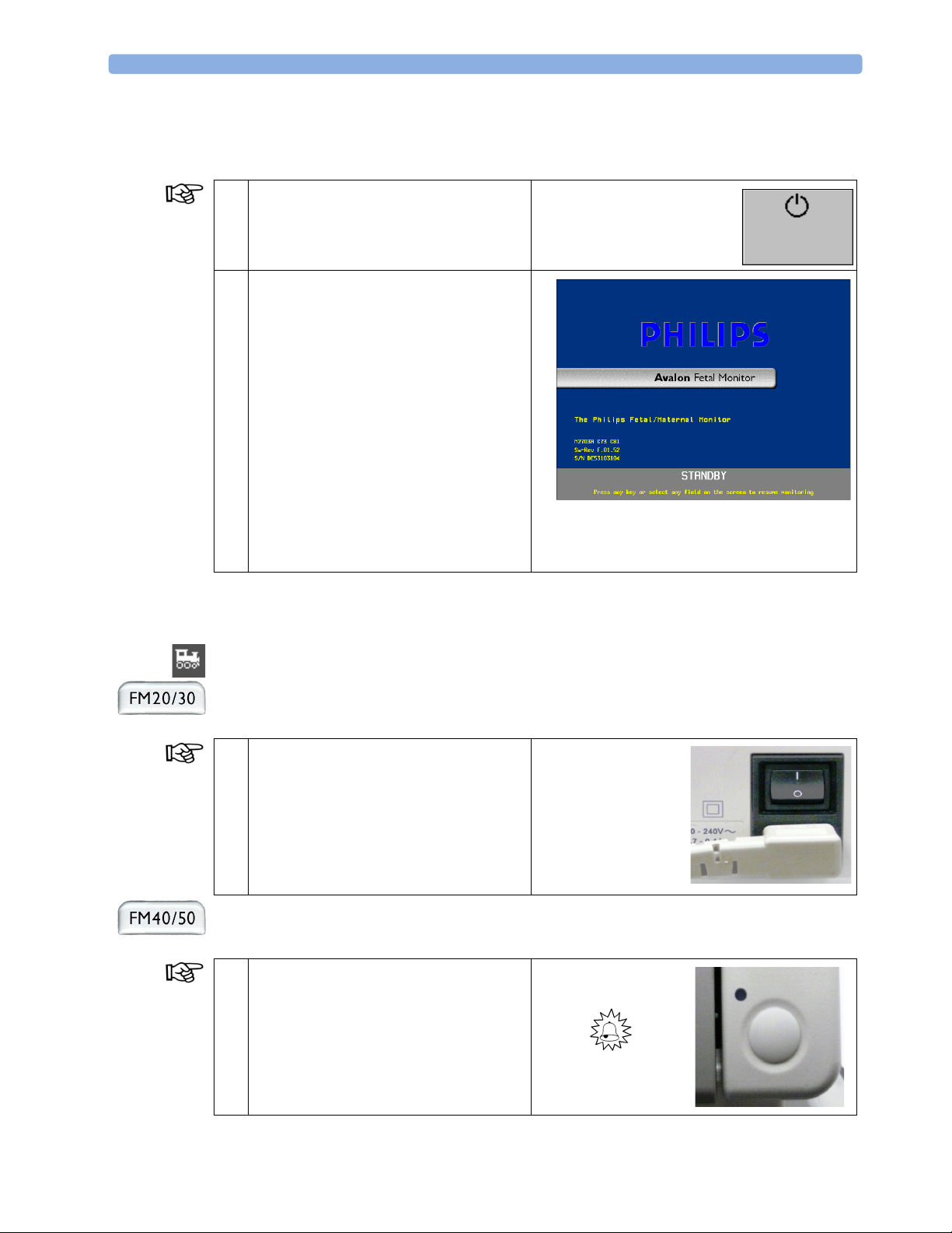
Switching the Monitor to Standby
Monitoring Mode
1 Select the Monitor Standby
SmartKey to place the monitor into
Standby mode.
2 All waves and numerics disappear from the
display, but all settings and patient data
information are retained. A running NBP
automatic series measurement will be
stopped when Standby mode is entered.
A special Standby screen is displayed and
the screen will dim. Power consumption is
reduced.
Press any field on the screen to resume
monitoring.
If desired, resume the NBP automatic series
measurement as described in “Monitoring
Noninvasive Blood Pressure (NBP)” on
page 32.
Monitor
Standby
Switching Off
When the monitor is connected to an OB TraceVue system, perform pending transfers before
switching off the monitor.
Monitoring Mode
1 Press the power switch to turn off the
monitor.
Monitoring Mode
1 Press the power switch to turn off the
monitor. This switch does not disconnect
the monitor from AC power. To
disconnect, unplug the power cord from
the AC mains socket.
On
Off
22
A beeper warns you if the monitor is
disconnected from AC mains.
Page 27
5Standard Functions
Fetal Measurements
Monitoring FMP using Ultrasound
Monitoring Mode
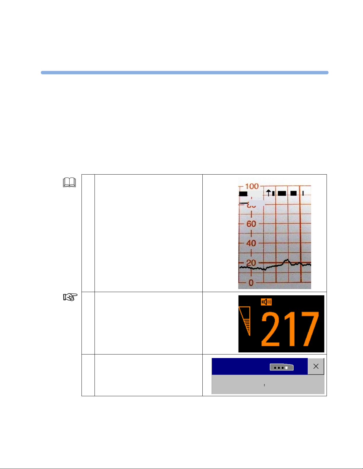
1 The Fetal Movement Profile FMP detects
fetal movements on the FHR1 channel via
an ultrasound sensor and marks “activity
blocks” along the top of the Toco scale on
the paper tray.
In our training it is not simple to generate
FMP onto the paper trace. For a good
understanding of the FMP measurement,
see “Monitoring FHR and FMP - Fetal
Movement Profile” in the IfU.
5
FMP
Toco
2 Select FHR1 numeric to open the Setup
FHR1 menu.
3 In the Setup FHR1 menu, select Fetal
Movement to toggle between On and
Off.
FHR1
Setup FHR1
Fetal Movement On
23
Page 28
5 Standard Functions Fetal Measurements
Monitoring FHR using DECG
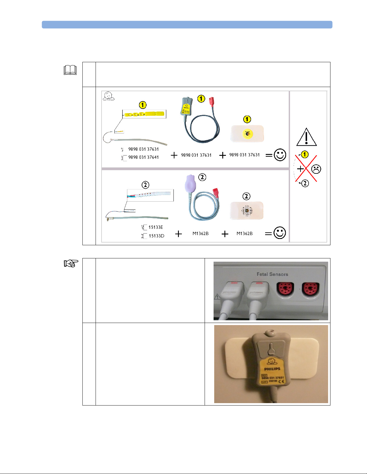
1 Make sure that you are using the parts and combinations of the equipment as described in
“Monitoring FHR using DECG - What you need” and “Accessories and Supplies - DECG
Accessories: Component Compatibility” in the IfU.
1
Monitoring Mode The standard procedures in use in your facility determine the appropriate sequence of actions.
1 Depending on the equipment you are
using, ensure that either the Toco
+
transducer or the patient module is
connected to a free sensor socket of the fetal
monitor.
2 Attach a pre-gelled attachment electrode to
the DECG adapter cable.
Fix the attachment electrode to the
Mother’s thigh.
24
Page 29
Fetal Measurements 5 Standard Functions
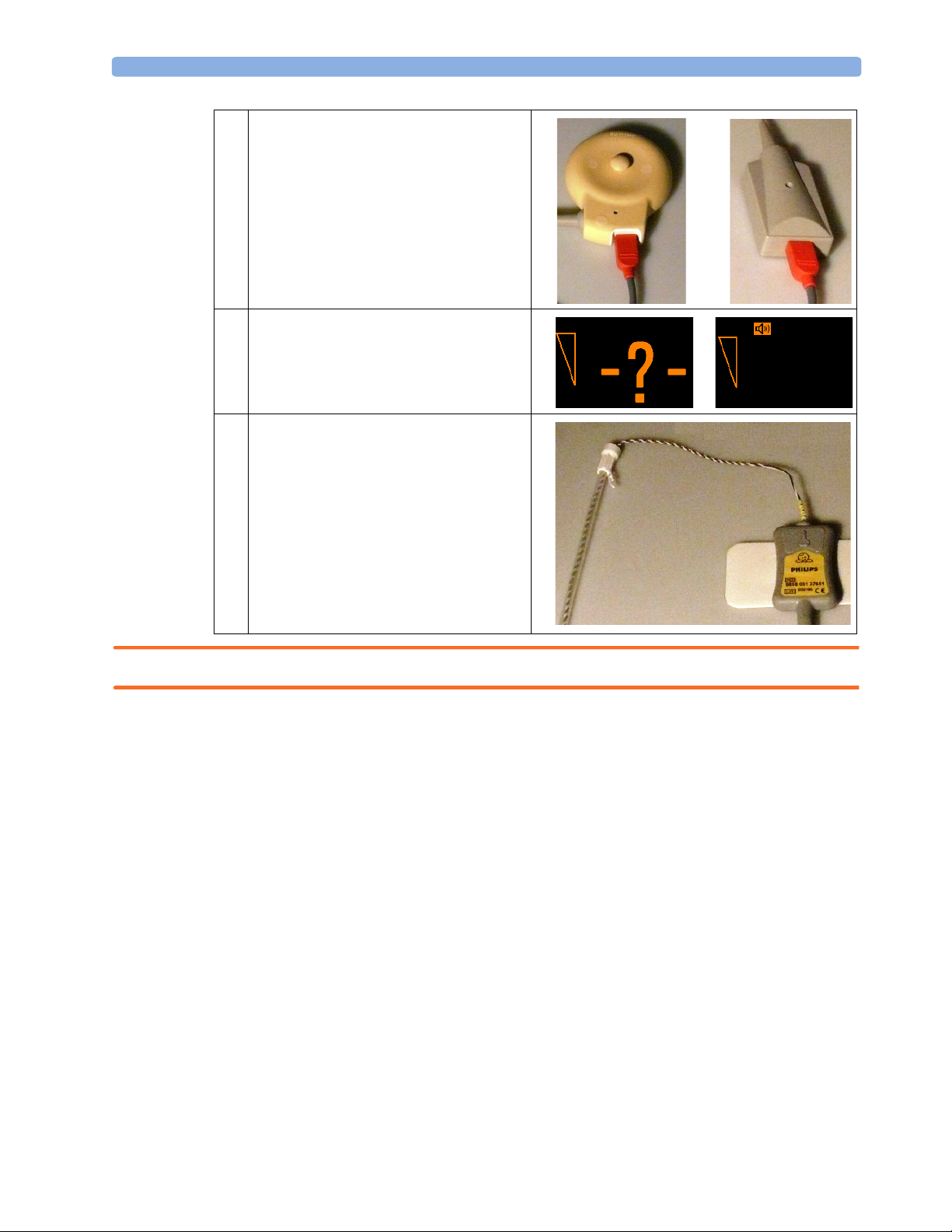
3 Depending on the equipment you are
using, connect the red connector plug of
the DECG adapter cable either to the
+
Toco
transducer or the Patient Module.
4 DFHR appears on the left-upper corner
DFHR
FHR1
together with a question mark. FHR1
switches to the right-upper corner.
5 Attach the Fetal Scalp electrode to the fetus.
Connect the fetal scalp electrode to the
DECG adapter cable.
WARNING NEVER connect the fetal scalp electrode to anything other than the correct DECG adapter cable.
25
Page 30
5 Standard Functions Fetal Measurements
Demo Mode Since it is not possible to obtain real DECG values via the scalp electrode during this training, and you
might have no access to a simulator, enter the monitor’s Demo mode (see “Activating Demo Mode” on
.
page 2)
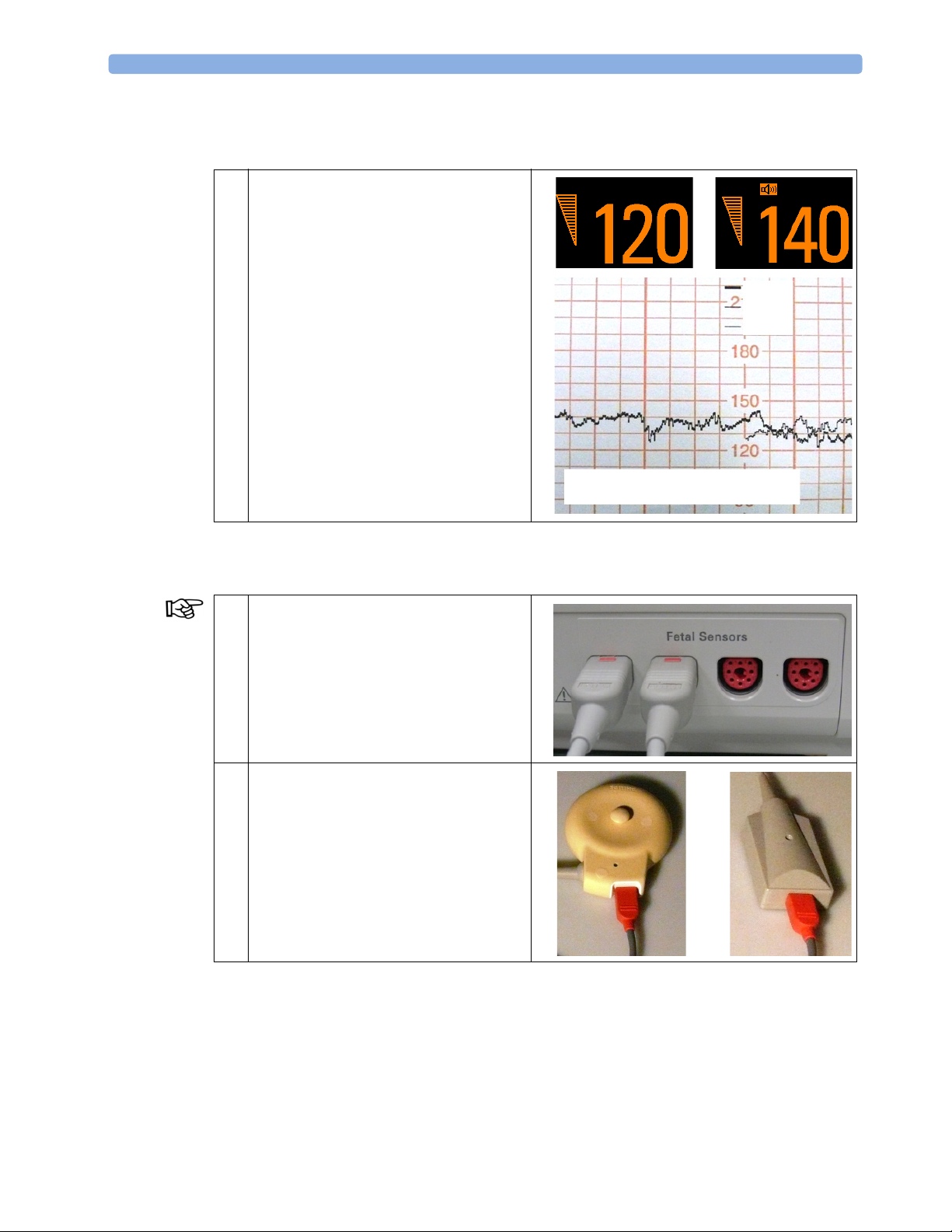
6 The DFHR numeric appears on the left-
upper corner.
On a running paper trace, DFHR appears
as a new measurement.
Be aware that in Demo mode the values are
different, as if you would monitor twins.
When monitoring one fetus, using FHR
and DFHR, the values coincide. The crosschannel verification feature detects this, a
“?” appears on the screen and is repeatedly
printed on the trace paper every 30 seconds.
As soon as you disconnect the US
transducer, FHR1 disappears from the
screen and the paper trace.
Exit Demo mode (see “Exiting the Demo
Mode” on page 2).
DFHR
Demo Data
FHR1
FHR1
DFHR
Pulse
Monitoring Uterine Activity Internally
Monitoring Mode The standard procedures in use in your facility determine the appropriate sequence of actions.
1 Depending on the equipment you are
using, ensure that either the Toco
transducer or the Patient Module is
connected to a free sensor socket of the fetal
monitor.
+
26
2 Connect the red connector plug of the
Koala IUP Adapter Cable on either the
+
Toco
transducer or the Patient Module.
Page 31
Fetal Measurements 5 Standard Functions
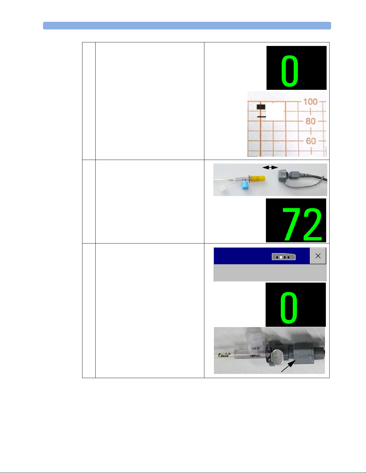
3 The IUP numeric replaces the Toco and
shows 0. The monitor is automatically
zeroed.
On a running paper trace, IUP appears
instead of Toco.
4 Connect the Koala IUP catheter to the
Koala IUP adapter cable.
IUP
FMP
IUP
IUP
5 Select the IUP numeric on the screen to
open the Setup IUP menu.
Select Zero IUP to reset the IUP back to
Zero.
While zeroing the IUP measurement in a
real situation, ensure that the transducer
(see arrow) is at the same level as the
maternal xiphoid (lower-end of the
sternum).
Setup IUP
Zero IUP
IUP
27
Page 32
5 Standard Functions Fetal Measurements
Cordless Transducer System - Avalon CTS
Monitoring Mode
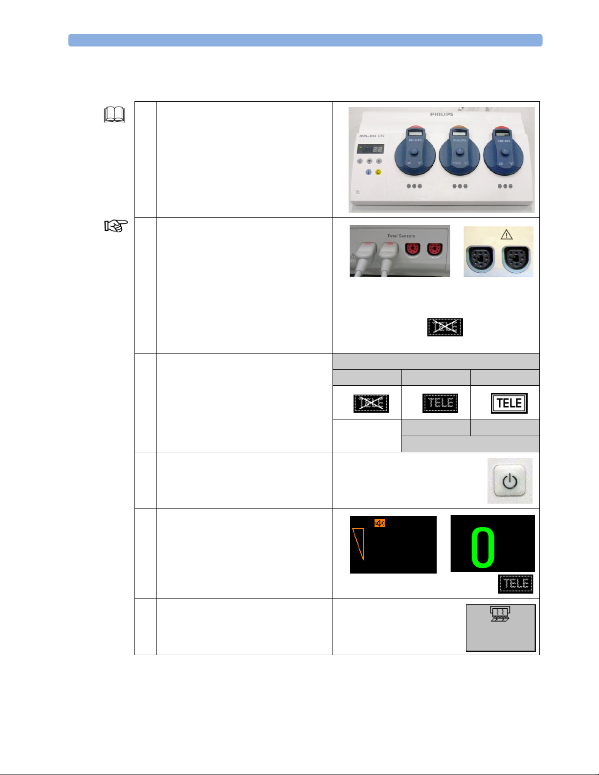
1 This is not a training section for the Avalon
CTS Cordless Fetal Transducer System.
Before monitoring patients, it is essential to
have a comprehensive understanding of
this device (see IfU of the Avalon CTS Cordless Fetal Transducer System).
2 Connect Avalon CTS via the M2731-
60001 interface cable (with red connector)
or via the M2732-60001 interface cable
(with black connector - for FM 40/50
only) to the fetal monitor.
All wired transducers can remain plugged
into the fetal sensor sockets.
Do not switch the Avalon CTS on. Check
the Avalon CTS indicator on the fetal
monitor screen.
3 When the monitor recognizes an Avalon
CTS interface cable M2731-60001 (red
connector) or M2732-60001 (black
connector, for rear connection on FM40/
FM50 only), it provides confirmation by
showing the following status indicator in
the lower right-hand corner of the screen.
4 Press the Power switch to turn on the
Avalon CTS.
Tele
FM 20/30
FM 40/50
FM 40/50
only
Avalon CTS Cordless Fetal Transducer System
Off On On
Ready Active
Wireless Transducer
28
5 On the fetal monitor screen, the wired
transducers are still active and the Avalon
CTS indicator displays an active base
station, and that all cordless transducers are
currently inactive.
6 Switch on the recorder to document the
next steps.
FHR1
Toco
Start/
Stop
Page 33
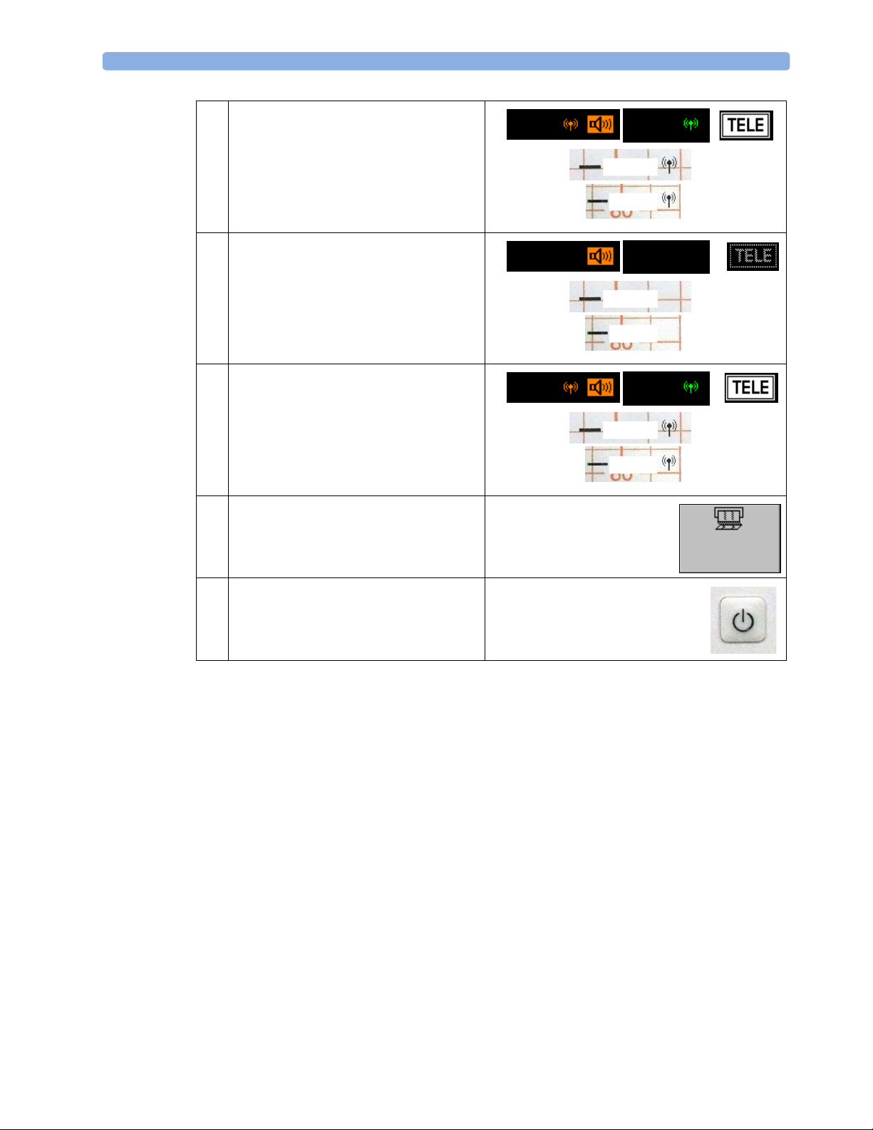
Fetal Measurements 5 Standard Functions
7 Take out at least one of the transducers to
activate the wireless mode and check the
changes on the
• fetal monitor screen
• paper trace
8 Bring the wireless transducers out of range
of the base station and check the changes
on the
• fetal monitor screen
• paper trace
9 Bring the wireless transducers back into
range of the base station and check the
changes again.
Observe the FMP indicator on the paper
trace.
10 Switch off the recorder.
FHR1
FHR1
FHR1
Toco
FHR1
Toco
Toco
FHR1
Toco
Toco
FHR1
Toco
11 Switch off the Avalon CTS.
Start/
Stop
29
Page 34
5 Standard Functions Fetal Measurements
Monitoring Twins and Triplets
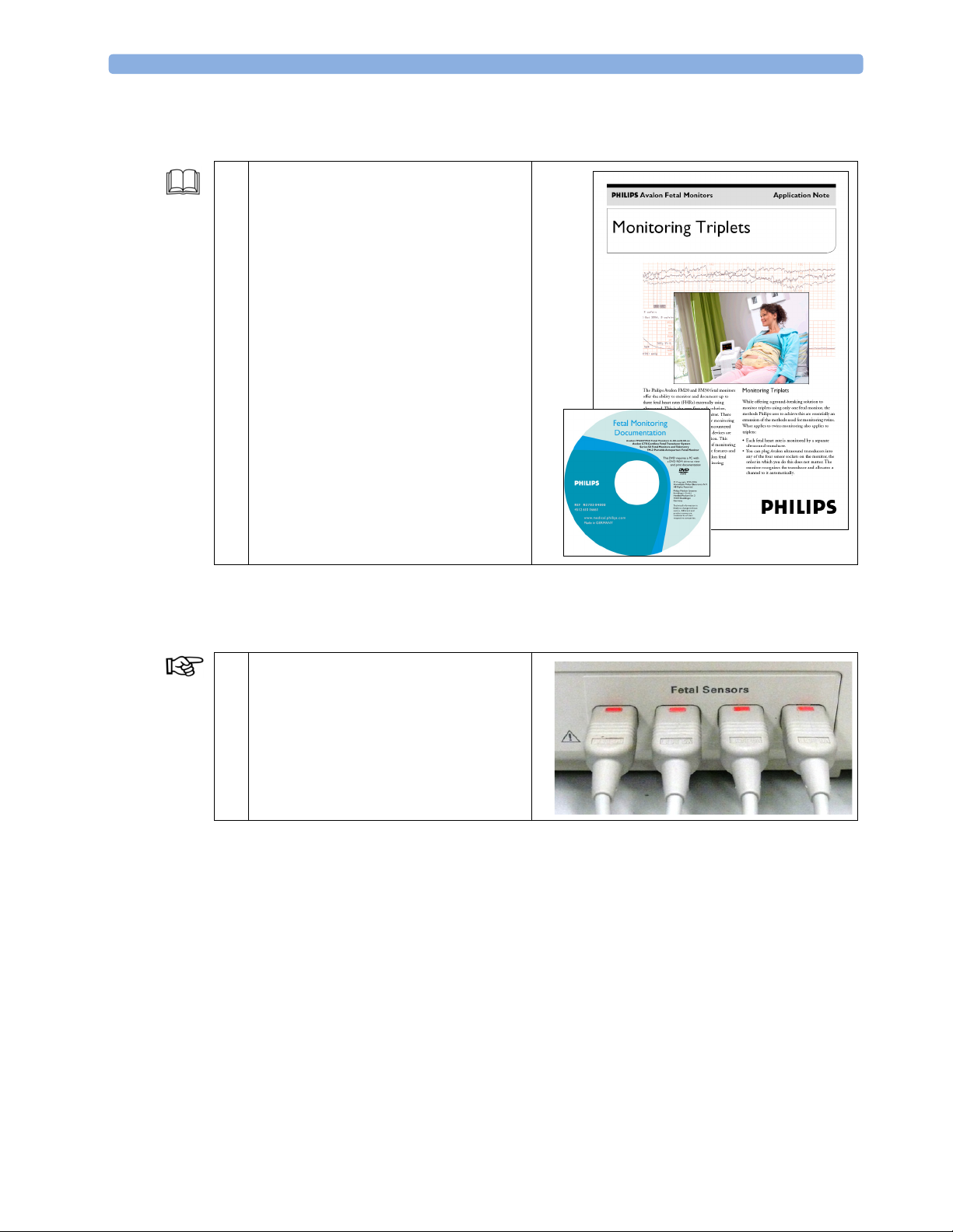
1 For detailed information about monitoring
twins and triplets, read the “Monitoring
Triplets” application note (English only) on
the “Fetal Monitor Documentation” DVD.
Demo Mode Since it is not possible to obtain real twin or triple data during this training, enter the monitor’s Demo
mode (see “Activating Demo Mode” on page 2)
2 Depending on the equipment you are
using, connect the sensors to a free sensor
socket of the fetal monitor. In our example,
one Toco and three US sensors will be
used.
.
30
Page 35
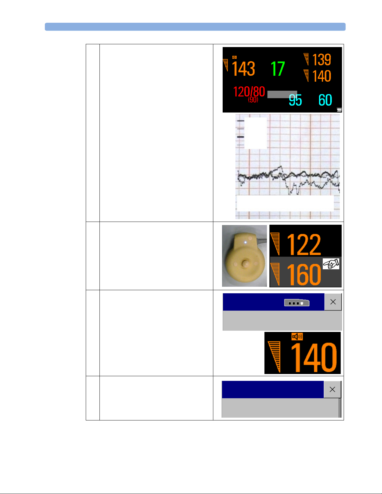
Fetal Measurements 5 Standard Functions
3 The monitor displays the labels of the three
FHRs and the Toco on the screen.
On the paper trace, the three FHR traces
are recorded in different grey scales and line
thicknesses.
The Demo mode generates values for all
measurements, also for the NBP and SpO
measurement (even when they are
unplugged).
4 Select a FHR numeric on the screen and
check the bright, blue finder LED on the
corresponding transducer.
FHR1
NBP Pulse 60 Auto 16:30
2
Toco
FHR2
FHR3
DEMO
FHR1
FHR2
FHR3
Pulse
Demo Data
FHR2
5 In the Setup FHR3 menu, select Select
Audio to hear the fetal heart beat of
FHR3. It may take a few seconds for the
audio source symbol to appear on the
screen.
Be aware that Demo mode does not
provide any audio signal of the FHRs.
6To switch On trace separation, open the
Main Setup menu. There, select Fetal
Recorder to open the Fetal Recorder
menu.
FHR3
Setup FHR3
Select Audio
FHR3
Main Setup
Fetal Recorder
31
Page 36
5 Standard Functions Maternal Measurements
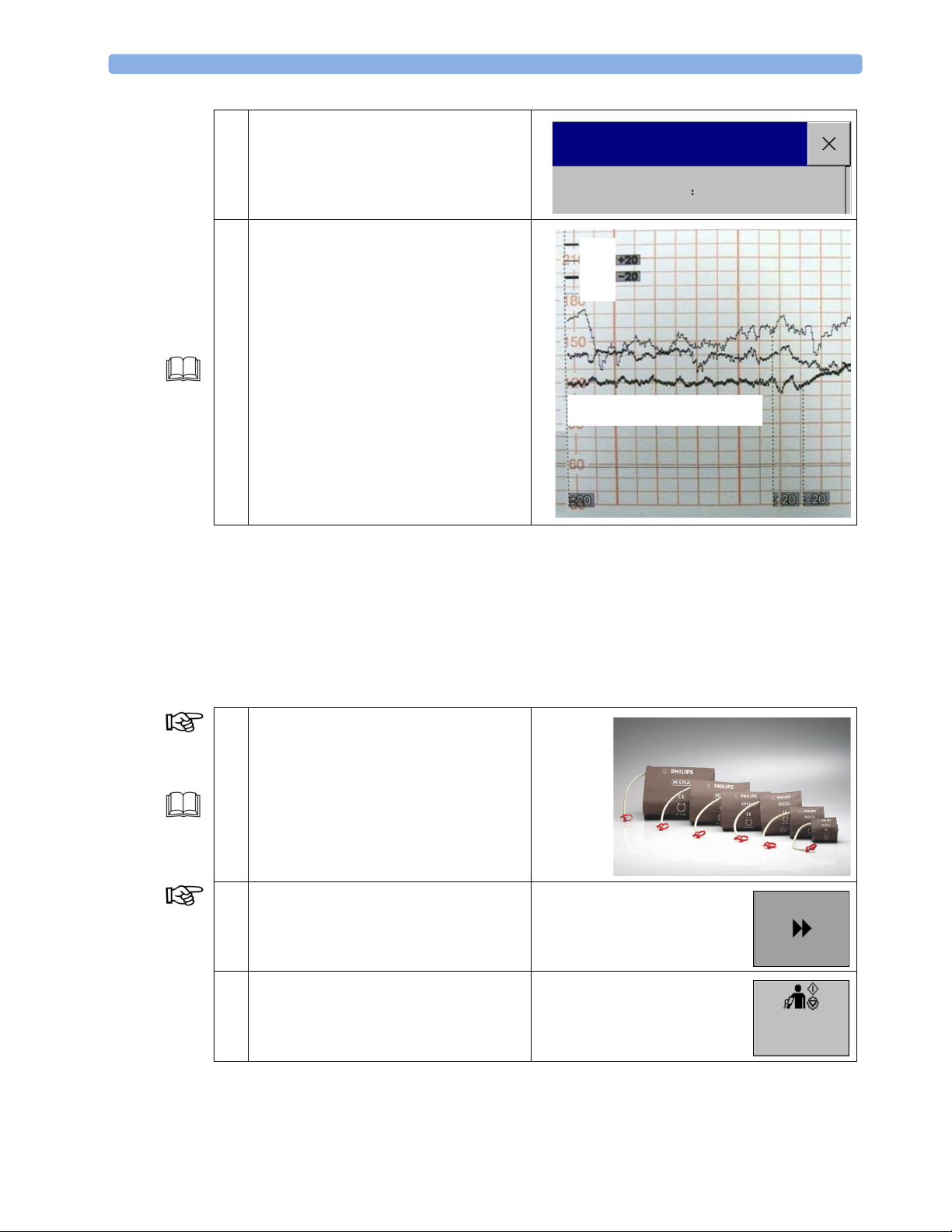
7 In the Fetal Recorder menu, select Trace
Separation to toggle between On and
Off.
Fetal Recorder
8 FHR1 trace stays where it is.
FHR2 trace is shifted up by 20 bmp (it is
recorded 20 bpm higher than it really is).
FHR3 trace is shifted down by 20 bmp (it
is recorded 20 bpm lower than it really is).
For further information about the two
different methods (Standard or Classic) for
determining the trace separation, see
“Monitoring Twins FHRs” in the IfU.
Exit Demo mode (see “Exiting Demo
Mode” on page 2).
Maternal Measurements
In a fetal monitor, monitoring of the fetus is the primary task. Nevertheless, maternal measurements
are becoming increasingly important.
Trace Separation
FHR1
FHR2
FHR3
Pulse
Demo Data
On
Monitoring Noninvasive Blood Pressure (NBP)
Monitoring Mode
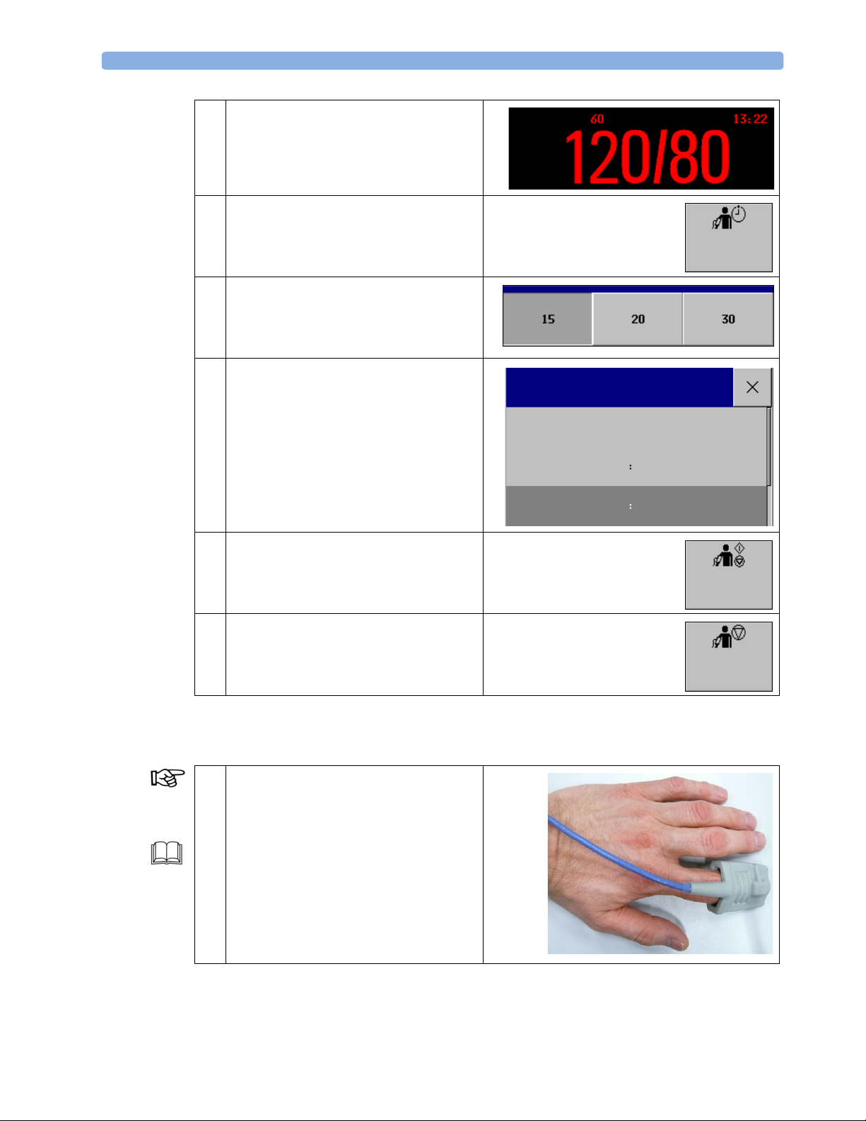
1 Attach a correctly sized cuff to your arm
and connect the NBP tubing to the
monitor.
For further information about the correct
placement of the NBP cuff, see
“Monitoring Noninvasive Blood Pressure Preparing to Measure Noninvasive Blood
Pressure” in the IfU.
2 With the arrow scroll button, change to the
second set of SmartKeys.
3 To start an NBP measurement, select the
NBP Start/Stop SmartKey.
Start/
Stop
32
Page 37
Maternal Measurements 5 Standard Functions
4 As soon as the measurement is finished, the
NBP values together with the pulse from
NBP, and the timestamp are displayed on
the screen.
5 Select the Repeat Time SmartKey to
open the Pop-up keys list.
6 Select the 30 minutes pop-up key to
change the repetition time to 30 minutes.
7 Select the NBP numeric field on the screen
to open the Setup NBP menu. In the Setup
NBP menu, select Auto/Manual to
switch to the automatic series mode.
Pulse
NBP
Setup NBP
Start/Stop
Repetition Time 30 min
Auto/Manual Auto
Man
Repeat
Time
8 To start an NBP automatic series
measurement, select the NBP Start/
Stop SmartKey.
9 To stop the automatic measurement, select
the NBP Stop All SmartKey.
Monitoring SpO2 and Pulse Rate
Monitoring Mode
1 Attach a correctly sized SpO
finger and connect the SpO
monitor.
For further information about the correct
application of the SpO
“Monitoring SpO
” in the IfU.
2
sensor to your
2
cable to the
2
sensor, see
2
Start/
Stop
Stop
All
33
Page 38
5 Standard Functions Maternal Measurements
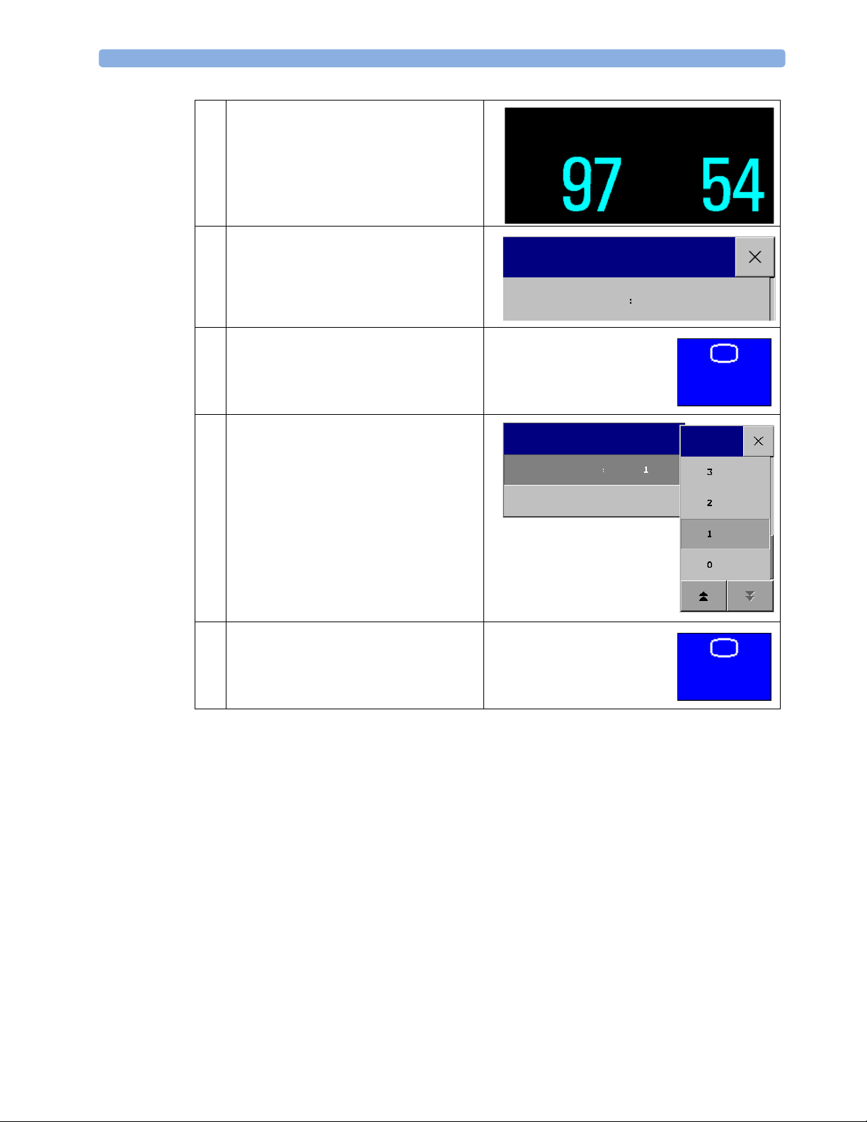
2 The screen displays the SpO2 numeric and
the pulse value, derived from SpO
Select the SpO
menu.
SpO
2
3 In the Setup SpO
numeric to open the Setup
2
menu, select Tone
2
.
2
Modulation to toggle between Yes
(for on) and No (for off).
If tone modulation is on, the QRS tone
pitch lowers when the SpO
level drops.
2
4 Select the Main Screen SmartKey to
return to the Main Screen.
5 Select the Pulse numeric to open the Setup
Pulse (SpO
In the Setup Pulse SpO
) menu.
2
, select QRS
2
Volume and change the QRS tone
volume.
SpO
2
Setup SpO
Tone Modulation
Setup Pulse (SpO2)
QRS Volume
Pulse
2
Yes
Main
Screen
6 Select the Main Screen SmartKey to
return to the Main Screen.
Main
Screen
34
Page 39
Maternal Measurements 5 Standard Functions
Cross-Channel Verification
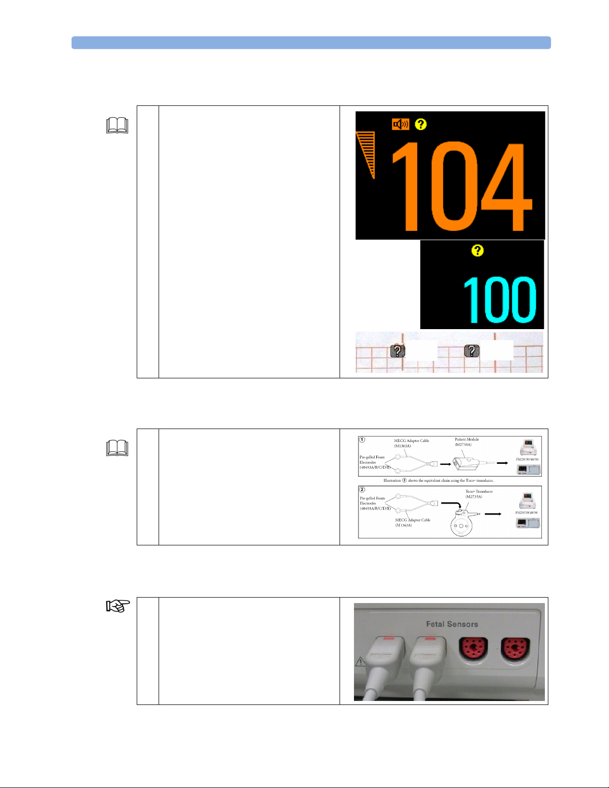
1 To reduce the probability of mistaking the
MHR for FHR, it is recommended that
you monitor both maternal and fetal heart
rates. The monitor’s cross-channel
verification (CCV) facility can help by
automatically detecting when the same
heart rate is being recorded by different
transducers. When the MHR and FHR are
being monitored, CCV will alert you
within approximately one minute when the
values are the same.
Monitoring MECG
FHR1
FHR1
Pulse
Pulse
FHR1
Pulse
1 Prepare for MECG monitoring as described
in the IfU (see “Monitoring Maternal
Heart / Pulse Rate” in the IfU).
Demo Mode Since it is not possible to obtain real MECG data during this training, enter the monitor’s Demo mode
(see “Activating Demo Mode” on page 2).
The standard procedures in use in your facility determine the appropriate sequence of actions.
2 Depending on the equipment you are
+
using, ensure that either the Toco
transducer or the patient module is
connected to a free sensor socket of the fetal
monitor.
35
Page 40
5 Standard Functions Maternal Measurements
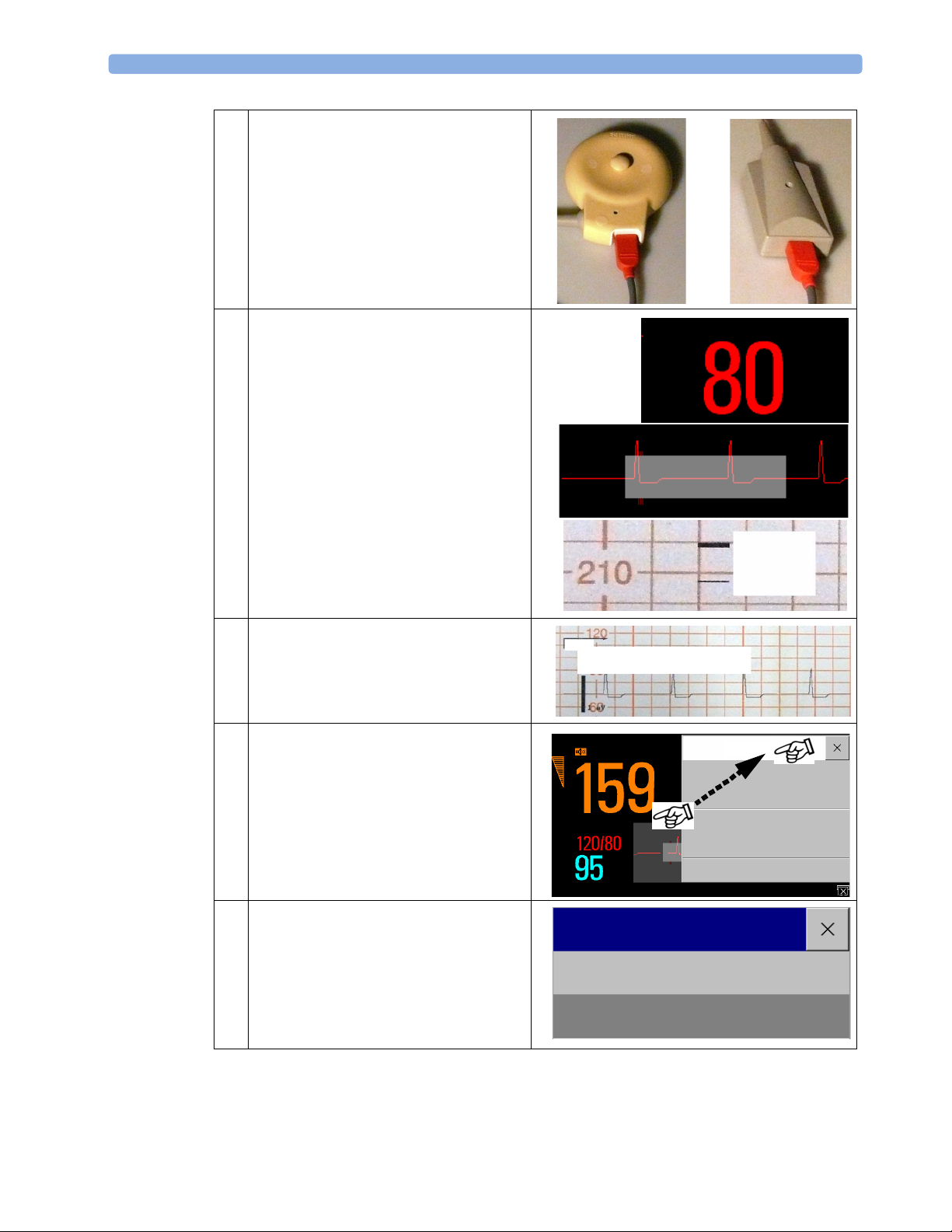
2 Connect the red connector plug of the
+
ECG cable to either the Toco
transducer
or the patient module.
3 The monitor displays the HR numeric
together with a running ECG wave.
On the paper trace, HR is recorded.
In Demo mode, the monitor generates
values for all measurements, also for NBP
and SpO
measurement, even when they
2
are unplugged.
4 Select the ECG waveform to open the ECG
Wave menu.
Select Start ECG Wave to print the
MECG wave onto the trace paper.
5 Move the ECG Wave menu to the right
side of the screen:
Touch the title bar of the ECG Wave menu
and keep your finger on the title. Drag the
menu window to the right side of the
display. Take your finger off the screen to
place the window in this position.
ECG
ECG
Demo Data
FHR1
NBP Pulse 60 Man
HR
1mV
ECG
DEMO
ECG Wave
Size Up
Size Down
Start ECG Wave
Setup ECG
D
Global Speed
FHR1
HR
25 mm/sec
36
6 In the ECG Wave menu, select Size Up
and Size Down to increase and decrease
the QRS signal of the ECG wave.
Observe the size changes on the wave.
Exit Demo mode (see “Exiting Demo
Mode” on page 2).
ECG Wave
Size Up
Size Down
Page 41
General Parameters 5 Standard Functions
General Parameters
Entering Notes
Monitoring Mode
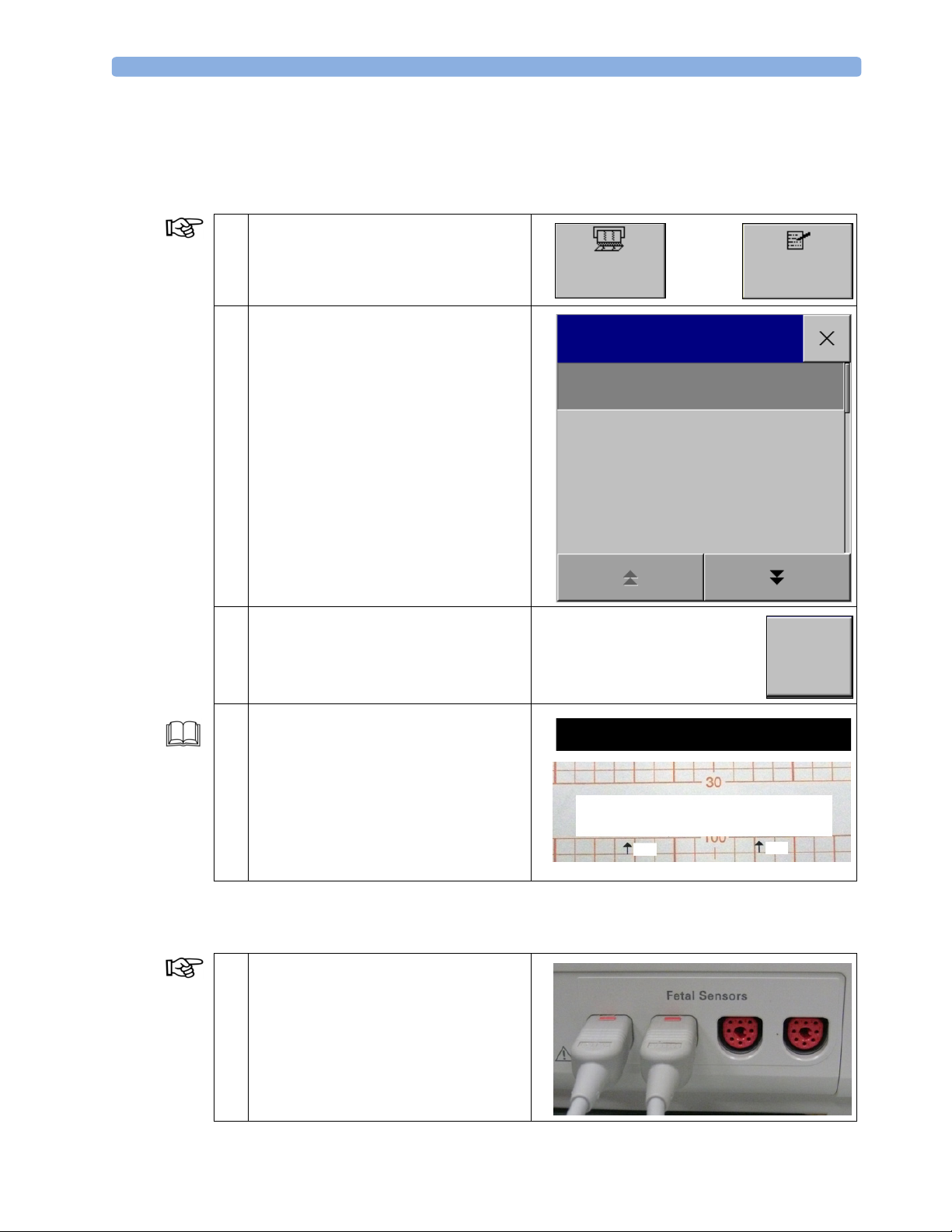
1 To switch on the recorder, press the
Start/Stop SmartKey.
Select the Enter Notes SmartKey to
open the Enter Notes menu.
2 In the Enter Notes menu, scroll, if
necessary, then select the note you wish to
enter.
Start/
Stop
Enter Note
Patient Repositioned
Vaginal Examination
MD Notified
Enter
Notes
3 Select Confirm to enter the note.
4 The note is then shown in the status line of
the display and is annotated on the fetal
trace.
Stop the recorder.
For further information about entering
notes, especially if you try to enter more
than four notes at one time, see “Basic
Operation - Entering Notes” in the IfU.
Marking an Event
Monitoring Mode
1 Connect the remote event marker to any
free fetal sensor socket.
Sitting
Confirm
Note: Patient Repositioned
Vaginal Examination
Patient Repositioned
FMP
Sitting
MD Notified
FMP
Start the recorder.
37
Page 42
5 Standard Functions General Parameters
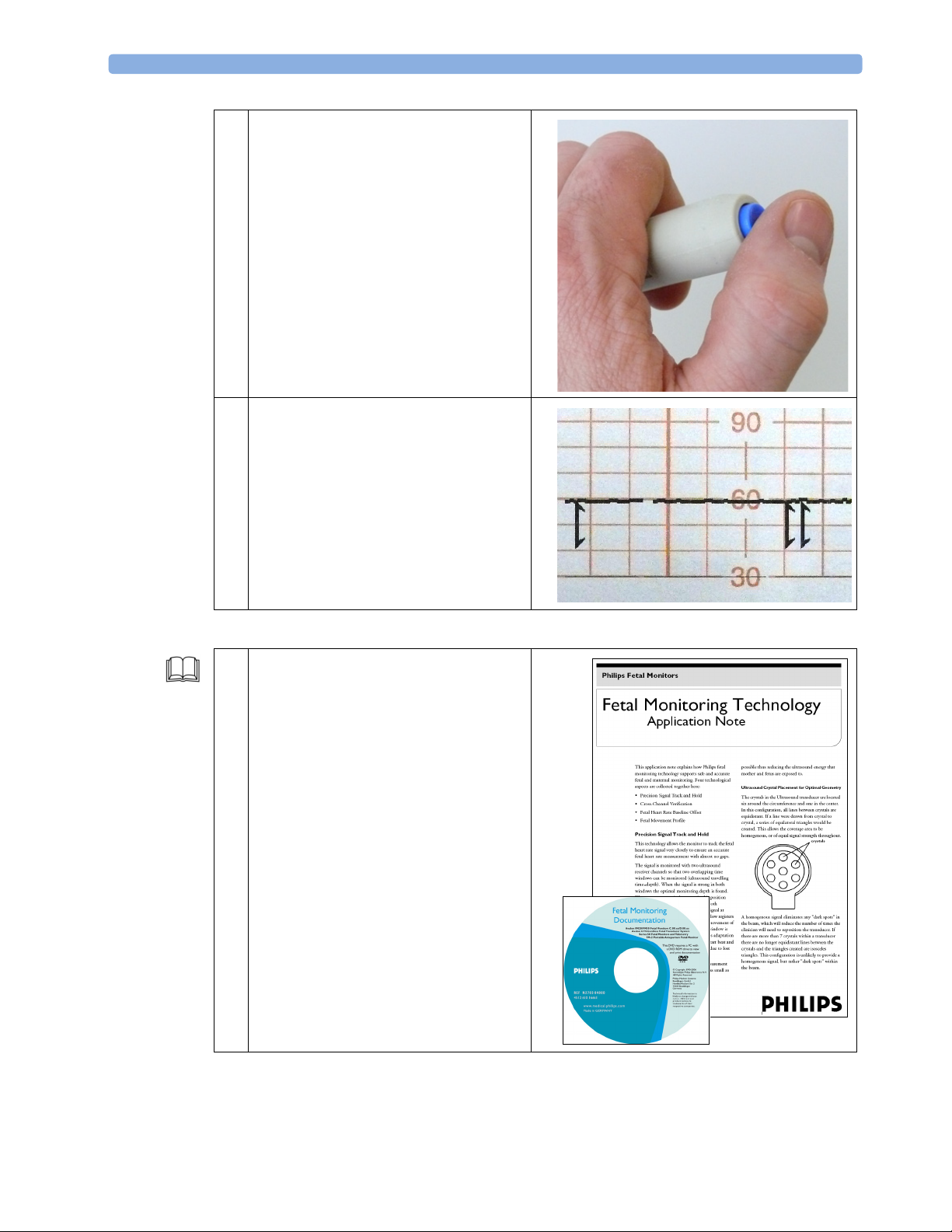
2 Press the button on the remote event
marker.
To set a marker directly on the monitor, it
is possible to configure a Set Marker
SmartKey in the monitor’s Configuration
mode.
3 A small arrow is printed on the heart rate
scale on the trace paper.
Stop the recorder.
For detailed information about fetal
monitoring technology, read the “Fetal
Monitoring Technology” application note
(English only) on the “Fetal Monitor
Documentation” DVD.
This application note explains how Philips
fetal monitoring technology supports safe
and accurate fetal and maternal monitoring.
Four technological aspects are presented
together here:
• Precision Signal Track and Hold
• Cross-Channel Verification
•Fetal Heart Rate Baseline Offset
• Fetal Movement Profile.
38
Page 43
General Parameters 5 Standard Functions
Admitting, Transferring and Discharging Patients
In this section you will learn about patient data management in your monitor. With regard to the
training aspect, you will go through different steps which do not correspond exactly with your daily
work. Some of the steps are not the fastest procedure to perform a task, they just show you an
additional way.
To prevent additional entries in your OB TraceVue’s database, you will use the Quick Admit
procedure, where you can delete your training patients, instead of using real patient names. If you have
a unique test patient in your OB TraceVue system, it is also possible to use this patient.
From these steps, your hospital will develop the best method for managing your patients’ data.
Standalone Fetal Monitor
A standalone fetal monitor is not connected to OB TraceVue or another documentation system.
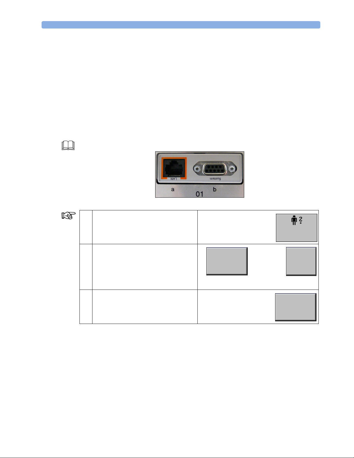
Slot 01(a/b) is unplugged.
Monitoring Mode
1 Select the Admit/Dischrg SmartKey
to open the Patient Demographics menu.
2 To trigger a new patient data episode for
Stored Data Recording, select the
Dischrge Patient pop-up key of the
fetal monitor and then Confirm. This
also activates the user default settings in the
fetal monitor.
3 Select Admit Patient to open the on-
screen keyboard, which prompts for the
Last Name.
Dischrge
Patient
Admit/
Dischrge
Confirm
Admit
Patient
39
Page 44
5 Standard Functions General Parameters
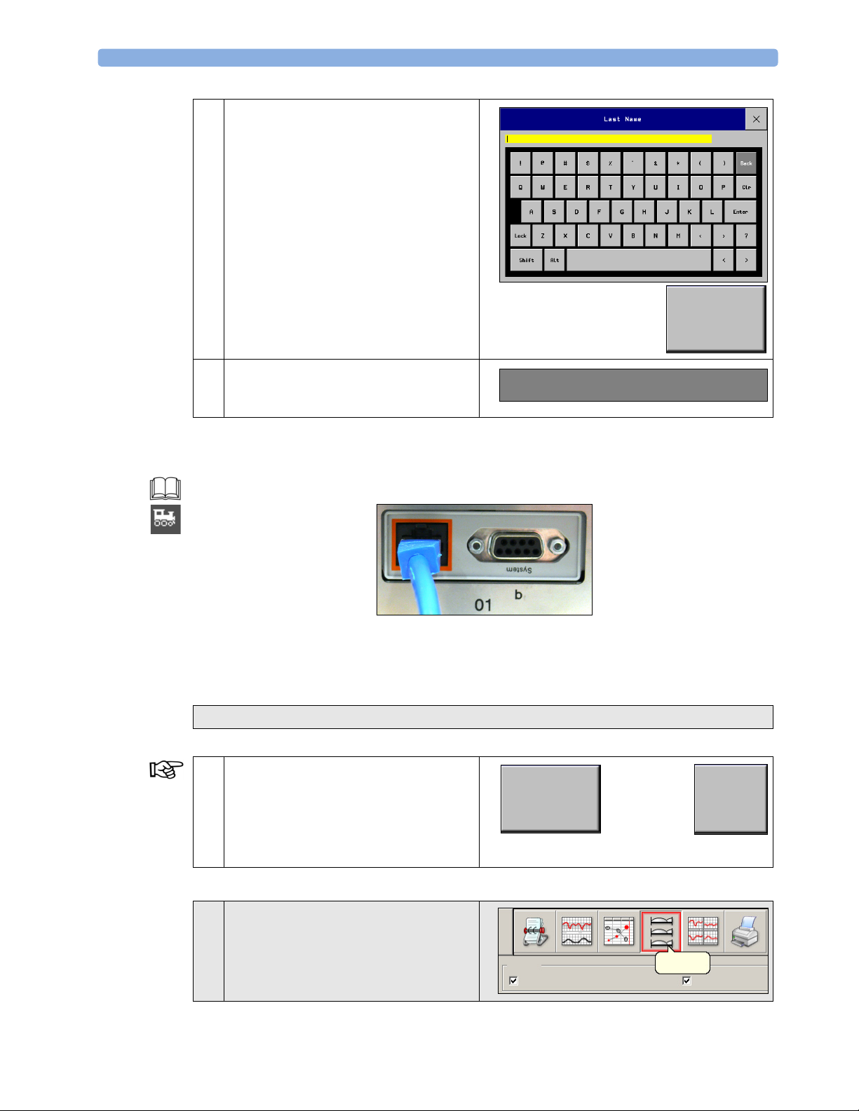
4 Enter the patient information; select each
field, using the on-screen keyboard.
Type in the information and select Enter.
•Selecting Enter moves you
consecutively through all fields.
• To skip a field, select Enter without
entering data.
When you have entered all required data,
select Confirm to admit the patient.
Confirm
5 The name of the patient appears in the
patient identification field on the fetal
monitor.
Fetal Monitor connected to OB TraceVue via LAN
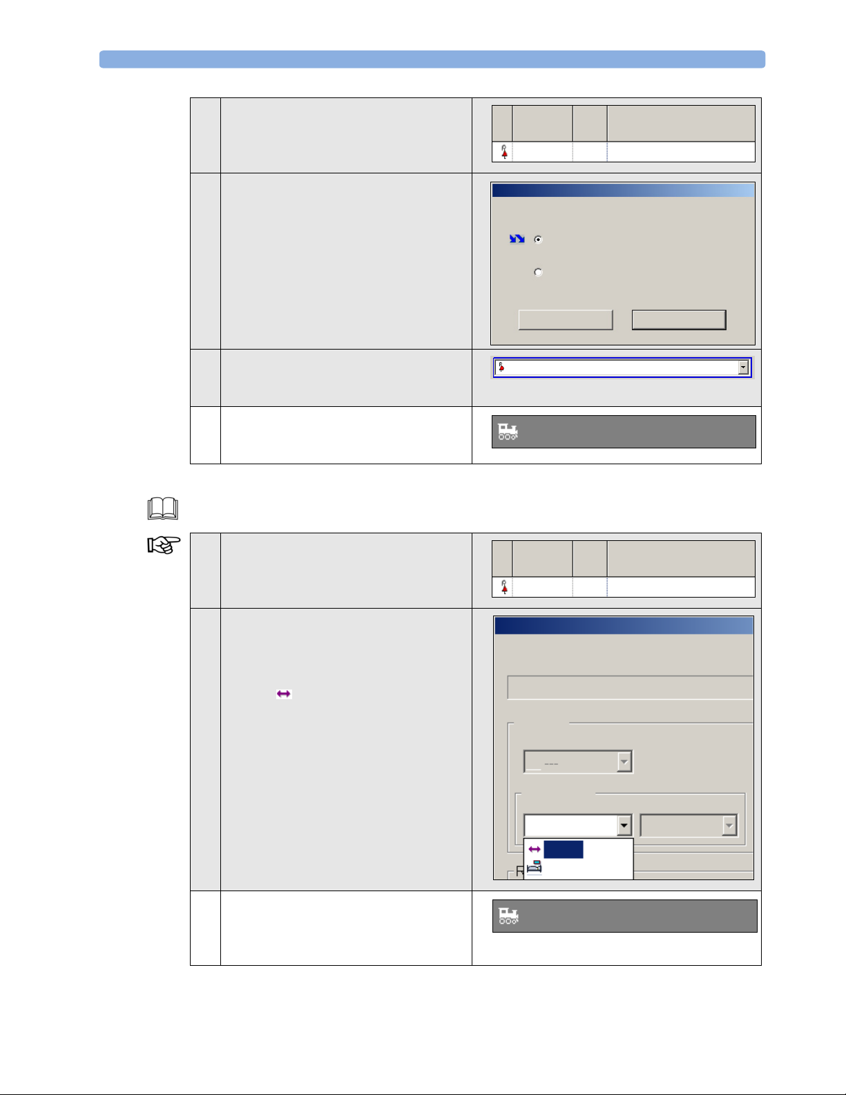
Your fetal monitor is connected to OB TraceVue via a LAN connection. The LAN cable is connected
to Slot 01 (labeled a/LAN) of the fetal monitor.
When the monitor is connected to an OB TraceVue system over a LAN connection, the OB TraceVue
system acts as the “master” over patient demographic data. It is not possible to admit a patient on the
fetal monitor. A patient discharge on the monitor is possible and will be reflected on the OB TraceVue
system.
All tasks in shaded rows refer to OB TraceVue.
Monitoring Mode Discharge Patient
1 To trigger a new patient data episode for
Stored Data Recording, select the
Dischrge Patient pop-up key of the
fetal monitor and then Confirm. This
also activates the user default settings in the
fetal monitor.
Dischrge
Patient
Doe, Jane
Confirm
40
Quick Admit in OB TraceVue
2 Select the icon with the beds to open the
Chalkboard. Make sure you have set the
check marks to include Departmental
and Empty Beds.
Include
Departmental
Chalkboard
Empty Beds
Page 45
General Parameters 5 Standard Functions
3 Select the bed location of your monitor to
open the bed02 NO ARCHIVING
menu.
4 In the Quick Admit menu, check
Bed Phys Patient Name
bed02 NO ARCHIVING
bed02 NO ARCHIVING
Convert to Quick Admit and press
the OK button.
If you have a unique test patient in your
OB TraceVue system, it is also possible to
admit this patient at the Search/Identify
Convert to Quick Admit
Remove this episode
Patient screen of OB TraceVue.
CancelOK
5 OB TraceVue automatically generates a
temporary patient ID using Time and Date
bed02
9:54:21 11/10/2008
in place of a name.
6 After a few seconds, the temporary patient
ID appears in the Main Name area on the
9:54:21 11/10/200,
fetal monitor.
Transfer in OB TraceVue
When the monitor is connected to an OB TraceVue system, perform pending transfers before
switching off the monitor.
7 Select the bed location again to open the
Patient Transfer menu.
8 Enter the bed list in the Departmental
field.
To transfer the patient to the
Transfer Location, select the bed
with the -symbol. The name of the
Transfer Location depends on your
configuration (in this case ---). Confirm
with OK.
9 The fetal monitor reflects this transfer as a
patient discharge on the monitor. As long
as no new patient is admitted,
NO ARCHIVING in OB TraceVue occurs.
Bed Phys Patient Name
bed02 9:54:21 11/10/2008
bed02: 9:45:21 11/10/2008
Patient Transfer
9:54:21 11/10/2008
Location
Unit
Departmental
---
bed03
NO ARCHIVING,
41
Page 46
5 Standard Functions General Parameters
Transfer back in OB TraceVue
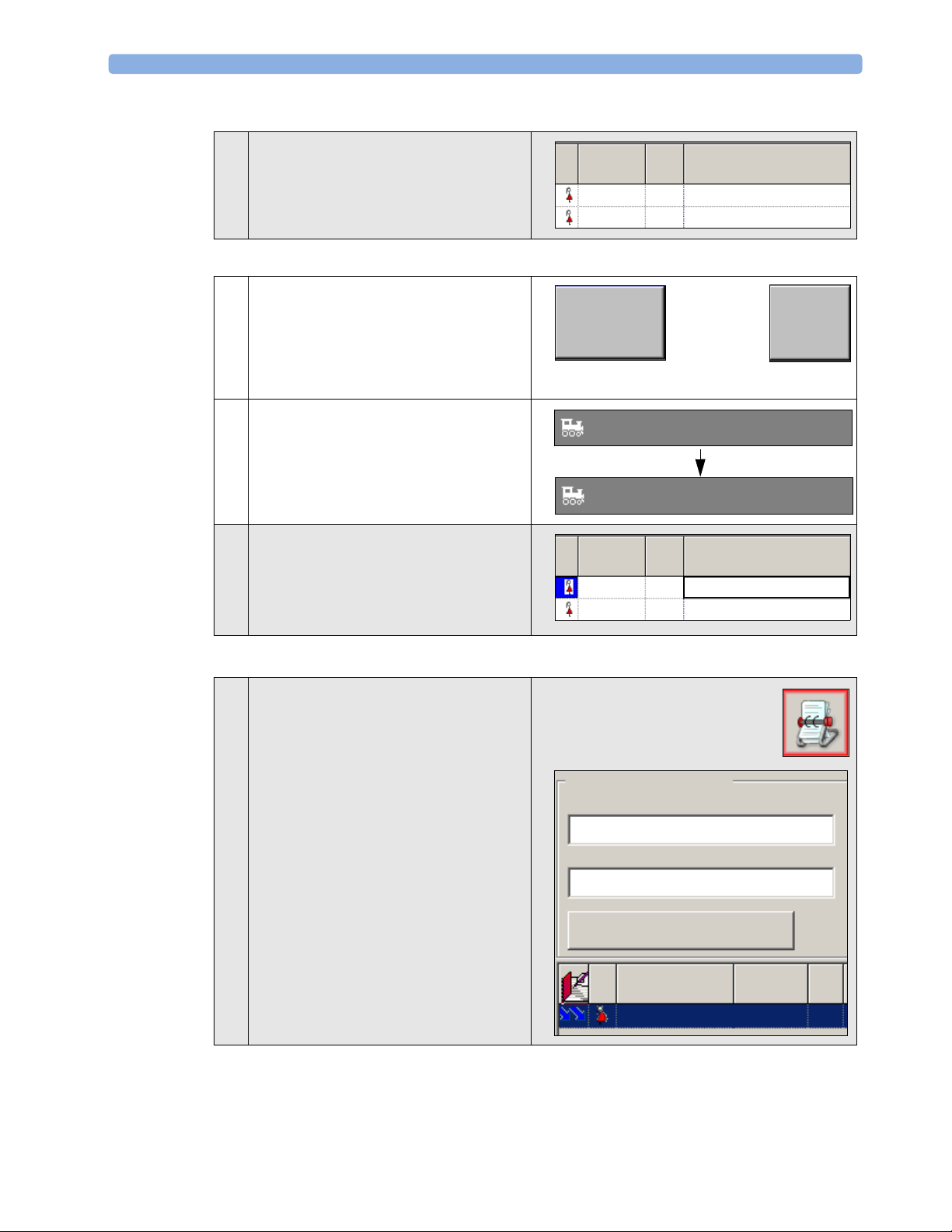
10 Transfer your patient from the Transfer
Location back to the fetal monitor and
review the changes on the fetal monitor.
Discharge in the Fetal Monitor
Bed Phys Patient Name
--- 9:54:21 11/10/2008
bed02 NO ARCHIVING
11 To trigger a new patient data episode for
Stored Data Recording, select the
Dischrge Patient pop-up key of the
Dischrge
Patient
Confirm
fetal monitor and then Confirm. This
also activates the user default settings in the
fetal monitor.
12 The fetal monitor indicates that there is no
patient admitted and NO ARCHIVING in
No Patient Admitted
OB TraceVue occurs.
NO ARCHIVING,
13 The patient in OB TraceVue is
automatically transferred back to the
Transfer Location.
Select the patient’s Name to mark the
patient.
Delete Patient in OB TraceVue
14 To open the Search/Identify Patient screen
of OB TraceVue, select the Identify/
Search Patient icon.
Bed Phys Patient Name
---
bed02 NO ARCHIVING
Patient Identification
Last Name
9:54:21 11/10/2008
Last Name
9:54:21 11/10/2008
Clear
First Na
M.I.
42
9:54:21 11/10/
Page 47
General Parameters 5 Standard Functions
15 On the Search/Identify Patient screen,
select the Delete Patient pop-up key
Delete Patient
and then confirm with Yes.
Please Confirm...
Are you sure you want to delete the temporary patient:’9:54:21 11/10/2008’?
Yes No
Fetal Monitor connected to OB TraceVue via RS232
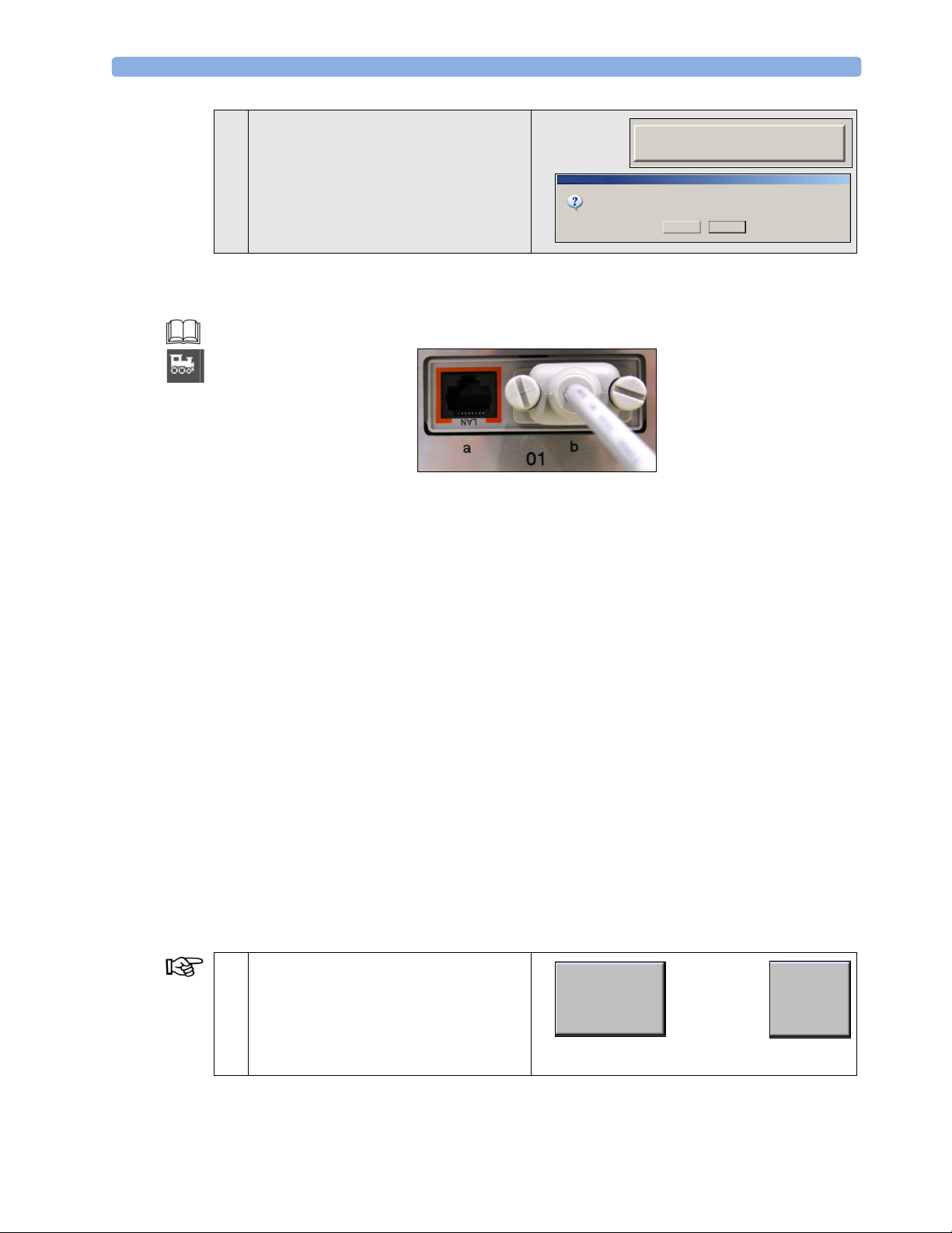
Your fetal monitor is connected to OB TraceVue via an RS232 connection. The RS232 cable is
connected to Slot 01 (labeled b/System) of the fetal monitor.
When the monitor is connected to an OB TraceVue system over an RS232 connection, the
OB TraceVue system has no control over the monitor’s patient admission and discharge functions.
• A discharge in the fetal monitor clears any previous patient data and replaces any user settings with
user defaults.
• A transfer in OB TraceVue changes the patient’s name in the monitor, but does not provide a real
patient’s discharge in the fetal monitor. Patient data and user settings remain the same.
• You must discharge a patient in the fetal monitor to trigger a new patient data episode.
The recommended patient discharge and admission procedure is:
1. Discharge the previous patient in the fetal monitor.
2. Transfer the previous patient in OB TraceVue.
3. Admit the following patient in OB TraceVue.
• Patient details (first name, last name, bed) is transferred to the fetal monitor.
• Patient details are shown on the fetal monitor screen and on the trace.
You must not change the patient name or medical record number in the fetal monitor. Although this
procedure would display patient details on the fetal monitor screen and on the paper trace, they would
not be transferred to OB TraceVue.
Monitoring Mode For a fetal monitor connected to OB TraceVue via RS232, the following admission and discharge is
recommended:
Discharge Patient
1 To trigger a new patient data episode for
Stored Data Recording, select the
Dischrge Patient pop-up key of the
Dischrge
Patient
Confirm
fetal monitor and then Confirm. This
also activates the user default settings in the
fetal monitor.
43
Page 48
5 Standard Functions General Parameters
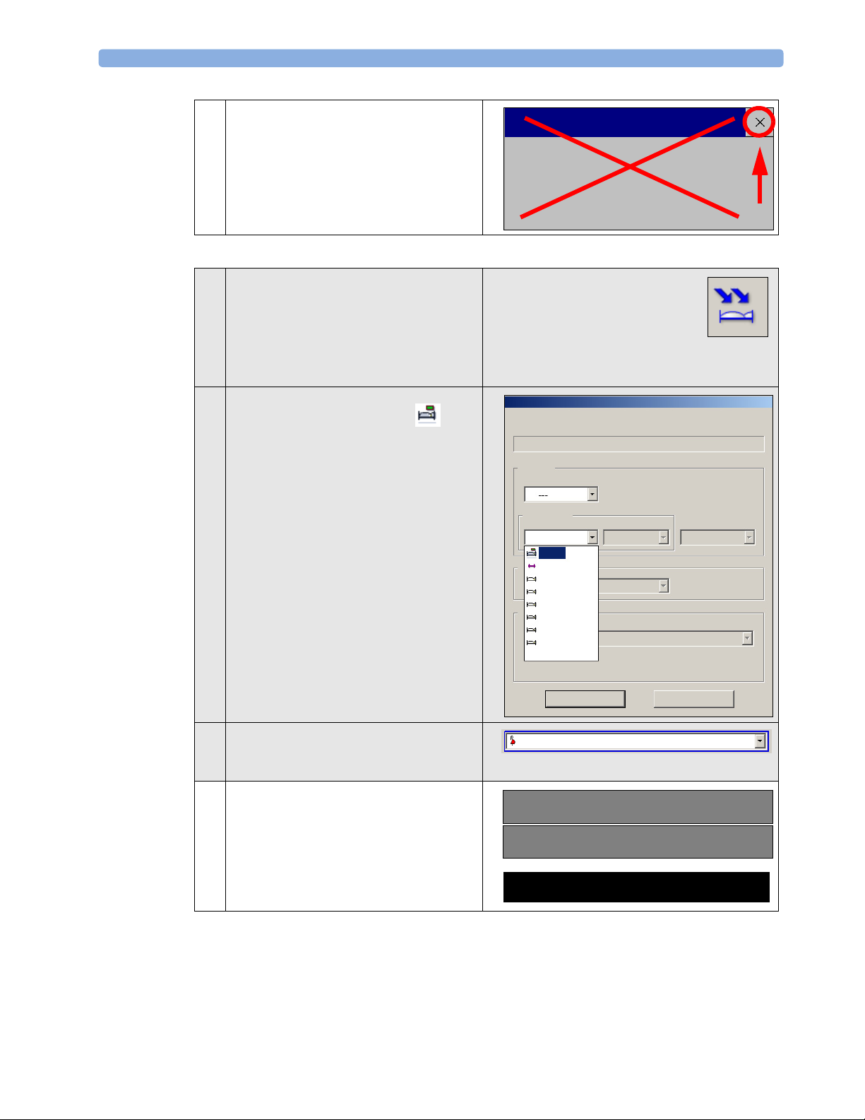
2 You must not admit the patient in the fetal
monitor.
Close the Patient Demographics window.
Quick Admit in OB TraceVue
3 With the Quick Admit button, open the
Quick Admit menu.
If you have a unique test patient in your
OB TraceVue system, it is also possible to
admit this patient at the Search/Identify
Patient screen of OB TraceVue.
4
Select the bed location with the symbol to assign your patient to a bed with
a fetal monitor.
Select OK to quick admit your patient.
Patient Demographics
Last Name
First Name
MRN
Location
Unit
Departmental
: No Patient admitted
:
:
Quick Admit
Create Temporary Patient
5 OB TraceVue automatically generates a
temporary patient ID using time and date
in place of a name.
6 After a few seconds, the temporary patient
ID appears in the Main Name area on the
fetal monitor.
The status line shows the following prompt
message:
bed01
--bed02
bed03
bed04
bed05
bed06
cafe
bed01
OK
9:54:21 11/10/2008
Cancel
9_54_21 11/10/2008
bed01
Note from System:{*bed01:9_54_21 11/10/2008}
44
Page 49
General Parameters 5 Standard Functions
Transfer in OB TraceVue
When the monitor is connected to an OB TraceVue system, perform pending transfers before
switching off the monitor.
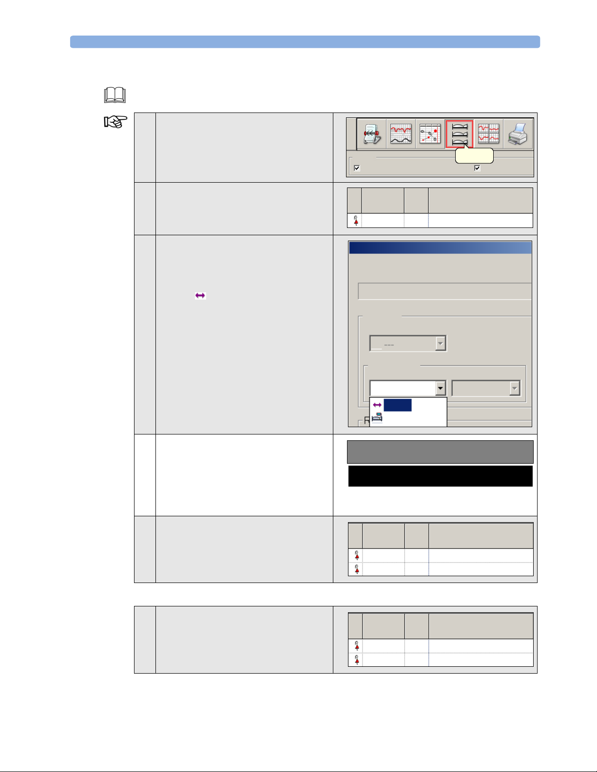
7 Select the beds icon to open the
Chalkboard. Make sure you have set the
check marks to include Departmental
and Empty Beds.
Include
Departmental
Chalkboard
Empty Beds
8 Select the bed location of your patient to
open the Patient Transfer menu.
9 Enter the bed list in the Departmental
field.
To transfer the patient to the
Transfer Location, select the bed
with the -symbol. The name of the
Transfer Location depends on your
configuration (in this case ---). Confirm
with OK.
10 After a few seconds, the name of the patient
disappears in the patient identification field
on the fetal monitor, and a dash is
displayed instead.
Bed Phys Patient Name
bed01 9:54:21 11/10/2008
bed01: 9:54:21 11/10/2008
Patient Transfer
9:54:21 11/10/2008
Location
Unit
Departmental
---
bed01
-,
Note from System:{*bed01:-,}
11 The Chalkboard of OB TraceVue
reflects that your patient is in the
Transfer Location (---), and the
data of the fetal monitor from bed01 is not
archived.
Transfer back in OB TraceVue
12 Transfer your patient from the Transfer
Location back to the fetal monitor and
review the changes on the fetal monitor.
Bed Phys Patient Name
--- 9:54:21 11/10/2008
bed01 NO ARCHIVING
Bed Phys Patient Name
--- 9:54:21 11/10/2008
bed01 NO ARCHIVING
45
Page 50
5 Standard Functions General Parameters
Delete Patient in OB TraceVue
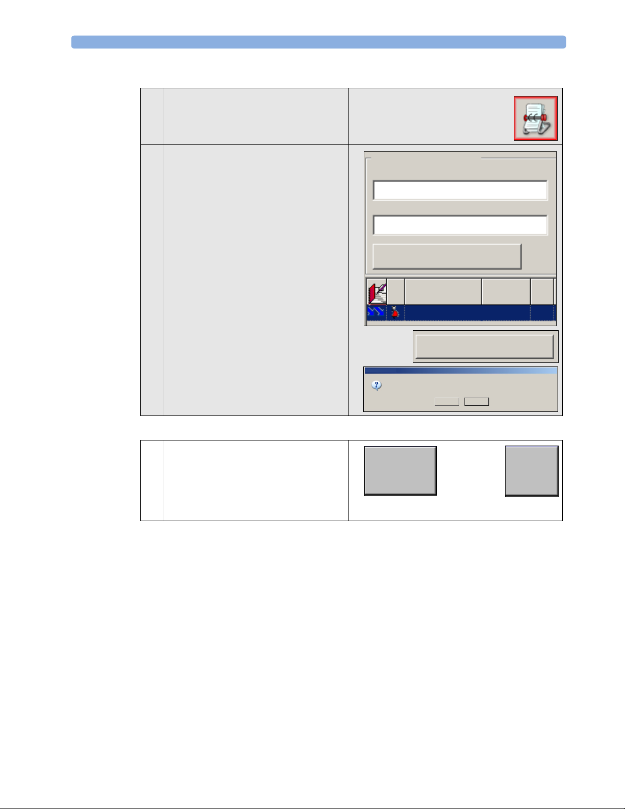
13 To open the Search/Identify Patient screen
of OB TraceVue, select the Identify/
Search Patient icon.
14 On the Search/Identify Patient screen,
select the Delete Patient pop-up key
and then confirm with Yes.
Discharge in the Fetal Monitor
15 To trigger a new patient data episode for
Stored Data Recording, select the
Dischrge Patient pop-up key of the
fetal monitor and then Confirm. This
also activates the user default settings in the
fetal monitor.
Patient Identification
Last Name
9:54:21 11/10/2008
Clear
Last Name
First Na
9:54:21 11/10/
Delete Patient
Please Confirm...
Are you sure you want to delete the temporary patient:’9:54:21 11/10/2008’?
Yes No
Dischrge
Patient
Confirm
M.I.
46
Page 51
General Parameters 5 Standard Functions
Fetal Monitor Connections
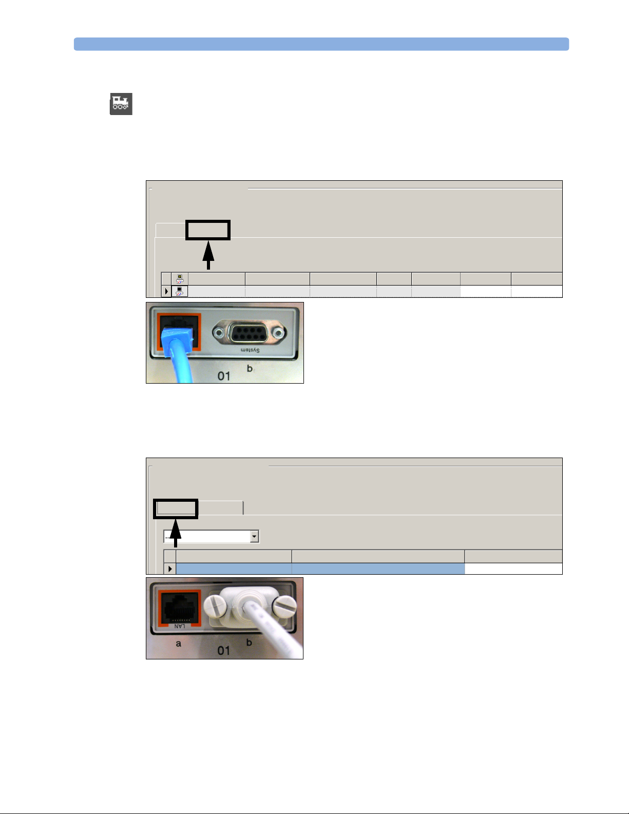
Your fetal monitor can be connected to OB TraceVue either over a LAN connection or an RS232
connection (Classic). You can look up your fetal monitor connection in OB TraceVue on the fetal
monitor port assignment page.
LAN Connection
Your fetal monitor is connected to OB TraceVue via a LAN connection (register card “Network”).
Fetal Monitor Connections
After changing a fetal monitor connection, verify that the trace appears
in the Single Patient Trace and for the expected bed.
Classic
Network
Care Unit:
Equipment Label MAC Last Activity Unit (PC) PC Name Connection Bed
Fm50 00-09-FB-0C-F2-1C connected --- PC’s name permanent bed02
The LAN cable is connected to Slot 01 (labeled a and LAN) of the fetal monitor.
RS232 Connection
Your fetal monitor is connected to OB TraceVue via an RS232 connection (register card “Classic“).
Fetal Monitor Connections
After changing a fetal monitor connection, verify that the trace appears
in the Single Patient Trace and for the expected bed.
Classic
Care Unit:
The RS232 cable is connected to Slot 01 (labeled b and System) of the fetal monitor.
Network
PC Name
PC’s Name FM is connected to
COM Port
Bed
bed01
47
Page 52
5 Standard Functions General Parameters
Connection Status Indicator
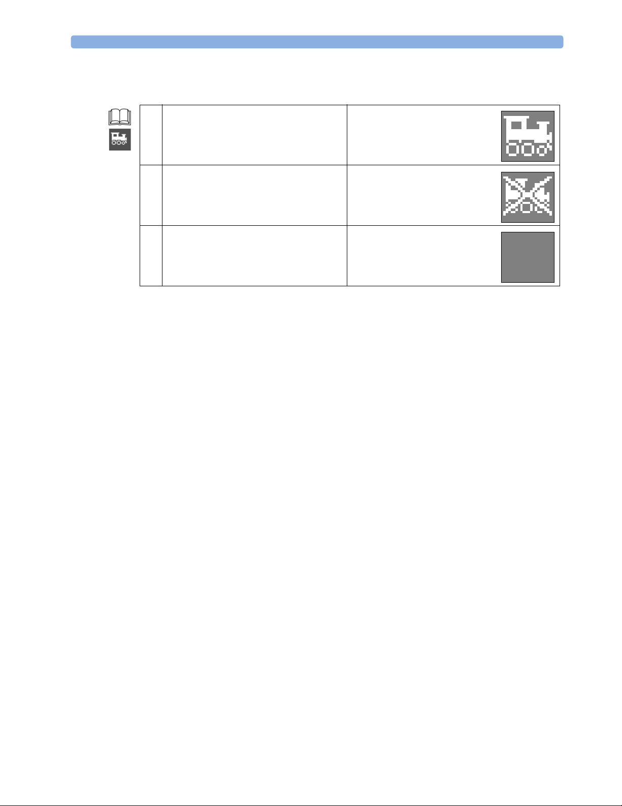
On the left-upper corner of the fetal monitor, the Connection Status Indicator is displayed.
1 The monitor is connected to an
OB TraceVue system via a LAN cable.
2 A LAN cable is connected to the monitor,
but there is no connection to an
OB TraceVue system.
3 If no indicator is shown, there is no
network connection, or the monitor is
connected to a network via an RS232
connection.
48
Page 53
Alarms
Monitoring Mode
6
6Changing Settings
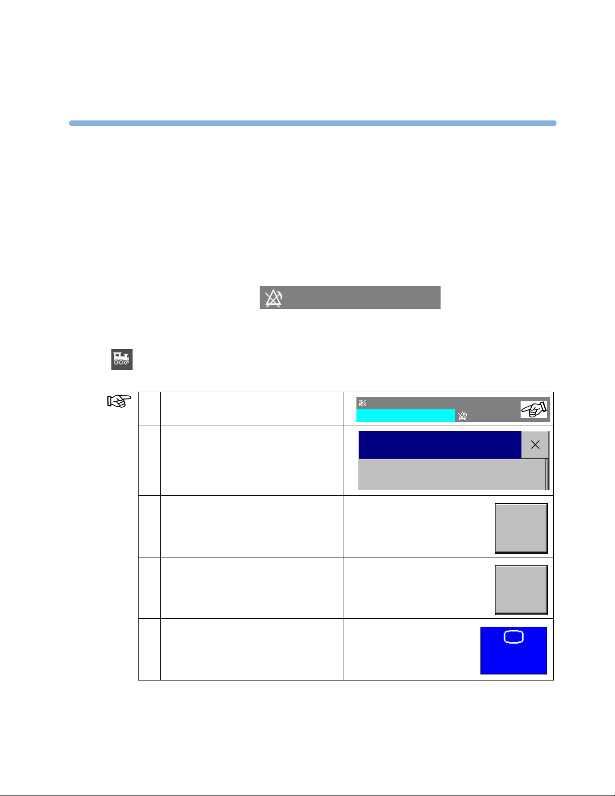
The default alarm mode is “INOP Only”. In INOP Only mode, no patient alarms are enabled or
announced.
INOP Only
For further information about alarms, especially if your default settings are changed, refer to “Alarms”
in the IfU.
Alarms are not transmitted to OB TraceVue. It is recommended to use either OB TraceVue’s alarm
capabilities or the fetal monitor’s alarms, but not both, and to document that decision.
1 Select the INOP and alarm status area to
open the Setup menu.
2 In the Setup menu, select Alarm
Messages to open the Alarm messages
menu.
3 Select the Review Alarms pop-up key
to open the Review Alarms menu.
4 Select the Active Alarms pop-up key
to go back to the Alarm Messages menu.
5 Select the Main Screen SmartKey to
return to the Main Screen.
Doe, Jane 14 Nov 13:55
Unsupported LAN
Setup
Alarm Messages
INOP Only
Review
Alarms
Active
Alarms
Main
Screen
49
Page 54
6 Changing Settings Alarms
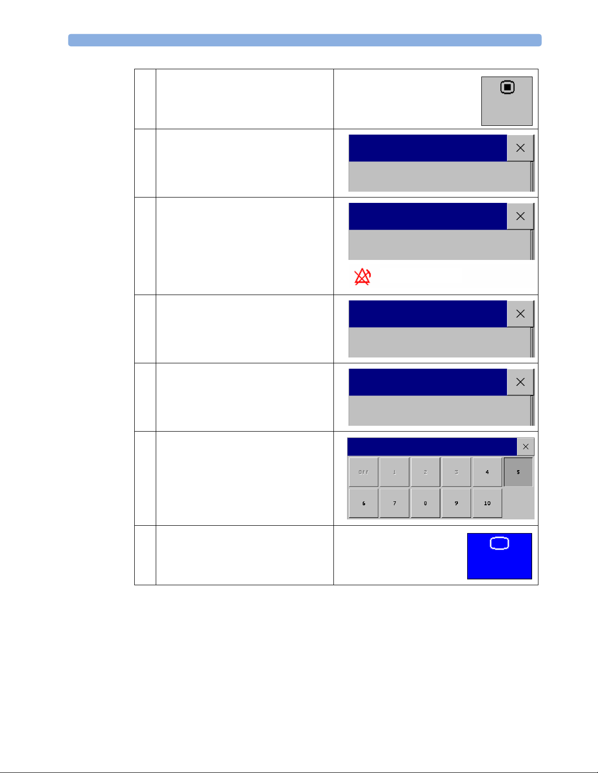
6 Select the Main Setup SmartKey to
open the Main Setup menu.
Main
Setup
7 In the Main Setup menu, select Alarms
to open the Alarms menu.
8 In the Alarms menu, select Alarms Off
to switch all alarms off.
In the alarm status area, the message Alarms
Off appears together with its symbol.
Switch back to activate the alarms again.
9 In the Alarms menu, select Alarm
Settings to open the Alarm Settings
menu.
10 In the Alarm Settings menu, select Alarm
Volume to open the Alarm Volume menu.
Main Setup
Alarms
Alarms
Alarms Off
Alarms OFF
Alarms
Alarm Settings
Alarm Settings
Alarm Volume
11 In the Alarm Volume menu, change the
alarm volume to a different volume. After
selecting one of the different tone volume
numbers, an audible example of the tone
volume is played.
Greyed-out keys are not selectable and only
changeable in Configuration mode.
11 Select the Main Screen SmartKey to
return to the Main Screen.
Alarm Volume
Main
Screen
50
Page 55
Switching NBP On/Off manually 6 Changing Settings
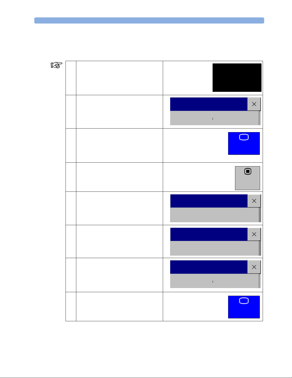
Switching NBP On/Off manually
Monitoring Mode Noninvasive blood pressure is the only measurement which you can manually switch on and off in a
measurement menu.
1 Select the NBP reading on the screen to
open the Setup NBP menu.
(If the NBP reading is not visible on your
current screen, open the Setup NBP menu
as described in step 4 to step 6).
2 In the Setup NBP menu, select NBP to
switch Off the measurement.
3 Select the Main Screen SmartKey to
return to the Main Screen.
The screen display indicates the active
setting, and the NBP reading disappears
from the screen.
4 Select the Main Setup SmartKey to
open the Main Setup menu.
5 In the Main Setup menu, select
Measurements to open the
Measurements menu.
NBP
Setup NBP
NBP Off
Main Setup
Measurements
Man
Main
Screen
Main
Setup
6 In the Measurements menu, select NBP to
open the Setup NBP menu
7 In the Setup NBP menu, select NBP to
switch On the measurement.
The screen display indicates the active
setting and the NBP reading appears again
on the screen.
8 Select the Main Screen SmartKey to
return to the Main Screen.
The NBP reading appears again on the
screen.
Measurements
NBP
Setup NBP
NBP On
Main
Screen
51
Page 56
6 Changing Settings Adjusting Tone Volume
Adjusting Tone Volume
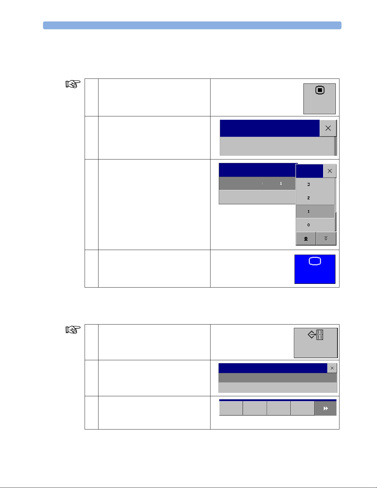
Monitoring Mode In addition to the method of changing the tone volume for measurements, you can also change the
tone volume via the Main Setup menu.
1 Select the Main Setup SmartKey to
open the Main Setup menu.
Main
Setup
2 In the Main Setup menu, select User
Interface to open the User Interface
menu.
3 In the User Interface menu, select QRS
Volume and change the QRS tone
volume.
4 Select the Main Screen SmartKey to
return to the Main Screen.
Main Setup
User Interface
User Interface
QRS Volume
Main
Screen
Stored Data Recording
Monitoring Mode
1 Select the Stored Data Rec
SmartKey to open the Stored Data
Recording menu.
2 In the Stored Data Recording menu, select
an entry for a patient.
3 Select one of the choices on the pop-up
keys to print a specified portion of the entry
(for example, the last 15 minutes of trace
data).
52
Stored
Data Rec
Stored Data Recording
Doe, Jane 14 Nov 16:01 ( 0:36)
Smith, Judy 14 Nov 15:53 (0:57)
All
Last
15 Min
Last
30 Min
Last
60 Min
Page 57
Setting Non-Stress Test Timer 6 Changing Settings
4 For further information about stored data
recording, especially if you are connected to
an OB TraceVue system, refer to
“Recovering Data” in the IfU.
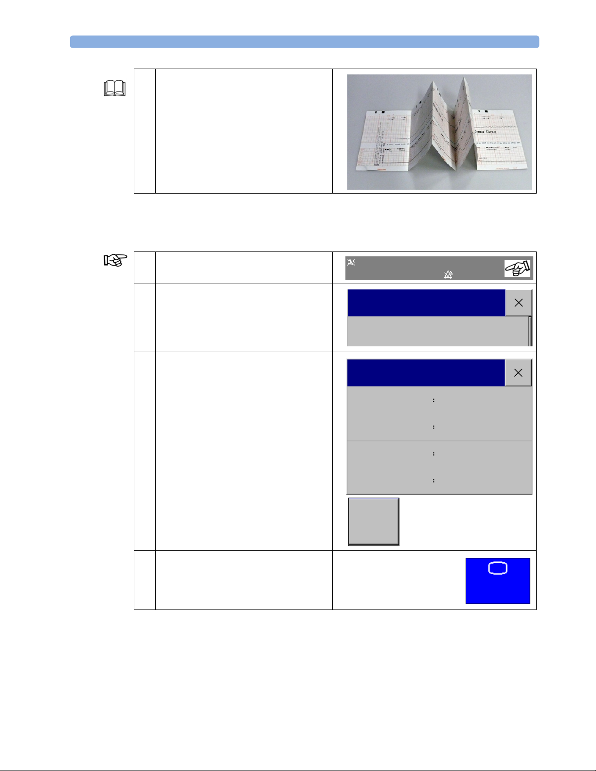
Setting Non-Stress Test Timer
Monitoring Mode
1 Select the INOP and alarm status area to
open the Setup menu.
2 In the Setup menu, select NST Timer to
open the Setup NST Timer menu.
3 In the Setup NST Timer menu,
• select Run Time to define the NST
run time.
• select Notification to define the
timer expiry notification.
• select Timer to set the timer to On, so
that the timer is visible on the top lefthand corner of the screen.
• select Timer Volume to define the
volume of the timer expiry notification.
• Select the Start pop-up key to start
the timer and begin the non-stress test.
Doe, Jane 14 Nov 13:55
Setup
NST Timer
Setup NST Timer
Run Time
Notification
Timer
Timer Volume
Start
INOP Only
20 min
Sound
Off
4
4 Select the Main Screen SmartKey to
return to the Main Screen.
Main
Screen
53
Page 58
6 Changing Settings Setting Non-Stress Test Timer
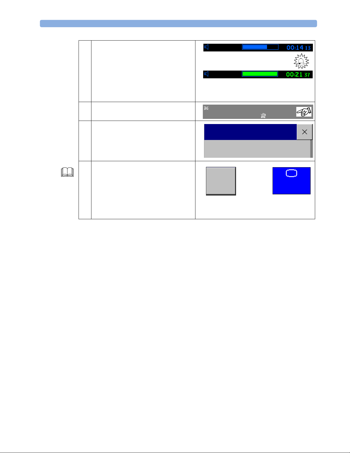
5 The displayed timer shows the elapsed time
from the start.
When the runtime ends the notification
sounds.
After that, the timer changes its color and
counts up from then on.
6 Select the INOP and Alarm Status area to
open the Setup menu.
7 In the Setup menu, select NST Timer to
open the Setup NST Timer menu.
8 In the Setup NST Timer menu, select the
Stop Pop-up key to stop the timer.
Select the Main Screen SmartKey to
return to the Main Screen.
For further information about the
configuration options of the NST, refer to
“Non-stress test timer” in the IfU.
NST
NST
Doe, Jane 14 Nov 13:55
20min
20min
Setup
NST Timer
Stop
INOP Only
Main
Screen
54
Page 59

7Glossary
A
Admitting and Discharging Patients (ADT)
Assigns the current measurements and reading with the patient’s demographics. A discharge deletes the demographics and resets the monitor to its defaults.
Audio in FHR
Audible tone which represents the FHR.
Avalon CTS
Cordless fetal transducer system.
C
Competency
The ability to perform monitoring functions.
Configuration Mode
In Configuration mode, you can define the default settings you work with when you switch on the monitor (it
is password protected). Only personnel trained in configuration tasks are allowed make changes in this mode.
D
DECG
Direct electrocardiogram. The spiral electrode can be applied only after the membranes have been ruptured, and
when the cervix is dilatated two-to-three centimeter or more.
Demo Mode
Generates values and readings for all measurements of the fetal monitor for demonstration and training purposes
only. Never use Demo mode when a patient is attached to the montior.
E
ECG
Electrocardiogram.
Event Marker
Printing a marker to indicate significant events on the trace paper by selecting the Set Marker SmartKey or pressing the button of the remote event marker.
F
Fetal Scalp Electrode
ECG electrode with a spiral on its end to fix the electrode to the fetus’s head.
Fetal Trace Paper
The paper on which the numerics, values, readings, traces, waves, time stamps and patient information is printed.
FHR
Fetal Heart Rate.
55
Page 60

I
INOP
Technical alarm condition. INOP stands for "inoperative".
IUP
Intrauterine Pressure.
IUP Catheter
Catheter to monitor contraction frequency, duration, intensity, and resting tone. It can be introduced transcervically into the uterus after the cervix is dilated two-to-three centimeters, and the fetal membranes have been
ruptured.
L
LAN connection
Connection to a local area network.
M
MECG
Maternal electrocardiogram.
Monitoring Mode
Normal mode for monitoring patients. Items, that are visible but "greyed out" are just for your information, but
can be changed in Configuration mode.
N
NBP
Noninvasive blood pressure.
Non-Stress Test (NST)
Interpretation of FHR and FMP during a defined time with fetal movement, uterine contraction, or in response
to external stimuli.
Notes
Set of pre-configured notes in the monitor. It is possible to edit the notes in Configuration mode.
NST
Non-Stress Test.
Q
Quick Admit
A quickly-admitted patient can be deleted, whereas a normally-admitted patient resides in the system until the
episode is closed and the patient archived or without a storage, until the patient is discharged from OB TraceVue.
R
RS232 connection
Serial interface connection
S
SpO2
56
Page 61

Saturation of peripheral oxygen in the blood.
Standby
When the monitor is in Standby mode after selecting the Standby SmartKey, all waves and numerics disappear,
but all settings and patient data are retained, and a special standby screen is displayed.
T
Toco Baseline
Range of uterine pressure between the labor contractions.
Toco Transducer
Pressure-sensing external transducer to record the duration and frequency of uterine contractions.
Touchscreen
A display screen which can be operated by selecting screen elements with your finger.
Trace Separation
Separation of the baselines on the paper trace by an offset of 20 bpm for a better interpretation of traces with
similar baselines.
Transducer
The link between the patient and the monitor. The transducer transforms the physiological signal into a technical signal, which can be presented, for example on a screen or played by a loudspeaker.
Transferring Patients
Moving patient’s data from one location to another in OB TraceVue.
U
Ultrasound
Sound waves with frequencies higher than 20 Kilohertz.The sound is above the range of human hearing. In the
fetal monitor, ultrasound is used to detect the heart activity of the fetus, and to make it audible.
US Sensor
Ultrasound sensor.
57
Page 62

58
Page 63

8Index
A
admitting patients 39
alarm settings 49
artificial FHR 20
Avalon CTS 28
B
belt
butterfly clip
blood pressure, noninvasive 32
butterfly belt clip 9
9
C
changing settings 49
clip for belt 9
connected to OB TraceVue via LAN 40
connected to OB TraceVue via RS232 43
cordless monitoring 28
D
data, recovering 52
direct ECG 24
discharging patients 39
E
ECG, maternal 35
entering notes 37
event marker 37
F
fetal heart rate 19
DECG 24
fetal movement profile 23
FHR 24
FHR monitoring, DECG 24
FHR, ultrasound 19
finder LED 9
FMP
fetal movement profile
FMP, monitoring 23
FMP, ultrasound 23
23
I
introduction 1
K
keys 13
permanent 13
permanent keys 13
pop-up keys 14
SmartKeys 13
L
LAN connection, status indicator 48
LAN-connection 40
loading paper
FM20/FM30
FM40/FM50 16
15
M
marking event 37
maternal measurements 32
measurement, switching on/off 51
measurements, fetal 23
measurements, maternal 32
MECG 35
monitor standby 22
monitoring
FHR, DECG
FMP 23
MECG 35
NBP 32
pulse rate 33, 35
SpO2 33, 35
twins and triplets 30
uterine activity 21, 26
monitoring cordless 28
24
N
navigating 12
SmartKeys 13
NBP
monitoring
noninvasive blood pressure 32
non-stress test timer 53
notes, entering 37
NST 53
32
O
objectives 5
operating 12
SmartKeys, using 13
overview
Avalon CTS
Avalon FM20/FM30 7
Avalon FM40/FM50 8
fetal monitors 7
transducers 9
overview Avalon FM40/FM50 7
overview transducers 9
10
P
paper trace 21
parameters, general 37
permanent keys 13
Q
Quick Admit to OB TraceVue 40, 44
R
recorder 21
recording data 21
recovering data 52
references 2
RS232-connection 43
S
settings, changing 49
SmartKeys 13
standby, monitor 22
status indicator, LAN connection 48
switching off 22
switching on 19
switching on/off, measurement 51
symbols 1
T
tone volume, adjusting 52
touchscreen 12
transducer
finder LED
transferring patients 39
twins and triplets, monitoring 30
9
U
ultrasound
59
Page 64

FHR 19
usage of training guide 1
uterine activity
externally
21
internally 26
uterine activity monitoring 21, 26
60
 Loading...