

Page 1

10 September 2014
(Preliminary Release Version)
VL4000 Spot Luminaire
Service Manual
Page 2

All other brand or product names which may be mentioned in this manual are trademarks or registered trademarks of their respective companies or
organizations.
Philips Vari-Lite
A Philips Group Company
10911 Petal Street
Dallas, Texas 75238 USA
This manual is for informational use only and is subject to change without notice. Philips Vari-Lite assumes no responsibility or liability for any claims
resulting from errors or inaccuracies that may appear in this manual.
Version as of: 10 September 2014 (Preliminary Release Version)
Part number: 02.9704.0010 0
©2014, Vari-Lite, a Philips group company. All Rights Reserved.
VL4000 Spot Luminaire Service Manual
Page 3

How To Obtain Warranty Service
A copy of the Vari-Lite Limited Warranty was included in the shipping package for this VARI❋LITE
product.
To obtain warranty service, please contact customer service at 1-877-VARI-LITE (1-877-827-4548),
+1-214-647-7880, or [email protected] and request a Return Material Authorization
(RMA) for warranty service. You will need to provide the model and serial number of the item being
returned, a description of the problem or failure and the name of the registered user or organization. If
available, you should have your sales invoice to establish the date of sale as the beginning of the
warranty period.
Once you obtain the RMA, pack the unit in a secure shipping container or in its original packing box.
Fill out the RMA form included at the end of this manual and place in shipping container along with a
copy of your invoice (if available). Write the RMA number legibly on or near the shipping address
label and return the unit, freight prepaid to:
Philips Vari-Lite
10911 Petal Street
Dallas, Texas 75238 USA
Attention: Warranty Service (RMA# _______)
FOREWORD
As stated in the warranty, it is required that the shipment be insured and FOB our service center*.
Note: *When returning products to Philips Vari-Lite for repairs (warranty or out-of-warranty) from a
country other than the USA, “Philips Lighting Controls Division”, must appear in the address block as
the Importer of Record (IOR) on all shipping documentation, Commercial Invoices, etc. This must be
done in order to clear customs in a timely manner and prevent returns.
02.9704.0010 0 i
Page 4
VARI❋LITE - VL4000 SPOT LUMINAIRE SERVICE MANUAL
Compliance Notice
FCC
This equipment has been tested and found to comply with the limits for a Class A digital device
pursuant to Part 15 of FCC Rules. These limits are designed to provide reasonable protection against
harmful interference when this equipment is operated in a commercial environment. This equipment
generates, uses, and can radiate radio frequency energy and, if not installed and used in accordance
with Vari-Lite system, service, and safety guidelines, may cause harmful interference to radio
communications. Operation of this equipment in a residential area is likely to cause harmful
interference, in which case the user will be required to correct the interference at his/her own expense.
Declaration of Conformity
We, Philips Lighting B.V. 10911 Petal Street, Dallas, Texas 75238 USA, declare under our
responsibility for the products:
Product Range Professional Stag e Luminaire
Product Code VL4000 Spot
The designated products are in conformity with the essential requirements of the following European
Directives and harmonized standards:
Low Voltage Directive (LVD), 2006/95/EC
EN 60589-2-17:1984+A1:1987+A2:1990 used in conjunction with 60598-1:2008/A11:2009
Electromagnetic Compatibility Directive (EMC), 2004/108/EC
EN 55022:2010, EN55024:2010
ii 02.9704.0010 0
Page 5

Safety Notice
It is extremely important to read ALL safety information and instructions provided in this manual and
any accompanying documentation before installing and operating the products described herein. Heed
all cautions and warnings during installation and use of this product.
Safety symbols used throughout this manual are as follows:
GENERAL INFORMATION PERTAINING TO PROTECTION AGAINST ELECTRICAL SHOCK,
FIRE, EXPOSURE TO EXCESSIVE UV RADIAT ION, AND INJURY TO PERSONS CAN BE
FOUND BELOW.
WARNING:
INSTRUCTIONS FOR CONTINUED PROTECTION AGAINST FIRE
1. VARI❋LITE lumi naires have been designed for use with specific lamp types. VL4000 Spot
Luminaires is supplied with an Osram HTI 1500 D7/60 metal halide lamp or other lamps as
approved by Vari-Lite. Installing another type of lamp not approved by Vari-Lite may be
hazardous.
2. Luminaires may be mounted on any type of surface as long as mounting instructions are followed.
See instructions detailed in this manual.
3. Note distance requirement from combustible materials or illuminated objects for VARI❋LITE
luminaires.
FOREWORD
CAUTION advising of potential damage to product.
WARNING advising of potential injury or death to persons.
WARNING:
INSTRUCTIONS FOR CONTINUED PROTECTION AGAINST ELECTRICAL SHOCK
1. VARI❋LITE luminaires are designed for dry locations only. Exposure to rain or moisture may
damage luminaire.
2. Disconnect power before servicing any VARI❋LITE equipment.
3. Servicing to be performed by qualified personnel only.
02.9704.0010 0 iii
Page 6

VARI❋LITE - VL4000 SPOT LUMINAIRE SERVICE MANUAL
WARNING:
INSTRUCTIONS FOR CONTINUED PROTECTION AGAINST EXCESSIVE EXPOSURE
TO UV RADIATION
1. Many VARI❋LITE lum i naires use a lamp that produces UV radiation. DO NOT look directly at
lamp.
2. It is hazardous to operate luminaires without lens or shield. Shields, lenses, or ultraviolet screens
shall be changed if they have become visibly damaged to such an extent that their effectiveness is
impaired. For example, by cracks or deep scratches.
WARNING:
INSTRUCTIONS FOR PROTECTION AGAINST INJURY TO PERSONS
1. Exterior surfaces of the luminaire will be hot during operation. Use appropriate safety equipment
(gloves, eye protection, etc.) when handling and adjusting hot equipment and components.
2. Luminaires will have a hot lamp when operating. Disconnect power and allow lamp to cool before
replacing.
3. Arc lamps emit ultraviolet radiation which can cause serious skin burn and eye inflammation.
Additionally, arc lamps operate under high pressure at very high temperatures. Should the lamp
break, there can exist a danger of personal injury and/or fire from broken lamp particles being
discharged.
4. Wear eye protection when relamping.
5. Appropriate safety equipment (gloves, eye protection) should be used when handling damaged
lamps.
6. If lamp is touched with bare hands, clean lamp with denatured alcohol and wipe with lint-free
cloth before installing or powering up the luminaire.
7. The lamp shall be changed if it has become damaged or thermally deformed.
WARNING:
RF INTERFERENCE
1. This is a Class A product. In a domestic environment this product may cause radio interference, in
which case, the user may be required to take adequate measures.
ARC LAMP CHARACTERISTIC CONSIDERATIONS
1. Arc lamps require a period of time to relight after a power interruption or a severe voltage dip. In
some cases, the lamp will automatically relight after it has cooled depending on Lamp Power-Up
State configuration setting.
2. Burning position is universal.
iv 02.9704.0010 0
Page 7

Sicherheitshinweise
Es ist äußerst wichtig, ALLE Sicherheitsinformationen und -hinweise in diesem Handbuch und dem
beiliegenden Informationsmaterial zu lesen, bevor Sie die hierin beschriebenen Produkte installieren
bzw. bedienen. Halten Sie bei der Installation und dem Einsatz dieses Produkts alle Warnhinweise und
Vorsichtsmaßnahmen ein.
Folgende Sicherheitssymbole werden in diesem Handbuch verwendet:
VORSICHT - weist auf möglichen Produktschaden hin.
WARNUNG - weist auf mögliche Körperverletzung und Lebensbedrohung hin.
NACHSTEHEND FINDEN SIE ALLGEMEINE HINWEISE ÜBER
SICHERHEITSVORKEHRUNGEN GEGEN ELEKTROSCHOCK, FEUER, ÜBERHÖHTE UVSTRAHLUNG UND KÖRPERVERLETZUNGEN.
WARNUNG:
HINWEISE ZUM FEUERSCHUTZ
1. VARI❋LITE -Scheinwerfer sind ausschließlich für den Einsatz mit bestimmte n Lampentyps.
Achten Sie auf den Lampentyp (Osram HTI 1500 D7/60 metal halide lamp), bevor Sie die
jeweiligen Lampen ersetzen. Die Installation eines anderen Lampentyps kann gefährlich sein.
2. Scheinwerfer können auf jeder beliebigen Oberfläche montiert werden, solange Sie die
Montageanweisungen befolgen. Detaillierte Hinweise finden Sie in diesem Handbuch.
3. Beachten Sie die Einhaltung des erforderlichen Sicherheitsabstandes der VARI❋LITE Scheinwerfer von brennbarem Material oder beleuchteten Objekten.
FOREWORD
WARNUNG:
HINWEISE ZUM SCHUTZ GEGEN ELEKTROSCHOCK
1. VARI❋LITE -Scheinwerfer eignen sich ausschließlich für trockene Standorte. Regen oder
Feuchtigkeit können die Scheinwerfer beschädigen.
2. Unterbrechen Sie die Stromzufuhr, bevor Sie mit der Arbeit an VARI❋LITE -Geräten beginnen.
3. Die Geräte sollten nur von qualifiziertem Personal gewartet werden.
02.9704.0010 0 v
Page 8

VARI❋LITE - VL4000 SPOT LUMINAIRE SERVICE MANUAL
WARNUNG:
HINWEISE ZUM SCHUTZ GEGEN ÜBERHÖHTE UV-STRAHLUNG
1. Viele VARI❋LITE -Scheinwerfer verwenden die Lampentyp, der UV-Strahlen abgibt. SCHAUEN
SIE NICHT direkt in die Lampe.
2. Es ist gefährlich, Leuchten ohne Linsen oder Blenden zu bedienen. Blenden, Linse n oder
Ultraviolettschirme müssen ausgetauscht werden, sofern deren Schutzwirkung durch sichtbare
Beschädigung (z. B. Sprünge oder Schrammen) eingeschränkt ist.
WARNUNG:
HINWEISE ZUM SCHUTZ GEGEN KÖRPERVERLETZUNGEN
1. Bei Betrieb sind die Außenflächen der Scheinwerfer heiß. Verwenden Sie bei der Bedienung von
aufgeheizter Apparatur die jeweils geeignete Sicherheitsausrüstung (Handschuhe, Augenschutz
etc.).
2. Bei Betrieb der Scheinwerfer ist die Lampe heiß. Unterbrechen Sie die Stromzufuhr und lassen Sie
die Lampe abkühlen, wenn Sie diese austauschen.
3. Bogenlampen senden ultraviolette Strahlen aus, die Hautverbrennungen und Augenentzündungen
verursachen können. Der Betrieb von Bogenlampen erfolgt unter Hochdruck und bei hohen
Temperaturen. Sollte die Lampe zerbrechen, besteht die Gefahr von Körperverletzung bzw. von
Feuer, das von Lampenteilen ausgelöst werden kann.
4. Tragen Sie beim Austausch der Lampen einen Augenschutz.
5. Die geeignete Sicherheitsausrüstung (Handschuhe, Augenschutz) sollte beim Umgang mit
beschädigten Lampen verwendet werden.
6. Wenn die Lampe mit bloßen Händen berührt wird , reinigen Sie sie mit denaturi ertem Alkohol und
einem flusenfreien Tuch, bevor Sie die Scheinwerfer installieren oder in Betrieb nehmen.
7. Wenn die Lampe beschädigt oder durch Hitzeeinwirkung deformiert ist, muß diese ausgetauscht
werden.
WARNUNG:
HF-INTERFERENZ
1. Es handelt sich um ein Produkt der Klasse A. In einer Wohnumgebung kann das Produkt Hochfrequenzstörungen verursachen. In diesem Fall müssen eventuell geeignete Maßnahmen getroffen
werden.
BESONDERHEITEN VON BOGENLAMPEN
1. Bogenlampen benötigen eine gewisse Zeitdauer, um nach einem Stromausfall oder einem
Spannungsgefälle wieder aufzuleuchten. In einigen Fällen wird die Lampe nach Abkühlung
automatisch wieder aufleuchten, je nach der Systemkonfigurationseinstellung des Lampeneinschaltungsstatus.
2. Die Brennposition ist Universal.
vi 02.9704.0010 0
Page 9

Notes de sécurité
Avant de procéder à l’installation des produits décrits dans ce guide et de les mettre en marche, il est
extrêmement important de lire TOUS les renseignements et TOUTES les directives de sécurité
contenues dans ce guide ainsi que toute documentation jointe. Tenir compte de tous les avertissements
et suivre toutes les précautions pendant l’installation et l’utilisation de cet appareil.
Les symboles de sécurité utilisés dans ce guide sont les suivants :
ATTENTION Ce symbole annonce que l’appareil risque d’être endommagé.
AVERTISSEMENT Ce symbole annonce qu’il y a risque d’accident grave ou même fatal.
CETTE SECTION CONTIENT DES INFORMATIONS GÉNÉRALES POUR SE PROTÉGER
CONTRE LES DÉCHARGES ÉLECTRIQUES , LES INCENDIES, L’EXPOSITION EXCESSIVE
AUX RAYONS UV ET TOUT AUTRE ACCIDENT POUVANT ENTRAÎNER DES BLESSURES.
FOREWORD
AVERTISSEMENT:
DIRECTIVES POUR SE PROTÉGER CONTRE LES INCENDIES
1. Les luminaires VARI❋LITE ont été conçus pour être utilisés uniquement avec certaines type de
lampes. Vérifier le type de lampe (Osram HTI 1500 D7/60 metal halide lamp) avant de remplacer
les lampes. L’installation d’un autre type de lampe peut poser un danger.
2. Les luminaires peuvent être fixés sur tout type de surface tant que les directives de montage sont
respectées. Voir les explications détaillées dans ce guide.
3. Vérifier la distance à respecter entre les matériaux combustibles ou les objets illuminés et les
luminaires VARI❋LITE .
AVERTISSEMENT:
DIRECTIVES POUR SE PROTÉGER CONTRE LES DÉCHARGES ÉLECTRIQUES
1. Les luminaires VARI❋LITE sont conçus pour une utilisation au sec uniquement. Une exposition
à la pluie et à l’humidité risque d’endommager le luminaire.
2. Débrancher l’appareil avant de procéder à la révision de tout matériel VARI❋LITE .
3. Les révisions doivent être effectuées uniquement par des personnes qualifiées.
02.9704.0010 0 vii
Page 10

VARI❋LITE - VL4000 SPOT LUMINAIRE SERVICE MANUAL
AVERTISSEMENT:
DIRECTIVES POUR SE PROTÉGER CONTRE UNE EXPOSITION EXCESSIVE AUX
RAYONS UV
1. Plusieurs luminaires VARI❋LITE utilisent une lampe qui produit des rayons UV. NE PAS fixer
son regard sur la lampe.
2. L’utilisation des luminaires sans lentille ou blindage pose des risques. Tous blindages, lentilles ou
écrans ultraviolet visiblement endommagés au point que leur efficacité en est affectée doivent être
remplacés, par exemple s’il y a des fissures ou de profondes rayures.
AVERTISSEMENT:
DIRECTIVES POUR SE PROTÉGER CONTRE LES ACCIDENTS POUVANT ENTRAÎNER
DES BLESSURES
1. Les surfaces externes du luminaire deviennent brûlantes quand l’appareil est en marche. Pour
manœuvrer ou ajuster des appareils brûlants et leurs composants, se protéger suffisamment (gants,
protection pour les yeux, etc.).
2. La lampe du luminaire est brûlante lorqu’il est en marche. Débrancher le courant et attendre que la
lampe ait refroidi avant de la remplacer.
3. Les lampes à arc émettent des rayons ultraviolets pouvant causer de graves brûlures sur la peau et
une inflammation des yeux. De plus, les lampes à arc fonctionnent sous haute tension à de très
hautes températures. Si la lampe se casse, les particules de la lampe cassée peuvent causer
blessures et/ou incendie en s’éparpillant.
4. Se protéger les yeux pour remplacer la lampe.
5. Utiliser des appareils de protection appropriés (gants, protection des yeux) pour manier des lampes
endommagées.
6. Si la lampe a été touchée avec des mains nues, la nettoyer avec de l’alcool dénaturé et l’essuyer
avec un chiffon non-pelucheux avant d’installer ou de brancher le luminaire.
7. Si la lampe a été endommagée ou a reçu une déformation thermique, elle doit être remplacée.
AVERTISSEMENT:
INTERFÉRENCE RF
1. Cet appareil est de Classe A. Dans un environnement domestique, cet appareil peut causer des
interférences radio, et si c’est le cas, l’utilisateur peut avoir à prendre des mesures adéquates.
CONSIDÉRATIONS DES CARACTÉRISTIQUES DE LAMPES À ARC
1. Après une interruption de courant ou une baisse importante de voltage, les lampes à arc mettent du
temps avant de se rallumer. Dans certains cas, la lampe se rallumera automatiquemet après s’être
refroidie. Cela dépend de la manière dont le système est réglé pour le statut de mise en marche de
la lampe.
2. La position Brûler est Universelle.
viii 02.9704.0010 0
Page 11

Aviso sobre Seguridad
Es muy importante leer TODA la in formación e instrucciones sobre seguridad que se indica en es te
manual así como en los documentos adjuntos antes de instalar y operar los productos descritos. Se
debe prestar atención a todos los avisos y advertencias durante la instalación y uso de este producto.
Los símbolos de seguridad usados en este manual son los siguientes:
CUIDADO, indica posibles daños al producto.
ADVERTENCIA, indica posibles lesiones o muerte a las personas.
LA INFORMACIÓN GENERAL RELACIONADA A LA PROTECCIÓN CONTRAGOLPES DE
CORRIENTE ELÉCTRICA, INCENDIO, EXPOSICIÓN EXCESIVA A RADIACIÓN ULTRA
VIOLETA Y LESIONES A LAS PERSONAS SE PUEDE ENCONTRAR SEGUIDAMENTE:
ADVERTENCIA:
INSTRUCCIONES PARA PROTECCIÓN CONTINUA CONTRA INCENDIO
1. Las luminarias VARI❋LITE han sido diseñadas para ser usadas solamente con algunas lámparas.
T ome nota del tipo d e lámpara (Osram HTI 1500 D7/60 metal halide lamp) antes de reemplazarla.
Instalación de otro tipo de lámpara puede ser peligroso.
2. Las luminarias se pueden instalar en cualquier tipo de superficie siempre que se sigan las
instrucciones de instalación. Vea las instrucciones detalladas en este manual.
3. Tome nota de los requerimientos de distancia de materiales combustibles u objetos iluminados
para las luminarias VARI❋LITE .
FOREWORD
ADVERTENCIA:
INSTRUCCIONES PARA PROTECCIÓN CONTINUA CONTRA CHOQUE ELÉCTRICO
1. Las luminarias VARI❋LITE están diseñadas solamente para lugares secos. La exposición a la
lluvia o humedad pueden dañar la luminaria.
2. Desconecte la energía antes de dar servicio a cualquier equipo de VA RI❋LITE .
3. El servicio debe ser realizado solamente por personal calificado .
02.9704.0010 0 ix
Page 12

VARI❋LITE - VL4000 SPOT LUMINAIRE SERVICE MANUAL
ADVERTENCIA:
INSTRUCCIONES PARA PROTECCIÓN CONTINUA CONTRA LA EXPOSICIÓN
EXCESIVA DE RADIACIÓN ULTRA VIOLETA
1. Muchas luminarias VARI❋LITE usan un tipo de lámpara que produce radiación UV. NO mire
directamente a la lámpara.
2. Es peligroso operar luminarias sin lentes o protectores. Debe cambiar los protectores, lentes o
pantallas ultravioletas si se aprecia que han sido dañadas, y que su efectividad pudiera estar
deteriorada. Por ejemplo, si tuvieran rajaduras o raspaduras profundas.
ADVERTENCIA:
INSTRUCCIONES PARA PROTECCIÓN CONTRA LESIONES DE PERSONAS
1. Las superficies exteriores de las luminarias están calientes durante su operación. Use un equipo de
seguridad apropiado (guantes, protección para los ojos, etc.) cuando haga ajustes en el equipo y
componentes que están calientes.
2. Cuando las luminarias están en operación la lámpara estará muy caliente. Desconecte la energía y
deje que la lámpara se enfríe antes de reemplazarla.
3. Las lámparas de arco emiten radiaciones ultravioletas que pueden ocasionar serias quemaduras a la
piel e inflamación a los ojos. Además, las lámparas de arco operan a alta presión y muy alta
temperatura. Si la lámpara se rompe, puede existir el peligro de lesiones al personal o un incendio
ocasionado por las partículas de la lámpara rota que se caen.
4. Use protección para los ojos cuando vuelve a colocar una lámpara nueva.
5. Use un equipo de seguridad apropiado (guantes, protección para los ojos, etc.) cuando trabaje con
lámparas dañadas.
6. Si toca la lámpara con las manos, limpie la lámpara con alcohol desnaturalizado y con tela sin
pelusas antes de instalar o volver a conectar la luminaria.
7. Cambie la lámpara si está dañada o deformada termicamente.
ADVERTENCIA:
INTERFERENCIA RF
1. Este es un producto de Clase A. En el ambiente de la casa este producto puede ocasionar
radiointerferencia, en cuyo caso, el usuario debe tomar las medidas adecuadas.
CONSIDERACIONES SOBRE LAS CARACTERÍSTICAS DE LA LÁMPARA DE ARCO
1. Las lámparas de arco requieren un período de tiempo para volver a iluminarse después de una
interrupción de energía o de una severa caída de voltaje. En algunos casos, la lámpara se volverá a
iluminar en forma automática después que se ha enfriado dependiendo de la configuración del
sistema de energía de la lámpara.
2. La posición de encendido es universal.
x 02.9704.0010 0
Page 13
FOREWORD
02.9704.0010 0 xi
Page 14
VARI❋LITE - VL4000 SPOT LUMINAIRE SERVICE MANUAL
xii 02.9704.0010 0
Page 15

Table of Contents
Introduction
About This Manual ...................................................... ............................................................. 1
Additional Documentation........................................................................................................ 1
Customer Service...................................................................................................................... 2
Technical Bulletins and Notices................................................................................................ 2
Chapter 1. Description
Features
Product Features........................................................................................................................ 4
Technical Specifications ........................................................................................................... 5
Components
External Luminaire Components.............................................................................................. 6
Head and Yoke Components..................................................................................................... 7
Enclosure Components ............................................................................................................. 8
TABLE OF CONTENTS
Chapter 2. Rountine Maintenance
Troubleshooting
Error Messages........................................................................................................................ 10
Troubleshooting Guide............................................................................................................ 11
Routine Maintenance Procedures
Lamp Removal and Installation.............................................................................................. 13
Fixed Color Wheel Filter Removal and Installation............................................. .................. 16
Rotating Gobo Removal and Installation................................................................................ 18
Animation Wheels Removal and Installation .............................................. .... ..... .................. 21
Cleaning Optical Lenses and Filters ....................................................................................... 23
Chapter 3. Illustrated Parts Breakdown
Drawing Trees
VL4000 Spot Luminaire (Part 1)............................................................................................ 26
VL4000 Spot Luminaire (Part 2)............................................................................................ 27
VL4000 Spot Luminaire (Part 3)............................................................................................ 28
VL4000 Spot Luminaire (Part 4)............................................................................................ 29
VL4000 Spot Luminaire (Part 5)............................................................................................ 30
VL4000 Spot Luminaire (Part 6)............................................................................................ 31
Principle of Operation
VL4000 Spot Functional Block Diagram ............................................................................... 32
Top Assembly
Included Items Kit, VL4000 Spot........................................................................................... 33
02.9704.0010 0 xiii
Page 16

VARI❋LITE - VL4000 SPOT LUMINAIRE SERVICE MANUAL
VL4000 Spot Luminaire ......................................................................................................... 35
VL4000 Generic Luminaire Assembly................................................................................... 37
VL4000 Head Cover Assembly.............................................................................................. 39
VL4000 Yoke Arm Cover Assembly........................................................... ........................... 40
Stabilizer Assembly ................................................................................................................ 41
Head Assembly
Head Frame Assembly............................................................................................................ 43
VL4000 Zoom Spot Assembly ............................................................................................... 45
Prism Motor Assembly ........................................................................................................... 49
Prism Assembly ...................................................................................................................... 51
Frost Motor Assembly ............................................................................................................ 53
Frost Flag Assembly ............................................................................................................... 55
Lens Group 3 Motor Assembly............................................................................................... 56
Slotted Optical Switch ............................................................................................................ 58
Back End Assembly................................................................................................................ 59
Reflector Assembly................................................................................................................. 61
Lamp Cover Assembly............................................................................................................ 62
Shutter/Gobo/Animation Module Assembly ............................................................ ..... ......... 63
Gobo Wheel 1 Assembly ........................................................................................................ 69
Gobo Wheel 2 Assembly ........................................................................................................ 71
Gobo 1 Sensor Index Assembly.............................................................................................. 73
Gobo 2 Sensor Index Assembly.............................................................................................. 74
Edge Motor Assembly ............................................................................................................ 75
Gobo Bulkhead Left Bracket Assembly ................................................................................. 76
Gobo Bulkhead Right Bracket Assembly............................................................................... 77
Animation Wheel 1 Assembly................................................................................................ 78
Animation Wheel 1 Motor Assembly..................................................................................... 80
Animation Wheel 2 Assembly................................................................................................ 81
Animation Wheel 2 Motor Assembly..................................................................................... 83
Shutter Bulkhead with Rotation Assembly............................................................................. 84
Shutter Module Assembly....................................................................................................... 86
Shutter Rotate Motor Assembly.............................................................................................. 90
Shutter Rotate Adjustable Roller Arm Assembly................................................................... 91
Color Module Assembly......................................................................................................... 93
210 Groove Belt Assembly..................................................................................................... 98
240 Groove Belt Assembly..................................................................................................... 99
Fixed Color Wheel Assembly............................................................................................... 100
Fixed Color Wheel 1 Assembly............................................................................................ 102
Fixed Color Wheel 2 Assembly............................................................................................ 104
Fixed Color Motor Assembly ............................................................................................... 106
Cross-Flow Blower Assembly.............................................................................................. 107
Left Strobe Assembly............................................................................................................ 108
Right Strobe Assembly ......................................................................................................... 110
Control Belt Idler Assembly................................................................................................. 112
Color Flags Sensor Board Assembly.................................................................................... 113
Yoke Assembly
Yoke Assembly ..................................................................................................................... 115
Tilt Motor Assembly............................................................................................................
. 117
xiv 02.9704.0010 0
Page 17

TABLE OF CONTENTS
Tilt Motor with Pulley Assembly.......................................................................................... 119
Enclosure Assembly
Upper Enclosure Assembly................................................................................................... 121
Upper Enclosure Assembly - Part 1...................................................................................... 122
Upper Enclosure Assembly - Part 2...................................................................................... 124
Upper Enclosure Assembly - Part 3...................................................................................... 126
Upper Enclosure Assembly - Part 4...................................................................................... 128
Side Mount Fan Assembly.................................................................................................... 130
Front Panel Assembly....................................................... .... ..... .... ....................................... 131
Side Mount Filter Holder Assembly..................................................................................... 133
Pan Bearing / Pulley Assembly............................................................................................. 134
Pan / Fan Driver Board Assembly ........................................................................................ 136
Pan Module Assembly.......................................................................................................... 137
Upper Enclosure Cover Assembly........................................................................................ 139
Note: Cables are only available as complete assemblies. The information contained in this
section is for reference only.
Cable Assemblies
LVS Chassis Ground Cable Assembly.................................................................................. 141
VL4000 Pan / Tilt Cable Assembly...................................................................................... 142
VL4000 Tilt Cable Assembly............................................................................................... 143
VL4000 Color Power Distribution Cable Assembly ............................................................ 144
VL4000 Main from MCB Data Cable Assembly ................................................................. 145
VL4000 Main to Bulkheads Data Cable Assembly.............................................................. 146
VL4000 Lamp Base & Tip Fan Extension Cable Assembly................................................ 147
VL4000 Main Power Distribution Cable Assembly............................................................. 148
VL4000 Lamp Socket Cable Assembly................................................................................ 149
VL4000 Gobo Bulkhead 1 Cable Assembly......................................................................... 150
VL4000 Gobo Bulkhead 2 Cable Assembly......................................................................... 151
VL4000 Gobo Bulkhead 3 Cable Assembly......................................................................... 152
VL4000 Data Network Extension Cable Assembly ............................................................. 153
VL4000 Shutter 1 Cable Assembly ...................................................................................... 154
VL4000 Shutter 2 Cable Assembly ...................................................................................... 155
VL4000 Shutter 3 Cable Assembly ...................................................................................... 156
VL4000 Power Distribution Output-Shutter Cable Assembly ............................................. 157
VL4000 Data Network Cable Assembly .............................................................................. 158
VL4000 Color Bulkhead 1 Cable Assembly......................................................................... 159
VL4000 Color Bulkhead 2 Cable Assembly......................................................................... 160
VL4000 Color Bulkhead 3 Cable Assembly......................................................................... 161
VL4000 Color Bulkhead 4 Cable Assembly......................................................................... 162
VL4000 Color A to Color B Cable Assembly...................................................................... 163
VL4000 Ballast to Ignitor Cable Assembly.......................................................................... 164
VL4000 Pan / Power Distribution Input Cable Assembly.................................................... 165
VL4000 Enclosure PFC Input Cable Assembly ................................................................... 166
VL4000 Enclosure PFC Output Cable Assembly................................................................. 167
VL4000 DMX Cable Assembly............................................................................................ 168
VL4000 Ballast Control Cable Assembly............................................................................. 169
02.9704.0010 0 xv
Page 18

VARI❋LITE - VL4000 SPOT LUMINAIRE SERVICE MANUAL
VL4000 USB Interface Cable Assembly.............................................................................. 170
VL4000 Thermal Control Cable Assembly.......................................................................... 171
VL4000 Chassis to Yoke Cable Assembly........................................................................... 172
VL4000 AC Input Connector Assembly............................................................................... 173
VL4000 Optics-E to Optics-F Data Cable Assembly........................................................... 174
VL4000 Optics Bulkhead 3 Cable Assembly....................................................................... 175
VL4000 Optics Bulkhead 4 Cable Assembly....................................................................... 176
VL4000 Optics Bulkhead 1 Cable Assembly....................................................................... 177
VL4000 Optics Bulkhead 2 Cable Assembly....................................................................... 178
Appendix A. Technical Notices & Bulletins
VL4000 Spot Luminaire ....................................................................................................... 179
Technical Notices............................................................................................................ 179
Technical Bulletins.......................................................................................................... 179
xvi 02.9704.0010 0
Page 19
Introduction
About This Manual
This manual provides descriptions, repair procedures, and illustrated parts breakdowns for the
VL4000 Spot Luminaire. The manual is intended for use by Vari-Lite personnel and Authorized
VARI❋LITE Service Centers and technicians only.
WARNING: It is important to read ALL accompanying safety and installation instructions to avoid
damage to the product and potential injury to yourself or others.
This manual covers the following models:
VL4000 Spot Luminaire 20.9704.0001 1200W Short Arc
INTRODUCTION : ABOUT THIS MANUAL
Model Part Number Source
Note: Performing maintenance procedures may void the product warranty. Refer to the Vari-Lite
Limited Warranty card included in the product shipping package for more information.
Additional Documentation
For complete installation and operation instructions, refer to the VL4000 Spot Luminaire User’s
Manual. This manual is only available in electronic (PDF) format:
• VL4000 Spot Luminaire User’s Manual (02.9704.0002)
Note: The user’s manual is available on the Philips Vari-Lite web site at www.vari-lite.com in the
Product Downloads Section.
For more information regarding DMX512 systems, refer to the DMX512/1990 & AMX 192 Standards
publication available from United States Institute for Theatre Technology, Inc. (USITT).
USITT Inc.
315 South Crouse Avenue Suite 200
Syracuse, NY 13210
Tel: 800-938-7488 or +1-315-463-6463
Fax: 866-398-7488 or +1-315-463-6525
www.usitt.org
02.9704.0010 0 1
Page 20

VARI❋LITE - VL4000 SPOT LUMINAIRE SERVICE MANUAL
Customer Service
Our Goal
At Vari-Lite, we are committed to providing you the highest quality in customer service. Our
comprehensive resources are available to help your business succeed and ensure you get the full
benefit of being a Vari-Lite customer. Whether your needs are telephone troubleshooting assistance,
product training or technical service, our full-time staff of experienced professionals are on-hand to
provide support.
How to Reach Us
For assistance in your area, call the dealer from which your product(s) was purchased.
or
Contact an Authorized Service Center.
or
Contact the Vari-Lite Customer Service Department, 9am - 6pm CST Monday through Friday, at the
following:
phone: 1-877-VARI-LITE (1-877-827-4548)
e-mail: [email protected]
Additional Resources
For additional resources and documentation, please visit our website at www.vari-lite.com and follow
the Support link.
Technical Bulletins and Notices
Technical bulletins concerning the latest changes to VARI❋LITE equipment are issued from the
Dallas, T exas USA office. They are documentation supplements that contain procedures for equipmen t
upgrades, retrofits, and repairs not found in the existing manuals. Operator technical bulletins are also
issued to document changes in control software. Technical bulletins are integrated into the appropriate
equipment manuals as those manuals are revised. Bulletins are categorized by assembly or
subassembly, and identified by a number such as S3K-001 (Series 3000 Lumin aires Technical Bulletin
number 1).
Technical notices are also issued from the Dallas, Texas USA office. They are non-procedural
documents that contain information regarding product support issues, current equipment problems,
software bugs, and documentation corrections. All technical notices begin with the prefix TN and are
numbered sequentially, such as TN-138 (Tech Notice number 138).
2 02.9704.0010 0
Page 21

CHAPTER 1.
Description
This chapter contains descriptions of luminaire features and components.
• Features
• Components
02.9704.0010 0 3
Page 22

VARI❋LITE - VL4000 SPOT LUMINAIRE SERVICE MANUAL
Features
Product Features
All VL4000 Spot Luminaires have the following standard features:
• Color System: A three filter CYM cross fading system capable of extremely smooth movements at
both slow and fast speeds, and a variable CTO color temperature correction system.
• Fixed Color Wheels: T wo opposing fixed color wheels each with five interchangeable color filters
are capable of producing multi-color effects and variable wheel rotations.
• Zoom Optics: A 12-element 5:1 zoom optics system, covering a range from 9° to 47°.
• Beam Size Control: A mechanical iris provides continuous beam size control for rapid and smooth
timed beam angle changes.
• Shutter Control: A four-blade shutter mechanism that allows the blades to be operated
independently or in unison on two planes for a clear and crisp image. The entire mechanism can
rotate 50º in either direction.
• Rotating Gobo Wheels: Two gobo wheels combine to each offer seven rotatable, indexable gobo
positions and one open position.
• Animation Wheels: Two animation wheels each offer unique rotatable, indexable patterns with
variable motion control from horizontal to vertical . Unique Dichro*Fusion pattern is chromatically
tuned to provide endless color effects.
• Rotating Prism: Independent rotating and indexing 3-facet prism with variable deviation control.
• Edge and Pattern Focus: Variable beam focus to soften edges of gobos or spot. Remarkable depth
of field capability allows morphing effects between gobo and animation wheels.
• Variable Frost: Independent variable frost glass with adjustable softness control.
• Intensity Control: Full field dimming designed for smooth timed fades as well as quick dimming
effects.
• Strobe: High-performance dual blade strobe system capable of ultra-fast operation.
• Pan and Tilt: Smooth, time-controlled continuous motion by way of three-phase stepper motor
systems.
• Range: Pan - 540°, Tilt - 270°.
• Accuracy: 0.1° resolution.
• Weights: Unit weighs (luminaire only, without accessories) 83 lbs (37.7 kg).
• Spacing: Unit hangs on 25 inch (635 mm) centers.
• Operational Temperature:
• Standard Mode: -20° to +104° F (-29° to +40° C)
• Studio Mode: -20° to +122° F (-29° to +50° C)
• Control:
• DMX: Completely compatible with a wide variety of DMX512 consoles.
• DMX Channels: 57 (Enhanced 16-bit mode) / 52 (16-bit mode).
4 02.9704.0010 0
Page 23

FEATURES : TECHNICAL SPECIFICATIONS
1
• RDM Control: Completely compatible with a wide variety of RDM devices.
• Power Requirements: Standard AC power distribution from 200 - 240VAC, 50/60 Hz. The unit
requires up to 11.0A depending on the AC supply voltage.
• Source: 1200W Short Arc Lamp, Philips MSR Gold FastFit.
Technical Specifications
For additional technical specifications and information, please refer to VL4000 Spot Luminaire User’s
Manual (02.9704.0002) and the product specification sheet. These documents can be found in the
product downloads section of the Vari-Lite web site at www.vari-lite.com.
02.9704.0010 0 5
Page 24
VARI❋LITE - VL4000 SPOT LUMINAIRE SERVICE MANUAL
Components
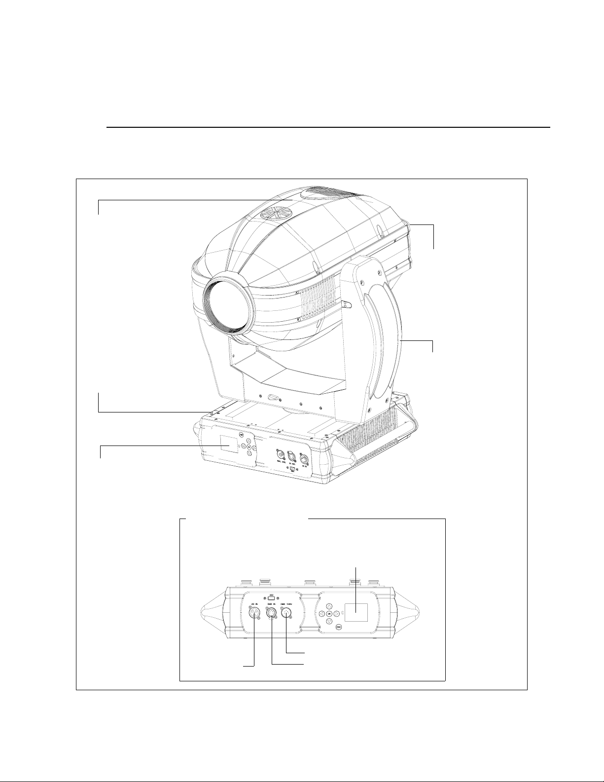
External Luminaire Components
The following illustration shows the external luminaire components and controls.
Head Assembly
Houses color system,
gobos, animation
wheels, strobe, iris and
zoom lens mechanisms
Backcap Assembly
Provides access to lamp
for replacement and
provides controls for
beam adjustment.
Upper Enclosure Assembly
Houses power supply, PFC,
lamp driver, pan motor
assembly, and display board.
Input Panel
Provides DMX In and Thru,
and AC Power connections.
(see detail below)
Input Panel Components
Yoke Assembly
Houses Master Control
Board (MCB), tilt motor,
ignitor, and cooling fans.
Menu Display
Used to input manual
commands, program, test,
set defaults and access
internal status information.
Data Thru
AC Input
6 02.9704.0010 0
Data In
Page 25
COMPONENTS : HEAD AND YOKE COMPONENTS
1
Head and Yoke Components
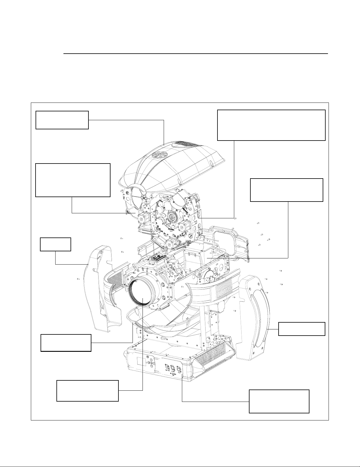
The following illustration shows the major sub-assemblies which are located in the luminaire head and
yoke assemblies.
Head Cover
(attached by tether)
Color Module Assembly
Contains fixed color wheels,
dimmer mechanism, strobe
mechanism, CYM color mixer
and CTO color correction.
Yoke Arm
Cover
Shutter/Gobo/Animation Assembly
Contains two rotating gobo / effects wheels,
four-blade shutter mechanism, two rotating
animation sheels, and iris mechanism
Backend Assembly
Houses lamp, reflector, and
UV/IR assembly.
Y oke Arm Cover
Head Cover
(attached by tether)
Spot Optics Assembly
Houses zoom lenses
and edge mechanisms.
02.9704.0010 0 7
Enclosure Assembly
see page 8
Page 26
VARI❋LITE - VL4000 SPOT LUMINAIRE SERVICE MANUAL
Enclosure Components
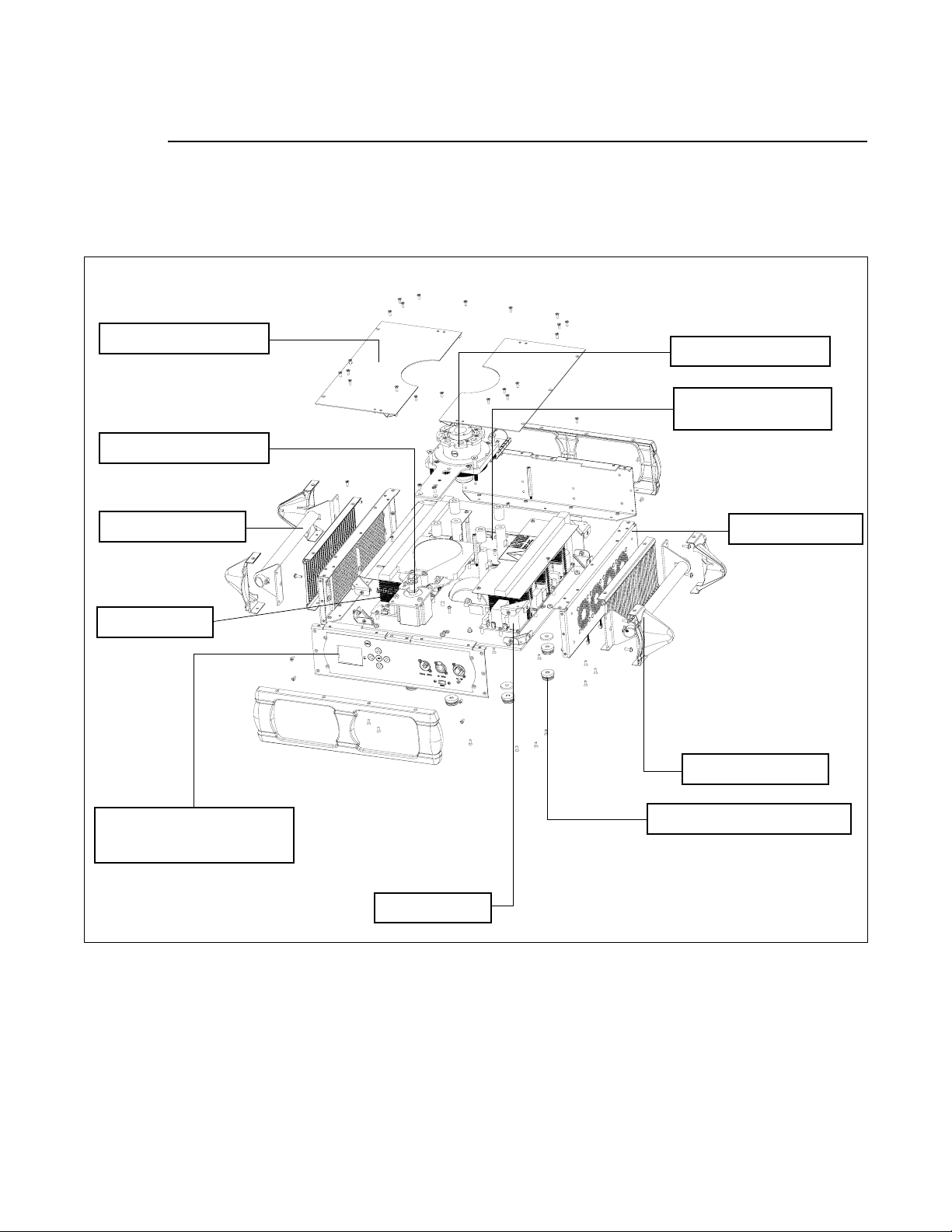
The following illustration shows the major sub-assemblies which are located in the luminaire
enclosure assembly. (Yoke and head assemblies not shown for clarity.)
Enclosure Top Covers
Pan Motor Assembly
Enclosure Handle
Lamp Driver
Pan Tube Assembly
36 VDC / Low-Voltage
Power Supply
Fan Assembly
Enclosure Handle
Input Panel Assembly
Contains DMX Input, PCB
AC Input, and Menu Display
PFC Supply
8 02.9704.0010 0
Bracket Mounting Buttons
Page 27

CHAPTER 2.
Rountine Maintenance
This chapter contains test, service, and standard maintenance procedures.
• Troubleshooting
• Routine Maintenance Procedures
Note: This manual is a preliminary release version. Additional maintenance
procedures and information will be released in an updated version of the manual.
WARNING: All maintenance procedures are to be performed with power
removed from the luminaire. Never remove cover or backcap while lamp is in operation.
WARNING: Maintenance, repairs, and adjustments should only be performed by
a qualified, factory-trained service technician at an Authorized VARI❋LITE
Service Center.
02.9704.0010 0 9
Page 28

VARI❋LITE - VL4000 SPOT LUMINAIRES SERVICE MANUAL
Troubleshooting
Error Messages
If a problem occurs during luminaire calibration, at the end of the calibration sequence the Menu
Display will cycle through any applicable error message(s) until the end of the list is reached. To
review the error messages again, it will be necessary to access them using the Status function.
To access error messages:
Step 1. Press [ESC].
Step 2. Press [Up] / [Down] arrows until Fixture appears. Press [OK].
Step 3. Press [Up]/ [Down] arrows to access Status. Press [OK]. (Display will now scroll through
any error messages or display OK if no errors).
Table 2-1: Error Messages
Display Meaning
OK No Errors Found - All Sensors Responded Properly
Pan Sensor Pan Senso r (Encoder) Error
Tilt Sensor Tilt Sensor (Encoder) Error
Dimmer Sensor Dimmer Sensor Error
Cyan Sensor Cyan Color Sensor Error
Yellow Sensor Yellow Color Sensor Error
Magenta Sensor Magenta Color Sensor Error
CTO Sensor CTO Sensor Error
Color Whl1 Sensor Color Wheel 1 Sensor Error
Color Whl2 Sensor Color Wheel 2 Sensor Error
Gobo Whl1 Sensor Rotating Gobo Wheel 1 Sensor Error
Gobo 1 Index Sensor Rotating Gobo Wheel 1 Indexing Sensor Error
Gobo Whl2 Sensor Rotating Gobo Wheel 2 Sensor Error
Gobo 2 Index Sensor Rotating Gobo Wheel 2 Indexing Sensor Error
Animation Whl1 Sensor Animation Wheel 1 Sensor Error
Animation 1 Index Sensor Animation Wheel 1 Indexing Sensor Error
Animation Whl2 Sensor Animation Wheel 2 Sensor Error
Animation 2 Index Sensor Animation Wheel 2 Indexing Sensor Error
Prism Sensor Prism Mechanism Sensor Error
Prism Rotate Sensor Prism Rotating Sensor Error
Prism Diverge Sensor Prism Diverge Sensor Error
Frost Sensor Frost Mechanism Sensor Error
Frost Adjust Sensor Frost Adjustment Sensor Error
Zoom Sensor Zoom Assembly Sensor Error
10 02.9704.0010 0
Page 29
TROUBLESHOOTING : TROUBLESHOOTING GUIDE
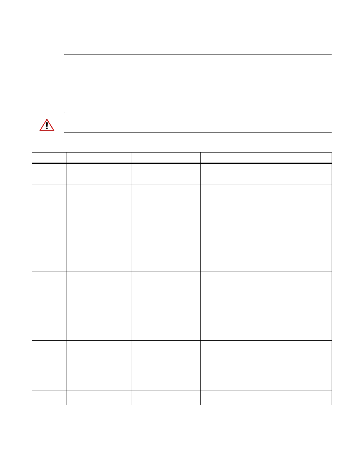
Troubleshooting Guide
If a problem is suspected, try recalibrating the luminaire to prompt an error message. If a problem is
suspected, first try recalibrating the luminaire to prompt an error message (refer to “Error Messages”
on page 10). The chart below provides possible causes and remedies for various error messages and/or
symptoms.
CAUTION: Some troubleshooting is included for reference only. Performing remedies may void
product warranty. Refer to the Vari-Lite Limited Warranty card included with the product.
Table 2-2: Troubleshooting Guide
Message Symptom Description Possible Cause/Remedy
Lamp
Power
Douse
n/a Lamp douses frequently Lamp Douse Fan failure...
n/a Lamp will not strike Lamp Strike Failure Lamp cutout switch disengag ed...
n/a Luminaire behaves
n/a Luminaire does not
n/a Self tests will not run or
n/a No response to DMX
Lamp does not strike
upon start-up
oddly
power up
software download does
not work from luminaire.
data
Lamp Off option is configured
DMX Map Not Matched Console library not set correctly...
No power Circuit not energized...
DMX Data Input Detecting DMX data...
DMX Failure DMX connector disconnected...
- Reconfigure lamp startup option in Lamp config
menu.
- check head and enclosure fans for proper
operation.
Ballast overheating...
- operating within the specified ambient
temperature?
- check enclosure vents for debris / dirt.
- check fan settings in menu.
- check enclosure fans for proper operation.
NOTE: Upon initial power up, ballast fans will run for
a few seconds and then operate as needed.
Enclosure vents must be clear of debris and dirt to
allow proper airflow.
- check lamp cutout switches at lamp box and fan
ducts.
Bad lamp...
- replace lamp.
Low input voltage...
- check input power (must be 200 to 240 VAC).
- check console library matches DMX map of
luminaire.
- verify circuit breaker (at source) is turned on.
Not plugged in...
- ensure A/C cable is connected to power source.
- disconnect DMX input cable.
- check DMX DATA IN connection.
2
02.9704.0010 0 11
Page 30

VARI❋LITE - VL4000 SPOT LUMINAIRES SERVICE MANUAL
Message Symptom Description Possible Cause/Remedy
n/a Erratic control of
luminaire
DMX Termination No DMX termination or termination not correct...
- check for DMX terminator.
- Luminaire DMX address does not match console
patch.
12 02.9704.0010 0
Page 31
ROUTINE MAINTENANCE PROCEDURES : LAMP REMOVAL AND INSTALLATION
Routine Maintenance Procedures
WARNING: As with any repairs or maintenance to VARI❋LITE luminaires, service should only be
performed by a trained and qualified service technician or at an Authorized VARI❋LITE Service
facility.
Lamp Removal and Installation
WARNING: Disconnect fixture before relamping. Déconnectez le projecteur avant que le
changement de lampe.
CAUTIONS & WARNINGS
• Wear cotton gloves or other covering while installing lamp. Touching lamp glass with bare fingers
will leave oil and may cause the lamp to explode or reduce lamp life. If touched, use isopropyl
alcohol and cotton cloth to thoroughly clean glass portion of lamp.
2
• Hot Lamp. Luminaire must remain powered on for 5 minutes after dousing lamp. Do not open for
5 minutes after switching off. Lampe chaude. Le luminaire doit rester en marche pendant 5
minutes après avoir éteindre la lampe. Ne pas ouvrir pendant 5 minutes après la coupure.
• Risk of exposure to excessive ultraviolet radiation. Do not operate without complete lamp
enclosure in place or when lens is damaged. Risque d’exposition aux rayonnements ultraviolets
excessifs. Ne pas faire fonctionner sans le boîtier complet de lampe mis en place ou lorsque
l’objectif est endommagé.
To replace lamp:
Step 1. Ensure power is completely removed from luminaire.
Step 2. Set the luminaire head horizontally.
Step 3. Engage tilt lock to secure luminaire head in position.
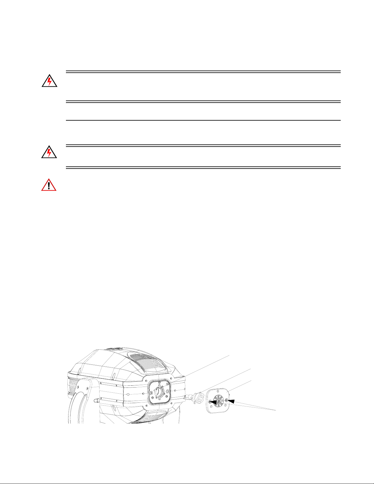
Step 4. At back of luminaire, using #2 Phillips screwdriver, remove lamp socket cover by loosening
the two quarter-turn captive screws. Note: lamp socket cover is connected with a safety
tether.
Lamp Socket
Lamp
Lamp Socket Cover
Quarter-Turn Screws
Figure 2-1: Lamp Socket Cover Removal
02.9704.0010 0 13
Page 32
VARI❋LITE - VL4000 SPOT LUMINAIRES SERVICE MANUAL
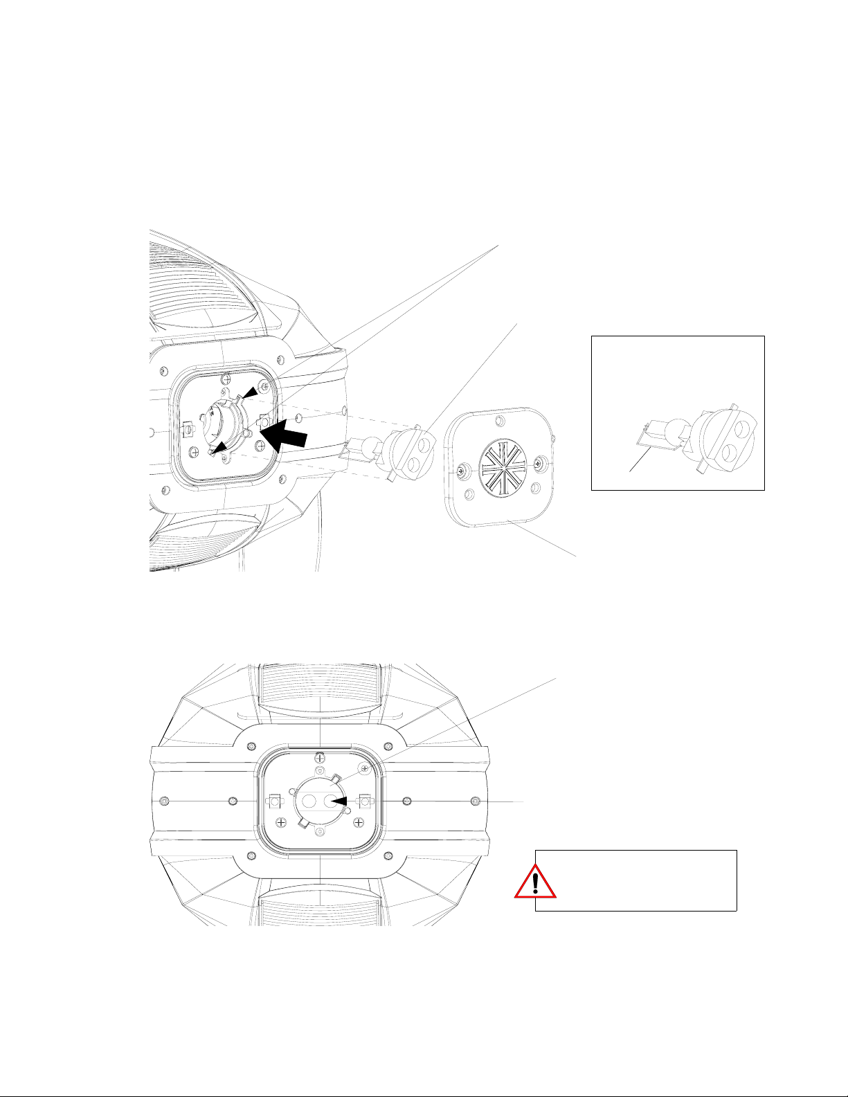
Step 5. To remove lamp, grasp lamp base by hand, twist lamp counter-clockwise until lamp’s tabs
align with slots in lamp socket (see Figure 2-2 on page 14 for more information), and
remove lamp by pulling it straight out of socket.
Step 6. Remove replacement lamp from shipping box.
Step 7. As shown in Figure 2-2, align replacement lamp tabs with lamp socket.
Align tabs of lamp with
socket when installing
Lamp*
NOTE: * "Bow" of lamp must
be oriented with "Slot" in
reflector.
Bow
Lamp Socket Cover
Figure 2-2: Lamp Installation
Step 8. Install lamp fully into lamp socket, taking care not to touch lamp glass.
Step 9. Turn lamp clockwise to seat lamp into socket. Lamp base should be aligned as illustrated in
Figure 2-3.
Lamp
Note alignment of fully seated lamp
Ensure lamp is completely
seated before reinstalling lamp
socket cover.
Figure 2-3: Installed Lamp
Step 10. Reinstall lamp socket cover. Make sure safety tether is completely encapsulated within lamp
socket cover.
14 02.9704.0010 0
Page 33

ROUTINE MAINTENANCE PROCEDURES : LAMP REMOVAL AND INSTALLATION
Step 11. Disengage tilt lock to allow luminaire head to move freely.
Step 12. Align lamp as described in “Align Lamp For Maximum Beam Irradiance” on page 19.
2
02.9704.0010 0 15
Page 34
VARI❋LITE - VL4000 SPOT LUMINAIRES SERVICE MANUAL
Fixed Color Wheel Filter Removal and Installation
To remove and replace fixed color filters:
Step 1. Before removing power from luminaire, move Edge towards front of luminaire with control
console or via luminaire menu system.
WARNING: Remove power from luminaire and allow luminaire to cool completely before
performing this procedure.
Step 2. Remove power from luminaire and allow luminaire to cool completely.
Step 3. Depending on which color filter wheel you need to access, do the following:
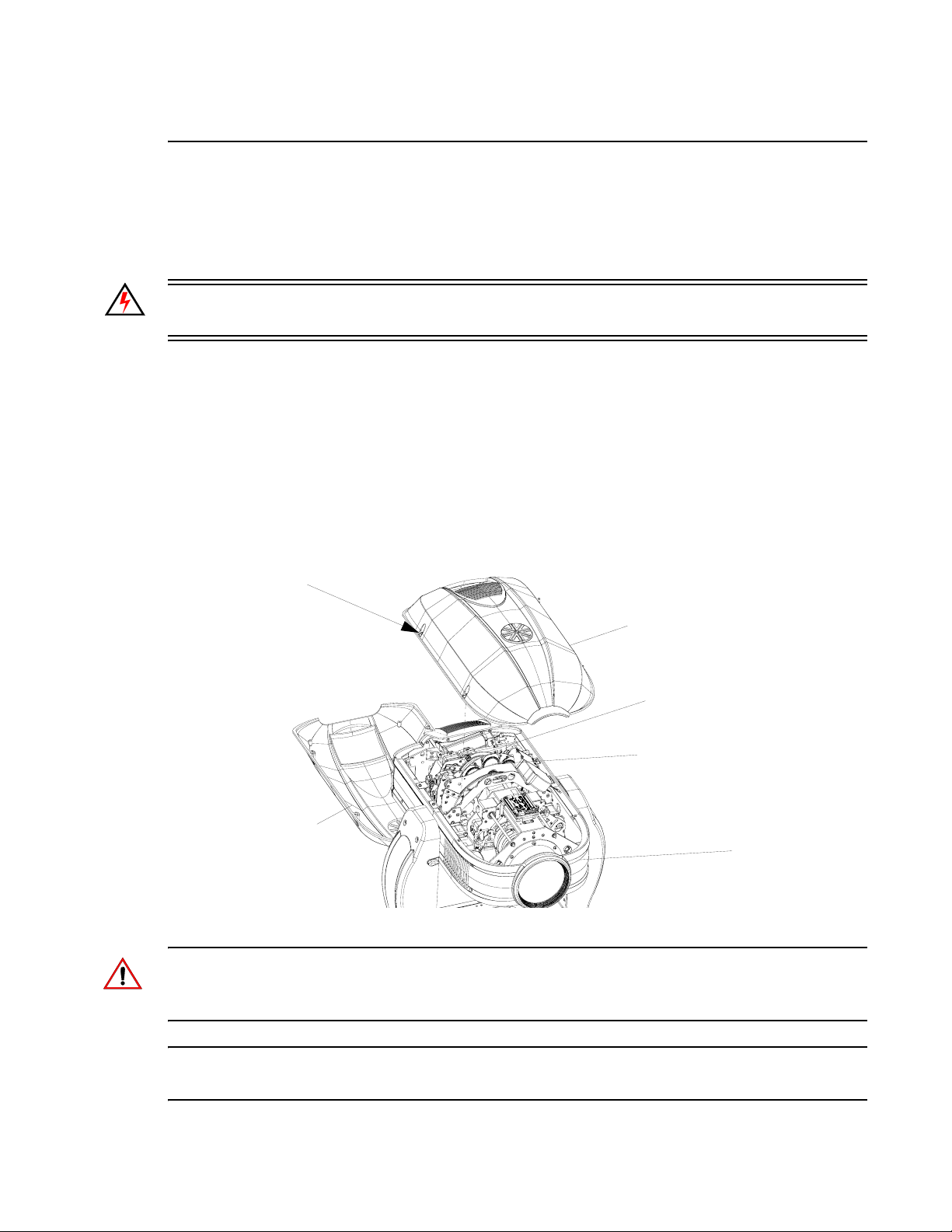
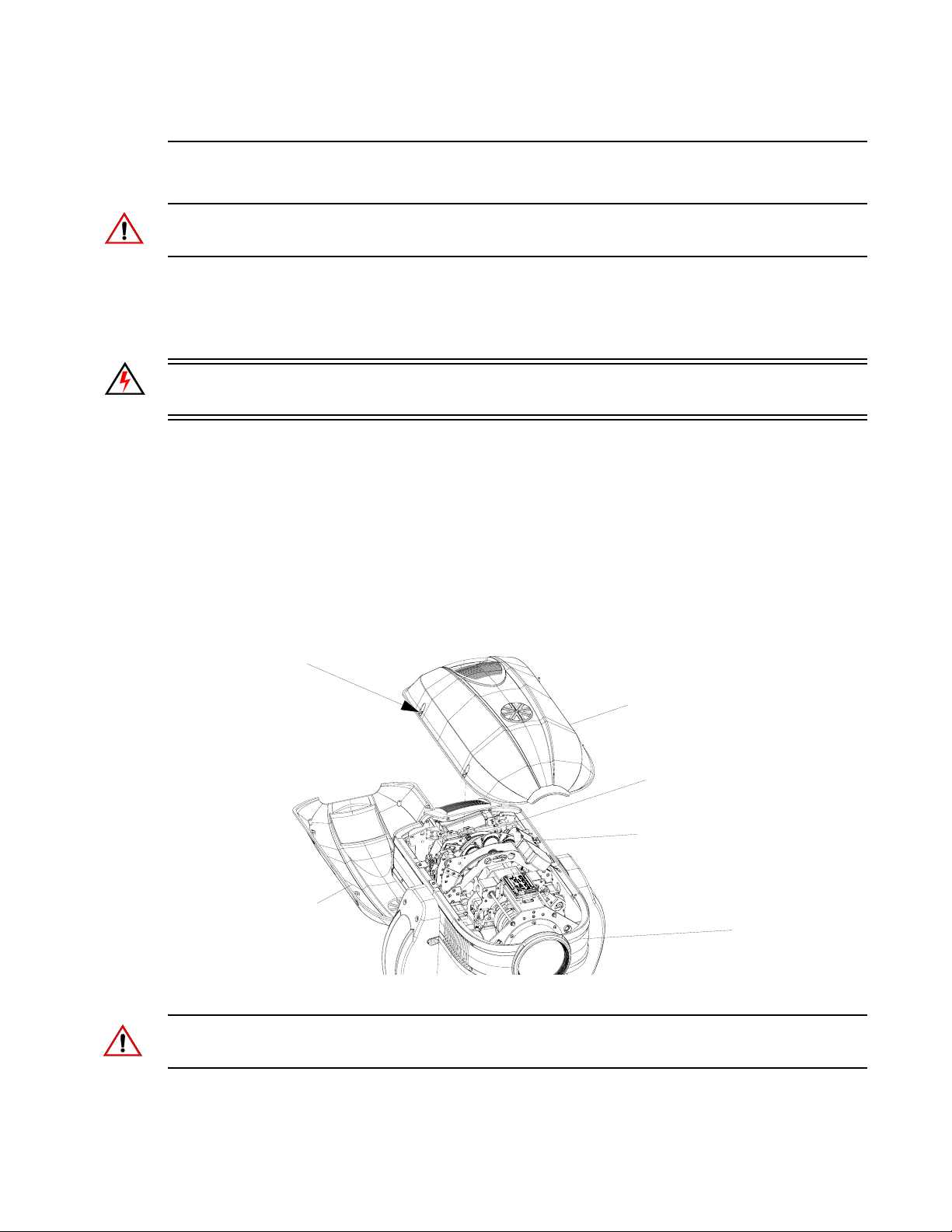
a. For Fixed Color Wheel 1 (closest to the rear of luminaire), remove head cover assembly
as indicated in Figure 2-4 by loosening four captive screws and lifting cover away from
luminaire head. Note, head cover is attached by a safety tether.
b. For Fixed Color Wheel 2 (closest to the front of luminaire), remove head cover
assembly as indicated in Figure 2-4 by loosening our captive screws and lifting cover
away from luminaire head. Note, head cover is attached by a safety tether.
Captive Phillips
Screws (x4)
Head Cover Assembly
to access Color Wheel 1*
* Each head cover is secured with a tether.
Head Cover Assembly
to access Color Wheel 2*
CYM / Fixed Color Assembly
(closest to lamp)
Shutter / Rotating Gobo Assembly
(closest to front lens)
Luminaire Head
Assembly
Figure 2-4: Replacing Fixed Color Filters
CAUTION: Wear protective gloves or other protective covering while handling filters to avoid
leaving fingerprints. Filters are extremely fragile and can break if not handled carefully. If dirty, clean
with isopropyl alcohol and a soft, lint-free cloth.
Note: For standard fixed color filters, refer to “Fixed Color Wheel 1” on page 28 or “Fixed Color
Wheel 2” on page 29
16 02.9704.0010 0
Page 35
ROUTINE MAINTENANCE PROCEDURES : FIXED COLOR WHEEL FILTER REMOVAL AND INSTALLATION
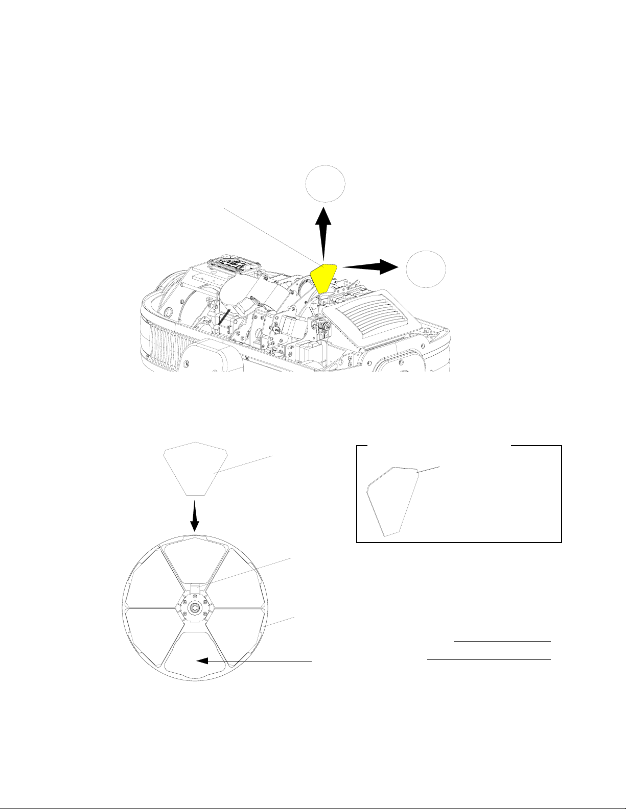
Step 4. At fixed color wheel, slowly rotate wheel by hand until filter to be removed is visible on
assembly as shown in Figure 2-5.
Step 5. At filter to be removed, (1) press filter out of fixed color wheel with fingers and (2) guide
filter up and away from fixed color wheel.
Pull filter straight up and away
from wheel assembly
2
Fixed Color Filter
Push filter from front
of wheel to dislodge it
1
from wheel assembly
2
Figure 2-5: Removing Fixed Color Filters
Step 6. Install replacement filter into slot. Note orientation of fixed color filter as indicated in Figure
2-6. Make sure filter is inserted and secured by fixed color wheel retaining clip as shown in
Figure 2-6.
Fixed Color Filter Orientation
Fixed Color Filter
Fixed Color Filter
VERY IMPORTANT!
Rear of filter is the REFLECTIVE
side and MUST be towards
lamp.
Fixed Color Filter Retaining Clip
Fixed Color Wheel Assembly
Note:
Open Position
(no filter)
Assembly shown for clarity.
Figure 2-6: Installing Fixed Color Filters
Step 7. After filter is installed, reinstall head cover(s).
02.9704.0010 0 17
Page 36
VARI❋LITE - VL4000 SPOT LUMINAIRES SERVICE MANUAL
Rota ting Gobo Removal and Installation
CAUTION: VL4000 Spot Luminaires accept glass gobos only. Use of metal gobos in these
luminaires may damage gobo assembly and will void the luminaire warranty.
To remove and replace rotating gobos:
Step 1. Before removing power from luminaire, move Edge towards front of luminaire with control
console or via luminaire menu system.
WARNING: Remove power from luminaire and allow luminaire to cool completely before
performing this procedure.
Step 2. Remove power from luminaire and allow luminaire to cool completely.
Step 3. Depending on which rotating gobo wheel you need to access, do the following:
a. For Rotating Gobo Wheel 1 (closest to the rear of luminaire), remove head cover
assembly as indicated in Figure 2-4 by loosening our captive screws and lifting cover
away from luminaire head. Note, head cover is attached by a safety tether.
b. For Rotating Gobo Wheel 2 (closest to the front of luminaire), remove head cover
assembly as indicated in Figure 2-4 by loosening our captive screws and lifting cover
away from luminaire head. Note, head cover is attached by a safety tether.
Captive Phillips
Screws (x4)
Head Cover Assembly
to access Rotating
Gobo Wheel 1*
* Each head cover is secured with a tether.
Head Cover Assembly
to access Rotating Gobo Wheel 2*
CYM / Fixed Color Assembly
(closest to lamp)
Shutter / Rotating Gobo Assembly
(closest to front lens)
Luminaire Head
Assembly
Figure 2-7: Replacing Rotating Gobos
CAUTION: Wear protective gloves or other protective covering while handling gobos to avoid
leaving fingerprints. If dirty, clean with isopropyl alcohol and a soft, lint-free cloth.
18 02.9704.0010 0
Page 37
ROUTINE MAINTENANCE PROCEDURES : ROTATING GOBO REMOVAL AND INSTALLATION
2
Note: For the standard load of rotating gobos, refer to “Rotating Gobo Wheel 1” on page 30 or
“Rotating Gobo Wheel 2” on page 31
Step 4. At rotating gobo wheel, slowly rotate wheel by hand until gobo to be removed is visible on
assembly.
Step 5. Grip gobo assembly and pull up to remove from luminaire head.
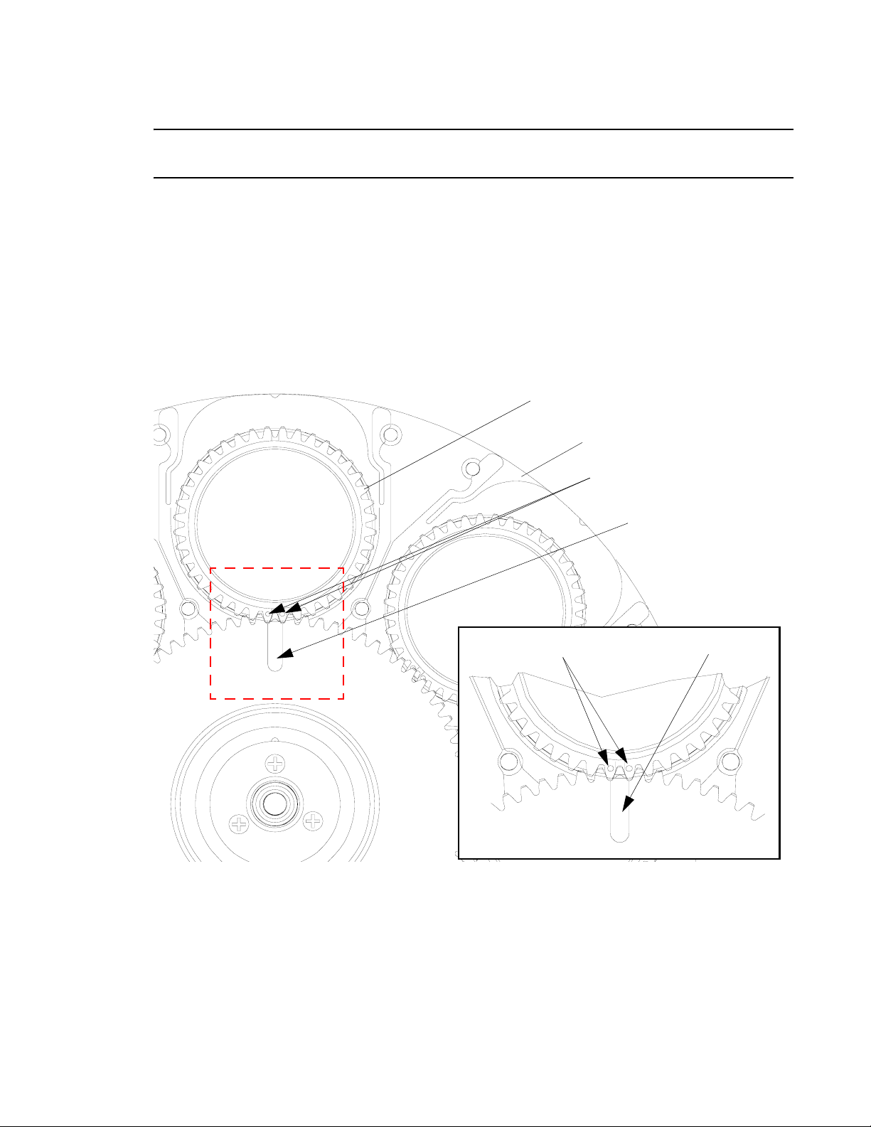
Step 6. Before installing gobo assembly into rotating gobo wheel assembly, make note of
relationship between carrier and main gear slot as illustrated in Figure 2-8.
a. Align gobo assembly gear timing marks WITH...
b. Slot in main gear on gobo wheel assembly. You may have to rotating gear by hand for
alignment.
Rotating Gobo Assembly
Rotating Gobo Wheel Assembly
Timing Marks Slot
Figure 2-8: Rotating Gobo Wheel - Gobo Clocking
(a) Align gobo assembly timing
marks with...
(b) Slot in main gear in
gobo wheel assembly
- Continued Next Page -
02.9704.0010 0 19
Page 38
VARI❋LITE - VL4000 SPOT LUMINAIRES SERVICE MANUAL
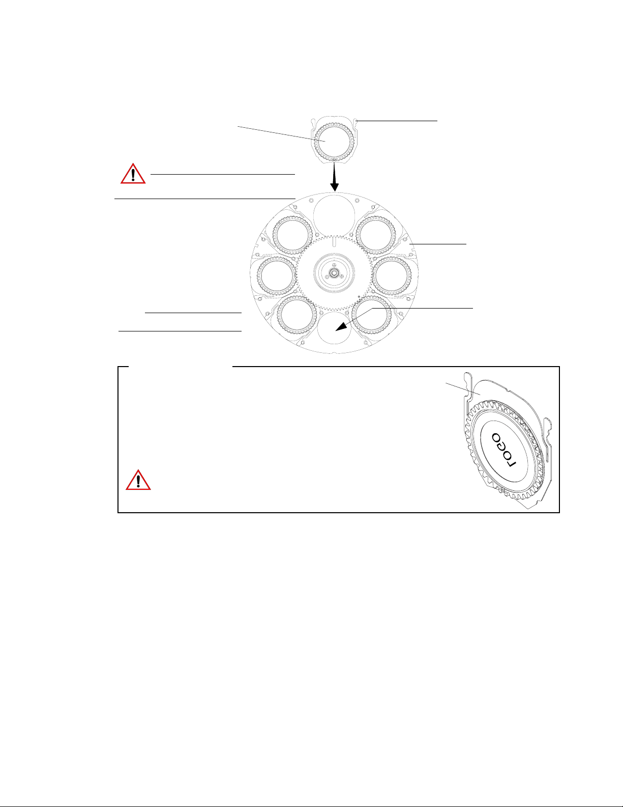
Rotating Gobo Assembly
(gear side towards front of
luminaire)
Do not touch glass with bare fingers.
CAUTION:
Front of Assembly Shown
(side towards front lens)
Note:
Assembly shown for clarity.
Assembly Orientation
Handle by gobo carrier only.
Rotating Gobo
Retaining Tabs
(Retaining clips need to be
seated in pins but are not
used to aid in removal)
Rotating Gobo
Wheel Assembly
Open Position
(no gobo)
Rotating Gobo Assembly
VERY IMPORTANT!
Side shown (to right) is non-reflective side. The non-reflective side
must face the front lens.
Rear of gobo is the REFLECTIVE side and MUST be towards lamp.
VL4000 Spot Luminaires accept glass gobos only. Use of metal
gobos in these luminaires may damage gobo assembly and will void
the luminaire warranty.
Figure 2-9: Rotating Gobo Wheel - Gobo Installation
Step 7. After ensuring main gear slot and gobo assembly timing marks are properly aligned (as
described in Step 7, install replacement rotating gobo assembly into gobo position. Note
orientation of rotating gobo assembly as indicated in Figure 2-9.
Step 8. After rotating gobo assembly is installed, reinstall head cover(s).
20 02.9704.0010 0
Page 39
ROUTINE MAINTENANCE PROCEDURES : ANIMATION WHEELS REMOVAL AND INSTALLATION
Animation Wheels Removal and Installation
To remove and replace anim atio n wheels:
Step 1. Before removing power from luminaire, move Edge towards front of luminaire with control
console or via luminaire menu system.
WARNING: Remove power from luminaire and allow luminaire to cool completely before
performing this procedure.
Step 2. Remove power from luminaire and allow luminaire to cool completely.
Step 3. Depending on which animation wheel you need to access, do the following:
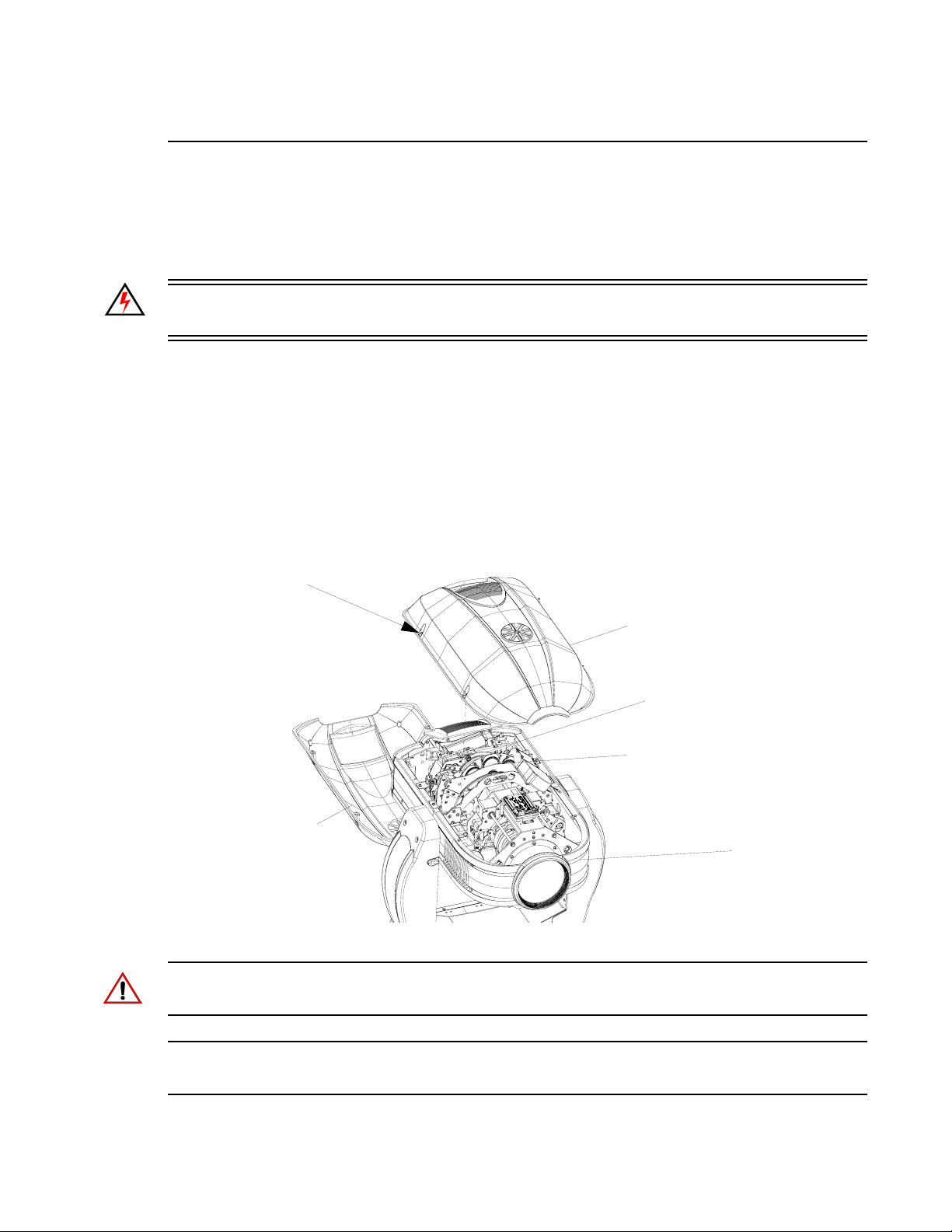
a. For Animation Wheel 1 (closest to the rear of luminaire), remove head cover assembly
as indicated in Figure 2-10 by loosening four captive screws and lifting cover away from
luminaire head. Note, head cover is attached by a safety tether.
b. For Animation Wheel 2 (closest to the front of luminaire), remove head cover assembly
as indicated in Figure 2-10 by loosening four captive screws and lifting cover away from
luminaire head. Note, head cover is attached by a safety tether.
2
Captive Phillips
Screws (x4)
Head Cover Assembly
to access Animation
Wheel 1*
* Each head cover is secured with a tether.
Head Cover Assembly
to access Animation Wheel 2*
CYM / Fixed Color Assembly
(closest to lamp)
Shutter / Rotating Gobo / Animation
Wheel Assembly
(closest to front lens)
Luminaire Head
Assembly
Figure 2-10: Replacing Animation Wheels
CAUTION: Wear protective gloves or other protective covering while handling animation wheels to
avoid leaving fingerprints. If dirty, clean with isopropyl alcohol and a soft, lint-free cloth.
Note: For the standard load of animation wheels, refer to “Animation Wheel 1 - Dichro*Fusion” on
page 32 or “DMX Operation” on page 33.
02.9704.0010 0 21
Page 40
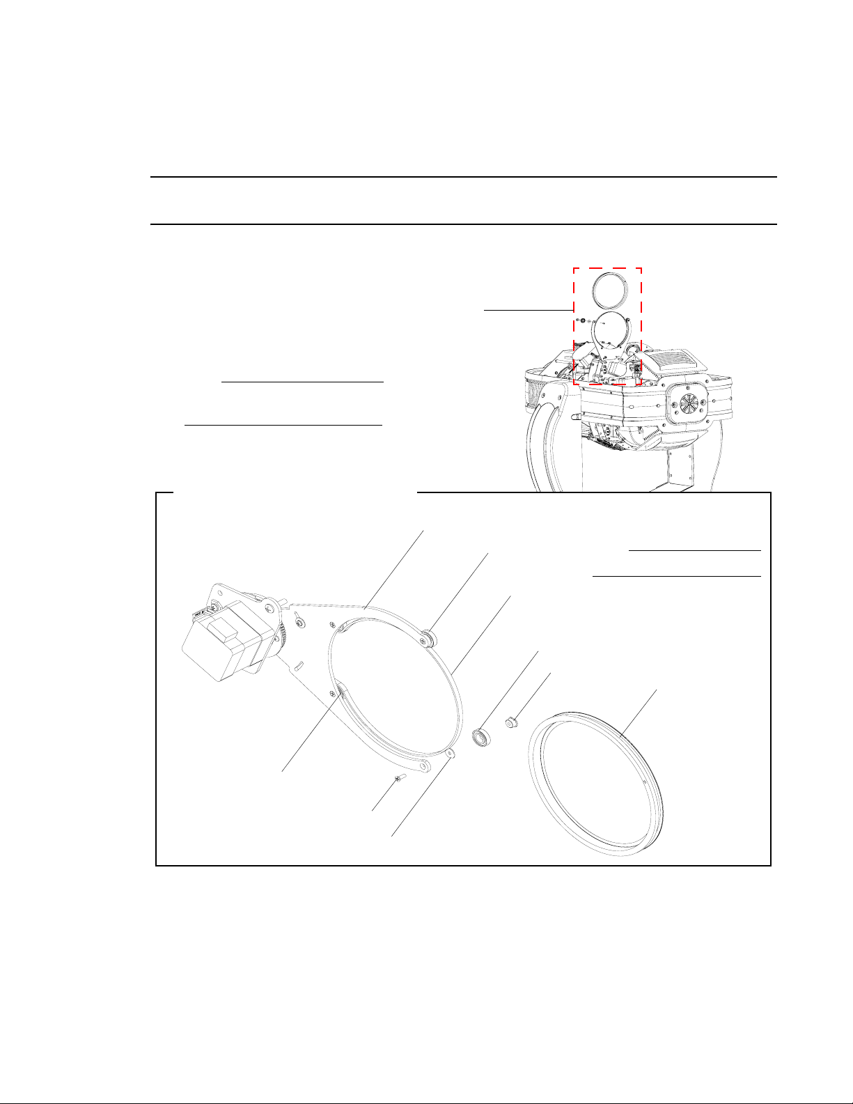
VARI❋LITE - VL4000 SPOT LUMINAIRES SERVICE MANUAL
Step 4. Loosen screw on bulkhead so animation arm can swing out
Step 5. Remove one screw from animation frame.
CAUTION: Be careful not to lose belt bearing, washer, screw or post. These will be required for
reassembly and installation.
Step 6. Slip belt off of animation wheel. Remove wheel.
See Detail
Note:
Animation wheel 2 shown.
Information same for both wheels.
Animation Wheel Assembly (Detail)
Belt Bearing
Bearing Screw
Bearing Washer
Figure 2-11: Animation Wheel Removal & Installation
Animation Wheel Assembly
Belt Bearing
Drive Belt
Belt Bearing
Bearing Post
Note:
Assembly shown for clarity.
Animation Wheel
Step 7. Slip belt around new wheel. Seat on all three bearin gs.
Step 8. Reassemble post onto bearing and washer. Hand tighten down with screw.
Step 9. Swing animation arm back into beam area and hand tighten down bulkhead screw.
Step 10. After animation wheel is installed, reinstall head cover(s).
22 02.9704.0010 0
Page 41
ROUTINE MAINTENANCE PROCEDURES : CLEANING OPTICAL LENSES AND FILTERS
2
Cleaning Optical Lenses and Filters
WARNING: Remove power from luminaire before performing maintenance.
WARNING: Acetone is a harsh cleaning agent and solvent. Acetone is very flammable. Please handle
acetone according to manufacturer’s safety instructions and precautions.
The front lens, optics/color filters, and reflector may require cleaning after extended use.
• FRONT LENS: Use a isopropyl alcohol with a soft, lint-free cloth to clean the front lens.
• OPTICS/COLOR FILTERS/ GOBOS/ANIMATION WHEELS: Use Acetone or Isopropyl
Alcohol along with a soft, lint-free cloth to clean the optics/color filters.
• REFLECTOR: Use Acetone or Isopropyl Alcohol along with a soft, lint-free cloth to clean the
reflector.
CAUTION: Do not continuously rub color filters or reflector - it may damage or remove the optical
coating.
02.9704.0010 0 23
Page 42

VARI❋LITE - VL4000 SPOT LUMINAIRES SERVICE MANUAL
Notes
24 02.9704.0010 0
Page 43

CHAPTER 3.
Illustrated Parts Breakdown
This chapter contains illustrated parts breakdowns for all VL4000 Spot Luminaire assemblies.
• Drawing Trees
• Principle of Operation
• Top Assembly
• Head Assembly
• Yoke Assembly
• Enclosure Assembly
• Cable Assemblies
02.9704.0010 0 25
Page 44
VARI❋LITE - VL4000 SPOT LUMINAIRE SERVICE MANUAL
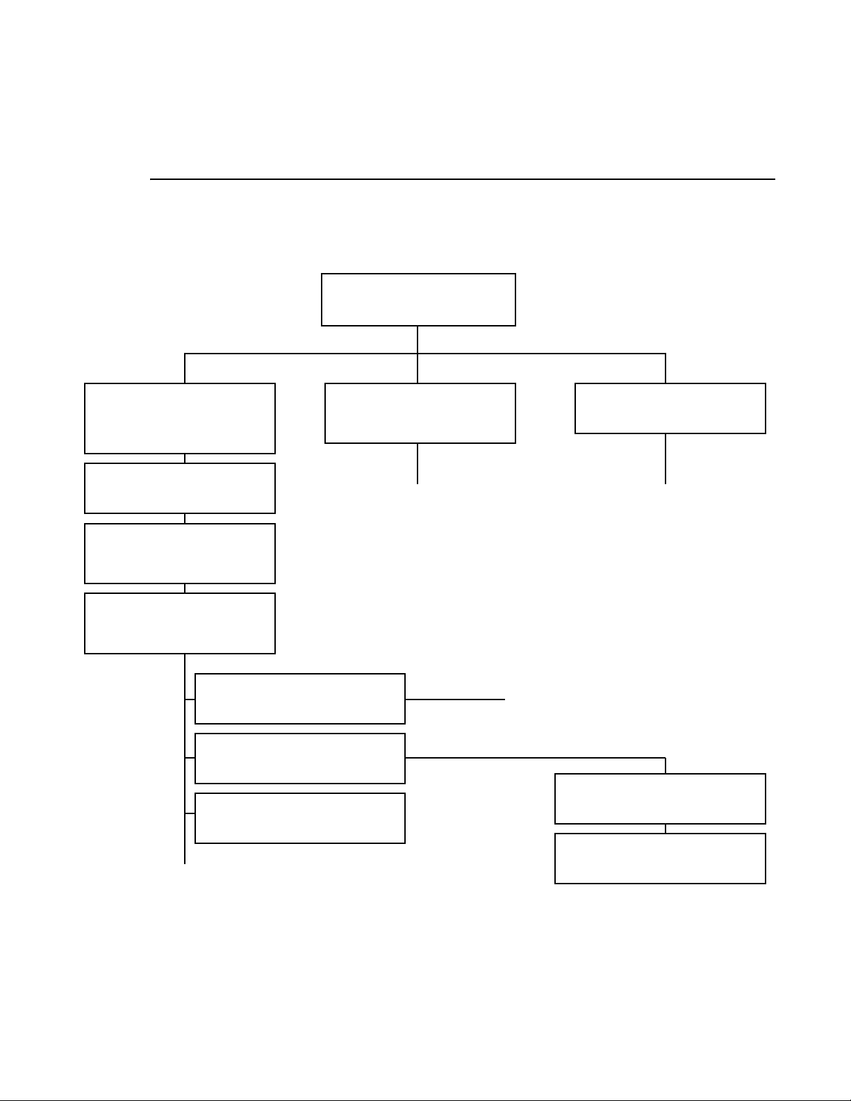
Drawing Trees
VL4000 Spot Luminaire (Part 1)
VL4000 Spot Luminaire
20.9704.0001 Rev. E
Included Items Kit, VL4000 Spot
28.9704.0001 Rev. B
(note, this item includes all included/
standard gobos)
VL4000 Head Cover Assembly
22.9704.0670 Rev. A
VL4000 Yoke Arm Cover
Assembly
22.9704.0732 Rev. A
VL4000 Generic Luminaire
Assembly
21.9704.0010 Rev. R
Head Frame Assembly
21.9704.0600 Rev. K
Yoke Assembly
21.9704.0700 Rev. K
Stabilizer Assembly
21.9704.1767 Rev. A
Shutter/Gobo/Animation Module
Assembly
21.9704.4400 Rev. H
Continued on “VL4000 Spot
Luminaire (Part 4)” on page 29.
Color Module Assembly
21.9704.0200 Rev. N
Continued on “VL4000 Spot
Luminaire (Part 6)” on page 31.
Continued on “VL4000 Spot
Luminaire (Part 2)” on page 27.
Tilt Motor Assembly
21.9704.0700 Rev. K
Tilt Motor with Pulley Assembly
21.9704.0764 Rev. A
Continued on “VL4000 Spot
Luminaire (Part 2)” on page 27.
Figure 3-1: VL4000 Spot Luminaire Subassembly Drawing Tree Part 1
26 02.9704.0010 0
Page 45
DRAWING TREES : VL4000 SPOT LUMINAIRE (PART 2)
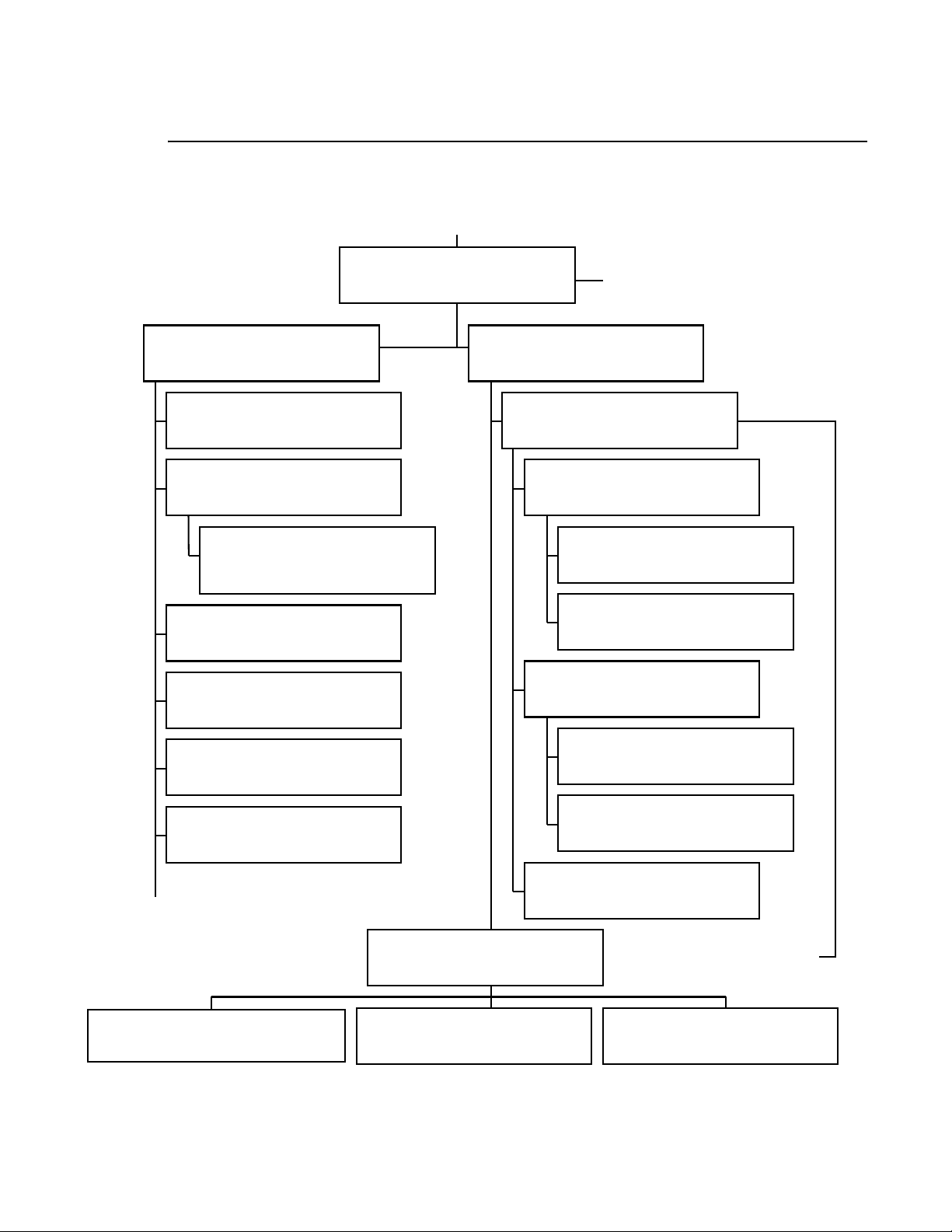
VL4000 Spot Luminaire (Part 2)
Continued from “VL4000 Spot Luminaire (Part 1)” on page 26.
3
VL4000 Generic Luminaire Assembly
Upper Enclosure Assembly
21.9704.0800 Rev. U
Side Mount Fan Assembly
21.9704.0810 Rev. D
Front Panel Assembly
21.9704.0825 Rev. G
VL4000 AC Input Connector
Assembly
25.9704.0830 Rev. A
Pan Bearing / Pulley Assembly
21.9704.0840 Rev. F
Pan / Fan Driver Board Assembly
21.9704.0870 Rev. G
21.9704.0010 Rev. R
Continued on “VL4000 Spot
Luminaire (Part 3)” on page 28.
Head Frame Assembly
21.9704.0600 Rev. K
VL4000 Zoom Spot Assembly
21.9704.0150 Rev. K
Prism Motor Assembly
21.9704.0134 Rev. F
Prism Assembly
21.9704.0115 Rev. C
Slotted Optical Switch
25.9687.0020 Rev. A
Frost Motor Assembly
21.9704.0135 Rev. H
Pan Module Assembly
21.9704.1820 Rev. G
Upper Enclosure Cover Assembly
21.9704.0850 Rev. A
Lens Group 3 Motor Assembly
Frost Flag Assembly
21.9704.0136 Rev. C
Slotted Optical Switch
25.9687.0020 Rev. A
21.9704.0155 Rev. A
Continued on “VL4000 Spot
Luminaire (Part 3)” on page 28.
Back End Assembly
21.9704.1615 Rev. G
Continued on “VL4000
Spot Luminaire (Part 5)” on
page 30.
VL4000 Lamp Socket Cable Assembly
25.9701.2701 Rev. A
Reflector Assembly
21.9704.0619 Rev. A
Lamp Cover Assembly
21.9704.0632 Rev. B
Figure 3-2: VL4000 Spot Luminaire Subassembly Drawing Tree Part 2
02.9704.0010 0 27
Page 46
VARI❋LITE - VL4000 SPOT LUMINAIRE SERVICE MANUAL
VL4000 Spot Luminaire (Part 3)
Continued from “VL4000 Spot Luminaire (Part 2)” on page 27.
VL4000 Generic Luminaire Assembly
21.9704.0010 Rev. R
LVS Chassis Ground Cable Assembly
25.9687.0025 Rev. A
Upper Enclosure Assembly
21.9704.0800 Rev. U
VL4000 USB Interface Cable
Assembly
25.9704.0804 Rev. A
VL4000 Thermal Control Cable
Assembly
25.9704.1805 Rev. A
VL4000 Chassis to Yoke Cable
Assembly
25.9704.0716 Rev. B
VL4000 Ballast to Ignitor Cable
Assembly
25.9704.0702 Rev. A
VL4000 Pan / Tilt Cable Assembly
25.9704.1703 Rev. D
VL4000 Pan / Power Distribution
Input Cable Assembly
25.9704.2704 Rev. A
VL4000 Enclosure PFC Input Cable
Assembly
25.9704.1800 Rev. A
VL4000 Enclosure PFC Output Cable
Assembly
25.9704.1801 Rev. A
VL4000 Tilt Cable Assembly
25.9704.1717 Rev. A
VL4000 Color Power Distribution
Cable Assembly
25.9704.0708 Rev. D
VL4000 Main from MCB Data Cable
Assembly
25.9704.0713 Rev. C
VL4000 Main to Bulkheads Data
Cable Assembly
25.9704.0714 Rev. A
VL4000 Lamp Base & Tip Fan
Extension Cable Assembly
25.9704.1602 Rev. B
VL4000 Main Power Distribution
Cable Assembly
25.9704.1705 Rev. E
VL4000 DMX Cable Assembly
25.9704.0802 Rev. A
VL4000 Ballast Control Cable
Assembly
25.9704.0803 Rev. A
Figure 3-3: VL4000 Spot Luminaire Subassembly Drawing Tree Part 3
28 02.9704.0010 0
Page 47
DRAWING TREES : VL4000 SPOT LUMINAIRE (PART 4)
VL4000 Spot Luminaire (Part 4)
Continued from “VL4000 Spot Luminaire (Part 1)” on page 26.
VL4000 Spot Luminaire (Part 1)
20.9704.0001 Rev. E
Shutter/Gobo/Animation Module
Assembly
21.9704.4400 Rev. H
3
Gobo Wheel 1 Assembly
21.9704.0211 Rev. D
Gobo Wheel 2 Assembly
21.9704.0212 Rev. E
Gobo 1 Sensor Index Assembly
21.9704.0230 Rev. B
Gobo 2 Sensor Index Assembly
21.9704.0260 Rev. B
Edge Motor Assembly
21.9704.0255 Rev. A
Gobo Bulkhead Left Bracket
Assembly
21.9704.0281 Rev. C
Animation Wheel 1 Assembly
21.9704.1351 Rev. A
Animation Wheel 1 Motor
Assembly
21.9704.0331 Rev. B
Animation Wheel 2 Assembly
21.9704.1352 Rev. A
Animation Wheel 2 Motor
Assembly
21.9704.0332 Rev. B
Shutter Bulkhead with Rotation
Assembly
21.9704.1505 Rev. G
Shutter Module Assembly
21.9704.1510 Rev. M
Gobo Bulkhead Right Bracket
Assembly
21.9704.0282 Rev. C
Shutter Rotate Motor Assembly
Continued on “VL4000 Spot
Luminaire (Part 5)” on page 30.
21.9704.1523 Rev. A
Continued on “VL4000 Spot
Luminaire (Part 5)” on page 30.
Shutter Rotate Adjustable Roller
Arm Assembly
21.9704.1570 Rev. A
Figure 3-4: VL4000 Spot Luminaire Subassembly Drawing Tree Part 4
02.9704.0010 0 29
Page 48
VARI❋LITE - VL4000 SPOT LUMINAIRE SERVICE MANUAL
VL4000 Spot Luminaire (Part 5)
Continued from “VL4000 Spot Luminaire (Part 4)” on page 29.
Shutter/Gobo/Animation Module
Assembly
21.9704.4400 Rev. H
VL4000 Gobo Bulkhead 1 Cable
Assembly
25.9704.0200 Rev. A
VL4000 Gobo Bulkhead 2 Cable
Assembly
25.9704.0201 Rev. A
VL4000 Gobo Bulkhead 3 Cable
Assembly
25.9704.0202 Rev. A
VL4000 Data Network Extension
Cable Assembly
25.9704.0711 Rev. B
Continued from “VL4000 Spot Luminaire (Part 2)” on page 27.
VL4000 Zoom Spot Assembly
21.9704.0150 Rev. K
Shutter Bulkhead with Rotation
Assembly
21.9704.1505 Rev. G
Shutter Module Assembly
21.9704.1510 Rev. M
VL4000 Shutter 1 Cable Assembly
25.9704.1500 Rev. B
VL4000 Shutter 2 Cable Assembly
25.9704.1501 Rev. B
VL4000 Shutter 3 Cable Assembly
25.9704.1502 Rev. A
VL4000 Power Distribution
Output-Shutter Cable Assembly
25.9704.0709 Rev. D
VL4000 Optics Bulkhead 1 Cable
Assembly
25.9704.2100 Rev. A
VL4000 Optics Bulkhead 2 Cable
Assembly
25.9704.2101 Rev. A
VL4000 Optics Bulkhead 3 Cable
Assembly
25.9704.0104 Rev. A
VL4000 Optics Bulkhead 4 Cable
Assembly
25.9704.0105 Rev. A
VL4000 Optics-E to Optics-F Data
Cable Assembly
25.9704.0715 Rev. B
VL4000 Data Network Cable
Assembly
25.9704.0710 Rev. B
Figure 3-5: VL4000 Spot Luminaire Subassembly Drawing Tree Part 5
30 02.9704.0010 0
Page 49
DRAWING TREES : VL4000 SPOT LUMINAIRE (PART 6)
VL4000 Spot Luminaire (Part 6)
Continued from “VL4000 Spot Luminaire (Part 1)” on page 26.
VL4000 Spot Luminaire (Part 1)
20.9704.0001 Rev. E
Color Module Assembly
21.9704.0200 Rev. N
210 Groove Belt Assembly
VL4000 Color Bulkhead 1 Cable
Assembly
25.9704.0400 Rev. A
VL4000 Color Bulkhead 2 Cable
Assembly
25.9704.0401 Rev. A
VL4000 Color Bulkhead 3 Cable
Assembly
25.9704.0402 Rev. A
VL4000 Color Bulkhead 4 Cable
Assembly
25.9704.0403 Rev. A
VL4000 Data Network Extension
Cable Assembly
25.9704.0711 Rev. B
VL4000 Color A to Color B Cable
Assembly
25.9704.0712 Rev. A
Control Belt Idler Assembly
21.9704.5443 Rev. A
21.9704.0411 Rev. B
240 Groove Belt Assembly
21.9704.0412 Rev. B
Color Flags Sensor Board
21.9704.0440 Rev. B
Fixed Color Wheel Assembly
21.9704.0415 Rev. E
Fixed Color Wheel 1 Assembly
Fixed Color Wheel 2 Assembly
3
Assembly
21.9704.0430 Rev. C
21.9704.0435 Rev. D
Fixed Color Motor Assembly
21.9704.0419 Rev. A
Cross-Flow Blower Assembly
Left Strobe Assembly
21.9704.0431 Rev. G
21.9704.0420 Rev. E
Right Strobe Assembly
21.9704.0432 Rev. D
Figure 3-6: VL4000 Spot Luminaire Subassembly Drawing Tree Part 6
02.9704.0010 0 31
Page 50
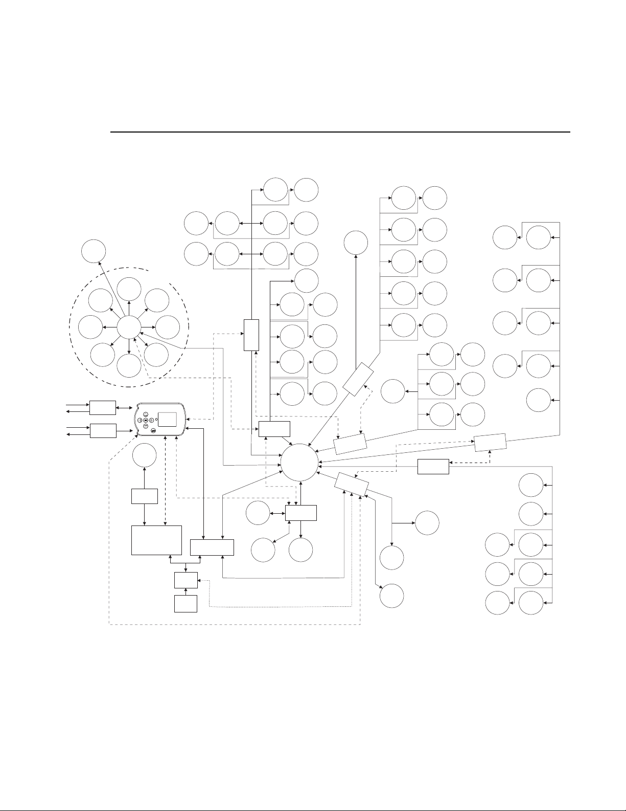
VARI❋LITE - VL4000 SPOT LUMINAIRE SERVICE MANUAL
Principle of Operation
VL4000 Spot Functional Block Diagram
VL4000 Spot
Luminaire Functional
Block Diagram
Iris
Mechanism
Shutter
Assembly
Shutter
Motor 1A
Shutter
Motor 4A
Shutter
Motor 4B
Shutter
Motor 3B
USB
Port
DMX Input /
Thru
COM
Driver
PCB
(9-Way)
Shutter
Motor 3A
Shutter
Motor 1B
Shutter
Motor 2A
Shutter
Motor 2B
Main Control Board
LCD
Display
Lamp
Socket
Lamp
Driver COM
Ignitor
Lamp Driver
Assembly
Sensor
Gobo
Index
Sensor
COM
COM
36VDC Low-Voltage
PFC
AC
Input
Rotating
Gobo 2
Rotating
Gobo 2
Index
COM
Supply Assembly
TEMPERATURE MEASUREMENT
PCB
Driver
(Gobo C)
Lamp Base
Fan / Lamp
Tip Fan
Tilt
Encoder
Shutter
Rotate
Rotating
Gobo 1
Rotating
Gobo 1
Index
Driver
PCB
(Gobo D)
COM
Animation
2
Animation
2 Index
Animation
1
Animation
1 Index
Distribution
(36VDC &
12VDC)
Power
Driver
PCB
(Tilt)
Motor
Shutter
Rotate
Sensor
Sensor
Gobo
Index
Sensor
Module
Cooling
COM
Tilt
Mechanism
Sensor
Rotate
Sensor
Diverge
Sensor
Mechanism
Sensor
Sensor
Driver
(Color A)
Enclosure
Fans (x4)
Prism
Prism
Prism
Frost
Frost
Adjust
Zoom
Motor
Edge
Motor
Condenser
Lens
Motor
PCB
Zoom Motor
Sensor
Edge
Motor
Condenser
Lens
Sensor
COM
Driver
PCB
(Color B)
Sensor
Dimmer
Fixed
Color Whl 1
Sensor
Fixed
Color Whl 2
Sensor
Yellow
Flags
Sensor
Magenta
Flags
Sensor
Cyan
Flags
Flags
Sensor
CTO
Flags
Sensor
Right
Strobe
Left
Strobe
Cyan
Flags
Dimmer
Flags
CTO
Flags
Fixed
Color
Wheel 1
Fixed
Color
Wheel 2
Yellow
Flags
Magenta
Flags
Cross
Blower
Prism
Mechanism
Prism
Mechanism
Back Inlet
Fan
COM
Pan
Motor
Pan
Encoder
Rotate
Prism
Diverge
Frost
Frost
Adjust
Front Inlet
Fan
Fan
Animation
2 Sensor
Animation
2 Index
Sensor
Animation
1 Sensor
Driver
PCB
Driver
PCB
(Optic F)
Driver
PCB
(Pan)
(Optic E)
COM
Animation
1 Index
Sensor
Note: Signal and driver lines shown for routing reference only. Lines
shown are not representative of actual cable assemblies.
32 02.9704.0010 0
Page 51

TOP ASSEMBLY : INCLUDED ITEMS KIT, VL4000 SPOT
Top Assembly
Included Items Kit, VL4000 Spot
28.9704.0001 Rev. B
Refer to Figure 3-7.
No. Item Qty. UM. Description
1 02.8001.0002 1 EA VARI-LITE QUALITY ASSURANCE CERT.
2 02.8052.0001 1 EA CARD, LIMITED WARRANTY
3 02.8406.0001 1 EA TAG, LAMP NOTICE
4 02.8700.0001 1 EA CARD, PRODUCT REGISTRATION
5 02.9704.0001 1 EA UNPACK/QUICK START SHEET, VL4000 SPOT
- 07.9686.0001 1 EA CARDBOARD SHIPPING BOX (not shown)
6 22.9704.0835 2 EA FAB ASSY, BRACKET TRUSS HOOK
7 25.9704.0862 1 EA POWERCON, NEUTRIK NAC3FX (TRUE1)
8 41.9704.4421 1 EA GOBO ASSY, ALPHA WAVES (POS 1-2)
9 41.9704.4422 1 EA GOBO ASSY, LEAFY BREAKUP (POS 1-3)
10 41.9704.4423 1 EA GOBO ASSY, NEURONS V2 (POS 1-4)
11 41.9704.5011 1 EA GOBO ASSY, NIGHT SKY (POS 1-5)
12 41.9704.4425 1 EA GOBO ASSY, BRICKED OUT (POS 1-6)
13 41.9704.8511 1 EA GAG ASSY, ON THE ROCKS (POS 1-7)
14 41.9704.8506 1 EA GAG ASSY, DROPLETS (POS 1-8)
15 41.9704.4411 1 EA GOBO ASSY, CIRCLE OF EIGHTS (POS 2-2)
16 41.9704.4412 1 EA GOBO ASSY, PUNCH CARD (POS 2-3)
17 41.9704.4413 1 EA GOBO ASSY, VERTICAL BARS (POS 2-4)
18 41.9704.4414 1 EA GOBO ASSY, LA TTICE (POS 2-5)
19 41.9704.4415 1 EA GOBO ASSY, WAVY TRIANGLE (POS 2-6)
20 41.9704.4416 1 EA GOBO ASSY, DOT BUFFET (POS 2-7)
21 41.9704.4291 1 EA GOBO ASSY, QUADCONE, RED (POS 2-8)
22 71.9704.1200 1 EA LAMP, 1200 WATT, PHILIPS MSR GOLD FASTFIT
3
02.9704.0010 0 33
Page 52
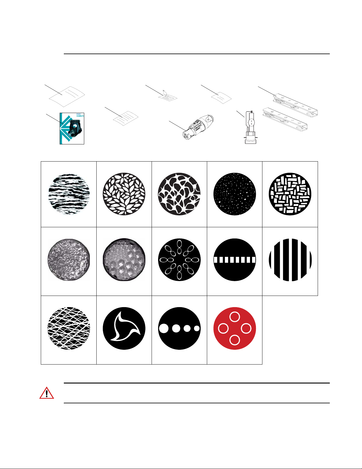
VARI❋LITE - VL4000 SPOT LUMINAIRE SERVICE MANUAL
Included Items Kit, VL4000 Spot (continued)
5
3
2
4
6
(x2)1
22*
7
VL4000 Spot Luminaire
QuickStart Guide
8
Alpha Rays
13 14 15 16 17
9
Leafy Breakup
10
Neurons V2
11
Night Sky
12
Bricked Out
On The Rocks Gag Droplets Gag Circle of Eights Punch Card Vertical Bars
18 19 20 21
Lattice Wavy Triangle Dot Buffet Quadcone, Red
Figure 3-7: Included Items Kit, VL4000 Spot
Note: * = Do not handle lamp with bare hands. When handling, it is best to wear clean cotton gloves
in order to keep the lamp’s glass as dirt and grease free as possible.
34 02.9704.0010 0
Page 53
TOP ASSEMBLY : VL4000 SPOT LUMINAIRE
VL4000 Spot Luminaire
20.9704.0001 Rev. E
Refer to Figure 3-8
No. Item Qty. UM. Description
1 10.9704.0641 2 EA FILTER, FOAM, HEAD INLET
2 10.9704.0671 1 EA HEAD COVER, REAR
3 10.9704.0672 2 EA FRONT SIDE RAIL COVER
4 10.9704.0673 2 EA HEAD COVER
5 21.9704.0010 1 EA ASSY, GENERIC LUMINAIRE, VL4000
6 21.9704.0200 1 EA ASSY, SHUTTER/GOBO/ANIMATION
7 21.9704.4400 1 EA ASSY, COLOR MODULE
8 22.9704.0670 2 EA VL4000 HEAD COVER
9 22.9704.0732 2 EA VL4000 YOKE ARM COVER
10 28.9704.0001 1 EA INCLUDED ITEM KIT, VL4000 SPOT (NOT SHOWN)
11 53.6543.0001 18 EA SCREW, 6-32 X 3/8" PPB
12 53.6614.0001 2 EA SCREW, 6-32 X 5/8" PPB
3
02.9704.0010 0 35
Page 54
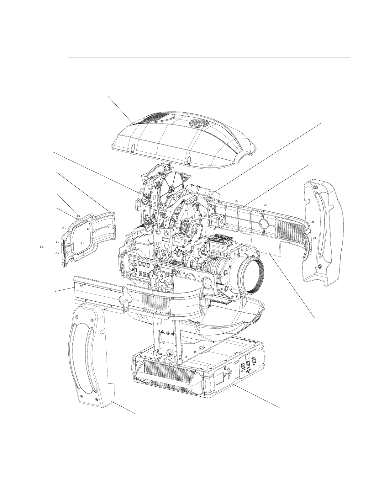
VARI❋LITE - VL4000 SPOT LUMINAIRE SERVICE MANUAL
VL4000 Spot Luminaire (continued)
8 (x2)
7
2
11 (x18)
12 (x2)
6
3 (x2)
4 (x2)
1 (x2)
9 (x2)
5
Figure 3-8: VL4000 Spot Luminaire
36 02.9704.0010 0
Page 55

TOP ASSEMBLY : VL4000 GENERIC LUMINAIRE ASSEMBLY
VL4000 Generic Luminaire Assembly
21.9704.0010 Rev. R
Refer to Figure 3-9
No. Item Qty. UM. Description
1 04.9704.0137 1 EA LABEL, LAMP CHANGE, 1200W FASTFIT
2 10.9704.0706 1 EA BEARING SPACER, SHORT
3 10.9704.0707 1 EA PULLEY, DRIVEN, TILT
4 10.9704.0711 1 EA TILT STOP
5 10.9704.0734 4 EA COVER MOUNT, YOKE ARM
6 10.9704.1712 2 EA TILT BEARING HOLDER
7 10.9704.1733 1 EA COVER, YOKE BASE
8 10.9704.1742 1 EA TILT LOCK CYLINDER
9 17.9704.1911 1 EA SENSOR BOARD, TILT
10 21.9704.0600 1 EA ASSY, HEAD FRAME
11 21.9704.0700 1 EA ASSY, YOKE
12 21.9704.0800 1 EA ASSY, UPPER ENCLOSURE, 1200W/1400W
13 21.9704.1767 1 EA ASSY, STABILIZER
- 25.9687.0025 1 EA CABLE ASSY, ENCLOSURE TO YOKE GND (not shown)
- 25.9704.1717 1 EA CABLE ASSY, VL4000 TILT (NOT SHOWN)
- 25.9704.0708 1 EA CABLE ASSY, VL4000 PWR DIST OUTPUT, COLOR (not shown)
- 25.9704.0713 1 EA CABLE ASSY, VL4000 DATA, MAIN FROM MCB (not shown)
- 25.9704.0714 1 EA CABLE ASSY, VL4000 DATA, MAIN TO BLKHDS (not shown)
- 25.9704.1602 1 EA CABLE ASSY, VL4000 FAN EXT, LAMP BASE & TIP (not shown)
- 25.9704.1705 1 EA CABLE ASSY, VL4000 PWR DIST OUTPUT, MAIN (not shown)
14 51-0369 16 EA SCREW, 8-32 X 1/4" PFZ
15 53.2202.0008 4 EA NUT, 8-32 HEX SS NYLON INSERT
16 53.5910.0375 6 EA SCREW, 10-32 X 1/2", PPSS TYPE F
17 53.6517.0625 5 EA SCREW, 10-32 X 5/8" PPZ
18 53.6521.0500 3 EA SCREW, 8-32 X 1/2" SOCKET, FLATHEAD, ALLOY STEEL
19 53.6525.0001 1 EA SCREW, 6-32 X 5/16" PPZ
20 53.6546.0002 4 EA SCREW, 8-32 X 5/16" PPZ
21 53.6575.0010 2 EA SCREW, 8-32 X 1/2" PPZ SEMS
22 54.9687.0250 2 EA BEARING, 68072RS
23 54.9698.0224 1 EA BELT, TIMING, S2M 210GRV 15MM WIDE URTH/KVLR
24 55.2203.0001 2 EA SCREW, 4-40 X 1/4" PPZ
25 55.6503.0004 2 EA WASHER, #8 FLAT ZINC
3
02.9704.0010 0 37
Page 56
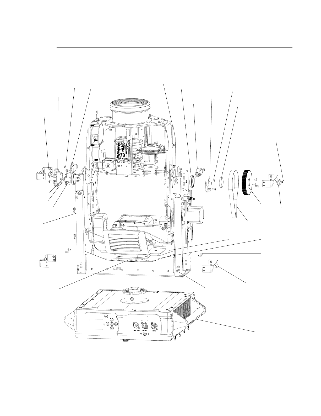
VARI❋LITE - VL4000 SPOT LUMINAIRE SERVICE MANUAL
VL4000 Generic Luminaire Assembly (continued)
10
16 (x6)
19
8
15 (x4)
22 (x2)
6 (x2)
4
18 (x3)*
2
24 (x2)
21 (x2)*
25 (x2)
11
17 (x5)*
13
14 (x16)*
3
23
1
5 (x4)
7
20 (x4)*
12
9
*APPLY LOCTITE 242 TO THREADS PRIOR TO INSTALLATION.
Figure 3-9: VL4000 Generic Luminaire Assembly
38 02.9704.0010 0
Page 57
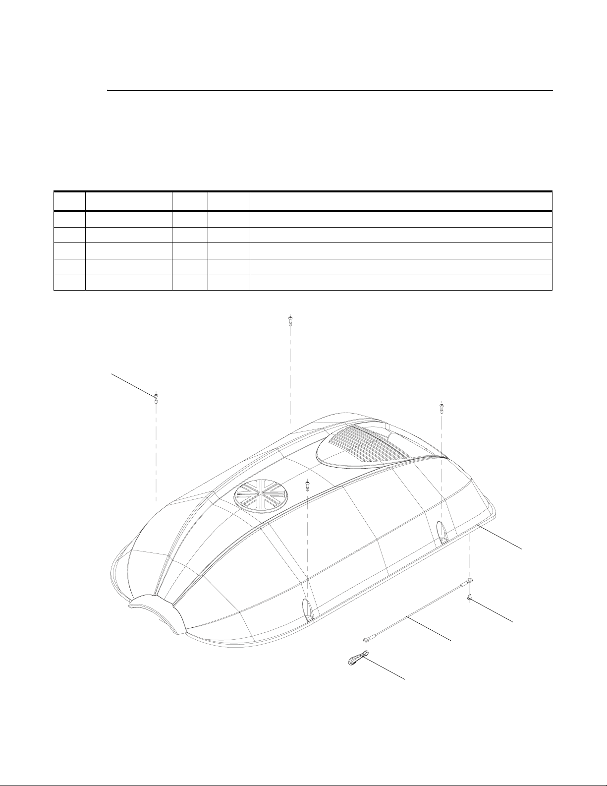
TOP ASSEMBLY : VL4000 HEAD COVER ASSEMBLY
VL4000 Head Cover Assembly
22.9704.0670 Rev. A
Refer to Figure 3-10
No. Item Qty. UM. Description
1 10.9704.0670 1 EA COVER, HEAD, TOP/BOTTOM
2 07.5049.0001 1 EA LANYARD, NYLON COATED, 8" LG
3 53.5655.0250 1 EA SCREW, #6 X 1/4" PPZ PLASTIC THD
4 53.6685.0500 4 EA SCREW, #6-32 X 1/2" PPB CAPTIVE
5 55.2011.0003 1 EA SNAP, SPRING 3/16" EYE DIA S
3
4 (x4)
1
3
2
5
Figure 3-10: VL4000 Head Cover Assembly
02.9704.0010 0 39
Page 58
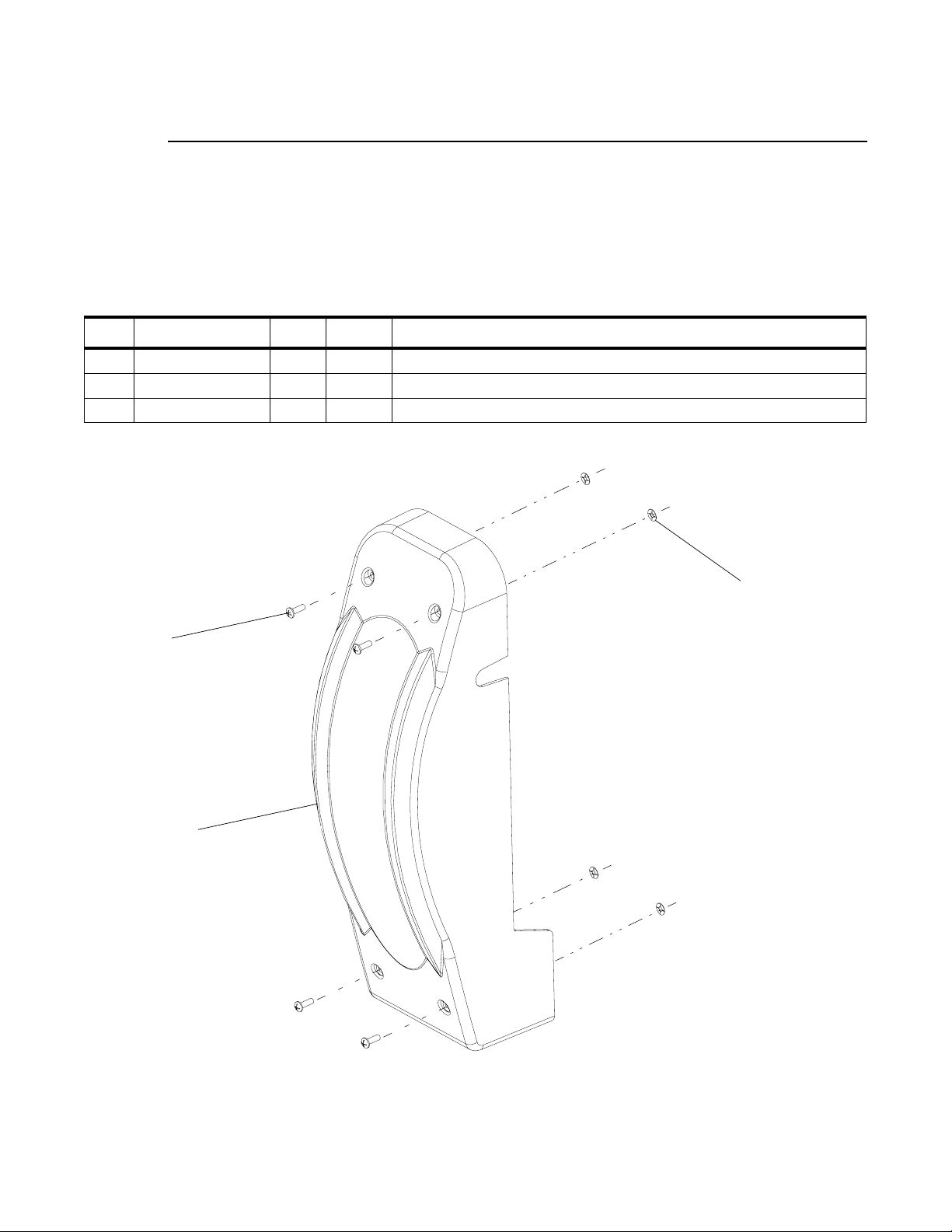
VARI❋LITE - VL4000 SPOT LUMINAIRE SERVICE MANUAL
VL4000 Yoke Arm Cover Assembly
22.9704.0732 Rev. A
Refer to Figure 3-11
No. Item Qty. UM. Description
1 53.2008.0008 4 EA NUT, #8 PUSH
2 53.6521.0001 4 EA SCREW, 8-32 X 1/2 PPB
3 10.9704.0732 1 EA COVER, YOKE ARM
2 (x4)
1 (x4)
3
Figure 3-11: VL4000 Yoke Arm Cover Assembly
40 02.9704.0010 0
Page 59
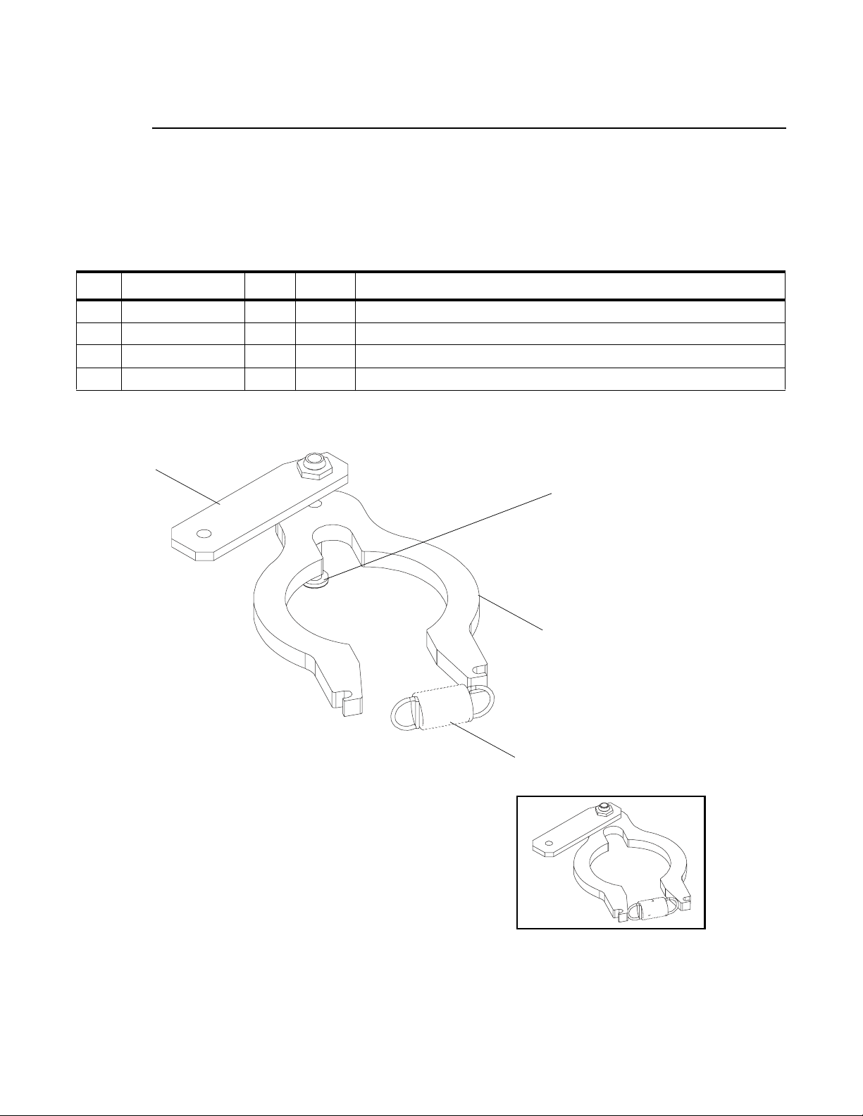
TOP ASSEMBLY : STABILIZER ASSEMBLY
Stabilizer Assembly
21.9704.1767 Rev. A
Refer to Figure 3-10
No. Item Qty. UM. Description
1 10.9704.1762 1 EA BRACKET, STABILIZER
2 10.9704.1757 1 EA STABILIZER, TILT, 1.600" SHAFT DIA
3 53.6610.0003 1 EA SCREW, 6-32 X 7/16" PPZ
4 55.6568.0075 1 EA SPRING, EXTN, 0.375" OD, 1.0" LG 0.041" WIRE DI A
1
3
3
2
4
Figure 3-12: Stabilizer Assembly
02.9704.0010 0 41
Page 60

VARI❋LITE - VL4000 SPOT LUMINAIRE SERVICE MANUAL
Notes
42 02.9704.0010 0
Page 61

HEAD ASSEMBLY : HEAD FRAME ASSEMBLY
Head Assembly
Head Frame Assembly
21.9704.0600 Rev. K
Refer to Figure 3-13
No. Item Qty. UM. Description
1 10.9704.0640 2 EA GUIDE, MODULE, HEAD
2 10.9704.0701 2 EA TILT TUBE
3 10.9704.1181 2 EA COUNTERWEIGHT, FRONT, SPOT
4 21.9704.0150 1 EA ASSY, ZOOM, VL4000 SPOT
5 21.9704.1615 1 EA ASSY, BACK END
6 22.9704.0605 1 EA ASSY, SIDE RAIL, RIGHT
7 22.9704.0608 1 EA ASSY, SIDE RAIL, LEFT
8 22.9704.1629 1 EA ASSY, VL4000 TILT MAGNET
9 23.9704.0003 2 EA FAN ASSY, VL4000 LAMP TIP AND BASE
10 23.9704.1002 2 EA FAN ASSY, VL4000 INLET AND GOBO
11 24.9704.2909 1 EA BOARD, 12V REGULATOR/DISTRO
12 53.5655.0251 4 EA SCREW, 6-20 X 1/4" PFZ THREAD FORMING
13 53.6528.0375 4 EA SCREW, #8-18 X 3/8, TYPE B, PFZ
14 53.6545.0003 4 EA SCREW, 8-32 X 3/8" PFZ
15 53.6552.0011 17 EA SCREW, 8-32 X 1/4" PFZ
16 53.6558.0009 1 EA SCREW, 6-32 X 3/8" LG PPZ SEMS
17 53.6575.0010 8 EA SCREW, 8-32 X 1/2" PPZ SEMS
18 53.6596.0001 4 EA SCREW, 4-40 X 5/16" PPZ
19 53.6613.0008 2 EA SCREW, 6-32 X 1/2" PPZ SEMS
20 53.6682.0022 4 EA SCREW, 8-32 X 3/8" PPZ SEMS
21 55.6576.0001 4 EA SCREW, #10-16 X 3/8" TYPE B PPZ
22 55.6775.0011 3 EA BUSHING, SNAP, 0.609ID, 0.75 MT HOLE, BLACK
3
02.9704.0010 0 43
Page 62
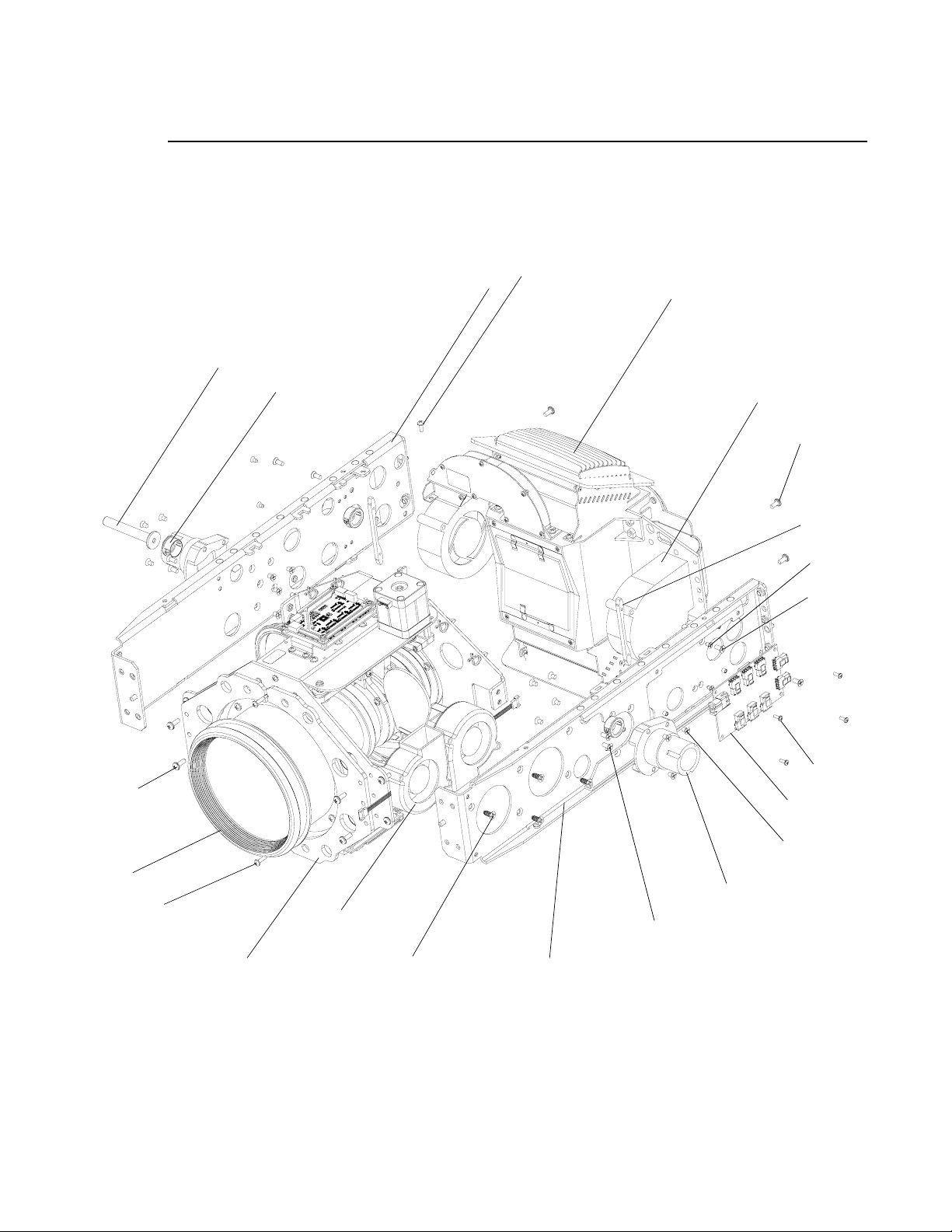
VARI❋LITE - VL4000 SPOT LUMINAIRE SERVICE MANUAL
Head Frame Assembly (continued)
7
8
16
5
17 (x8)
22 (x3)
9 (x2)
20 (x4)
1 (x2)
12 (x4)
13 (x4)
18 (x4)
11
15 (x17)
4
19 (x2)
3 (x2)
10 (x2)
21 (x4)
14 (x4)*
6
*APPLY LOCTITE 242 TO THREADS PRIOR TO INSTALLATION.
2 (x2)
Figure 3-13: Head Frame Assembly
44 02.9704.0010 0
Page 63

HEAD ASSEMBLY : VL4000 ZOOM SPOT ASSEMBLY
VL4000 Zoom Spot Assembly
21.9704.0150 Rev. K
Refer to Figure 3-14 and Figure 3-15
No. Item Qty. UM. Description
1 04.9704.0115 1 EA DIPSWITCH LABEL, OPTICS BOARD E
2 04.9704.0116 1 EA DIPSWITCH LABEL, OPTICS BOARD F
3 10.9704.0138 2 EA MOUNT, DRIVER BOARD
4 10.9704.0139 1 EA STOP, EOT, LENS G3
5 10.9704.0140 6 EA HALF LENS HOLDER
6 10.9704.0180 2 EA H EXTRUSION
7 10.9704.0181 1 EA MOUNT, LENS GROUP 4
8 10.9704.0182 1 EA REAR ASSY MOUNT SUPPORT
9 10.9704.0183 1 EA FIX MOUNT, LENS GROUP 2
10 10.9704.0186 1 EA MOUNT, LENS GROUP 1
11 10.9704.0187 1 EA MOUNT, LENS GROUP 3
12 10.9704.0188 1 EA CLAMP, BELT DRIVE
13 10.9704.0189 1 EA BELT HOLDER, LENS GROUP 3
14 12.9704.0113 2 EA RAIL AND CARRIAGE ASSY
15 21.9704.0134 1 EA ASSY, PRISM MOTOR
16 21.9704.0135 1 EA ASSY, FROST MOTOR
17 21.9704.0155 1 EA ASSY, LENS GROUP 3 MOTOR
18 22.9704.0121 1 EA GROUP 1 LENS TUBE ASSY
19 22.9704.0122 1 EA GROUP 2 LENS TUBE ASSY
20 22.9704.0123 1 EA GROUP 3 LENS TUBE ASSY
21 22.9704.0124 1 EA GROUP 4 LENS TUBE ASSY
22 24.9704.2901 2 EA PCB ASSY, 5-WAY MOTOR DRIVER
23 25.9687.0020 4 EA SWITCH, SLOTTED, OPTICAL
- 25.9704.2100 1 EA CABLE ASSY, VL4000 OPTICS, BULKHEAD CABLE 1 (NOT SHOWN)
- 25.9704.2101 1 EA CABLE ASSY, VL4000 OPTICS, BULKHEAD CABLE 2 (NOT SHOWN)
- 25.9704.0104 1 EA CABLE ASSY, VL4000 OPTICS, BULKHEAD CABLE 3 (NOT SHOWN)
- 25.9704.0105 1 EA CABLE ASSY, VL4000 OPTICS, BULKHEAD CABLE 4 (NOT SHOWN)
- 25.9704.0715 1 EA CABLE ASSY, VL4000 DATA, OPTICS-E TO OPTICS-F (NOT SHOWN)
24 44.9686.0164 1 EA MOTOR, SPLIT LENS
25 53.2200.0008 1 EA NUT, 8-32 KEPS SS
26 53.2202.0004 3 EA NUT, 4-40 HEX SS NYLON INSERT
3
02.9704.0010 0 45
Page 64

VARI❋LITE - VL4000 SPOT LUMINAIRE SERVICE MANUAL
No. Item Qty. UM. Description
27 53.6513.0019 4 EA SCREW, M3 X .5 X 5 MM PPB
28 53.6513.0032 4 EA SCREW, M3 X .5 X 10 MM LG PPZ SEMS
29 53.6523.0001 8 EA SCREW, 6-32 X 3/8" PPB
30 53.6537.0001 3 EA SCREW, 4-40 X 5/8" PPB
31 53.6558.0007 5 EA SCREW, 6-32 X 1/4" PPZ SEMS
32 53.6558.0009 21 EA SCREW, 6-32 X 3/8" PPZ SEMS
33 53.6575.0009 11 EA SCREW, 8-32 X 3/8" PPB SEMS
34 53.2002.0003 1 EA NUT, 6-32 HEX ZINC, NYLON INSERT
35 53.6682.0002 14 EA SCREW, 4-40 X 1/4" PPZ SEMS
36 53.6683.0015 12 EA SCREW, 6-32 X 3/16" PPZ SEMS
37 55.6636.0003 1 EA WASHER, 0.562" OD, 0.156" ID, 0.046" THK
38 55.6664.0002 2 EA STANDOFF, 1/4" HEX, 4-40 X 0.375" LG, MF, Z ST
39 10.9704.1151 1 EA SPACER, LINEAR ACTUATOR, G1
40 55.9704.0100 2 EA SHAFT, LINEAR ACTUATOR
41 10.9704.0693 2 EA CLAMP, CONN, 5 DRIVER BRD
42 53.6520.0001 6 EA SCREW, 4-40 X 3/8" PPZ
43 55.2203.0001 2 EA SCREW, 4-40 X 1/4" PPZ
44 55.6818.0002 4 EA CABLE TIE, KURLY-LOC
45 55.6775.0011 4 EA BUSHING, SNAP, 0.609 ID, 0.75 MT HOLE, BLACK
46 54.1261.0001 2 EA BUSHING, LOW DAMP THTMOPLS, 0.189 ID
47 55.3301.0004 4 EA WASHER, #4 FLAT SS
46 02.9704.0010 0
Page 65
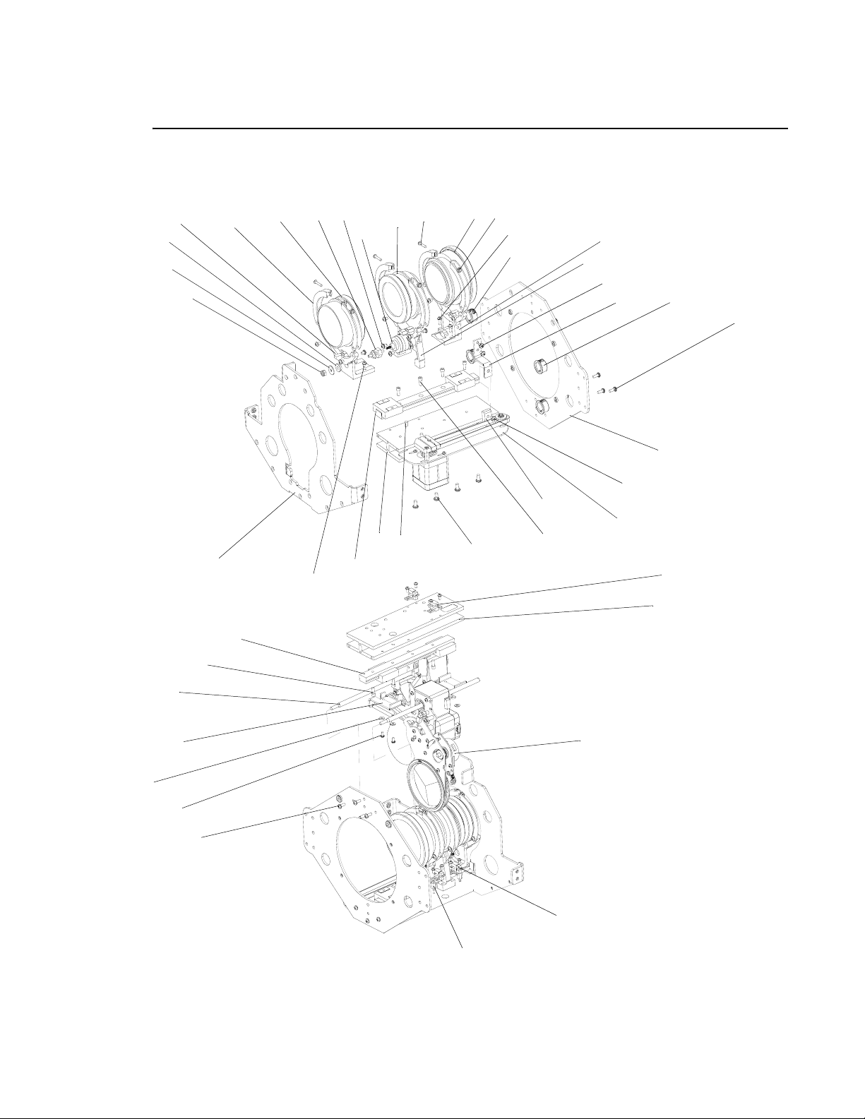
HEAD ASSEMBLY : VL4000 ZOOM SPOT ASSEMBLY
VL4000 Zoom Spot Assembly (continued)
26 (x3)
20
28 (x4)
36 (x12)
46 (x2)
37
10
34
5 (x6)
18
39**
31 (ref)
24
19
30 (x3)
9
11
31 (x5)
13
3
45 (x4)
32 (x7)
7
40 (x2)
47 (x4)
35 (x14)
29 (x4)*
16
32 (x8)
8
14***
27 (x4)*
14***
6
33 (ref)
33 (x6)
31 (ref)
12
17
29 (x4)*
23 (x4)
6
15
*APPLY LOCTITE 242 TO THREADS PRIOR TO
INSTALLATION.
**APPLY LOCTITE 272 TO ATTACH SPACER TO
LINEAR ACTUATOR SHAFT.
***RAIL SHOULD HANG OFF END OF H
EXTRUSION
38 (x2)*
23 (ref)
Figure 3-14: VL4000 Zoom Spot Assembly (Part 1)
02.9704.0010 0 47
Page 66
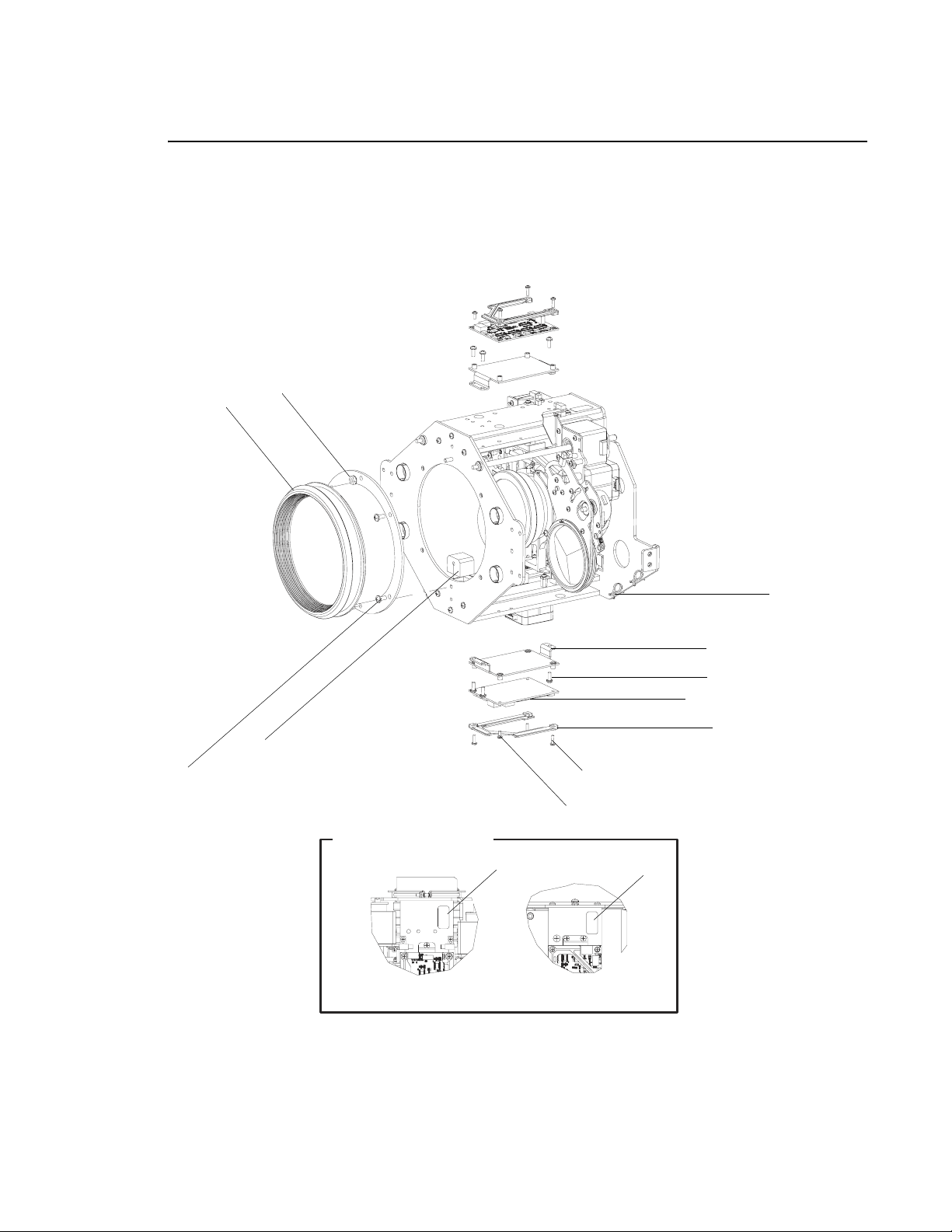
VARI❋LITE - VL4000 SPOT LUMINAIRE SERVICE MANUAL
VL4000 Zoom Spot Assembly (continued)
33 (x5)
21
25
44 (x4)
3 (x2)
32 (x6)
22 (x2)
41 (x2)
4
42 (x6)
43 (x2)
Label Placement
Lens Assy (Rear)
Top View
1
Lens Assy (Front)
Bottom View
2
Figure 3-15: VL4000 Zoom Spot Assembly (Part 2)
48 02.9704.0010 0
Page 67
HEAD ASSEMBLY : PRISM MOTOR ASSEMBLY
Prism Motor Assembly
21.9704.0134 Rev. F
Refer to Figure 3-16
No. Item Qty. UM. Description
1 10.9698.0335 1 EA DAMPER, MOTOR SHAFT, 5 MM
2 10.9704.0172 1 EA PRISM/FROST LIMIT STOP
3 10.9704.0194 1 EA MOUNT, PRISM ASSY
4 10.9704.0199 1 EA HOMING FLAG, FROST
5 21.9704.0115 1 EA ASSY, PRISM
6 25.9687.0020 1 EA SWITCH, SLOTTED OPTICAL
7 44.9698.0147 1 EA LINEAR MOTOR, SIZE 17
8 44.9698.1215 1 EA MOTOR, SIZE-17, ZOOM
9 53.6520.0002 1 EA SCREW, 4-40 X 7/16" PPZ
10 53.6520.0375 4 EA SCREW, 4-40 X 3/8" PPZ SEMS
11 53.6536.0001 1 EA SCREW, 4-40 X 1/2" PFZ
12 53.6559.0001 2 EA SCREW, 4-40 X 1/4" PFZ
13 53.6578.0002 2 EA SCREW, 6-32 X 3/16" SET CUP PT
14 53.6682.0002 2 EA SCREW, 4-40 X 1/4" PPZ SEMS
15 55.6568.0130 1 EA SPRING, EXTSN, 0.188OD 0.022WD 2.00 LG, MW
3
02.9704.0010 0 49
Page 68
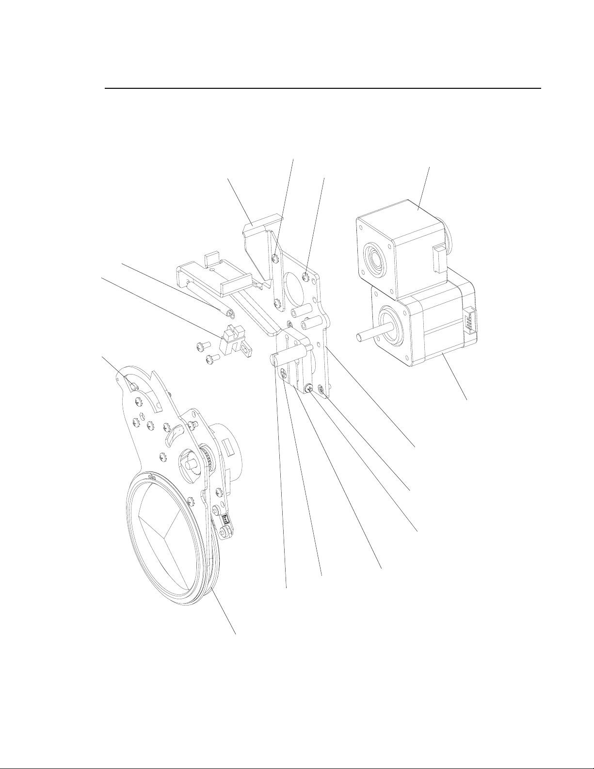
VARI❋LITE - VL4000 SPOT LUMINAIRE SERVICE MANUAL
Prism Motor Assembly (continued)
6
13 (x2)*
15
10 (x4)
4
14 (x2)
7
8
3
12*
9*
11
2
5
*APPLY LOCTITE 242 TO THREADS PRIOR TO INSTALLATION.
1
Figure 3-16: Prism Motor Assembly
50 02.9704.0010 0
Page 69
HEAD ASSEMBLY : PRISM ASSEMBLY
Prism Assembly
21.9704.0115 Rev. C
Refer to Figure 3-17
No. Item Qty. UM. Description
1 10.9698.0331 2 EA SPACER, TEFLON, PRISM
2 10.9698.0332 1 EA BEARING, BORE, TEFLON
3 10.9698.0334 1 EA RETAINING RING, PRISM
4 10.9698.1468 1 EA PULLEY, MOTOR, PRISM DRIVE
5 10.9704.0176 1 EA PRISM ARM SHEET METAL
6 10.9704.0192 1 EA MOUNT, PRISM MOTOR
7 10.9704.0193 1 EA HUB, PRISM ARM
8 17.9704.0904 1 EA PCB ASSY, WHEEL POSITION SENSOR
9 22.9704.0118 1 EA ASSY, PRISM ROTATOR W/MAGNET
10 44.9687.1218 1 EA MOTOR, SIZE 14, LO-PRFL, 0.9 DEG
11 53.6520.0375 3 EA SCREW, 4-40 X 3/8" PPZ SEMS
12 53.6578.0002 2 EA SCREW, 6-32 X 3/16" SET CUP PNT
13 53.6659.0002 2 EA SCREW, 2-56 X 1/4" PPZ
14 53.6682.0002 5 EA SCREW, 4-40 X1/4" PPZ SEMS
15 54.2057.0003 1 EA BELT, TIMING, MXL, 144 GRV, 0.125" WD, SIL/KVLR
16 55.6677.0050 2 EA WASHER, 0.27" OD, 0 .129" ID, 0.030" THK, TEFLON
3
02.9704.0010 0 51
Page 70
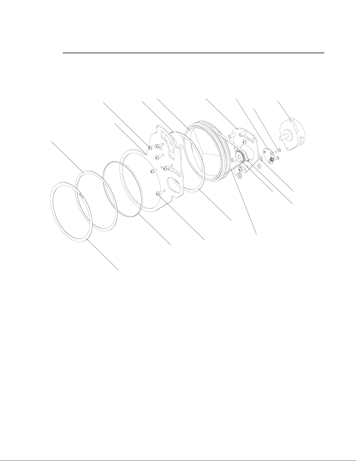
VARI❋LITE - VL4000 SPOT LUMINAIRE SERVICE MANUAL
Prism Assembly (continued)
9
14 (x5)
5
1
7
2
6
11 (x3)
8
13 (x2)
1
15
10
4
16 (x2)
12 (x2)*
3
*APPLY LOCTITE 242 TO THREADS PRIOR TO INSTALLATION.
Figure 3-17: Prism Assembly
52 02.9704.0010 0
Page 71
HEAD ASSEMBLY : FROST MOTOR ASSEMBLY
Frost Motor Assembly
21.9704.0135 Rev. H
Refer to Figure 3-18
No. Item Qty. UM. Description
1 10.9698.0335 1 EA DAMPER, MOTOR SHAFT, 5 MM
2 10.9704.0145 1 EA HOMING FLAG, FROST
3 10.9704.0172 1 EA PRISM/FROST LIMIT STOP
4 10.9704.0195 1 EA MOUNT, FROST FLAG
5 21.9704.0136 1 EA ASSY, FLAG, FROST
6 25.9687.0020 1 EA SWITCH, SLOTTED OPTICAL
7 44.9676.0117 1 EA MOTOR, GOBO ROTATE/INDEX
8 44.9698.0147 1 EA LINEAR MOTOR, SIZE 17
9 53.6520.0002 1 EA SCREW, 4-40 X 7/16" PPZ
10 53.6520.0375 4 EA SCREW, 4-40 X 3/8" PPZ SEMS
11 53.6536.0001 1 EA SCREW, 4-40 X 1/2" PFZ
12 53.6559.0001 2 EA SCREW, 4-40 X 1/4" PFZ
13 53.6578.0002 2 EA SCREW, 6-32 X 3/16" SET CUP PT
14 53.6596.0002 1 EA SCREW, 4-40 X 5/16" LG PPZ SEMS
15 55.6682.0002 2 EA SCREW, 4-40 X 1/4" PPZ SEMS
16 55.6568.0130 1 EA SPRING, EXTSN, 0.188OD 0.022WD 2.00 LG, MW
3
02.9704.0010 0 53
Page 72
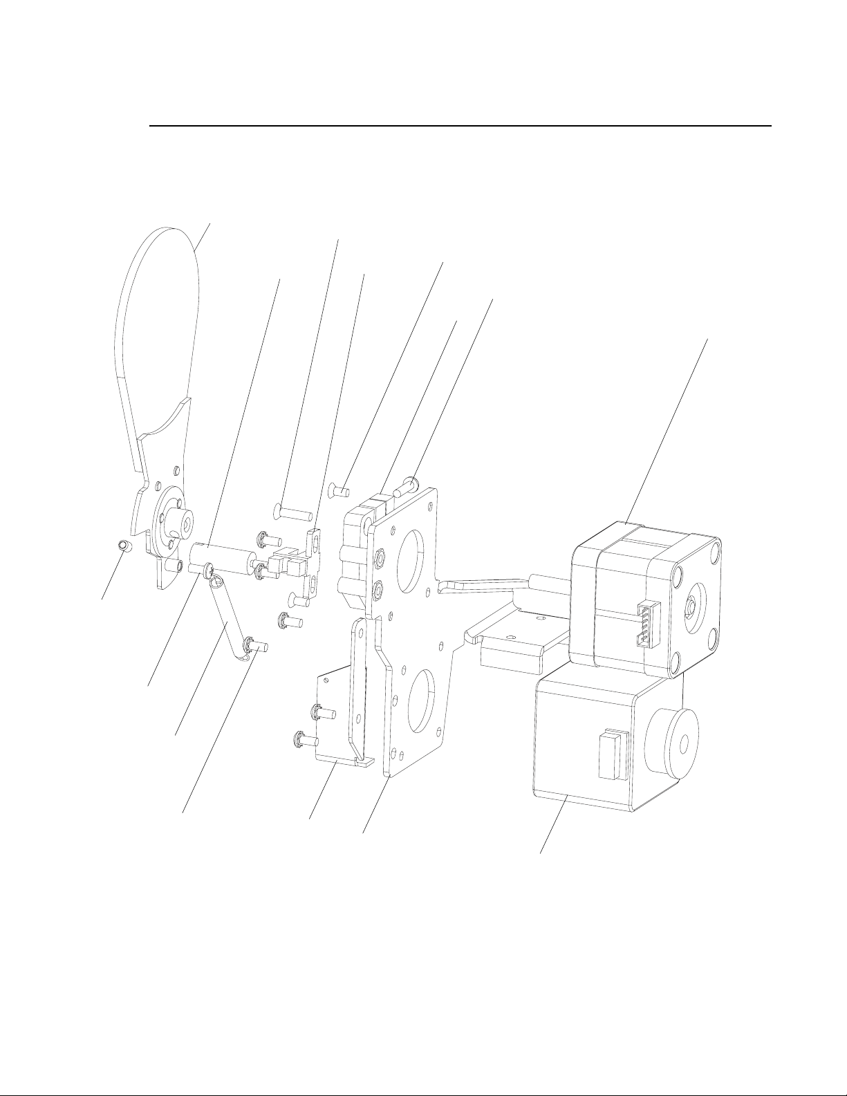
VARI❋LITE - VL4000 SPOT LUMINAIRE SERVICE MANUAL
Frost Motor Assembly (continued)
13 (x2)
5
3*
11*
6
12 (x2)*
9
1
7
14*, **
16
15 (x2)*
*APPLY LOCTITE 242 TO THREADS PRIOR TO INSTALLATION.
*DO NOT THREAD SCREW IN ALL THE WAY IN. LEAVE SPACE
FOR SPRING TO ROTATE FREELY.
2
4
8
Figure 3-18: Frost Motor Assembly
54 02.9704.0010 0
Page 73
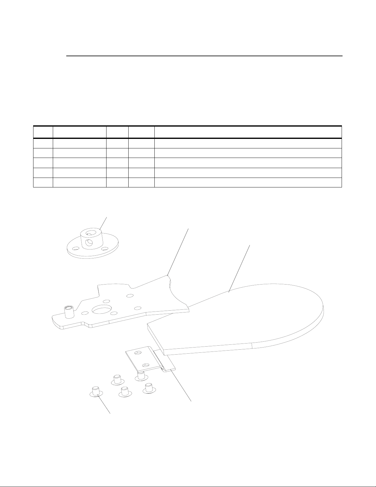
HEAD ASSEMBLY : FROST FLAG ASSEMBLY
Frost Flag Assembly
21.9704.0136 Rev. C
Refer to Figure 3-18
No. Item Qty. UM. Description
1 10.9687.0223 1 EA HUB, 5 MM SHAFT, 0.250" TALL
2 10.9704.0141 1 EA FROST FLAG SHEET METAL
3 10.9704.0142 1 EA FROST FLAG HOLDER CLIP
4 42.9704.1152 1 EA GLASS, FROST
5 53.6530.0011 5 EA RIVET, POP, 1/8" OD X 0.031-0.062 GR
3
1
5 (x5)
2 (See Notes)
4 (See Notes)
A
B
NOTES:
A. APPLY LOCTITE 498 TO ITEM 2 WHERE
NOTED. INSTALL ITEM 4. LET SET UNTIL DRY.
B. APPLY RTV 5083 TO ITEM 4 WHERE NOTED.
3
PRESS ITEM 3 ON. RIVET TO SECURE. CURE
UNDER UV.
Figure 3-19: Frost Flag Assembly
02.9704.0010 0 55
Page 74
VARI❋LITE - VL4000 SPOT LUMINAIRE SERVICE MANUAL
Lens Group 3 Motor Assembly
21.9704.0155 Rev. A
Refer to Figure 3-16
No. Item Qty. UM. Description
1 10.9663.1212 1 EA MOTOR PULLEY WITH FLANGES
2 10.9678.1131 1 EA FORWARD PULLEY SHAFT, BEARING
3 10.9698.0335 1 EA DAMPER, MOTOR SHAFT 5 MM
4 10.9704.0185 1 EA MOTOR PLATE, BELT DRIVE
5 44.9698.1215 1 EA MOTOR, SIZE-17, ZOOM
6 53.5560.0187 2 EA SCREW, SET 8-32 X 3/16" L
7 53.6520.0002 1 EA SCREW, 4-40 X 7/16" PPZ
8 53.6599.0001 1 EA SCREW, 4-40 X 3/8" PFZ
9 53.6682.0002 3 EA SCREW, 4-40 X 1/4" PPZ SEMS
10 54.1262.0001 2 EA BEARING, FLANGED, 0.1875" BORE
11 54.2053.0001 1 EA MXT T BELT PULLEY, 20 GRV, 0.25" WD
12 54.9704.0135 1 EA TIMING BELT, MXL, 155 TEETH, 0.1875" WD
13 55.2234.0001 1 EA E-RING, 0.188" SHAFT DIA, CAR SP
14 55.6664.0003 1 EA STANDOFF, 1/4" HEX, 4-40 X 0.593" LG, M-F, ZINC
56 02.9704.0010 0
Page 75
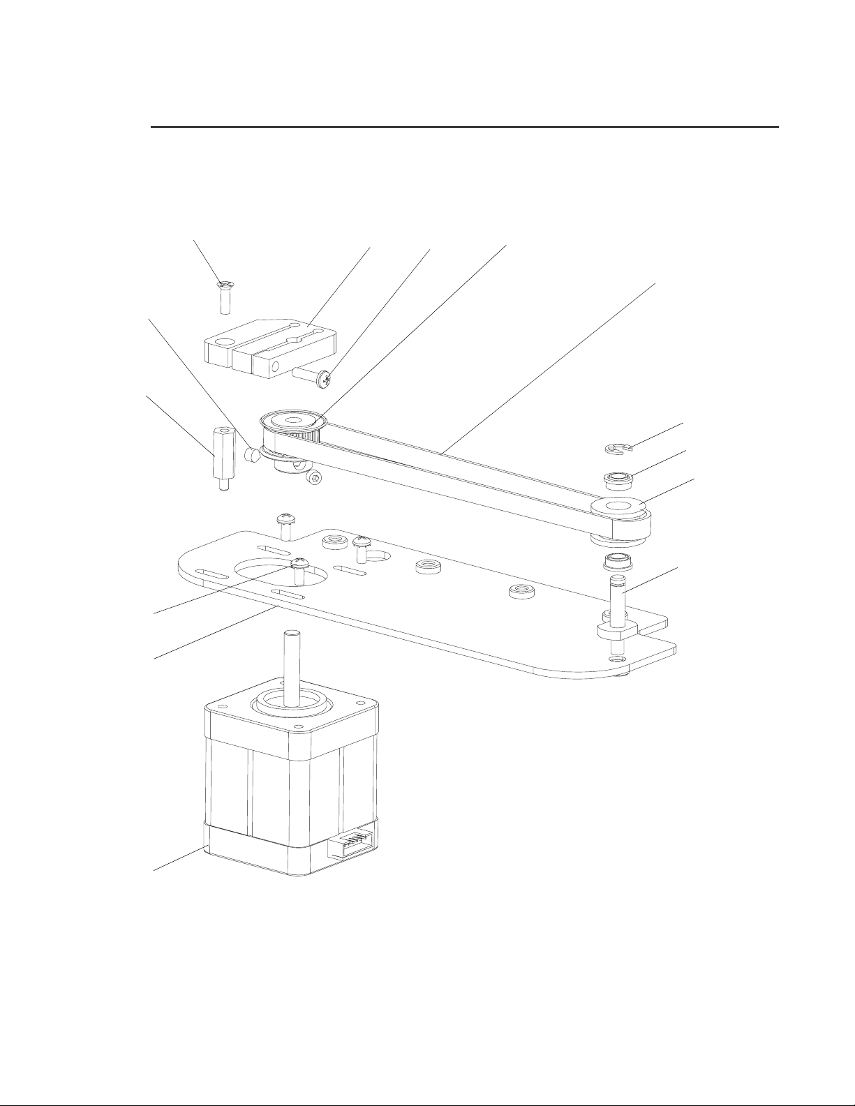
HEAD ASSEMBLY : LENS GROUP 3 MOTOR ASSEMBLY
Lens Group 3 Motor Assembly (continued)
3
6 (x2)*
14*
9 (x3)
8
3
7
1
12
13
10 (x2)
11
2*
4
5
*APPLY LOCTITE 242 TO THREADS PRIOR TO INSTALLATION.
Figure 3-20: Lens Group 3 Motor Assembly
02.9704.0010 0 57
Page 76
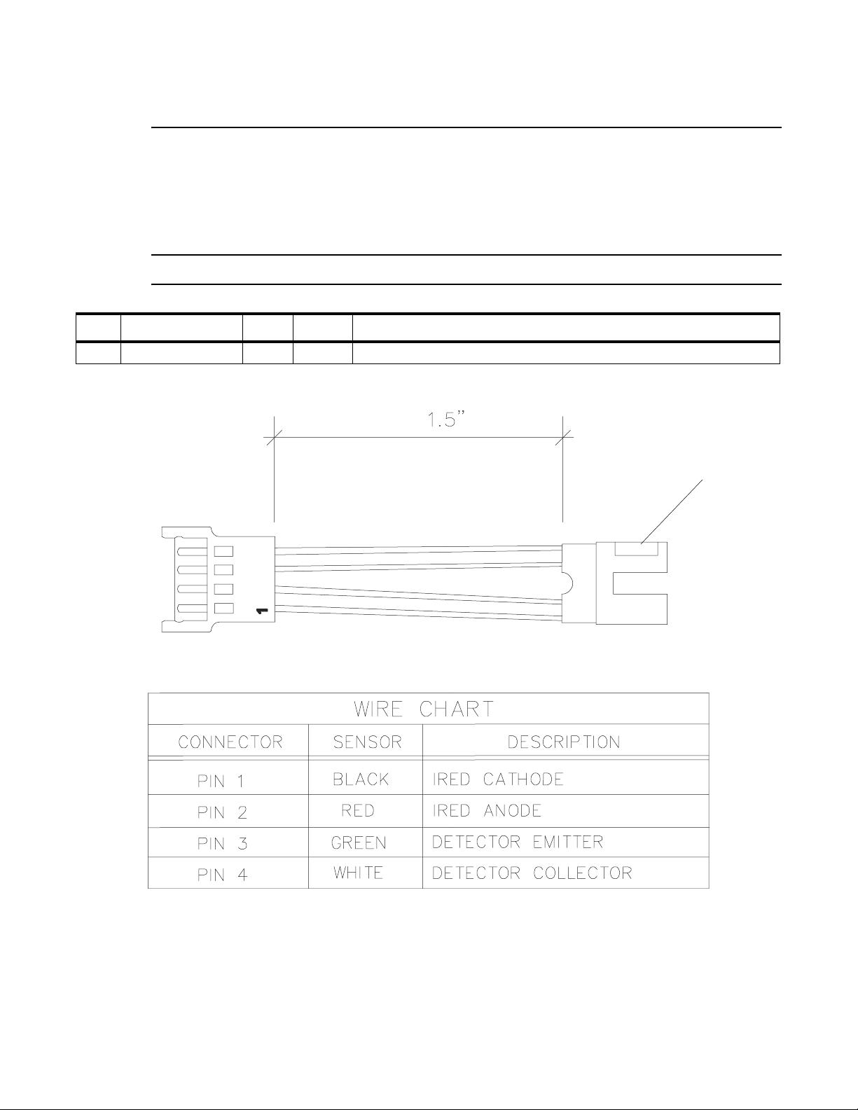
VARI❋LITE - VL4000 SPOT LUMINAIRE SERVICE MANUAL
Slotted Optical Switch
25.9687.0020 Rev. A
Refer to Figure 3-18
Note: This part is only available as an assembly. Shown for reference only.
No. Item Qty. UM. Description
1 25.9687.0020 1 EA SWITCH, SLOTTED OPTICAL
1
Figure 3-21: Slotted Optical Switch
58 02.9704.0010 0
Page 77

HEAD ASSEMBLY : BACK END ASSEMBLY
Back End Assembly
21.9704.1615 Rev. G
Refer to Figure 3-22
No. Item Qty. UM. Description
1 0-100071 3 EA SCREW, PHMS, PH, 10-32 X 1.75", S, BO
2 04.9704.0401 1 EA DIPSWITCH LABEL, COLOR BOARDS
3 10.9704.0613 1 EA MOUNT, HOT BOX
4 10.9704.0628 2 EA LIGHT SEAL, FIN ASSY
5 10.9704.1639 1 EA DIVERTER, LAMP TIP
6 10.9704.2614 1 EA PLATE, REAR
7 12.9704.0612 1 EA HOT BOX, MACHINED CASTING
8 12.9704.1629 1 EA EXTENSION, BACKCAP, MACHINED CASTING
9 21.9704.0619 1EAASSY, REFLECTOR
10 21.9704.0632 1 EA ASSY, LAMP COVER
11 22.9704.0630 1 EA ASSY, UV GLASS
12 22.9704.0633 1 EA ASSY, MOUNTED LAMP BASE DUCT
13 22.9704.0636 1 EA DUCT ASSY, LAMP TIP
14 22.9704.1618 1 EA ASSY, LAMP SOCKET PLATE
15 22.9704.1620 2 EA FIN ASSY, EXHAUST, TRI-BEND
- 25.9704.2701 1 EA CABLE ASSY, VL4000 LAMP SOCKET (NOT SHOWN)
16 53.6522.2500 1 EA SCREW, 6-32 X 1/4" HEX MACH, ZINC
17 53.6558.0003 1 EA SCREW, 6-32 X 3/8" PPZ PLASTIC THD
18 53.6558.0009 22 EA SCREW, 6-32 X 3/8" LG PPZ SEMS
19 53.6559.0001 4 EA SCREW, 4-40 X 1/4" PFZ
20 53.6596.0002 2 EA SCREW, 4-40 X 5/16" LG PPZ SEMS
21 53.6622.0001 2 EA SCREW, 8-32 X 1-1/4" PPZ
22 53.6682.0022 8 EA SCREW, 8-32 X 3/8" PPZ SEMS
23 55.2233.2006 2 EA DZUS RAPIER SNAP-IN RETAINER
24 55.6546.0004 3 EA WASHER, TEFLON, 0.201" ID X 0.433" OD
25 55.6568.1750 3 EA SPRING, CPRSN, 0.360" OD, 1.75" LG, 0.045" DIA SS
26 55.6636.0003 1 EA WASHER, 0.562" OD X 0.156" ID X 0.046" THK ZINC
27 71.8101.0050 1 EA LAMP SOCKET, BENDER AND WIRTH, PJGX50
3
02.9704.0010 0 59
Page 78
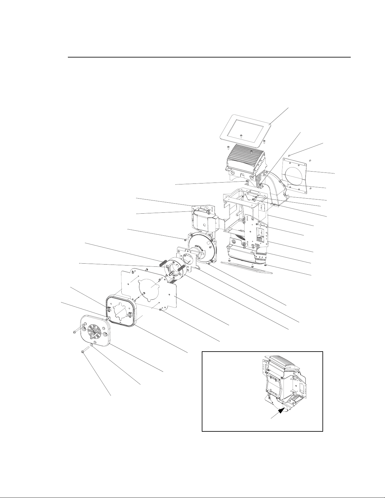
VARI❋LITE - VL4000 SPOT LUMINAIRE SERVICE MANUAL
Back End Assembly (continued)
4 (x2)
16
19 (x4)*
11
21 (x2)*
23 (x2)
26
25 (x3)
22 (x8)
18 (ref)
12
18 (ref)
2
13
5
20 (x2)
7
17
3
15 (x2)
18 (ref)
9
6
18 (x22)
8
14
27
10
24 (x3)
1 (x3)
Locate Item 2 as shown.
*APPLY LOCTITE 242 TO THREADS PRIOR TO INSTALLATION.
Figure 3-22: Back End Assembly
60 02.9704.0010 0
Page 79
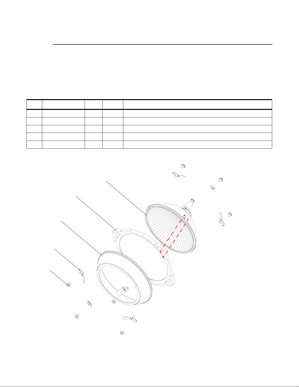
HEAD ASSEMBLY : REFLECTOR ASSEMBLY
Reflector Assembly
21.9704.0619 Rev. A
Refer to Figure 3-23
No. Item Qty. UM. Description
1 10.9704.0618 8 EA CLIP, REFLECTOR MOUNT
2 10.9704.0617 1 EA REFLECTOR MOUNT PLATE
3 42.9704.0150 1 EA REFLECTOR, PRIMARY
4 42.9704.0151 1 EA REFLECTOR, RETRO
5 53.6525.0188 8 EA SCREW, 6-32 X 3/16" LG PPZ
3
1 (x8)
5 (x8)
3
2
4
See Note
Note:
ALIGN BUMP ON REFLECTOR WITH
NOTCHED CORNER OF MOUNT PLATE.
BUMP FITS INSIDE SLOT IN MOUNTING
CLIP.
Figure 3-23: Reflector Assembly
02.9704.0010 0 61
Page 80
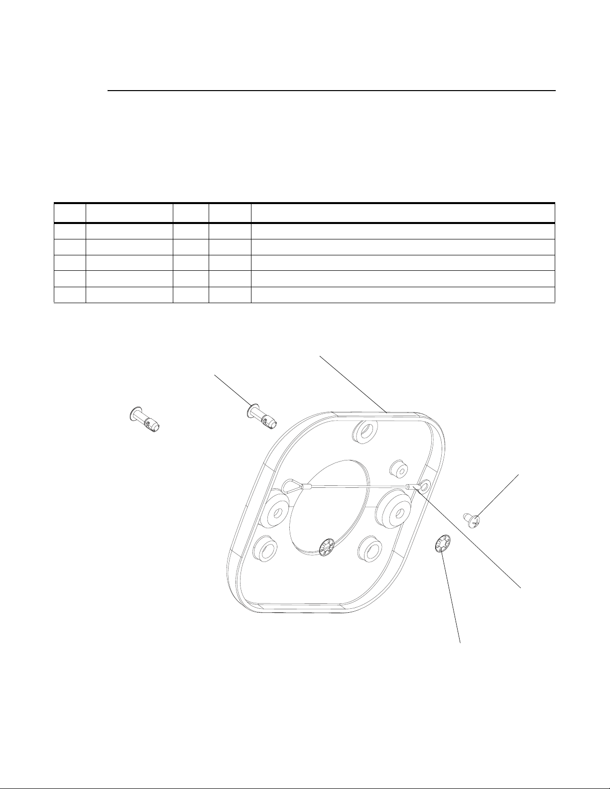
VARI❋LITE - VL4000 SPOT LUMINAIRE SERVICE MANUAL
Lamp Cover Assembly
21.9704.0632 Rev. B
Refer to Figure 3-23
No. Item Qty. UM. Description
1 10.9638.0233 1 EA TETHER, REMOVABLE COVER
2 10.9704.1630 1 EA HEAD COVER, LAMP SOCKET
3 53.5655.0250 1 EA SCREW, #6 X 1/4" LG PLASTIC THREADING
4 55.2233.2003 2 EA DZUS RAPIER, 1/4-TURN STUD RETAINER, 5 MM
5 55.2233.2005 2 EA DZUS RAPIER, 1/4-TURN STUD, 5 MM, 12 MM LG
5 (x2)
2
3
1
4 (x2)
Figure 3-24: Lamp Cover Assembly
62 02.9704.0010 0
Page 81

HEAD ASSEMBLY : SHUTTER/GOBO/ANIMATION MODULE ASSEMBLY
Shutter/Gobo/Animation Module Assembly
21.9704.0200 Rev. N
Refer to Figure 3-25, Figure 3-26, Figure 3-27, and Figure 3-28
No. Item Qty. UM. Description
1 - AR EA LOCTITE #242, REMOVABLE (BY OTHERS)
2 10.9698.0335 6 EA DAMPER, MOTOR SHAFT, 5 MM
3 10.9704.0223 4 EA DRIVE PULLEY, GOBO WHEEL
4 10.9704.0225 1 EA GOBO BULKHEAD BRACE
5 10.9704.0231 2 EA BLOCK SPACER, EDGE, GOBO BULKHEAD
6 10.9704.1233 2 EA PULLEY 16 GROOVE, ANIMATION ARM DRIVE
7 10.9704.0245 1 EA BULKHEAD, MIDDLE, GOBO MODULE
8 10.9704.0270 1 EA COOLING DUCT, GOBO BULKHEAD, TOP
9 10.9704.0271 1 EA COOLING DUCT, GOBO BULKHEAD, BOTTOM
10 10.9704.0272 1 EA COVER, COOLING DUCT, GOBO BULKHEAD
11 10.9704.0323 3 EA STANDOFF, ANIMATION MODULE, SHORT, #6-32
12 10.9704.0324 3 EA STANDOFF, ANIMATION MODULE, LONG, #6-32
13 21.9704.0211 1 EA ASSY, GOBO WHEEL 1
14 21.9704.0212 1 EA ASSY, GOBO WHEEL 2
15 21.9704.0230 1 EA ASSY, SENSOR, GOBO 1 INDEX
16 21.9704.0255 2EAASSY, MOTOR, EDGE
17 21.9704.0260 1 EA ASSY, SENSOR, GOBO 2 INDEX
18 21.9704.0281 1 EA ASSY, BRACKET, LEFT, GOBO BULKHEAD
19 21.9704.0282 1 EA ASSY, BRACKET, RIGHT, GOBO BULKHEAD
20 21.9704.1351 1 EA ASSY, ANIMATION WHEEL 1
21 21.9704.0352 1 EA ASSY, ANIMATION WHEEL 2
22 21.9704.1505 1 EA ASSY, SHUTTER BULKHEAD, WITH ROTATION
23 22.9704.0261 1 EA SHAFT ASSY, GOBO WHEEL 1
24 22.9704.0264 1 EA SHAFT ASSY, GOBO WHEEL 2
25 17.9704.0906 2 EA PCB ASSY, ANIMATION WHEEL INDEX
26 23.9704.0005 1 EA FAN ASSY, VL4000 INLET AND GOBO
- 25.9704.0200 1 EA CABLE ASSY, VL4000 GOBO BULKHEAD, CABLE 1
- 25.9704.0201 1 EA CABLE ASSY, VL4000 GOBO BULKHEAD, CABLE 2
- 25.9704.0202 1 EA CABLE ASSY, VL4000 GOBO BULKHEAD, CABLE 3
- 25.9704.0711 3 EA CABLE ASSY, VL4000 DATA NETWORK EXTENSION
27 44.9704.0209 2 EA MOTOR, SIZE 15, 5 X 17 MM SHAFT
3
02.9704.0010 0 63
Page 82

VARI❋LITE - VL4000 SPOT LUMINAIRE SERVICE MANUAL
No. Item Qty. UM. Description
28 44.9704.0217 4 EA MOTOR, SIZE 17, 24 MM SHAFT, SHORT STACK
29 53.6513.0003 6 EA SCREW, M3 X .5 X 4 MM LG, PPB, METRIC
30 53.6513.0008 6 EA SCREW, M3 X .5 X 5 MM LG, PPB, METRIC
31 53.6513.0034 2 EA SCREW, M3 X .5 X 10 MM LG, PFZ, METRIC
32 53.6513.0054 3 EA SCREW, M3 X .5 X 4 MM LG, PFZ, METRIC
33 53.6575.0009 6 EA SCREW, 8-32 X 3/8" PPZ SEMS
34 53.6558.0009 24 EA SCREW, 6-32 X 3/8" PPZ SEMS
35 53.6559.0001 9 EA SCREW, 4-40 X 1/4" PFZ
36 53.6578.0002 12 EA SCREW, 6-32 X 3/16" SET CUP PNT
37 53.6596.0002 6 EA SCREW, 4-40 X 5/16" PPZ SEMS
38 53.6601.0004 1 EA SCREW, 4-40 X 1/8" PFZ UNDERCUT
39 53.6604.0002 5 EA SCREW, 4-20 X 1/4" THREAD FORMING FOR PLASTICS
40 53.6604.0005 4 EA SCREW, 4-40 X 1/4" PFZ SHEET METAL
41 53.6609.0001 6 EA SCREW, 6-32 X 3/8" PFZ
42 53.9704.0004 2 EA SCREW, 10-32 X 3/8" HI-LO PPZ THD FORMING
43 54.9698.0002 2 EA BELT, TIMING, MXL, 150 GRV, 0.125" WD, URETH/KEV
44 54.9704.0290 2 EA BELT, TIMING, MXL, 155 GRV, 0.125" WD, URETH/KEV
45 54.9704.0296 2 EA BEARING, SLEEVE, FLNG, 0.314" ID, 0.439" OD, 1.00" LG, LUB BRNZ
46 54.9704.1390 2 EA BELT, TIMING, MXL, 102 GRV, 0.125" WD, URETH/KEV
47 55.2178.0001 2 EA CABLE ANCHOR POINT, #8 SCREW
48 55.2203.0001 6 EA SCREW, 4-40 X 1/4" PPZ
49 55.9704.0002 4 EA STANDOFF, 1/4" HEX, 6-32. 1.109" LG, FF, ALUM
50 10.9704.0249 1 EA SPACER, MOTOR SIZE 15
51 53.6513.0023 1 EA SCREW, M3 X 8 MM LG PFZ METRIC
52 53.6513.0024 2 EA SCREW, M3 X 8 MM LG PPZ METRIC
53 55.6503.0004 6 EA WASHER, FLAT, #8, ZINC
54 54.1261.0001 6 EA BUSHING, LOW DAMP THROMPLS, 0.189" ID
55 04.9704.0203 1 EA DIPSWITCH LABEL, GOBO BOARD C
56 04.9704.0204 1 EA DIPSWITCH LABEL, GOBO BOARD D
57 04.9704.1501 1 EA DIPSWITCH LABEL, SHUTTER BOARD
58 10.9704.0290 2 EA CLAMP, CONNECTOR, SENSOR BOARD
59 53.6659.0003 4 EA SCREW, 2-56 X 3/8" PPZ
60 53.6682.0002 1 EA SCREW, 4-40 X 1/4" PPZ SEMS
64 02.9704.0010 0
Page 83
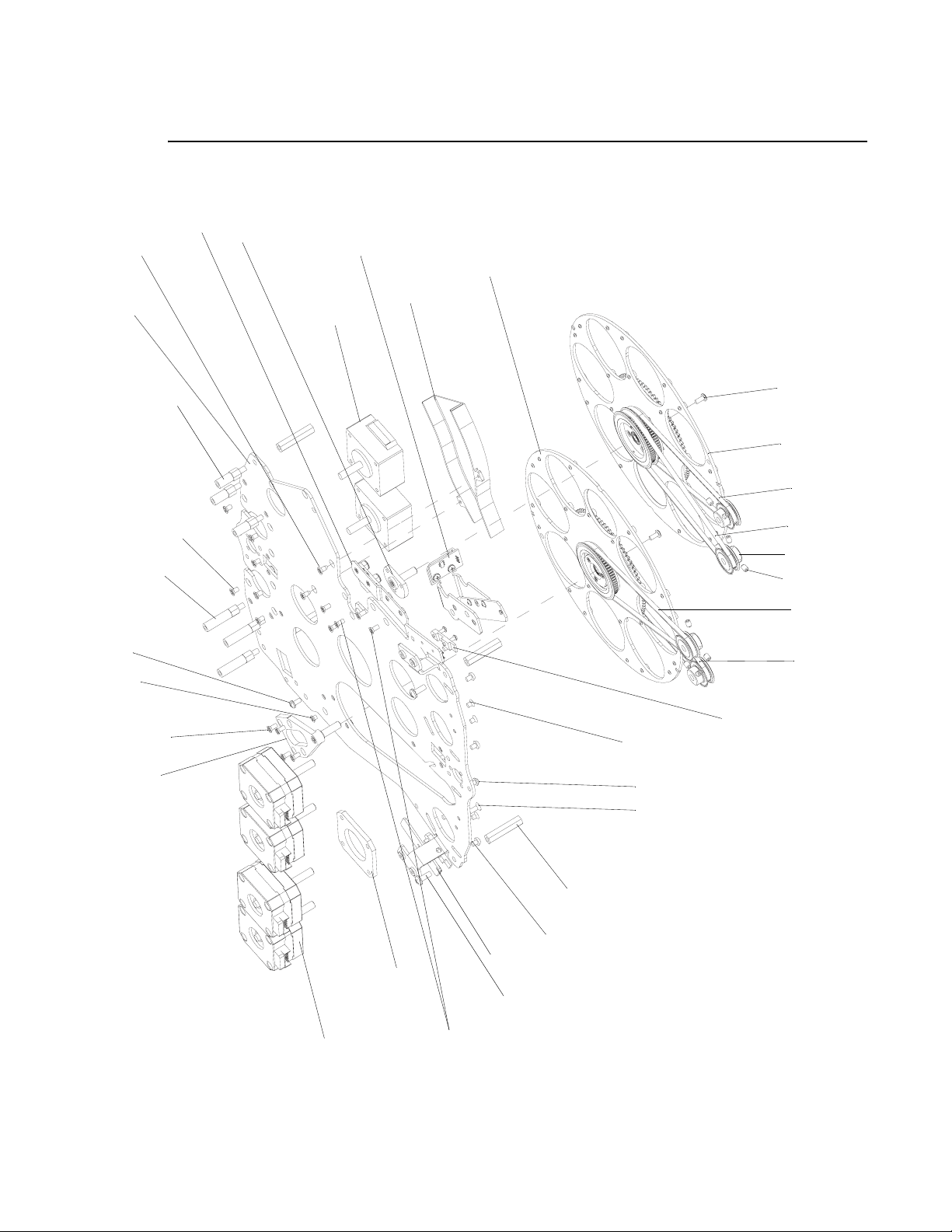
40 (x2)
7
HEAD ASSEMBLY : SHUTTER/GOBO/ANIMATION MODULE ASSEMBLY
3
Shutter/Gobo/Animation Module Assembly (continued)
17
24
15
13
9
27 (x2)
11 (x3)
30 (x6)*
12 (x3)
60
38*
35 (x9)*
23
48 (x6)*
14
43 (x2)
44 (x2)
3 (x4)
36 (x8)*
44 (ref)
43 (ref)
58 (x2), 59 (x4)
32 (x3)*
52 (x2)*
51*
49 (x4)
29 (x6)
25 (x2)
50
34 (x2)
28 (x4)
35 (ref)*
*APPLY LOCTITE 242 TO THREADS PRIOR TO INSTALLATION.
Figure 3-25: Shutter/Gobo/Animation Module Assembly (Part 1)
02.9704.0010 0 65
Page 84
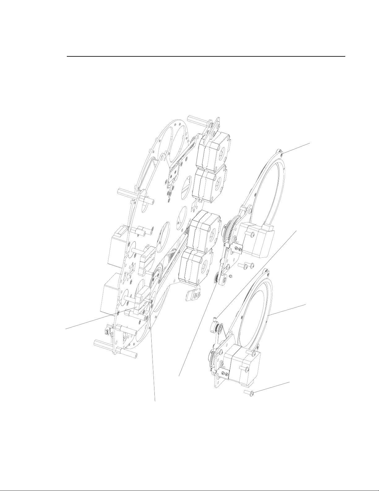
VARI❋LITE - VL4000 SPOT LUMINAIRE SERVICE MANUAL
Shutter/Gobo/Animation Module Assembly (continued)
21
2 (x2)
31 (x2)
6, 46 (x2)
3, 36 (x4)*
20
34 (x6)
*APPLY LOCTITE 242 TO THREADS PRIOR TO INSTALLATION.
Figure 3-26: Shutter/Gobo/Animation Module Assembly (Part 2)
66 02.9704.0010 0
Page 85
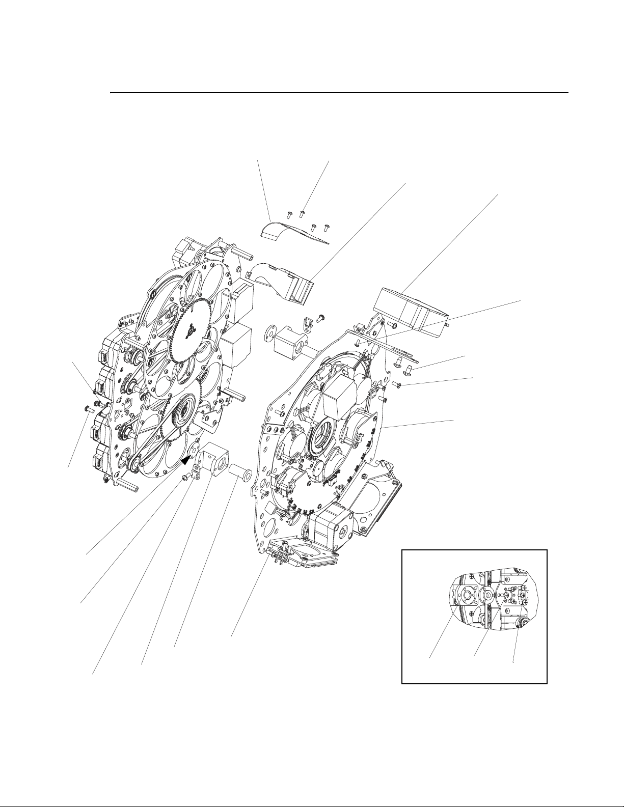
HEAD ASSEMBLY : SHUTTER/GOBO/ANIMATION MODULE ASSEMBLY
3
Shutter/Gobo/Animation Module Assembly (continued)
37 (x6)
10
39 (x5)
8
26
39 (ref)
42 (x2)
41 (x6)*
22
34 (ref)
See Detail
34 (ref)
34 (x12)
45 (x2)
5 (x2)
47 (x2)
*APPLY LOCTITE 242 TO THREADS PRIOR TO INSTALLATION.
Detail
5
34
37
Figure 3-27: Shutter/Gobo/Animation Module Assembly (Part 3)
02.9704.0010 0 67
Page 86
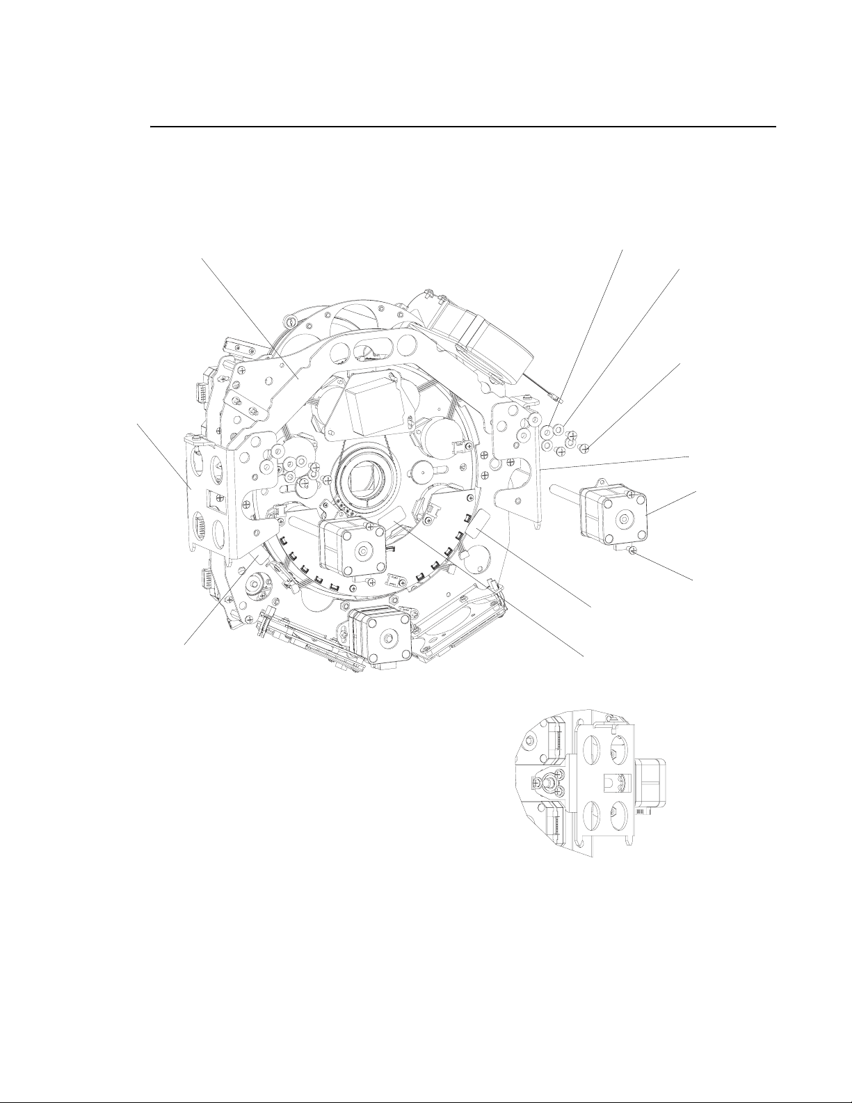
VARI❋LITE - VL4000 SPOT LUMINAIRE SERVICE MANUAL
Shutter/Gobo/Animation Module Assembly (continued)
19
4
54 (x6)
53 (x6)
33 (x6)*
18
16 (x2)
34 (x4)
56
55
57
*APPLY LOCTITE 242 TO THREADS PRIOR TO INSTALLATION.
Figure 3-28: Shutter/Gobo/Animation Module Assembly (Part 4)
68 02.9704.0010 0
Page 87
HEAD ASSEMBLY : GOBO WHEEL 1 ASSEMBLY
Gobo Wheel 1 Assembly
21.9704.0211 Rev. D
Refer to Figure 3-29
No. Item Qty. UM. Description
1 10.9704.0219 1 EA HUB, GOBO WHEEL
2 10.9704.0228 1 EA PULLEY, DRIVEN, GOBO WHEEL 1 INDEX
3 10.9704.0229 1 EA CAP, HUB, GOBO WHEEL 1
4 10.9704.0236 1 EA DRIVEN PULLEY, GOBO ROTATE
5 22.9704.0220 1 EA PLATE ASSY, ROTATING GOBO WHEEL
6 22.9704.0222 1 EA SUN GEAR, GOBO ROTATE WITH MAGNET
7 53.6659.0015 3 EA SCREW, 2-56 X 1/4" PFB
8 53.6659.0023 3 EA SCREW, 2-56 X 3/16" PFZ
9 53.6659.0027 4 EA SCREW, 2-56 X 5/16" PFZ
10 54.1259.0014 1 EA BEARING, TORQUE TUBE, 1.313 OD
11 54.9687.1253 3 EA BEARING, NPB, MR105ZZK13
12 55.2256.0001 1 EA MAGNET, 2:17 SMCO 2MM X 2MM X3MM
13 - AR EA LOCTITE #242, REMOVABLE (BY OTHERS)
14 10.9678.0250 1 EA MAGNET TAPE (NOT SHOWN)
3
Note: For included gobos, refer to “Included Items Kit, VL4000 Spot” on page 33.
02.9704.0010 0 69
Page 88
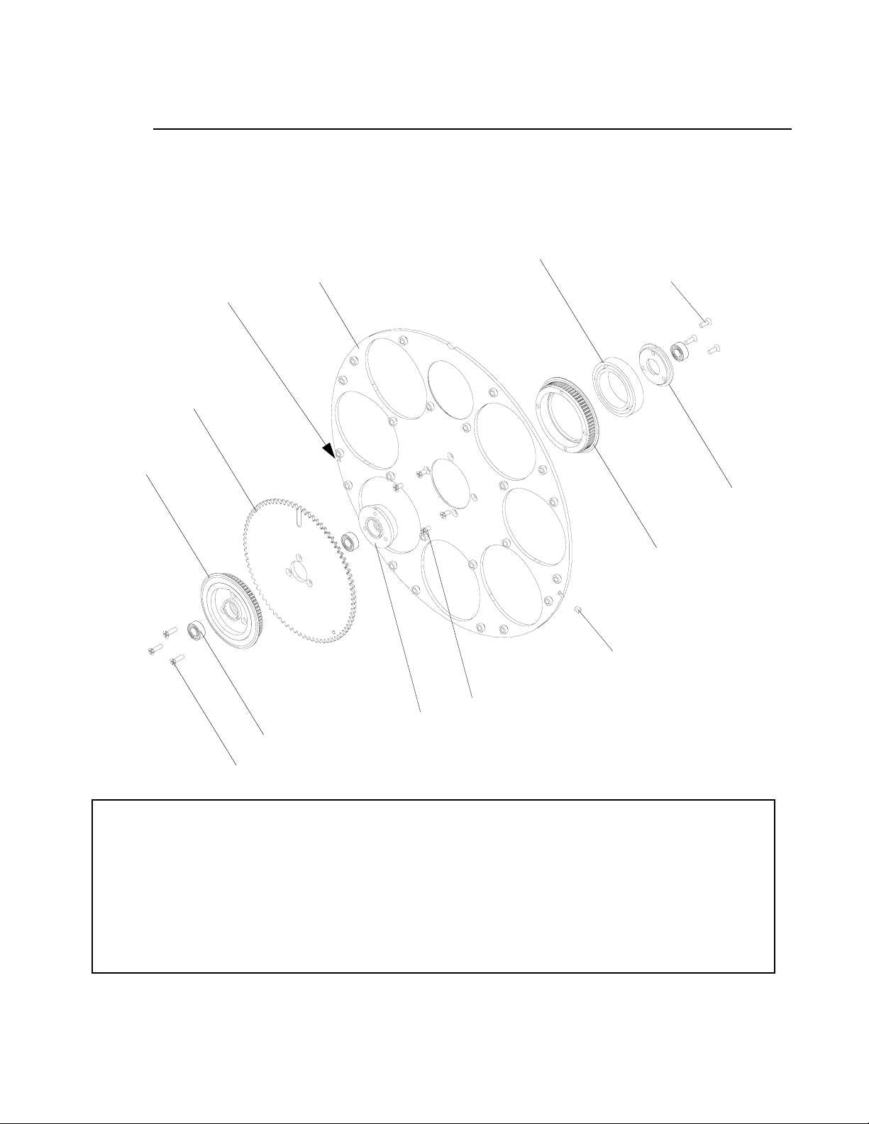
VARI❋LITE - VL4000 SPOT LUMINAIRE SERVICE MANUAL
Gobo Wheel 1 Assembly (continued)
5
Note, this slot is
not used.
6
2
10
7 (x3)*
3
4
12
9 (x4)*
1
11 (x3)
8 (x3)*
Notes:
*APPLY ONE DROP OF LOCTITE (ITEM 13) TO SCREW THREADS DURING INSTALLATION.
CLEAN AREA AROUND MAGNET SLOT IN WHEEL THOROUGHLY WITH SOLVENT. INSTALL MAGNET (ITEM 12) INTO SLOT, SOUTH POLE
FACING OUT, USING TAPE (ITEM 14). APPLY TAPE CENTE RE D ON MAGNET WITH LONG SIDE FOLDED EQUALLY OVER WHEEL EDGE. PRESS
TAPE FIRMLY IN PLACE TO PROMOTE ADHESION BY RUBBI NG WITH A BLUNT TOOL.
WHEN INSTALLING GOBO/GAG CARRIER, TIME ASSEMBL Y BY ALIGNING TIMING MARK ON SUN GEAR (ITEM 6) WITH HOLES ON PLANET
GEAR. ROTATE SUN GEAR SO WHITE MARK IS VISIBLE, THEN INSTALL CARRIER SO TWO TEETH WITH HOLES MESH WITH WHITE TOOTH.
REPEAT FOR ALL CARRIERS.
VERIFY THAT ASSEMBLY SPINS FREELY BY HOLDING SUN GEAR (ITEM 6) AND SPINNING THE PLATE/PLANETS AROUND WITH A FINGER IN
THE OPEN HOLE OF THE PLATE (ITEM 5). THERE SHOULD BE NO DRAG IN THE ASSEMBLY.
INSTALL PULLEY ( ITEM 2) AND GEAR (ITEM 6) TO ASSY LAST WHILE ALL THREE BEARINGS (ITEM 11) ARE ALIGNED ON AN AXLE SHAFT
BEFORE TIGHTENING THREE SCREWS TO ENSURE ALIGNMENT.
Figure 3-29: Gobo Wheel 1 Assembly
70 02.9704.0010 0
Page 89
HEAD ASSEMBLY : GOBO WHEEL 2 ASSEMBLY
Gobo Wheel 2 Assembly
21.9704.0212 Rev. E
Refer to Figure 3-30
No. Item Qty. UM. Description
1 10.9704.0219 1 EA HUB, GOBO WHEEL
2 10.9704.0236 1 EA DRIVEN PULLEY, GOBO ROTATE
3 10.9704.1216 1 EA SUN GEAR, GOBO ROTATE
4 22.9704.0207 1 EA DRIVEN PULLEY WITH MAGNET, GOBO WHEEL 2 INDEX
5 22.9704.0220 1 EA PLATE ASSY, ROTATING GOBO WHEEL
6 53.6659.0023 3 EA SCREW, 2-56 X 3/16" PFZ
7 53.6659.0027 7 EA SCREW, 2-56 X 5/16" PFZ
8 54.1259.0014 1 EA BEARING, TORQUE TUBE, 1.313 OD
9 54.9687.1253 3 EA BEARING, NPB, MR105ZZK13
10 55.2256.0001 1 EA MAGNET, 2:17 SMCO 2MM X 2MM X3MM
11 - AR EA LOCTITE #242, REMOVABLE (NOT SHOWN - BY OTHERS)
12 10.9678.0250 1 EA MAGNET TAPE (NOT SHOWN)
3
Note: For included gobos, refer to “Included Items Kit, VL4000 Spot” on page 33.
02.9704.0010 0 71
Page 90
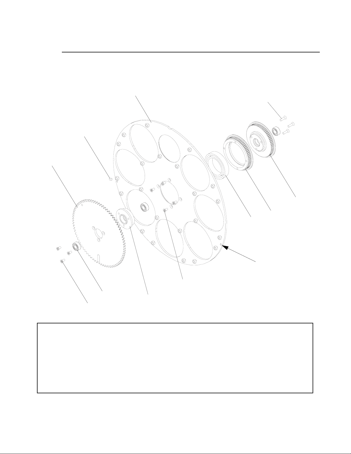
VARI❋LITE - VL4000 SPOT LUMINAIRE SERVICE MANUAL
Gobo Wheel 2 Assembly (continued)
5
6 (x3)*
10**
3
4
2
8
Note, this slot is
not used.
7 (x4)*
9 (x3)
1
7 (x3)*
Notes:
*APPLY ONE DROP OF LOCTITE (ITEM 13) TO SCREW THREADS DURING INSTALLATION.
**CLEAN AREA AROUND MAGNET SLOT IN WHEEL THOROUGHLY WITH SOLVENT. INSTALL MAGNET (ITEM 10) INTO SLOT, SOUTH POLE
FACING OUT, USING TAPE (ITEM 12). APPLY TAPE CENTE RE D ON MAGNET WITH LONG SIDE FOLDED EQUALLY OVER WHEEL EDGE. PRESS
TAPE FIRMLY IN PLACE TO PROMOTE ADHESION BY RUBBI NG WITH A BLUNT TOOL.
WHEN INSTALLING GOBO/GAG CARRIER, TIME ASSEMBL Y BY ALIGNING TIMING MARK ON SUN GEAR (ITEM 1) WITH HOLES ON PLANET
GEAR. ROTATE SUN GEAR SO WHITE MARK IS VISIBLE, THEN INSTALL CARRIER SO TWO TEETH WITH HOLES MESH WITH WHITE TOOTH.
REPEAT FOR ALL CARRIERS.
VERIFY THAT ASSEMBLY SPINS FREELY BY HOLDING SUN GEAR (ITEM 1) AND SPINNING THE PLATE/PLANETS AROUND WITH A FINGER IN
THE OPEN HOLE OF THE PLATE (ITEM 5). THERE SHOULD BE NO DRAG IN THE ASSEMBLY.
INSTALL PULLEY (ITEM 3) TO ASSY LAST WHILE ALL THREE BEARINGS (ITEM 9) ARE ALIGNED ON AN AXLE SHAFT BEFORE TIGHTENING
THREE SCREWS TO ENSURE ALIGNMENT.
Figure 3-30: Gobo Wheel 2 Assembly
72 02.9704.0010 0
Page 91
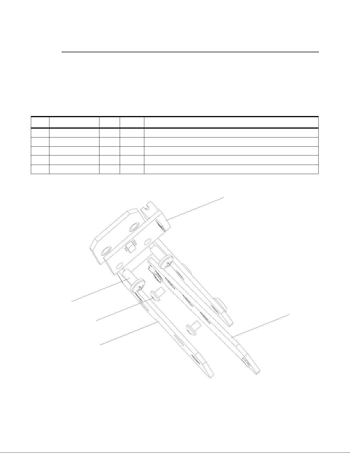
HEAD ASSEMBLY : GOBO 1 SENSOR INDEX ASSEMBLY
Gobo 1 Sensor Index Assembly
21.9704.0230 Rev. B
Refer to Figure 3-31
No. Item Qty. UM. Description
1 10.9704.0232 1 EA GOBO WHEEL 1 SENSOR BRACKET
2 17.9704.0905 1 EA PCB ASSY, GOBO 1 INDEX SENSOR
3 24.9678.3240 1 EA BRD ASSY, GOBO POSITION
4 53.6659.0012 2 EA SCREW, 2-56 X 1/8" PPZ
5 55.2203.0001 2 EA SCREW, 4-40 X 1/4" PPZ
3
5 (x2)
3
2
4 (x2)
1
Figure 3-31: Gobo 1 Sensor Index Assembly
02.9704.0010 0 73
Page 92
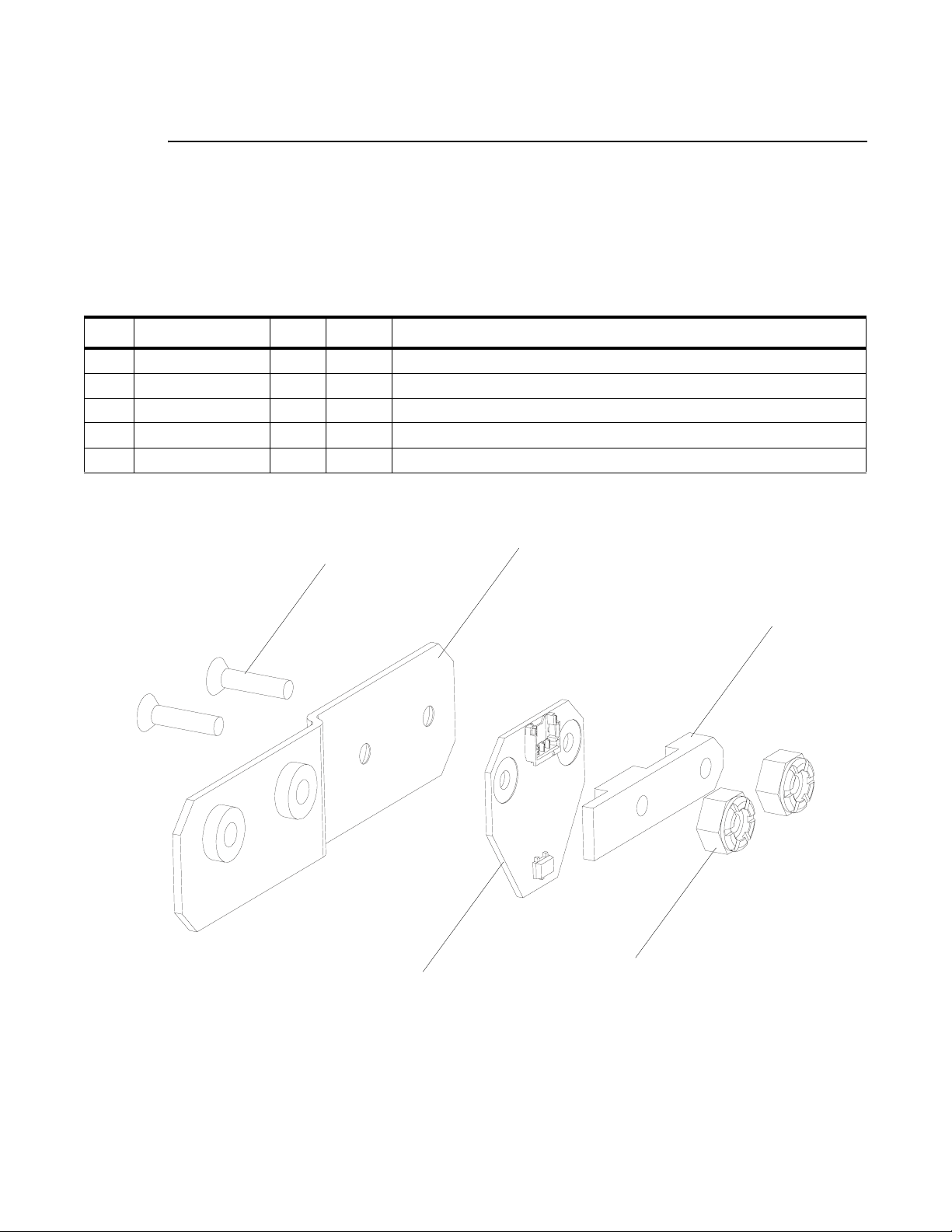
VARI❋LITE - VL4000 SPOT LUMINAIRE SERVICE MANUAL
Gobo 2 Sensor Index Assembly
21.9704.0260 Rev. B
Refer to Figure 3-32
No. Item Qty. UM. Description
1 10.9704.0290 1 EA CLAMP, CONNECTOR, SENSOR BOARD
2 10.9704.0253 1 EA MOUNT, SENSOR BOARD, GOBO INDEX
3 53.2009.0006 2 EA NUT, 2-56 HEX NYLON LOCK SS
4 17.9704.0904 1 EA PCB ASSY, WHEEL POSITION SENSOR
5 53.6659.0014 2 EA SCREW, 2-56 X 3/8" PFB
5 (x2)
2
1
3 (x2)
4
Figure 3-32: Gobo 2 Sensor Index Assembly
74 02.9704.0010 0
Page 93
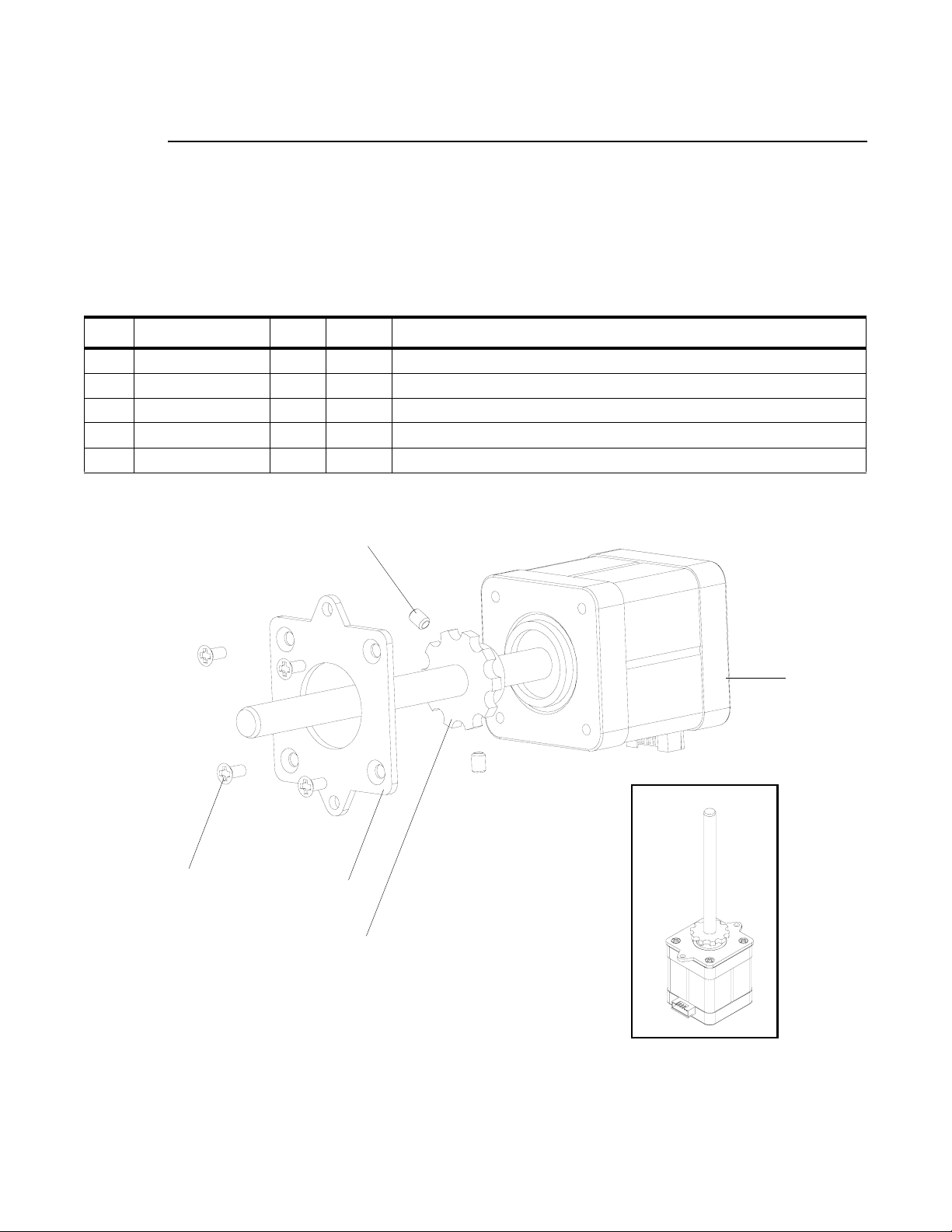
HEAD ASSEMBLY : EDGE MOTOR ASSEMBLY
Edge Motor Assembly
21.9704.0255 Rev. A
Refer to Figure 3-33
No. Item Qty. UM. Description
1 10.9678.0330 1 EA MOTOR ADAPTER PLATE
2 10.9704.0259 1 EA KNOB, EDGE ACTUATION, MANUAL
3 44.9704.0208 1 EA MOTOR, SIZE 17, FOCUS
4 53.6559.0001 4 EA SCREW, 4-40 X 1/4" PFZ
5 53.6578.0002 2 EA SCREW, 6-32 X 3/16" SET CUP PNT
3
4 (x4)*
5 (x2)*
3
1
2
*APPLY LOCTITE 242 TO THREADS PRIOR TO INSTALLATION.
Figure 3-33: Edge Motor Assembly
02.9704.0010 0 75
Page 94
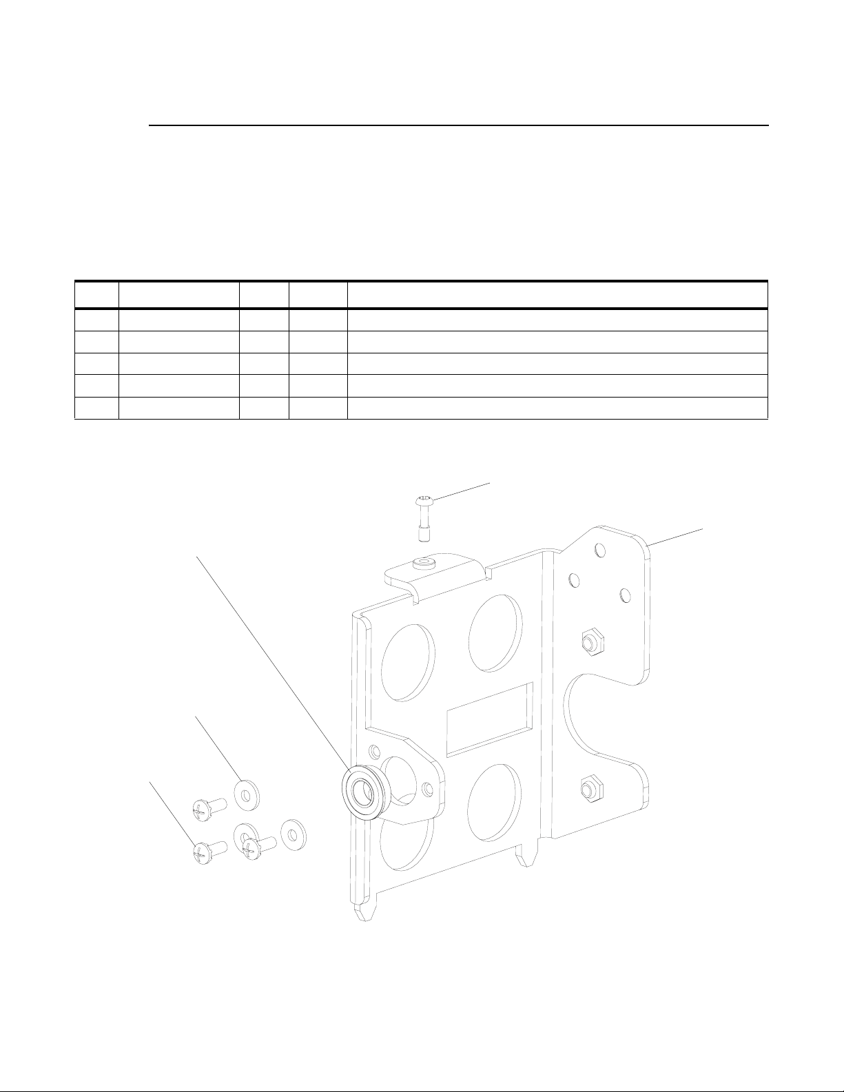
VARI❋LITE - VL4000 SPOT LUMINAIRE SERVICE MANUAL
Gobo Bulkhead Left Bracket Assembly
21.9704.0281 Rev. C
Refer to Figure 3-34
No. Item Qty. UM. Description
1 10.9704.0251 1 EA BRACKET, LEFT, EDGE MOTOR, GOBO BULKHEAD
2 53.6558.0009 3 EA SCREW, 6-32 X 3/8" LG PPZ SEMS
3 53.6685.0500 1 EA SCREW, 6-32 X 1/2 PPB CAPTIVE
4 54.9704.0295 1 EA BEARING, NPB, MR105ZZK13
5 55.6528.0001 3 EA WASHER, #6 FLAT ZINC
2 (x3)
3
1
4
5 (x3)
Figure 3-34: Gobo Bulkhead Left Bracket Assembly
76 02.9704.0010 0
Page 95
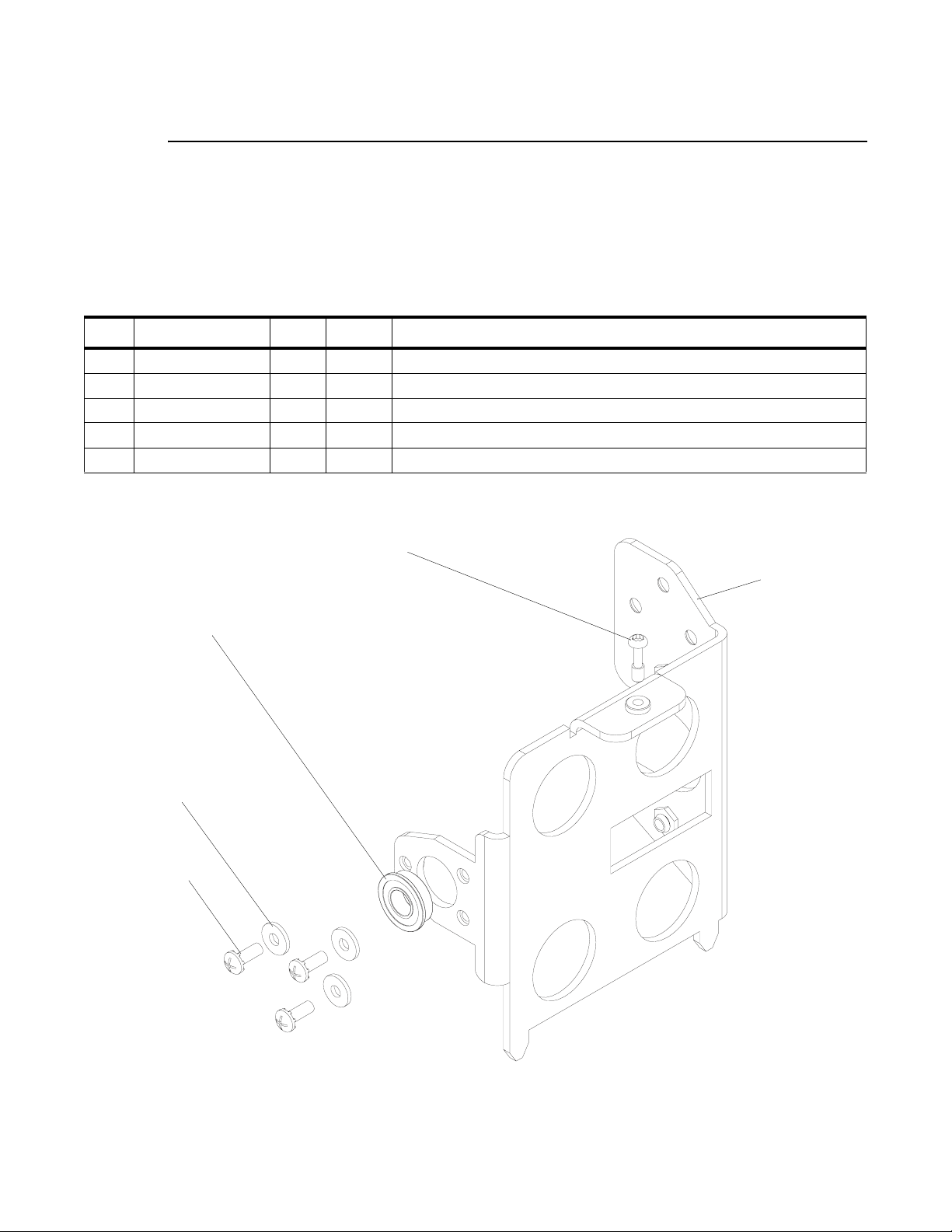
HEAD ASSEMBLY : GOBO BULKHEAD RIGHT BRACKET ASSEMBLY
Gobo Bulkhead Right Bracket Assembly
21.9704.0282 Rev. C
Refer to Figure 3-35
No. Item Qty. UM. Description
1 10.9704.0252 1 EA BRACKET, RIGHT, EDGE MOTOR, GOBO BULKHEAD
2 53.6558.0009 3 EA SCREW, 6-32 X 3/8" LG PPZ SEMS
3 53.6685.0500 1 EA SCREW, 6-32 X 1/2 PPB CAPTIVE
4 54.9704.0295 1 EA BEARING, NPB, MR105ZZK13
5 55.6528.0001 3 EA WASHER, #6 FLAT ZINC
3
5 (x3)
2 (x3)
3
1
4
Figure 3-35: Gobo Bulkhead Right Bracket Assembly
02.9704.0010 0 77
Page 96

VARI❋LITE - VL4000 SPOT LUMINAIRE SERVICE MANUAL
Animation Wheel 1 Assembly
21.9704.1351 Rev. A
Refer to Figure 3-36
No. Item Qty. UM. Description
1 10.9704.0240 1 EA SPACER, 0.197" ID, 0.250" OD, 0.032" THK
2 10.9704.0248 1 EA SPACER, 0.197" ID, 0.250" OD, 0.087" THK
3 10.9704.0313 1 EA INDEX PULLEY, ANIMATION WHEEL
4 10.9704.0319 1 EA FLAG, ANIMATION ARM
5 10.9704.0372 6 EA SPACER, ROLLER, SHUTTER ROTATE
6 10.9704.0373 5 EA SPACER, ROLLER, SHUTTER ROTATE
7 10.9704.1323 1 EA DRIVE PULLEY, ANIMATION WHEEL
8 21.9704.0331 1 EA MOTOR ASSY, ANIMATION WHEEL
9 22.9704.0341 1 EA ASSY, COLOR ANIMATION
10 22.9704.1362 1 EA ARM, ANIMATION WHEEL, BRACED
11 53.6559.0001 3 EA SCREW, 4-40 X 1/4" PFZ
12 53.6578.0002 2 EA SCREW, 6-32 X 3/16" SET CUP PNT
13 53.6659.0002 1 EA SCREW, 2-56 X 1/4" PPZ
14 53.6659.0012 3 EA SCREW, 2-56 X 1/8" PPZ
15 53.6659.0015 4 EA SCREW, 2-56 X 1/4" PFB
16 54.9687.1253 2 EA BEARING, NPB, MR105ZZK13
17 54.9704.0392 1 EA BELT, TIMING, MXL, 225 GRV, 0.125" WD, SILICONE/KEV
18 54.9704.1575 5 EA BEARING, SR188, 0.250" ID, 0.500" OP, 0.125" WD
78 02.9704.0010 0
Page 97
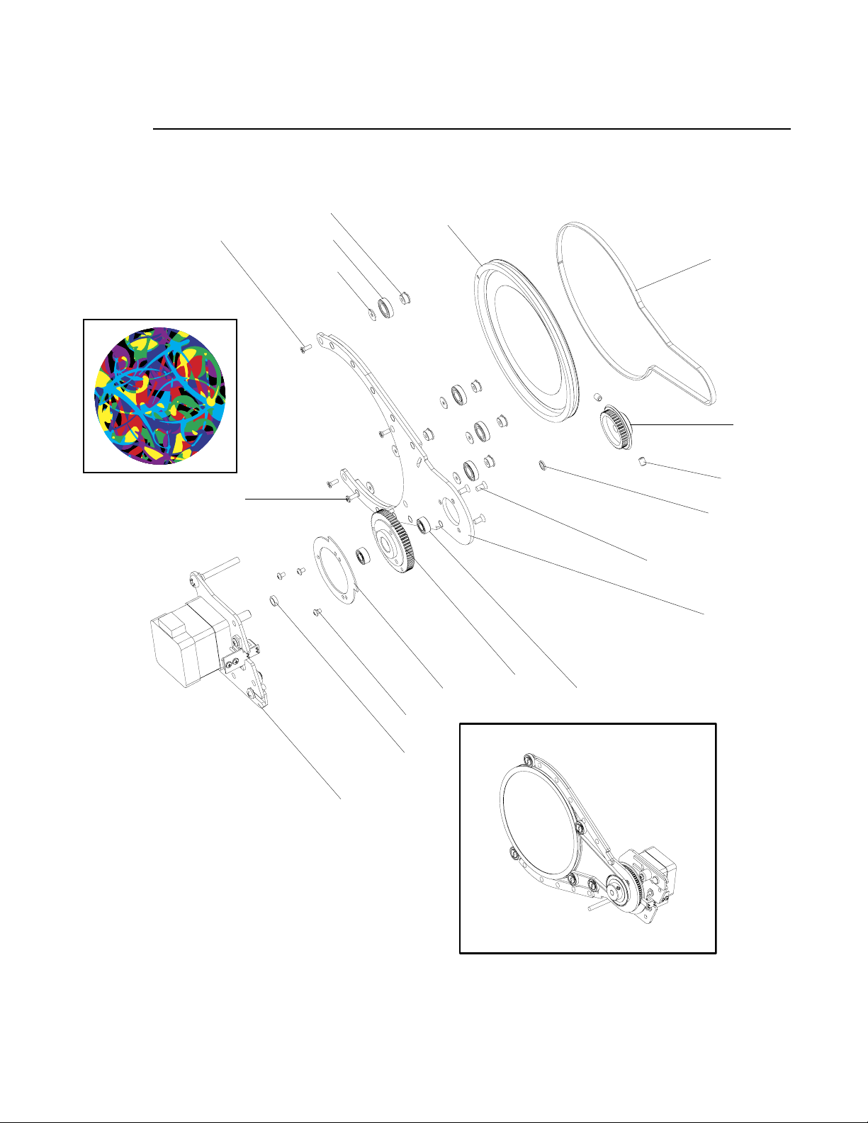
HEAD ASSEMBLY : ANIMATION WHEEL 1 ASSEMBLY
Animation Wheel 1 Assembly (continued)
3
15 (x4)*
13*
6 (x5)
18 (x5)
5 (x6)
9
17
7***
12 (x2)*/***
1
11 (x3)*
14 (x3)*
2
8
*APPLY ONE DROP OF LOCTITE TO SCREW THREADS DURING
INSTALLATION.
**NOTE FLAG ORIENTATION.
***PRESS FIRMLY DOWN ON OUTSIDE PULLEY TO REMOVE
ALL FREE SPACE IN PARTS STACK BEFORE TIGHTENING SET
SCREWS IN OUTSIDE PULLEY. VERIFY THAT THERE IS NO
AXIAL PLAY IN PARTS STACK AFTER SET SCREWS ARE
TIGHTENED.
Figure 3-36: Animation Wheel 1 Assembly
4**
10
3
16 (x2)
02.9704.0010 0 79
Page 98
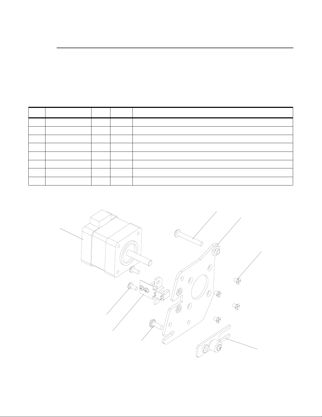
VARI❋LITE - VL4000 SPOT LUMINAIRE SERVICE MANUAL
Animation Wheel 1 Motor Assembly
21.9704.0331 Rev. B
Refer to Figure 3-37
No. Item Qty. UM. Description
1 10.9704.0309 1 EA MOTOR MOUNT, ANIMATION WHEEL 1
2 21.9687.2500 1 EA ASSY, SENSOR, COLOR BULKHEAD
3 21.9704.0239 1 EA ASSY, TENSION ADJUST, ANIMATION WHEEL
4 44.9704.1213 1 EA MOTOR, SIZE 14, SHAFT 24 MM LG
5 53.6513.0054 4 EA SCREW, M3 X .5 X 4 MM LG PFZ METRIC
6 53.6558.0009 1 EA SCREW, 6-32 X 3/8" LG PPZ SEMS
7 53.6571.0002 1 EA SCREW, 6-32 X 1-1/4" LG PPB
8 55.2203.0001 2 EA SCREW, 4-40 X 1/4" PPZ
4
8 (x2)
2
*APPLY LOCTITE 242 TO THREADS PRIOR TO INSTALLATION.
7
1
5 (x4)*
6
3
Figure 3-37: Animation Wheel 1 Motor Assembly
80 02.9704.0010 0
Page 99

HEAD ASSEMBLY : ANIMATION WHEEL 2 ASSEMBLY
Animation Wheel 2 Assembly
21.9704.1352 Rev. A
Refer to Figure 3-38
No. Item Qty. UM. Description
1 10.9704.0240 1 EA SPACER, 0.197" ID, 0.250" OD, 0.032" THK
2 10.9704.0248 1 EA SPACER, 0.197" ID, 0.250" OD, 0.087" THK
3 10.9704.0313 1 EA INDEX PULLEY, ANIMATION WHEEL
4 10.9704.0319 1 EA FLAG, ANIMATION ARM
5 10.9704.0372 6 EA SPACER, ROLLER, SHUTTER ROTATE
6 10.9704.0373 5 EA SPACER, ROLLER, SHUTTER ROTATE
7 10.9704.1323 1 EA DRIVE PULLEY, ANIMATION WHEEL
8 21.9704.0332 1 EA MOTOR ASSY, ANIMATION WHEEL 2
9 22.9704.0342 1 EA ASSY, FIRE/WATER ANIMATION
10 22.9704.1362 1 EA ARM, ANIMATION WHEEL, BRACED
11 53.6559.0001 3 EA SCREW, 4-40 X 1/4" PFZ
12 53.6578.0002 2 EA SCREW, 6-32 X 3/16" SET CUP PNT
13 53.6659.0002 1 EA SCREW, 2-56 X 1/4" PPZ
14 53.6659.0012 3 EA SCREW, 2-56 X 1/8" PPZ
15 53.6659.0015 4 EA SCREW, 2-56 X 1/4" PFB
16 54.9687.1253 2 EA BEARING, NPB, MR105ZZK13
17 54.9704.0392 1 EA BELT, TIMING, MXL, 225 GRV, 0.125" WD, SILICONE/KEV
18 54.9704.1575 5 EA BEARING, SR188, 0.250" ID, 0.500" OP, 0.125" WD
3
02.9704.0010 0 81
Page 100
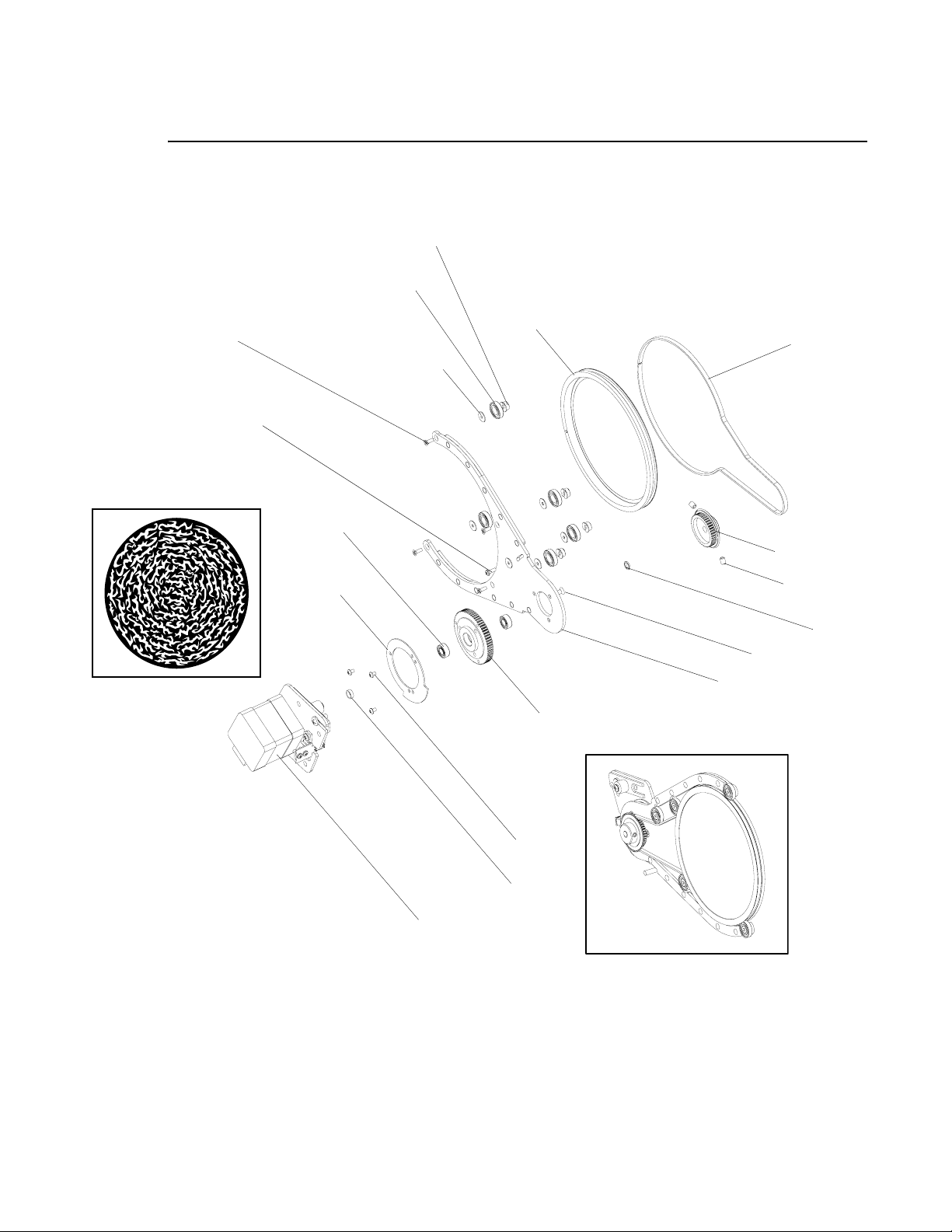
VARI❋LITE - VL4000 SPOT LUMINAIRE SERVICE MANUAL
Animation Wheel 2 Assembly (continued)
6 (x5)
18 (x5)
15 (x4)*
13*
16 (x2)
4**
9
17
5 (x6)
7***
12 (x2)*/***
1
11 (x3)*
10
3
14 (x3)*
2
8
*APPLY ONE DROP OF LOCTITE TO SCREW THREADS DURING INSTALLATION.
**NOTE FLAG ORIENTATION.
***PRESS FIRMLY DOWN ON OUTSIDE PULLEY TO REMOVE ALL FREE SPACE IN PARTS STACK BEFORE
TIGHTENING SET SCREWS IN OUTSIDE PULLEY. VERIFY THAT THERE IS NO AXIAL PLAY IN PARTS STACK
AFTER SET SCREWS ARE TIGHTENED.
Figure 3-38: Animation Wheel 2 Assembly
82 02.9704.0010 0
 Loading...