

Page 1

Philips Respironics V60/V60 Plus Ventilator
Service Manual
Page 2

For technical support and customer service, contact:
USA and Canada: 1-800-722-9377, option 2
International: visit www.healthcare.philips.com, sele
Philips is a part of Royal Philips
© Koninklijke Philips N.V. 2009-2023
ct your location and language, select Contact & Support.
All Rights are reserved. Reproduction in whole or in part
or otherwise is prohibited without the written consent of the copyright holder. Unauthorized copying of this
publication may infringe copyright and reduce the ability of Philips to provide accurate and up-to-date
information to users. Non Philips product names may be trademarks of their respective owners.
Manufacturer
Respironics Inc.
1001 Murry Ridge Lane
Murrysville, PA 15668
USA
Respironics Inc. reserves the right to make changes to both this service manual and to the product it
scribes. Product specifications are subject to change without notice. Nothing contained within this service
de
manual is intended as any offer, warranty, promise or contractual condition, and must not be taken as such.
in any form or by any means, electrical, mechanical
1049766 T 98
9805612651
Page 3

Table of Contents
1 Introduction and Intended Use .................................................. 9
1.1 Intended Use ...................................................................................................10
1.2 Recommended Test Equipment, Tools, and Supplies ......................................11
1.3 Symbols ...........................................................................................................15
1.4 Where to Go for Help ......................................................................................21
2 Warnings, Cautions, and Notes ................................................ 23
2.1 General ............................................................................................................24
2.2 Preparing for Ventilation .................................................................................28
2.3 Operation .........................................................................................................31
2.4 Operation in High Flow Therapy (HFT) ............................................................32
2.5 Alarms and Messages ......................................................................................32
2.6 Care and Maintenance ....................................................................................33
2.7 Internal Battery ................................................................................................34
2.8 First-Time Installation ......................................................................................35
2.9 Communications Interface ..............................................................................36
2.10 Diagnostic Mode ..............................................................................................36
3 Theory of Operation ................................................................ 37
3.1 Pneumatics ......................................................................................................38
3.1.1 Air Inlet ............................................................................................39
3.1.2 Air Inlet Filter ...................................................................................39
3.1.3 Air Flow Sensor ................................................................................40
3.1.4 Machine and Proximal Pressure Transducers ..................................40
3.1.5 Barometric Pressure Transducer ......................................................40
3.1.6 O
3.1.7 Manifold, O
3.1.8 O
3.1.9 O
3.1.10 Blower ..............................................................................................41
3.1.11 Solenoid Valves ................................................................................42
3.2 Electronics .......................................................................................................43
3.2.1 Power Management (PM) PCBA ......................................................43
3.2.2 Power Supply ...................................................................................44
3.2.3 Internal Battery ................................................................................44
3.2.4 CPU PCBA .........................................................................................45
3.2.5 Motor Controller (MC) PCBA ............................................................48
3.2.6 Data Acquisition (DA) PCBA .............................................................48
3.2.7 Primary Speakers .............................................................................48
3.2.8 Flow Sensors ....................................................................................49
3.2.9 User Interface (UI) ............................................................................49
3.2.10 LCD Assembly ...................................................................................49
Pressure Transducer ....................................................................40
2
Inlet Filter, Filter Element ............................................41
2
Solenoid Valve .............................................................................41
2
Flow Sensor .................................................................................41
2
1049766 T V60/V60 Plus Ventilator Service Manual 3
Page 4

Table of Contents
3.2.11 Backlight Inverter PCBA ................................................................... 50
3.2.12 Touchscreen Assembly .................................................................... 50
3.2.13 Nav-ring Assembly/Accept Button ................................................... 50
3.2.14 Power Switch Overlay ...................................................................... 51
3.2.15 Switch PCBA ..................................................................................... 51
3.2.16 UI PCBA ............................................................................................ 51
3.3 Electronic Signal Paths .................................................................................... 52
4 Ventilator Installation ............................................................. 59
4.1 Assembly and Installation ............................................................................... 60
4.2 Record Ventilator Information ........................................................................ 61
4.3 Electrical Safety ............................................................................................... 62
4.4 Preoperational Check ...................................................................................... 62
4.5 Preparing the Ventilator for Use ..................................................................... 64
4.6 Electrical Safety/Preoperational Check Form .................................................. 65
5 Maintenance ........................................................................... 67
5.1 Exterior and Touchscreen Cleaning ................................................................. 70
5.1.1 Approved Cleaning Agents .............................................................. 70
5.1.2 Cleaning Instructions ....................................................................... 70
5.2 Exterior and Touchscreen Disinfection ............................................................ 71
5.2.1 Approved Disinfecting Agents ......................................................... 71
5.2.2 Disinfecting Instructions .................................................................. 71
5.3 Annual Preventive Maintenance Instructions ................................................. 72
5.4 Storage ............................................................................................................ 75
5.5 Repacking and Shipping .................................................................................. 75
5.6 Disposal ........................................................................................................... 76
5.6.1 Transferring the Product to Another Owner .................................... 76
5.6.2 Final Disposal of the Product ........................................................... 76
6 Diagnostic Mode and Troubleshooting .................................... 77
6.1 System Settings ............................................................................................... 79
6.1.1 Selecting a Language ....................................................................... 80
6.1.2 Setting Date and Time ..................................................................... 82
6.1.3 Restoring Default Settings ............................................................... 83
6.1.4 Selecting Pressure Units .................................................................. 84
6.1.5 Enabling Software Options .............................................................. 85
6.1.6 Baud Rate ........................................................................................ 86
6.1.7 Alarm Volume Escalation ................................................................. 87
6.2 Service ............................................................................................................. 88
6.2.1 Viewing Ventilator Information ....................................................... 88
6.2.2 Pneumatic Controls ......................................................................... 89
6.2.3 Output Controls ............................................................................... 91
6.2.4 Miscellaneous .................................................................................. 92
6.3 Touchscreen Calibration .................................................................................. 96
6.4 Diagnostic Codes, Alarms, and Troubleshooting ............................................. 97
6.5 Symptom-Based Troubleshooting ................................................................. 111
4 V60/V60 Plus Ventilator Service Manual 1049766 T
Page 5

6.6 Miscellaneous Troubleshooting Tips .............................................................112
6.7 Battery Troubleshooting Tips .........................................................................115
7 Reports and Software Downloads .......................................... 117
7.1 Setting Up the Service PC ..............................................................................118
7.2 Generating a Diagnostic Report (DRPTA) .......................................................126
7.3 Generating a Flow Sensor Zero Calibration Report (FSZR) .............................128
7.4 Clearing the Significant Event Log .................................................................129
7.5 Downloading Ventilator Software .................................................................130
7.5.1 Downloading Software from InCenter ...........................................130
7.5.2 Downloading Software to the Ventilator .......................................134
7.6 Programming the Ventilator Serial Number and Power-On Hours ................137
7.6.1 Programming the Ventilator Serial Number ..................................137
7.6.2 Programming Ventilator Power-On Hours .....................................138
8 Part Removal and Installation ................................................ 139
8.1 Disconnecting All Power ................................................................................141
8.2 Air Inlet Filter .................................................................................................142
8.3 Internal Battery ..............................................................................................143
8.4 Top Cover .......................................................................................................145
8.5 AC Inlet ..........................................................................................................146
8.6 Fan .................................................................................................................147
8.7 O
8.8 DA PCBA to MC PCBA Cable ...........................................................................149
8.9 MC PCBA Retention Bracket ..........................................................................150
8.10 Motor Controller (MC) PCBA .........................................................................151
8.11 Separating the UI from the Base ...................................................................153
8.12 Front Panel ....................................................................................................154
8.13 Gas Outlet Port ..............................................................................................155
8.14 UI Retainer .....................................................................................................155
8.15 Proximal Pressure Port ..................................................................................156
8.16 Alarm Speakers ..............................................................................................157
8.17 Power Management (PM) PCBA ....................................................................158
8.18 Power Supply .................................................................................................160
8.19 CPU PCBA .......................................................................................................164
8.20 Real-Time Clock Battery .................................................................................165
8.21 Left Side Wall .................................................................................................166
8.22 Gas Delivery Subsystem (GDS) .......................................................................167
8.23 Right Side Wall ...............................................................................................169
8.24 O
8.25 Data Acquisition (DA) PCBA ...........................................................................171
8.26 Solenoid Valves ..............................................................................................173
8.27 O
8.28 Air and O
8.29 Blower ...........................................................................................................177
Inlet Fitting ................................................................................................148
2
8.18.1 1st Generation Power Supply and Shroud .....................................161
8.18.2 2nd Generation Power Supply and Shroud ....................................162
Inlet Filter ..................................................................................................170
2
Solenoid Valve ...........................................................................................174
2
Flow Sensor Assembly ..................................................................175
2
Table of Contents
1049766 T V60/V60 Plus Ventilator Service Manual 5
Page 6

Table of Contents
8.30 Opening the User Interface (UI)/Rear Bezel .................................................. 178
8.31 Power Switch Overlay .................................................................................... 179
8.32 Switch PCBA .................................................................................................. 180
8.33 Front Bezel, Touchscreen .............................................................................. 181
8.34 LCD ................................................................................................................ 183
8.34.1 Original (HYDIS) LCD ...................................................................... 183
8.34.2 2nd-Generation (NEC) LCD ............................................................ 185
8.35 User Interface (UI) PCBA ............................................................................... 187
8.35.1 Original UI PCBA ............................................................................ 187
8.35.2 2nd-Generation UI PCBA ............................................................... 188
8.36 Backlight Inverter PCBA ................................................................................. 189
8.37 LCD Tray ......................................................................................................... 189
8.38 Bottom Feet .................................................................................................. 190
8.38.1 Removing Bottom Feet Configured for the Universal Stand ..........190
8.38.2 Converting Ventilator Feet
(Universal Stand to V60/V60 Plus Stand) ....................................... 191
8.39 Labels ............................................................................................................ 192
8.40 Component Replacement Data Form ............................................................ 197
9 Performance Verification .......................................................199
9.1 Performance Verification Tests ...................................................................... 200
9.2 Pneumatic Calibration Analyzer Setup .......................................................... 205
9.2.1 Measurement Selection Screen ..................................................... 205
9.2.2 Averaging Setup Menu .................................................................. 207
9.2.3 Trigger Options .............................................................................. 208
9.2.4 Configurations ............................................................................... 209
9.3 Preliminary Procedures ................................................................................. 212
9.3.1 Cleaning and Inspection ................................................................ 212
9.3.2 Touchscreen Calibration ................................................................ 212
9.3.3 Record Ventilator Information ....................................................... 213
9.4 Test 1: Electrical Safety .................................................................................. 215
9.5 Test 2: Leak Tests ........................................................................................... 217
9.5.1 High Pressure Leak Test ................................................................. 217
9.5.2 System Leak Test ............................................................................ 219
9.6 Test 3: Controls .............................................................................................. 221
9.7 Test 4: Pressure Accuracy .............................................................................. 223
9.7.1 Pressure Accuracy Test Example .................................................... 226
9.8 Test 5: Air Delivery ........................................................................................ 228
9.9 Test 6: Flow Sensor Zero Calibration ............................................................. 232
9.10 Test 7: Air Flow Accuracy ............................................................................... 234
9.11 Test 8: O
9.12 Test 9: O
9.13 Test 10: S/T Performance .............................................................................. 244
9.14 Test 11: Alarms .............................................................................................. 246
9.15 Test 12: Power Fail ......................................................................................... 248
9.15.1 Power Fail Test - Internal Battery Installed .................................... 248
9.15.2 Power Fail Test - Internal Battery Not Installed ............................. 250
9.16 Test 13: Internal Battery ................................................................................ 251
Flow Accuracy ............................................................................... 237
2
Mix Accuracy ................................................................................. 240
2
6 V60/V60 Plus Ventilator Service Manual 1049766 T
Page 7

9.17 Preparing the Ventilator for Use ....................................................................253
9.18 Performance Verification Troubleshooting/Repair ........................................255
9.18.1 Test 1: Electrical Safety ...................................................................255
9.18.2 Test 2: Leak Tests ............................................................................256
9.18.3 Test 3: Controls ..............................................................................256
9.18.4 Test 4: Pressure Accuracy ...............................................................257
9.18.5 Test 5: Air Delivery .........................................................................257
9.18.6 Test 6: Flow Sensor Zero Calibration ..............................................257
9.18.7 Test 7: Air Flow Accuracy ...............................................................257
9.18.8 Test 8: O
9.18.9 Test 9: O
Flow Accuracy ................................................................258
2
Mix Accuracy ..................................................................258
2
9.18.10 Test 10: S/T Performance ...............................................................258
9.18.11 Test 11: Alarms ...............................................................................259
9.18.12 Test 12: Power Fail .........................................................................259
9.18.13 Test 13: Internal Battery .................................................................259
9.19 Electrical Safety Data Form ............................................................................261
9.20 Performance Verification Data Form .............................................................263
A Replacement Parts ................................................................ 271
A.1 Complete Parts List ........................................................................................273
A.2 Recommended Inventory Parts List ...............................................................281
A.3 Accessory Part Numbers ................................................................................293
A.4 O
A.5 Universal Stand ..............................................................................................295
A.6 V60 Stand ......................................................................................................298
Manifolds and Hoses .................................................................................294
2
Table of Contents
B Specifications ........................................................................ 301
B.1 Control Settings .............................................................................................302
B.2 Controls Active in V60/V60 Plus Ventilation Modes ......................................303
B.3 Patient Data ...................................................................................................304
B.4 Alarms ............................................................................................................305
B.5 Alarm-Related Specifications .........................................................................306
B.6 Menu Window Settings .................................................................................307
B.7 Operator-Accessible Diagnostic Mode Functions ..........................................308
B.8 Physical Characteristics ..................................................................................309
B.9 Environmental Specifications ........................................................................310
B.10 Pneumatic Specifications ...............................................................................311
B.11 Accessory Requirements ...............................................................................312
B.12 Electrical Specifications .................................................................................313
B.13 Other Specifications ......................................................................................314
C Service Bulletins .................................................................... 315
C.1 Downloading Bulletins from InCenter ...........................................................315
Index ..................................................................................... 317
1049766 T V60/V60 Plus Ventilator Service Manual 7
Page 8

Table of Contents
8 V60/V60 Plus Ventilator Service Manual 1049766 T
Page 9

1
Introduction and Intended Use
1.1 Intended Use .......................................................................................................10
1.2 Recommended Test Equipment, Tools, and Supplies ............................................11
1.3 Symbols ...............................................................................................................15
1.4 Where to Go for Help ...........................................................................................21
1049766 T V60/V60 Plus Ventilator Service Manual 9
Page 10

The Philips Respironics V60/V60 Plus ventilator is a microprocessor-controlled, positive
pressure ventilator assist system. The ventilator provides noninvasive and invasive
ventilatory support for spontaneously breathing adult and pediatric patients.
The ventilator has a variety of modes and monitoring capabilities to assist in assessing
performance and patient-to-ventilator synchrony. Safety features include in-depth alarms
and a variety of integrated safety and self-diagnostic features. The ventilator automatically
checks many system functions at startup and during operation.
The ventilator includes a touchscreen user interface (UI) that lets the operator select
entilator and alarm settings and displays of ventilator and patient data.
v
The ventilator is designed to be upgradeable, and features communications capabilities and
an
internal backup battery.
Read this manual thoroughly before performing service or maintenance on the ventilator.
T
his manual includes advanced troubleshooting, calibration, and maintenance instructions
for the ventilator. All maintenance and repair work should be performed by qualified
biomedical technicians who have appropriate training and authorization to provide
maintenance, repair, and service for the ventilator.
Review the operating instructions for the ventilator before running tests, checking
rational readiness, or initiating patient use. These instructions include important
ope
information about ventilator safety and operation.
For additional information about accessories or related equipment, such as humidifiers and
ote alarm systems, refer to the appropriate instruction manual prior to operating the
rem
ventilator. Review the applicable warnings and cautions in the ventilator user manual before
operating the ventilator.
1.1 Intended Use
The V60/V60 Plus ventilator is an assist ventilator and is intended to augment patient
breathing. In high flow therapy (HFT), the ventilator can also provide respiratory support.
the ventilator is intended for spontaneously breathing individuals who require mechanical
ventilation and respiratory support: patients with respiratory failure, chronic respiratory
insufficiency, or obstructive sleep apnea in a hospital or other institutional settings under
the direction of a physician.
The ventilator is intended to support pediatric patients weighing 20 kg/44 lb or greater to
patients. It is also intended for intubated patients meeting the same selection criteria
adult
as the noninvasive applications. The ventilator is intended to be used by qualified medical
professionals such as physicians, nurses, and respiratory therapists. The ventilator is
intended to be used only with various combinations of Philips-recommended patient
circuits, interfaces (masks), humidifiers, and other accessories.
10 V60/V60 Plus Ventilator Service Manual 1049766 T
Page 11

1.2 Recommended Test Equipment, Tools, and Supplies
Tabl e 1-1 (V60 ventilator service kit) and Tab le 1-2 (other equipment and supplies)
summarize the test equipment required to service the ventilator. Check the calibration
tatus of all test equipment before use.
s
NOTE: The following items are not included in the service kit and must be ordered separately
(see Table 1-2):
• Breathing circuit, single-limb with DEP
• Exhalation port, Whisper Swivel II, reusable
hose kit
•O
2
• Test lung, hard-sided
Table 1-1: V60 Ventilator Service Kit Contents
Description Part number Order number
V60 ventilator service kit: 1054291 453561512121
Adapter, 22-mm to 22-mm 1002505 453561506281
Adapter, remote alarm test cable 1027817 453561507991
Adapter, test, 0.25-in. 332353 453561517281
Adapter, torque, GDS air inlet collar 1111163 453561531671
Adapter, USB to serial 1022895 989805643371
Cable, HIS/EMR null modem 1080588 989805629921
Cable, remote alarm test 1027818 453561508001
Cable, TTL communications 1058778 453561512951
Coupling, straight silicone 500-1000-43 453561505771
Forceps, locking, plastic 1058432 453561512941
O2 regulator/shut-off valve (requires O2 hose kit) 1122489 989805654391
Plug, low-pressure 1058270 453561512911
Plug, tapered, 23/32 - 61/
Plug, tapered, 9/16 - 3/4 in., silicone 1055323 453561512741
Pressure pick-off assembly -- --
Pressure pick-off port (O2 enrichment attachment) 312710 989805609421
Pressure pick-off tubing -- --
Syringe, system leak test 1058271 453561512921
Tubing, 18-in. smooth-bore, package of 2 1003660 453561507701
in., silicone 1055322 453561512731
64
Valve, ball 1058431 453561512931
1049766 T V60/V60 Plus Ventilator Service Manual 11
Page 12

Adapter, 22-mm to
22-mm
Adapter, remote alarm
test cable
Adapter, test, 0.25-in. Adapter, torque, GDS air
inlet collar
Adapter, USB to serial
Cable, HIS/EMR
null modem
O
regulator/shut-off
2
valve
Cable, remote alarm test Cable, TTL
communications
Plug, low-pressure Plug, tapered, 22/32 -
61/64 in. ID, silicone
Coupling, straight
silicone
Plug, tapered,
9/16 - 3/4-in., silicone
Pressure pick-off port Pressure pick-off tubing Syringe, system leak test Tubing, 18-in. smooth-
bore, package of 2
Forceps, locking, plastic
Pressure pick-off
assembly
Val ve, b all
12 V60/V60 Plus Ventilator Service Manual 1049766 T
Page 13
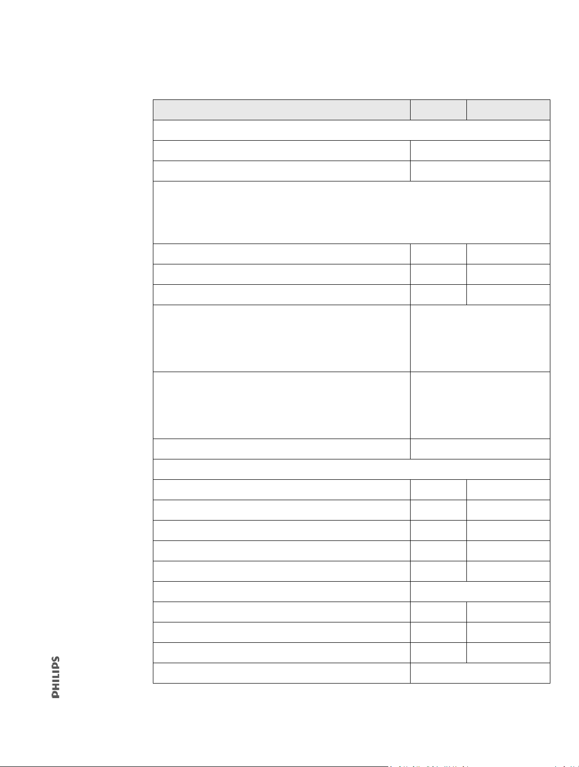
Table 1-2: Other Equipment and Supplies
Description Part number Order number
Test equipment:
Digital multimeter (DMM) accurate to three decimal places Local supplier
Electrical safety analyzer, Fluke ESA620 or equivalent Local supplier
Pneumatic calibration analyzer (measures flow, barometric and ventilator pressures, O
%, and frequency),
2
TSI Certifier FA Plus System or equivalent, including:
NOTE
The Certifier FA Plus System is only available through the commercial channel or your local supplier.
• Controller (TSI model no. 4089) 1154171 989805689961
• High-flow module (TSI model no. 4081) 1037696 989805612971
•O
sensor kit (TSI model no. 4073) 1037156 989805612921
2
Temperature/humidity monitor, capable of measuring:
• Relative humidity: 25% to 98%; resolution: 1%; accuracy: ± 3.5%
(midrange) to ± 5.5% (outside midrange).
Local supplier
• Temperature: 0.0°C to 50.0°C (32.0°F to 122.0°F); resolution
± 0.1°C; accuracy: ± 1°C (± 1.8°F).
Test lung, 1-L, IngMar QuickLung or equivalent, capable of compliance
and resistance:
• C20 (C6) 0.2 (0.06) L/kPa ± 10% at 500 (200) mL tidal volume.
Local supplier
• Rp20 K 17.61 ± 20% (equivalent orifice size = 5.31 mm) pressure
drop 17.61 cmH
O at 1 L/s.
2
Timer Local supplier
Service tools and supplies:
Breathing circuit, single-limb with DEP (x10)
582073 989805609611
Breathing circuit, single-limb with DEP and FEP (x10) 1065832 989805621321
Breathing circuit, single-limb with DEP and FEP (x10) 1065830 989805621311
Exhalation port, Whisper Swivel II, reusable 332113 989805617951
Fitting, system leak test syringe (replacement) 1060263 453561512961
Isopropyl alcohol, 70% Local supplier
Label, electrical safety (x20) 1098020 453561528311
Label, preventive maintenance (x20) 1098019 453561528301
Lubricant, Dupont, KRYTOX GPL 226 1101835 453561529261
Hex drivers (rounded ends), 1.5 to 4 mm Local supplier
1049766 T V60/V60 Plus Ventilator Service Manual 13
Page 14
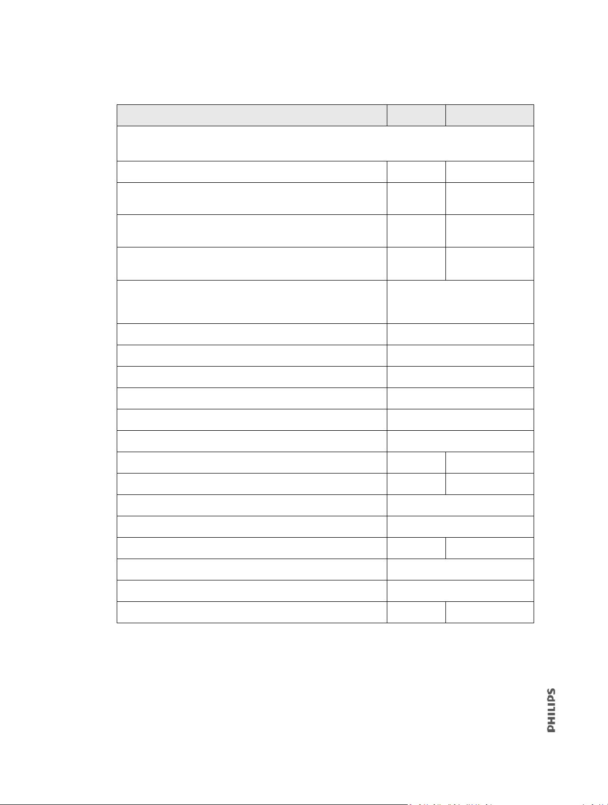
Table 1-2: Other Equipment and Supplies (Continued)
O2 hose kit
Use one hose kit with the O
Description Part number Order number
/regulator shut-off valve (hose kits are not included in the V60 service kit)
2
•Hose kit, O
•Hose kit, O
, DISS female x DISS female (US) 1122456 989805654361
2
, DISS female x NIST socket, DISS female x NIST probe
2
1122488 989805654381
(EMEA)
•Hose kit, O
2
, DISS male x DISS male, DISS male x DISS female
1123977 989805654401
(Canada)
•Hose kit, O2, DISS female x SIS socket, DISS female x NIST probe
1122457 989805654371
(Australia)
PC or laptop (required for downloading software and capturing
diagnostic codes), Windows 7 or newer operating system with serial or
Local supplier
USB ports
Pliers, channel lock Local supplier
Pliers, needle-nose Local supplier
Screwdriver, #0 Phillips Local supplier
Screwdriver, #1 Phillips Local supplier
Socket, deep, 7-mm Local supplier
Socket, deep, 3/16-in., 1/4-in., 5/16-in., 3/8-in., 9/16-in., and 9-32-in. Local supplier
Test lung, hard-sided 1021671 989805611871
Tool, plug, blockout, RJ45 1116109 453561533851
Torque driver, capable of (8.5 to 203.4 N-cm) (0.75 to 18 in.-lb) Local supplier
Torque driver, capable of (361.6 to 621.4 N-cm) (32 to 55 in.-lb) Local supplier
Tubing, Tygon, ID 1/8 in., OD 1/4 in., 5 ft L 1121145 453561535011
Vacuum, ESD-safe, 3M Model 497-AJM or equivalent Local supplier
Workstation, antistatic, 3M Model 725 or equivalent Local supplier
Wrench, roll stand caster, 17-mm thin 1096352 453561528181
14 V60/V60 Plus Ventilator Service Manual 1049766 T
Page 15
1.3 Symbols
MD
UDI
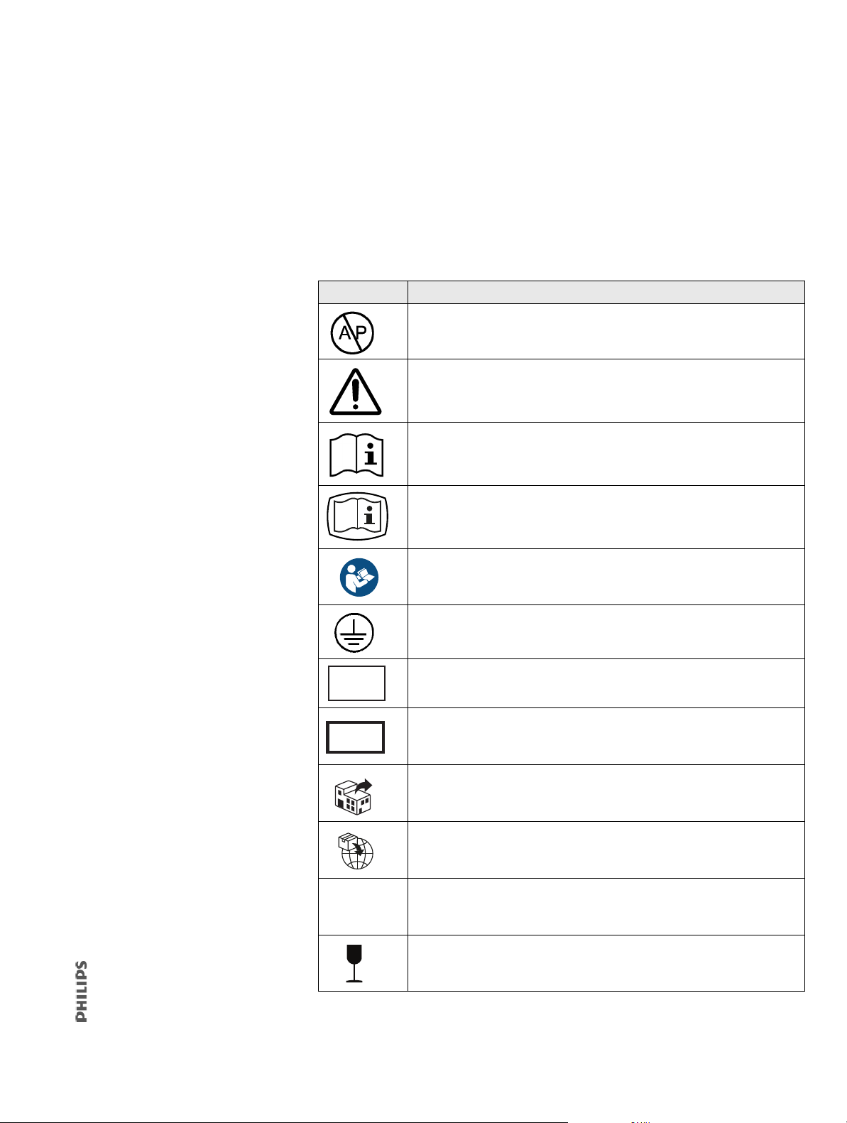
Refer to these tables to interpret symbols used on the ventilator labels, backup battery
labels, and packaging. In addition, Philips provides a Symbol Library at:
http://symbols.philips.com. To interpret symbols pert
instructions for use.
?
Table 1-3: Symbols on Ventilator Labels, Battery, and Packaging
Symbol Description
Warning: Risk of explosion. Do not use in the presence of flammable
anesthetics.
Attention, consult the accompanying documents.
Read the user manual before using the ventilator. Symbol may be
accompanied by the web address www.Philips.com/IFU to indicate access
to electronic IFUs.
Electronic instructions for use. Indicates that relevant information for use
of the product is available in electronic form.
aining to accessories, refer to their
(Blue) It is mandatory for the operator to consult the accompanying
documents.
Protective earth (ground)
Medical device
Unique device identifier
Distributor. Symbol accompanied by address
Importer. Symbol accompanied by address
This medical device contains substances that can be carcinogenic,
mutagenic, reprotoxic (CMR), or substances with endocrine-disrupting
properties.
Fragile
1049766 T V60/V60 Plus Ventilator Service Manual 15
Page 16
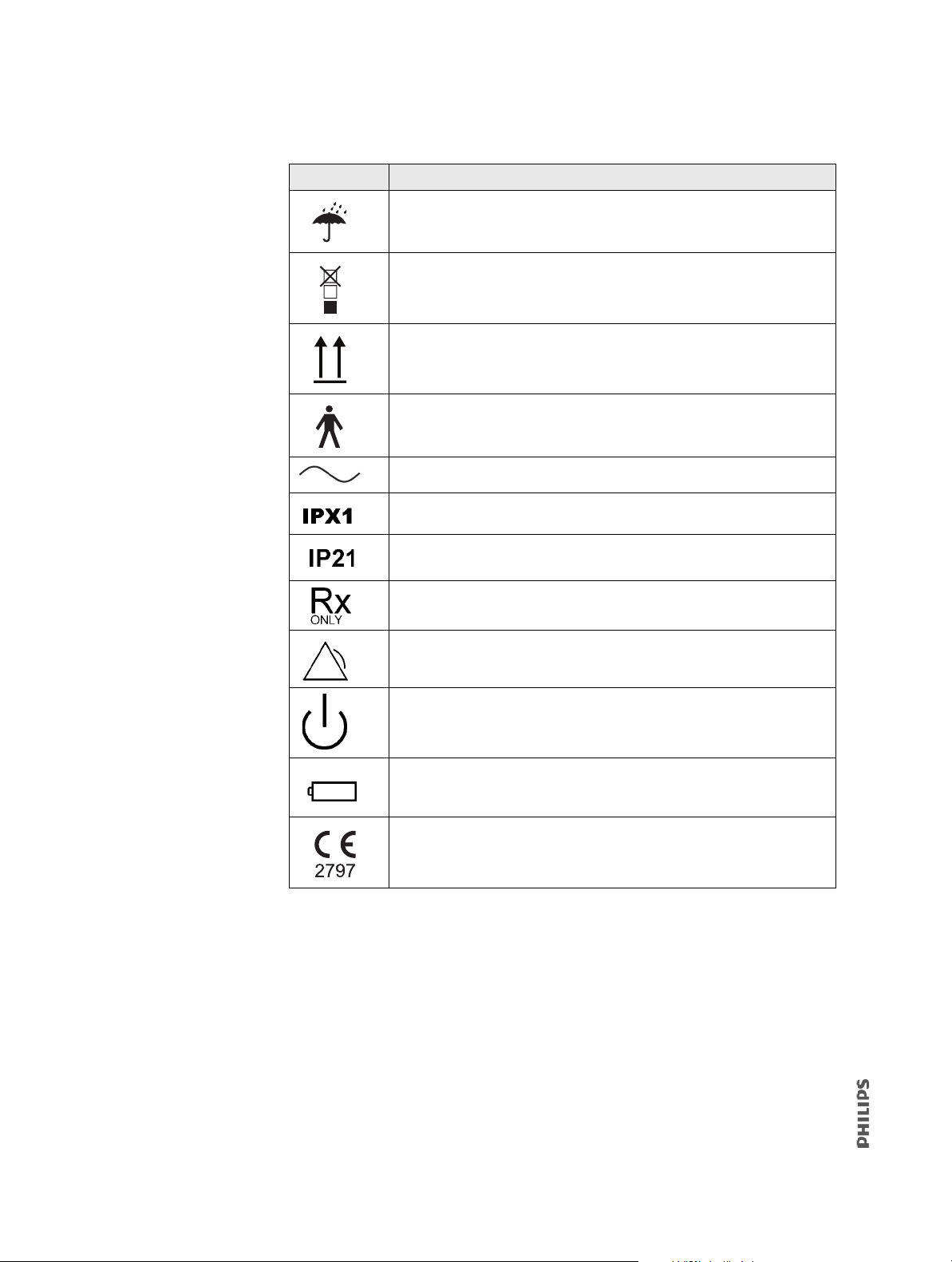
Table 1-3: Symbols on Ventilator Labels, Battery, and Packaging (Continued)
2
Symbol Description
Keep dry
Stacking limit by number
This end up
Type B applied part, which is equipment that provides a particular degree
of protection against electric shock, particularly in regard to allowable
leakage current and of the protective earth connection
Requires alternating current (AC)
Degree of fluid ingress protection provided by the enclosure (drip-proof)
Degree of solid object protection and fluid ingress protection provided by
the enclosure (drip-proof)
Caution: Federal law restricts this device to sale by or on the order of a
physician
Alarm and remote alarm
Two states of control: ON and Shutdown
Battery
European Conformity. Symbol is on rear panel of ventilator.
16 V60/V60 Plus Ventilator Service Manual 1049766 T
Page 17
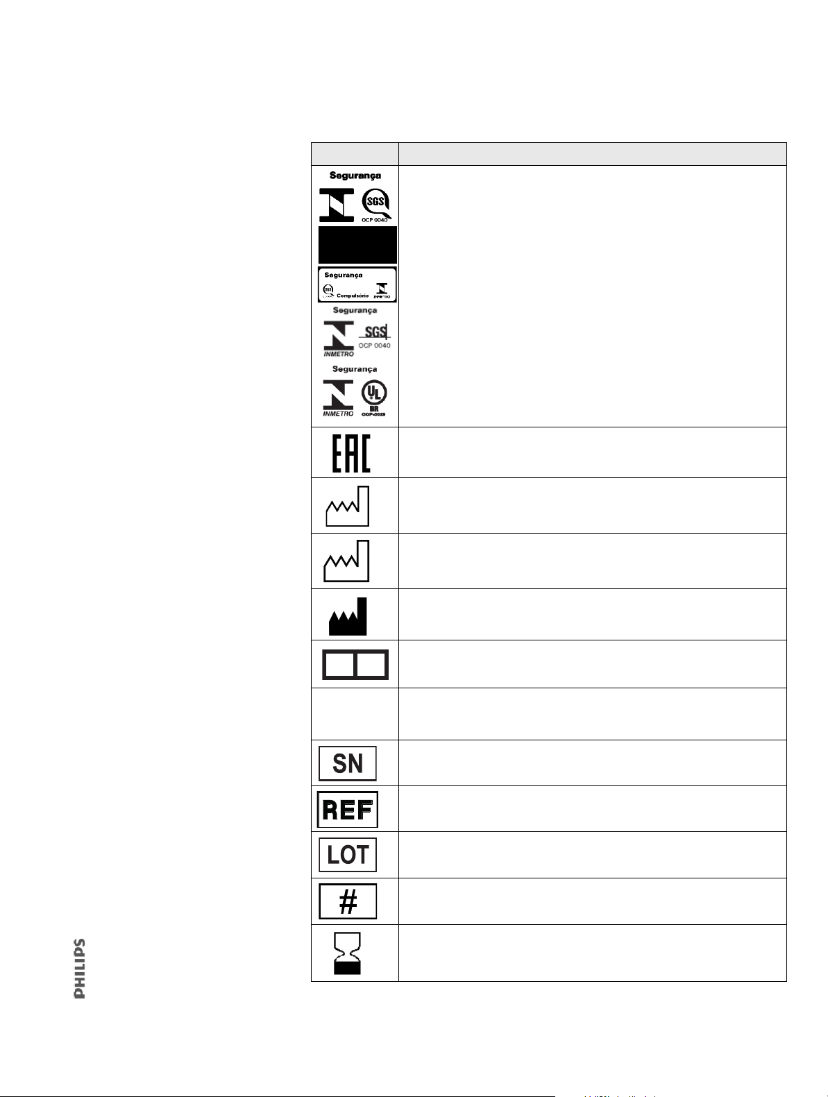
Table 1-3: Symbols on Ventilator Labels, Battery, and Packaging (Continued)
US
EC REP
Symbol Description
Brazilian Conformity. Certification by INMETRO (National Institute of
Metrology, Standardization and Industrial Quality)/SGS (Societe Generale
de Surveillance). One of these symbols, depending upon available space.
EurAsian Conformity mark - EAC
Date of manufacture. Symbol accompanied by date.
Country of Manufacture. Symbol accompanied by country code (and
optionally manufacture date and/or manufacturer’s name and address).
Manufacturer. Symbol accompanied by manufacturer’s
name and address.
EC representative
Indicates a medical device that contains substances that can be
carcinogenic, mutagenic, reprotoxic (CMR), or substances with endocrine
disrupting properties.
Serial number
Order number
Lot or batch number
Model number
Use by date
1049766 T V60/V60 Plus Ventilator Service Manual 17
Page 18
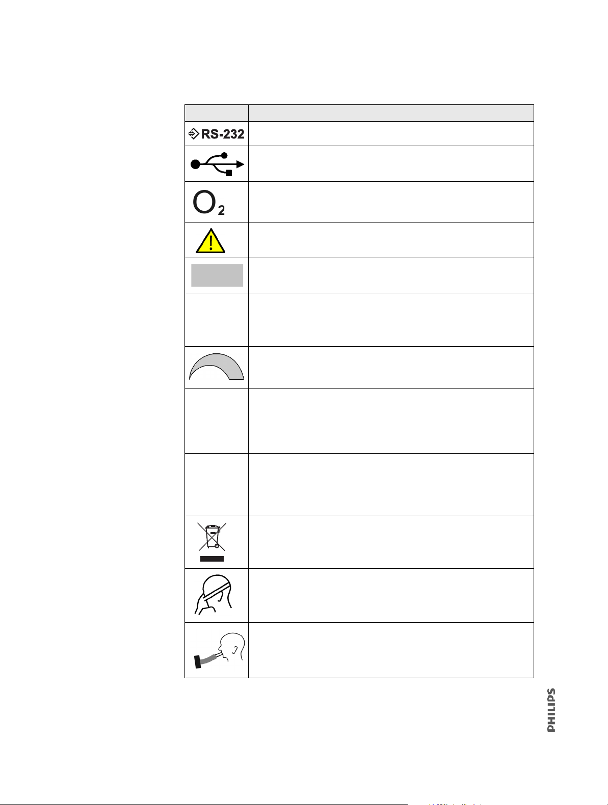
Table 1-3: Symbols on Ventilator Labels, Battery, and Packaging (Continued)
Symbol Description
RS-232 serial input/output
USB port
Oxygen
(Yellow) Warning
Ethernet connection
Accept button. If the nav-ring is present, the Accept button is on the navring.
Adjustment direction on the nav-ring (if present)
ETL certification mark
Do not disassemble. Refer to authorized service personnel.
Product must be disposed of in accordance with the WEEE directive.
Noninvasive ventilation (patient with mask)
Invasive ventilation (intubated patient)
18 V60/V60 Plus Ventilator Service Manual 1049766 T
Page 19
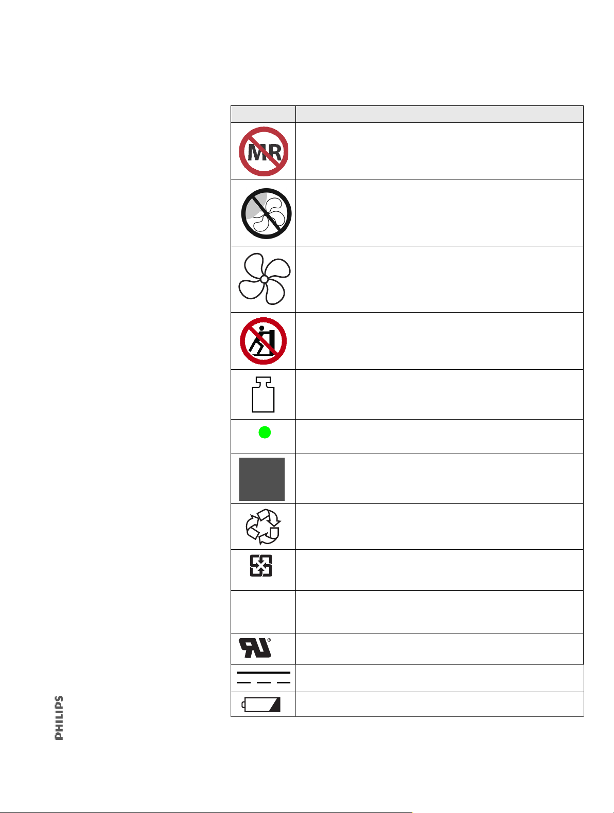
Table 1-3: Symbols on Ventilator Labels, Battery, and Packaging (Continued)
(On power cord)
廢電池請回收
Symbol Description
The ventilator is MR Unsafe and presents a projectile hazard. Keep the
ventilator outside MRI scan room (Zone IV).
Do not block the cooling fan Inlet (at the rear of the ventilator).
Used in conjunction with the blue “consult accompanying documents”
symbol to indicate “Do not block the cooling fan Inlet.”
No pushing. Do not push on the ventilator screen. Tipping hazard.
Total mass (weight). See section B.8 for details on physical characteristics of
the ventilator, stand, and accessories.
Hospital-grade
Packaging unit. Symbol accompanied by a number (indicating the number
of pieces in the package).
Recycle
Recycle (Taiwan)
RoHS (China). Administrative Measure on the Control of Pollution Caused
by Electronic Information Products. Contains RoHS substances with 50
years environmentally friendly use period (EFUP).
uR UL recognition symbol
Direct current (DC). Symbol is on backup battery.
Battery check.
1049766 T V60/V60 Plus Ventilator Service Manual 19
Page 20
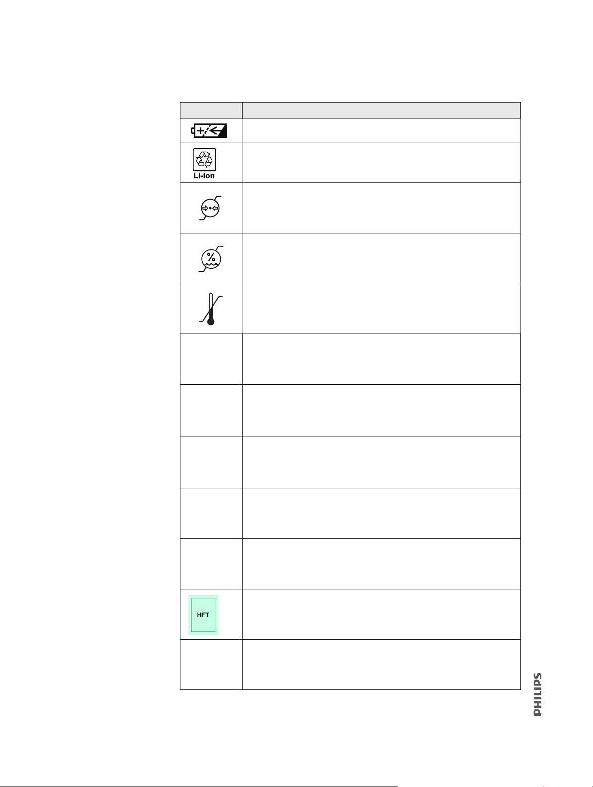
Table 1-3: Symbols on Ventilator Labels, Battery, and Packaging (Continued)
+50 ÛC
-20 ÛC
Symbol Description
Rechargeable battery. Symbol is on backup battery.
Lithium-ion battery. Battery must be recycled or disposed of properly.
Symbol is on backup battery.
60 kPa
10 %
102 kPa
95 %
Barometric pressure limitation. Indicates the acceptable upper and lower
limits of barometric pressure for transport and storage.
Humidity limitation. Indicates the acceptable upper and lower limits of
relative humidity for transport and storage.
Temperature limit. Indicates the maximum and minimum temperature
limits at which the item shall be stored or transported.
Battery included
C-Flex feature
AVAPS mode (included)
PPV software option
Auto-Trak+ software option
High flow therapy. 10 to 80 L/min (outside the US)
High flow therapy (numerical value indicates maximum flow in L/min
during HFT). 10 to 60 L/min (US only)
20 V60/V60 Plus Ventilator Service Manual 1049766 T
Page 21

1.4 Where to Go for Help
Call the Response Center nearest you or visit the Philips website:
• In the United States and Canada, call: 1-800-722-9377, option 2
•Worldwide, visit
1. Select your location and language.
2. Select C
3. Choose your preferred contact method.
www.healthcare.philips.com and do the following:
ontact & Support.
1049766 T V60/V60 Plus Ventilator Service Manual 21
Page 22

22 V60/V60 Plus Ventilator Service Manual 1049766 T
Page 23

2
Warnings, Cautions, and Notes
2.1 General ................................................................................................................24
2.2 Preparing for Ventilation ......................................................................................28
2.3 Operation ............................................................................................................31
2.4 Operation in High Flow Therapy (HFT) ..................................................................32
2.5 Alarms and Messages ..........................................................................................32
2.6 Care and Maintenance .........................................................................................33
2.7 Internal Battery ...................................................................................................34
2.8 First-Time Installation ..........................................................................................35
2.9 Communications Interface ...................................................................................36
2.10 Diagnostic Mode ..................................................................................................36
1049766 T V60/V60 Plus Ventilator Service Manual 23
Page 24

Before servicing the V60/V60 Plus ventilator, read and understand this service manual,
especially safety considerations. These safety considerations are for reference only, and are
not intended to supersede your institution’s protocol for service or safe use of noninvasive
ventilation.
The instructions in this manual are primarily reserved for use by an authorized service
technician.
WARNING
Alerts the user to the possibility of injury, death, or other serious adverse reactions
associated with the use or misuse of the device.
CAUTION
Alerts the user to the possibility of a problem with the device associated with its use or
misuse, such as device malfunction, device failure, damage to the device, or damage to
other property.
NOTE
Emphasizes information of particular importance.
2.1 General
WARNING
• Always have immediate access to an alternative means of ventilation. If there is a
ventilator failure, immediately remove the ventilator from use and secure an
alternative means of ventilation, such as a self-inflating, manually powered
resuscitator and mask. Failure to do so can result in patient injury or death.
• Use the ventilator on spontaneously breathing patients only. It is an assist
entilator and is intended to augment the ventilation of a spontaneously
v
breathing patient. It is not intended to provide the total ventilatory requirements
of the patient.
• We do not recommend using the ventilator on patients who require ventilation at
edetermined tidal volumes. The ventilator provides CPAP and positive pressure
pr
ventilation (S/T, PCV, and AVAPS) and is indicated for assisted ventilation only.
These modes do not provide ventilation with guaranteed tidal volume delivery.
• We do not recommend using AVAPS on patients who require rapid and frequent
AP adjustments to maintain a consistent tidal volume. AVAPS, a volume targeted
IP
mode, changes the IPAP setting in order to achieve the target tidal volume. During
AVAPS setup, there may be a period of time before the target tidal volume is
achieved. AVAPS is ideal for more stabilized patients.
24 V60/V60 Plus Ventilator Service Manual 1049766 T
Page 25

WARNING
• To reduce the risk of CO2 rebreathing, make sure that EPAP pressures and
exhalation times are sufficient to clear all exhaled gas through the exhalation port.
In noninvasive ventilation continuous air flow through the port flushes exhaled
gases from the circuit. The ability to completely exhaust exhaled gas from the
circuit depends on the EPAP setting and I:E ratio. Higher tidal volumes further
increase the volume of CO
that the patient rebreathes Note: this may occur if
2
exhalation time is insufficient.
• To reduce the risk of CO
rebreathing, monitor the patient for changes in
2
respiratory status at the start of ventilation and with each change in ventilator
settings, circuit configuration, or patient condition. Pay attention to ventilator
alarms that warn of increased CO
• To ensure accuracy of O
administration and to monitor for the presence of
2
contamination (incorrect gas connected), use an external O
concentration in the delivered gas.
O
2
rebreathing risk.
2
monitor to verify the
2
• To reduce the risk of fire, use the ventilator in well-ventilated areas away from
flammable
anesthetics. Do not use in a hyperbaric chamber or other similarly O
enriched environments. Do not use near an open flame.
• To reduce the risk of electric shock from liquid entering the device, do not put a
ontainer filled with a liquid on the ventilator.
c
• To reduce patient risk of O
toxicity, keep free-flowing O2 away from the air inlet of
2
the ventilator.
• The remote alarm should be considered a backup to the ventilator’s primary
m system.
alar
• Set the alarm loudness above the ambient level. Setting the alarm loudness too
low ma
y prevent recognition of alarm conditions.
• Avoid blocking the alarm speakers beneath the ventilator.
• Do not leave the ventilator unattended when stationed on an incline.
• The ventilator may cause radio interference or may disrupt the operation of
arby equipment. It may be necessary to take mitigation measures, such as re-
ne
orienting or relocating the ventilator or shielding the location.
• The ventilator is designed to comply with IEC 60601-1-2. The ventilator generates,
s, and can radiate radio frequency energy and, if not installed and used in
use
accordance with instructions, may cause harmful interference to other devices in
the vicinity. However, there is no guarantee that interference will not occur in a
particular installation. Harmful interference to other devices can be determined
by turning this equipment ON and OFF. Try to correct the interference using one or
more of the following:
- Reorient or relocate the receiving device
Increase the separation between the equipment
-
- Connect the equipment to an outlet on a different circuit from that to which the
other device(s) are connected and consult the Philips service technician for help
- Consult the Philips service technician for help.
-
2
1049766 T V60/V60 Plus Ventilator Service Manual 25
Page 26

WARNING
• Use of non-approved accessories, transducers or cables may increase EMC
emissions or decrease the EMC immunity performance of the equipment.
• Do not use the ventilator in an MRI environment. The V60/V60 Plus ventilator is
MR Unsa
fe. Keep it outside the MRI scan room (Zone IV). It represents a projectile
hazard.
• Use portable radio-frequency (RF) communications equipment (including
ripherals such as antenna cables and external antennas) no closer than 30 cm
pe
2 in.) to any part of the ventilator system, including cables specified for use with
(1
he ventilator. Otherwise, equipment performance can be degraded. If higher
t
immunity test levels than those specified in IEC 60601-1-2:2014, Table 9, are used,
the minimum separation distance may be lowered. Lower minimum separation
distances shall be calculated using the equation specified in chapter 8.10 of the
standard.
• Do not use the ventilator near radio-frequency identification (RFID) or
ectromagnetic security systems. The ventilator may disrupt the operation of this
el
equipment.
• Do not use the ventilator near active high frequency (HF) surgical equipment,
dical devices such as X-ray devices and diathermy, or in an RF-shielded room of
me
medical equipment or system for magnetic resonance imaging, where the
intensity of electromagnetic (EM) disturbances is high. These devices may degrade
the performance of the ventilator.
CAUTION
• Federal law (USA) restricts this device to sale by or on the order of a physician.
• The ventilator is designed to operate in the temperature range of 5°C to 40°C (41°F
o 104°F). To minimize the risk of overheating the device, do not operate adjacent
t
to heaters or other heat sources.
NOTE
• The displays shown in this manual may not exactly match what you see on the ventilator.
• Pressures are indicated on the ventilator in cmH
O. Millibars and hectopascals (hPa) are
2
used by some institutions instead. Since 1 millibar equals 1 hPa, which equals
1.016 cmH
O, the units may be used interchangeably.
2
• The ventilator is not intended for use as an ambulance transport ventilator or as an
Automatic Transport Ventilator as described by the American Hospital Association and
referenced by the FDA. It is intended for to allow the patient to be transported within the
hospital setting using a stand to move the ventilator.
• When attachments or other components or subassemblies are added to the ventilator
breathing system, the pressure gradient across the ventilator breathing system,
measured with respect to the ventilator outlet, may increase.
• To ensure the correct performance of the ventilator and the accuracy of patient data, use
only Philips-approved accessories with the ventilator. See the user manual for more
information.
26 V60/V60 Plus Ventilator Service Manual 1049766 T
Page 27

• The ventilator and its recommended accessories that have patient contact are not made
of natural rubber latex.
• If an alarm persists for no apparent reason, discontinue ventilator use and contact
Philips.
• In case of any unexplained changes in the performance or visual displays of the ventilator,
discontinue ventilator use and contact Philips.
• The ventilator does not support automatic record keeping.
• All ventilator mode and alarm settings, alarm messages and significant events are
retained and automatically logged, even when power is lost.
• Any serious incident that has occurred in relation to this device should be reported to
Philips and the competent authority of the country in which the user and/or patient is
established.
•A patient alarm is an alarm triggered by physiological changes in the patient or by
variation in measured parameters that reflect patient status. Patient alarms include
those related to tidal volume, respiratory rate, pressure, minute volume, and other such
alarms. See the V60/V60 Plus Ventilator User Manual for more information on ventilator
alarms, including patient alarms.
1049766 T V60/V60 Plus Ventilator Service Manual 27
Page 28

2.2 Preparing for Ventilation
WARNING
• Connect the ventilator only to an appropriate medical-grade O2 source.
• To reduce the risk of hypoxia, connect only O
the rear of the ventilator.
• The ventilator can be used as a high-flow device. Connect it only to a gas supply
ystem that can provide adequate flow to all terminal outlets. Connecting the
s
ventilator to an adequate gas supply system helps ensure that the ventilator and
other connected devices perform to their specifications.
• To reduce the risk of fire, do not use a high-pressure O
contaminated with combustible materials like grease or oil.
• The ventilator is designed to use ambient air and high pressure 100% O
gases should be used.
• Do not use the ventilator with helium or helium mixtures. The ventilator is not
tended to be used with helium or heliox. Connecting helium to the ventilator
in
may affect ventilator performance, gas mixtures, and measurements due to the
lower density of helium.
• Do not use the V60/V60 Plus ventilator with nitric oxide. The ventilator is not
alidated for use with nitric oxide.
v
• To prevent possible asphyxia and to reduce the risk of CO
precautions with respect to mask and exhalation port use:
- Use only an oro-nasal mask with an an
noninvasive ventilation.
- Do not occlude the exhalation port.
- Turn on the ventilator and verify that the port is operational before application.
Pressurized gas from the ventilator should cause a continuous flow of air to exhaust
from the leak port, flushing exhaled gas from the circuit.
- Never leave the mask on the patient while the ventilator is not operating. When the
ventilator is not operating, the exhalation port does not let sufficient exhaust
eliminate CO
from the circuit. Substantial CO2 rebreathing may occur.
2
• The patient’s exhaled volume can differ from the measured exhaled volume due
o leaks around the mask during noninvasive ventilation.
t
• To ensure normal air circulation and exchange, do not cover or block the ports on
he ventilator. Do not block the air inlet panel on the right side of the ventilator.
t
• Do not cover or position the ventilator so as to adversely affect its operation or
rformance. For example, positioning the ventilator next to a curtain blocks the
pe
flow of cooling air and can cause the equipment to overheat. Use the ventilator in
an upright position that does not block the air inlet.
• Do not block the air intake. Blocking the intake can impair ventilator performance
result in patient injury.
and
• To reduce the risk of the device overheating and possible burn injury, do not block
he fan intake at the rear of the ventilator.
t
• To prevent possible patient injury and possible water damage to the ventilator,
e sure the humidifier is set appropriately.
mak
to the high-pressure connector at
2
hose that is worn or
2
. No other
2
rebreathing, take these
2
ti-asphyxia valve or a nasal mask for
28 V60/V60 Plus Ventilator Service Manual 1049766 T
Page 29

WARNING
• When using a humidifier, always use either a circuit with a water trap or a heated
wire circuit to minimize patient risk from condensate in the circuit.
• To prevent the possibility of inadequate humidification, pay close attention to the
humidifie
r’s functioning when operating the ventilator at an ambient temperature
> 30°C (86°F). The ventilator warms the air delivered to the patient above ambient
temperature, which may impair the humidifier’s performance.
• To reduce the risk that the patient will aspirate condensed water from the
eathing circuit, position any humidifier lower than both the ventilator and the
br
patient.
• To prevent possible patient injury and equipment damage, do not turn the
humidifie
r on until the gas flow has started and is regulated. Starting the heater or
leaving it on without gas flow for prolonged periods may result in heat build-up,
causing a bolus of hot air to be delivered to the patient. Circuit tubing may melt
under these conditions. Turn the heater power switch off before stopping gas
flow.
• To reduce the risk of fire, use only patient circuits intended for use in O
-enriched
2
environments. Do not use antistatic or electrically conductive tubing.
• To prevent patient or ventilator contamination, always use a main flow bacteria
er on the patient gas outlet port. Filters not approved by Philips may degrade
filt
system performance.
• During ventilation, patient exhalate is released into room air. Use of a patient
ircuit with a filter on its exhalation port is recommended.
c
• Avoid adding any components to the patie
nt circuit that are not absolutely
necessary. Additional components installed in the patient circuit can change the
pressure gradient across the ventilator breathing system, increase dead space, and
adversely affect the ventilator performance.
• To reduce the risk of bacterial contamination or damage, handle bacteria filters
h care.
wit
• Any additional accessories in the patient circuit may substantially increase flow
esistance and impair ventilation.
r
• Avoid adding resistive circuit components anywhere within the patient circuit.
components may defeat the disconnect alarm.
Such
• To reduce the risk of strangulation from patient tubing, use a tubing support arm
secure the proximal pressure line with clips.
and
• To reduce the risk of electric shock, connect the ventilator to an AC supply mains
ith protective earth only.
w
• Do not use extension cords, adapters, or power cords with the ventilator that are
not appr
oved by Philips.
• To prevent unintentional disconnection of the power cord, always use the correct,
Philips-supplied
power cord and lock it into place with the power cord retainer
before switching the ventilator on. The retainer is designed to hold the connector
end of the Philips-supplied cord securely in place.
1049766 T V60/V60 Plus Ventilator Service Manual 29
Page 30

WARNING
• Do not position the V60/V60 Plus ventilator in a way that makes it difficult to
disconnect from mains power if necessary. Disconnect from supply mains by
removing the power cord from the wall outlet. The AC mains plug is used as a
disconnection device.
• To reduce the risk of electric shock, regularly inspect the AC power cord and verify
hat it is not frayed or cracked.
t
• To reduce the risk of strangulation, route the power cord to avoid entanglement.
• To reduce the risk of power failure to the ventilator, pay close attention to the
ttery’s charge level. The battery’s operation time is approximate and is affected
ba
by ventilator settings, discharge and recharge cycles, battery age, and ambient
temperature.
• Always check the status of the O
cylinders before using the ventilator during
2
transport.
•Provide external O
monitoring to minimize patient risk in case of O2 supply loss or
2
ventilator failure.
• Always verify ventilator operation as described in the user manual before using
he ventilator on a patient. If the ventilator fails any tests, remove it from clinical
t
use immediately. Do not use the ventilator until necessary repairs are completed
and all tests have passed.
• To prevent possible patient injury due to nonannunciating alarms, verify the
ration of any remote alarm device before use.
ope
• To prevent possible patient injury, always
return alarm settings to hospital-
standard values after verifying ventilator operation.
• Manufacturer default settings are not appropriate for all patients. Prior to using
e ventilator, verify that the current alarm settings or defaults are appropriate for
th
each particular patient.
CAUTION
• To prevent possible damage to the ventilator, ensure that the connection to the O2
supply is clean and unlubricated, and that there is no water in the O
supply gas.
2
• Equipment, grounding reliability can only be achieved when it is connected to an
quivalent receptacle marked “hospital only” or “hospital grade.”
e
hose configurations using SIS connectors generate higher resistance to flow.
•O
2
Therefore, a supply pressure of 53 to 87 psig is recommended when adding
supplemental O2 accessories with SIS adapters such as the O2 transport manifold.
NOTE
The V60/V60 Plus ventilator is a single-limb device with substantial intentional and
unintentional leak in the ventilator breathing system. Under those conditions, CO
measured accurately. Therefore, we do not recommend the use of CO
30 V60/V60 Plus Ventilator Service Manual 1049766 T
monitoring.
2
cannot be
2
Page 31

2.3 Operation
WARNING
• To prevent possible patient injury, avoid setting alarm limits to extreme values,
which can render the alarm system useless.
• PPV limits are not intended to be the primary ventilator alarms and should not be
stituted for the alarms found in the Alarm Settings window.
sub
• To prevent the delivery of excessive pressure or volume, set the PPV limits
opriately. Delivery of excessive pressure or volume can occur from a sudden
appr
increase in mask leak, inappropriate settings, or a plugged or kinked proximal
pressure line. Conversely, insufficient treatment may result if limits are set too
low.
• Nebulization or humidification can increase the resistance of breathing system
ers. When using a nebulizer or humidifier, monitor the breathing system filter
filt
frequently for increased resistance and blockage.
• Using a jet nebulizer can cause inadvertent alarms and affect the accuracy of
livered FiO
de
. To reduce patient risk, use only a Philips-approved nebulizer.
2
1049766 T V60/V60 Plus Ventilator Service Manual 31
Page 32

2.4 Operation in High Flow Therapy (HFT)
WARNING
• When transitioning from an high flow interface to an NIV mask, ensure that an
exhalation port is placed in the circuit and is unobstructed to reduce the risk of
rebreathing.
CO
2
• When transitioning from ventilation to HFT, remove the NIV mask and use only a
Philips-appr
discomfort.
• When transitioning from HFT to ventilation, remove the high flow nasal cannula
it is restrictive and may defeat alarms such as patient disconnect. Using a high
as
flow nasal cannula in an NIV mode may lead to hypercarbia due to the inability to
provide pressure support.
• Patient alarms are not available during HFT, as the therapy uses an open system. A
high flow nas
breathe through the mouth, which prevents estimation of patient parameters
such as tidal volume, respiratory rate, pressure, and minute ventilation. Provide
external monitoring, including oximetry, to inform the clinician of a change in the
patient’s condition.
• During HFT, the clinician should closely monitor the patient, and continuously
monit
alarm priority.
• During HFT, verify that an occlusive patient interface is not being used. Occlusive
tient interfaces include a cannula fully sealed within the nares, an NIV mask, or
pa
a direct connection to a tracheostomy tube or endotracheal tube. Remove any
occlusive interface immediately as this may expose the patient to unintended high
pressures.
• The high flow tracheostomy interface (F&P O
Although the interface is directly connected, it is not fully sealed.
oved HFT interface to minimize pressure buildup and patient
al cannula occupies only a portion of the nares and a patient can
or the patient’s SpO
. Respond to all alarms in HFT urgently, regardless of
2
PT970) is not an occlusive interface.
2.5 Alarms and Messages
WARNING
If AC power fails and the backup battery is not installed or is depleted, an audible and
visual alarm annunciates for at least 2 minutes. Immediately discontinue ventilator use and
secure an alternative means of ventilation. As in most ventilators with passive exhalation
ports, when power is lost, sufficient air is not provided through the circuit and exhaled air
may be rebreathed.
32 V60/V60 Plus Ventilator Service Manual 1049766 T
Page 33

2.6 Care and Maintenance
WARNING
• To reduce the risk of electric shock, power down the ventilator and disconnect it
from AC power before cleaning, disinfecting, or servicing it.
• Turn off the ventilator and disconnect it from the AC mains outlet before
rforming decontamination or maintenance procedures. Failure to do so may
pe
result in electric shock.
• To prevent patient or ventilator contamination, inspect and replace the main flow
teria filter between patients and at regular intervals (or as stated by the
bac
manufacturer).
• To prevent possible patient injury, inspect and verify the proper operation of the
xhalation port regularly during use.
e
• To reduce the risk of fire, explosion, leakage, or other hazard, take these
ecautions with respect to the battery:
pr
- Do not attempt to disassemble, open, drop, crush, bend or deform, insert foreign
cts into, puncture, or shred the battery pack; modify or remanufacture it;
obje
immerse or expose it to water or other liquids; expose it to fire, excessive heat
(including soldering irons); or put it in a microwave oven.
- Replace the battery only with another Philips-approved battery.
- Follow all instructions for proper use of the battery.
- Do not short-circuit the battery or let metallic or conductive objects contact the
battery connector housing.
- Use the battery with the V60/V60 Plus ventilator only.
• Modification of the ventilator and associated equipment is not permitted and may
ompromise ventilator operation and patient safety. Service should only be
c
performed by qualified service personnel.
• Only authorized service personnel should r
perform other service activities. Unauthorized personnel without proper training
are at risk of electric shock.
• This product consists of devices that may contain mercury, which must be recycled
or dispose
the backlight lamps in the monitor display contain mercury.)
d of in accordance with local, state, or federal laws. (Within this system,
eplace parts within the ventilator or
1049766 T V60/V60 Plus Ventilator Service Manual 33
Page 34

CAUTION
• Do not attempt to sterilize or autoclave the ventilator.
• To prevent possible damage to the ventilator, use only those cleaning agents listed
manual.
in this
• To prevent possible damage to the ventilator, do not drip or spray any liquids
ectly onto any surface, including the front panel, touchscreen, navigation ring (if
dir
present), and Accept button.
• Never clean or disinfect the touchscreen with an abrasive brush or device, since
his will cause irreparable damage.
t
• To avoid introducing foreign matter into the ventilator and to ensure proper system
rformance, change the air inlet filter at regular intervals (or as stipulated by your
pe
institution).
• To ensure proper system performance, use a Philips-approved air inlet filter.
• Because some environments cause a quicker collection of lint and dust than others,
inspect
the cooling fan filter should be cleaned.
• To prevent possible damage to the ventilator, always ship it with the original
pac
replacements.
the filters more often when needed. The air inlet filter should be replaced;
king material. If the original material is not available, contact Philips to order
2.7 Internal Battery
WARNING
Installation or replacement of lithium batteries by inadequately trained personnel could
result in a hazard.
CAUTION
• Avoid allowing the ventilator battery to become completely discharged. Otherwise,
the battery may become over-discharged and require long recharge times of up to
16 hours or more. The over-discharged condition may permanently damage the
ttery so that it is unable to recharge. To prevent the occurrence of a non-
ba
recoverable over-discharged battery, always keep the ventilator connected to an AC
outlet. Schedule regular preventive maintenance to ensure battery health.
• If the ventilator battery becomes completely discharged (non-recoverable), the
ventilator stops charging the battery after one hour.
34 V60/V60 Plus Ventilator Service Manual 1049766 T
Page 35

NOTE
• The backup battery is intended for short-term use only. It is not intended to be a primary
power source.
• Philips recommends that the ventilator battery is fully charged before ventilating a
patient. If the batteries are not fully charged and AC power fails, always pay close
attention to the level of battery charge.
• Install and charge a new backup battery within one year of the date of manufacture
identified on the battery and on the shipping box.
• Storing the battery for an extended period of time after its manufacture date without
being put into service, or at temperatures that exceed its limits, increases the risk of
discharge whereby the battery is unable to be recharged by the ventilator.
• Batteries that are not installed in the ventilator should be stored at -20°C to 25°C and
charged at least once per year.
• Lithium ion batteries are shipped with a charge level of under 30%, which may further
impact the time until the battery is charged and discharged.
• The battery charge level displays within about a minute of power on.
• A new battery must be charged for at least 5 hours before being placed into service.
Based on the age and state of the battery, it may take up to 16 hours or more to fully
charge the battery.
2.8 First-Time Installation
WARNING
Never attempt to disconnect or reconnect the battery during operation.
CAUTION
To prevent possible damage to the ventilator, always secure it to its stand or securely place it
on a flat, stable surface that is free of dirt and debris. Do not use the ventilator adjacent to,
or stack it with, other equipment.
1049766 T V60/V60 Plus Ventilator Service Manual 35
Page 36

2.9 Communications Interface
WARNING
• Connect to the ventilator only items that are specified as part of or compatible
with the ventilator system. Additional equipment connected to medical electrical
equipment must comply with the respective IEC or ISO standards. Furthermore, all
configurations shall comply with the requirements for medical electrical systems
(see IEC 60601-1-1 or clause 16 of edition 3 of IEC 60601-1, respectively). Anybody
connecting additional equipment to medical electrical equipment configures a
medical system and is therefore responsible for ensuring that the system complies
with the requirements for medical electrical systems. Also be aware that local laws
may take priority over the above mentioned requirements. If in doubt, consult
Philips.
• The USB port is not currently available for use. DO NOT connect or attempt to
er any equipment from the USB port.
pow
• It is the responsibility of the end user to validate the compatibility and use of
nformation transmitted from the ventilator with the device to be connected to
i
the ventilator.
• The data provided through the communications interface is for reference only.
isions for patient care should be based on the clinician’s observations of the
Dec
patient.
• To prevent possible patient injury due to nonannunciating alarms, verify the
ration of any remote alarm device before use.
ope
• To ensure the functionality of the remote alarm, connect only Philips-approved
bles to the remote alarm port.
ca
CAUTION
The remote alarm port is intended to connect only to an SELV (safety extra-low voltage) and
ungrounded system with basic insulation to ground, in accordance with IEC 60601-1. To
prevent damage to the remote alarm, make sure the signal input does not exceed the
maximum rating of 24 VAC or 36 VDC at 500 mA with a minimum current of 1 mA.
2.10 Diagnostic Mode
WARNING
To prevent possible patient injury, do not enter the diagnostic mode while a patient is
connected to the ventilator. Verify that the patient is disconnected before proceeding.
36 V60/V60 Plus Ventilator Service Manual 1049766 T
Page 37

3
Theory of Operation
3.1 Pneumatics ..........................................................................................................38
3.1.1 Air Inlet ....................................................................................................... 39
3.1.2 Air Inlet Filter .............................................................................................39
3.1.3 Air Flow Sensor .......................................................................................... 40
3.1.4 Machine and Proximal Pressure Transducers .............................................40
3.1.5 Barometric Pressure Transducer ................................................................ 40
3.1.6 O
3.1.7 Manifold, O
3.1.8 O
3.1.9 O
3.1.10 Blower ........................................................................................................41
3.1.11 Solenoid Valves ..........................................................................................42
3.2 Electronics ...........................................................................................................43
3.2.1 Power Management (PM) PCBA ................................................................43
3.2.2 Power Supply .............................................................................................44
3.2.3 Internal Battery ..........................................................................................44
3.2.4 CPU PCBA ................................................................................................... 45
3.2.5 Motor Controller (MC) PCBA ...................................................................... 48
3.2.6 Data Acquisition (DA) PCBA ........................................................................ 48
3.2.7 Primary Speakers ........................................................................................ 48
3.2.8 Flow Sensors ..............................................................................................49
3.2.9 User Interface (UI) ...................................................................................... 49
3.2.10 LCD Assembly ............................................................................................. 49
3.2.11 Backlight Inverter PCBA .............................................................................. 50
3.2.12 Touchscreen Assembly ............................................................................... 50
3.2.13 Nav-ring Assembly/Accept Button ............................................................. 50
3.2.14 Power Switch Overlay .................................................................................51
3.2.15 Switch PCBA ............................................................................................... 51
3.2.16 UI PCBA ...................................................................................................... 51
3.3 Electronic Signal Paths .........................................................................................52
Pressure Transducer ..............................................................................40
2
Inlet Filter, Filter Element ...................................................... 41
2
Solenoid Valve .......................................................................................41
2
Flow Sensor ........................................................................................... 41
2
1049766 T V60/V60 Plus Ventilator Service Manual 37
Page 38

The Philips Respironics V60/V60 Plus ventilator is a microprocessor-controlled gas flow
control and monitoring system that can deliver air and O
to augment or replace the work
2
normally performed by the patient’s respiratory system. The ventilator uses
electromechanical control circuits, flow and pressure monitors, and software programs to
deliver pressure controlled breaths.
The ventilator includes a user interface (UI), internal blower, and gas delivery subsystem
DS) that mixes air and O
(G
medical grade O
source for enriched O2 operation. The internal power supply that can
2
. The ventilator can operate from a 40 to 87 psig (276 to 600 kPa)
2
operate from mains (100 to 240 V AC 50/60 Hz) or internal battery (14.4 V DC) power. The
entilator also includes several communications interfaces.
v
The ventilator uses AC mains as its primary power source. If AC power fails, the ventilator
aut
omatically switches to operation on backup battery without interrupting ventilation. The
battery powers the ventilator until AC power is connected or the battery is depleted.
Ventilator schematic diagrams are available upon request.
3.1 Pneumatics
The pneumatic subsystem delivers and monitors pressurized gas to the patient in response
to commands from the CPU subsystem. The pneumatic subsystem includes these
components:
•Manifold
•Blower
• Oxygen solenoid valve
• Air and O
flow sensors
2
• Pressure transducers
• Solenoid valves
• Motor controller (MC) PCBA
• Data acquisition (DA) PCBA
The ventilator uses ambient air and high-pressure O
. Air enters through an inlet filter. O2
2
enters though a high-pressure inlet, and a proportional valve provides the operator-set
concentration. The system mixes the air and O
, pressurizes it in the blower, and then
2
regulates it to the user-set pressure. To do this, the ventilator compares the proximal
(patient) pressure measurement with the ventilator outlet (machine) pressure, and adjusts
the machine pressure to compensate for the pressure drop across the inspiratory filter,
patient circuit, and humidifier. This helps ensure accurate and responsive pressure delivery
and leak compensation.
The ventilator delivers gas to the patient through a main flow (inspiratory) bacteria filter, a
-limb patient breathing circuit, a humidification device (optional), and a patient
single
interface such as a mask, high flow nasal cannula, or ET tube. A pressure tap proximal to the
patient is used to monitor patient pressure. The internal exhalation port continually clears
gas from the ventilator airway to ensure delivery of an accurate O
mixture.
2
38 V60/V60 Plus Ventilator Service Manual 1049766 T
Page 39
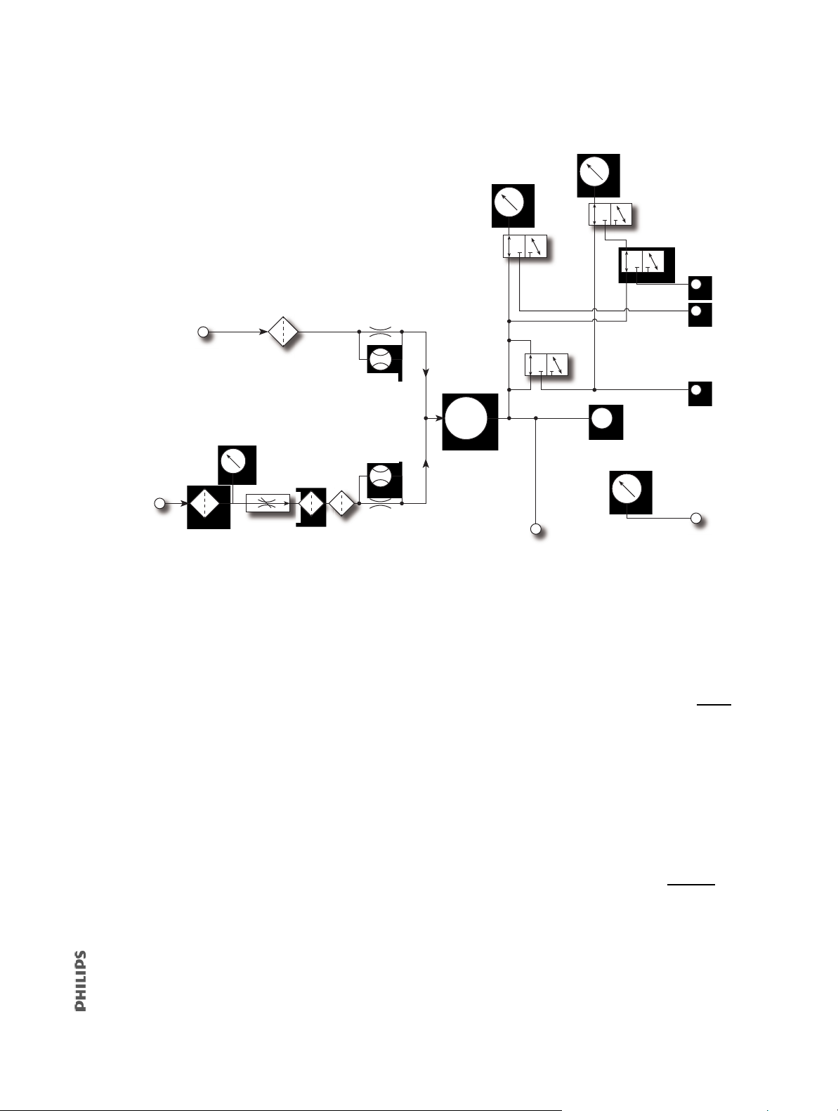
Figure 3-1 shows the ventilator pneumatic schematic.
High pressure
O
2
inlet
276 to 600 kPa /
40 to 87 psi
O
2
inlet
filter
O
2
inlet pressure sensor
Proportional
solenoid valve
Sintered flow
normalizers
Bypass
element
O2 flow
sensor
Mixing air & O
2
Air flow
sensor
Bypass
element
Air inlet filter
Ambient air
inlet
Blower
Internal exhalation port
Patient port
Barometric pressure sensor
Machine pressure sensor
Proximal pressure sensor
Machine
pressure
line
Purge
solenoid
Ambient pressure
Ambient pressure
Ambient pressure
Proximal pressure
SOL1
SOL2
SOL3
SOL4
Air
inlet
Air inlet
filter
Figure 3-1: Ventilator Pneumatic Subsystem Schematic
3.1.1 Air Inlet
Ambient air is entrained through the air inlet.
3.1.2 Air Inlet Filter
The air inlet filter is designed to filter 5-micron
particles at 70% efficiency at 150 SLPM flow.
1049766 T V60/V60 Plus Ventilator Service Manual 39
Page 40

3.1.3 Air Flow Sensor
O2 pressure transducer
Machine pressure
transducer
Proximal pressure
transducer
Barometric pressure
transducer
DA PCBA
Air flow
sensor
Manifold
The air flow sensor measures a subset (bypass
flow) of total flow in the pneumatic air path
and interpolates the measurements according
to constants that are calculated during gas
delivery subsystem (GDS) calibration. The air
flow sensor also helps provide closed-loop
control of gas flow during O
blending.
2
3.1.4 Machine and Proximal Pressure Transducers
The machine and proximal pressure transducers on the DA PCBA measure the machine and
proximal pressure over a range of –20 to +65 cmH
O.
2
3.1.5 Barometric Pressure Transducer
The barometric pressure transducer on the DA PCBA measures barometric pressure over a
range of 525 to 850 mmHg.
3.1.6 O2 Pressure Transducer
The O2 pressure transducer on the DA PCBA can measure accurate inlet pressures over a
range of 0 to 100 psig. An alarm results if O
supply pressure is below 40 psig (276 kPa) or
2
above 92 psig (634 kPa).
40 V60/V60 Plus Ventilator Service Manual 1049766 T
Page 41

3.1.7 Manifold, O2 Inlet Filter, Filter Element
Manifold
O
2
breather
vent (not
replaceable)
O2 filter
element (not
replaceable)
O
2
inlet filter
Manifold
O2 solenoid
valve
Manifold
O2 flow
sensor
BlowerBlower
The manifold includes a connection for the O2 inlet fitting to accommodate country-specific
connections. The manifold provides the pneumatic interfaces to the air inlet, O2 inlet,
O
2
blower inlet, and proximal and machine pressure lines.
The O
inlet filter removes 5-micron particles from the O2 gas supply.
2
A 40-m
40-micron O
icron sintered bronze filter element acts to reduce turbulence in the O2 flow. The
breather vent reduces noise in the O2 flow.
2
3.1.8 O2 Solenoid Valve
The O2 solenoid valve and valve driver circuitry control
the flow of O
solenoid valve is closed when there is a loss of power or
system reset.
according to the set O2 and flow. The O2
2
3.1.9 O2 Flow Sensor
The O2 flow sensor measures a subset (bypass
flow) of the total flow. These measurements are
interpolated according to constants that are
calculated during GDS calibration. Together, the
solenoid valve and flow sensor provide
O
2
closed-loop control for delivered O
flow.
2
3.1.10 Blower
The blower is controlled by the MC PCBA, and generates
flow and pressure for the system. The blower includes an
impeller, housing, and a three-phase brushless DC motor.
The blower delivers a maximum pressure of less than
125 cmH
10,000 to 22,500 revolutions per minute (RPM) in
0 msec from a nominal 5- to 25-cmH
12
Maximum motor speed is approximately 40,000 RPM. The blower motor has internal Hall
ffect sensors that are monitored by the MC PCBA and measure impeller speed.
E
1049766 T V60/V60 Plus Ventilator Service Manual 41
O in a dead-head condition, can accelerate from
2
O pressure rise.
2
Page 42

3.1.11 Solenoid Valves
Manifold
Solenoid
valves (x4)
Solenoid valves
SOL1: Purge solenoid, uses the machine
pressure line to purge the proximal
pressure line.
SOL2 + SOL4: Machine pressure autozero
solenoids.
SOL3 + SOL4: Proximal pressure autozero
solenoids.
SOL4: Connects machine pressure to the
proximal pressure transducer during
autozero.
SOL1
SOL2
SOL3
SOL4
Four solenoid valves are mounted on the manifold and controlled by the DA PCBA. These
three-way autozero solenoids include SOL1 (purge solenoid), SOL2 and SOL4 (machine
pressure autozero solenoids), and SOL3 and SOL4 (proximal pressure autozero solenoids).
NOTE: Autozero occurs during POST. POST occurs when the ventilator powers up in
ventilation mode and then every 15 minutes.
42 V60/V60 Plus Ventilator Service Manual 1049766 T
Page 43

3.2 Electronics
PM PCBA
The electronics system provides software-based control and monitoring, power
management, user input, display, subsystem I/O, external communication, and alarms. The
electronics system includes a microcontroller for control and monitor processing.
Control tasks include breath delivery, patient data calculation, and alarm detection/
esponse. Monitoring tasks include controlling the LCD, front panel keys and indicators,
r
inputs, and primary alarm output. An independent watchdog control provides safety
monitoring.
The electronics system includes:
• Power management (PM) PCBA • Liquid crystal display (LCD)
• Power supply • Backlight inverter PCBA
• Internal battery • Touchscreen assembly
• CPU PCBA • Nav-ring assembly/Accept button
• Motor controller (MC) PCBA • Power switch overlay
• Data acquisition (DA) PCBA •Switch PCBA
•Flow sensors • User interface (UI) PCBA
• User interface
3.2.1 Power Management (PM) PCBA
• Battery charging and management circuitry.
• Internal supply voltages (supply voltages: 3.3 V, 5 V, 12 V, 35 V).
• Fan power and tachometer monitoring.
• Backup alarm control circuitry, including power fail detection.
• Power switch control circuitry.
• System alarm and reset management.
• Electrical interfaces between the CPU PCBA, LCD,
and the
• Includes an EEPROM for programmed data, board
id
hours.
• The battery can become so discharged that it can
o
pr
and f
above the internal circuit cutoff voltage, the battery can then accept the full charging
current of 3.5 A. A seriously-depleted battery may require days of trickle-charging
be
user interface (UI) PCBA.
entification information, and PM PCBA power-on
nly accept a trickle charge of approximately 10 to 100 mA. At this point the battery
ocessor turns on the charger (and fan) every 4 seconds, then turns off the charger
an after 2 seconds if charger current is insufficie
fore it can again accept full charging current.
nt. Once the battery voltage is
1049766 T V60/V60 Plus Ventilator Service Manual 43
Page 44

3.2.2 Power Supply
Internal
battery
Power supply
• Provides ventilator and battery recharging power
from AC line voltage.
• Converts AC line voltage (90 to 264 VAC,
50 to 60 Hz) into 24 VDC power.
• Includes input over-current, output over-voltage,
and output c
urrent-limiting protection.
3.2.3 Internal Battery
• 14.4-V, 11.0-Ah lithium-ion battery has a run-time of
six hours under normal conditions.
• Provides operating power when AC power is not
a
vailable.
• Provides charge and temperature status to the
PM PCBA.
• Internal circuitry monitors battery status, provides self-contained fault control
f
eatures, and communicates this information to the PM PCBA.
• Recharges in approximately 5 hours.
• Replace every 5 years based on the date of manufacture recorded on the battery label
(also v
iewable on the Ventilator Information screen in Diagnostic mode).
NOTE
If the battery becomes discharged to the point that it will only allow a trickle charge
(approximately 10 mA to 100 mA), the battery processor turns on the charger and fan every
4 seconds. After 2 seconds, if the battery processor determines that insufficient charger
current is flowing, it turns off the charger and fan. This process continues until the battery
voltage is charged above the battery internal circuit cutoff voltage, after which the battery
accepts full charging current (3.5 A). It can take days of trickle-charging to charge a
seriously-depleted battery to the point when it can accept full charging current.
44 V60/V60 Plus Ventilator Service Manual 1049766 T
Page 45

3.2.4 CPU PCBA
CPU PCBA
• Microprocessor: once in a run state, the
microprocessor can only be reset by a watchdog
timeout or out-of-specification power condition.
Monitors operation of the ventilator and controls
delivery of air and O
ventilator operation.
• Flash memory: 8 MB program storage.
•RAM: 8 MB for program execution and volatile data
sto
rage.
• EEPROM: 4 KB of storage for board-specific
inf
ormation (including operating hours, time since
last service, serial numbers, part numbers, and software and hardware revisions).
to the patient. Verifies safe
2
• Watchdog timer: disables the blower and O
flow if not strobed by software within a
2
predefined time window that is independent of the CPU master clock. In addition,
ensures that software is operating.
• Real-time clock (RTC): a time of day clock tha
t provides the date and time to the
ventilator, and is powered by a dedicated 3-V lithium coin cell battery.
• LCD interface supports a display of 1024 horizontal x 768 vertical pixels in 256 colors
w
ith a refresh rate of at least 50 Hz. The CPU PCBA controls LCD brightness by varying
ontrol voltage over a range of 0 to 3.5 V (minimum to maximum brightness).
a c
• Touchscreen interface supports a five-wire type touchscreen.
• Nav-ring rotary adjustment interface (if present) with a minimum resolution of 24 ticks
pe
r revolution.
• User key switches: interfaces to front panel keys.
• Alarm subsystem: includes a speaker driver circuit for the two main speakers, a backup
pi
ezo alarm (soldered to the CPU PCBA), and a three-wire relay-controlled remote
alarm interface (normal open, NO, or normal closed, NC) on the ventilator back panel.
Table 3-1 summarizes the characteristics of the remote alarm interface.
• Blower speed monitor measures blower speeds from 3,000 to 50,000 RPM with 2%
acy.
accur
• Electrical interfaces to the power management (PM) and motor controller (MC)
PC
BAs.
• Two USB ports and an Ethernet connection are reserved for future use.
• RS-232 serial connector (female DB-25). C
onnects to hospital information systems and
other serial devices. Tab l e 3 - 2 summarizes hospital information system (HIS) RS-232
port pinout.
1049766 T V60/V60 Plus Ventilator Service Manual 45
Page 46
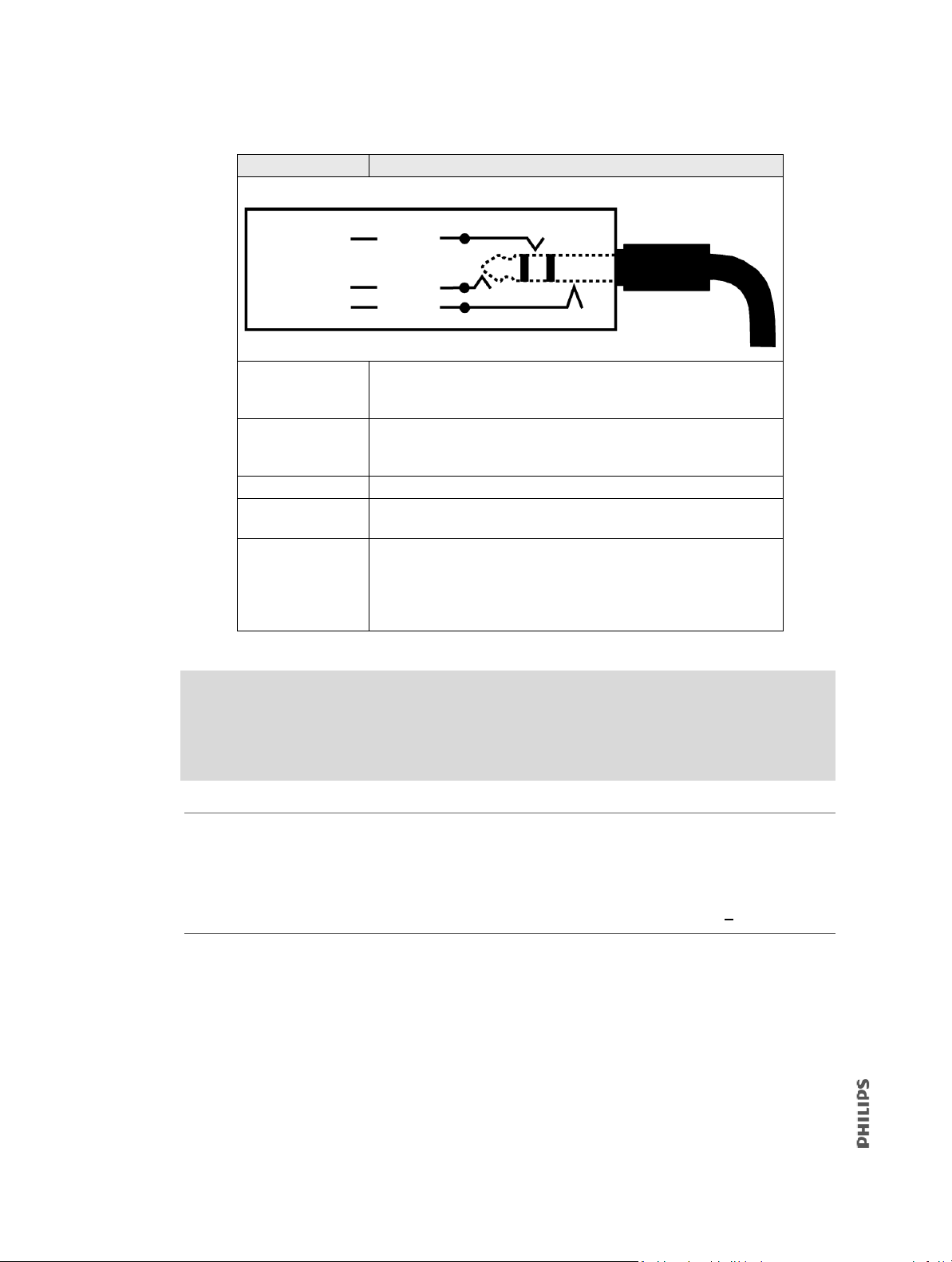
Table 3-1: Remote Alarm Interface
Remote alarm
connector and cable
NO
NC
Common
Sleeve
Tip
Ring
Component Description
NO contact Normally open (NO) relay contact. An open contact indicates that a
high-priority alarm is not active. A closed contact indicates that a high
priority alarm is active.
NC contact Normally closed (NC) relay contact. A closed contact indicates that a
high-priority alarm is not active. An open contact indicates that a high
priority alarm is active.
Common contact Used with both NO and NC protocols.
Remote alarm connector
Remote alarm
description
Standard 1/4-inch female audio (ring, tip, sleeve) connector.
The remote alarm port allows high-priority alarm conditions to be
annunciated away form the ventilator (for example, when the ventilator is in an isolation room). The ventilator sends alarm signal to a
remote alarm through the remote alarm connector at the back of the
ventilator.
WARNING
• To prevent possible patient injury due to nonannunciating alarms, verify the
operation of any remote alarm device before use.
• To ensure the functionality of the remote alarm, connect only Philips-approved
cables to the remote alarm port.
CAUTION
The remote alarm port is intended to connect only to an SELV (safety extra-low voltage) and
ungrounded system with basic insulation to ground, in accordance with IEC 60601-1. To
prevent damage to the remote alarm, make sure the signal input does not exceed the
maximum rating of 24 VAC or 36 VDC at 500 mA with a minimum current of > 1 mA.
NOTE
Selecting Alarm Silence deactivates the remote alarm.
46 V60/V60 Plus Ventilator Service Manual 1049766 T
Page 47
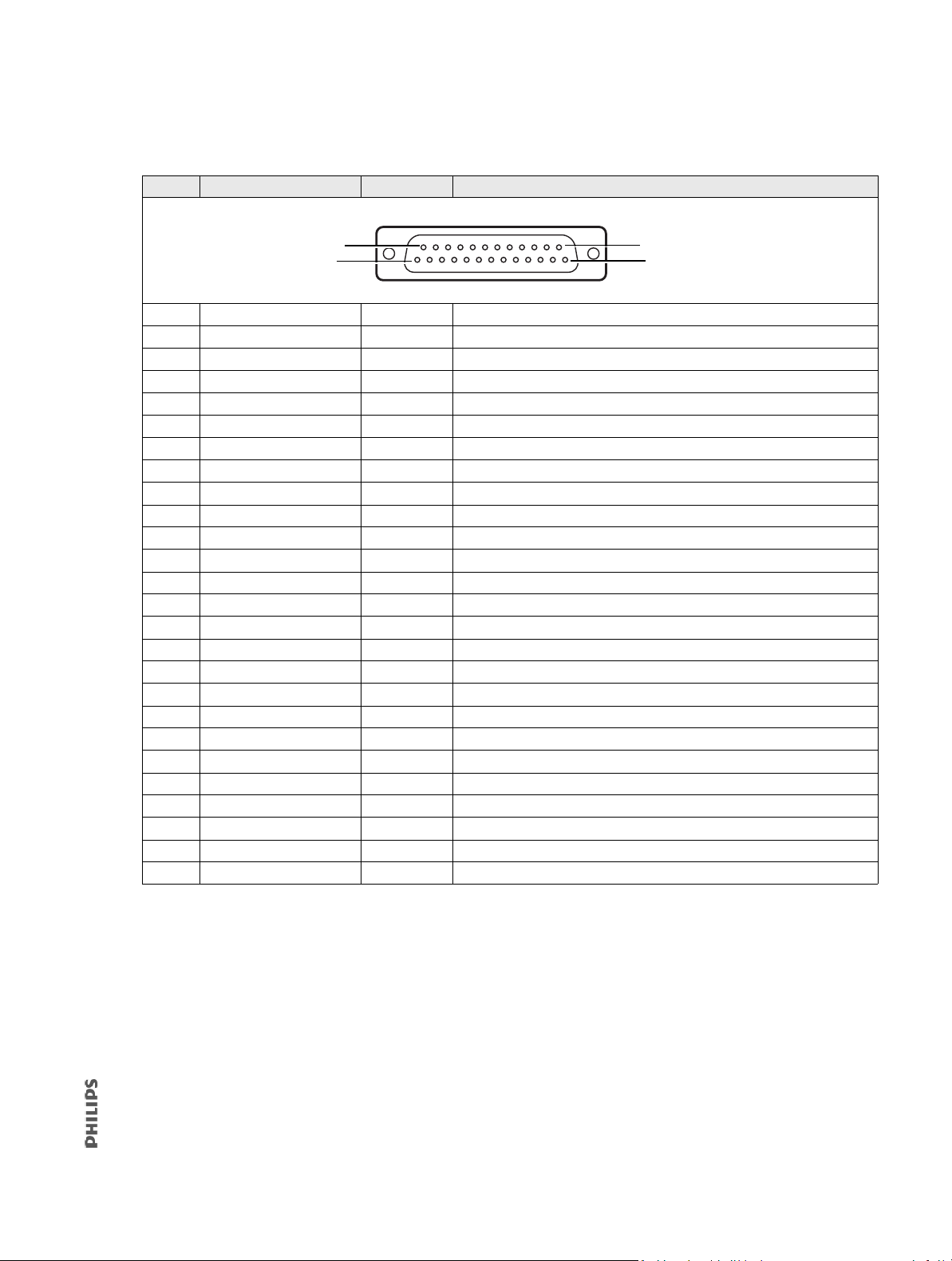
Table 3-2: Ventilator HIS Serial Communications Port Pinout
1
13
25
14
Pin Signal I/O Description
1 HIS_RS232_SHLD Power HIS RS232 cable shield
2 HIS_RS232_TxD Output HIS RS232 transmit data output
3 HIS_RS232_RxD Input HIS RS232 receive data input
4 HIS_RS232_RTS Output HIS RS232 ready to send
5 HIS_RS232_CTS Input HIS RS232 clear to send
6 HIS_RS232_DSR Input HIS RS232 data set ready
7 HIS_SIG_RTN Power HIS RS232 signal common
8 PULSE_OX_IN Input Pulse oximeter analog Input
9 HIS_DIG_IN0 Input HIS digital input #0, 0-3.3 V digital logic level (0-5 V tolerant)
10 HIS_DIG_IN1 Input HIS digital input #1, 0-3.3 V digital logic level (0-5 V tolerant)
11 HIS_ANALOG_IN00 Input HIS analog input #0, 0-5.0 V analog voltage level
12 HIS_ANALOG_IN01 Input HIS analog input #1, 0-5.0 V analog voltage level
13 HIS_SIG_RTN Power HIS RS232 signal common
14 HIS_DIG_IN2 Input HIS digital input #2, 0-3.3 V digital logic level (0-5 V tolerant)
15 HIS_DIG_IN3 Input HIS digital input #3, 0-3.3 V digital logic level (0-5 V tolerant)
16 HIS_DIG_OUT0 Output HIS digital output #0, 0-3.3 V digital logic level
17 HIS_DIG_OUT1 Output HIS digital output #1, 0-3.3 V digital logic level
18 HIS_DIG_OUT2 Output HIS digital output #2, 0-3.3 V digital logic level
19 HIS_DIG_OUT3 Output HIS digital output #3, 0-3.3 V digital logic level
20 HIS_RS232_DTR Output HIS RS232 data terminal ready
21 HIS_SIG_RTN Power HIS RS232 signal common
22 nHIS_BOOT_SEL Input Boot select signal: 0 = download, 1 = flash
23 HIS_ANALOG_OUT0 Output HIS analog output #0, 0-5.00 V analog voltage level
24 HIS_ANALOG_OUT1 Output HIS analog output #1, 0-5.00 V analog voltage level
25 HIS_ANALOG_OUT2 Output HIS analog output #2, 0-5.00 V analog voltage level
SHLD Chassis Power Cable shield
Supported communication protocols
The ventilator supports these communication protocols:
• Philips IntelliBridge (VueLink): Use for connecting to Philips monitors, refer to the
V60/V60 Plus Ventilator Connectivity Guide (
1149120MC).
• Legacy (VRPT/SNDA): Fixed text-based protocol (not to be used for developing new
drive
r interfaces). For this protocol specification, refer to the V60/V60 Plus Developers
Guide: Communications Interface for VRPT/SNDA (1147828MC).
• PVOI (Philips Ventilator Open Interface): Use for interfacing with non-Phillips monitors
r devices. Non-disclosure is required; contact your account manager for more
o
information.
1049766 T V60/V60 Plus Ventilator Service Manual 47
Page 48

3.2.5 Motor Controller (MC) PCBA
DA PCBA
MC PCBA
Speaker assembly
• Controls the blower motor according to speed or
current as commanded by ventilator software.
• Provides electrical interfaces to the DA PCBA, O
and
2
air flow sensors, fan, and primary speaker.
• Includes monitoring of an embedded temperature
se
nsor in the blower motor.
• Includes analog to digital converters (ADCs) and
d
igital to analog converters (DACs) for flow control
and monitoring.
• Includes two energy storage capacitors that increase motor power usage efficiency
and powe
r a backup audible alarm (a piezo alarm) and Alarm LED for at least two
minutes.
• Includes EEPROM for calibration data, board identification information, and MC PCBA
r-on hours.
powe
3.2.6 Data Acquisition (DA) PCBA
• Provides precision measuring and signal conditioning.
• Includes analog-to-digital converters (ADCs) and
di
gital-to-analog converters (DACs) for flow and
pressure monitoring signals.
• Controls the O
• Includes barometric (measurement range 525 to
85
0 mmHg) and O
0 to 100 psig) transducers.
solenoid valve with 12-bit accuracy.
2
pressure (measurement range
2
• Includes individual patient proximal and machine pressure transducers (measurement
r
ange –20 to +65 cmH
2
O).
• Includes EEPROM for calibration data, board identification information, and DA PCBA
powe
r-on hours.
• Drives the solenoid valves mounted to the manifold.
• Interfaces to the air and O
flow sensors.
2
3.2.7 Primary Speakers
• The primary audio alarm includes two alarm speakers in
the base unit (adjustable from 60 to 95 dBA at 1 m), one
onnected through the PM PCBA, and one connected
c
through the MC PCBA.
48 V60/V60 Plus Ventilator Service Manual 1049766 T
Page 49

3.2.8 Flow Sensors
LCD assembly
User interface
O2 flow sensor
Air flow sensor
• Calibrated to the specific gas
(air or O
• Provides the signal source for the O
and air flow signals. Converts
manifold gas flow into an analog
signal, which is sent to DA PCBA for
filtering and conversion.
).
2
2
• Air flow sensor measures flows from -240 to 240 SLPM. O
flow sensor measures flows
2
from 0 to 240 SLPM.
• Includes EEPROM for calibration data, board identification information, and power-on
ho
urs for each flow sensor.
3.2.9 User Interface (UI)
• Includes indicators and controls for setting and
monitoring parameters.
• Includes LCD, backlight inverter PCBA, touchscreen,
powe
r switch overlay, Accept button or rotary
adjustment (nav-ring) assembly, UI PCBA, and switch
BA.
PC
3.2.10 LCD Assembly
• 12.1-in. diagonal flat panel, 768 x 1024 pixels with
6-bit color.
• Connects to backlight inverter PCBA and CPU PCBA
thr
ough the PM PCBA.
• HYDIS LCD: Cold cathode fluorescent lamp (CCFL)
back
light with 10,000-hour minimum life (half initial
brightness).
• NEC LCD: CCFL backlight with 50,000-hour minimum
fe (half initial brightness).
li
1049766 T V60/V60 Plus Ventilator Service Manual 49
Page 50

3.2.11 Backlight Inverter PCBA
Touchscreen assembly
Backlight
inverter
PCBA
Older ventilators:
nav-ring assembly
with Accept button
Newer ventilators:
Accept button
without nav-ring
• Provides an adjustable backlight drive voltage.
• Backlight dimming capability using a 0 to 3.5-V control voltage
fr
om the CPU PCBA through the PM PCBA.
3.2.12 Touchscreen Assembly
• Uses a robust five-wire resistive panel.
• Resolves touches in a configuration 0.3 x 0.3-in.
ma
trix.
3.2.13 Nav-ring Assembly/Accept Button
• All ventilators use touchscreen controls to change setting values and an Accept button
to apply setting values.
• Older ventilators also include a nav-ring, a rotary adjustment is used to change setting
va
lues.
• Newer ventilators include the Accept button only.
• The Accept button contacts the switch PCBA.
50 V60/V60 Plus Ventilator Service Manual 1049766 T
Page 51

3.2.14 Power Switch Overlay
UI PCBA
Power switch overlay
Switch PCBA
• Includes the power switch, and embedded
indicators for power status, battery charge
status, and alarms.
3.2.15 Switch PCBA
• Interconnects between the nav-ring (if present)
and the UI PCBA and CPU PCBA.
• Provides a center push button (the Accept button)
and in
terface to nav-ring (if present).
• Connects to UI PCBA.
3.2.16 UI PCBA
• Provides a connection for backlight PCBA,
touchscreen, switches, and switch PCBA to PM PCBA.
• Mounts behind the LCD and provides connectors to
the
backlight inverter PCBA, power switch overlay,
switch PCBA, and touchscreen.
• Connects to the PM PCBA.
1049766 T V60/V60 Plus Ventilator Service Manual 51
Page 52

3.3 Electronic Signal Paths
Tabl e 3-3 summarizes the electronic signal paths for ventilator components.
Table 3-3: Ventilator Signal Paths
Component Signal Path Sequence
Air flow sensor DA PCBA, MC PCBA, CPU PCBA
Alarm indicator Power switch overlay, UI PCBA, PM PCBA, CPU PCBA
Backlight inverter PCBA Input: UI PCBA, PM PCBA, CPU PCBA
Output: LCD CCFL
Barometric pressure transducer DA PCBA, MC PCBA, CPU PCBA
Battery indicator Power switch overlay, UI PCBA, PM PCBA, CPU PCBA
Blower motor MC PCBA
CPU PCBA DAC CPU PCBA
DA PCBA ADC DA PCBA, MC PCBA, CPU PCBA
DA PCBA DAC DA PCBA, MC PCBA, CPU PCBA
Ethernet connector CPU PCBA
Fan MC PCBA, CPU PCBA, PM PCBA
LCD Power: PM PCBA. Signal: PM PCBA, CPU PCBA.
CCFL: Backlight inverter PCBA
Internal battery PM PCBA
Speaker #1 MC PCBA, CPU PCBA
Speaker #2 PM PCBA, CPU PCBA
MC PCBA ADC MC PCBA, CPU PCBA
MC PCBA DAC MC PCBA, CPU PCBA
Nav-ring assembly/Accept button Switch PCBA, UI PCBA, PM PCBA, CPU PCBA
Remote alarm connector CPU PCBA
flow sensor DA PCBA, MC PCBA, CPU PCBA
O
2
O2 inlet pressure sensor DA PCBA, MC PCBA, CPU PCBA
solenoid valve DA PCBA
O
2
Power indicator Power switch overlay, UI PCBA, PM PCBA, CPU PCBA
Power supply Input: AC inlet. Output: PM PCBA.
Power switch Power Switch Overlay, UI PCBA, PM PCBA, CPU PCBA
Proximal pressure sensor DA PCBA, MC PCBA, CPU PCBA
Solenoid valves DA PCBA
Switch PCBA UI PCBA, PM PCBA, CPU PCBA
Touchscreen UI PCBA, PM PCBA, CPU PCBA
USB device connector CPU PCBA
USB host connector CPU PCBA
52 V60/V60 Plus Ventilator Service Manual 1049766 T
Page 53
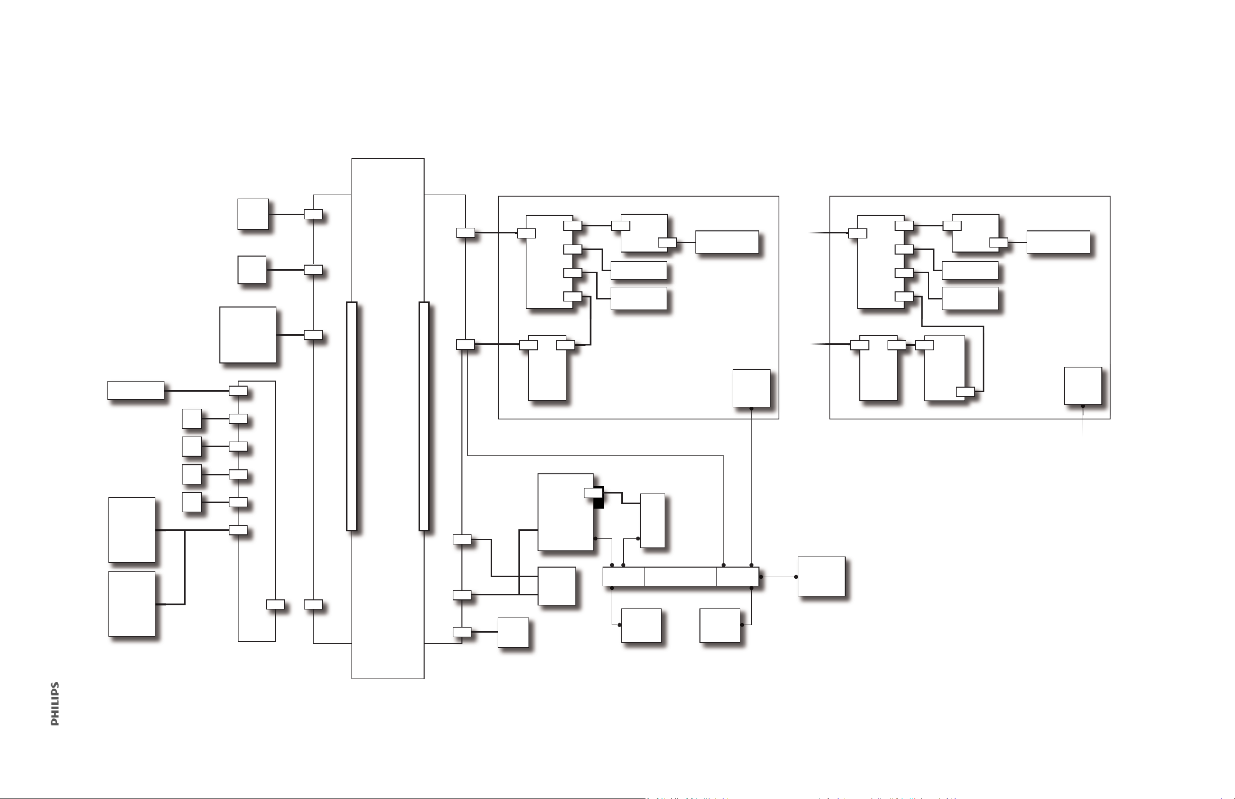
Figure 3-2 shows a wiring diagram for the main assembly.
O2 solenoid
SOL1
SOL2
SOL3
SOL4
Air flow
sensor
O
2
flow
sensor
MC
PCBA
CPU PCBA PM
PCBA
UI
PCBA
Switch
PCBA
Nav-ring
(if present)
Touchscreen
Power switc h
overlay
GUI
chassis
LCD
(NEC)
Backlight
inverter
PCBA
Fan
Speaker
#1
Speaker
#2
Blower
DA
PCBA
GND stud
Power
supply
AC
inlet
Gas outlet
port
Battery
GND flagMain chassis
GDS
manifold
Proximal
pressure
port
User interface subsystem
(NEC LCD)
GUI
chassis
LCD
(HYDIS)
Switch
PCBA
Touchscreen
Power switch
overlay
Nav-ring
(if present)
UI
PCBA
User interface subsystem
(HYDIS LCD)
Figure 3-2: Main Assembly Wiring Diagram
1049766 T V60/V60 Plus Ventilator Service Manual 53
Page 54
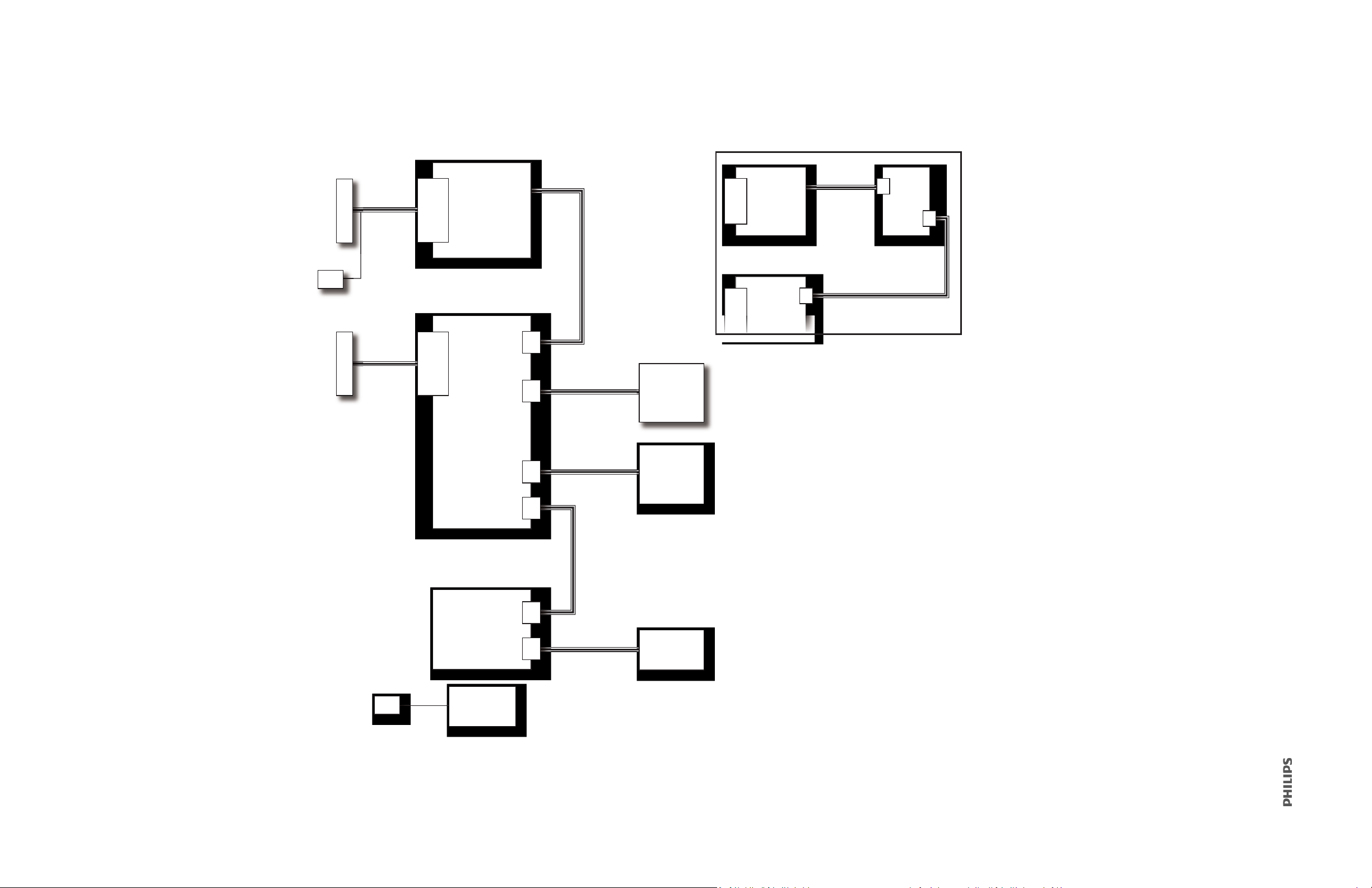
Figure 3-3 shows a wiring diagram for the UI subsystem.
User interface
PCBA
User interface
touchscreen
Power switch
overlay
Switch PCBA
Nav-ring
(if present)
User interface
LCD tray
User interface
LCD (NEC)
Backlight
inverter
PCBA
Gnd
Gnd
Connector to
PM PCBA
Connector to
PM PCBA
User
interface
PCBA
User
interface
LCD
(HYDIS)
Figure 3-3: UI Assembly Wiring Diagram
54 V60/V60 Plus Ventilator Service Manual 1049766 T
Page 55
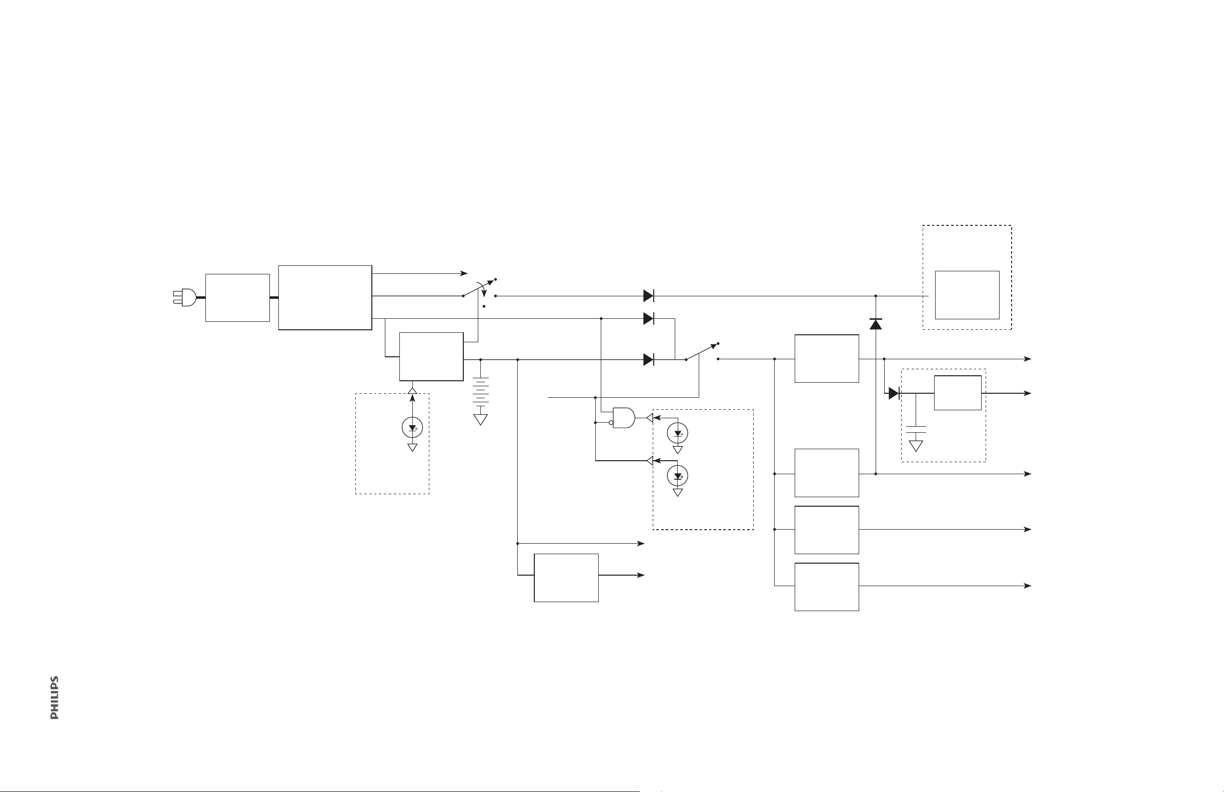
Figure 3-4 shows a block diagram of the ventilator voltages.
Li-ion battery
charger
Power supply
250 W @ 24 V
AC inlet &
line filter
DC-DC
10 V
Linear 3.3 V
Part of UI
subsystem
Yel lo w
battery
LED
78.000 µF
PWR_EN
3.3VAO
V
BATT
Li-ion
14.4 V
Part of UI
subsystem
Green
ON LED
Yellow
AC LED
(12 - 16 V)
(12 - 16 V)
V
MAIN
(12 - 24 V)
Part of enclosure
subsystem
Part of GDS
V
BACKUP
35V
5VCC
33VDD
DC-DC
35 V
DC-DC
12 V
DC-DC
5 V
DC-DC
3.3 V
12V
12-V fan
Figure 3-4: Ventilator Voltages Block Diagram
1049766 T V60/V60 Plus Ventilator Service Manual 55
Page 56
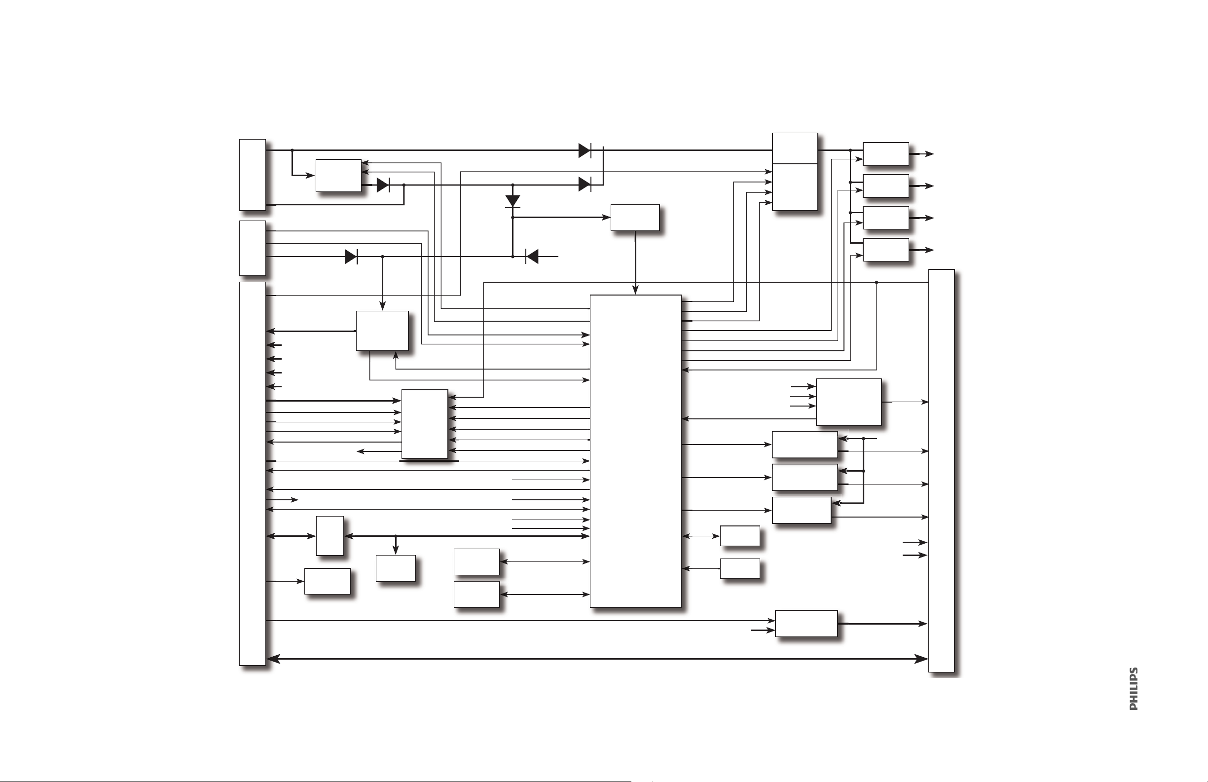
Figure 3-5 shows a block diagram of the PM PCBA.
Power
connector 1
Power
connector 2
CPU PCBA
connector
User
interface
connector
Battery
charger
Fan driver/
monitor
Backup
alarm
control
logic
3.3V
VREG
Power
switch
Control
logic
DC-DC
3.3V
DC-DC
5V
DC-DC
12V
DC-DC
35V
Alarm LED
driver
Batt charge
LED driver
AC
LED driver
ON
LED driver
EEPROM
Analog
VREF
CCFL power
switch
Power
management
microcontroller
Primary
speaker
connector
LVD S
interface
ADDR
decode
Mfg & test
EEPROM
In-circuit
debug
connector
RS-232 serial
connector
+24V
OLS
+35V
SMBus clock
SMBus data
V
BATT
power bus
V
MAIN
V
OLS
power bus
+12V
OLS
+12V
+12V
C
power bus
SPI bus
Feed-through connections
FAN _E NAB LE
V
AO
+12V
5VCC
33VDD
DISABLE_PWR_SPLY_0
35V_CLOCK
DISABLE_PWR_SPLY_1
ENABLE_PWR_SPLY
12V_CLOCK
5V_CLOCK
3.3V_CLOCK
+35V
+12V
5VCC
33VDD
5VCC
33VDD
+12V
C
LCD_BKLT_EN
+12V
bnBACKUPALARM
LED_ALARM
nWD_CPU
bBKUP_ALARM_STB
BKUP_ALARM_REQ
VBACKUP power bus
I_FAN (analog)
ARM_BACKUPALARM
DISABLE_BACKUPALARM
BACKUPALARM_STRB
nWD_PMC
FAN_ TACH
PROC_PWR_FAULT
VBACKUP POWER BUS
BATT_CHRG_ENABLE
BATT_CHRG_CLOCK
DISABLE_BACKUPALARM
bLED_ALARM
33VDD (analog)
+12V
OLS
(analog)
V
BATT
(analog)
+24V
OLS
(analog)
nPOR
bLED_ALARM
AC_ENABLE
bqENABLE_VENT
SW_12V
LED_ALARM
V
LED
(analog)
BATT_LED_ENABLE
ON_ENABLE
Figure 3-5: Power Management (PM) PCBA Block Diagram
56 V60/V60 Plus Ventilator Service Manual 1049766 T
Page 57
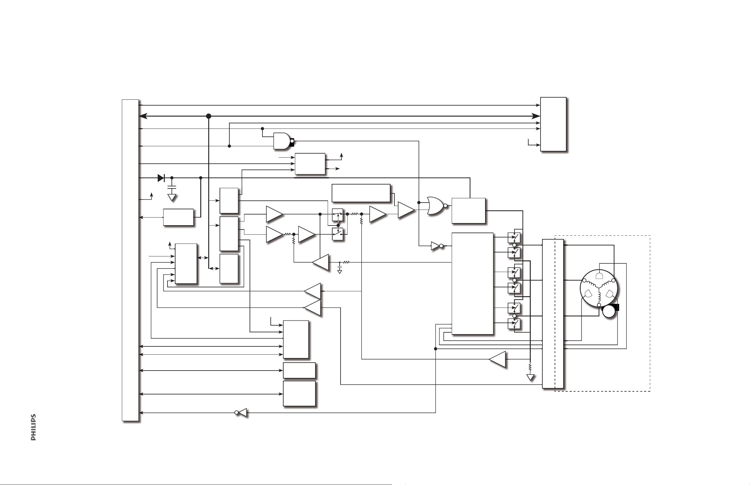
Figure 3-6 shows a block diagram of the MC PCBA.
bO2ON
SPI interface
nSYSTEM_RST_OUT
12V
35V
3.3V, 5V
Energy
storage
bBLOWER_ON
VBKP
regulator
ADC
DA PCBA connector
VBKUP
Power supply
monitors
OVP sense
CAPNO_DIG_IN/OUT
3.3V, 5V, 12V_OVP
nMOTOR_EN
Latch
DAC
EEPROM
3.3V/12V
OVP
3.3V
OVP test
12V_OVP
Current
OVP sense
CAPNO_TxD/RxD
FAN_PWR/TACH
PRI_SPKR
MOTOR_SPEED_SENSE
Speed
MOTOR_REG
Tem p
Motor
controller
Hall Effect
sensor inputs
Ta ch
Enable
Vmotor
regulator
V_MOTOR
Options
connector
Motor speed feedback
Current/speed mode select
A
A
A
A
A
A
A
A
C
120-140-KHz triangle
wave generator
Fan
connector
Primary
speaker
connector
Motor current feedback
Motor temperature
Motor connector
Brushless
DC motor
CPU PCBA connector
3.3V, 5V, 12V_OVP
1049766 T V60/V60 Plus Ventilator Service Manual 57
Figure 3-6: Motor Controller (MC) PCBA Block Diagram
Page 58

58 V60/V60 Plus Ventilator Service Manual 1049766 T
Page 59

4
Ventilator Installation
4.1 Assembly and Installation ....................................................................................60
4.2 Record Ventilator Information .............................................................................61
4.3 Electrical Safety ...................................................................................................62
4.4 Preoperational Check ...........................................................................................62
4.5 Preparing the Ventilator for Use ..........................................................................64
4.6 Electrical Safety/Preoperational Check Form ........................................................65
1049766 T V60/V60 Plus Ventilator Service Manual 59
Page 60

This section outlines the steps required to install and test the V60/V60 Plus ventilator. Use
the form at the end of the section to record all data.
NOTE
It is not required that Philips install the ventilat
additional cost.
or, but this option may be available at an
4.1 Assembly and Installation
Assemble and install all items according to the IFU included with each accessory and as
shown in the ventilator user manual.
The ventilator charges the battery whenever the ventilator is connected to AC power, with
or w
ithout the ventilator switched on. The Battery (charged) LED flashes to show that the
battery is charging. Check the battery charge level before putting a patient on the ventilator
and before unplugging the ventilator for transport or other purposes. The power source
symbol at the bottom-right corner of the screen shows the power source in use and, if the
ventilator is running on battery, the level of battery charge.
60 V60/V60 Plus Ventilator Service Manual 1049766 T
Page 61
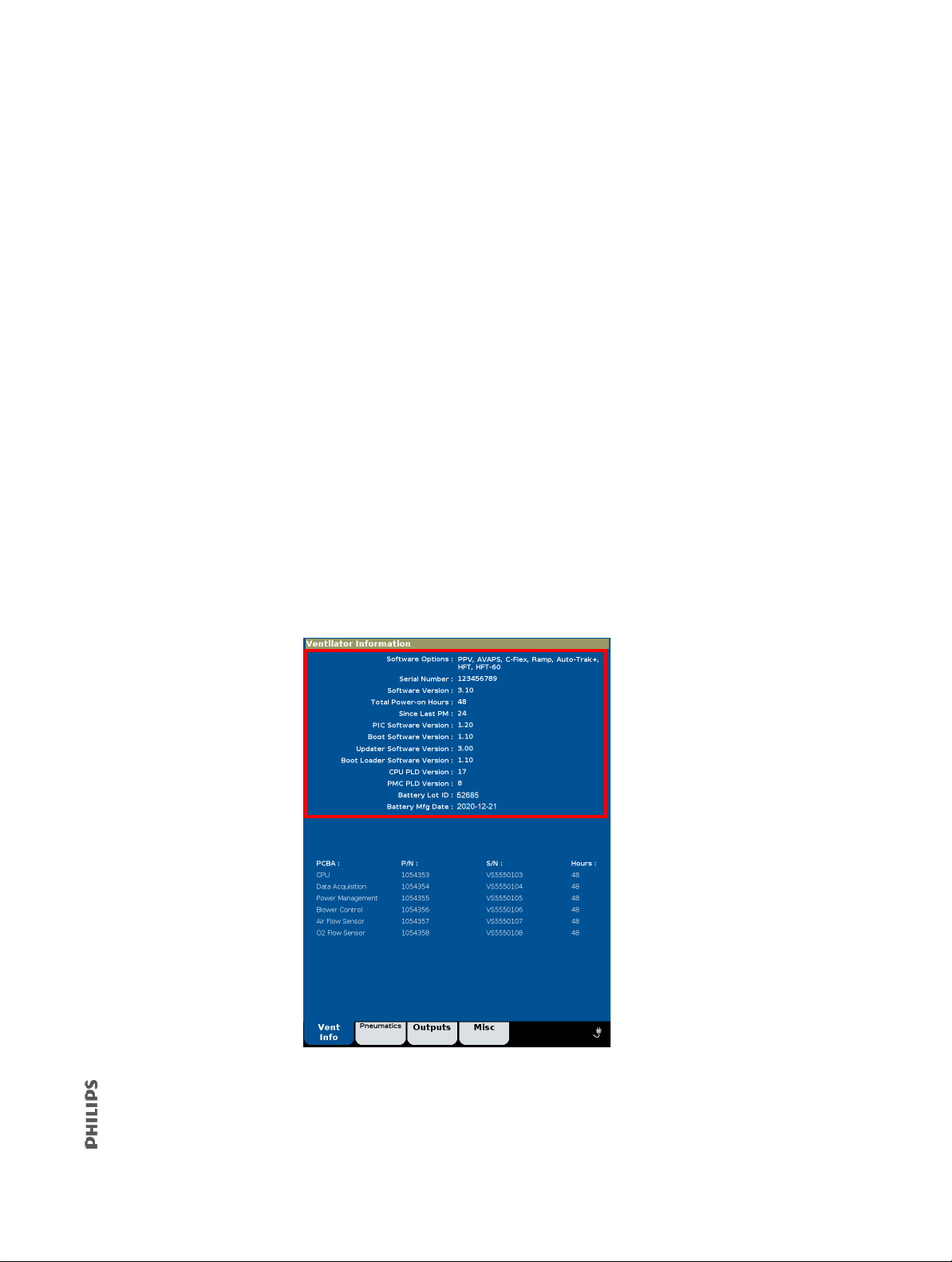
4.2 Record Ventilator Information
1. Connect the ventilator to AC power.
2. If the ventilator is not already in Diagnostic mode, press and hold the Accept button,
and press the On/Shutdown button on the user interface. Within 5 seconds of the
power up, release and press the Accept button again to enter the Diagnostic menu.
3. Touch Service to display the Ventilator Information screen and record the following
information on the Electrical Safety/Preoperational Check Data Form (section 4.6):
• Software options
• Ventilator serial number
•Software version
• Total power-on hours
• Since last PM hours
• PIC software version
•CPU PLD version
•PMC PLD version
•Battery lot ID
•Battery mfg date
4. Turn the ventilator off.
1049766 T V60/V60 Plus Ventilator Service Manual 61
Page 62

4.3 Electrical Safety
Perform the electrical safety test as described in section 9.4.
4.4 Preoperational Check
Required equipment (section 1.2):
Patient circuit (P/N 989805609611 or
989805621321 or 989805621311)
Test lung, 1-L (P/N 989805611871 or
equivalent)
1. Connect the ventilator to AC power.
2
. Connect an oxygen supply to the ventilator.
3. Connect the breathing circuit to the ventilator (see the ventilator user manual for
circuit setup).
4. Attach the test lung to the end of the breathing circuit.
5. Press the On/Shutdown button to start the ventilator in normal ventilation mode.
6. Verify that both the backup alarm (high pitch) and the primary alarm (lower tone)
sound momentarily during start up.
7. Verify the active mask and exhalation port in the Messages window is set to Other. If
not see Selecting the Mask and Exhalation Port instructions in the User Manual. The
window should display this information before proceeding:
Mask: Other, Exh Port: Other
Use Menu to change
8. Select these ventilator settings and alarm limits, reset any alarms if necessary:
Ventilator settings Alarm limits
Mode: S/T High Rate: 90 BPM
IPAP: 10 cmH
EPAP: 6 cmH
Rate: 4 BPM Lo V
I-Time: 1.00 secs HIP: 50 cmH
Rise: 1 LIP: Off cmH
Ramp: Off Lo V
O
: 21% LIP T: 20 secs
2
O Lo Rate: 1 BPM
2
O Hi VT: 1500 mL
2
: Off mL
T
: Off L/min
E
O
2
O
2
9. Verify that the test lung expands during inspiration, collapses during exhalation, and
there is a continuous flow of gas from the exhalation port.
62 V60/V60 Plus Ventilator Service Manual 1049766 T
Page 63

10. Disconnect the proximal line from the ventilator, verify that a Proximal Pressure Line
Disconnect alarm is activated with the following results:
• Audible alarm sounds
• Alarm message appears
• Alarm LED flashes
11. Reconnect the proximal line from the ventilator and verify that the audible alarm is
automatically silenced.
12. Press the Alarm Reset button on the touchscreen to clear the alarm messages.
Go to step 16 if no internal battery is installed.
13. Disconnect the ventilator from AC power and verify the following:
• Ventilator switches to internal battery
• Running on Internal Battery appears in the Alarm window
• Battery in use icon appears
• ON/Shutdown LED remains green
• Audible alarm sounds approximately every 30 seconds
14. Reconnect the ventilator to AC power and verify that the ventilator operation is
uninterrupted, the AC icon is displayed and the Battery In Use icon turns off.
15. Verify that the Battery LED is on or flashing:
• On = battery charge state is 90% to 100%,
• Flashing = battery is being charged
16. Turn the ventilator off.
The preoperational check is complete.
1049766 T V60/V60 Plus Ventilator Service Manual 63
Page 64

4.5 Preparing the Ventilator for Use
Electrical
safety label
PM label
1. Remove all test equipment, tools and materials from the ventilator.
2. If the ventilator is not already in diagnostic mode, press and hold the Accept button,
and press the On/Shutdown button on the user interface. Within 5 seconds of the
power-up, release and press the Accept button again to enter the Diagnostic menu.
3. Touch System Settings, and then touch Restore Default Settings.
4. Touch Date/Time and verify that the date and time are correct, if not set
appropriately.
5. Turn ventilator off.
6. Enter the required information on the electrical safety and PM labels.
7. Affix the labels to the ventilator, and apply a chemical-resistant label over the
electrical safety and PM labels.
NOTE
For software-only updates, do not install the new electrical safety and PM labels.
Installation is complete.
64 V60/V60 Plus Ventilator Service Manual 1049766 T
Page 65
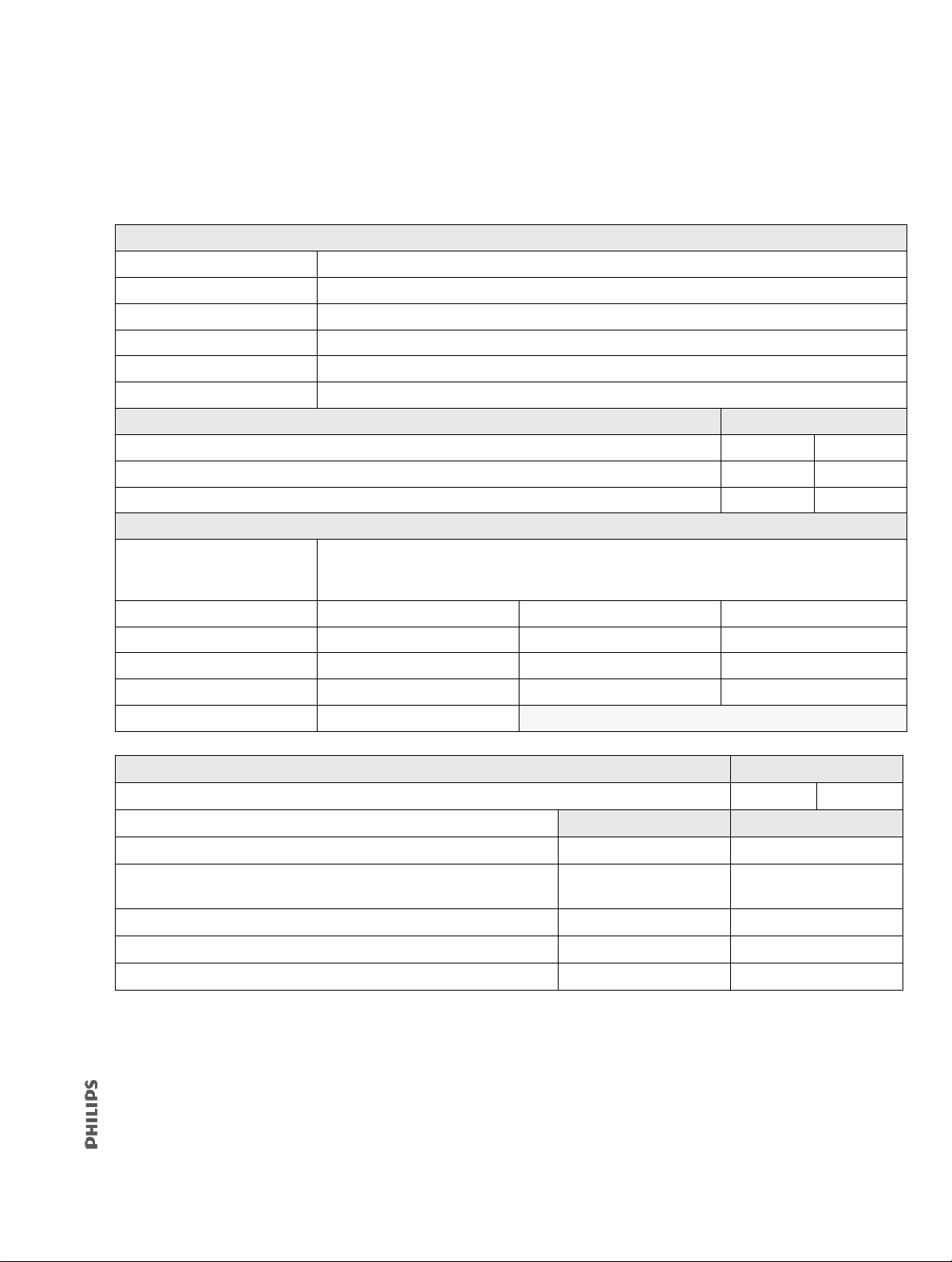
4.6 Electrical Safety/Preoperational Check Form
Complete this form for every ventilator installation or software-only update. Retain this
form for your service records.
Customer information
Facility name:
Contact name:
Address:
City/State/Zip
Phone:
Email:
Preliminary ventilator cleaning and inspection Circle one
Cleaned ventilator exterior? YES NO
Inspected cooling fan filter? YES NO
Inspected air inlet filter? YES NO
Ventilator information
Installed options
(circle all that apply):
Serial number: CPU PLD version:
Software version: PMC PLD version:
Total power-on hours: Battery lot ID:
Hours since last PM: Battery mfg date:
PIC software version:
PPV AVAPS C-Flex RAMP Auto-Trak+ HFT
Other: ________________________________________________________________________
Electrical safety (section 9.4) Circle one
Verify cooling fan operation? PASS FAIL
Resistance and leakage current
Proximal pressure port GND resistance ≤ 200 mΩ mΩ mΩ
Gas outlet port GND resistance
≤ 200 mΩ mΩ mΩ
O
fitting retainer screw GND resistance ≤ 200 mΩ mΩ mΩ
2
Forward leakage current ≤ 280 μA μA μA
Reverse leakage current ≤ 280 μA μA μA
1049766 T V60/V60 Plus Ventilator Service Manual 65
Pass value Fail value
Page 66
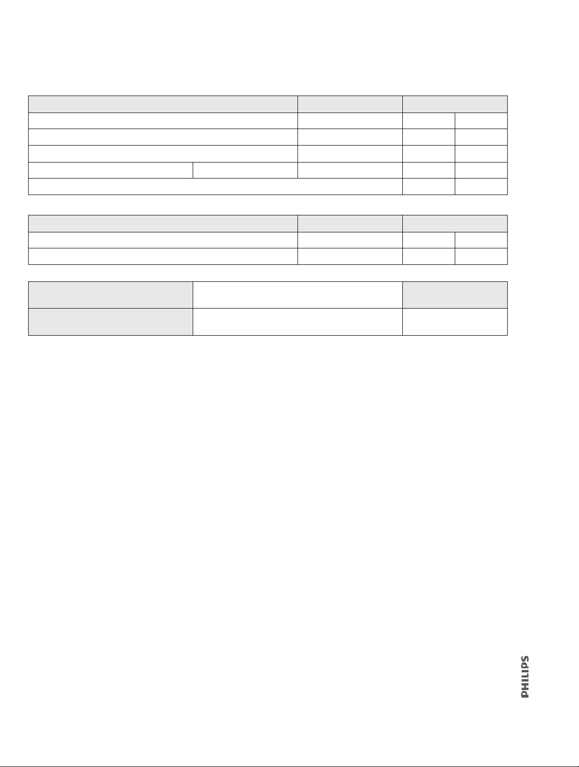
Preoperational check (section 4.4) Steps Circle one
Audible alarms 6 PASS FAIL
Inspiration/exhalation 9 PASS FAIL
Proximal pressure line disconnect 10 - 11 PASS FAIL
Internal battery (circle N/A if not installed) N/A 13 - 15 PASS FAIL
Did the electrical safety/preoperational check pass? PASS FAIL
Preparing the ventilator for use (section 4.5) Steps Circle one
Restore default settings 3 YES NO
Correct date/time 4 YES NO
Technician name (print):
Technician signature:
Date:
66 V60/V60 Plus Ventilator Service Manual 1049766 T
Page 67

5
Maintenance
5.1 Exterior and Touchscreen Cleaning .......................................................................70
5.1.1 Approved Cleaning Agents ......................................................................... 70
5.1.2 Cleaning Instructions .................................................................................. 70
5.2 Exterior and Touchscreen Disinfection .................................................................71
5.2.1 Approved Disinfecting Agents .................................................................... 71
5.2.2 Disinfecting Instructions ............................................................................. 71
5.3 Annual Preventive Maintenance Instructions .......................................................72
5.4 Storage ................................................................................................................75
5.5 Repacking and Shipping .......................................................................................75
5.6 Disposal ...............................................................................................................76
5.6.1 Transferring the Product to Another Owner .............................................. 76
5.6.2 Final Disposal of the Product ..................................................................... 76
1049766 T V60/V60 Plus Ventilator Service Manual 67
Page 68

WARNING
• To reduce the risk of electric shock, power down the ventilator and disconnect it
from AC power before cleaning, disinfecting, or servicing it.
• This product consists of devices that may contain mercury, which must be recycled
or disposed of in accordance with local, state, or federal laws. (Within this system,
the backlight lamps in the monitor display contain mercury.)
NOTE
• It is the user’s responsibility to comply with the information provided in this section.
• Cleaning, disinfection and sterilization are most effective if soiling is not allowed to dry on
a medical device.
• Disinfection and sterilization are most effective on medical devices that were previously
cleaned.
• For all ventilator hardware accessories recommended by Philips, follow the cleaning and
disinfection guidelines described in this section. For multi-patient interfaces and circuit
accessories, consult the product instructions for use. For single patient use accessories, no
cleaning and disinfection is needed.
To ensure the safety and reliability of the ventilator, follow these maintenance procedures
along with ins
titutional policies for cleaning, disinfecting, and maintaining equipment.
The expected life of the V60/V60 Plus ventilator is 10 years. Ventilators in use beyond the
e
xpected service life may require more frequent maintenance and/or repair to maintain
basic safety and essential performance.
Perform cleaning, sterilizing, and preventive maintenance procedures (summarized in Ta bl e
5-1) to ensure consistent ventilator operation. Hospital personnel can perform all
maintenance tasks except the annual preventive maintenance procedures (the preventive
tenance procedures must be performed by a qualified service technician). The
main
ventilator user manual also describes preventive care and maintenance procedures.
68 V60/V60 Plus Ventilator Service Manual 1049766 T
Page 69

Table 5-1: Maintenance Schedule
Frequency Component Maintenance
Every month Air inlet filter Inspect and replace if needed.
Cooling fan filter Inspect for occlusions, dust, lint, or damage. If the filter is
discolored or dirty, wash or rinse thoroughly, then allow the
filter to dry completely before reinstalling.
NOTE
Some environments may require more frequent filter replacement.
Every year
(authorized service
personnel only)
Every 5 years Backup battery Replace the battery.
CAUTION
Only qualified service technicians are to install preventive maintenance kits or perform service procedures.
Ventilator • Install the annual preventive maintenance kit.
• Clean ventilator interior and exterior.
•Inspect the O
• Perform the air and O2 flow sensor zero calibration.
• Complete performance verification procedure.
• Philips recommends updating the operational software to
the current version during this service.
Battery replacement is based on the date of manufacture. The
date of manufacture is on the battery label and in Diagnostic
mode on the Ventilator Information screen.
The lithium ion battery cannot be recycled. Please contact
customer service for safe disposal instructions.
inlet filter.
2
Dispose of all parts removed from the device according to your institution’s protocol. Follow
all local, state, and federal regulations with respect to environmental protection, especially
when disposing of the electronic device or parts of it (for example, oxygen cell, batteries).
Dispose of this device in accordance with l
ocal collections and recycling regulations. For
more information, visit www.philips.com/recycling.
1049766 T V60/V60 Plus Ventilator Service Manual 69
Page 70

5.1 Exterior and Touchscreen Cleaning
CAUTION
• To prevent possible damage to the ventilator, use only those cleaning and
disinfecting agents listed in this manual.
• To prevent possible damage to the ventilator, do not drip or spray any liquids
ectly onto any surface including the front panel, touchscreen, and nav-ring (if
dir
present).
• Never clean or disinfect the touchscreen with an abrasive brush or device, since
his will cause irreparable damage.
t
• Do not attempt to sterilize or autoclave the ventilator.
• Use of non-approved cleaning and disinfecting agents may cause damage to the
enclosure, touchscreen, or parts of the ventilator.
5.1.1 Approved Cleaning Agents
The following cleaning agent is acceptable for use on the touchscreen and exterior surfaces
of the ventilator:
• Soapy water with Medivators Intercept detergent, per manufacturer's recommendation at 1/3 oz (10 mL) per gallon of warm tap water. (Benzalkonium chloride 4.8%,
ethylene glycol monoethyl ether 4.8%, lactic acid 1.4%, alkyl polyglycoside 1.4%)
di
5.1.2 Cleaning Instructions
1. Verify that the ventilator is off and disconnected from AC power.
2. Apply cleaning agent to a soft lint-free cloth or use a disposable wipe. The cloth or
wipe should be saturated but not dripping.
3. Wipe cleaning agent over the entire exterior surface and touchscreen of the
ventilator.
4. Continue wiping until all visible contaminants and soiling are removed.
5. Rinse with a clean, water-dampened cloth and let dry completely before reuse.
70 V60/V60 Plus Ventilator Service Manual 1049766 T
Page 71

5.2 Exterior and Touchscreen Disinfection
CAUTION
• To prevent possible damage to the ventilator, use only those cleaning and
disinfecting agents listed in this manual.
• To prevent possible damage to the ventilator, do not drip or spray any liquids
ectly onto any surface including the front panel, touchscreen, nav-ring (if
dir
present), and Accept button.
• Never clean or disinfect the touchscreen with an abrasive brush or device, since
his will cause irreparable damage.
t
• Do not attempt to sterilize or autoclave the ventilator.
• Use of non-approved cleaning and disinfecting agents may cause damage to the
enclosure, touchscreen, or parts of the ventilator.
5.2.1 Approved Disinfecting Agents
The following disinfecting agents are acceptable for use on the touchscreen and exterior
surfaces of the ventilator:
Disinfectant
Solution of 1 part 5% sodium hypochlorite (bleach) diluted in 9 parts deionized water.
3% hydrogen peroxide
5.2.2 Disinfecting Instructions
1. Verify that the ventilator is off and disconnected from AC power.
2. Ensure that ventilator and touchscreen are clean (section 5.1).
3. Apply cleaning agent to a soft lint-free cloth or use a disposable wipe. The cloth or
wipe should be saturated but not dripping.
4. Wipe disinfecting agent over the entire exterior surface of the ventilator.
5. Let the disinfectant remain on the surface for the following contact times:
• Bleach solution: 2 minutes
• Hydrogen peroxide: 15 minutes
6. Rinse with a clean cloth dampened with water and let dry completely before reuse.
1049766 T V60/V60 Plus Ventilator Service Manual 71
Page 72

5.3 Annual Preventive Maintenance Instructions
Follow these steps to perform the annual preventive maintenance (PM) procedure on
the ventilator.
NOTE
• The annual PM procedure must be performed by a qualified service technician in an
appropriate setting, such as a biomedical repair facility. Use a clean patient circuit and
filters when performing any testing or operational checkout.
• Philips recommends that the operational software be updated to the current version
during the annual preventive maintenance.
1. Verify that the ventilator is off and disconnected from AC power.
2. Clean the exterior of the ventilator using universal precautions (including mask,
gloves, eye protection) by following the instructions in section 5.1, and disinfect as
needed using the instructions in section 5.2.
3. Verify that the ventilator is connected to an AC mains outlet.
4. Enter Diagnostic mode by pressing and holding the Accept button and turn on the
ventilator by pressing the On/Shutdown button on the user interface. Within
5 seconds, press the Accept button again to enter Diagnostic mode. The Diagnostics
Menu appears.
72 V60/V60 Plus Ventilator Service Manual 1049766 T
Page 73
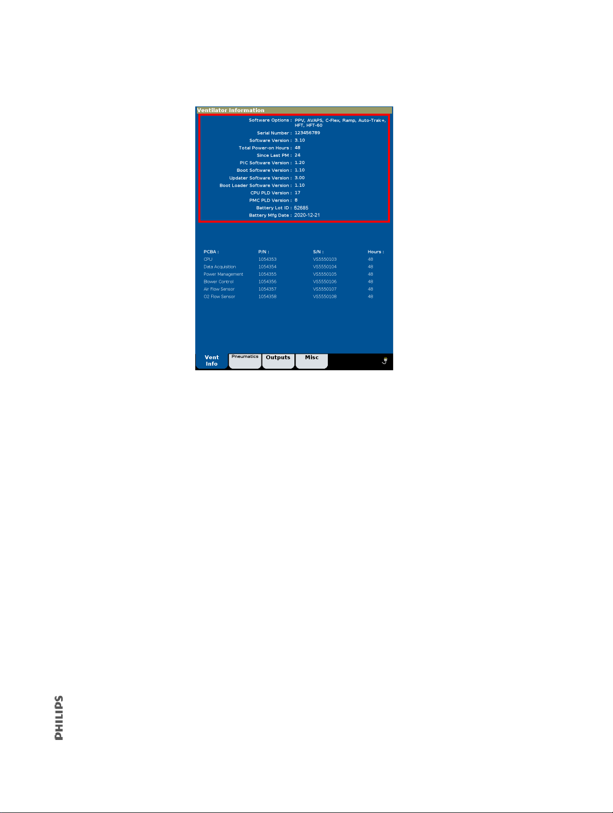
5. Touch Service to display the Ventilator Information screen.
6. Record information on the Performance Verification Data Form (section 9.20):
• Software options
• Ventilator serial number
•Software version
• Total power-on hours
•Hours since last PM
• PIC software version
•CPU PLD version
•PMC PLD version
•Battery lot ID
•Battery mfg date
7. Generate a diagnostic report (DRPTA) for the ventilator (section 7.2).
8. Turn off the ventilator by pressing the On/Shutdown button.
9. Disconnect all power, remove the top cover, and remove the EMI shroud from the
power supply (section 8.18).
10. Use an electrostatic discharge (ESD) safe vacuum to remove any accumulated dust
and debris from the inside the ventilator enclosure.
11. Inspect all electrical and pneumatic connections.
12. Replace the air inlet filter (section 8.2).
13. Remove the O
filter cap from the GDS (section 8.24), inspect the O2 inlet filter for
2
contamination or debris, and verify that it is properly installed.
1049766 T V60/V60 Plus Ventilator Service Manual 73
Page 74

14. From outside the bottom enclosure, use a small screwdriver to remove the filter
Filter retainer
Cooling fan filter
retainer, then replace the cooling fan filter.
15. Reassemble the ventilator.
16. Complete the performance verification (section 9).
17. If the ventilator is not already in diagnostic mode, press and hold the Accept button
and turn on the ventilator by pressing the On/Shutdown button on the user interface.
Within 5 seconds, release and press the Accept button again to enter Diagnostic
mode.
18. Connect the 25-pin to 9-pin HIS/EMR null modem cable between the PC serial port
and the ventilator.
19. Launch Tera Term to enable communication with the ventilator.
20. Type: #RESETPM (all caps) in the dialog box, and press Enter to reset hours since last
PM to zero.
When the hours since last PM have been successfully reset, the dialog box displays:
?RESETPMOK
21. Type #CLRLOG (all caps) in the dialog box, and press Enter to clear the diagnostic log.
When the diagnostic log has been successfully cleared, the dialog box displays:
?CLRLOGOK
74 V60/V60 Plus Ventilator Service Manual 1049766 T
Page 75

22. Select System Settings, and then Restore Default Settings.
Electrical
safety label
PM label
23. Select Date/Time and correct the date and time if necessary.
24. Turn the ventilator off by pressing the On/Shutdown button.
25. Upon successful completion of the performance verification, hours reset, and
restoring the default settings, enter the required information on the PM and electrical
safety labels.
26. Affix the labels to the ventilator.
27. Apply a clear chemical-resistant label over the electrical safety and PM labels.
The annual PM is complete.
5.4 Storage
For ventilator storage requirements, see environmental specifications (section B.9).
5.5 Repacking and Shipping
CAUTION
To prevent possible damage to the ventilator, always ship it with the original packing
material. If the original material is not available, contact Philips to order replacements.
NOTE
Transport of lithium ion batteries is strictly c
Do not ship the battery either in the ventilator or separately.
Remove the battery from the ventilator before shipping the ventilator. Ship the ventilator in
appropriate packaging.
If necessary, Philips will send you a battery return kit (order number 989805663471,
part number 1146145) that contains a prepaid postal label and instructions for returning
he battery for failure analysis if it has failed within 5 years of its manufacture date.
t
ontrolled by international regulations and laws.
1049766 T V60/V60 Plus Ventilator Service Manual 75
Page 76

5.6 Disposal
NOTE
Dispose of the product battery according to all applicable regulations.
Philips is concerned with environmental protection and ensuring safe and effective use of
his product, through proper support, maintenance, and training.
t
Therefore Philips products are designed and manufactured to comply with relevant
guide
lines for environmental protection. As long as the product is properly operated and
maintained, it presents no environmental risks. However, if the product is disposed of
incorrectly, its material could be harmful to the environment. This material is essential to
the product performance and to compliance with statutory and other requirements.
The ventilator complies with the waste electrical and electronic equipment (WEEE) recycling
ective, as evidenced by this mark on the device. Waste electrical and electronic
dir
equipment must not be disposed of as unsorted municipal waste. It must be collected
separately, and it must be disposed of as per local regulations. For information on
decommissioning your equipment, contact your Philips representative.
5.6.1 Transferring the Product to Another Owner
If transferring this product to another owner, the transfer must be complete and include all
product support documentation. Make the new owner aware of the support services that
Philips provides for installing, commissioning, and maintaining the product.
Transferring ownership of medical electrical products can create serious technical, medical,
legal (for example, privacy) risks. Such risks can arise even if the product is given away.
and
Contact Philips before transferring ownership of any product.
After transferring the product to a new owner, communicate any safety-related information,
h as bulletins and field change orders, to the new owner. If you are not able or prepared
suc
to do so, inform Philips so that the new owner receives safety-related information.
5.6.2 Final Disposal of the Product
Contact applicable agencies for advice and information regarding:
• Using competent disposal companies to recycle useful materials.
• Safe and effective disposal of the product.
76 V60/V60 Plus Ventilator Service Manual 1049766 T
Page 77

6
Diagnostic Mode and Troubleshooting
6.1 System Settings ...................................................................................................79
6.1.1 Selecting a Language ..................................................................................80
6.1.2 Setting Date and Time ................................................................................ 82
6.1.3 Restoring Default Settings .......................................................................... 83
6.1.4 Selecting Pressure Units ............................................................................. 84
6.1.5 Enabling Software Options .........................................................................85
6.1.6 Baud Rate ...................................................................................................86
6.1.7 Alarm Volume Escalation ...........................................................................87
6.2 Service .................................................................................................................88
6.2.1 Viewing Ventilator Information ..................................................................88
6.2.2 Pneumatic Controls .................................................................................... 89
6.2.3 Output Controls ......................................................................................... 91
6.2.4 Miscellaneous ............................................................................................ 92
6.3 Touchscreen Calibration .......................................................................................96
6.4 Diagnostic Codes, Alarms, and Troubleshooting ...................................................97
6.5 Symptom-Based Troubleshooting ......................................................................111
6.6 Miscellaneous Troubleshooting Tips ..................................................................112
6.7 Battery Troubleshooting Tips ............................................................................. 115
1049766 T V60/V60 Plus Ventilator Service Manual 77
Page 78

Use Diagnostic mode to perform these functions:
• System settings: language, ventilator date and time, pressure units, restore default
settings, enable software options, and Baud rate.
• Service: ventilator information, pneumatics and outputs screens (for troubleshooting),
and misce
llaneous features (viewing the significant event log, downloading software,
touchscreen diagnostics, high pressure leak test, and system leak test).
• Touchscreen calibration.
This section also provides detailed information on diagnostic codes and troubleshooting
(section 6.4).
WARNING
Do not enter Diagnostic mode while a patient is connected to the ventilator.
NOTE
This mode is primarily reserved for use by a qualified service technician.
To enter Diagnostic mode:
1. Press and hold the Accept button then press and release the ventilator
On/Shutdown button on the user interface.
2. Within five seconds, press the Accept button again to enter the Diagnostics Menu.
3. To exit Diagnostic mode at any time, press the On/Shutdown button.
78 V60/V60 Plus Ventilator Service Manual 1049766 T
Page 79

6.1 System Settings
The System Settings button provides access to these function:
• Language (language button is a different color)
•Date/Time
• Pressure Units
•Restore Default Settings
•Software Options
• Baud Rate
1049766 T V60/V60 Plus Ventilator Service Manual 79
Page 80
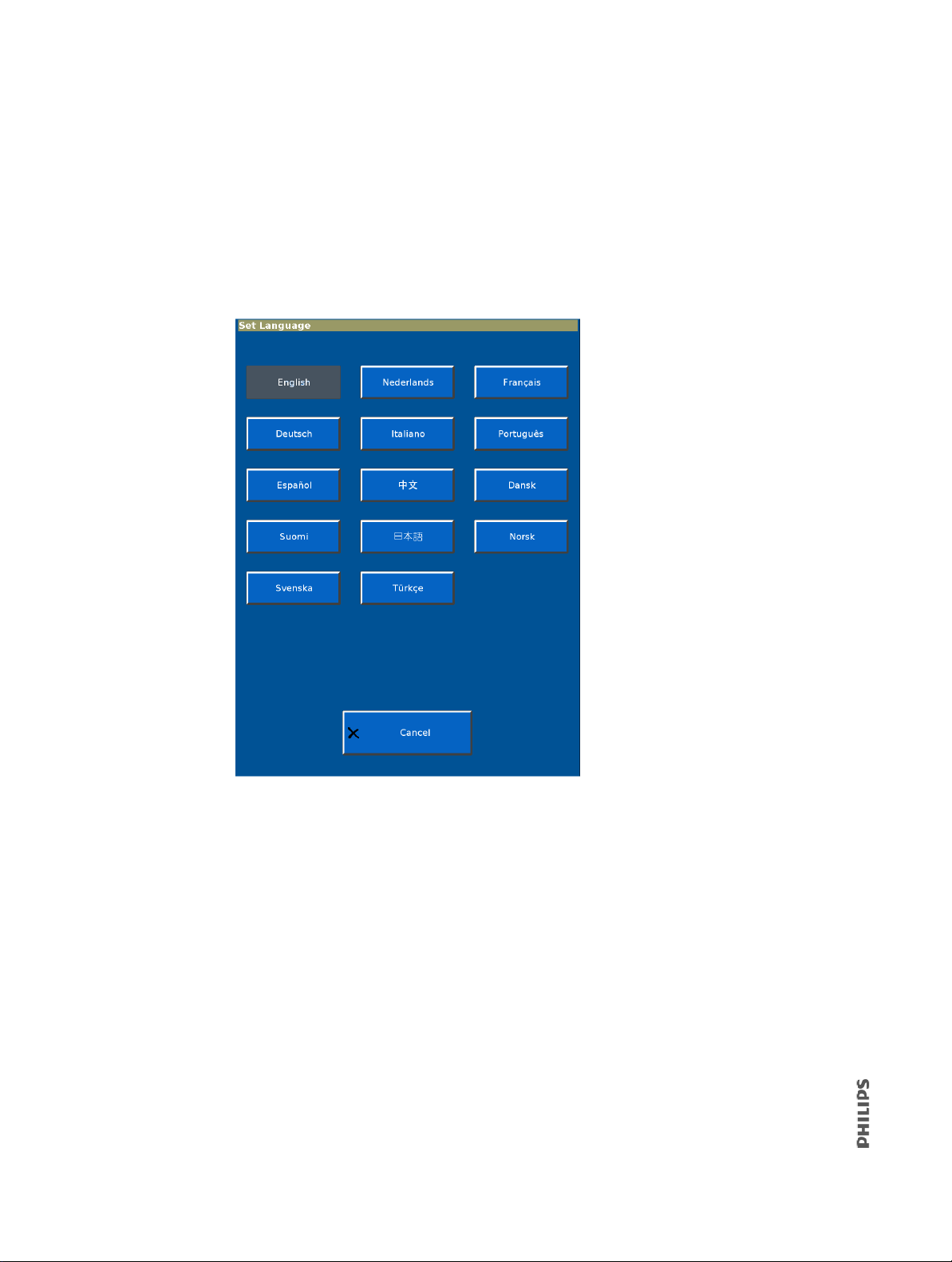
6.1.1 Selecting a Language
Use the Set Language screen to select the language displayed during ventilation mode.
Screens displayed after touching the Ser
English, regardless of the selected language.
1. From the System Settings screen, select Lang
2. Touch the language button on the Set Language screen.
vice button from the Diagnostics Menu appear in
uage.
80 V60/V60 Plus Ventilator Service Manual 1049766 T
Page 81
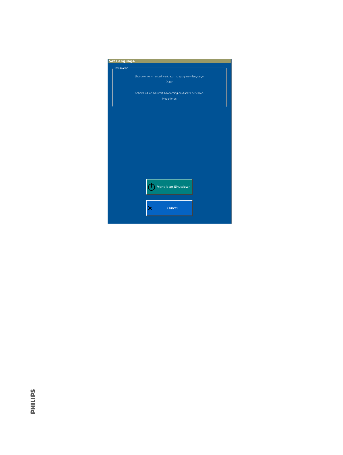
3. The screen shows the selected language.
4. To apply the new language, select Ventilator Shutdown. To exit without changing the
language, select Cancel.
1049766 T V60/V60 Plus Ventilator Service Manual 81
Page 82
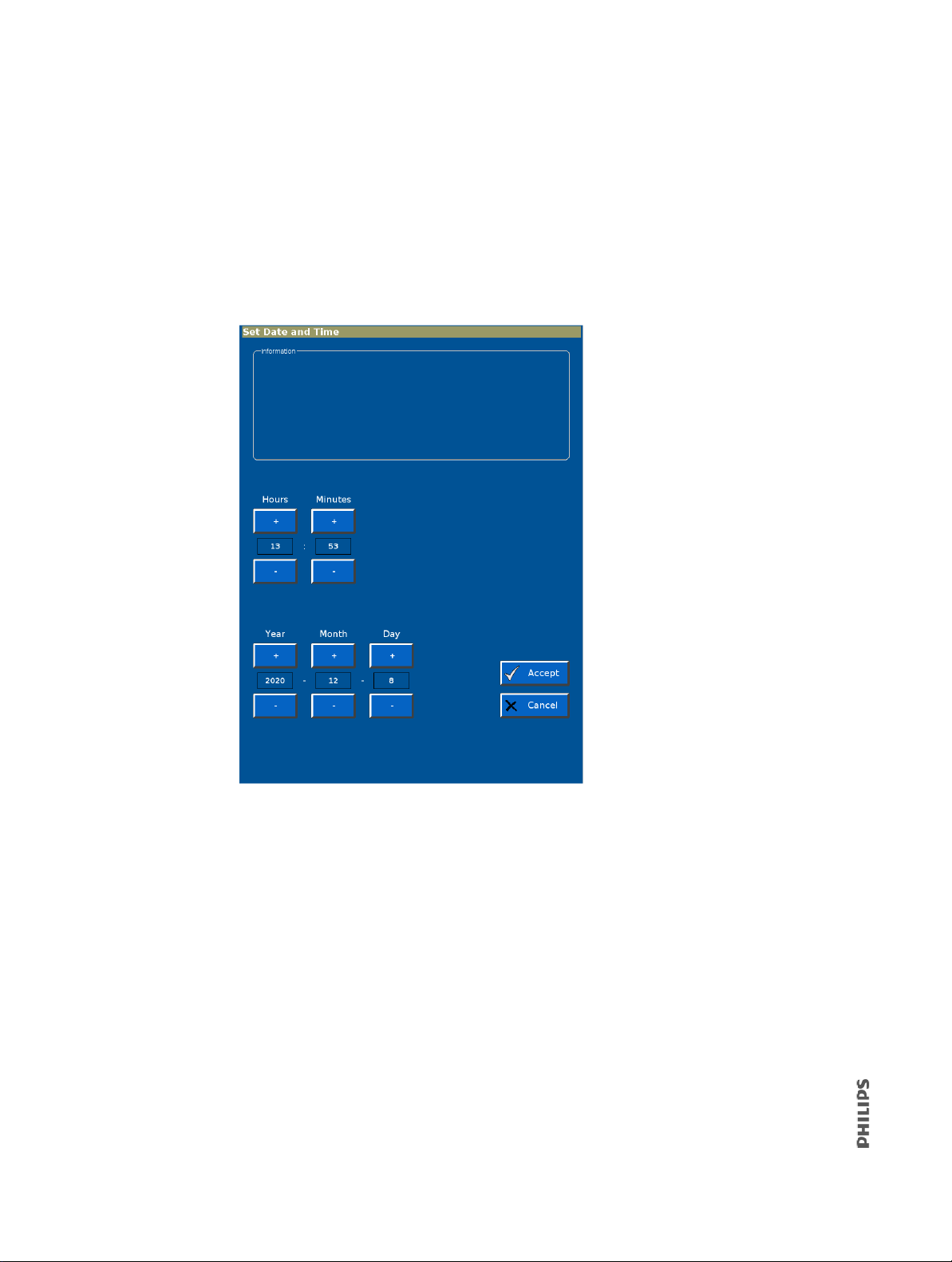
6.1.2 Setting Date and Time
Use the Set Date and Time screen to update the ventilator date and time. The ventilator
uses these settings for the significant event log, and does not adjust settings for daylight
savings.
1. From the System Settings screen, touch Date/Time.
2. Enter the date and time, then touch Accept. To exit without changing the date and
time, touch Cancel.
82 V60/V60 Plus Ventilator Service Manual 1049766 T
Page 83
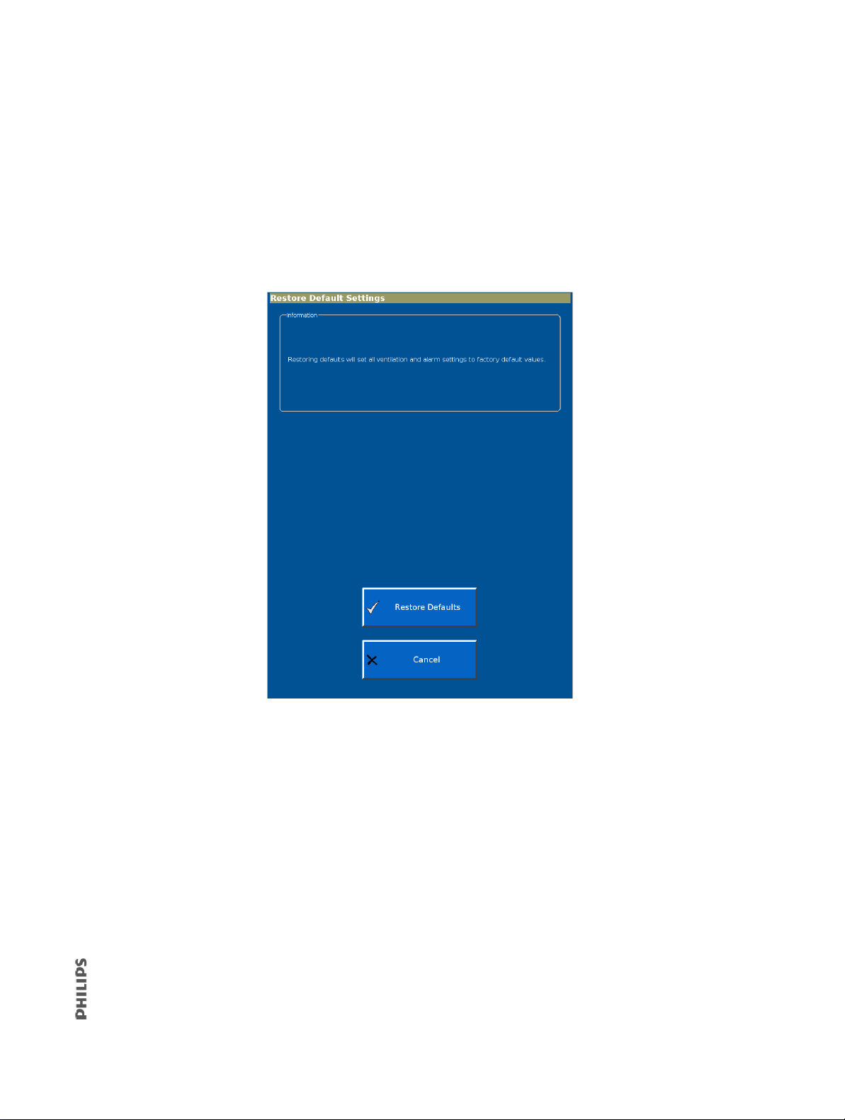
6.1.3 Restoring Default Settings
Use the Restore Default Settings screen to restore ventilation and alarm settings to their
default values. This function does not change other settings such as brightness, loudness,
language, Baud rate, or pressure units.
1. From the System Settings screen, select Restore Default Settings.
2. Select Restore Defaults on the Restore Default Settings screen. To exit without
restoring default settings, select Cancel.
3. When all ventilator and alarm settings have been restored to factory default values,
the screen displays:
Settings have been restored to factory defaults.
1049766 T V60/V60 Plus Ventilator Service Manual 83
Page 84
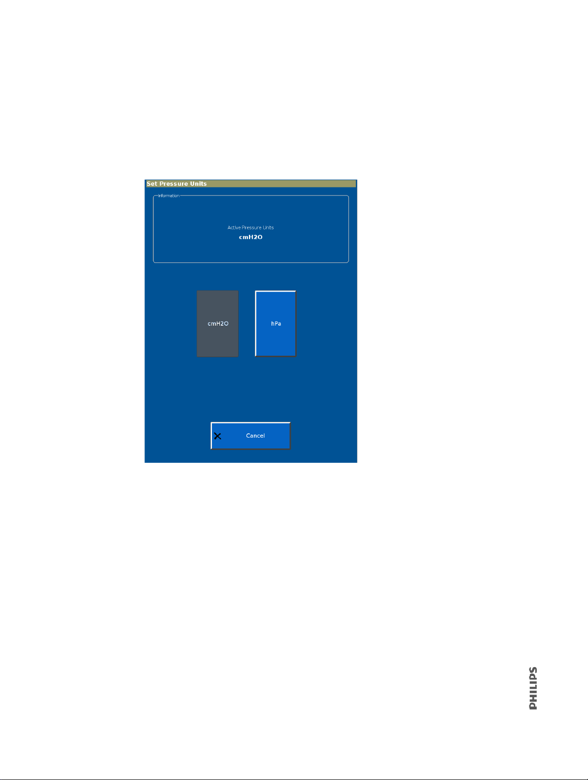
6.1.4 Selecting Pressure Units
Use the Set Pressure Units screen to select what unit of pressure the ventilator displays
during ventilation and Diagnostic modes.
1. From the System Settings screen, touch Pressure Units.
2. Touch the selected pressure unit button on the Set Pressure Units screen.
3. The screen displays the selected pressure unit and this message:
Pressure units will apply after a ventilator shutdown and restart.
4. To apply the new unit of pressure, touch Ventilator Shutdown. To exit without
changing the unit of pressure, touch Cancel.
84 V60/V60 Plus Ventilator Service Manual 1049766 T
Page 85
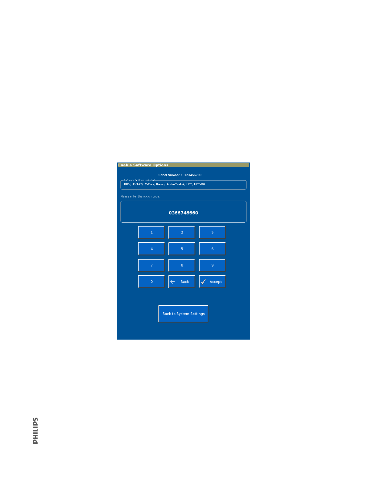
6.1.5 Enabling Software Options
Every software option has a unique enable code for each ventilator. A unique option code is
required for each software option before it can be enabled.
NOTE
Do not install an option until you have verified that the ventilator serial number on the
enclosure matches the serial number shown on the Ventilator Information screen (section
6.2.1). If a serial number must be reprogrammed, do so before enabling an option.
1. From the System Settings screen, touch Software Options.
2. Use the on-screen keypad on the Enable Software Options screen to enter the option
code, then touch Accept.
3. If the option code is invalid, the screen prompts you to reenter.
4. When the software option has been successfully enabled, the screen displays
Enabled: followed by the option name.
5. Repeat as needed to enable additional options.
6. To exit the Enable Software Options screen at any time, touch Back to System
Settings.
1049766 T V60/V60 Plus Ventilator Service Manual 85
Page 86
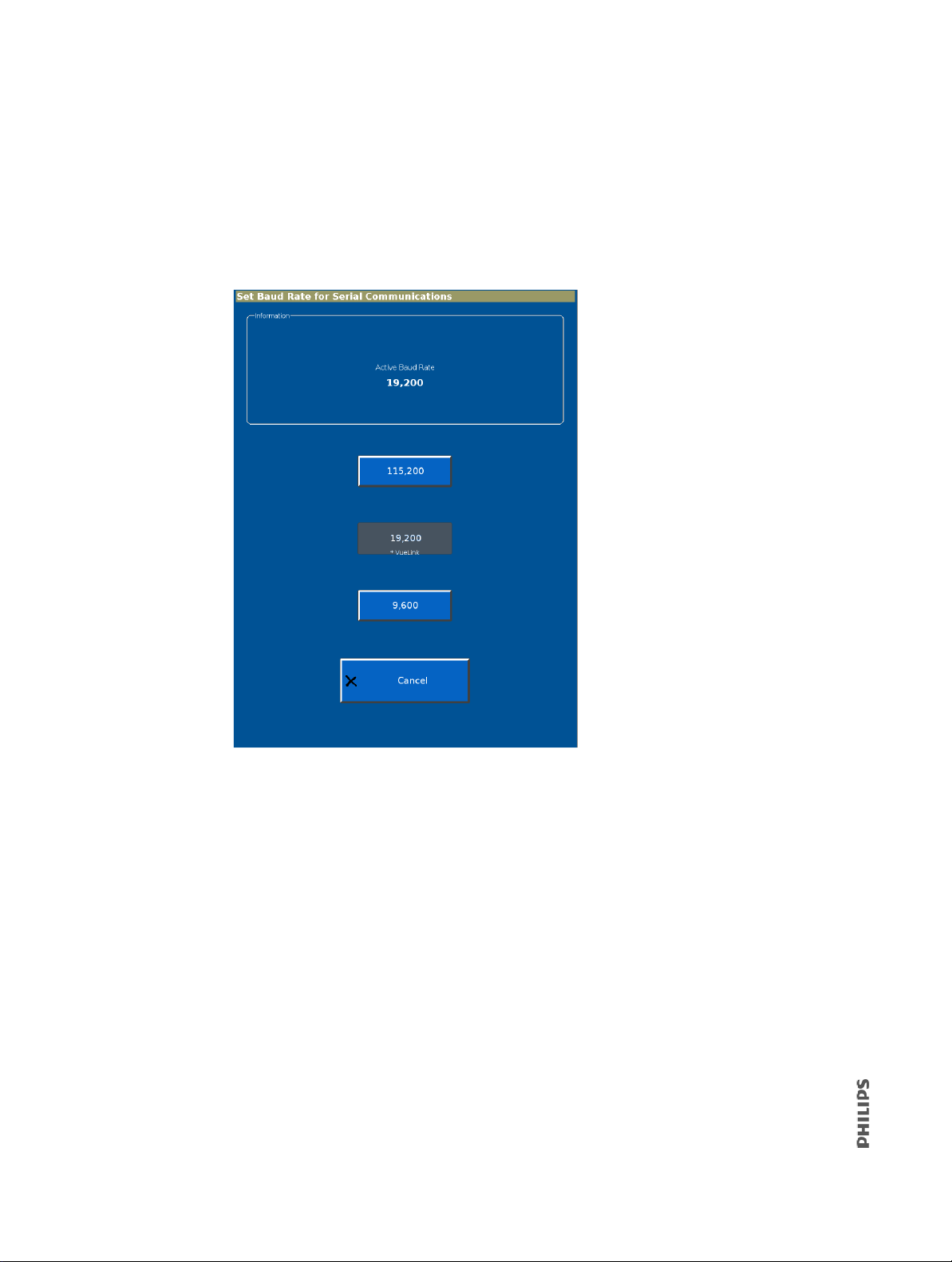
6.1.6 Baud Rate
Use the Set Baud Rate screen to change the ventilator Baud rate for serial communications
during ventilation mode. Diagnostic mode always uses 19,200 Baud.
1. From the System Settings screen, touch Baud R
2. Touch the button to select the Baud rate.
ate.
3. The screen then displays this message: Baud rat
selected Baud rate.
86 V60/V60 Plus Ventilator Service Manual 1049766 T
e is now set to: followed by the
Page 87
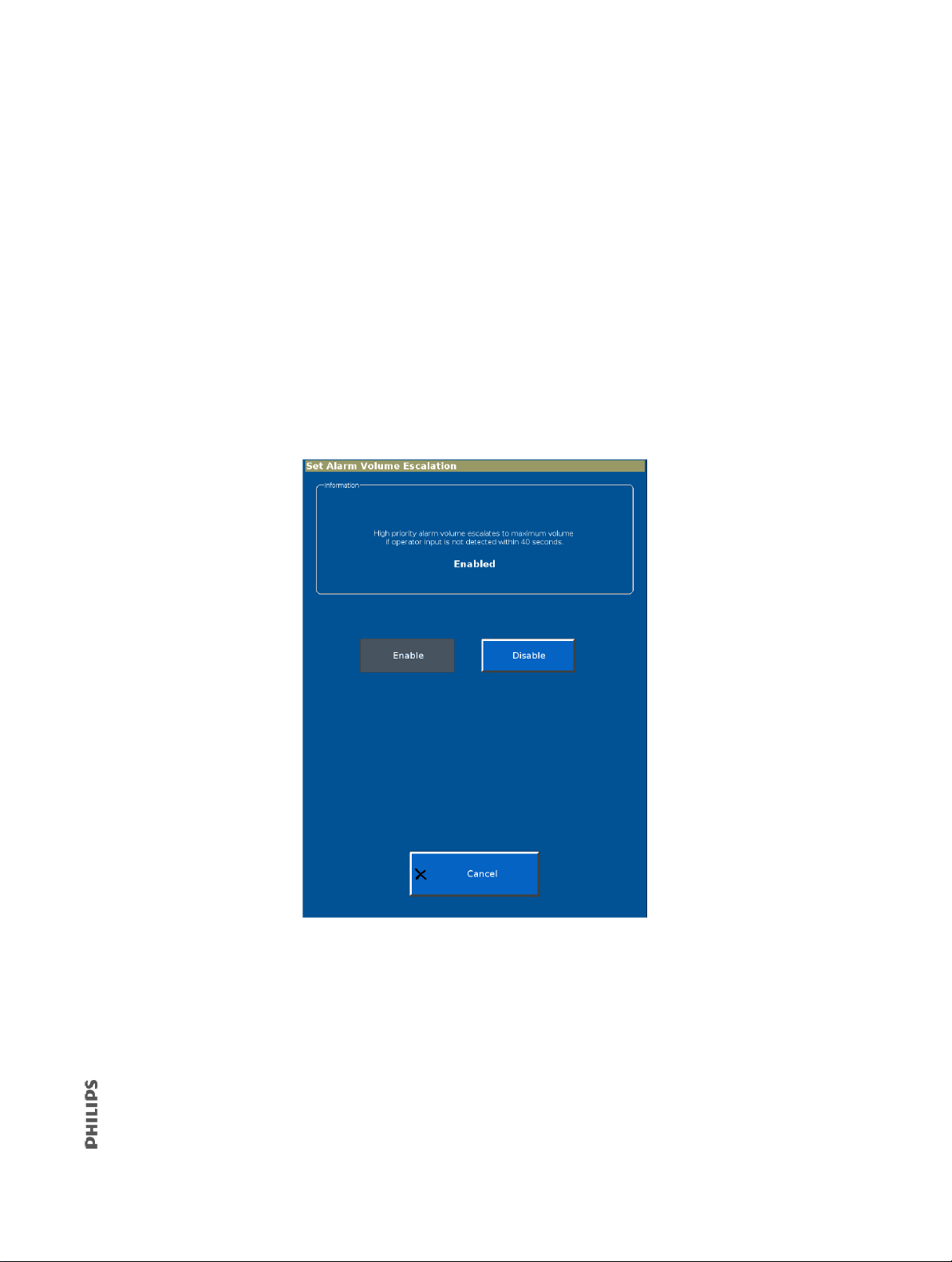
6.1.7 Alarm Volume Escalation
The Alarm Volume Escalation function escalates alarm volume to its maximum if an
operator input is not detected within 40 seconds after a high priority alarm occurs. Alarm
olume automatically returns to the user setting when the ventilator detects a touch on the
v
touchscreen or a button press.
NOTE
The Alarm Escalation function is only available
Enable or disable the Alarm Volume Escalation function from Diagnostic mode:
1. From the System Settings screen, select Alarm Volume Escalation.
2. The current setting appears at the top of the screen.
3. Touch Enable or Disable to change the setting.
in software versions 2.30 or later.
4. The new setting takes effect after turning the ventilator off and on again.
1049766 T V60/V60 Plus Ventilator Service Manual 87
Page 88
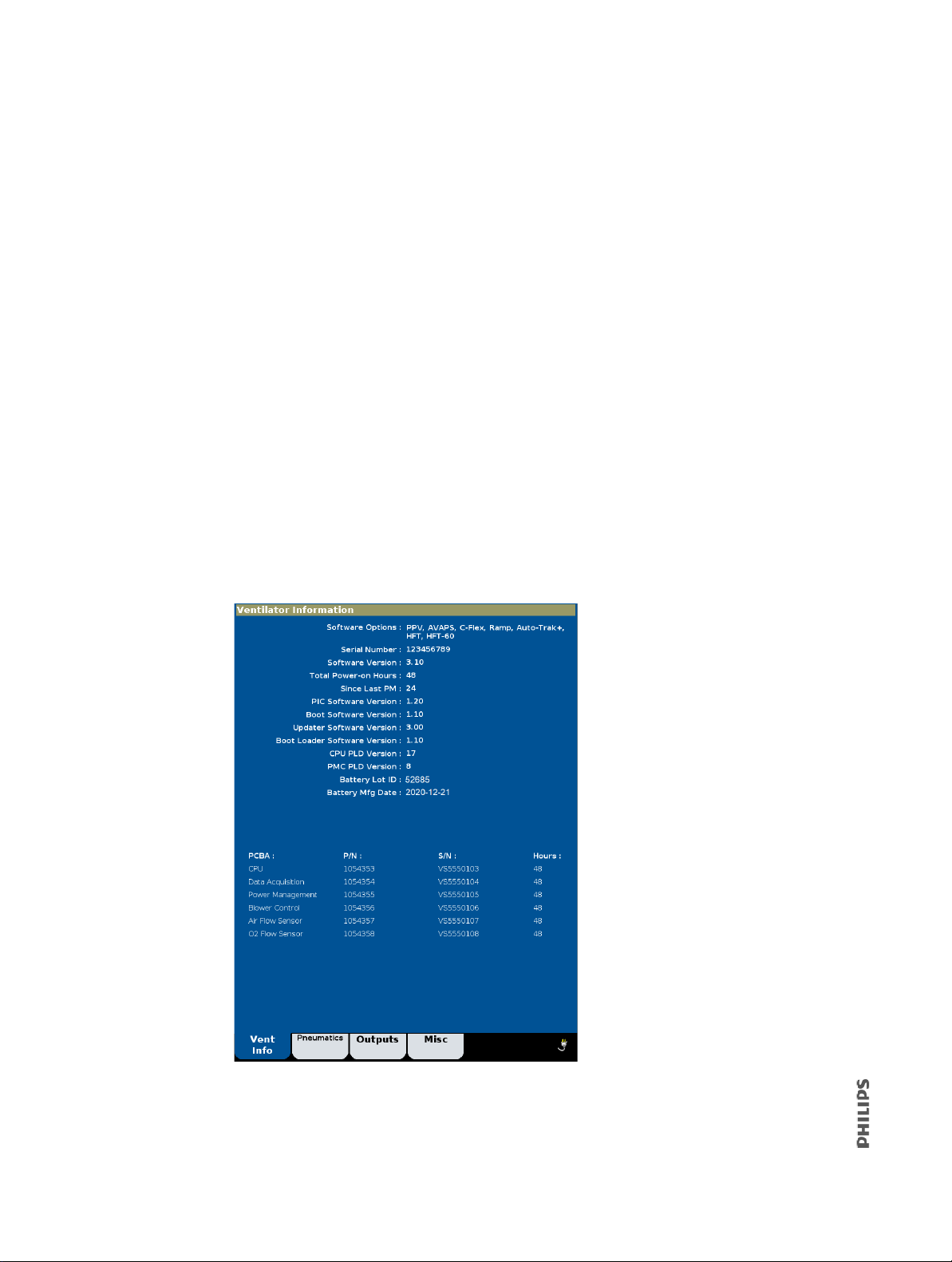
6.2 Service
The Service button provides access to these functions:
• Ventilator information
• Pneumatic controls
• Output controls
• Miscellaneous (significant event log, download mode, and touchscreen diagnostics,
h
igh pressure leak test, and system leak test).
NOTE
Service button functions are intended for use by qualified service technicians.
6.2.1 Viewing Ventilator Information
Ventilator information is used for maintenance and troubleshooting.
1. From the Service screen, touch the Vent Info tab.
2. The Ventilator Information screen displays software options, serial numbers, software
versions, power-on hours, hours since last PM, and information on the internal
battery and PCBAs.
88 V60/V60 Plus Ventilator Service Manual 1049766 T
Page 89
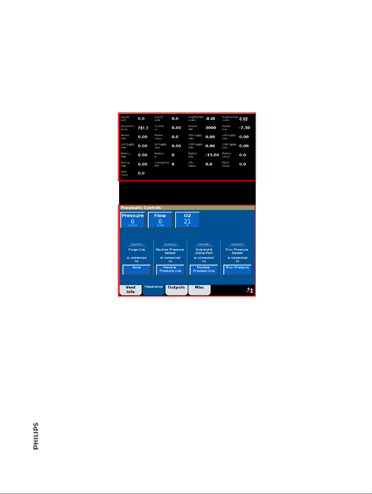
6.2.2 Pneumatic Controls
Real-time pneumatic
information
Pneumatic control
buttons
Use the Pneumatic Controls screen to adjust flows, pressures, O2 concentrations, and the
state of each solenoid.
1. From the Service screen, touch the Pneumatics tab.
2. The screen displays real-time pneumatic information and pneumatic controls.
1049766 T V60/V60 Plus Ventilator Service Manual 89
Page 90
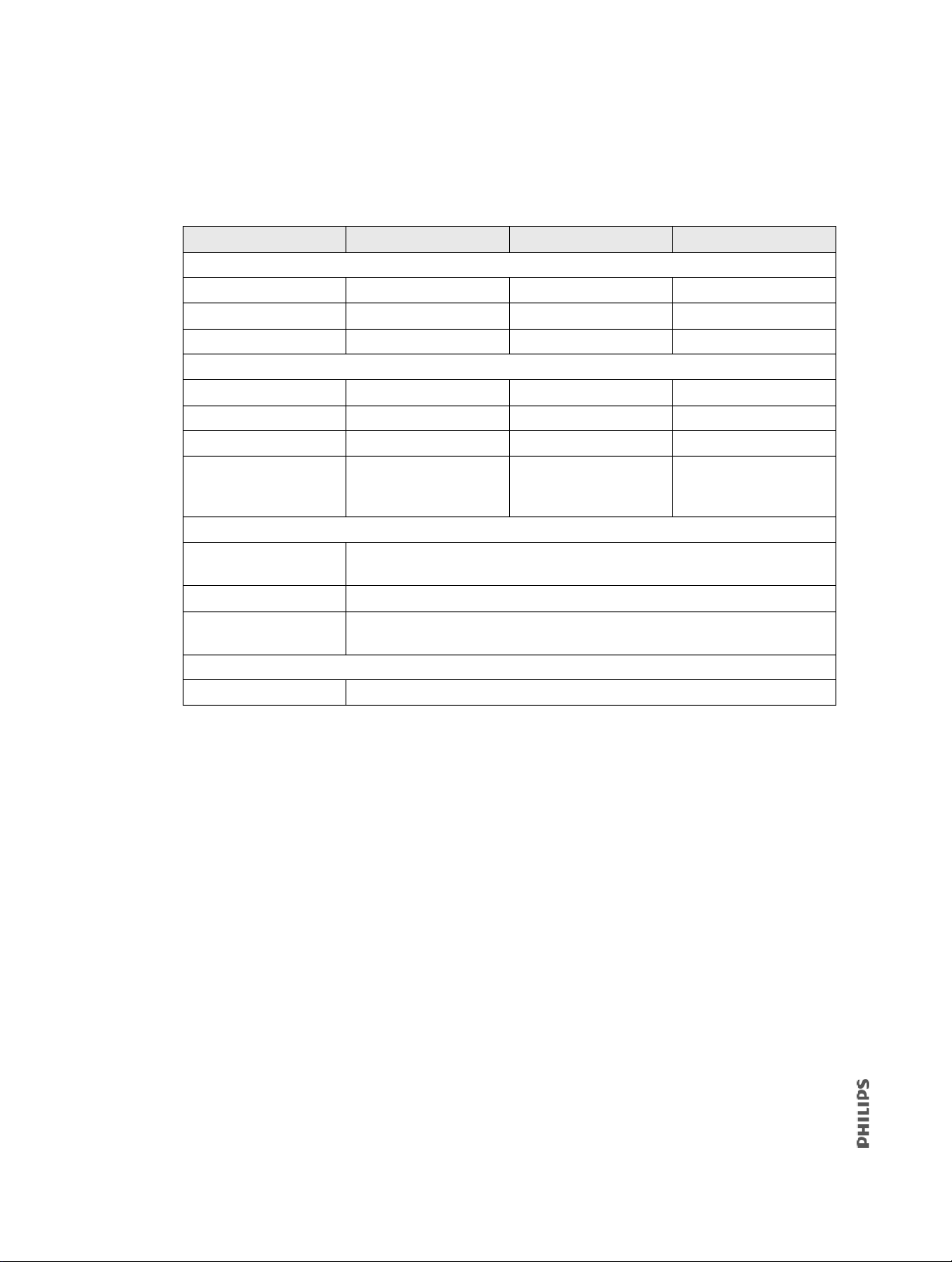
3. Table 6-1 summarizes the acceptable ranges for the pneumatic information that
appears at the top of the screen.
Table 6-1: Acceptable Ranges for Pneumatic Information
Parameter Acceptable range Parameter Acceptable range
Acceptable temperature ranges
Blower Celsius ≤ 95.0 Motor Celsius ≤ 60.0
Battery Celsius ≤ 100.0 Data Celsius ≤ 60.0
CPU Celsius ≤ 60.0
Acceptable voltage ranges
1.8V Supply Volts 1.73 to 1.88 V 24V Supply Volts 22.6 to 26.88 V
3.3V Supply Volts 3.04 to 3.52 V 35V Supply Volts 32.85 to 40.15 V
5V Supply Volts 4.50 to 5.60 V Backup Volts 3.12 to 3.48 V
12V Supply Volts 11.50 to 13.00 Battery Volts 10.00 to 16.90 V
(fully discharged to fully
charged)
Acceptable Amp/RPM ranges
Blower Amp Varies. Occasional 1 A peak at VMOTOR ~ 14.3 V and 21,000 RPM and 0.5 A peak at
VMOTOR ~ 7 V and 10,000 RPM
Blower RPM 0 (blower not turning: 3000 RPM displayed) to ~ 22 V at ~ 31,000 RPM
Battery Amp +2.6 to 0.0 A (battery charging to charge complete); ~ 1.0 A at VBATT ~ 15 V
without blower running
Battery information
Battery % Indicates battery health
90 V60/V60 Plus Ventilator Service Manual 1049766 T
Page 91
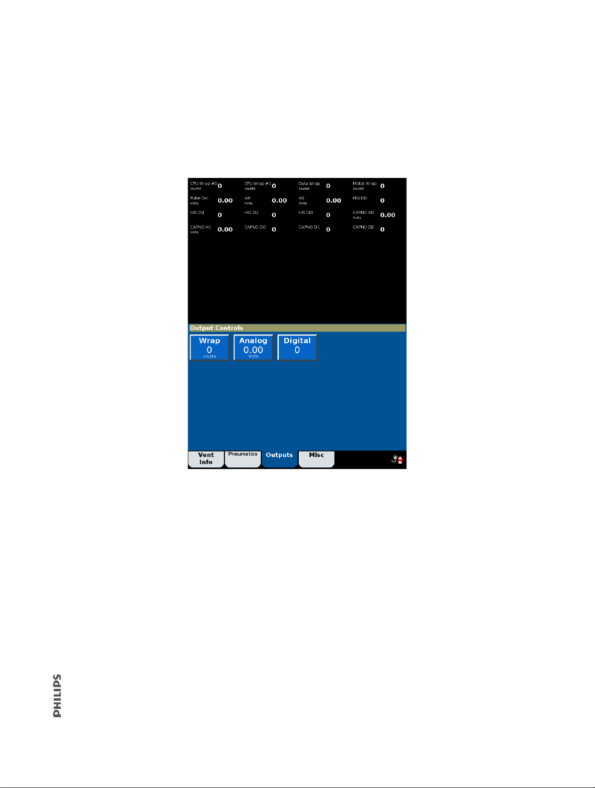
6.2.3 Output Controls
Use the Output Controls screen to set and verify wrap outputs. (Analog and digital outputs
are reserved for internal use only.)
1. From the Service screen, touch the Outputs ta
2. The screen shows diagnostic information and output controls.
b.
Results:
For any of the DAC Wrap signals, the ADC count out should be equal to the DAC count in
± 23 counts over the full range of 0 to 4050 counts. An out-of-specification result could be a
f
ault in any one of the following:
• ADC chip internal fault
• DAC chip internal fault
• Addressing error of the ADC or DAC
• SPI interface failure (DAC only reads data from SPI bus, ADC reads and writes data)
• DAC Wrap feedback path shorted to adjacent signal or open
Note that a fault of Vref may not appear here, as the paired DAC and ADC chips use a
c
ommon reference voltage. There is at least one other ADC input that is generated from a
separate reference (that is, 3.3V supply) that would fail if Vref were off significantly.
1049766 T V60/V60 Plus Ventilator Service Manual 91
Page 92
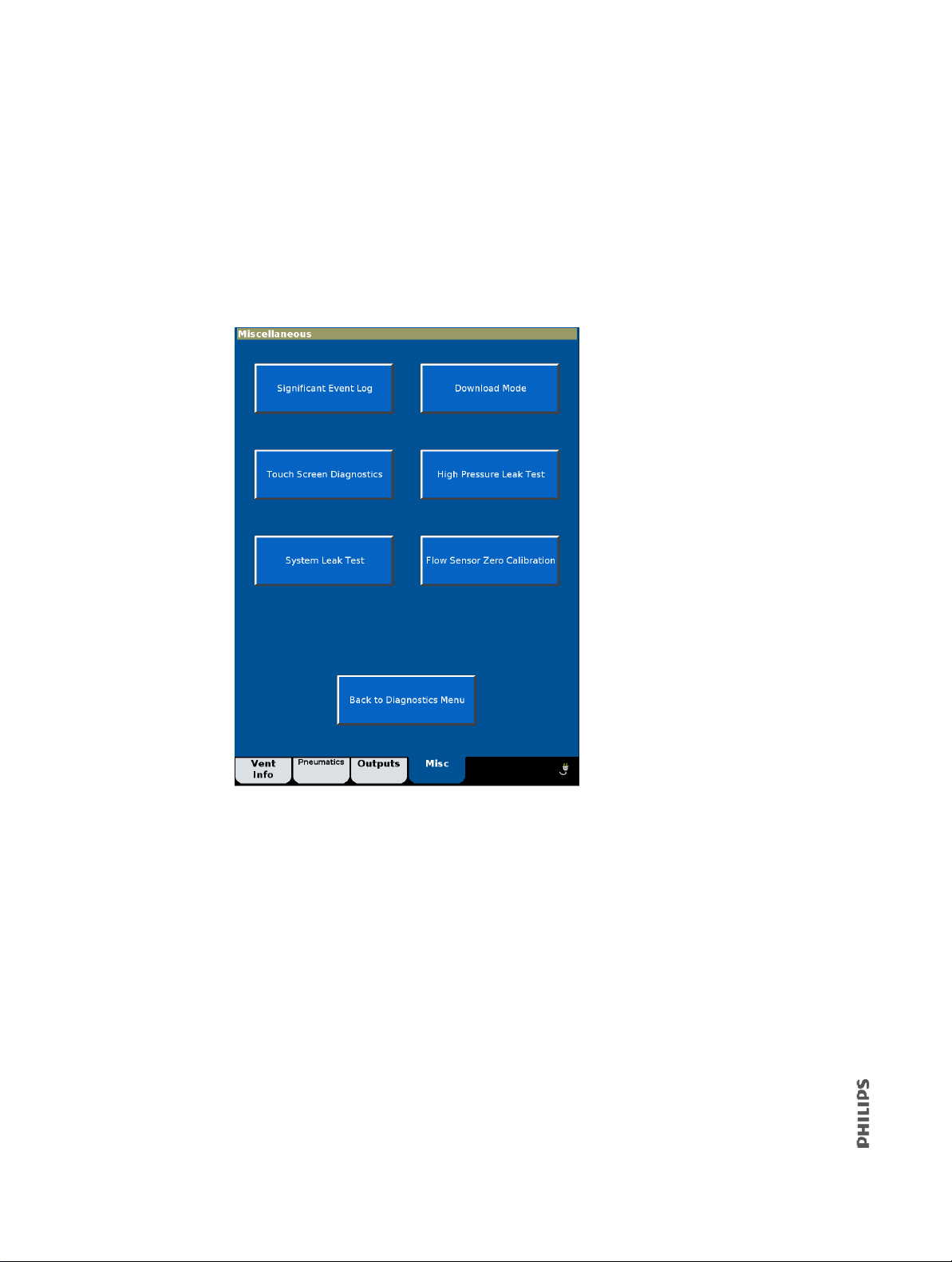
6.2.4 Miscellaneous
Use the Miscellaneous screen to access the significant event log, touchscreen diagnostics,
download mode, high pressure leak test, system leak test, and flow sensor zero calibration.
NOTE
Flow sensor zero calibration is available on ventilators with software version 3.10 or later.
1. From the Service screen, touch the Misc tab.
2. To exit the Miscellaneous screen at any time, touch Back to Diagnostics Menu.
92 V60/V60 Plus Ventilator Service Manual 1049766 T
Page 93
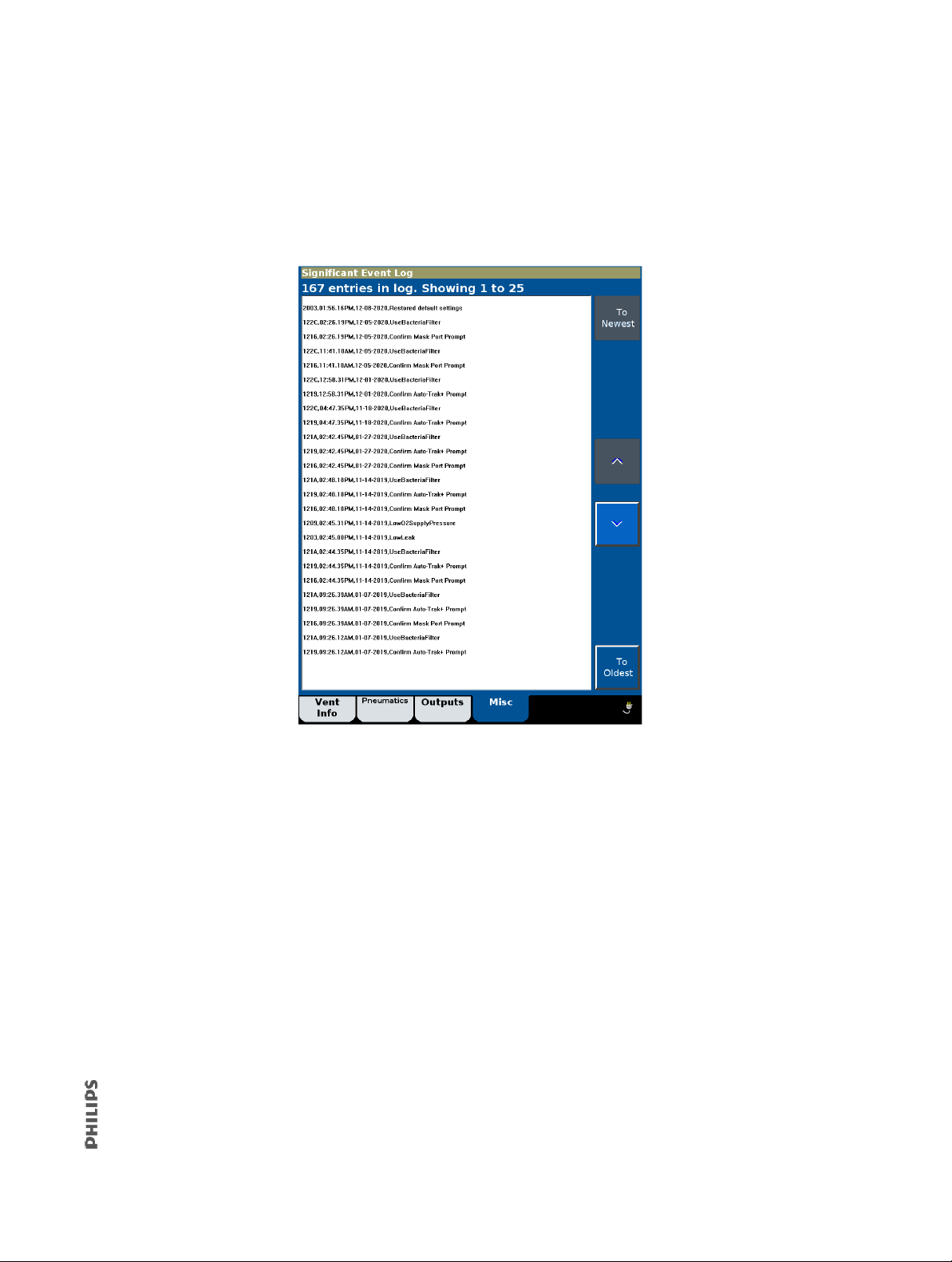
6.2.4.1 Significant Event Log
Use the significant event log to view a log of setting changes, alarms, and diagnostic codes.
1. From the Miscellaneous screen, touch Si
2. Use the arrow buttons to page through the significant event log 25 entries at a time.
gnificant Event Log.
3. To display the beginning or end of the significant event log, select To Newes t or
To O l de s t.
See section 7.2 for information on interpreting the significant event log and saving it to a
computer.
1049766 T V60/V60 Plus Ventilator Service Manual 93
Page 94

6.2.4.2 Download Mode
Use the Download mode screen to load operational software onto the CPU PCBA.
1. From the Miscellaneous screen, touch Download Mode to prepare the ventilator for
a software download. See section 7.5 for more information on downloading software.
2. When the software download is complete, the download complete screen appears.
94 V60/V60 Plus Ventilator Service Manual 1049766 T
Page 95

6.2.4.3 Touchscreen Diagnostics
Use the Touchscreen Diagnostics screen to verify touchscreen x and y coordinates.
1. From the Miscellaneous screen, touch T
2. At the touchscreen diagnostics screen, touch the screen in multiple places to verify
correct touchscreen function.
ouchscreen Diagnostics.
• Press the Accept button to exit the Touchscreen Diagnostics screen and return to the
M
isc tab screen.
• The Touchscreen Diagnostics screen displays a grid with the following pixel line coordinates: 64, 128, 256, 384, 512, 640, 704, and 75
384, 512, 640, 768, 896, and 960 in the Y direction in the portrait oriented screen layout.
• The Touchscreen Diagnostics screen displays a cursor at the calibrated coordinate
ocation where a user touch is detected. The calibrated coordinate location is the ini-
l
tial user touch location adjusted by calibration algorithm.
• The Touchscreen Diagnostics screen displays the ADC (raw) and the cursor (pixel) coordinate values of the location where a user touch is detected.
5 for the X direction and 64, 128, 256,
6.2.4.4 High Pressure Leak Test
Section 9.5.1 describes how to run the high pressure leak test as part of the performance
verification.
1049766 T V60/V60 Plus Ventilator Service Manual 95
Page 96

6.2.4.5 System Leak Test
Section 9.5.2 describes how to run the system leak test as part of the performance
verification.
6.2.4.6 Flow Sensor Zero Calibration
Section 9.9 describes how to run the flow sensor zero calibration as part of the performance
verification.
6.3 Touchscreen Calibration
Use the Touchscreen Calibration button to calibrate the touchscreen x and y coordinates:
1. From the Diagnostics Menu, touch T
NOTE
If the Touchscreen Calibration button does not respond, press the Accept button to
begin.
2. Follow the onscreen instructions to perform the calibration. Touch the middle of each
target with a blunt, narrow object.
ouchscreen Calibration.
96 V60/V60 Plus Ventilator Service Manual 1049766 T
Page 97

6.4 Diagnostic Codes, Alarms, and Troubleshooting
Tabl e 6-2 lists possible ventilator diagnostic codes (generated by the ventilator when an
event such as a setting change or fault condition is detected, or when an alarm indicates
tient or ventilator conditions), and the recommended repair for each. Follow the repair
pa
procedures in order until the problem is resolved.
NOTE
See section 8 for information on removing and replacing ventilator components. See Chapter
9 for performance verification procedures.
Table 6-2: Diagnostic Codes and Troubleshooting
Diagnostic
code
High-priority error conditions that preclude continued safe operation of the ventilator. A Vent Inop alarm displays on the screen,
turns on remote alarm interfaces, and disables O
ventilatory support. CBIT = continuous built-in tests. POST = power on self test.
1000 (CBIT) 3.3 V supply failed.
Twenty consecutive measurements of the 3.30 V supply are greater
than 3.52 V.
1001 (CBIT) 12 V supply failed.
Twenty consecutive measurements of the 12.0 V supply on the
DA PCBA are less than 10.5 V or greater than 13.0 V.
1002 (CBIT) Blower temperature too high.
Blower temperature is greater than or equal to 115º C for longer than
10 min.
1003 (CBIT) Internal temperature high at CPU PCBA.
The internal temperature measured on the CPU PCBA is greater than
70ºC for longer than 5 seconds.
1004 (CBIT) Internal temperature high at DA PCBA.
The internal temperature measured on the DA PCBA is greater than
70ºC for longer than 5 seconds.
Description Recommended repair
1000-10FF Vent Inop Diagnostic Codes
flow and blower operation. Immediately place the patient on another means of
2
Replace the PM PCBA.
Replace the PM PCBA.
1. Verify that the cooling fan is
operational
2. Replace the blower.
3. Replace the MC PCBA.
Replace the CPU PCBA.
1. Verify that the cooling fan is
operational.
2. Replace the DA PCBA.
1005 (CBIT) Internal temperature high at MC PCBA.
The internal temperature measured on the MC PCBA is greater than
70ºC for longer than 5 seconds.
1006 (CBIT) DA PCBA ADC failed.
DAC output is not equal to 150 counts for 6 consecutive
measurements.
1007 (POST)
1008 (CBIT)
1049766 T V60/V60 Plus Ventilator Service Manual 97
Machine and proximal pressure sensors failed.
Auto-zeroing of machine and proximal pressure transducers in POST
failed.
1. Verify that the cooling fan is
operational.
2. Replace the MC PCBA.
1. Replace the DA PCBA to MC PCBA
cable.
2. Replace the DA PCBA.
1. Replace the DA PCBA to MC PCBA
cable.
2. Replace the DA PCBA.
3. Replace the MC PCBA.
4. Replace the PM PCBA.
5. Replace the CPU PCBA.
Page 98

Table 6-2: Diagnostic Codes and Troubleshooting (Continued)
Diagnostic
code
1009 Pressure regulation high.
The proximal pressure is 25 cmH2O greater than the pressure limit
listed below and greater than the HIP setting for 1 second:
Pressure limit
•CPAP mode: CPAP setting
•S/T mode: IPAP setting
•PCV mode: IPAP setting
• AVAPS mode: IPAP Max Pressure setting
• PPV mode: IPAP setting for machine-initiated breaths, PPV Max P
for patient-initiated breath
or
The measured machine pressure is 25 cmH
limit listed below + the estimated pressure drop due to the air flow
through the patient circuit, and it is greater than HIP setting for
1 second:
Pressure limit
•CPAP mode: CPAP setting
•S/T mode: IPAP setting
•PCV mode: IPAP setting
• AVAPS mode: IPAP Max Pressure setting
• PPV mode: IPAP setting for machine-initiated breaths, PPV Max P
for patient-initiated breath
or
The measured machine or proximal pressure is ≥ 64 cmH2O for
1 second.
or
For HFT, the measured machine or proximal pressure > 59 cmH2O for
1 second.
Description Recommended repair
1. Verify the proximal and machine
tubing connections.
2. Verify the pressures and flows.
3. Replace the DA PCBA.
4. Replace the MC PCBA.
O greater than the pressure
2
100A (CBIT) DA PCBA ADC reference failed.
The ADC reading from the measured 3.3 V supply is less than
2413 – 290 counts or greater than 2869 + 165 counts for 6 consecutive
samples, scheduled to be 10 ms apart.
1. Verify 3.3V in diagnostics.
2. Verify 2.5V ref on DA PCBA (see
Figure 6-1).
3. Replace the DA PCBA to MC PCBA
cable.
4. Replace the DA PCBA.
5. Replace the PM PCBA.
6. Replace the CPU
100B (POST) Watchdog test failed.
Watchdog timer was not strobed as expected with an 8-ms and a 12-ms
window.
1. Replace the CPU PCBA.
2. Replace the MC PCBA.
3. Replace the flow sensor assembly.
98 V60/V60 Plus Ventilator Service Manual 1049766 T
Page 99

Table 6-2: Diagnostic Codes and Troubleshooting (Continued)
Diagnostic
code
High-priority error conditions that require immediate attention. Ventilator continues to operate with limited performance. Do not
use the ventilator until the problem is corrected. CBIT = continuous built-in tests. POST = power on self test.
1100 (CBIT) Program CRC test failed.
The CRC of the ventilator program block in RAM is computed
periodically and compared with stored CRC value to ensure that the
program image is valid. When the CRC values do not match, the
ventilator restarts.
1101 Ventilator restarted due to anomalies detected during operation.
This could include invalid or corrupted information, unanticipated
situations, or object allocation errors.
NOTE
If diagnostic code 1101 occurs in conjunction with diagnostic code 3007
(software exception), no action is required.
1102 (POST) Primary alarm failed.
When the Primary Audible Alarm Test fails for either speaker, alarms
are annunciated using both the primary and backup audio devices.
Description Recommended repair
1100-11FF Check Vent Diagnostic Codes
1. Reinstall operational software.
2. Replace the CPU PCBA.
1. Reinstall operational software.
2. Replace the CPU PCBA.
1. Listen for audible sound from the
speakers.
2. Verify that the speakers are
connected.
3. Verify that the braided wires are not
touching the speaker housing.
4. Verify that the resistance of each
speaker is 6.8 to 9.2 Ω (Figure 6-2).
5. Replace speaker #1 (MC PCBA).
6. Replace speaker #2 (PM PCBA).
7. Replace the CPU PCBA.
1104 (POST) Backup alarm failed.
When the Backup Audible Alarm Test fails, alarms normally
annunciated by the backup audio device use the primary speakers.
1105 (POST) Alarm LED failed.
Either (1) the LED is on and the voltage signal from the power
management controller is less than 1.0 V or greater than 2.5 V or (2)
the LED is off and the voltage is greater than or equal to 0.5 V.
1106 (POST) Machine pressure sensor calibration data error.
When the integrity of the calibration data cannot be verified for the
machine pressure transducer, the proximal pressure sensor is used to
measure machine pressure (solenoid 3 is de-energized; solenoid 4 is
energized). Proximal pressure is not measured and pressure-related
alarms are compromised.
1049766 T V60/V60 Plus Ventilator Service Manual 99
1. Replace the MC PCBA.
2. Replace the CPU PCBA.
3. Replace the PM PCBA.
1. Disconnect all power (section 8.1). If
this code does not recur when power
is reconnected, no further action is
required.
2. Replace the power switch overlay.
3. Replace the PM PCBA.
4. Replace the UI PCBA.
5. Replace the UI to PM PCBA cable.
Replace the DA PCBA.
Page 100

Table 6-2: Diagnostic Codes and Troubleshooting (Continued)
Diagnostic
code
Description Recommended repair
1107 (POST) Proximal pressure sensor calibration data error.
When the integrity of the calibration data cannot be verified for the
proximal pressure transducer, the proximal pressure is not measured
and pressure-related alarms are compromised.
1108 (POST)
1109 (CBIT)
Machine pressure sensor autozero failed.
The proximal pressure sensor is used to measure machine pressure
(solenoid 3 de-energized; solenoid 4 energized), the proximal pressure
is not measured, and pressure-related alarms are compromised.
110A (POST)
110B (CBIT)
Proximal pressure sensor autozero failed.
The proximal pressure is not measured and pressure-related alarms are
compromised.
110C (CBIT) Machine pressure sensor range error.
The proximal pressure sensor is used to measure machine pressure
(solenoid 3 de-energized; solenoid 4 energized), proximal pressure is
not measured, and pressure-related alarms are compromised.
110D (CBIT) Proximal pressure sensor range error.
The proximal pressure is not measured and pressure-related alarms are
compromised.
Replace the DA PCBA.
1. Verify pin alignment between
solenoids and the DA PCBA.
2. Replace the machine auto-zero
solenoid (SOL 2 and SOL 4).
3. Replace the DA PCBA.
1. Verify pin alignment between
solenoids and the DA PCBA.
2. Replace the proximal auto-zero
solenoid (SOL 3 and SOL 4).
3. Replace the DA PCBA.
1. Cycle the ventilator power to reset the
proximal pressure sensor.
2. Replace the DA PCBA.
1. Cycle the ventilator power to reset
proximal pressure sensor.
2. Replace the DA PCBA.
110E (POST) Air flow sensor calibration data error.
When the integrity of the calibration data cannot be verified for the air
flow sensor, the ventilator continues to operate with air only. Flowrelated patient data is disabled. In AVAPS mode, the default volume is
used. Standby is disabled. Volume, leak, disconnect, and occlusion
alarms are compromised.
110F (POST) O
flow sensor calibration data error.
2
When the integrity of the O2 flow sensor calibration data cannot be
verified, the ventilator continues to operate with air only.
1110 (POST) O
pressure sensor calibration data error.
2
When the integrity of the O
supply pressure transducer calibration
2
data cannot be verified, the ventilator continues to operate with air
only.
1111 (CBIT) O
device failed.
2
The ventilator continues to deliver breaths targeting the 21% O2
concentration setting regardless of the user-set O
setting.
2
1. Perform the flow sensor zero
calibration.
2. Replace the flow sensor assembly.
3. Replace the DA PCBA.
1. Perform the flow sensor zero
calibration.
2. Replace the flow sensor assembly.
3. Replace the DA PCBA.
Replace the DA PCBA.
1. Verify that the O
source pressure is
2
40 to 87 psig.
2. Perform the high pressure leak test
(section 9.5).
3. Verify O
4. Inspect the O
flows (section 9.12).
2
inlet filter for
2
contamination or debris.
5. Replace the O2 valve.
6. Replace the DA PCBA.
100 V60/V60 Plus Ventilator Service Manual 1049766 T
 Loading...