

Page 1

Respironics V200 Ventilator
Operator’s Manual
1057983 50
Page 2

For Technical Support and Customer Service, contact:
USA and Canada: 1-800-345-6443 or 724-387-4000
Respironics Europe, Africa, Middle East: +33-1-47-52-30-00
Respironics Asia Pacific: +852-3194-2280
Facsimile: 724-387-5012
USA
Respironics California, Inc.
2271 Cosmos Court
Carlsbad, CA 92011
Email and web addresses
service@philips.com
clinical@philips.com
www.philips.com\healthcare
Authorized European address
Respironics Deutschland GmbH
EC REP
Gewerbestrasse 17
D-82211 Herrsching
Germany
+49-8-15-29-30-60
© 2009 Respironics and its affiliates.
All rights reserved.
This work is protected under T itle 17 of the United States copyright code and is the sole property of Respironics.
No part of this document may be copied or otherwise reproduced, or stored in any electronic information
retrieval system, except as specifically permitted under United States copyright law, without the prior written
consent of Respironics.
Page 3

Table of Contents
1. Introduction and Intended Use. . . . . . . . . . . . . . . . . . . . . . . . . . . . . . . . . . 1-1
2. Warnings, Cautions, and Notes . . . . . . . . . . . . . . . . . . . . . . . . . . . . . . . . . 2-1
Summary of Warnings, Cautions, and Notes . . . . . . . . . . . . . . . . . . . . . . . . . . . 2-1
3. Symbols . . . . . . . . . . . . . . . . . . . . . . . . . . . . . . . . . . . . . . . . . . . . . . . . . . . 3-1
4. Getting Started . . . . . . . . . . . . . . . . . . . . . . . . . . . . . . . . . . . . . . . . . . . . . . 4-1
Unpacking . . . . . . . . . . . . . . . . . . . . . . . . . . . . . . . . . . . . . . . . . . . . . . . . . . 4-1
Inspection. . . . . . . . . . . . . . . . . . . . . . . . . . . . . . . . . . . . . . . . . . . . . . . . . . . 4-2
List of Parts and Accessories . . . . . . . . . . . . . . . . . . . . . . . . . . . . . . . . . . . . . 4-2
Repacking. . . . . . . . . . . . . . . . . . . . . . . . . . . . . . . . . . . . . . . . . . . . . . . . . . . 4-3
Ventilator Positioning. . . . . . . . . . . . . . . . . . . . . . . . . . . . . . . . . . . . . . . . . . . 4-4
Backup Battery . . . . . . . . . . . . . . . . . . . . . . . . . . . . . . . . . . . . . . . . . . . . . . . 4-4
Inspiratory Bacteria Filter Installation . . . . . . . . . . . . . . . . . . . . . . . . . . . . . . 4-16
Heated Expiratory Bacteria Filter Installation . . . . . . . . . . . . . . . . . . . . . . . . . 4-18
Oxygen Source Connection . . . . . . . . . . . . . . . . . . . . . . . . . . . . . . . . . . . . . . 4-20
Patient Circuit Flex Arm Installati on . . . . . . . . . . . . . . . . . . . . . . . . . . . . . . . 4-22
5. Setup . . . . . . . . . . . . . . . . . . . . . . . . . . . . . . . . . . . . . . . . . . . . . . . . . . . . . 5-1
Back Panel Connections and Control s . . . . . . . . . . . . . . . . . . . . . . . . . . . . . . . 5-1
Connecting AC Power Cord . . . . . . . . . . . . . . . . . . . . . . . . . . . . . . . . . . . . . . . 5-3
Power On/Off. . . . . . . . . . . . . . . . . . . . . . . . . . . . . . . . . . . . . . . . . . . . . . . . . 5-4
Entering Diagnostic Mode. . . . . . . . . . . . . . . . . . . . . . . . . . . . . . . . . . . . . . . . 5-5
User Configuration Screen . . . . . . . . . . . . . . . . . . . . . . . . . . . . . . . . . . . . . . . 5-7
Backup Battery . . . . . . . . . . . . . . . . . . . . . . . . . . . . . . . . . . . . . . . . . . . . . . 5-11
Extended Self Test (EST) . . . . . . . . . . . . . . . . . . . . . . . . . . . . . . . . . . . . . . . 5-12
6. Connecting Additional Equipment . . . . . . . . . . . . . . . . . . . . . . . . . . . . . . . 6-1
Communication Interface . . . . . . . . . . . . . . . . . . . . . . . . . . . . . . . . . . . . . . . . 6-1
Connecting Serial Communications Devices . . . . . . . . . . . . . . . . . . . . . . . . . . . 6-2
Connecting Remote Alarm Port . . . . . . . . . . . . . . . . . . . . . . . . . . . . . . . . . . . . 6-2
Connecting Humidifier. . . . . . . . . . . . . . . . . . . . . . . . . . . . . . . . . . . . . . . . . . 6-3
Connecting the Patient Circuit . . . . . . . . . . . . . . . . . . . . . . . . . . . . . . . . . . . . 6-5
Connecting the Analog Port . . . . . . . . . . . . . . . . . . . . . . . . . . . . . . . . . . . . . . 6-7
7. Operating Theory . . . . . . . . . . . . . . . . . . . . . . . . . . . . . . . . . . . . . . . . . . . . 7-1
Introduction . . . . . . . . . . . . . . . . . . . . . . . . . . . . . . . . . . . . . . . . . . . . . . . . . 7-1
System Overview . . . . . . . . . . . . . . . . . . . . . . . . . . . . . . . . . . . . . . . . . . . . . . 7-1
Ventilator Breath Types . . . . . . . . . . . . . . . . . . . . . . . . . . . . . . . . . . . . . . . . . 7-1
Ventilation Modes Common to VCV and PCV. . . . . . . . . . . . . . . . . . . . . . . . . . . 7-3
Ventilation Modes Common to NPPV . . . . . . . . . . . . . . . . . . . . . . . . . . . . . . . . 7-6
Emergency Modes of Ventilation . . . . . . . . . . . . . . . . . . . . . . . . . . . . . . . . . . . 7-7
REF 1057983 A Respironics V200 Ventilator Operator’s Manual iii
Page 4

Contents
8. Operating Instructions . . . . . . . . . . . . . . . . . . . . . . . . . . . . . . . . . . . . . . . . . 8-1
Overview. . . . . . . . . . . . . . . . . . . . . . . . . . . . . . . . . . . . . . . . . . . . . . . . . . . . . 8-1
The Front Panel. . . . . . . . . . . . . . . . . . . . . . . . . . . . . . . . . . . . . . . . . . . . . . . . 8-3
Ventilator Screens . . . . . . . . . . . . . . . . . . . . . . . . . . . . . . . . . . . . . . . . . . . . . 8-11
Settings Screens . . . . . . . . . . . . . . . . . . . . . . . . . . . . . . . . . . . . . . . . . . . . . . 8-14
Selecting a New Ventilation Breath Type (VCV, PCV, or NPPV). . . . . . . . . . . . . . 8-23
Selecting the Mode (A/C-SIMV-CPAP or Spont-Spont/T) . . . . . . . . . . . . . . . . . . 8-26
Apnea Ventilation . . . . . . . . . . . . . . . . . . . . . . . . . . . . . . . . . . . . . . . . . . . . . 8-27
Patient Data Screen. . . . . . . . . . . . . . . . . . . . . . . . . . . . . . . . . . . . . . . . . . . . 8-28
Monitor Screen . . . . . . . . . . . . . . . . . . . . . . . . . . . . . . . . . . . . . . . . . . . . . . . 8-29
Special Procedures . . . . . . . . . . . . . . . . . . . . . . . . . . . . . . . . . . . . . . . . . . . . 8-31
Preoperational Procedure . . . . . . . . . . . . . . . . . . . . . . . . . . . . . . . . . . . . . . . . 8-32
Alarm Testing Procedure . . . . . . . . . . . . . . . . . . . . . . . . . . . . . . . . . . . . . . . . 8-34
Where To Go For Help . . . . . . . . . . . . . . . . . . . . . . . . . . . . . . . . . . . . . . . . . . 8-34
9. Alarms . . . . . . . . . . . . . . . . . . . . . . . . . . . . . . . . . . . . . . . . . . . . . . . . . . . . . 9-1
Introduction . . . . . . . . . . . . . . . . . . . . . . . . . . . . . . . . . . . . . . . . . . . . . . . . . . 9-1
Visual Alarms . . . . . . . . . . . . . . . . . . . . . . . . . . . . . . . . . . . . . . . . . . . . . . . . . 9-1
Audible Alarms . . . . . . . . . . . . . . . . . . . . . . . . . . . . . . . . . . . . . . . . . . . . . . . . 9-2
Alarm Reset . . . . . . . . . . . . . . . . . . . . . . . . . . . . . . . . . . . . . . . . . . . . . . . . . . 9-3
Alert Messages . . . . . . . . . . . . . . . . . . . . . . . . . . . . . . . . . . . . . . . . . . . . . . . . 9-4
Alarm Indicators . . . . . . . . . . . . . . . . . . . . . . . . . . . . . . . . . . . . . . . . . . . . . . . 9-9
10. Care and Maintenance. . . . . . . . . . . . . . . . . . . . . . . . . . . . . . . . . . . . . . . . 10-1
General Information. . . . . . . . . . . . . . . . . . . . . . . . . . . . . . . . . . . . . . . . . . . . 10-1
Cleaning. . . . . . . . . . . . . . . . . . . . . . . . . . . . . . . . . . . . . . . . . . . . . . . . . . . . 10-1
Sterilization . . . . . . . . . . . . . . . . . . . . . . . . . . . . . . . . . . . . . . . . . . . . . . . . . 10-2
Bacteria Filters . . . . . . . . . . . . . . . . . . . . . . . . . . . . . . . . . . . . . . . . . . . . . . . 10-4
Periodic Maintenance . . . . . . . . . . . . . . . . . . . . . . . . . . . . . . . . . . . . . . . . . . 10-7
Storage. . . . . . . . . . . . . . . . . . . . . . . . . . . . . . . . . . . . . . . . . . . . . . . . . . . . 10-10
Repairs. . . . . . . . . . . . . . . . . . . . . . . . . . . . . . . . . . . . . . . . . . . . . . . . . . . . 10-10
11. Diagnostics. . . . . . . . . . . . . . . . . . . . . . . . . . . . . . . . . . . . . . . . . . . . . . . . . 11-1
Entering Diagnostic Mode. . . . . . . . . . . . . . . . . . . . . . . . . . . . . . . . . . . . . . . . 11-2
Diagnostic Functions . . . . . . . . . . . . . . . . . . . . . . . . . . . . . . . . . . . . . . . . . . . 11-3
Extended Self Test (EST) . . . . . . . . . . . . . . . . . . . . . . . . . . . . . . . . . . . . . . . . 11-4
Self Test. . . . . . . . . . . . . . . . . . . . . . . . . . . . . . . . . . . . . . . . . . . . . . . . . . . 11-10
12. Technical Specifications. . . . . . . . . . . . . . . . . . . . . . . . . . . . . . . . . . . . . . 12-1
Breath Types. . . . . . . . . . . . . . . . . . . . . . . . . . . . . . . . . . . . . . . . . . . . . . . . . 12-1
Modes . . . . . . . . . . . . . . . . . . . . . . . . . . . . . . . . . . . . . . . . . . . . . . . . . . . . . 12-1
Volume Ventilation Settings, Ranges and Resolution . . . . . . . . . . . . . . . . . . . . . 12-1
Pressure Control Ventilation Settings, Ranges and Resolution . . . . . . . . . . . . . . 12-2
Non-Invasive Positive Pressure Ventilation Settings, Ranges and Resolution . . . . 12-3
Apnea Ventilation . . . . . . . . . . . . . . . . . . . . . . . . . . . . . . . . . . . . . . . . . . . . . 12-3
Value Entry Message . . . . . . . . . . . . . . . . . . . . . . . . . . . . . . . . . . . . . . . . . . . 12-4
iv Respironics V200 Ventilator Operator’s Manual REF 1057983 A
Page 5

Contents
Patient Data Screen. . . . . . . . . . . . . . . . . . . . . . . . . . . . . . . . . . . . . . . . . . . 12-5
Front Panel Keys . . . . . . . . . . . . . . . . . . . . . . . . . . . . . . . . . . . . . . . . . . . . . 12-6
Level Controls . . . . . . . . . . . . . . . . . . . . . . . . . . . . . . . . . . . . . . . . . . . . . . . 12-7
Calculated Values from Expiratory Hold Maneuver. . . . . . . . . . . . . . . . . . . . . . 12-7
Interface Ports . . . . . . . . . . . . . . . . . . . . . . . . . . . . . . . . . . . . . . . . . . . . . . 12-7
Environmental Specifications . . . . . . . . . . . . . . . . . . . . . . . . . . . . . . . . . . . . 12-8
Environmental Protection . . . . . . . . . . . . . . . . . . . . . . . . . . . . . . . . . . . . . . . 12-8
Alarms . . . . . . . . . . . . . . . . . . . . . . . . . . . . . . . . . . . . . . . . . . . . . . . . . . . . 12-8
Connectors . . . . . . . . . . . . . . . . . . . . . . . . . . . . . . . . . . . . . . . . . . . . . . . . . 12-9
Filters. . . . . . . . . . . . . . . . . . . . . . . . . . . . . . . . . . . . . . . . . . . . . . . . . . . . 12-10
Measuring and Display Devices. . . . . . . . . . . . . . . . . . . . . . . . . . . . . . . . . . 12-10
AC Power and Battery Indicators. . . . . . . . . . . . . . . . . . . . . . . . . . . . . . . . . 12-10
Leakage Current . . . . . . . . . . . . . . . . . . . . . . . . . . . . . . . . . . . . . . . . . . . . 12-11
Compliance and Approvals . . . . . . . . . . . . . . . . . . . . . . . . . . . . . . . . . . . . . 12-11
Power Requirements . . . . . . . . . . . . . . . . . . . . . . . . . . . . . . . . . . . . . . . . . 12-11
Dimensions and Weights . . . . . . . . . . . . . . . . . . . . . . . . . . . . . . . . . . . . . . 12-12
Electromagnetic Compatibility Declaration . . . . . . . . . . . . . . . . . . . . . . . . . . 12-12
Pneumatic System. . . . . . . . . . . . . . . . . . . . . . . . . . . . . . . . . . . . . . . . . . . 12-17
Labels . . . . . . . . . . . . . . . . . . . . . . . . . . . . . . . . . . . . . . . . . . . . . . . . . . . 12-18
13. Options and Accessories . . . . . . . . . . . . . . . . . . . . . . . . . . . . . . . . . . . . . 13-1
Introduction . . . . . . . . . . . . . . . . . . . . . . . . . . . . . . . . . . . . . . . . . . . . . . . . 13-1
Oxygen Sensor Option . . . . . . . . . . . . . . . . . . . . . . . . . . . . . . . . . . . . . . . . . . 13-3
Assemble O2 Sensor . . . . . . . . . . . . . . . . . . . . . . . . . . . . . . . . . . . . . . . . . . 13-3
Attaching the Sensor to the Ventilator . . . . . . . . . . . . . . . . . . . . . . . . . . . . . . 13-4
Warranty. . . . . . . . . . . . . . . . . . . . . . . . . . . . . . . . . . . . . . . . . . . . . . . . . . . 13-5
O
Sensor Tee. . . . . . . . . . . . . . . . . . . . . . . . . . . . . . . . . . . . . . . . . . . . . . . 13-5
2
External Battery Option . . . . . . . . . . . . . . . . . . . . . . . . . . . . . . . . . . . . . . . . . 13-7
Installation . . . . . . . . . . . . . . . . . . . . . . . . . . . . . . . . . . . . . . . . . . . . . . . . . 13-8
Power Consumption Sequence . . . . . . . . . . . . . . . . . . . . . . . . . . . . . . . . . . . 13-8
External Battery/Backup Battery Operation. . . . . . . . . . . . . . . . . . . . . . . . . . . 13-8
Battery Capacity . . . . . . . . . . . . . . . . . . . . . . . . . . . . . . . . . . . . . . . . . . . . 13-10
Battery Charging . . . . . . . . . . . . . . . . . . . . . . . . . . . . . . . . . . . . . . . . . . . . 13-10
Testing. . . . . . . . . . . . . . . . . . . . . . . . . . . . . . . . . . . . . . . . . . . . . . . . . . . 13-11
Battery Specifications . . . . . . . . . . . . . . . . . . . . . . . . . . . . . . . . . . . . . . . . 13-11
Warranty. . . . . . . . . . . . . . . . . . . . . . . . . . . . . . . . . . . . . . . . . . . . . . . . . . 13-12
Oxygen Manifold Option . . . . . . . . . . . . . . . . . . . . . . . . . . . . . . . . . . . . . . . . 13-13
Kit Contents . . . . . . . . . . . . . . . . . . . . . . . . . . . . . . . . . . . . . . . . . . . . . . . 13-13
Assembly Instructions . . . . . . . . . . . . . . . . . . . . . . . . . . . . . . . . . . . . . . . . 13-14
Replacement Parts: . . . . . . . . . . . . . . . . . . . . . . . . . . . . . . . . . . . . . . . . . . 13-17
Using the Manifold . . . . . . . . . . . . . . . . . . . . . . . . . . . . . . . . . . . . . . . . . . 13-17
REF 1057983 A Respironics V200 Ventilator Operator’s Manual v
Page 6

Contents
Graphics. . . . . . . . . . . . . . . . . . . . . . . . . . . . . . . . . . . . . . . . . . . . . . . . . . . 13-19
Starting Graphics . . . . . . . . . . . . . . . . . . . . . . . . . . . . . . . . . . . . . . . . . . . . 13-19
Using Graphics . . . . . . . . . . . . . . . . . . . . . . . . . . . . . . . . . . . . . . . . . . . . . . 13-19
Replotting and Scrolling. . . . . . . . . . . . . . . . . . . . . . . . . . . . . . . . . . . . . . . . 13-20
Rescaling the Display. . . . . . . . . . . . . . . . . . . . . . . . . . . . . . . . . . . . . . . . . . 13-20
Freeze Feature . . . . . . . . . . . . . . . . . . . . . . . . . . . . . . . . . . . . . . . . . . . . . . 13-22
Save and Overlay Features . . . . . . . . . . . . . . . . . . . . . . . . . . . . . . . . . . . . . . 13-23
Inspiratory Area. . . . . . . . . . . . . . . . . . . . . . . . . . . . . . . . . . . . . . . . . . . . . . 13-24
Alarms During Graphics . . . . . . . . . . . . . . . . . . . . . . . . . . . . . . . . . . . . . . . . 13-25
Communications Option (Com1) . . . . . . . . . . . . . . . . . . . . . . . . . . . . . . . . . . 13-27
Print Screen . . . . . . . . . . . . . . . . . . . . . . . . . . . . . . . . . . . . . . . . . . . . . . . . 13-27
VueLink Compatibility . . . . . . . . . . . . . . . . . . . . . . . . . . . . . . . . . . . . . . . . . 13-29
Configuring the VueLink Module . . . . . . . . . . . . . . . . . . . . . . . . . . . . . . . . . . 13-30
Analog Output (Chart Recorder) . . . . . . . . . . . . . . . . . . . . . . . . . . . . . . . . . . 13-36
RS-232 Communications Option 2 (Com2) . . . . . . . . . . . . . . . . . . . . . . . . . . 13-39
RS-232 Configuration . . . . . . . . . . . . . . . . . . . . . . . . . . . . . . . . . . . . . . . . . 13-39
Commands Transmitted to the Ventilator . . . . . . . . . . . . . . . . . . . . . . . . . . . . 13-40
Transmission of Data from the Ventilator . . . . . . . . . . . . . . . . . . . . . . . . . . . . 13-40
SNDA<CR>, Send Variable Length Ventilator Settings Report . . . . . . . . . . . . . 13-40
Respiratory Mechanics Option. . . . . . . . . . . . . . . . . . . . . . . . . . . . . . . . . . . . 13-51
Accessing Respiratory Mechanics Data . . . . . . . . . . . . . . . . . . . . . . . . . . . . . 13-51
Vital Capacity Maneuver. . . . . . . . . . . . . . . . . . . . . . . . . . . . . . . . . . . . . . . . 13-52
MIP/P0.1 Maneuver. . . . . . . . . . . . . . . . . . . . . . . . . . . . . . . . . . . . . . . . . . . 13-54
Static C and R Maneuver . . . . . . . . . . . . . . . . . . . . . . . . . . . . . . . . . . . . . . . 13-56
Alarms and Error Messages. . . . . . . . . . . . . . . . . . . . . . . . . . . . . . . . . . . . . . 13-58
Compliance (C) and Resistance (R) Computations. . . . . . . . . . . . . . . . . . . . . . 13-65
Trending Option . . . . . . . . . . . . . . . . . . . . . . . . . . . . . . . . . . . . . . . . . . . . . 13-69
Accessing Trending Data . . . . . . . . . . . . . . . . . . . . . . . . . . . . . . . . . . . . . . . 13-69
Selecting Parameters for Display. . . . . . . . . . . . . . . . . . . . . . . . . . . . . . . . . . 13-72
Using the Manual Rescale Function . . . . . . . . . . . . . . . . . . . . . . . . . . . . . . . 13-74
Changing the Cursor Position . . . . . . . . . . . . . . . . . . . . . . . . . . . . . . . . . . . . 13-74
Selecting the Time Scale . . . . . . . . . . . . . . . . . . . . . . . . . . . . . . . . . . . . . . . 13-75
Using the +2 Hrs/-2 Hrs buttons. . . . . . . . . . . . . . . . . . . . . . . . . . . . . . . . . . 13-76
Using the Zoom Function. . . . . . . . . . . . . . . . . . . . . . . . . . . . . . . . . . . . . . . 13-76
Using the Rescale Button. . . . . . . . . . . . . . . . . . . . . . . . . . . . . . . . . . . . . . . 13-76
Using the View 1/View 2 buttons. . . . . . . . . . . . . . . . . . . . . . . . . . . . . . . . . . 13-77
Using the Clear button. . . . . . . . . . . . . . . . . . . . . . . . . . . . . . . . . . . . . . . . . 13-77
Alarms during Trending . . . . . . . . . . . . . . . . . . . . . . . . . . . . . . . . . . . . . . . . 13-77
PCMCIA Card . . . . . . . . . . . . . . . . . . . . . . . . . . . . . . . . . . . . . . . . . . . . . . . 13-77
Trending Not Available. . . . . . . . . . . . . . . . . . . . . . . . . . . . . . . . . . . . . . . . . 13-78
Specifications. . . . . . . . . . . . . . . . . . . . . . . . . . . . . . . . . . . . . . . . . . . . . . . 13-78
vi Respironics V200 Ventilator Operator’s Manual REF 1057983 A
Page 7

Contents
Flow-Trak® Option. . . . . . . . . . . . . . . . . . . . . . . . . . . . . . . . . . . . . . . . . . . . 13-83
On the Screen. . . . . . . . . . . . . . . . . . . . . . . . . . . . . . . . . . . . . . . . . . . . . . 13-84
Breath Delivery . . . . . . . . . . . . . . . . . . . . . . . . . . . . . . . . . . . . . . . . . . . . . 13-85
Inspiratory Hold. . . . . . . . . . . . . . . . . . . . . . . . . . . . . . . . . . . . . . . . . . . . . 13-85
Respiratory Mechanics. . . . . . . . . . . . . . . . . . . . . . . . . . . . . . . . . . . . . . . . 13-85
Alarms . . . . . . . . . . . . . . . . . . . . . . . . . . . . . . . . . . . . . . . . . . . . . . . . . . . 13-86
Respiratory Profile Monitor Interface ( NICO-Esprit) Option. . . . . . . . . . . . . . . . 13-87
System Requirements . . . . . . . . . . . . . . . . . . . . . . . . . . . . . . . . . . . . . . . . 13-87
Hardware Setup. . . . . . . . . . . . . . . . . . . . . . . . . . . . . . . . . . . . . . . . . . . . . 13-88
RS-232 Communications . . . . . . . . . . . . . . . . . . . . . . . . . . . . . . . . . . . . . . 13-91
Trended NICO Data . . . . . . . . . . . . . . . . . . . . . . . . . . . . . . . . . . . . . . . . . . 13-92
Troubleshooting. . . . . . . . . . . . . . . . . . . . . . . . . . . . . . . . . . . . . . . . . . . . . 13-96
Neonatal Option . . . . . . . . . . . . . . . . . . . . . . . . . . . . . . . . . . . . . . . . . . . . . 13-97
System Requirements . . . . . . . . . . . . . . . . . . . . . . . . . . . . . . . . . . . . . . . . 13-97
Changing Patient Types . . . . . . . . . . . . . . . . . . . . . . . . . . . . . . . . . . . . . . . 13-98
Percent Leak. . . . . . . . . . . . . . . . . . . . . . . . . . . . . . . . . . . . . . . . . . . . . . 13-101
Patient Leak Values . . . . . . . . . . . . . . . . . . . . . . . . . . . . . . . . . . . . . . . . . 13-102
Speaking Mode Option. . . . . . . . . . . . . . . . . . . . . . . . . . . . . . . . . . . . . . . . 13-103
Warnings, Cautions, and Notes . . . . . . . . . . . . . . . . . . . . . . . . . . . . . . . . . 13-103
Patient Preparation . . . . . . . . . . . . . . . . . . . . . . . . . . . . . . . . . . . . . . . . . 13-104
Settings . . . . . . . . . . . . . . . . . . . . . . . . . . . . . . . . . . . . . . . . . . . . . . . . . 13-106
Starting Speaking Mode . . . . . . . . . . . . . . . . . . . . . . . . . . . . . . . . . . . . . . 13-106
Alarms . . . . . . . . . . . . . . . . . . . . . . . . . . . . . . . . . . . . . . . . . . . . . . . . . . 13-109
Displayed Data . . . . . . . . . . . . . . . . . . . . . . . . . . . . . . . . . . . . . . . . . . . . 13-111
Trended Data . . . . . . . . . . . . . . . . . . . . . . . . . . . . . . . . . . . . . . . . . . . . . 13-112
Discontinue Speaking Mode . . . . . . . . . . . . . . . . . . . . . . . . . . . . . . . . . . . 13-115
Auto-Trak Sensitivity™. . . . . . . . . . . . . . . . . . . . . . . . . . . . . . . . . . . . . . . . 13-117
Introduction . . . . . . . . . . . . . . . . . . . . . . . . . . . . . . . . . . . . . . . . . . . . . . 13-117
Compatible Patient Interfaces. . . . . . . . . . . . . . . . . . . . . . . . . . . . . . . . . . 13-117
How to Select Auto-Trak. . . . . . . . . . . . . . . . . . . . . . . . . . . . . . . . . . . . . . 13-118
Turning Auto-Trak Off . . . . . . . . . . . . . . . . . . . . . . . . . . . . . . . . . . . . . . . 13-121
Triggering and Cycling with Auto-Trak . . . . . . . . . . . . . . . . . . . . . . . . . . . . 13-121
Leak Detection and Compensation. . . . . . . . . . . . . . . . . . . . . . . . . . . . . . . 13-121
REF 1057983 A Respironics V200 Ventilator Operator’s Manual vii
Page 8

Contents
A. RS-232 Communications Protocol. . . . . . . . . . . . . . . . . . . . . . . . . . . . . . . . A-1
RS-232 Configuration . . . . . . . . . . . . . . . . . . . . . . . . . . . . . . . . . . . . . . . . . . . A-1
Commands Transmitted to the Ventilator . . . . . . . . . . . . . . . . . . . . . . . . . . . . . . A-1
Transmission of Data from the Ventilator . . . . . . . . . . . . . . . . . . . . . . . . . . . . . . A-1
Ventilator Report Command and Response (VRP T) . . . . . . . . . . . . . . . . . . . . . . . A-1
Volume Control Ventilation Settings Report (VCVS) . . . . . . . . . . . . . . . . . . . . . . A-11
Pressure Control Ventilation Settings Report (PCVS) . . . . . . . . . . . . . . . . . . . . . A-14
Non-Invasive Positive Pressure Ventilation Settings Report (NPVS). . . . . . . . . . . A-16
Patient Data Report (PTDT) . . . . . . . . . . . . . . . . . . . . . . . . . . . . . . . . . . . . . . A-18
Alarm Status Report (ALRM) . . . . . . . . . . . . . . . . . . . . . . . . . . . . . . . . . . . . . A-21
Unrecognized Commands. . . . . . . . . . . . . . . . . . . . . . . . . . . . . . . . . . . . . . . . A-24
B. Customer Service & Warranty . . . . . . . . . . . . . . . . . . . . . . . . . . . . . . . . . . B-1
Customer Service. . . . . . . . . . . . . . . . . . . . . . . . . . . . . . . . . . . . . . . . . . . . . . B-1
Warranty. . . . . . . . . . . . . . . . . . . . . . . . . . . . . . . . . . . . . . . . . . . . . . . . . . . . B-1
Options and Accessories. . . . . . . . . . . . . . . . . . . . . . . . . . . . . . . . . . . . . . . . . B-2
C. Alarm Testing Procedure . . . . . . . . . . . . . . . . . . . . . . . . . . . . . . . . . . . . . . . C-1
Glossary . . . . . . . . . . . . . . . . . . . . . . . . . . . . . . . . . . . . . . . . . . Glossary-1
Index . . . . . . . . . . . . . . . . . . . . . . . . . . . . . . . . . . . . . . . . . . . . . . Index-1
viii Respironics V200 Ventilator Operator’s Manual REF 1057983 A
Page 9

Chapter 1. Introduction and Intended Use
The Respironics V200 Ventilator is a microprocessor-controlled, electrically
powered mechanical ventilator. It is intended for use by qualified medical
personnel to provide continuous or intermittent ventilatory support for adult,
pediatric, and neonatal patients as prescribed by a physician. The ventilator is
intended for use in either invasive or non-invasive applications in institutional
environments.
The Respironics V200 Ventilator meets applicable safety requirements,
consensus guidelines, U.S.A. regulatory statutes, and international regulatory
standards for life support/mechanical ve ntilation devices.
Please read this manual thoroughly and become familiar with the ventilator's
operation before using it on a patient. For additional information about
accessories or related equipment, such as humidifiers and remote alarm
systems, refer to the appropriate instruction manual prior to operating the
accessory with the ventilator.
Advanced troubleshooting, calibration, and maintenance instructions are
included in the Esprit /V200 Ventilator Service Manual, P/N 580- 1000-02. All
maintenance and repair work should be performed by qualified biomedical
technicians who have received appropriate training and authorization to
provide maintenance, repair, and service for the ventilator.
WARNING: Patients on life-support equipment should be visually monitored by
competent medical personnel, since life-threatening circumstances may
arise that may not activate alarms. Heed all appropriate alarms and follow
the instructions and warnings in this operator’s manual. Always check lifesupport equipment for proper operation before use.
WARNING: Do not use in the presence of flammable anesthetics. Possible explosion
hazard.
CAUTION: Federal law (USA) restricts this device to sale by or on the order of a
physician.
NOTE: Follow the setup instructions in this manual before placing the
Respironics V200 Ventilator into service. If you have questions, contact
Respironics Customer Service at 1-800-345-644
REF 1057983 A Respironics V200 Ventilator Operator’s Manual 1-1
Page 10

Chapter 1
Introduction and Intended Use
(This page is intentionally blank.)
1-2 Respironics V200 Ventilator Operator’s Manual REF 1057983 A
Page 11

Chapter 2. Warnings, Cautions, and Notes
Throughout this manual the following definitions apply:
WARNING: A condition that could cause injury to a patient or operator if the operating
instructions in this manual are not followed correctly.
CAUTION: A condition that could cause damage to, or shorten the service life of,
the Respironics V200 Ventilator.
NOTE: Important information concerning the construction or operation of the
Respironics V200 Ventilator.
Additional Warnings, Cautions, and Notes pertaining to options and
accessories are included in the documentation for each option or accessory.
Refer to Chapter 13, “Options and Accessories”.
Summary of Warnings, Cautions, and Notes
Warnings
• Patients on life-support equipment should be visually monitored
by competent medical personnel, since life-threatening
circumstances may arise that may not activate alarms. Heed all
appropriate alarms and follow the instructions and warnings in
this operator’s manual. Always check life-support equipment for
proper operation before use.
• Do not use in the presence of flammable anesthetics. Possible
explosion hazard.
• One person alone should not attempt to lift the ventilator or
remove it from the shipping carton or the cart. At least two people
are required to avoid possible personal injury or damage to the
equipment.
• To reduce the chance of contamination or infection, always use an
inspiratory and expiratory filte r when the ventilator is in operation.
Refer to manufacturer’s instructions and follow institutional
infection control guidelines when replacing the inspiratory and
expiratory filter.
• Do not use anti-static or conductive hoses or conductive patient
tubing.
• The expiratory filter housing may be hot
ventilator immediately after use. Wait 15 minutes after turning off
if removed from the
REF 1057983 A Respironics V200 Ventilator Operator’s Manual 2-1
Page 12

Chapter 2
Warnings, Cautions, and Notes
ventilator power before removing the heated expiratory bacteria
filter. Exercise caution when handling the filter housing.
• All oxygen connections should be carefully inspected to ensure
that leaks are not present. Excessive leaks can result in higher
than normal ambient oxygen concentrations and create a
potentially hazardous oxygen-enriched environment.
• Worn/frayed oxygen hoses or oxygen hoses contaminated by
hydrocarbon greases or oils should not be used since an oxygen
leak or intense fire could result.
• Care in the routing of the oxygen inlet hose should be exercised to
ensure it is not exposed to mechanisms that could cause damage
by cutting or heating/melting.
• The cover plate for the PCMCIA slot at the back of the ventilator
must be replaced after the adapter and card are installed. This is
to protect the ventilator.
• AC power is applied to the humidifier from the ventilator
humidifier outlet (only available on 100-120 VAC ventilators).
Under no circumstances does the Respironics V200 Ventilator
provide control for the humidifier. To ensure patient safety, it is
important that any humidifier used with the ventilator include an
acceptable temperature control and monitoring mechanism, as
well as a temperature display and appropriate alarm capabilities
(refer to ISO 8185).
• To avoid electrical shock hazard, connect the ventilator to a
properly grounded AC power outlet.
• The ventilator front panel LEDs will indicate the power source that
is being used. If the ventilator is plugged in and the MAINS LED
is not lit, either the circuit breaker is off or the wall power outlet is
not functioning.
• The two circuit breakers (MAINS/Humidifier) located on the back
of the ventilator are covered to prevent unintentional ventilator
power-off. Do not use the circuit breaker to power the ventilator
on/off. The power switch is located on the front of the ventilator
below the front panel.
• Always turn the ventilator power OFF before connecting additional
equipment.
• Use only Respironics approved cables when connecting to the
remote alarm port. Be sure to fully insert the cable into the remote
alarm port and into the remote alarm.
2-2 Respironics V200 Ventilator Operator’s Manual REF 1057983 A
Page 13

Chapter 2
Warnings, Cautions, and Notes
• When using the Re mote Alarm Port be sure to fully test the
Remote Alarm Port and cable by:
• Verifying that annunciated alarms on the ventilator are also
annunciated on the remote alarm.
• Verifying that disconnecting the cable from the Remote. Alarm
port results in an alarm notification at the Remote Alarm.
• Verifying that disconnecting the cable from the remote alarm
results in an alarm notification at the Remote Alarm.
• Ensure that an alternative means of ventilation (that is, a
resuscitator or similar device) is available while the ventilator is in
use on a patient.
• The ventilator complies with the requirements of IEC 601-1-2
(EMC collateral standard), including the E-field susceptibility
requirements at a level of 10 volts per meter. However, even at
this level of immunity, certain transmitting devices (cellular
phones, walkie-talkies, etc.) emit radio frequencies that could
disrupt ventilator operation if operated in a range too close to the
ventilator.
• DO NOT operate the ventilator in a Magnetic Resonance Imaging
(MRI) environment.
• V ent Inop is a serious condition, which is indicated by both visual
and audible alarms. If the ventilator is attached to a patient when
Vent Inop occurs, the patient must be supported with another
means of life support ventilation.
• When the battery low indicator is flashing red, operation of the
ventilator from battery power should be discontinued.
• For patient safety the HIP Limit Setting should be set as close to
the peak inspiratory pressure as patient conditions allow.
• DO NOT perform the preoperational procedure when the ventilator
is on a patient.
• You wi ll be warned if the compliance is 9.0 ml/cmH
O (hPa) or
2
larger. Patients should not be put on a patient circuit that does
not meet this requirement.
• A high priority, visual and audible alarm indicates a potentially
life-threatening condition and immediate response is required.
• When the safety valve open indicator is lit, the ventilator d o es not
provide any ventilatory support to the patient. Immediately use a
backup means of ventilatory support.
• Visually monitor the patient and ventilator during the Alarm
Silence period to ensure that alarms do not go undetected.
Allowing alarm conditions to continue without interventi on may
result in harm to the patient and/or ventil ator.
• Do not expose expiratory and inspiratory bacteria filters or
reusable patient tubing to ETO gas.
REF 1057983 A Respironics V200 Ventilator Operator’s Manual 2-3
Page 14

Chapter 2
Warnings, Cautions, and Notes
• Disposable or single-patient filters must be discarded between
patients. Do not chemically disinfect or expose single patient use
bacteria filters to ETO gas.
• The patient must be disconnected from the ventilator before
entering the Diagnostic Mode since normal ventilation is
suspended.
• Do not use a ventilator that has failed SST without verifying
operational readiness by other means. Doing so may place a
patient at risk.
• Never initiate SST while the patient is connected to the ventilator.
The high airway pressures generated during SST can injure a
patient.
• Never initiate EST while the patient is connected to the ventilator.
The high airway pressures and gas flows generated during EST can
injure a patient.
• Do not use a ventilator that has failed EST without verifying
operational readiness by other means. Doing so may place a
patient at risk.
• Remove the ventilator from service and contact trained service
personnel if any diagnostic codes appear with the exception of:
1, 3, 2000, 3000, 5000, 5002, 8003, or 8004.
• Use of a ventilator that has not passed SST or EST is against the
strongest recommendation of Respironics.
• Please contact Respironics Customer Service at 1-800-345-6443
or consult your service manual if any diagnostic codes are
encountered.
• When connecting a humidifier to the humidifier outlet (available
only on 100-120 VAC ventilators) allowable leakage current values
may be exceeded.
• The use of accessories, cables, and transducers other than those
specified may result in increased EM emissions or decreased
immunity of the system.
• We recommend that you use an oxygen monitor that complies with
ISO-7767; Oxygen Monitors or Monitoring Patient Breathing
Mixtures - Safety Requirements. This requirement ensures that
the desired fraction of inspired oxygen (FiO2) is delivered to the
patient.
• The batteries (backup battery) in the battery compartment are
non-spillable sealed lead acid. Recycle or dispose of bat ter ies
properly.
• Do not connect the DC power cord from the backup battery while
the Respironics V200 is functioning as a ventilator. Always turn
the Power On/Off switch to off ( ).
2-4 Respironics V200 Ventilator Operator’s Manual REF 1057983 A
Page 15

Cautions
Chapter 2
Warnings, Cautions, and Notes
• Backup battery operating life may be affected by battery age and
the number of times it has been discharged and recharged. Over
time the battery will degenerate and will not provide the same
amount of operating time per charge that is available from a fully
charged new battery. Use only the Respironics backup battery
P/ N 1059956.
• Titrate the EPAP level such that the masks air entrainment valve
(if present) remains closed to room air. Always evaluate and
monitor patient condition when ad justing EPAP or other settings.
• The backlight lamps in the monitor display contain mercury,
which must be recycled or disposed of in accordance with local,
state, or federal laws. (Within this system, the backlight lamps in
the monitor display contain mercury.)
• Federal law (U SA) restrict s this device to sale by or on the order of
a physician.
• Be sure to check all exterior parts of the ventilator. Problems
found during inspection should be corrected and/or reported to
Respironics before using the ventilator.
• Always ship the ventilator using the original packing material. If
the original material is not available, contac t your Respironics
representative to order replacement s.
• Do not operate the ventilator without a properly functioning
expiratory filter and heater. Doing so may cause damage to
delicate ventilator components, such as the expiratory flow sensor,
which may lead to inaccurate spirometry or a Vent Inop condition.
• The ventilator oxygen filter should be replaced annually as a part
of preventive maintenance.
• The PCMCIA card should only be removed by trained service
personnel once power to the ventilator is off.
• To avoid the possibility of damage t o the ventilator, do not connect
a humidifier whose maximum rati ng exc eed s 3 am ps. Ensure tha t
the humidifier power cord is free from defects and any obvious
wear, and is properly grounded. A hu mi difier connection is only
available on 100-120VAC ventilators.
• Before connecting the ventilator to the AC power source, ensure
that the total electrical load does not exceed the ampere rating of
the AC branch circuit, especially when using the ventilator with
other electrical equipment. An AC branch circuit includes all
outlets serviced by a single circuit breaker. If the maximum
current drain through a branch circuit exceeds the circuit
breaker’s rating, the branch circuit will open, causing the
REF 1057983 A Respironics V200 Ventilator Operator’s Manual 2-5
Page 16

Chapter 2
Warnings, Cautions, and Notes
ventilator to lose power. For further information, consult a service
technician or a trained biomedical technician.
• The ventilator is shipped with a power cord that complies with
electrical safety standards. Do not use substitute power cords
unless specifically instructed to do so by an authorized distributor
or qualified personnel. Do not modify the power cord or connect it
with electrical extension cords or outlet adapters.
• To prevent the risk of excessive leakage due to external equipment
being connected to the ventilator via the communication ports, a
means for external separation of the conductive earth paths must
be provided.
• All equipment used and connected to the ventilator
communications ports (analog, parallel, and serial) must comply
with the medical electrical equipment (IEC601-1) or other
applicable standards.
• The remote alarm port is intended to connect only to SELV (safety
extra low voltage and ungrounded system with basic insulation to
ground), in accordance with IEC60601-1. To prevent damage to
the remote alarm, the signal input should not exceed the
maximum rating of 24 VAC or 36 VDC at 500 mA with a minimum
current of 1 mA.
• Failure to protect the expiratory filter from damage by using
inappropriate patient circuit configurations may cause damage to
delicate ventilator components, such as the expiratory flow sensor,
which may lead to inaccurate spirometry or a Vent Inop condition.
• If clinical conditions do not require setting the HIP Limit above
60 cmH
cmH
O, we recommend the setting normally be adjusted to 60
2
O or less in order to prolong the operating life of the blower
2
and to maximize backup battery run time.
• The ventilator alarm indicators and the Alerts insert should be
monitored closely during the Alarm Silence period to ensure that
unexpected alarms are noticed.
• If an alarm persists for no apparent reason, contact Respironics
Customer Service at 1-800-345-6443.
• Care should be taken when cleaning the touch display. (Refer to
Figure 8-2 on page page 8-3). A soft moist cloth should be used
that does not drip water and/or soap solution when in contact with
the display. After cleaning and rinsing with a damp cloth, remove
all moisture with a dry, soft cloth. Never allow solutions of any
kind to collect on the bottom bezel of the display. Never use a
brush or device that can cause abrasion to clean the touch display
or its bezel; they will cause irreparable damage.
• Do not remove any screws from the cooling filter area. Removing
screws from this area will result in damage to internal
components.
2-6 Respironics V200 Ventilator Operator’s Manual REF 1057983 A
Page 17

Chapter 2
Warnings, Cautions, and Notes
• Follow the detergent manufacturer’s instructions. Exposure to
detergent solution stronger than necessary can shorten the useful
life of the product. Rinse parts thoroughly to remove all detergent
residues. Wipe parts dry. Detergent residue can cause blemishes
or fine cracks, especially on parts exposed to elevated
temperatures during sterilization.
• Autoclavable parts will withstand repeated steam autoclaving at
temperatures not to exceed 135° C (275ºF).
• DO NOT autoclave the ventilator.
• Formaldehyde, phenol-based, and quaternary ammonium
compound (QUATS) disinfectants are not recommended because
these agents can cause cracking and crazing of plastic parts.
Exposure of components to disinfectant concentrations stronger
than required or for excessive time may shorten product life. Parts
should be thoroughly rinsed and dried to prevent spotting and
blemishes when exposed to elevated temperatures.
• DO NOT allow liquid to penetr ate the ventilator rear or front panel.
DO NOT attempt to sterilize the ventilator by exposing to ETO gas.
DO NOT steam-autoclave.
• Troubleshooting and repair should be performed only by a
qualified service technician.
• If the optional external O
sensor is in-line, it must be calibrated
2
during EST.
• Diagnostic codes should only be cleared by qualified personnel.
• To prevent contamination of the O
sensor, always locate it
2
between the ventilator gas output port and the inspiratory bacteria
filter.
•PVC O
(P/N 8-100498-00) and Ultem® (P/N 1020380) Sensor
2
Tees cannot be autoclaved or chemically disinfected.
• When inserting the battery tray into the cart’s center column,
make sure not to crimp cable connections between the battery tray
and cart.
• The backup battery is designed to be charged only by the
Respironics V200 Ventilator. Under no circumstances should an
attempt be made to charge it in any other way.
• If the ventilator will not be used for 30 days or more, the backup
battery should be preserved. Either disconnect the backup battery
from the ventilator or keep the ventilator plugged into an active
electrical outlet.
REF 1057983 A Respironics V200 Ventilator Operator’s Manual 2-7
Page 18

Chapter 2
Warnings, Cautions, and Notes
Notes
• Follow the setup instructions in this manual before placing the
Respironics V200 Ventilator into service. If you have questions,
contact Respironics Customer Service at 1-800-345-644
• Save the shipping container in case the backup battery has to be
returned to Respironics.
• We recommend that before using the ventilator for the first time,
wipe the exterior clean and disinfect or sterilize its components
according to the instructions in Chapter 10, “Care and
Maintenance” or the component manufacturer’s instructions.
• Follow institutional infection control guidelines when rep lacing
the inspiratory or expiratory bacteria filter.
• When adding attachments or other components or subassemblies
to the breathing system, for example, an HME or humidifier,
ensure that the inspiratory and expiratory resistances (measured at
the patient connection port) do not exceed 6 cmH
O (hPa) at a
2
flow of 60 L/min for adults, 30L/min for pediatrics.
• High humidity and aerosol medications may reduce expiratory
filter life, increase expiratory resistance, and/or cause filter
damage. Review ventilator patient graphics frequently for changes
in expiratory resistance. Consult filter manufacturer
recommendations regarding duration of use, maintenance, and
removal and disposal of expiratory filter.
• The ventilator should only be connected to an appropriate medical
grade 100% O
gas source capable of delivering a regulated 40 to
2
90 PSIG (276-620 kPa).
• The ventilator is shipped with the appropriate gas fittings and
hoses for the intended environment, i.e. DISS (U.S.A . and
Canada), Ohmeda (Germany), NIST (UK), Air Liquide (France),
SIS (Australia).
• All volumes entered into the ventilator are assumed to be BTPS
(Body Te mperature atmospheric Pressure Saturated (with H
2
O))
volumes unless otherwise noted. All volumes reported by the
ventilator are reported as BTPS volumes. All pressures are
assumed to be relative to atmospheric pressure unless otherwise
noted.
• The Air Inlet Filter houses a reusable foam filter that should be
periodically cleaned. Refer to Chapter 10, “Care and
Maintenance”, for more information on filter changes.
• Unless the Mains Circuit Breaker is turned OFF, electrical power is
applied to the ventilator even though the front panel switch is in
the OFF position. With the Mains Circuit Breaker ON, if the
backup battery is connected, the ventilator will charge the battery
if it requires a charge.
2-8 Respironics V200 Ventilator Operator’s Manual REF 1057983 A
Page 19

Chapter 2
Warnings, Cautions, and Notes
• To disconnect the ventilator from MAINS power, remove the AC
plug from the wall power receptacle. The MAIN switch/circuit
breaker is covered to prevent unintentional ventilator turn off.
• If the operator sets the %O
indicator does not light. The 100% O
the 100% O
front panel key has been pressed.
2
• The ventilator selects its power source based on the following
prioritization: AC power (if present), external battery, then backup
battery.
• The ventilator may automatically reset certain types of alarm
conditions once the causes of the alarms are corrected. After an
automatic reset, the ventilator will clear the audible alarm and will
display a Low Urgency Alarm alert in the Alert Message Insert to
inform the operator that an alarm condition existed. When this
situation occurs, use ALARM RESET to clear the visual alarm
indicator.
• For optimal performance and battery life of a newly purchased
backup battery, establish full backup battery charge by plugging
the ventilator into AC power for eight (8) hours maximum, or until
the charging indicator light turns off, and then unplug the unit.
setting to 100%, the 100% O2
2
indicator only lights when
2
• To monitor backup battery performance and life, run the ventilator
on battery power for at least 20 minutes at typical settings once a
month. Recharge the battery when the test is complete.
• If the 100% O
available, the Low O
100% O
2
key is pressed and a 100% O2 gas source is not
2
alarm will be active for the two-minute
2
delivery period.
• Manual breaths are not permitted during the inspiratory phase of a
breath (whether manual or spontaneous). Pressing the MANUAL
BREATH key during these times will not result in the delivery of a
manual breath.
• Some settings buttons appear active despite the fact they are not
being used in the ACTIVE MODE. This is because the setting is
used in Apnea Ventilation or when manual inspiration is pressed.
The operator should always choose a value for an active button
that is appropriate for the patient being ventilated.
• When the active mode is set to NPPV, the HIP Limit Setting will
automatically be adjusted to 10 cmH
O above the current IPAP
2
setting.
• Pt. Leak only appears on Patient Data block on Settings screen.
• The V200 Ventilator keeps a distinct set of alarm limits for each
ventilation breath type (VCV, PCV and NPPV).
• Any of the changes made in the screen shown in Figure 8-18, do
not take effect until the operator switches to the new ventilation
breath type (in this case Pressure Control).
REF 1057983 A Respironics V200 Ventilator Operator’s Manual 2-9
Page 20

Chapter 2
Warnings, Cautions, and Notes
• If the EXP HOLD key is held continuousl y, and the expiratory hold
maneuver exceeds 5 seconds, the ventilator automatically
terminates the expiratory hold maneuver and begins a new
inspiratory period.
• If Auto PEEP as calculated in Equation 1: Aut o-PEEP = Expiratory
Pause Pressure – End Expiratory Pressure, is negative, Auto-PEEP
will be displayed as “—.”
• All components of the patient circuit must not have leaks in order
to pass SST.
• If time is found to be incorrect more than once in the
preoperational procedure, an internal battery may have to be
replaced. Contact qualified service personnel or call Respironics
Customer Service at 1-800-345-6443.
• Because conditions and practices in health care institutions vary,
this manual can only describe general guidelines. It is the user’s
responsibility to ensure the validity and effectiveness of the
methods used.
• Because some environments cause a quicker collection of lint and
dust than others, inspect and clean the fan filters more often than
every 250 hours if necessary.
• The “Hardware” function and EST in the Diagnostics Mode should
only be run by qualified personnel.
• A “restart” is an infrequent event.
• The gas return port on the ventilator is a cylindrical port which
requires mating to a specified expiratory filter to seal the
expiratory limb.
• The humidifier power connection is available only on 100-120V AC
ventilators.
• Record O
sensor manufacturing or warranty numbers and
2
installation date for future reference. Save manufacturers
instruction about end of life replacement.
• To ensure accurate O
monitoring, check O2 sensors periodically
2
and replace as per manufacturer specification.
• Sensor performance and expected operating life information is
outlined in the sensor manufacturer’s instructions for use.
Thoroughly review all O
sensor instructions prior to installation
2
and use with the Respironics V200 Ventilator.
•O
sensor calibration is performed during EST. If recalibration of
2
the O
sensor is required, follow the instructions in “Extend e d
2
Self Test (EST)” on page 11-4 for running EST.
2-10 Respironics V200 Ventilator Operator’s Manual REF 1057983 A
Page 21

Chapter 2
Warnings, Cautions, and Notes
• Medical electrical equipment needs special precautions regarding
EMC and needs to be installed and put into service according to
the EMC information provided in Chapter 12, “Technical
Specifications”.
• Speaking Mode is available ONLY in invasive ventilation mode.
REF 1057983 A Respironics V200 Ventilator Operator’s Manual 2-11
Page 22

Chapter 2
Warnings, Cautions, and Notes
(This page is intentionally blank.)
2-12 Respironics V200 Ventilator Operator’s Manual REF 1057983 A
Page 23
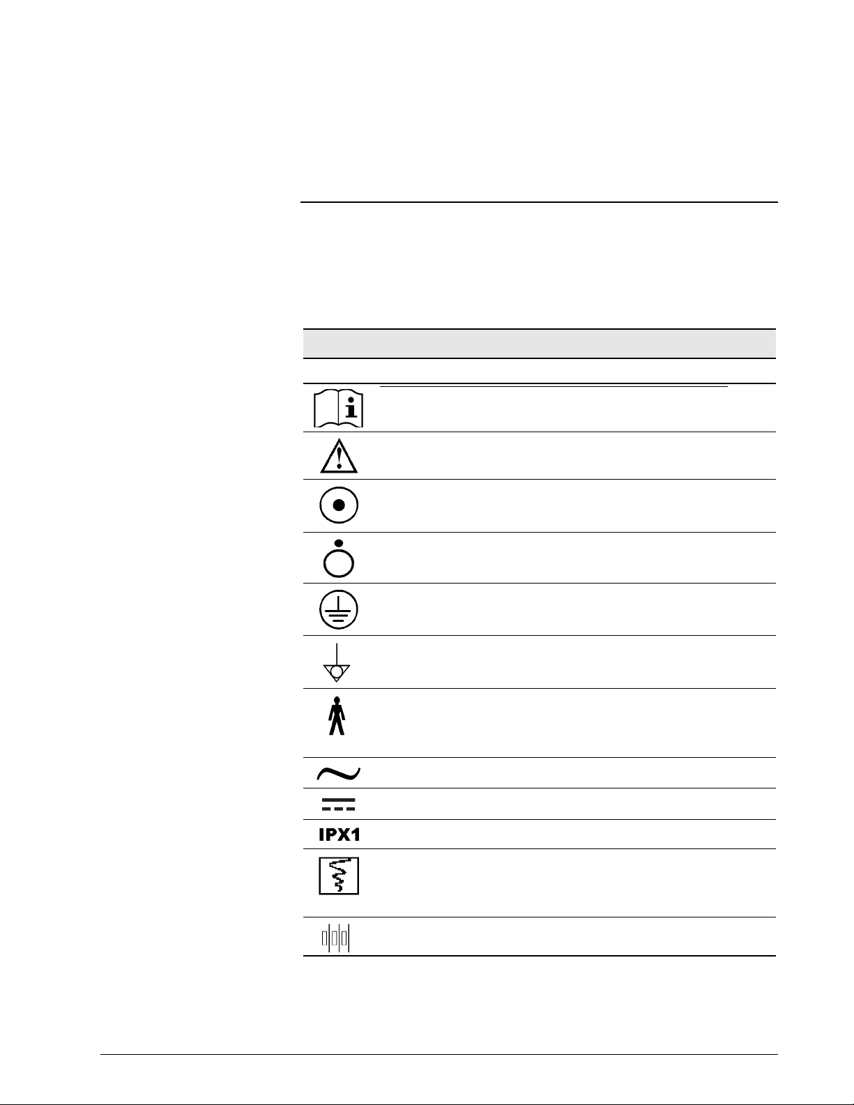
Chapter 3. Symbols
The following symbols appear on the Respironics V200 V entilator, accessories,
documentation, and packaging. Additional symbols pertaining to options and
accessories are included in the documentation for each option or accessory.
Refer to Chapter 13, “Options and Accessories”.
Symbol Description
Symbols
READ THE USER MANUAL OR ACCOMPANYING DOCUMENTS
ATTENTION
ON condition for part of the equipment. When pressed, the ventilator
will operate from the MAINS voltage if connected or from the backup
battery if the battery charge is within operating specifications.
OFF condition for part of the equipment
PROTECTIVE EARTH (ground)
POTENTIAL EQUALIZATION CONNECTOR used to connect the
equipment to an electrical installation earth busbar
TYPE B applied part, which indicates equipment that provides a
particular degree of protection against electric shock, particularly with
regards to allowable leakage current and of the protective earth
connection
SUITABLE FOR ALTERNATING CURRENT
DIRECT CURRENT
DRIP PROOF
Chart recorder ANALOG OUTPUT. Pin 12 signals an unsilenced high or
medium urgency alarm: 0 VDC= active alarm, 1.5 VDC = no alarm or
silenced alarm. (Voltage signal for flow and pressure reserved for futur e
use.)
DC BATTERY CONNECTION
Table 3-1: Symbols (Sheet 1 of 5)
REF 1057983 A Respironics V200 Ventilator Operator’s Manual 3-1
Page 24
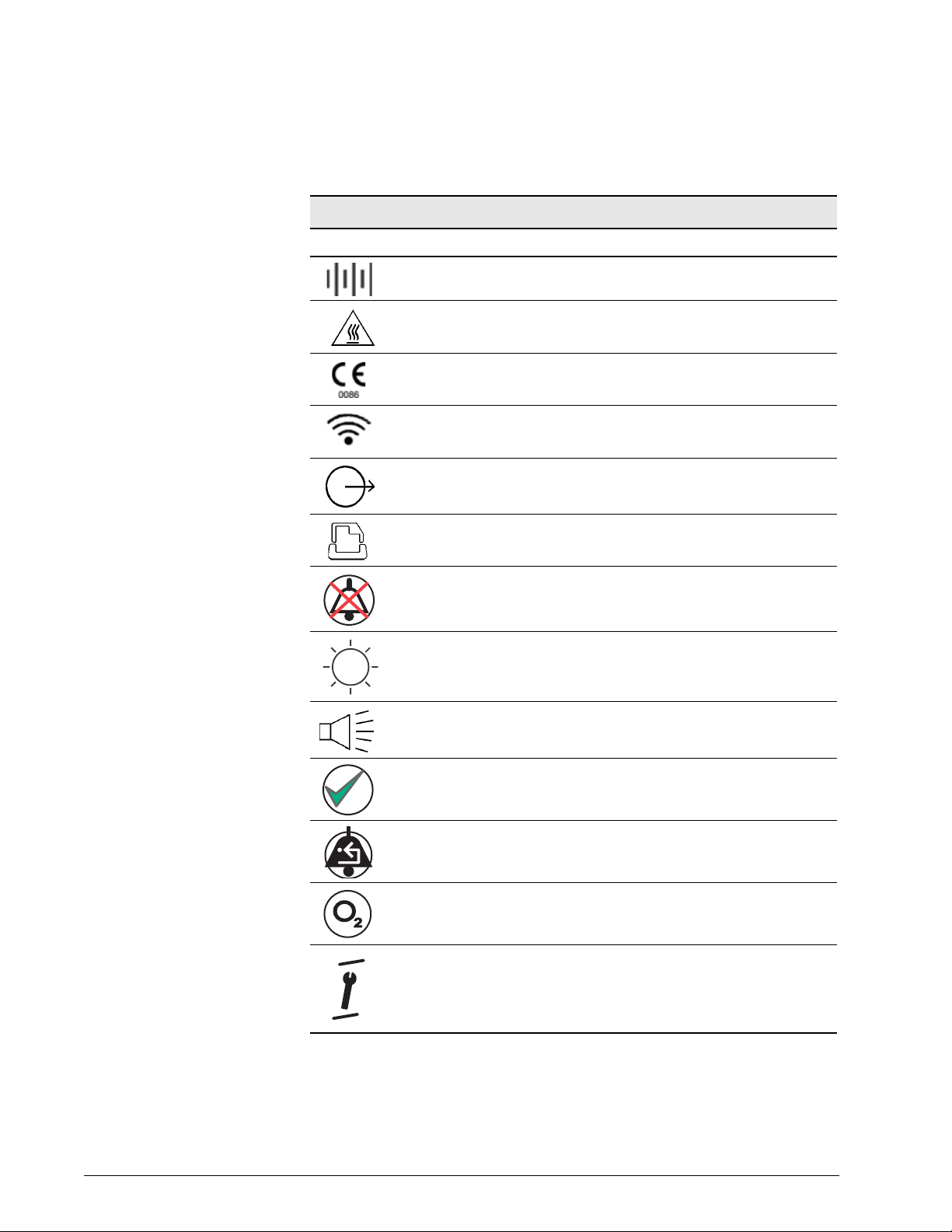
Chapter 3
Symbols
Symbols (Continued)
Symbol Description
DC BATTERY CONNECTION
HOT SURFACE warning
EUROPEAN CONFORMITY
REMOTE ALARM connection
RS-232 serial output
PARALLEL PORT printer connection
ALARM SILENCE (Silences alarm for two minutes)
BRIGHTNESS ADJUST
AUDIO ALARM VOLUME CONTROL
ACCEPT
ALARM RESET
100% OXYGEN
Located between the ALARM RESET and 100% O2 buttons, this
symbol indicates that the two keys (ALARM RESET AND 100% O
must be pressed simultaneously for approximately five seconds to enter
Diagnostic Mode
2)
Table 3-1: Symbols (Sheet 2 of 5)
3-2 Respironics V200 Ventilator Operator’s Manual REF 1057983 A
Page 25
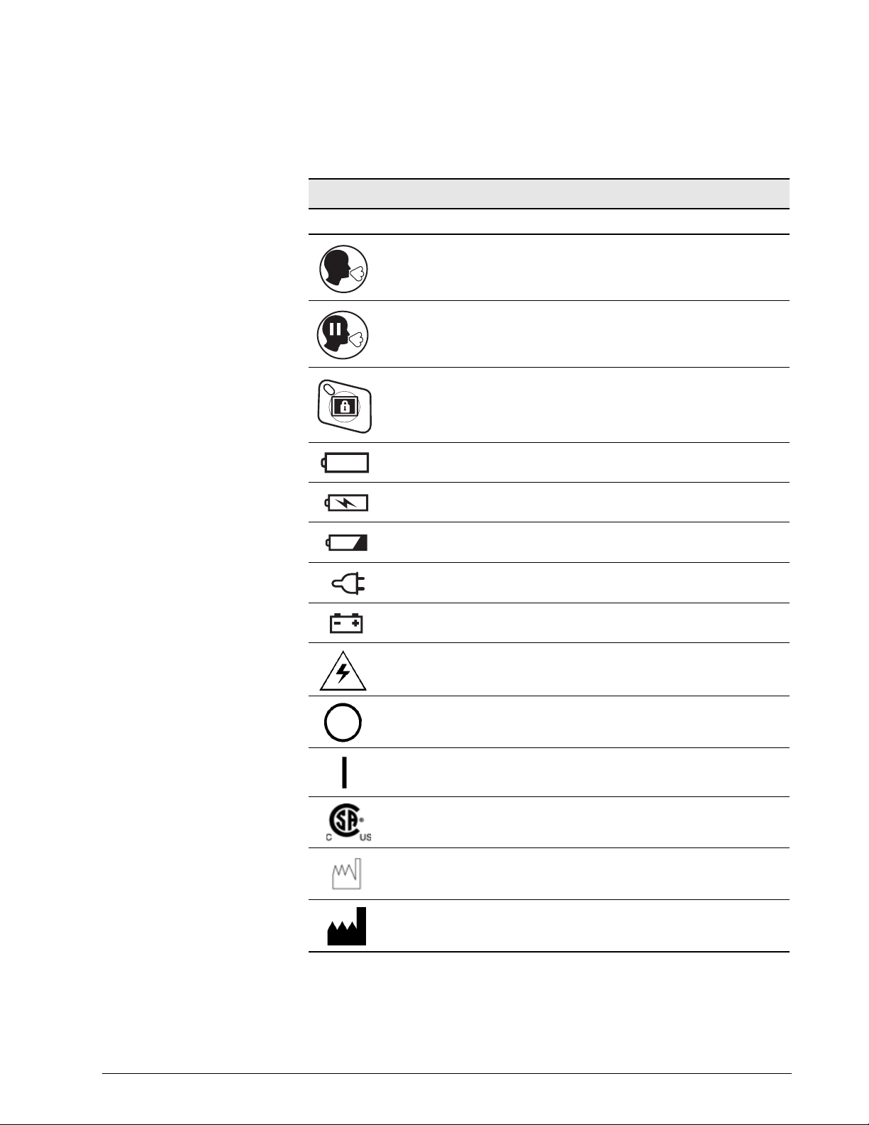
Symbol Description
MANUAL BREATH
EXPIRATORY HOLD
SCREEN LOCK
(Symbol version of the front panel only) Illuminates yellow to indicate
backup battery IN USE (backup)
Chapter 3
Symbols
Symbols (Continued)
(Symbol version of the front panel only) llluminates yellow to indicate
backup battery CHARGING
(Symbol version of the front panel only) Flashes red to indicate that the
backup battery is LOW
(Symbol version of the front panel only) MAINS battery indicator
(Symbol version of the front panel only) EXTERNAL BATTERY is in use
DANGEROUS VOLTAGE—electrical shock hazard
The portion of the circuit breaker that must be pushed in to turn the
CIRCUIT BREAKER OFF
The portion of the circuit breaker that must be pushed in to turn the
CIRCUIT BREAKER ON
CANADIAN STANDARDS ASSOCIATION approval.
DATE OF MANUFACTURE
MANUF ACTURER
Table 3-1: Symbols (Sheet 3 of 5)
REF 1057983 A Respironics V200 Ventilator Operator’s Manual 3-3
Page 26
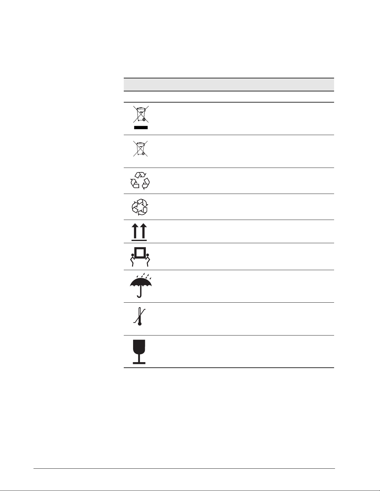
Chapter 3
Symbols
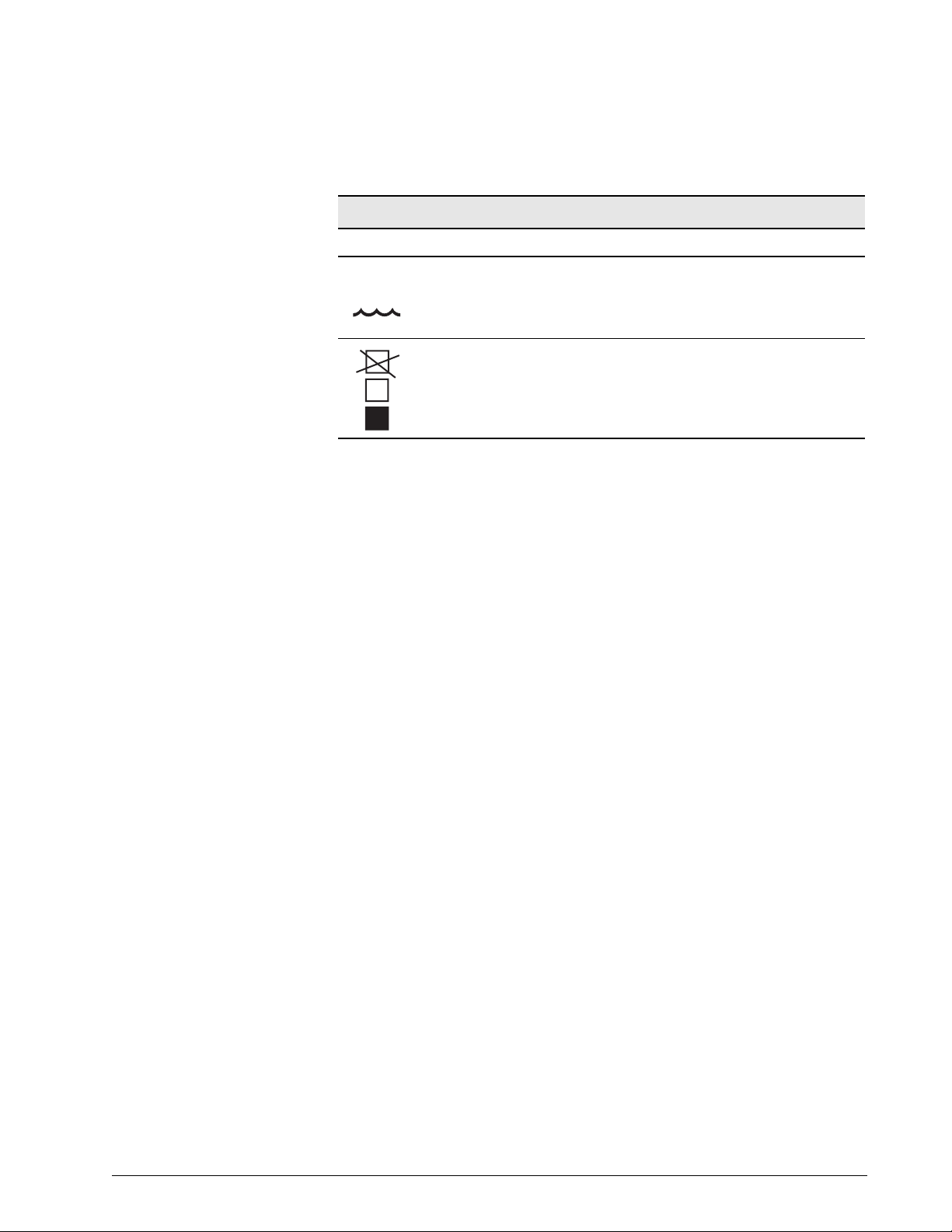
Symbol Description
The product must be disposed of in accordance with the WEEE
directive.
SEALED, NON-SPILLABLE LEAD ACID BATTERY. MUST BE
RECYCLED
Pb
SEALED, NON-SPILLABLE LEAD-ACID BATTERY. MUST BE
Pb
RECYCLED
RECYCLE
Symbols (Continued)
-20C
500-1060 hPa
THIS SIDE UP
AT LEAST TWO PEOPLE ARE REQUIRED TO LIFT THE VENTILATOR
TO AVOID POSSIBLE PERSONAL INJURY OR DAMAGE TO THE
EQUIPMENT.
KEEP DRY
LIMIT TEMPERATURE TO BETWEEN-20 AND 60 ºC (-4 AND 140 ºF)
+60C
FRAGILE
Table 3-1: Symbols (Sheet 4 of 5)
3-4 Respironics V200 Ventilator Operator’s Manual REF 1057983 A
Page 27
Symbol Description
STORE AT 10%-95% RELATIVE HUMIDITY
%
10-95
Do not stack > 2 high
2
Chapter 3
Symbols
Symbols (Continued)
Table 3-1: Symbols (Sheet 5 of 5)
REF 1057983 A Respironics V200 Ventilator Operator’s Manual 3-5
Page 28

Chapter 3
Symbols
(This page is intentionally blank.)
3-6 Respironics V200 Ventilator Operator’s Manual REF 1057983 A
Page 29
Chapter 4. Getting Started
Unpacking The Respironics V200 Ventilator has been carefully packaged to assure safe
shipping. In addition, the packing container has been designed for easy
unpacking. Do not discard packing materials.
Before unpacking the ventilator, examine the shipping carton(s) for visible
damage. If the shipping carton(s) arrives damaged or if you suspect the
contents are damaged, contact the carrier for an inspection report. If any
damage is evident, we recommend that you photograph the carton(s) before
the shipment is unpacked. Report any damage to the shi pping container or
ventilator to your local authorized Respironics distributor and to the carrier.
Save all packing material after removing the ventilator. In the event that the
ventilator or backup battery needs to be repacked and reshipped, use the
original packing material or order replacement material from a Respironics
representative.
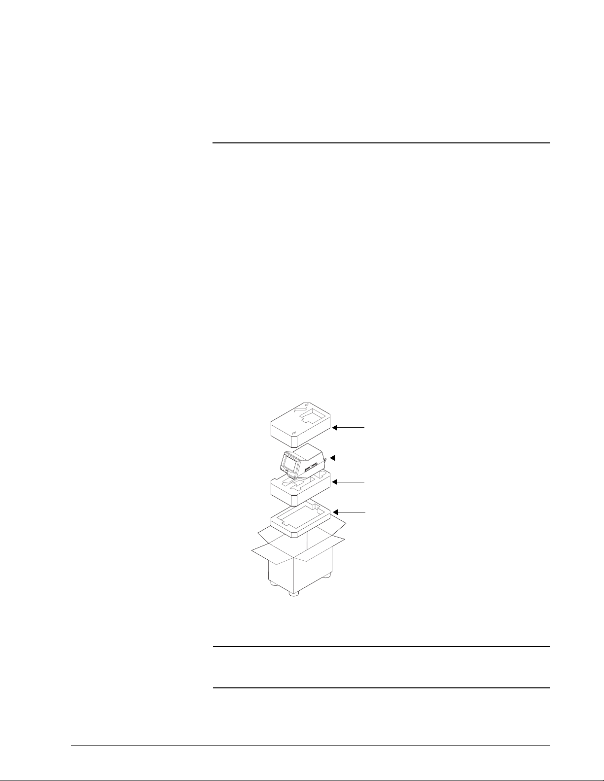
NOTE: The contents of the shipping carton may vary.
Top Foam Insert
Respironics V200 Ventilator
Center Foam Insert
Bottom Foam Insert
Figure 4-1: Unpacking/Repacking the Ventilator
WARNING: One person alone should not attempt to lift the ventilator or remove it from
the shipping carton or the cart. At least two people are required to avoid
possible personal injury or damage to the equipment.
REF 1057983 A Respironics V200 Ventilator Operator’s Manual 4-1
Page 30

Chapter 4
Getting Started
NOTE: Medical electrical equipment needs special precautions regarding EMC
and needs to be installed and put into service according to the EMC
information provided in Chapter 12, “Technical Specifications”.
Unpacking Instructions
Refer to Figure 4-1.
• Tools Required: Box knife
1. Using a box knife, cut a slit in packaging tape on top of shipping
carton.
2. Remove accessories box and optional flex arm box (not shown).
3. Remove top foam insert from inside carton.
4. Roll the plastic shipping bag (not shown) off the ventilator.
5. Gently lift ventilator from the bag and carton.
6. Remove patient circuit package (not shown).
7. Store carton, foam insert, and plastic bag in safe place for possible
future use.
Inspection After unpacking the ventilator, inspect its cabinet exterior for damage,
including cracks and scratches or blemishes. Inspect the front panel for
scratches, chips, abrasions or other deformities.
CAUTION: Be sure to check all exterior parts of the ventilator. Problems found
during inspection should be corrected and/or reported to Respironics
before using the ventilator.
List of Parts and Accessories
Using the packing list that accompanies the ventilator, take an inventory of the
entire shipment before assembling the ventilator. In case of discrepancies,
immediately contact Respironics Customer Service at 1-800-345-6443.
The Esprit/V200 Ventilator Service Manual, P/N 580-1000-02, is available for
qualified personnel. It includes block diagrams, components parts lists,
descriptions, calibration instructions, and ot her information that will assist
appropriately qualified personnel to repair those parts of the equipment that
are designated by the manufacturer as repairable. For more information
contact Respironics Customer Service at 1-800-345-6443.
4-2 Respironics V200 Ventilator Operator’s Manual REF 1057983 A
Page 31

Chapter 4
Getting Started
NOTE: We recommend that before using the ventilator for the first time, wipe
the exterior clean and disinfect or sterilize its components according to
the instructions in Chapter 10, “Care and Maintenance” or the
component manufacturer’s instructions.
Repacking Should the ventilator need to be returned to Respironics for servicing, or
shipped elsewhere for any reason, instructions for repacking are listed below.
The following instructions should be followed closely to avoid damage to the
ventilator.
WARNING: One person alone should not attempt to lift the ventilator or remove it from
the shipping carton or the cart. At least two people are required to avoid
possible personal injury or damage to the equipment.
CAUTION: Always ship the ventilator using the original packing material. If the
original material is not available, contact your Respironics
representative to order replacements.
Repacking Instructions
Refer to Figure 4-1.
• Tools Required: Heavy duty packaging tape
1. Open carton so that bottom foam insert is facing up.
2. Place backup battery in the bottom foam insert if it is being shipped.
3. Place center foam insert into box on top of the bottom foam insert.
4. If you are also shipping the flex arm, place it in its box (not shown)
and place the box in the bottom of the center foam insert.
5. Remove all power cords and accessory items from the ventilator.
6. Set the open ventilator shipping bag (not shown) in the box on the
middle foam insert.
7. Gently place the ventilator into the open bag. Check to ensure that the
ventilator is firmly positioned into bottom foam insert. Close plastic
bag over the ventilator.
8. Replace accessories box (not shown) in the center foam insert beside
the ventilator (if also being shipped).
9. Place top foam insert onto ventilator. Ensure snug fit.
10. Close top flaps of carton and seal with heavy-duty packaging tape.
REF 1057983 A Respironics V200 Ventilator Operator’s Manual 4-3
Page 32

Chapter 4
Getting Started
Ventilator Positioning For information about mounting the ventilator on a table top, see the Esprit
Operator’s Manual (580-1000-01).
If the ventilator is on a cart, lock the cart wheels as needed as shown in Figure
4-2.
Figure 4-2: Locking Ventilator Wheel
Backup Battery The ventilator will automatically switch to operating on backup battery power when
the AC power fails or the system is disconnected from AC mains power. A fully
charged backup battery will operate the ventilator for approximately 30 minutes,
dependent upon the specific ventilator setting.
WARNING: The batteries (backup battery) in the battery compartment are non-spillable
sealed lead acid. Recycle or dispose of batteries properly.
WARNING: Do not connect the DC power cord from the backup battery while the
Respironics V200 is functioning as a ventilator. Always turn the Po wer On/
Off switch to off ( ).
WARNING: Backup battery operating life may be affected by battery age and the number
of times it has been discharged and recharged. Over time the battery will
degenerate and will not provide the same amount of operating time per
charge that is available from a fully charged new battery. Use only the
Respironics backup battery P/ N 1059956.
4-4 Respironics V200 Ventilator Operator’s Manual REF 1057983 A
Page 33

Chapter 4
Getting Started
Backup Battery Removal and Installation
Required Tool: Philips screwdriver
Remove the backup battery from the internal packaging material and shipping
bag. Do not discard packing materials until the backup battery has been
installed on the ventilator and its operation has been confirmed.
NOTE: Save the shipping container in case the backup battery has to be returned
to Respironics.
Figure 4-3 illustrates the backup battery assembly.
Figure 4-3: Backup Battery
1. Before the backup battery is installed, disconnect AC power and any
attached equipment. Disconnect the backup battery cable connector
from the rear panel of the ventilator by rotating the connector's collar
nut counterclockwise while pulling back on the connector.
REF 1057983 A Respironics V200 Ventilator Operator’s Manual 4-5
Page 34

Chapter 4
Getting Started
Figure 4-4: Disconnecting the Battery Cable
2. Remove the rear cable channel cover from the cart by gently prying it
back from the top of the center column, freeing it from the column.
Rear cable channel cover
Figure 4-5: Removing the Rear Cable Channel Cover
4-6 Respironics V200 Ventilator Operator’s Manual REF 1057983 A
Page 35

Chapter 4
Getting Started
3. Loosen the ventilator mounting screws (4) from the underside of the
cart, and remove the ventilator from the cart.
WARNING: One person alone should not attempt to lift the ventilator or remove it from the
shipping carton or the cart. At least two people are required to avoid possible
personal injury or damage to the equipment.
Mounting screws
Figure 4-6: Removing the Ventilator from the Cart
REF 1057983 A Respironics V200 Ventilator Operator’s Manual 4-7
Page 36

Chapter 4
Getting Started
4. Remove the screws (4) holding the battery tray to the cart.
Battery tray
mounting screws
Figure 4-7: Removing the Battery Tray
5. Gently pull up the battery tray and remove it from the cart.
Figure 4-8: Removing the Battery Tray
4-8 Respironics V200 Ventilator Operator’s Manual REF 1057983 A
Page 37

Chapter 4
Getting Started
6. If a battery is present in the battery tray, disconnect the old battery
from the battery tray’s cable.
Figure 4-9: Disconnecting the Old Battery from the Battery Tray’s Cable
7. Undo the straps, remove the old battery if present, and place the new
battery in the battery tray.
Figure 4-10: Inserting Battery Into Tray
REF 1057983 A Respironics V200 Ventilator Operator’s Manual 4-9
Page 38

Chapter 4
Getting Started
8. Position the D ring on the straps as shown below.
NOTE: If the D rings are not positioned properly, the excess strap will interfere
with the tray’s channel guide.
Figure 4-11: Positioning the D Rings on the Battery Straps
9. Connect the battery to the battery tray’s cable.
Figure 4-12: Connecting the Battery to the Battery Tray’s Cable
10. Insert the battery tray into the cart’s center column by mating the
battery tray’s channel guide to the tray’s channel guide of the center
column.
CAUTION: When inserting the battery tray into the cart’s center column, make sure
not to crimp cable connections between the battery tray and cart.
4-10 Respironics V200 Ventilator Operator’s Manual REF 1057983 A
Page 39

Chapter 4
Getting Started
Figure 4-13: Installing the Battery Tray
11. Slide the battery halfway down the center column, and insert the
circular right angle battery connector into the cutout. Pull the cable
downward as the tray is fully inserted into the cart's center column.
Figure 4-14: Inserting the Circular Right Angle Battery Connector Into the Cutout
REF 1057983 A Respironics V200 Ventilator Operator’s Manual 4-11
Page 40

Chapter 4
Getting Started
12. Fasten the battery tray to the cart using the 4 screws used when the
tray was removed.
Battery tray
mounting screws
Figure 4-15: Battery Tray Mounting Screws
13. Set the ventilator back on the cart, ensuring that the four ventilator
feet meet the four circular recesses on the top of the cart. Tighten the
four mounting screws that were loosened in step 3 .
4-12 Respironics V200 Ventilator Operator’s Manual REF 1057983 A
Page 41

Chapter 4
Getting Started
14. Routing the backup battery cable from the tray between the rear of the
ventilator and the rear handle of the cart, connect the cable to the
circular battery connector on the back of the ventilator. Snap the rear
channel cover back into place.
Battery backup
connector
Figure 4-16: Backup Battery Connector
15. Plug the ventilator into an AC outlet.
16. Allow the backup battery to charge as required (see “Battery
Charging” on page 4-15).
17. When charging is complete, attach a patient circuit
and turn the
ventilator on in the diagnostics mode. Select the User Config touch
key and enable the Backup Battery confirmation feature (refer to
Chapter 5, “Backup Battery”).
18. Run SST (refer to Chapter 11, “Diagnostics”).
19. After SST has been successfully completed, exit the diagnostics mode
and power up the ventilator in the normal ventilation mode.
20. While the ventilator is cycling, unplug the AC power from the wall.
21. The ventilator should continue ventilation without interruption of any
kind.
22. The ventilator should have the “In Use” indicator (text version of front
panel) or the battery symbol (symbol version of the front panel)
on and a non-silenceable, non-resettable audible alarm should sound
every 60 seconds. "Backup Battery On" is displayed while the
ventilator consumes power from the backup battery.
23. Plug the AC wall power back in and the ventilator should continue
ventilation without interruption of any kind.
REF 1057983 A Respironics V200 Ventilator Operator’s Manual 4-13
Page 42

Chapter 4
Getting Started
Backup Battery Operation
When the backup battery is attached and the Respironics V200 Ventilator is operating in normal ventilation mode an ytim e there is a loss of AC power, the ventilator will automatically switch to battery pow er a nd c on tinue ventilation
without interruption. Whenever the ventilator is powered by th e backu p battery,
it will generate a non-silenceable, non-resettable alarm that creates an alarm
sound every 60 seconds. During this state, the front panel indicator labeled “In
Use” (text version of the front panel as shown in Figure 4-17), or the battery
symbol (symbol version of the front panel as shown in Figure 4-18) will
illuminate yellow continuously. In addition, "Backup Battery On" is displayed.
Figure 4-17: Backup Battery Front Panel Indicators — Text Version
Figure 4-18: Backup Battery Front Panel Indicators — Symbol Version
Operation will continue in this state until the battery capacit y is nearly ex pended. When the battery has only about 5 minutes of operation left, an audible,
nonresetable, HIGH priority alarm will sound. When this happens, the red,
front panel indicator labeled “Low” (text version of the front panel as shown in
Figure 4-17), or the low battery symbol (symbol version of the front panel as shown in Figure 4-18) and the high priority alarm LED will flash continuously. In addition, "Low Backup Battery" is displayed.
WARNING: When the battery low indicator is flashing red, operation of the ventilator
from the battery power should be discontinued.
When power is finally depleted, the ventilator will open the Safety Valve a nd
terminate ventilation in an orderly fashion. In this state, the front panel displays "Backup Battery Depleted-Connect AC & Cycle Power." The backup alarm
emits a continuous tone, the high priority alarm LED flashes, and the Safety
Valve, V ent Inop, and Battery Low front panel indicators remain lit until power
from the Backup Battery is completely gone.
Battery Capacity
There is a great deal of variability in the power consumption of the ventilator
depending on altitude, ventilator settings, and the age and amount of charge
on the backup battery. These parameters will determine the exact amount of
time the ventilator can operate from the backup battery.
4-14 Respironics V200 Ventilator Operator’s Manual REF 1057983 A
Page 43

Chapter 4
Getting Started
Battery Charging
When the ventilator is plugged into a viable AC supply, it will charge the
backup battery if the Mains Circuit Breaker is on and the machine is operating
as a ventilator, or in diagnostic mode or the Power ON/OFF switch is OFF
Charging time will depend on the amount of charge the batteries require. A
fully discharged backup battery will be fully recharged within 10 hours. If the
backup battery does not reach a full charge within 10 hours, contact
Respironics Customer Service. While the ventilator is charging, the front panel
indicator labeled “Charging” (text version of the front panel as shown in Figure
4-17) or the charging battery symbol (symbol version of the front panel
as shown in Figure 4-18) will be on continuously. When the backup battery is
fully charged, the indicator will turn off.
NOTE: For optimal performance and battery life of a newly purchased backup
battery, establish full backup battery charge by plugging the ventilator
into AC power for eight (8) hours maximum, or until the charging
indicator light turns off, and then unplug the unit.
( ).
NOTE: To monitor backup battery performance and life, run the ventilator on
battery power for at least 20 minutes at typical settings once a month.
Recharge the battery when the test is complete.
CAUTION: The backup battery is designed to be charged only by the Respironics
V200 Ventilator . Under no circumstances should an attempt be made to
charge it in any other way.
CAUTION: If the ventilator will not be used for 30 days or more, the backup battery
should be preserved. Either disconnect the backup battery from the
ventilator or keep the ventilator plugged into an active electrical outlet.
Warranty
Respironics warrants the backup battery to be free from defects in material
and workmanship for a period of one year from the date of purchase, provided
that the unit is operated under conditions of normal use as described in this
operator’s manual.
At its discretion, Respironics will make replacements, repairs or issue credits
for equipment or parts that are found to be defective.
REF 1057983 A Respironics V200 Ventilator Operator’s Manual 4-15
Page 44

Chapter 4
Getting Started
Inspiratory Bacteria Filter Installation
The inspiratory bacteria filter (4) in Figure 4-19, mounts on the gas outlet port
(1) located in the lower right corner on the front of the ventilator. If the
optional O
(1) before the inspiratory bacteria filter is connected. For more information
regarding the optional O
Accessories”.
sensor (2) will be used, it will be connected to the gas outlet port
2
sensor, refer to Chapter 13, “Options and
2
5
4
3
2
1
Flow
5
Figure 4-19: Inserting Disposable Inspiratory Bacteria Filter
4
3
2
1
4-16 Respironics V200 Ventilator Operator’s Manual REF 1057983 A
Page 45

Chapter 4
Getting Started
WARNING: To reduce the chance of contamination or infection, always use an
inspiratory and expiratory filter when the ventilator is in operation. Refer to
manufacturer’s instructions and follow institutional infection control
guidelines when replacing the inspiratory and expiratory filter.
WARNING: Do not use anti-static or conductive hoses or conductive patient tubing.
NOTE: Follow institutional infection control guidelines when replacing the
inspiratory or expiratory bacteria filter.
NOTE: When adding attachments or other components or subassemblies to the
breathing system, for example, an HME or humidifier, ensure that the
inspiratory and expiratory resistances (measured at the patient
connection port) do not exceed 6 cmH
adults, 30L/min for pediatrics.
Inspiratory Bacteria Filter Installation Instructions
Refer to Figure 4-19.
1. Locate the gas outlet port (1) on the front panel.
2. If the optional O
port (1).
3. Remove the inspiratory bacteria filter from the filter package and
inspect for cracks or potential leaks. Discard the filter if it is cracked,
has moisture inside, or is otherwise unserv iceable.
4. Some bacteria filters provide an arrow or other mark to indicate the
direction of flow. The flow indicator should be pointed away from the
ventilator, toward the patient circuit connection
Insert inspiratory filter inlet (4) into either
• the optional O
or
• the gas outlet port (1) if the optional O
5. Connect inspiratory limb of patient circuit (5) to bacteria filter (4).
sensor (2) will be used, connect it to the gas outlet
2
sensor (2) using the 22mm connector (3 )
2
O (hPa) at a flow of 60 L/min for
2
sensor (2) is not used.
2
REF 1057983 A Respironics V200 Ventilator Operator’s Manual 4-17
Page 46

Chapter 4
Getting Started
Heated Expiratory Bacteria Filter Installation
Figure 4-20: Installing Expiratory Bacteria Filter
WARNING: The expiratory filter housing may be hot if removed from the ventilator
immediately after use. Wait 15 minutes after turning off ventilator power
before removing the heated expiratory bacteria filter. Exercise caution when
handling the filter housing.
CAUTION: Do not operate the ventilator without a properly functioning expiratory
filter and heater. Doing so may cause damage to delicate ventilator
components, such as the expiratory flow sensor, which may lead to
inaccurate spirometry or a Vent Inop condition.
WARNING: Vent Inop is a serious condition, which is indicated by both visual and
audible alarms. If the ventilator is attached to a patient when Vent Inop
occurs, the patient must be supported with another means of life support
ventilation.
NOTE: Follow institutional infection control guidelines when replacing the
inspiratory or expiratory bacteria filter.
NOTE: When adding attachments or other components or subassemblies to the
breathing system, for example, an HME or humidifier, ensure that the
inspiratory and expiratory resistances (measured at the patient
connection port) do not exceed 6 cmH2O (hPa) at a flow of 60 L/min for
adults, 30L/min for pediatrics.
Heated Expiratory Bacteria Filter Installation Instructions
Refer to Figure 4-20.
4-18 Respironics V200 Ventilator Operator’s Manual REF 1057983 A
Page 47

Chapter 4
Getting Started
1. Locate the heated expiratory bacteria filter (1) and receiving
compartment (6) in the lower center of front panel.
2. Turn knob (2) counterclockwise to unlatch retaining bracket (3).
3. Open retaining bracket (3) by pulling it out and away from the
ventilator.
4. Use tabs (4) to gently pull the heater housing (5) away from the
ventilator.
5. Ensure that ventilator has been turned off for 15 minutes. If not, allow
the heater housing (5) to cool before touching it with fingers.
6. Gently remove the heater housing (5). Tap filter input port (7) if the
filter does not come out easily.
7. Insert the new expiratory bacteria filter (1) into the heater housing (5).
8. Reinstall housing (5) and filter (1) into receiving com partment (6),
then close retaining bracket (3).
9. Ensure that the retaining bracket (3) is securely closed and turn knob
(2) clockwise to secure latch.
10. Connect the exhalation limb and water collection system of the patient
circuit (not shown) to the inlet port of the exhalation filter (7).
NOTE: High humidity and aerosol medications may reduce expiratory filter life,
increase expiratory resistance, and/or cause filter damage. Review
ventilator patient graphics frequently for changes in expiratory resistance.
Consult filter manufacturer recommendations regarding duration of use,
maintenance, and removal and disposal of expiratory filter.
REF 1057983 A Respironics V200 Ventilator Operator’s Manual 4-19
Page 48

Chapter 4
Getting Started
Oxygen Source Connection
Figure 4-21: O2 Gas Connections and Filter
WARNING: All oxygen connections should be carefully inspected to ensure that leaks
are not present. Excessive leaks can result in higher than normal ambient
oxygen concentrations and create a potentially hazardous oxygen-enriched
environment.
WARNING: Worn/frayed oxygen hoses or oxygen hoses contaminated by hydrocarbon
greases or oils should not be used since an oxygen leak or intense fire
could result.
WARNING: Care in the routing of the oxygen inlet hose should be exercised to ensure it
is not exposed to mechanisms that could cause damage by cutting or
heating/melting.
CAUTION: The ventilator oxygen filter should be replaced annually as a part of
preventive maintenance.
NOTE: The ventilator should only be connected to an appropriate medical
grade 100% O
PSIG (276-620 kPa).
NOTE: The ventilator is shipped with the appropriate gas fittings and hoses for
the intended environment, i.e. DISS (U.S.A. and Canada), Ohmeda
(Germany), NIST (UK), Air Liquide (France), SIS (Australia).
gas source capable of delivering a regulated 40 to 90
2
4-20 Respironics V200 Ventilator Operator’s Manual REF 1057983 A
Page 49

Getting Started
Oxygen Source Connection Instructions
Refer to Figure 4-21.
1. Locate the O
of the rear panel.
2. Ensure that the O
the ventilator. Inspect the bowl (1) for cracks or potential leaks.
Ensure all connections are tight.
3. Inspect the O
mate (4).
4. Check the oxygen gas supply. Clean, adjust pressure, and drain
condensate from any water traps, filters, or regulators in the O
lines.
5. Connect O
connector (4).
6. If gas source is not already turned on, turn it on and verify that no O
gas is leaking.
filter with water trap (1) located in the lower left corner
2
filter and water trap (1) are properly attached to
2
hose (2), hose connector (3) and the hose connector
2
gas connector (3) to the ventilator O2 filter with DISS hose
2
Chapter 4
supply
2
2
REF 1057983 A Respironics V200 Ventilator Operator’s Manual 4-21
Page 50

Chapter 4
Getting Started
Patient Circuit Flex Arm Installation
A patient circuit flex arm is provided for use on the ventilator. The patient
circuit flex arm may be installed on either the left or right side rail on the cart.
3
1
2
5
4
Figure 4-22: Patient Circuit Flex Arm Installation
Patient Circuit Flex Arm Installation Instructions
Refer to Figure 4-22.
1. Slide flex arm bracket (1) on to the side rail of the cart (one per side).
2. Tighten black screw knob (2) on flex arm bracket.
3. Insert base of flex arm (3) into flex arm bracket and tighten.
4. Place patient circuit hose clamp (4) into the flex arm clamp (5) and
tighten.
4-22 Respironics V200 Ventilator Operator’s Manual REF 1057983 A
Page 51

Chapter 5. Setup
C
Back Panel Connections and Controls
1.RS-232
Serial Port
2. Remote
Alarm Nurse
Call
3. Parallel
Printer Port
4. PCMCIA
Card Slot
5. Analog Port
6. DC Battery
Connector
17. Cooling
Fan
Inlet
16. Potential
Equalization
Connection
15. O
Inlet
2
Filter and
Water Trap
14. O
Inlet
2
Connector
13. Elapsed
Time Meter
1. 232 Serial Port: Connection source for devices capable of serial
2. Remote Alarm Nurse Call: Connection source for remote alarm devices.
3. Parallel Printer Port: For use with the Communications Option. Refer to
4. PCMCIA Card Slot: (PC Card) For use with the T rending Option. Refer to
7. AC Inlet
8 Humidifier A
Circuit Breaker
9. Circuit
Breaker
Cover
(not shown)
10. Mains
Circuit
Breaker
11. Humidifier
AC Outlet
12. Air Inlet
Duct and Filter
Figure 5-1: Back Panel
communication. Refer to Chapter 6, “Connecting Additional
Equipment”.
Chapter 13, “Options and Accessories”.
Chapter 13, “Options and Accessories”.
REF 1057983 A Respironics V200 Ventilator Operator’s Manual 5-1
Page 52

Chapter 5
Setup
WARNING: The cover plate for the PCMCIA slot at the back of the ventilator must be
replaced after the adapter and card are installed. This is to protect the
ventilator.
CAUTION: The PCMCIA card should only be removed by trained service personnel
once power to the ventilator is off.
5. Analog Port: Pin 12 signals an unsilenced high or medium urgency
alarm. Other pins are used by the Communications Option. Refer to
Chapter 13, “Options and Accessories”.
6. DC Battery Connector: Connection source for battery power cord.
7. AC Inlet: Connection for AC power cord.
8. Humidifier AC Circuit Breaker: Circuit breaker for AC power applied to a
humidifier.
WARNING: AC power is applied to the humidifier from the ventilator humidifier outlet
(only available on 100-120 VAC ventilators). Under no circumstances does
the Respironics V200 Ventilator provide control for the humidifier . T o ensure
patient safety, it is important that any humidifier used with the ventilator
include an acceptable temperature control and monitoring mechanism, as
well as a temperature display and appropriate alarm capabilities (refer to
ISO 8185).
CAUTION: To avoid the possibility of damage to the ventilator, do not connect a
humidifier whose maximum rating exceeds 3 amps. Ensure that the
humidifier power cord is free from defects and any obvious wear , and is
properly grounded. A humidifier connection is only available on 100120VAC ventilators.
9. Circuit Breaker Cover: Circuit breaker cover (not shown) protects the
Humidifier AC Circuit Breaker and Mains Circuit Breaker switches.
10. Mains Circuit Breaker: Circuit breaker for main AC circuit.
11. Humidifier AC Outlet: Connection for Humidifier AC power cord.
12. Air Inlet Duct and Filter: Filters room air drawn into the ventilator
internal air source.
13. Elapsed Time Meter: Records time when the Power On/Off Switch is on
().
14. O
Inlet Connector: Connection for oxygen hoses.
2
15. O
Inlet Filter and Water Trap: Filters oxygen entering the ventilator.
2
16. Potential Equalization Connection: Common grounding point.
17. Cooling Fan Inlet: Allows cooling air to enter the ventilator.
5-2 Respironics V200 Ventilator Operator’s Manual REF 1057983 A
Page 53

Chapter 5
Setup
NOTE: All volumes entered into the ventilator are assumed to be BTPS (Body
Temperature atmospheric Pressure Saturated (with H2O)) volumes
unless otherwise noted. All volumes reported by the ventilator are
reported as BTPS volumes. All pressures are assumed to be relative to
atmospheric pressure unless otherwise noted.
Connecting AC Power Cord
NOTE:
The Air Inlet Filter houses a reusable foam filter that should be
periodically cleaned. Refer to Chapter 10, “Care and
Maintenance”, for more information on filter changes.
2
3
1
Circuit Breaker
Cover not shown.
Figure 5-2: AC Power Cord Retaining Bracket
WARNING: To avoid electrical shock hazard, connect the ventilator to a properly
grounded AC power outlet.
CAUTION: Before connecting the ventilator to the AC power source, ensure that the
total electrical load does not exceed the ampere rating of the AC branch
circuit, especially when using the ventilator with other electrical
equipment. An AC branch circuit includes all outlets serviced by a
single circuit breaker. If the maximum current drain through a branch
circuit exceeds the circuit breaker’s rating, the branch circuit will open,
causing the ventilator to lose power. For further information, consult a
service technician or a trained biomedical technician.
CAUTION: The ventilator is shipped with a power cord that complies with electrical
safety standards. Do not use substitute power cords unless specifically
instructed to do so by an authorized distributor or qualified personnel.
Do not modify the power cord or connect it with electrical extension
cords or outlet adapters.
REF 1057983 A Respironics V200 Ventilator Operator’s Manual 5-3
Page 54

Chapter 5
Setup
Connecting AC Power Cord Instructions
Refer to Figure 5-2.
• Tools Required: Small Phillips screwdriver
1. Ensure that the ventilator is properly positioned on a secure table top,
wall mount, or pedestal.
2. Connect the AC Power Cord (1) to the AC inlet (3) located on the rear
panel. (Refer to Figure 5-1.)
3. After cord is fully inserted, tighten the retaining bracket screw (2) so
that the power cord cannot be inadvertently disconnected from the
ventilator.
Power On/Off The ON/OFF ( / ) switch is located in the lower portion of the front panel,
and is recessed to avoid inadvertent access.
When the switch is in OFF ( ) position, the ventilato r does not provide
mechanical ventilation. If the AC plug is connected and the Mains circuit
breaker (refer to Figure 5-1) is ON ( ), AC power is active and the green
Mains circuit indicator on the front panel, is illuminated.
Vent
Inop
Safety
Valve
Power On/
Off Switch
Figure 5-3: On/Off Switch
5-4 Respironics V200 Ventilator Operator’s Manual REF 1057983 A
Page 55

Chapter 5
Setup
Turning the Ventilator On
1. Ensure that the Mains Circuit Breaker (refer to Figure 5-1), located on
the ventilator back panel, is in the ON ( ) position.
2. For 120V applications, if a humidifier is attached to the ven tilator,
ensure that the Humidifier AC Circuit Breaker (refer to Figure 5-1),
located on the ventilator back panel, is in the ON ( ) position. A
humidifier connection is only available on 100-120VAC ventilators.
3. Press the Power ON/OFF switch to the ON ( ) position (left side up).
WARNING: The ventilator front panel LEDs will indicate the power source that is being
used. If the ventilator is plugged in and the MAINS LED is not lit, either the
circuit breaker is off or the wall power outlet is not functioning.
Turning the Ventilator Off
1. Press the Power ON/OFF Switch to the OFF ( ) position (right side
up).
Entering Diagnostic Mode
WARNING: The two circuit breakers (MAINS/Humidifier) located on the back of the
ventilator are covered to prevent unintentional ventilator power-off. Do not
use the circuit breaker to power the ventilator on/off. The power switch is
located on the front of the ventilator below the front panel.
NOTE: Unless the Mains Circuit Breaker is turned OFF, electrical power is
applied to the ventilator even though the front panel switch is in the
OFF position. With the Mains Circuit Breaker ON, if the backup battery
is connected, the ventilator will charge the battery if it requires a
charge.
NOTE: To disconnect the ventilator from MAINS power, remove the AC plug
from the wall power receptacle. The MAIN switch/circuit breaker is
covered to prevent unintentional ventilator turn off.
The Diagnostic Mode is used for:
1. Running tests of the operation of the ventilator that can only be run
when a patient is not attached to the machine.
2. Setting altitude, time and date, and circuit compliance.
3. Other more detailed service/maintenance functions.
4. Calibration of inline Oxygen Sensor, during EST only.
Some of these functions are discussed in detail in Chapter 12, “Technical
Specifications”. The functions of the Diagnostic Mode that are used to make
the machine ready for use as a ventilator when it is first put into service are
explained here.
REF 1057983 A Respironics V200 Ventilator Operator’s Manual 5-5
Page 56

Chapter 5
Setup
Entering Diagnostic Mode
1. To access the Diagnostic Mode, simultaneously press the ALARM
RESET and 100% O
seconds while turning the ventilator power on. The following message
will appear on the screen:
Figure 5-4: Warning in Diagnostic Mode
2. Press the OK button to enter the Diagnostic Mode. The following
screen appears:
keys on the front panel for approximately five
2
Figure 5-5: Main Screen in Diagnostic Mode
5-6 Respironics V200 Ventilator Operator’s Manual REF 1057983 A
Page 57

Chapter 5
Setup
User Configuration Screen
The buttons across the top and bottom bars are used to select the Diagnostic
Mode functions. To set up the machine for the first time for operation as a
ventilator, USER CONFIG should be selected. When this button is pressed, the
following screen appears.
Figure 5-6: User Configuration Screen
The User Configuration screen allows the operator to:
• Set the date and time
• Activate or deactivate the automatic patient circuit compliance
compensation feature
• Set the proper altitude
• Set 24 Hrs/AM PM time display
• Activate or deactivate backup battery check at startup
Date and Time
The real-time clock and calendar will last for approximately 2.5 years. When
the ventilator is received, the clock’s time will have to be changed to that of
the existing time zone. The date should be checked and changed if necessary.
Setting Date and Time Format
To set time (Figure 5-8) or date (Figure 5-7):
1. Press the desired date or time button (month, day, year, hour, minute,
second).
2. When the window insert appears, press the INCREASE or DECREASE
button, or rotate the control knob to change the value of the selected
parameter.
REF 1057983 A Respironics V200 Ventilator Operator’s Manual 5-7
Page 58

Chapter 5
Setup
3. Press the ACCEPT butt on to confirm the change and return to the User
Config screen. Press the CANCEL button to leave the value
unchanged.
Window insert
to change the
value of Month
Figure 5-7: Setting the Date
Window insert
to change the
value of Hour
Figure 5-8: Setting the Time
4. After the date and time values have been set, the changes will be
shown on the screen.
5. Press the APPLY DATE and APPLY TIME buttons to activate the
change.
5-8 Respironics V200 Ventilator Operator’s Manual REF 1057983 A
Page 59

Apply Date
button
Apply Time
button
Figure 5-9: User Configuration Screen After Date and Time are Set
Chapter 5
Setup
6. The 24 HR CLOCK button allows the operator or technician to set the
displayed time in an AM/PM (e.g., 1:15 PM) or 24 Hr. (e.g., 13:15)
format. When the 24 HR CLOCK button has a white background, time
is displayed in the 24 Hr. format; when it has a gray background, time
is displayed in the AM/PM format.
7. Press the 24 HR CLOCK button to toggle between AM/PM and 24 Hr.
formats. Observe the time display in the lower right hand corner of the
diagnostic screen to confirm the format.
Altitude
The User Configuration screen in the Diagnostic Mode is used to input the
altitude of the location of the ventilator. To enter Diagnostic Mode, follow th e
instructions “Entering Diagnostic Mode” on page 5-6. At Figure 5-5 select
USER CONFIG and the screen in Figure 5-10 appears. Pressing the ALTITUDE
button enables you to set the altitude to that of the present geographical
location of the ventilator. This factor ensures a more accurate tidal volume
delivery.
Setting Altitude
To adjust the altitude:
1. Verify the altitude using an altimeter, if available , or estimate the
altitude in feet (or meters) above sea level.
2. Press the ALTITUDE button.
3. When the window insert appears, select either feet or meters. Press
the INCREASE or DECREASE button, or rotate the control knob, to
change the value. The longer the increase and decrease are touched,
the faster the value will change.
REF 1057983 A Respironics V200 Ventilator Operator’s Manual 5-9
Page 60

Chapter 5
Setup
4. Press ACCEPT to accept the changed value. Press the CANCEL button
to leave the value unchanged.
Window insert
to change the
value of Altitude
Figure 5-10: Setting Altitude
Enabling/Disabling Tubing Compliance
The operator can activate or deactivate “tubing compliance compensation” in
the User Configuration screen. To enter Diagnostic Mode, follow the
instructions for “Entering Diagnostic Mode” on page 5-6. At Figure 5-5, select
USER CONFIG and the screen in Figure 5-11 appears.
Figure 5-11: Compliance Activated
5-10 Respironics V200 Ventilator Operator’s Manual REF 1057983 A
Page 61

Chapter 5
Setup
You can have the ventilator compensate the volumes delivered in volume
controlled, mandatory breaths with the tubing compliance volume by
activating the COMPLIANCE button (Figure 5-11). Circuit compliance is
activated when this button has a white background. When the function is
activated the exhaled volumes reported by the ventilator will also be tubing
compliance compensated.
Backup Battery You can have the ventilator confirm the backup battery is connected each time
that the machine powers on. Pressing the BKUP BATTERY button (Figure 5-
12) allows this confirmation feature, which is identified by an active button
with a white background.
Backup Battery
(confirm at
startup)
button active
Figure 5-12: Backup Battery Activated
From then on when the machine powers on, it searches for a backup battery . If
the backup battery is connected to the ventilator, the startup is normal. If the
backup battery is not connected, the ventilator displays a message at startup
and a 5002 Diagnostic Code will be logged.
Figure 5-13: No Backup Battery Connected message
REF 1057983 A Respironics V200 Ventilator Operator’s Manual 5-11
Page 62

Chapter 5
Setup
Press the OK button to clear the message from the screen. You may continue
to use the ventilator without the backup battery or power off the ventilator and
reconnect the backup battery.
WARNING: Always turn the ventilator power OFF before connecting additional
equipment.
To turn this feature off, enter Diagno stic Mode and deactivate the messaging
feature by pressing the BKUP BATTERY button.
1. Power off the ventilator.
2. Power on the ventilator while holding down the ALARM RESET and
100% O
3. A message appears on the ventilator screen asking the user to ‘Verify
that the patient is disconnected prior to proceeding.’ Press OK to enter
Diagnostic Mode.
4. Once you’ve entered Diagnostic Mode, select USER CONFIG button,
which takes you to the User Config screen.
5. Press the BKUP BATTERY button. The background color should return
to blue signifying that this feature has been deactivated.
keys simultaneously for approximately 5 seconds.
2
Extended Self Test (EST)
We recommend that you run an Extended Self Test (EST) upon receipt of the
ventilator to ensure that there has been no shipping damage to the system. We
also recommend that you run EST betwee n patients to verify the overall
functional integrity of the ventilator. Refer to chapter 11 for instructions on
running EST.
If EST was run successfully and all configuration information has been
entered, the ventilator is ready to be used. Follow the recommended
“Preoperational Procedure” on page 8-32 once a patient has been selected.
To exit the Diagnostics Mode you must turn the Power On/Off switch OFF ( )
and then turn it ON ( ).
5-12 Respironics V200 Ventilator Operator’s Manual REF 1057983 A
Page 63

Chapter 6. Connecting Additional Equipment
Communication Interface
WARNING: Always turn the ventilator power OFF before connecting additional
equipment.
CAUTION: T o prevent the risk of excessive leakage due to external equipment being
connected to the ventilator via the communication ports, a means for
external separation of the conductive earth paths must be provided.
CAUTION: All equipment used and connected to the ventilator communications
ports (analog, parallel, and serial) must comply with the medical
electrical equipment (IEC601-1) or other applicable standards.
The ventilator provides three communications interfaces: one serial RS-232
port, an analog output port, and a parallel port. (The parallel port is reserved
for use by the Communications Option.)
Remote Alarm
Serial
AnalogParallel
AC Power Cord
Circuit Breaker
(cover not shown)
Humidifier AC
Outlet
Figure 6-1: Ports and Outlets on the Rear Panel
REF 1057983 A Respironics V200 Ventilator Operator’s Manual 6-1
Page 64

Chapter 6
Connecting Additional Equipment
Connecting Serial Communications Devices
Connecting Remote Alarm Port
The serial port is designed to transmit data on a one device to one device serial
communications channel. In the connection between the two devices, the
ventilator assumes the “slave” role and responds to commands transmitted to
it via the serial port by the external “master.” The serial communications port
uses a standard RS-232, null modem, pin configuration. The ventilator
assumes the serial communications is set up for:
• 19,200 bits/second baud rate
• 8 data bits
• no parity bit
• 1 stop bit
The ventilator is sent commands that are 4 ASCII characters from the external
device and responds with a fixed format message. The commands and the
responses are specified in Appendix A, “RS-232 Communications Protocol”.
The ventilator is equipped with a remote alarm port enabling ventilator alarm
conditions to be sounded at remote locations away from the ventilator.
Pressing ALARM SILENCE deactivates the remote alarm. The ventilator signals
an alarm using a normally open or normally closed relay contact. The deenergized state of the relay represents an alarm state (any Medium or High
Priority alarm) and the energized state represents no alarms.
The remote alarm port is a standard ¼ inch, female, phono jack (ring, tip,
sleeve) connector.
Remote alarm
RingNO
TipNC
SleeveCommon
Figure 6-2: Remote Alarm Port
The port is configured to work with the Normally Open (NO), Normally Closed
(NC), and Respironics (LifeCare) systems. Each requires specific cabling
identified in Table 6-1:.
connector & cable
6-2 Respironics V200 Ventilator Operator’s Manual REF 1057983 A
Page 65

Chapter 6
Connecting Additional Equipment
Remote Alarm Cable Kits
System Part Number
Remote Alarm Cable Kit (Normally Open Protocol) 1003741
Remote Alarm Cable Kit (Normally Closed Protocol) 1003742
Remote Alarm Cable Kit — Respironics (LifeCare) 1003743
Table 6-1: Remote Alarm Cable Kits
WARNING: Use only Respironics approved cables when connecting to the remote alarm
port. Be sure to fully insert the cable into the remote alarm port and into the
remote alarm.
WARNING: When using the Remote Alarm Port, be sure to fully test the Remote Alarm
Port and cable by:
• Verifying that annunciated alarms on the ventilator are also
annunciated on the remote alarm.
• Verifying that disconnecting the cable from the Remote Alarm port
results in an alarm notification at the Remote Alarm.
• Verifying that disconnecting the cable from the remote alarm
results in an alarm notification at the Remote Alarm.
Connecting Humidifier
CAUTION: The remote alarm port is intended to connect only to SELV (safety extra
low voltage and ungrounded system with basic insulation to ground), in
accordance with IEC60601-1. To prevent damage to the remote alarm,
the signal input should not exceed the maximum rating of 24 VAC or 36
VDC at 500 mA with a minimum current of 1 mA.
We recommend only those humidifiers that comply with ISO 8185 fo r use on
the ventilator.
You should consult with the manufacturer(s) of the active humidification
system (humidifier and patient circuit components) for their most recent
recommendations regarding circuit configurations. Additionally, unless
specifically contraindicated by th es e manufacturers’ recommendations, we
recommend the use of a drop-down tube and water collection vial (water trap)
placed between the expiratory filter and the expiratory limb of the patient
circuit. This is necessary to prevent damage to the expiratory filter. Refe rence
P/N 1006241 Water Collection System, or equivalent.
CAUTION: Failure to protect the expiratory filter from damage by using inappropriate
patient circuit configurations may cause damage to delicate ventilator
components, such as the expiratory flow sensor , which may lead to
inaccurate spirometry or a Vent Inop condition.
REF 1057983 A Respironics V200 Ventilator Operator’s Manual 6-3
Page 66

Chapter 6
Connecting Additional Equipment
WARNING: Vent Inop is a serious condition, which is indicated by both visua l and audible
When connecting a humidifier to the patient circuit, follow the setup
procedure supplied by the humidifier manufacturer . The following steps should
be followed to electrically connect the humidifier to the ventilator (for 100120 VAC ventilators). For ventilators using voltage other than 100-120 VAC,
the humidifier must be connected to another AC outlet.
alarms. If the ventilator is attached to a patient when Vent Inop occurs, the
patient must be supported with another means of life support ventilation.
1. Remove the cover of the humidifier AC power outlet on the back of the
ventilator (Figure 6-3).
(Circuit Breaker Cover
not shown)
Humidifier AC Outlet
Cover
Figure 6-3: Humidifier AC Outlet Cover
2. Connect the humidifier AC plug to the humidifier AC power outlet.
(Circuit Breaker Cover
not shown)
Humidifier AC Plug
Figure 6-4: Humidifier AC Plug
6-4 Respironics V200 Ventilator Operator’s Manual REF 1057983 A
Page 67

Chapter 6
Connecting Additional Equipment
3. Run any test procedures recommended by the h umidifier
manufacturer before the ventilator and humidifier are used on a
patient.
WARNING: AC power is applied to the humidifier from the ventilator humidifier outlet
(only available on 100-120 VAC ventilators). Under no circumstances does
the Respironics V200 Ventilator provide control for the humidifier . T o ensure
patient safety, it is important that any humidifier used with the ventilator
include an acceptable temperature control and monitoring mechanism, as
well as a temperature display and appropriate alarm capabilities (refer to
ISO 8185).
Connecting the Patient Circuit
1. The humidifier should be connected between the inspiratory bacteria
filter (Figure 6-5) and the inspiratory limb of the patient circuit that
leads to the patient wye (Figure 6-6).
2. Follow steps illustrated by Figure 6-5, Figure 6-6, and Figure 6-7.
Figure 6-5: Ventilator Gas Outlet Port to Humidifier Patient Circuit Connection
REF 1057983 A Respironics V200 Ventilator Operator’s Manual 6-5
Page 68

Chapter 6
Connecting Additional Equipment
Figure 6-6: Humidifier Outlet to Patient Wye Connection
Figure 6-7: Expiratory Limb of Patient Circuit to Water Trap Connection (Shows Down
Tube between Ventilator and Water Trap)
6-6 Respironics V200 Ventilator Operator’s Manual REF 1057983 A
Page 69

Chapter 6
Connecting Additional Equipment
When connecting a patient circuit without a humidifier (for example, when
using a heat and moisture exchanger), refer to Figure 6-8.
Connecting the Analog Port
Figure 6-8: Patient Circuit Connections Without Humidifier
The analog output port adds a second remote alarm output. Pin 12 (fourth pin
from the top left is pin 12) signals an unsilenced high or medium urgency
alarm:
• 0 VDC = active alarm
• 1.5 VDC = no alarm or silenced alarm
REF 1057983 A Respironics V200 Ventilator Operator’s Manual 6-7
Page 70

Chapter 6
Connecting Additional Equipment
The Communications option provides additional signals on this port. Refer to
Chapter 13, “Options and Accessories”.
Analog
Port
(Circuit
breaker cover
not shown)
Figure 6-9: Analog Port
6-8 Respironics V200 Ventilator Operator’s Manual REF 1057983 A
Page 71

Chapter 7. Operating Theory
Introduction This chapter describes the ventilator’s breath delivery capabilities. It includes
a system overview and descriptions of the ventilation modes and available
breath types. For descriptions of button settings and general operating
instructions, refer to Chapter 8, “Operating Instructions”.
System Overview The ventilator is a microprocessor-controlled ventilator capable of delivering a
mixture of air and oxygen to a patient’s lungs in a predetermined manner to
augment or replace the work normally performed by the patient’s respiratory
system. The ventilator performs breath delivery via two different patient
interfaces:
• endotracheal tube or tracheostomy tube (invasive ventilation)
• face mask, nasal mask, nasal pillows, or mouthpiece with a seal (non-
invasive ventilation)
Ventilator Breath Types
The ventilator provides the following ventilation breath types:
• Volume Control Ventilation (VCV) – invasive ventilation
• Pressure Control Ventilation (PCV) – invasive ventilation
• Non-Invasive Positive Pressure Ventilation (NPPV) – non-invasive
ventilation
During mechanical ventilation, the operator selects one of the ventilation
modes. The selected ventilation breath type, along with the selected mode, the
patient breathing effort, and the ventilator settings determine the type of
breath delivered. Each ventilation breath type has its own settings, alarms, and
monitor screens. (Refer to Chapter 8, “Operating Instruct ions”.)
Volume Control Ventilation (VCV)
In Volume Control Ventilation, breaths may be controlled by the ventilator
(mandatory) or triggered by the patient (spontaneous). When controlled by the
ventilator, breaths will be flow controlled and time cycled, thus delivering an
operator (TIDAL VOLUME) set volume. In Volume Control Ventilation, the flow
pattern can be selected between square and descending ramp waveforms.
Refer to Figure 7-1.
REF 1057983 A Respironics V200 Ventilator Operator’s Manual 7-1
Page 72

Chapter 7
Operating Theory
Figure 7-1: Volume Control Ventilation (VCV) Waveform
Pressure Control Ventilation (PCV)
In Pressure Control Ventilation, breaths may be controlled by the ventilator
(mandatory) or by the patient (spontaneous). When controlled by the ventilator ,
breaths are pressure limited and time cycled, resulting in an operator set
(PRESSURE) pressure being delivered for an operator set (I-TIME) period of
time. Refer to Figure 7-2.
Figure 7-2: Pressure Control Ventilation (PCV) Waveform
7-2 Respironics V200 Ventilator Operator’s Manual REF 1057983 A
Page 73

Chapter 7
Operating Theory
Ventilation Modes Common to VCV and PCV
In Volume Control Ventilation and Pressure Control Ventilation, the operator
can select between ventilation modes of Assist/Control, SIMV, and CPAP.
Assist Control Ventilation (A/C)
With the Assist/Control mode (refer to Figure 7-1 or Figure 7-2), a minimal rate
and tidal volume (or inspiratory pressure) are set by the operator. The patient
can trigger the ventila tor at a more rapid rate, but the operator set tidal volume
(or inspiratory pressure) is delivered during each breath. The ventilator delivers
only mandatory breaths. Assisted breaths may be either pressure or flow
triggered. If the trigger setting is adjusted so that the patient cannot trigger the
ventilator, all breaths will be delivered by the ventilator at the operator set rate
and tidal volume (or pressure).
Synchronized Intermittent Mandatory Ventilation (SIMV)
SIMV is a ventilation mode where the patient is allowed to breathe
spontaneously and the machine attempts to deliver volume (VCV) or pressure
(PCV) mandatory breaths in synchrony with the patient’s effort at the operator
set rate and volume (or pressure). This is accomplished by a combination of
spontaneous and mandatory windows that open and close. The type of breath
delivered depends upon whether the event during the window is patient
initiated, operator initiated or time initiated. This logic is illustrated in Table 71: “SIMV Logic”.
SIMV Logic
Current
SIMV State Inputs Ventilator Response
Mand
Window
Mand
Window
Spont
Window
Spont
Window
Spont
Window
Time Trigger
(breath period
timer expires)
Patient Trigger;
Operator Trigger
Patient Trigger Deliver a spontaneous breath using
Operator Trigger Deliver a mandatory breath using operator
Time Trigger
(breath period
elapses)
Deliver mandatory breath using operator
settings for mandatory breath type; Restart
breath period
Deliver mandatory breath using operator
settings for mandatory breath type
operator settings for spontaneous breath
type
settings for mandatory breath type
Restart breath period timer Mand
Table 7-1: SIMV Logic
Next
SIMV State
Mand
Window
Spont
Window
Spont
Window
Spont
Window
Window
REF 1057983 A Respironics V200 Ventilator Operator’s Manual 7-3
Page 74

Chapter 7
Operating Theory
Continuous Positive Airway Pressure (CPAP)
CPAP is a spontaneous mode of ventilation. No mandatory breaths are
delivered. Throughout the breath cycle, an opera tor set pressure is provided.
The level of pressure delivered during CPAP is the baseline pressure, or PEEP
(Positive end Expiratory Pressure). Refer to Figure 7-3.
Figure 7-3: Continuous Positive Airway Pressure (CPAP)
Pressure Support Ventilation (PSV)
In Pressure Support Ventilation, the patient’s spontaneous efforts are assisted
by the ventilator at an operator set level of inspiratory pressure. Inspiration is
initiated by the patient and terminated when the inspiratory flow falls below an
operator set percentage of the peak flow during this breath. During Pressure
Support, the patient determines the respiratory rate, and the patient and
ventilator determine the inspiratory time and tidal volume. Refer to Figure 7-4.
Figure 7-4: Pressure Support Ventilation (PSV)
7-4 Respironics V200 Ventilator Operator’s Manual REF 1057983 A
Page 75

Chapter 7
Operating Theory
Positive End Expiratory Pressure (PEEP)
The PEEP pressure is the operator set baseline pressure maintained during
exhalation. All breaths are referenced to this baseline pressure and the
resulting pressure is in addition to the baseline pressure. Refer to Figure 7-5.
Figure 7-5: Positive End Expiratory Pressure (PEEP)
Rise Time Setting
Rise Time applies to all pressure targeted breaths — PSV, PCV, and IPAP in
NPPV. The operator can adjust the velocity of pressurization to better match
the patient’s demand for flow. Refer to Figure 7-6.
Figure 7-6: Rise Time
Patient Initiated Breath Triggering
Patient initiated breaths can be flow or pressure triggered in A/C, SIMV, CPAP
for Pressure or Volume breath types, or flow triggered in NPPV. The pressure
trigger level determines the amount of pressure below the baseline pressure
that the patient must create in order fo r the ventilator to deliver a breath. The
Flow Trigger level is the amount of flow that the patient must inspire from the
base flow in order for the ventilator to deliver a breath.
REF 1057983 A Respironics V200 Ventilator Operator’s Manual 7-5
Page 76

Chapter 7
Operating Theory
Patient Leak Display
Estimated patient leak (Pt Leak) is displayed in LPM and updated at each
breath. Pt Leak is the average leak rate during a breath (delivered volume
minus exhaled volume divided by the breath time).
Pt Leak is estimated breath by breath. If the physical characteristics of the
leak change, there will be a corresponding change in the actual leak flow,
which will be detected and leak estimation will be updated in subsequent
breaths. Physical characteristics of leaks are determined by a number of
factors, for example, the size and shape of the leak (such as a gap in the seal
between the mask and face). Leaks that may occur during invasive ventilation
are usually undesirable and are not compensated to allow easier leak
detection.
Ventilation Modes Common to NPPV
Non-Invasive Positive Pressure Ventilation (NPPV)
In Non-Invasive Ventilation, gas is delivered to the patient via a nasal mask,
full face mask, nasal pillows, or mouthpiece with a lip seal. The operator
determines whether the mode is totall y spon taneous (Spont Ventilation Mode)
or spontaneous with a backup rate (Spont/T Ventilation Mode).
Spontaneous Ventilation Mode (Spont)
In Spontaneous Ventilation Mode, the operator sets the pressure during
exhalation (EPAP) and the target pressure during inspiration (IPAP). The
patient triggers the breath based on the Flow Trigger setting. Exhalation is
determined by the setting E-Trigger , which is a percentage of peak flow during
the breath. Refer to Figure 7-7.
Spontaneous/Timed Ventilation Mode (Spont/T)
In the Spontaneous/Timed Ventilation Mode, the patient can breathe
spontaneously, or receive machined controlled breaths. The machine
controlled breaths are delivered for a set inspiratory time at a set breath rate.
In Spont/T mode, every patient initiated breath is spontaneous and restarts the
breath period timer. If the patient triggers a breath before the breath period
elapses, the ventilator delivers a spontaneous supported breath (based upon
the settings). If the breath period elapses without a patient trigger, the
ventilator delivers a ventilator initiated mandatory breath at the set IPAP level.
Patient initiated, time cycled breaths are not delivered in Spont/T mode. Refer
to Figure 7-7.
7-6 Respironics V200 Ventilator Operator’s Manual REF 1057983 A
Page 77

Chapter 7
Operating Theory
Emergency Modes of Ventilation
Figure 7-7: Spont/T Mode
The ventilator has the following two emergency modes of ventilation that are
entered in response to certain alarm conditions:
• Apnea Ventilation
• Safety Valve Open
Apnea Ventilation
Apnea ventilation provides an emergency mode of ventilation if the ventilator
does not deliver a breath for an operator set interval of time. The apnea time
can be set between 10 and 60 seconds. Upon entering this mode of
ventilation, the ventilator will alarm and immediately start using the Apnea
Rate setting specified by the operator. In PCV and VCV, the ventilator will begin
delivering breaths in Assist/Control (A/C), but with the operator set Apnea
Rate. In NPPV, the ve ntilator will deliver only machine controlled breaths
either at the operator set Apnea Rate or in response to patient effort. In Apnea
ventilation, the alarms used are the ones used for machine controlled breaths
for the ventilation breath type (VCV, PCV and NPPV) the ventilator was using
when Apnea occurred.
REF 1057983 A Respironics V200 Ventilator Operator’s Manual 7-7
Page 78

Chapter 7
Operating Theory
Parameters Used in Apnea Ventilation, Settings, and Alarm Limits
VCV PCV NPPV
Settings
Alarm
Limits
Tidal Volume
Peak Flow
PEEP
I-Trigger (pressure/flow)
Flow pattern
O2 %
Insp Hold
Apnea Rate
High Pressure
Low Insp Pressure
Low PEEP
Low Mandatory Tidal Volume
High Rate
High Exhaled Minute Volume
Low Exhaled Minute Volume
Table 7-2: Parameters Used in Apnea V entilation, Settings, and Alarm Limits
Inhalation Pressure
Inhalation Time
PEEP
I-Trigger (pressure/flow)
Rise Time
O2 %
Apnea Rate
High Pressure
Low Insp Pressure
Low PEEP
Low Mandatory Tidal Volume
High Rate
High Exhaled Minute Volume
Low Exhaled Minute Volume
IPAP
EPAP
Inhalation Time
Rise Time
I-Trigger (flow)
E-Cycle
O2%
Apnea Rate
Low Pressure
Low EPAP
Low Tidal Volume
High Rate
Low Exhaled Minute Volume
High Leak
The ventilator will reset out of Apnea Ventilation if the operator presses the
Alarm Reset button, or if the patient triggers two successive breaths.
Safety Valve Open (SVO)
Safety valve open is an emergency mode of ventilation that allows the patient
to breathe through the system whenever any of the following occur:
1. An occlusion is detected.
(The ventilator resumes normal breathe delivery if the occlusion is
removed.)
2. Loss of both the air supply and the oxygen supply occurs.
(The ventilator resumes normal breath delivery if the gas supply is made
available.)
3. The Ventilator Inoperative state (Vent InOp) is entered due to a hardware
malfunction that prevents breath delivery.
(The ventilator will not resume normal breath delivery in this case. Call for
service.)
During SVO:
1. The safety valve is opened,
2. The exhalation valve is opened,
3. The air and oxygen valves remain closed,
4. A high priority alarm is activated,
5. The Safety Valve Open indicator is illuminated,
6. The Normal indicator is turned off.
7-8 Respironics V200 Ventilator Operator’s Manual REF 1057983 A
Page 79

Overview
Chapter 8. Operating Instructions
WARNING: Ensure that an alternative means of ventilation (that is, a resuscitator or
similar device) is available while the ventilator is in use on a patient.
WARNING: The ventilator complies with the requirements of IEC 601-1-2 (EMC
collateral standard), including the E-field susceptibility requirements at a
level of 10 volts per meter. However, even at this level of immunity, certain
transmitting devices (cellular phones, walkie-talkies, etc.) emit radio
frequencies that could disrupt ventilator operation if operated in a range too
close to the ventilator.
WARNING: DO NOT operate the ventilator in a Magnetic Resonance Imaging (MRI)
environment.
There are three ventilation breath types:
• Volume Control Ventilation (VCV)
• Pressure Control Ventilation (PCV)
• Non-Invasive Ventilation (NPPV)
Each has mandatory or machine controlled breaths and each has patient
controlled or spontaneous breaths.
Each ventilation breath type has its own settings that are mutually exclusive
from the other ventilation modes.
1
• In VCV, you can select either A/C, SIMV, or CPAP mode.
• In PCV, you can select either A/C, SIMV, or CPAP mode.
• In NPPV, you can select Spont/T or Spont mode.
Alarms are specific to the ventilation breath type. Alarm limits in one
ventilation breath type are mutually exclusive from the alarm limits of the
other ventilation breath types.
The ventilator is easy to use because all mode settings and alarm limits are
selected using the same three-step process:
1. Select the parameter to be changed by pressing the associated button.
The screen shown in Figure 8-1 appears.
1. Set O2 and patient type are exceptions that can be changed only in the active mode and
applies to all modes.
REF 1057983 A Respironics V200 Ventilator Operator’s Manual 8-1
Page 80

Chapter 8
Operating Instructions
Digital value of
setting to be
changed
Increase bar, the
farther from the middle
the bar is pushed the
faster the value
changes. Similarly for
the decrease bar.
Figure 8-1: Entering Settings and Alarm Parameters
2. Press the INCREASE bar or DECREASE bar until the desired value
appears in the digital window, or use the front panel control knob to
increase or decrease the displayed value.
3. Press the ACCEP T button (or FRONT PANEL ACCEPT key) to enter the
value and return to the previous display. Press the CANCEL button to
leave the value unchanged.
NOTE: All volumes entered into the ventilator are assumed to be BTPS (Body
Temperature atmospheric Pressure Saturated (with H
unless otherwise noted. All volumes reported by the ventilator are
reported as BTPS volumes. All pressures are assumed to be relative to
atmospheric pressure unless otherwise noted.
O)) volumes
2
8-2 Respironics V200 Ventilator Operator’s Manual REF 1057983 A
Page 81

Chapter 8
Operating Instructions
The Front Panel The text version of the ventilator’s front panel includes the indicators and
controls shown in Figure 8-2. The symbol version of the front panel is shown in
Figure 8-3.
Alarm Status Indicators
Touch Display
Power Status Indicators
Front Panel Keys
Level Controls
Power On/Off Switch
Ven t
Inop
Safety
Valve
Figure 8-2: Front Panel — Text Version
REF 1057983 A Respironics V200 Ventilator Operator’s Manual 8-3
Page 82

Chapter 8
Operating Instructions
Alarm Status Indicators
Touch Display
Power Status Indicators
Front Panel Keys
Level Controls
Power On/Off Switch
Ven t
Inop
Safety
Valve
Figure 8-3: Front Panel — Symbol Version
8-4 Respironics V200 Ventilator Operator’s Manual REF 1057983 A
Page 83

Chapter 8
Operating Instructions
Alarm Status Indicators
The alarm status indicators located at the top of the ventilator alert you to the
ventilator’s alarm conditions. (Refer to Chapter 9, “Alarms” for more detailed
descriptions.)
Normal Alarm Med/LowAlarm High
VENT
INOP
Figure 8-4: Alarm Status Indicators
SAFETY
VALVE
Alarm Status Indicators
Alarm Indicator Status Description
Normal Green No active or auto reset alarm condition exists.
High Flashing red A high priority alarm condition exists.
Med/Low Flashing
yellow
Continuous
yellow
Vent Inop Red (active) The ventilator is not capable of supporting
A medium priority alarm condition exists.
A low priority alarm condition exists. In addition,
indicates auto reset conditions
mechanical ventilation and requires service.
During Vent Inop, the ventilator opens the safety
valve to enable the patient to breathe room air
spontaneously. The ventilator also discontinues
detection of new alarm conditions during Vent
Inop.
WARNING: Vent Inop is a serious condition, which is
indicated by both visual and audible
alarms. If the ventilator is attached to a
patient when Vent Inop occurs, the
patient must be supported with another
means of life support ventilation.
Safety Valve Red (active) The safety valve is open and the ventilator is not in
operation. This is a high priority alarm condition.
When the Safety Valve indicator is illuminated, the
ventilator is not providing ventilatory support to
the patient. The safety valve opens to allow the
patient to breathe spontaneously through the
ventilator circuit. The patient must be capable of
creating a spontaneous breath in order to breathe
through the safety valve.
Table 8-1: Alarm Status Indicators
REF 1057983 A Respironics V200 Ventilator Operator’s Manual 8-5
Page 84

Chapter 8
Operating Instructions
Power Status Indicators
Power status indicators alert you to the status of the backup battery. The text
version of the power status indicators is shown in Figure 8-5. The symbol
version of the power status indicators is shown in Figure 8-6.
NOTE: The ventilator selects its power source based on the following
prioritization: AC power (if present), external battery, then backup battery.
Figure 8-5: Power Status Indicators — Text Version
Figure 8-6: Power Status Indicators — Symbol Version
Power Status Indicators
Battery Indicator Status Description
In Use Yellow (active) The ventilator is running on backup battery
power. The backup battery is used when there
is no AC power and no other battery is
available.
Charging Yellow (active) The backup battery is charging. The battery
should not be considered a fully charged power
source when this indicator is illuminated. The
Charging indicator will stay on for the duration
of the charging cycle, which can last up to ten
hours. Once the battery has fully charged, the
Charging indicator will turn off.
Low Flashing red The backup battery has approximately 5
minutes of power remaining.
WARNING: When the battery low indicator is
flashing red, operation of the
ventilator from battery power should
be discontinued.
Table 8-2: Power Status Indicators (Sheet 1 of 2)
8-6 Respironics V200 Ventilator Operator’s Manual REF 1057983 A
Page 85

Chapter 8
Operating Instructions
Power Status Indicators (Continued)
Battery Indicator Status Description
Mains Green The ventilator is connected to an AC power
source and the rear panel Mains circuit breaker
is on ( I ).
Ext. Battery Yellow Continuously illuminated when the external
battery is in use.
NOTE: The external battery is an optional
accessory. See “Options and
Accessories” on page 13-1 for more
information.
Table 8-2: Power Status Indicators (Sheet 2 of 2)
REF 1057983 A Respironics V200 Ventilator Operator’s Manual 8-7
Page 86

Chapter 8
Operating Instructions
Front Panel Keys
The front panel keys enable you to initiate ventilator functions. The keys that
include an indicator ( ) also provide operational status of the function that it
performs. The text version of the front panel keys is shown in Figure 8-7. The
symbol version of the front panel keys is shown in Figure 8-8. (Refer to
Chapter 9, “Alarms” for more detailed information on the alarm keys and
buttons).
Figure 8-7: Front Panel Keys — Text Version
Figure 8-8: Front Panel Keys — Symbol Version
Key Symbol Definition Description
Screen
Lock
Accept Function: Enables you to accept selected settings on the front panel
Function: Locks and unlocks the graphic display (touch screen). When the
screen lock is activated, all on-screen buttons are disabled until the touch
screen is unlocked. This prevents inadvertent setting and display changes
via the touch screen. MANUAL BREATH, 100% O2, EXP. HOLD, ALARM
RESET, and ALARM SILENCE keys are still active keys.
Indicator: Illuminates green when active.
graphical display.
Table 8-3: Front Panel Keys (Sheet 1 of 3)
Front Panel Keys
8-8 Respironics V200 Ventilator Operator’s Manual REF 1057983 A
Page 87

Front Panel Keys (Continued)
Key Symbol Definition Description
Alarm
Silence
Alarm
Reset
Function: Disables the audio alarm for two minutes. When Alarm Silence is
pressed before the end of a two-minute period, the two-minute timer is
reset. Alarms that cannot be silenced are listed in Table 9-1: “Alarm Alert
Messages” on page 9-5.
Indicator: Illuminated yellow when the audible alarm has been disabled; is
active and stays on for two minutes when the ALARM SILENCE button is
pressed. If ALARM SILENCE is active, and a new alarm condition occurs,
which involves exceeding an active alarm limit, the visual alarm functions
will be active. (Refer to “Alarm Silence” on page 9-2.) ALARM RESET
clears ALARM SILENCE. If a medium or high priority alarm exists after
ALARM RESET clears ALARM SILENCE, the audible alarm will begin.
Function: Clears the visual indicator for auto reset alarms, certain active
alarms (see “Alarm Reset” on page 9-3), and reset of apnea ventilation
back to the active mode of ventilation (see “Apnea Ventilation” on page 8-
27). Alarm Reset also terminates ALARM SILENCE.
Chapter 8
Operating Instructions
100% O
NOTE: The ventilator may automatically reset certain types of alarm
conditions once the causes of the alarms are corrected. After an
automatic reset, the ventilator will clear the audible alarm and will
display a Low Urgency Alarm alert in the Alert Message Insert to
inform the operator that an alarm condition existed. When this
situation occurs, use ALARM RESET to clear the visual alarm
indicator.
Function: Press once to deliver 100% O2 to the patient for two minutes.
2
Subsequent button presses will reset the timer to two minutes.
NOTE: If the 100% O
available, the Low O
delivery period.
O
2
key is pressed and a 100% O2 gas source is not
2
alarm will be active for the two-minute 100%
2
Indicator: Illuminated green; is active only when the 100% O2 front panel
button has been pressed and the ventilator is delivering 100% O
patient; remains on for the duration of 100% O
NOTE: If the operator sets the %O
setting to 100%, the 100% O2
2
indicator does not light. The 100% O
the 100% O
front panel key has been pressed..
2
delivery (two minutes).
2
indicator only lights when
2
Table 8-3: Front Panel Keys (Sheet 2 of 3)
to the
2
REF 1057983 A Respironics V200 Ventilator Operator’s Manual 8-9
Page 88

Chapter 8
Operating Instructions
Key Symbol Definition Description
Manual
Breath
Expiratory
Hold
Front Panel Keys (Continued)
Function: Delivers an operator-initiated, mandatory (OIM) breath. Delivery
of the breath is based on the current ventilation breath type settings.
NOTE: Manual breaths are not permitted during the inspiratory phase of a
breath (whether manual or spontaneous). Pressing the MANUAL
BREATH key during these times will not result in the delivery of a
manual breath.
Enables calculations of Auto-PEEP from an expiratory hold maneuver. (See
“Special Procedures” on page 8-31.)
Table 8-3: Front Panel Keys (Sheet 3 of 3)
Front Panel Level Controls
The front panel level controls enable you to adjust ventilator settings,
brightness, and volume.
Front Panel Controls
Control Definition Description
Adjust
Control
Display
Brightness
Audible
Alarm
Volume
On/Off
Switch
Used in conjunction with the front panel graphical
display and touch screen to enter operator-selected
values for ventilator settings and alarms.
Increases or decreases the brightness of the touch screen
display
Increases or decreases the audible alarm volume. The
minimum audible alarm volume is dictated by
international standards. The audible alarm volume
control will not turn the audible alarm volume lower than
the minimum decibel level dictated by these standards.
It is not possible to turn the audible alarm volume off.
Located near the front panel, the On/Off switch is
recessed to avoid inadvertent or accidental access. When
the switch is in off ( ) position, the ventilator does not
provide mechanical ventilation, although AC power is
active and the green Mains indicator is illuminated.
Table 8-4: Front Panel Controls
8-10 Respironics V200 Ventilator Operator’s Manual REF 1057983 A
Page 89

Ventilator Screens Front Panel Touch Display
The front panel display allows you to select ventilation modes, breath types,
settings, alarms, and access patient data. The front panel display is a touch
screen that lets you select settings and data so you can monitor the status of
the patient, ventilator, and control ventilator operation.
There are two different categories of screens:
• Ventilator Screens that appear when the machine is functioning as a
ventilator
• Diagnostic Screens that appear when the machine is not functioning
as a ventilator and is running internal tests
(Refer to Chapter 11, “Diagnostics”, for more information about displaying
ventilator diagnostic information.).
Common Ventilator Screen Components
Except for the patient data screen, sc reen configurations are determined by
the selected ventilation breath type. Figure 8-9 shows the elements that are
common to all ventilator (non-diagnostic) screens: the top bar , bottom bar , and
manometer.
Chapter 8
Operating Instructions
To p Bar
Manometer
Bottom Bar
Figure 8-9: Elements Common to All Operational Screens (VCV settings shown)
REF 1057983 A Respironics V200 Ventilator Operator’s Manual 8-11
Page 90

Chapter 8
Operating Instructions
Figure 8-10 shows the top bar and describes its bu ttons.
Active Mode: push to display the
settings for the active ventilation mode
and breath type.
Figure 8-11 shows the bottom bar and describes its butto ns.
VCV Settings: push to display VCV
settings screen, which allows you to
view and change settings for volume
controlled ventilation.
Active Alarms: push to show current alarm
settings for the active ventilation mode and
breath type.
Patient Data: push to show
the Patient Data screen.
Monitor: push to display the monitor
screen (ventilator settings and
patient data).
Figure 8-10: Top Bar (common to all operational screens)
NPPV Settings: push to display NPPV
settings screen, which allows you to
view and change settings for
noninvasive positive pressure
ventilation.
Respiratory
Mechanics
button: selects
option if
installed.
Graphics
button: selects
option if
installed.
PCV Settings: push to display PCV settings
screen, which allows you to view and
change settings for pressure controlled
ventilation.
Option: for use in the
future.
Printer: Available if
Communications
option is installed.
Figure 8-11: Bottom Bar (common to all operational screens)
Buttons in the bottom bar have two states, “selected” and “not selected”. In
the “selected” state, the button has a white background and black letters (see
VCV SETTINGS in Figure 8-11). In the “not-selected” state the button has a
gray background and black letters (see PCV SETTINGS, and NPPV SETTINGS
in Figure 8-11). In the upper bar the buttons PATIENT DATA, ALARM
SETTINGS, and MONITOR are also the “selected/not-selected” type.
When one of these “selected/not-selected” buttons is selected, it indicates
that the screen is being used to display the information described by the name
of the button on the screen. Making a setting screen “sele cted” (for a breath
type that is not active), is the first step to activa te that ventilation breath type
(Refer to “Selecting a New Ventilation Breath Type (VCV, PCV, or NPPV)” on
page 8-23.)
8-12 Respironics V200 Ventilator Operator’s Manual REF 1057983 A
Page 91

Figure 8-12 shows the real time manometer displays.
Chapter 8
Operating Instructions
Waveform: airway pressure
versus time
Upper limit of
real time display
determined by
High Pressure
alarm setting
Zero pressure
line
Indicator
High pressure
alarm setting press this button
to modify HIP.
Breath
Indicator
Manometer with Waveform Manometer only
(for mode setting screens)
Figure 8-12: Manometer (common to operational screens)
Table 8-5: “Breath Indicator” describes the breath indicator.
Breath Indicator
Breath Symbol Description
Mand Operator or ventilator triggered mandatory breath.
Assist Patient triggered mandatory breath.
Plateau Inspiratory hold, can be set at the end of the inspiratory phase of
a VCV breath type.
Support Patient triggered spontaneous breath with PSV>0 or IPAP>EPAP.
Spont Patient triggered spontaneous breath, PSV=0 or IPAP = EPAP.
Exhale Indicates exhalation phase of any breath.
Table 8-5: Breath Indicator
REF 1057983 A Respironics V200 Ventilator Operator’s Manual 8-13
Page 92

Chapter 8
Operating Instructions
Pressing the HIP indicator on the screen (Figure 8-12) will
HIP
immediately allow the operator to modify the high pressure limit for
VCV or PCV. In NPPV, the high pressure limit is automatically set to
10 cmH
manometer in NPPV.
O (hPa) above IPAP. The HIP indicator does not appear near the
2
Settings Screens The buttons in the middle of the settings and alarm limit screens all have two
states: active and inactive. Active settings have a gray background with black
letters (Figure 8-13). An active setting is currently being used to control
ventilation or as an alarm limit. Inactive setting buttons have a gray
background with gray letters. Inactive settings are not currently being used to
control ventilation or as an alarm limit. In both states the button can be
pressed and an insert window will appear that will allow the operator to change
the value of the setting (Figure 8-1).
NOTE: Some settings buttons appear active despite the fact they are
not being used in the ACTIVE MODE. This is because the setting
is used in Apnea Ventilation or when manual inspiration is
pressed. The operator should always choose a value for an active
button that is appropriate for the patient being ventilated..
Pressing the ACTIVE MODE button displays the settings screen for the
currently selected ventilation breath type and mode (Chapter 7, “Operating
Theory”, for more information on ventilation modes, breath types, and
controls).
For example, in Figure 8-13 the current breath type is VCV and the mode is A/
C. Because A/C does not allow the ventilator to deliver any spontaneous
breaths, any settings that apply to spontaneous breaths are not active and are
grayed out. In Figure 8-13, PSV is grayed out, indicating that it isn’t active,
but you can still push this button and change the PSV valu e. The PSV value
will become active only if the SIMV or CPAP mode is selected.
8-14 Respironics V200 Ventilator Operator’s Manual REF 1057983 A
Page 93

Ventilation mode: A/C, SIMV, or CPAP. Spont
or Spont/T are available during NPPV
Chapter 8
Operating Instructions
Ventilation control settings: VCV, PCV, or NPPV
Figure 8-13: VCV Settings Screen (VCV active)
Selecting Settings
Follow these steps to adjust ventilator control settings:
1. Push VCV SETTINGS, PCV SETTINGS, or NPPV SETTINGS.
2. Push the button for the control settings you want to select. The
ventilator displays the current value for that parameter in an insert
that allows the operator to adjust the settings value. (Figure 8-14).
3. Press the bar to increase or decrease the setting to the value you want
or use the front panel knob to adjust the value of the setting.
4. Press the screen ACCEPT button or the front panel ACCEPT button to
activate the new setting or CANCEL to leave the setting unchanged.
REF 1057983 A Respironics V200 Ventilator Operator’s Manual 8-15
Page 94

Chapter 8
Operating Instructions
Push this bar to
increase the value
Push this bar to
decrease the value
Press CANCEL to
leave the setting
unchanged
Current or new value
displayed digitally and
graphically
Press ACCEPT to
activate the new
setting
Figure 8-14: Changing a Setting
When a value is entered, as shown in Figure 8-14, the ventilator checks to
assure that the value has been accepted by the operator, is within limits, and
will not cause other settings to be out of limits. If the new value causes these
limits to be exceeded, a diagnostic message will be displayed. (Refer to “V alue
Entry Message” on page 12-4 for more details about the diagnostic messages).
Selecting Alarm Limits
Follow these steps to adjust currently active alarm limits:
1. Push ALARM SETTINGS. The ventilator displays the alarm limits for
the currently active ventilation mode (Figure 8-15).
2. Push the button for the alarm limit you want to adjust. The ventilator
displays the current value for that alarm limit in a display insert,
similar to Figure 8-14.
3. Press the bar or use the front panel knob to adjust the value.
4. Press ACCEPT to activate the new alarm limit or CANCEL to leave it
unchanged.
8-16 Respironics V200 Ventilator Operator’s Manual REF 1057983 A
Page 95

Push
button of
alarm you
want to
adjust
Chapter 8
Operating Instructions
Active
ventilation
mode and
breath type
button
displayed
Indicates this
screen is for
VCV alarms
Figure 8-15: Setting Alarm Limits That Are Currently Active
The High Pressure Alarm Setting may be accessed through the Alarms Settings
Screen or through the HIP Indicator adjacent to the manometer in the PCV and
VCV Settings, Alarm Settings, Patient Data, and Monitor Screens.
WARNING: For patient safety the HIP Limit Setting should be set as close to the peak
inspiratory pressure as patient conditions allow.
CAUTION: If clinical conditions do not require setting the HIP Limit above 60
O, we recommend the setting normally be adjusted to 60 cmH2O
cmH
2
or less in order to prolong the operating life of the blower and to
maximize backup battery run time.
NOTE: When the active mode is set to NPPV, the HIP Limit Setting will
automatically be adjusted to 10 cmH
Follow these steps to adjust alarm limits that are not currently active
O above the current IPAP setting.
2
:
1. Depending on the alarm limits you wish to review, push the VCV
SETTINGS, PCV SETTINGS, or NPPV SETTINGS button that has a
gray background and black letters (not active).
REF 1057983 A Respironics V200 Ventilator Operator’s Manual 8-17
Page 96

Chapter 8
Operating Instructions
ACTIVATE
button
Figure 8-16: PCV Setting while NPPV is the active breath type
2. From the control settings screen, push the ACTIVATE button. Refer to
Figure 8-16. The ventilator displays a prompt insert (Figure 8-17).
Figure 8-17: Change Breath Type Insert Window for PCV
3. Select the REVIEW ALARMS button to display the alarm settings for
PCV (Figure 8-18).
4. Notice that all the alarm buttons (Figure 8-18) are grayed out,
indicating that the alarm limits are not currently active. The ventilator
displays the current value for that set of alarm limits. Push the button
for the alarm limit you want to adjust.
NOTE: The ventilator keeps a distinct set of alarm limits for each
ventilation breath type (VCV, PCV and NPPV).
5. Press the bar or use the front panel knob to adjust the value (as shown
in Figure 8-14).
6. Press ACCEPT to activate the new alarm limit or CANCEL to leave it
unchanged.
8-18 Respironics V200 Ventilator Operator’s Manual REF 1057983 A
Page 97

Grayed out buttons indicate that the alarm limits are not active
Push button of
alarm setting to
adjust
Press this ACTIVATE
button to switch to the
ventilation breath type
indicated. The
ventilation breath type
on this button
indicates which alarm
set is shown on this
Chapter 8
Operating Instructions
Figure 8-18: Setting Alarm Limits That Are Not Currently Active
NOTE: Any of the changes made in the screen shown in Figu re 8-18, do
not take effect until the operator switches to the new ventilation
breath type (in this case Pressure Control).
Selecting Waveforms (VCV only)
Two inspiratory flow wave forms for mandatory VCV breaths are available:
descending ramp and square wave (Figure 8-19). The selected waveform is
highlighted and defines the inspiratory flow for all mandatory VCV breaths,
whether they are initiated by the patient, the ventilator, or the operator. The
waveform selection is not applicable to PCV or NPPV.
REF 1057983 A Respironics V200 Ventilator Operator’s Manual 8-19
Page 98

Chapter 8
Operating Instructions
Descending ramp and square wave act as
mutually exclusive select/non-select buttons.
Push this button
to select
descending ramp
waveform
Figure 8-19: Selecting Waveforms (descending ramp selected)
Push this button to
select square
waveform
Selecting Adult/Pediatric Buttons
You can conf igure ventilati on for adult or pediatric patients (Figure 8-20) from
the active ventilation type screen. Selecting adult or pediatric tailors the
ventilator’s breath delivery algorithms to the selected adult/pediatric patient
type. Selecting adult or pediatric does not change how the screens work, and
does not change ventilator or alarm settings. The patient type selection
determines flow output at various rise time settings for PCV, PSV, and IPAP. In
addition, the “I-Time too long” alarms and time out for spontaneous breaths
are set to 3.5 seconds for the adult setting and 2.5 seconds for the pediatric
setting. Peak flow is limited to 100 LPM in all pressure-based breaths when
using the pediatric setting.
Push this button to
select controls
Figure 8-20: Selecting Adult/Pediatric Controls (adult selected)
Push this button to
select pediatric controls
8-20 Respironics V200 Ventilator Operator’s Manual REF 1057983 A
Page 99

Chapter 8
Operating Instructions
Selecting the Inspiratory Trigger (I-Trigger)
The I-Trigger setting determines how inspiratory effort is detected (by
measuring a drop in airway pressure or an increase in patient inspiratory flow)
and when inspiration begins.
• In VCV and PCV, you can select a pressure or flow I-Trigger.
• In NPPV, the I-Trigger is always Flow.
Follow these steps to set the I-Tri gger:
1. Push the VCV SETTINGS, PCV SETTINGS, or NPPV SETTINGS button.
2. Push the I-TRIGGER button. The inspiratory trigger window insert
(Figure 8-21) appears.
3. In VCV and PCV : select Pressure or Flow . (Because only the flow trigger
is available in NPPV, the Pressure and Flow buttons do not appear in
this insert in NPPV.)
4. Adjust and change the value as described above.
You can select Pressure or
Flow in VCV or PCV. In
NPPV, only Flow I- Trigger
is available (these buttons
do not appear).
Figure 8-21: Inspiratory Trigger Window
Settings with Calculated Values
Certain window inserts that are used to modify values of settings can also have
calculated results in them (Figure 8-22).
When the settings window insert being displayed is VCV Rate, the calculated
minute volume that results from the rate and tidal volume setting s is displayed
along with the rate value. This is also the case when the tidal volume setting
window insert is displayed. When the setting window insert for PCV Rate is
REF 1057983 A Respironics V200 Ventilator Operator’s Manual 8-21
Page 100

Chapter 8
Operating Instructions
displayed, the calculated value for the I:E ratio that will result from the PCV
rate value is also displayed.
When the setting window insert for VCV Apnea Rate is displayed, the
calculated minute ventilation that will exist if the ventilator goes into Apnea
Ventilation in VCV is shown. When the setting window insert for PCV Ap nea
Rate is displayed, the I:E Ratio shown is the I:E Ratio that will exist if the
ventilator goes into Apnea Ventilation in PCV.
PCV Settings Window Insert VCV Settings Window Insert
Setting to be
changed on the
top.
Setting that is
calculated as
the setting
above changes,
below.
I:E Ratio is the parameter that is
calculated and displayed in certain
PCV setting window inserts. These
are PCV Rate, PCV I-T ime, and PCV
Figure 8-22: Settings Window Inserts With Calculated Results
VE is the parameter that is
calculated and displayed in certain
VCV setting window inserts. These
Rate and Apnea Rate Settings Relationship
For all breath types, VCV, PCV, and NPPV, the ventilator ensures the Apnea
Rate setting is equal to or greater than the set Rate up to 20 BPM. When set
rate is equal to the Apnea Rate and less than 20 BPM increasing the Set Rate
increases the Apnea Rate equally up to 20 BPM. Above 20 BPM the Apnea
Rate can be greater than or less than the Set Rate, down to 20 BPM.
8-22 Respironics V200 Ventilator Operator’s Manual REF 1057983 A
 Loading...