

Philips TPS14.4A Service Manual
Colour Television Chassis
TPS14.4A
LA
Contents Page Contents Page
1. Revision List 2
2. Technical Specs, Diversity, and Connections 2
3. Precautions, Notes, and Abbreviation List 5
4. Mechanical Instructions 9
Cable dressing (5009 series 42") 9
Cable dressing (5009 series 50") 10
Cable dressing (6009 series 55") 10
5. Service Modes and Fault Finding 18
6. Alignments 21
7. Circuit Descriptions 22
8. IC Data Sheets 28
9. Block Diagrams
Block diagram 6009 series 35
10. Circuit Diagrams and PWB Layouts Drawing PWB
A 715G5778 PSU
36 38-39

Revision List
EN 2 TPS14.4A LA1.
1. Revision List
Manual xxxx xxx xxxx.0
• First release.
Manual xxxx xxx xxxx.1
• Chapter 2: Updated table 2.1 Technical Specifications
.
• Chapter 4: Added figure 4-1 Cable dressing (5009 series
42"), 4-2 Cable dressing (5009 series 50") and section 4.4
Assembly/Panel Removal (for 42"/50"PFH5009 series).
• Chapter 5: Updated table 5-1 Factory mode overview
.
• Chapter 7: Updated figure 7-2 Power Architecture
and
table 7-1 Connector overview
.
• Chapter 10: Added circuit diagrams 10.2 A 715G6353
PSU, 10.3 A 715G6338 PSU and 10.5 J 715G6710 IR/LED
Panel.
• Chapter 11: Added styling sheets 11.1 5009 series 42"
and 11.2 5009 series 50"
.
2. Technical Specs, Diversity, and Connections
Index of this chapter:
2.1 Technical Specifications
2.2 Directions for Use
2.3 Connections
2.4 Chassis Overview
Notes:
• Figures can deviate due to the different set executions.
• Specifications are indicative (subject to change).
2.1 Technical Specifications
For on-line product support please use the links in Table 2-1.
Here is product information available, as well as getting started,
user manuals, frequently asked questions and software &
drivers.
Table 2-1 Described Model Numbers and Diversity
CTN
24 910 11
Connection Overview
Mechanics
Block
Diagrams Schematics
Styling
Wire Dressing
Rear Cover Removal
SSB Removal
Block Diagram
Power Supply
SSB
J (IR/LED)
E (Keyboard/Leading Edge)
LED Board
TunerBox Board
42PFH5009/96 2-1 4-1 4-8 4-10 9.1 10.2 10.4 10.5 10.6 10.7 10.8 11.1
50PFH5009/96 2-1 4-2 4-8 4-10 9.1 10.3 10.4 10.5 10.6 10.7 10.8 11.2
55PFH6009/96 2-1 4-3 4-4 4-6 9.1 10.1 10.4 - 10.6 10.7 10.8 11.3
Technical Specs, Diversity, and Connections
EN 3TPS14.4A LA 2.
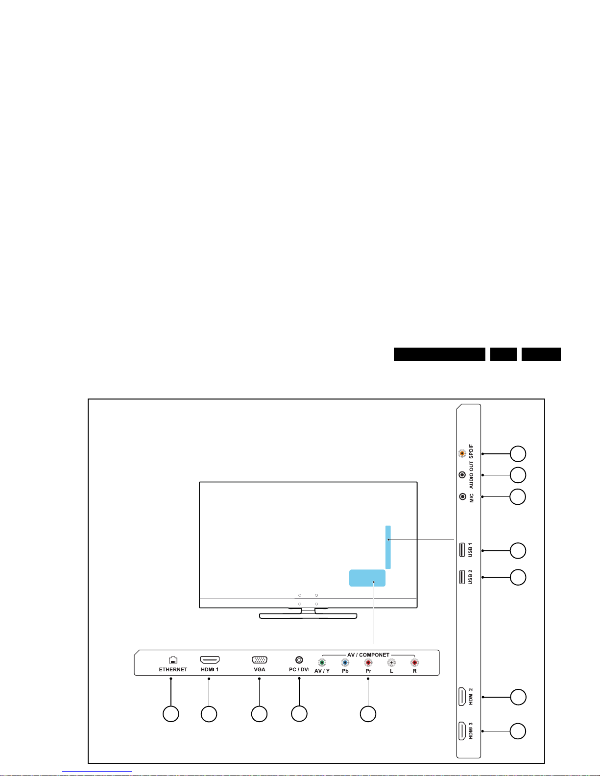
2.3 Connections
19740_001.eps
1
2
3
4
5
6
7
8
9
10
11
12

Technical Specs, Diversity, and Connections
EN 4 TPS14.4A LA2.
7 -D0+ Data channel j
8-Shield Gnd H
9 -D0- Data channel j
10 - CLK+ Data channel j
11 - Shield Gnd H
12 - CLK- Data channel j
13 - Easylink/CEC Control channel jk
14 - ARC Audio Return Channel k
15 - DDC_SCL DDC clock j
16 - DDC_SDA DDC data jk
17 - Ground Gnd H
18 - +5V j
19 - HPD Hot Plug Detect j
20 - Ground Gnd H
7 - HDMI 3: Digital Video - In, Digital Audio with ARC In/Out
Figure 2-5 HDMI (type A) connector
1 -D2+ Data channel j
2-Shield Gnd H
3 -D2- Data channel j
4 -D1+ Data channel j
5-Shield Gnd H
6 -D1- Data channel j
7 -D0+ Data channel j
8-Shield Gnd H
9 -D0- Data channel j
10 - CLK+ Data channel j
11 - Shield Gnd H
12 - CLK- Data channel j
13 - Easylink/CEC Control channel jk
14 - ARC Audio Return Channel k
15 - DDC_SCL DDC clock j
16 - DDC_SDA DDC data jk
17 - Ground Gnd H
18 - +5V j
19 - HPD Hot Plug Detect j
1 -Video Red 0.7 V
PP
/ 75 W j
2 -Video Green 0.7 V
PP
/ 75 W j
3 -Video Blue 0.7 V
PP
/ 75 W j
4-n.c.
5 -Ground Gnd H
6 - Ground Red Gnd H
7 - Ground Green Gnd H
8 - Ground Blue Gnd H
9-+5V
DC
+5 V j
10 - Ground Sync Gnd H
11 - Ground Red Gnd H
12 - DDC_SDA DDC data j
13 - H-sync 0 - 5 V j
14 - V-sync 0 - 5 V j
15 - DDC_SCL DDC clock j
11 - HDMI 1: Digital Video - In, Digital Audio with ARC In/Out
Figure 2-7 HDMI (type A) connector
1 -D2+ Data channel j
2 -Shield Gnd H
3 -D2- Data channel j
4 -D1+ Data channel j
5 -Shield Gnd H
6 -D1- Data channel j
7 -D0+ Data channel j
8 -Shield Gnd H
9 -D0- Data channel j
10 - CLK+ Data channel j
11 - Shield Gnd H
12 - CLK- Data channel j
13 - Easylink/CEC Control channel jk
14 - ARC Audio Return Channel k
15 - DDC_SCL DDC clock j
16 - DDC_SDA DDC data jk
17 - Ground Gnd H
18 - +5V j
10000_017_090121.eps
090428
19
1
18 2
10000_017_090121.eps
090428
19
1
18 2

Precautions, Notes, and Abbreviation List
EN 5TPS14.4A LA 3.
3. Precautions, Notes, and Abbreviation List
Index of this chapter:
3.1 Safety Instructions
3.2 Warnings
3.3 Notes
3.4 Abbreviation List
3.1 Safety Instructions
Safety regulations require the following during a repair:
• Connect the set to the Mains/AC Power via an isolation
transformer (> 800 VA).
• Replace safety components, indicated by the symbol h,
only by components identical to the original ones. Any
other component substitution (other than original type) may
increase risk of fire or electrical shock hazard.
Safety regulations require that after a repair, the set must be
returned in its original condition. Pay in particular attention to
the following points:
• Route the wire trees correctly and fix them with the
mounted cable clamps.
• Check the insulation of the Mains/AC Power lead for
external damage.
• Check the strain relief of the Mains/AC Power cord for
proper function.
• Check the electrical DC resistance between the Mains/AC
Power plug and the secondary side (only for sets that have
a Mains/AC Power isolated power supply):
1. Unplug the Mains/AC Power cord and connect a wire
between the two pins of the Mains/AC Power plug.
2. Set the Mains/AC Power switch to the “on” position
(keep the Mains/AC Power cord unplugged!).
3. Measure the resistance value between the pins of the
Mains/AC Power plug and the metal shielding of the
tuner or the aerial connection on the set. The reading
should be between 4.5 M and 12 M.
4. Switch “off” the set, and remove the wire between the
two pins of the Mains/AC Power plug.
• Check the cabinet for defects, to prevent touching of any
inner parts by the customer.
3.2 Warnings
3.3.2 Schematic Notes
• All resistor values are in ohms, and the value multiplier is
often used to indicate the decimal point location (e.g. 2K2
indicates 2.2 k).
• Resistor values with no multiplier may be indicated with
either an “E” or an “R” (e.g. 220E or 220R indicates 220 ).
• All capacitor values are given in micro-farads (10
-6
),
nano-farads (n 10
-9
), or pico-farads (p 10
-12
).
• Capacitor values may also use the value multiplier as the
decimal point indication (e.g. 2p2 indicates 2.2 pF).
• An “asterisk” (*) indicates component usage varies. Refer
to the diversity tables for the correct values.
• The correct component values are listed on the Philips
Spare Parts Web Portal.
3.3.3 Spare Parts
For the latest spare part overview, consult your Philips Spare
Part web portal.
3.3.4 BGA (Ball Grid Array) ICs
Introduction
For more information on how to handle BGA devices, visit this
URL: http://www.atyourservice-magazine.com
. Select
“Magazine”, then go to “Repair downloads”. Here you will find
Information on how to deal with BGA-ICs.
BGA Temperature Profiles
For BGA-ICs, you must use the correct temperature-profile.
Where applicable and available, this profile is added to the IC
Data Sheet information section in this manual.
3.3.5 Lead-free Soldering
Due to lead-free technology some rules have to be respected
by the workshop during a repair:
• Use only lead-free soldering tin. If lead-free solder paste is
required, please contact the manufacturer of your soldering

Precautions, Notes, and Abbreviation List
EN 6 TPS14.4A LA3.
result in sets which have the same CTN (Commercial Type
Number; e.g. 28PW9515/12) but which have a different B.O.M.
number.
By looking at the third digit of the serial number, one can
identify which B.O.M. is used for the TV set he is working with.
If the third digit of the serial number contains the number “1”
(example: AG1B033500001), then the TV set has been
manufactured according to B.O.M. number 1. If the third digit is
a “2” (example: AG2B0335000001), then the set has been
produced according to B.O.M. no. 2. This is important for
ordering the correct spare parts!
For the third digit, the numbers 1...9 and the characters A...Z
can be used, so in total: 9 plus 26= 35 different B.O.M.s can be
indicated by the third digit of the serial number.
Identification: The bottom line of a type plate gives a 14-digit
serial number. Digits 1 and 2 refer to the production centre (e.g.
SN is Lysomice, RJ is Kobierzyce), digit 3 refers to the B.O.M.
code, digit 4 refers to the Service version change code, digits 5
and 6 refer to the production year, and digits 7 and 8 refer to
production week (in example below it is 2010 week 10 / 2010
week 17). The 6 last digits contain the serial number.
6 = play 16 : 9 format, 12 = play 4 : 3
format
AARA Automatic Aspect Ratio Adaptation:
algorithm that adapts aspect ratio to
remove horizontal black bars; keeps
the original aspect ratio
ACI Automatic Channel Installation:
algorithm that installs TV channels
directly from a cable network by
means of a predefined TXT page
ADC Analogue to Digital Converter
AFC Automatic Frequency Control: control
signal used to tune to the correct
frequency
AGC Automatic Gain Control: algorithm that
controls the video input of the feature
box
AM Amplitude Modulation
AP Asia Pacific
AR Aspect Ratio: 4 by 3 or 16 by 9
ASF Auto Screen Fit: algorithm that adapts
aspect ratio to remove horizontal black
bars without discarding video
information
ATSC Advanced Television Systems
Committee, the digital TV standard in
the USA
ATV See Auto TV
Auto TV A hardware and software control
system that measures picture content,
and adapts image parameters in a
dynamic way
AV External Audio Video
AVC Audio Video Controller
AVIP Audio Video Input Processor
B/G Monochrome TV system. Sound
carrier distance is 5.5 MHz
BDS Business Display Solutions (iTV)
BLR Board-Level Repair
BTSC Broadcast Television Standard
Committee. Multiplex FM stereo sound
system, originating from the USA and
used e.g. in LATAM and AP-NTSC
countries

Precautions, Notes, and Abbreviation List
EN 7TPS14.4A LA 3.
DRAM Dynamic RAM
DRM Digital Rights Management
DSP Digital Signal Processing
DST Dealer Service Tool: special remote
control designed for service
technicians
DTCP Digital Transmission Content
Protection; A protocol for protecting
digital audio/video content that is
traversing a high speed serial bus,
such as IEEE-1394
DVB-C Digital Video Broadcast - Cable
DVB-T Digital Video Broadcast - Terrestrial
DVD Digital Versatile Disc
DVI(-d) Digital Visual Interface (d= digital only)
E-DDC Enhanced Display Data Channel
(VESA standard for communication
channel and display). Using E-DDC,
the video source can read the EDID
information form the display.
EDID Extended Display Identification Data
(VESA standard)
EEPROM Electrically Erasable and
Programmable Read Only Memory
EMI Electro Magnetic Interference
EPG Electronic Program Guide
EPLD Erasable Programmable Logic Device
EU Europe
EXT EXTernal (source), entering the set by
SCART or by cinches (jacks)
FDS Full Dual Screen (same as FDW)
FDW Full Dual Window (same as FDS)
FLASH FLASH memory
FM Field Memory or Frequency
Modulation
FPGA Field-Programmable Gate Array
FTV Flat TeleVision
Gb/s Giga bits per second
G-TXT Green TeleteXT
H H_sync to the module
HD High Definition
HDD Hard Disk Drive
HDCP High-bandwidth Digital Content
Protection: A “key” encoded into the
a maximum data rate of 270 Mbit/s,
with a minimum bandwidth of 135
MHz.
iTV Institutional TeleVision; TV sets for
hotels, hospitals etc.
LS Last Status; The settings last chosen
by the customer and read and stored
in RAM or in the NVM. They are called
at start-up of the set to configure it
according to the customer's
preferences
LATAM Latin America
LCD Liquid Crystal Display
LED Light Emitting Diode
L/L' Monochrome TV system. Sound
carrier distance is 6.5 MHz. L' is Band
I, L is all bands except for Band I
LPL LG.Philips LCD (supplier)
LS Loudspeaker
LVDS Low Voltage Differential Signalling
Mbps Mega bits per second
M/N Monochrome TV system. Sound
carrier distance is 4.5 MHz
MHEG Part of a set of international standards
related to the presentation of
multimedia information, standardised
by the Multimedia and Hypermedia
Experts Group. It is commonly used as
a language to describe interactive
television services
MIPS Microprocessor without Interlocked
Pipeline-Stages; A RISC-based
microprocessor
MOP Matrix Output Processor
MOSFET Metal Oxide Silicon Field Effect
Transistor, switching device
MPEG Motion Pictures Experts Group
MPIF Multi Platform InterFace
MUTE MUTE Line
MTV Mainstream TV: TV-mode with
Consumer TV features enabled (iTV)
NC Not Connected
NICAM Near Instantaneous Compounded
Audio Multiplexing. This is a digital

Precautions, Notes, and Abbreviation List
EN 8 TPS14.4A LA3.
PFC Power Factor Corrector (or
Pre-conditioner)
PIP Picture In Picture
PLL Phase Locked Loop. Used for e.g.
FST tuning systems. The customer
can give directly the desired frequency
POD Point Of Deployment: a removable
CAM module, implementing the CA
system for a host (e.g. a TV-set)
POR Power On Reset, signal to reset the uP
PSDL Power Supply for Direct view LED
backlight with 2D-dimming
PSL Power Supply with integrated LED
drivers
PSLS Power Supply with integrated LED
drivers with added Scanning
functionality
PTC Positive Temperature Coefficient,
non-linear resistor
PWB Printed Wiring Board (same as “PCB”)
PWM Pulse Width Modulation
QRC Quasi Resonant Converter
QTNR Quality Temporal Noise Reduction
QVCP Quality Video Composition Processor
RAM Random Access Memory
RGB Red, Green, and Blue. The primary
color signals for TV. By mixing levels
of R, G, and B, all colors (Y/C) are
reproduced.
RC Remote Control
RC5 / RC6 Signal protocol from the remote
control receiver
RESET RESET signal
ROM Read Only Memory
RSDS Reduced Swing Differential Signalling
data interface
R-TXT Red TeleteXT
SAM Service Alignment Mode
S/C Short Circuit
SCART Syndicat des Constructeurs
d'Appareils Radiorécepteurs et
Téléviseurs
SCL Serial Clock I
2
C
SCL-F CLock Signal on Fast I
2
C bus
SXGA 1280 × 1024
TFT Thin Film Transistor
THD Total Harmonic Distortion
TMDS Transmission Minimized Differential
Signalling
TS Transport Stream
TXT TeleteXT
TXT-DW Dual Window with TeleteXT
UI User Interface
uP Microprocessor
UXGA 1600 × 1200 (4:3)
V V-sync to the module
VESA Video Electronics Standards
Association
VGA 640 × 480 (4:3)
VL Variable Level out: processed audio
output toward external amplifier
VSB Vestigial Side Band; modulation
method
WYSIWYR What You See Is What You Record:
record selection that follows main
picture and sound
WXGA 1280 × 768 (15:9)
XTAL Quartz crystal
XGA 1024 × 768 (4:3)
Y Luminance signal
Y/C Luminance (Y) and Chrominance (C)
signal
YPbPr Component video. Luminance and
scaled color difference signals (B-Y
and R-Y)
YUV Component video

Mechanical Instructions
EN 9TPS14.4A LA 4.
4. Mechanical Instructions
Index of this chapter:
4.1 Cable Dressing
4.2 Service Positions
4.3 Assembly/Panel Removal (for 55PFH6009/96)
4.4 Assembly/Panel Removal (for 42"/50"PFH5009 series)
4.5 Set Re-assembly
Notes:
• Figures below can deviate slightly from the actual situation,
due to the different set executions.
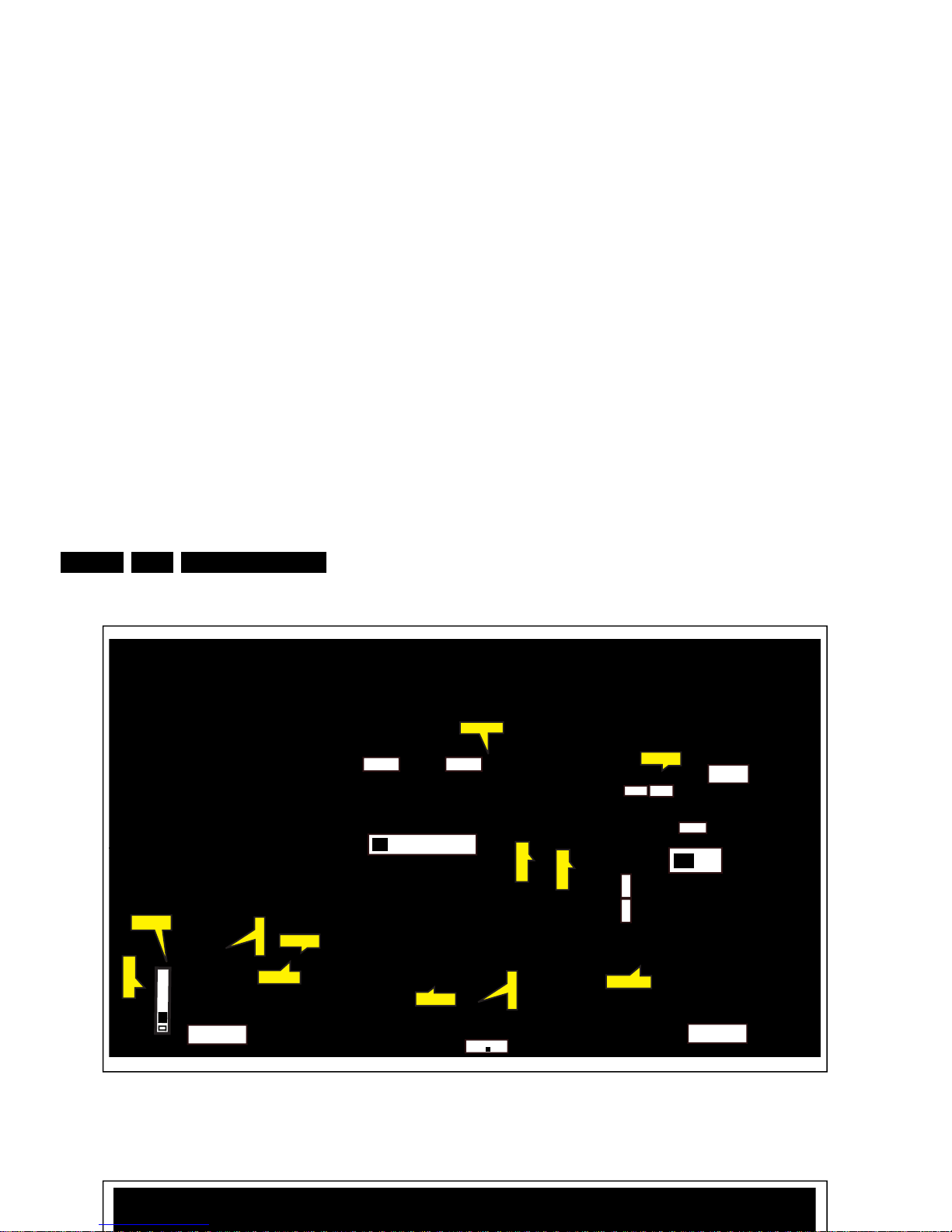
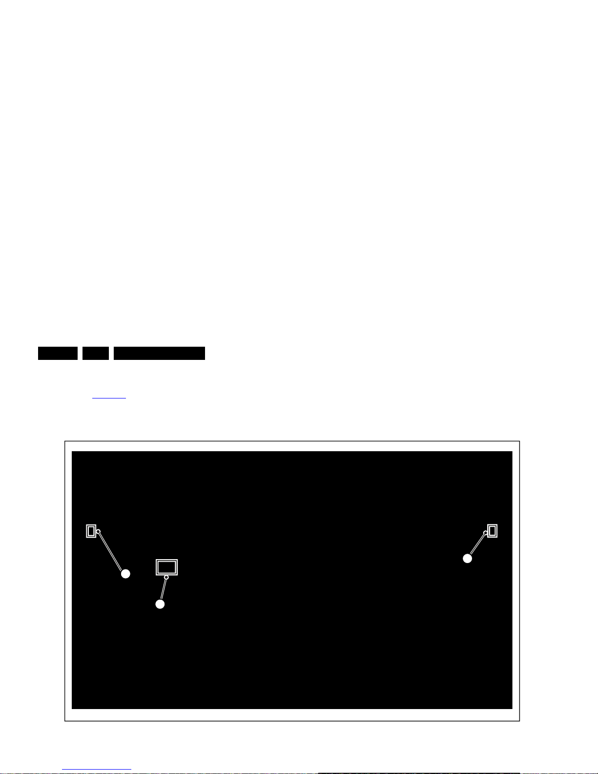
4.1 Cable Dressing
19741_100.eps
CN403
CN701
CN8101
CN9101
CN601
CN401
CN103
MAIN POWER SUPPLY
(1054)
A
SSB
(1053)
B
ECN701
ECN401
ECN401
ECN403
ECN103
ECN103
ECN601
ECN601
ECN601
LOUDSPEAKER
(1184)
LOUDSPEAKER
(1184)
IR/LED BOARD
(1056)
J
KEYBOARD CONTROL
(1057)
E
CN01
ECN401
WIFI Module
(WiFi01)
Mechanical Instructions
EN 10 TPS14.4A LA4.
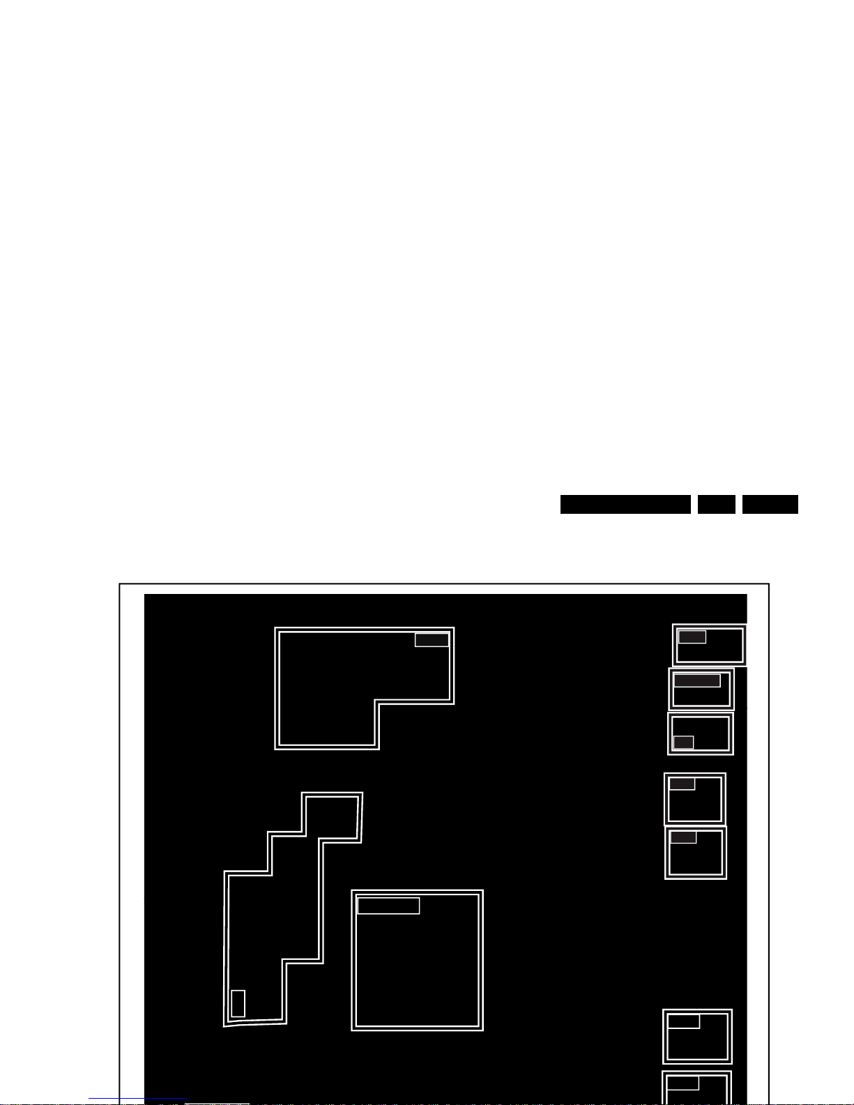
Figure 4-2 Cable dressing (5009 series 50")
19741_101.eps
CN403
CN701
CN8101
CN9301
CN601
CN401
CN103
MAIN POWER SUPPLY
(1054)
A
SSB
(1053)
B
ECN701
ECN601
ECN401
ECN401
ECN403
ECN403
ECN103
ECN103
ECN601
ECN601
ECN401
LOUDSPEAKER
(1184)
LOUDSPEAKER
(1184)
IR/LED BOARD
(1056)
J
KEYBOARD CONTROL
(1057)
E
CN01
ECN401
WIFI Module
(WiFi01)
Mechanical Instructions
EN 11TPS14.4A LA 4.
4.2 Service Positions
For easy servicing of a TV set, the set should be put face down
on a soft flat surface, foam buffers or other specific workshop
tools. Ensure that a stable situation is created to perform
measurements and alignments. When using foam bars take
care that these always support the cabinet and never only the
display. Caution: Failure to follow these guidelines can
seriously damage the display!
Ensure that ESD safe measures are taken.
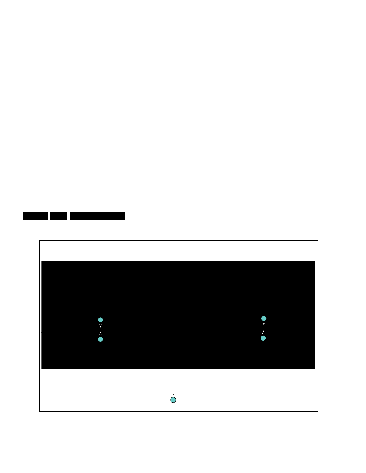
4.3 Assembly/Panel Removal (for 55PFH6009/96)
Instructions below apply to the 55PFH6009/96.
4.3.1 Rear Cover
Refer to Figure 4-4
for details.
Warning: Disconnect the mains power cord before removing
the rear cover.
1. Remove fixation screws [1] that secure the base assy, pull
out the base assy from the set. Then remove the fixation
screws [2], [3] and [4] that secure the rear cover. Refer to
Figure 4-4
for details.
2. Gently lift the rear cover from the TV. Make sure that wires
and cables are not damaged while lifting the rear cover
from the set.
2
2
2
2
2
2
2
2
2
4
2
2
2
4
4
4
4
2
2
1
1
1
1
3
1
M4 × 10
M3× 6
2
Q3 × 8
3
Q4 × 10
Mechanical Instructions
EN 12 TPS14.4A LA4.
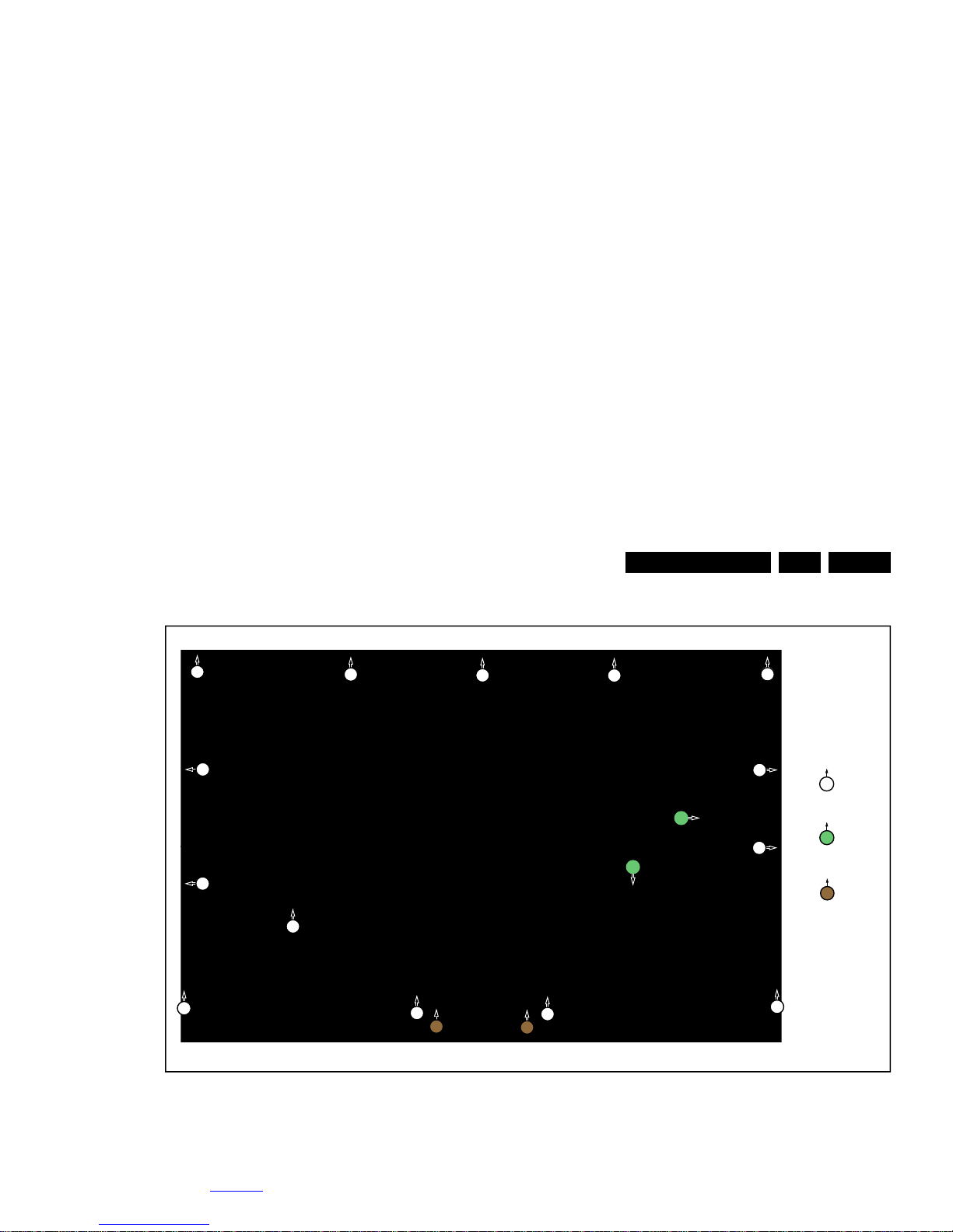
4.3.2 AmbiLight Panel
Refer to Figure 4-5
for details.
1. Gently release the clamps and unplug the two connectors
[1,2] that secure the ambilight panels. Release the clips
from the FFC connector that connect with the AmbiLight
control panel [3].
2. Lift the AmbiLight panel from the rear cover. Make sure that
wires and flat foils are not damaged while lifting the
ambilight panel from the rear cover.
Figure 4-5 Ambilight Panel removal
4.3.3 Small Signal Board (SSB)
19740_102.eps
1
2
3

Mechanical Instructions
EN 13TPS14.4A LA 4.
4.3.4 Power Supply Unit (PSU)
Caution: it is mandatory to remount all different screws at their
original position during re-assembly. Failure to do so may result
in damaging the PSU.
1. Gently unplug all connectors from the PSU.
2. Remove all fixation screws from the PSU.
3. The PSU can be taken out of the set now.
4.3.5 Speakers
1. Gently release the tapes that secures the speaker cables.
2. Unplug the speaker connectors from the SSB.
3. Take the speakers out.
When defective, replace the both units.
4.3.6 Keyboard Control unit
1. Unplug the connector from the keyboard control panel.
2. Gently push inwards the two clips at the PSU side of the
unit. Release the unit at the PSU side and turn it away from
the PSU. Now push it towards the PSU to release the
catches at the other side of the unit. Take it out from the
metal bracket.
When defective, replace the whole unit.
4.3.7 Stand bracket
1. Remove all fixation screws of the bracket.
2. Lift the bracket from the set.
4.3.8 IR/LED Panel
1. Remove the stand bracket, as described earlier.
2. Remove fixation screw that secure the deco rear cover and
take it out from the deco.
3. Unplug the connector from the IR/LED panel.
4. Gently release the double faced adhesive tape that pasted
the panel and take it out from the deco.
When defective, replace the whole unit.
4.3.9 WIFI module
4.4.1 Stand
Refer to Figure 4-7
for details.
1. Remove the fixation screws [1] that secure the stand
bracket. Refer to Figure 4-7
for details.
2. Take the stand bracket out from the set.
Mechanical Instructions
EN 14 TPS14.4A LA4.
Figure 4-7 Stand removal
4.4.2 Rear Cover
Refer to Figure 4-8
for details.
Warning: Disconnect the mains power cord before removing
the rear cover.
19741_103.eps
M4× 16
1
1
1
1
1
Mechanical Instructions
EN 15TPS14.4A LA 4.
Figure 4-8 Rear cover removal
4.4.3 Keyboard Control Unit
Refer to Figure 4-9
for details.
1. Release the connector [2] from the keyboard control panel.
Caution: be careful, as these are very fragile connectors!
19741_102.eps
2
2
2
2
2
2
2
2
4
2
2
2
4
4
2
2
2
3
3
M3× 8
2
M3 × 6
3
Q3 × 8

Mechanical Instructions
EN 16 TPS14.4A LA4.
Figure 4-9 Keyboard Control unit removal
4.4.4 Small Signal Board (SSB)
Refer to Figure 4-10
for details.
Caution: it is mandatory to remount all different screws at their
original position during re-assembly. Failure to do so may result
19741_104.eps
1
1
2
3
3

Mechanical Instructions
EN 17TPS14.4A LA 4.
4.4.6 Speakers
1. Gently release the tapes that secure the speaker cables.
2. Unplug the speaker connector from the SSB.
3. Take the speakers out.
When defective, replace the both units.
4.4.7 IR/LED Board
1. Remove the stand bracket as described earlier.
2. Gently release the clips that hold the board and take it out
from the bezel.
3. Unplug both the connectors from the IR/LED board.
When defective, replace the whole unit.
4.4.8 LCD Panel
1. Remove the SSB as described earlier.
2. Remove the PSU as described earlier.
3. Remove the keyboard control panel as described earlier.
4. Remove the stand bracket as described earlier.
5. Remove the IR/LED as described earlier.
6. Remove the fixations screws that fix the metal clamps to
the front bezel. Take out those clamps.
7. Remove all other metal parts not belonging to the panel.
8. Lift the LCD Panel from the bezel.
When defective, replace the whole unit.
4.5 Set Re-assembly
To re-assemble the whole set, execute all processes in reverse
order.
Notes:
• While re-assembling, make sure that all cables are placed
and connected in their original position. See Figure 4-1
to
Figure 4-3
.
• Pay special attention not to damage the EMC foams on the
SSB shields. Ensure that EMC foams are mounted
correctly.

Service Modes and Fault Finding
EN 18 TPS14.4A LA5.
5. Service Modes and Fault Finding
Index of this chapter:
5.1 Test Points
5.2 Service Modes
5.3 Stepwise Start-up
5.4 Software Upgrading
5.5 Fault Finding and Repair Tips
5.1 Test Points
As most signals are digital, it will be difficult to measure
waveforms with a standard oscilloscope.
Perform measurements under the following conditions:
• Service Default Mode.
• Video: Colour bar signal.
• Audio: 3 kHz left, 1 kHz right.
5.2 Servi ce Modes
The Service Mode feature is split into five parts:
• Factory Mode.
The Factory mode offer features, which can be used by the
Service engineer to repair/align a TV set. Some features are:
• Make alignments (e.g. White Tone), reset the error buffer
(Factory Mode).
Note: For the new model range, a new remote control (RC) is
used with some renamed buttons. This has an impact on the
activation of the Service modes. For instance the old “MENU”
button is now called “HOME” (or is indicated by a “house” icon).
5.2.1 Contents of the Factory mode:
Purpose
• To perform extended alignments.
Specifications
• Displaying and or changing Panel ID information.
• Various software alignment settings.
• Testpattern displaying.
• Public Broadcasting Service password Reset.
•etc.
How to Activate the Factory mode
To activate the Factory mode, use the following method:
• Press the following key sequence on the remote control
transmitter: from the “Home screen” press “1999”, directly
followed by the “Back” button. Do not allow the display to
time out between entries while keying the sequence.
After entering the Factory mode, the following items are
displayed,
Table 5-1 Factory mode overview
Item Item value
Default value
Description42" 50" 55"
0 Brand Philips-TWN Philips-TWN Brand name
1 Model 42PFH5009/96 50PFH5009/96 55PFH6009/96 Model name
2HW Ver Hardware Version
3 SW Ver 2.00_20140703_16
14_42
2.00_20140703_17
16_50
2.14_20140416_1931Software Version
4 Date The Jul 3 16:27:03
CST 2014
The Jul 3 17:22:04
CST 2014
Wed Apr 16
19:41:58 CST 2014
Software release date
5 Scaler Scaler model
6 Tuner Tuner
7 Panel LCA420HVN06AD
LCM500J1PE8AC2
LCA550HVN01AD6
Display Panel model
Service Modes and Fault Finding
EN 19TPS14.4A LA 5.
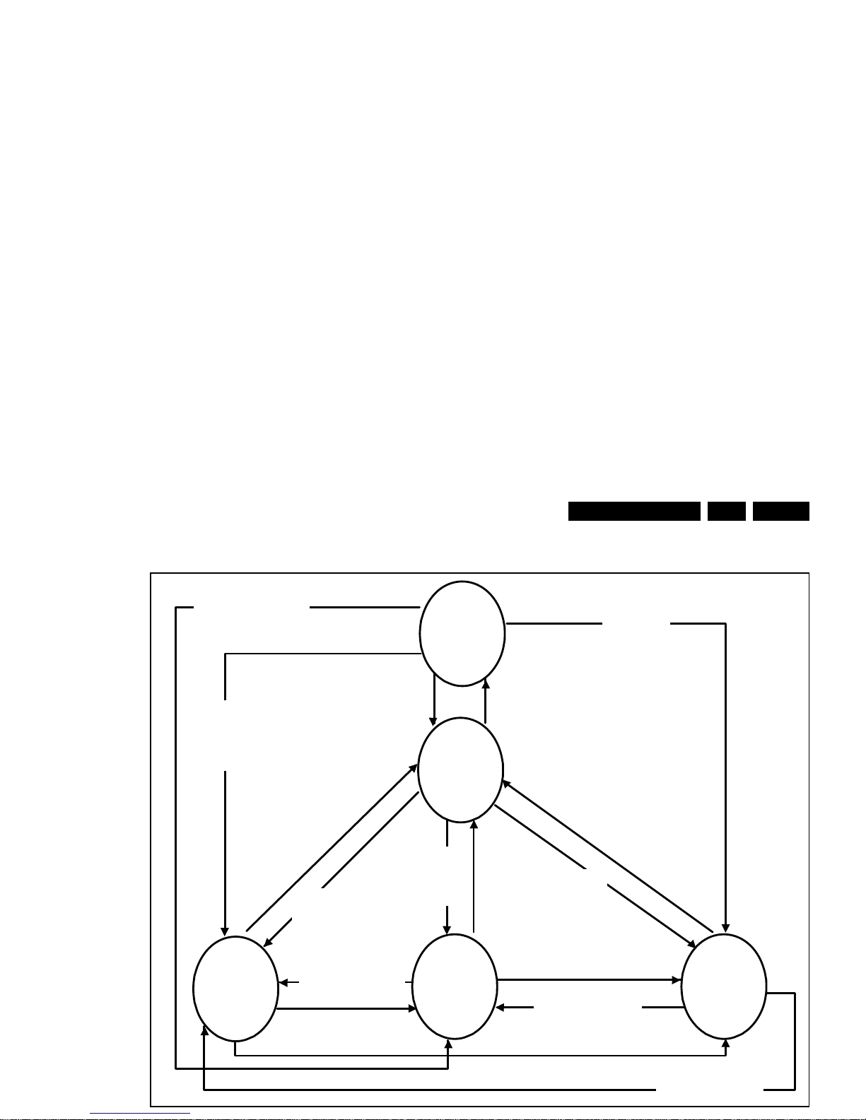
5.3 Stepwise Start-up
19080_206_110323.eps
Power Off
Standby
Soft Mode
Power On
Semi-
Standby
Standby
Switch
Off(Mains
Power Plug)
Standby Soft Mode
Command Received,
previously in Standby
Soft Mode (Power tact
switch)
TV Wakeup
commands
Received
(TV Wakeup
keys)
Digital
background
tasks started
Digital
background
tasks completed
Swith On,
previously in
Standby/Semi-
Standby (Mains
Power Plug)
Standby
Soft Mode
Command
Received
(Power tact
switch)
Switch Off (Mains
Power Plug)
Switch Off
(Mains Power
Plug)
Swith On,
previously in
Standby Soft Mode
(Mains Power Plug)
Standby
commands
Received (RC
Standby key)
Standby Soft Mode
Command Received,
previously in Standby
Soft Mode (Power
tact switch)
TV Wakeup
commands
Received
(TV Wakeup
keys)
Switch On, previously
in Power On Mode
(Power tact switch)
Standby Soft Mode
Command Received,
(Power tact switch)
Switch Off (Mains
Power Plug)
Switch On,previously in
TV Operation Mode
(Mains Power Plug)

Service Modes and Fault Finding
EN 20 TPS14.4A LA5.
5.4.5 Update the TV software
1. Turn the TV on and wait for it to boot completely.
2. Insert the USB memory stick that contains the software
update files in one of the TV’s USB ports.
3. The TV will detect the USB memory stick automatically.
Then a window jumps out as Figure 5-2
.
Note: If the USB flash drive is not detected after power up,
disconnect it and re-insert it. And no change the software
name.
4. Select [Confirm] and press OK to start software updates.
See Figure 5-2
.
5. Upgrading will now begins and the status of the updating
progress will be displayed. See Figure 5-3
.
6. When the TV software is updated. Remove your USB flash
drive, and the TV will turn on automatically.
Figure 5-2 Update the TV software [1/2]
• FUS_clustername_version.zip: Contains the
“autorun.bin” which is needed to upgrade the TV main
software and the software download application.
• NVM_clustername_version.zip: Default NVM content.
Must be programmed via ComPair.
5.4.7 How to Copy NVM Data to/from USB
When copying data to and from a USB memory stick, the folder
“repair” is used. When inserting an empty USB memory stick,
and downloading data to the stick, the TV will create this folder.
When sending data from a USB memory stick to a TV, the
intended data must be available in the “repair” folder.
Note that when copying EDID data to the TV, all necessary
EDID files must be in this folder.
Service mode overview for your reference.
5.5 Fault Finding and Repair Tips
Note:
• It is assumed that the components are mounted correctly
with correct values and no bad solder joints.
• Before any fault finding actions, check if the correct options
are set.
5.5.1 No Picture via HDMI input
Check if HDCP key is valid. This can be done in CSM.
5.5.2 TV Will Not Start-up from Stand-by
Possible Stand-by Controller failure. Re-flash the software.
5.5.3 Audio Amplifier
The Class D-IC U602 has a powerpad for cooling. When the IC
is replaced it must be ensured that the powerpad is very well
pushed to the PWB while the solder is still liquid. This is needed
to insure that the cooling is guaranteed, otherwise the Class
D-IC could break down in short time.
5.5.4 Loudspeakers
19452_200_130902.eps
130902
Confirm
No

Alignments
EN 21TPS14.4A LA 6.
6. Alignments
Index of this chapter:
6.1 General Alignment Conditions
6.2 Reset of Repaired SSB
6.1 General Alignment Conditions
Perform all electrical adjustments under the following
conditions:
• Power supply voltage: 90 - 264 V
AC
, 50/ 60 3 Hz.
• Connect the set to the mains via an isolation transformer
with low internal resistance.
• Allow the set to warm up for approximately 15 minutes.
• Measure voltages and waveforms in relation to correct
ground (e.g. measure audio signals in relation to
AUDIO_GND).
Caution: It is not allowed to use heat sinks as ground.
• Test probe: R
i
> 10 M, Ci < 20 pF.
• Use an isolated trimmer/screwdriver to perform
alignments.
6.2 Reset of Repaired SSB
A very important issue towards a repaired SSB from a Service
repair shop (SSB repair on component level) implies the reset
of the NVM on the SSB.
After a repaired SSB has been mounted in the set (set repair
on board level), the type number (CTN) and production code of
the TV has to be set according to the type plate of the set.
6.2.1 SSB Identification
SSB’s of this chassis are identified by a “715” code on the SSB.
715Axxxx-Nnn-MMM-OOOO
• 715 main category, Printed Wiring Board
• Axxxx sub category, sequential coding number
• Nnn Version code
• N Development number
• nn Production number
• MMM Mounting variation code
• OOOO Optional variation code
Make sure when replacing an SSB the SSB identification codes
match the replacement board.

Circuit Descriptions
EN 22 TPS14.4A LA7.
7. Circuit Descriptions
Index of this chapter:
7.1 Introduction
7.2 Power Supply
7.3 DC/DC Converters
7.4 Front-End Analogue ATV reception
7.5 HDMI
7.6 Video and Audio Processing - MSD8560QV
Notes:
•Only new circuits (circuits that are not published recently)
are described.
• Figures can deviate slightly from the actual situation, due
to different set executions.
• For a good understanding of the following circuit
descriptions, please use the wiring, block (see chapter
9. Block Diagrams
) and circuit diagrams (see chapter
10. Circuit Diagrams and PWB Layouts
).Where necessary,
you will find a separate drawing for clarification.
7.1 Introduction
The TPS14.4A LA is a new chassis launched in Taiwan in
2014. The whole range is covered by MSD8560QV. The major
deltas versus its predecessor support DVB-T/NTSC, with
multi-media, Ethernet, Ambilight, WIFI, ARC, MIC, SPDIF
Output functionality.
The TPS14.4A LA chassis comes with the following stylings:
• series xxPFH6009xx
• series xxPFH5009xx
7.1.1 Implementation
Key components of this chassis are:
• SCALER MSD8560QV-XZ PBGA-707
• TUNER - TDSH-T070F
• AUDIO WM8782SEDS/RV SSOP-20
• AUDIO AD82588B-LG48NAY 2x15W stereo E-LQ
• AUDIO WM8524CGEDT/R / TSSOP-16 4.5V
• FLASH THGBMAG6A2JBAIR 8GB BGA-153
7.1.2 TPS14.4A LA Architecture Overview
For details about the chassis block diagrams refer to chapter 9.
Block Diagrams. An overview architecture can be found in
Figure 9.1
.
Circuit Descriptions
EN 23TPS14.4A LA 7.
7.1.3 SSB Cell Layout
MSD8560QV
DDR
HDMI
HDMI
DC/DC
USB
USB
Audio Out
MIC
SPDIF
Circuit Descriptions
EN 24 TPS14.4A LA7.
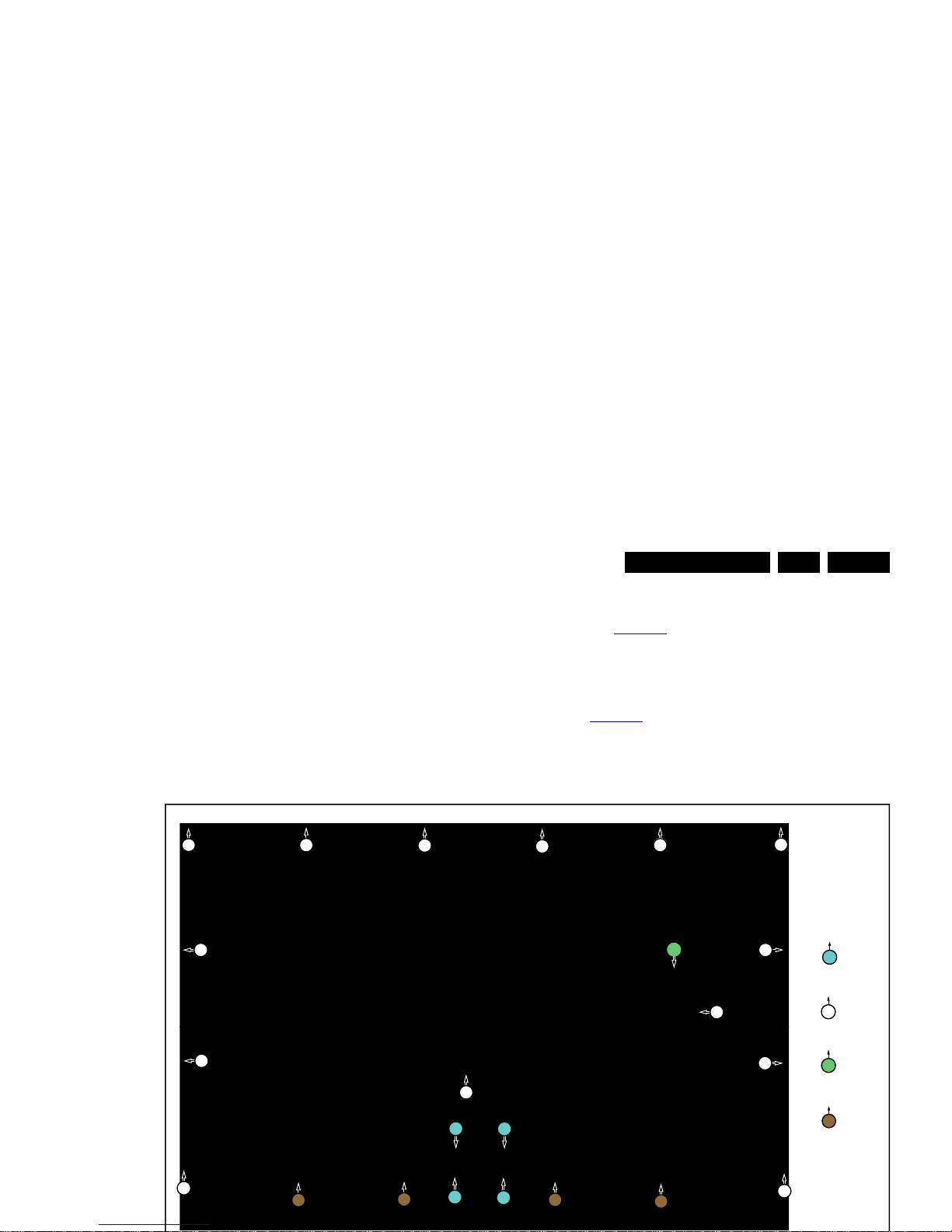
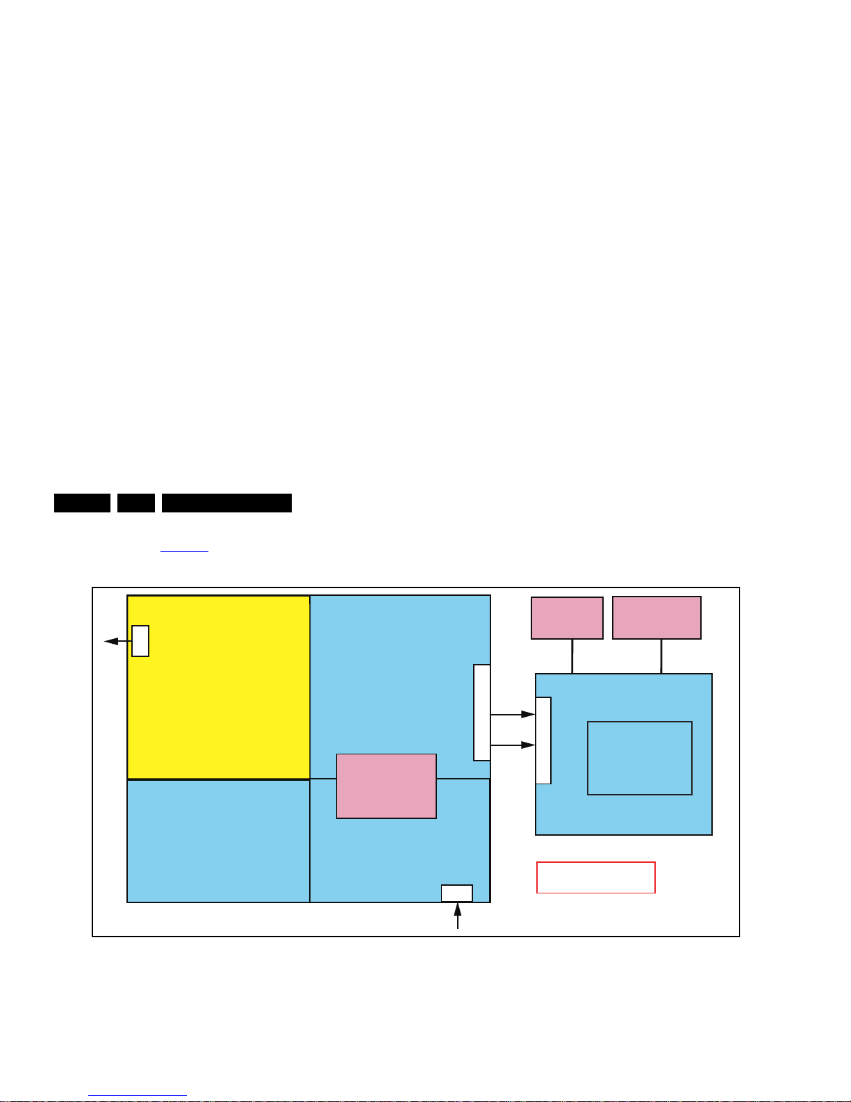
7.2 Power Supply
Refer to figure Figure 7-2 for the power architecture of this
platform.
Figure 7-2 Power Architecture
7.2.1 Power Supply Unit
All power supplies are a block box for Service. When defective,
a new board must be ordered and defective one must be
returned, unless the main fuse of the board is broken. Always
replace a defective fuse with one with the correct
specifications. This part is available in the regular market.
Consult the Philips Service web portal for the order codes of the
• Output to the display; in case of
- IPB: High voltage to the LCD panel
- PSL and PSLS (LED-driver outputs)
- PSDL (high frequent) AC-current.
7.2.2 Diversity
Display power
Platform
MSD8560QV
PFC
Platform power
1 power- PCB
AMP
LVDS
AMP
Low stby
power
Ac-input + Mains filter
BL-ON/OFF
AC IN
DIM
12V/24V
12V12V
+12V-Audio
Display Interfacing
CN8501
CN8101
CN9901
CN701
19740_201.eps
 Loading...