

Page 1

.
.
.
.
.
Published by JH 667 TV Service Printed in the Netherlands Subject to modification EN 3122 785 16590
©
Copyright 2006 Philips Consumer Electronics B.V. Eindhoven, The Netherlands.
All rights reserved. No part of this publication may be reproduced, stored in a
ret
rieval system or transmitted, in any form or by any means, electronic,
mecha
nical, photocopying, or otherwise without the prior permission of Philips.
Colour Television Chassis
TPE1.0U PA
DDeessccrriipp ttiioonn PPaaggee
Revision List.....................................………. 2
Important Safety Notice................................ 3
Warning/Caution/Notice of PANEL .............. 4
Technical Specification................................. 8
Connecting the PDP...................................... 14
Input interfaces.............................................. 18
Top Key and Remote control ........................
OSD Tree .......................................... .......... .. 21
OSD operation ...................... ...................... . 24
Trouble shooting .... ................. ................... 44
Repair flow chart ............ .................. .......... . 46
White-Balance adjustment ............. ............. . 51
Software upgrade ........................................ 53
Function block diagram ............................... 55
Waveform of signals .................................... 60
Wiring diagram............................................. 62
Mechanical Instructions................................ 63
Disassembly and assembly ......................... 68
Definition of pixel defects ............................ 72
Block diagram ............................ ................. 75
UART diagram........................... ................. 81
Analog I/O diagram ................... ................. 82
Audio diagram ........................... ................. 83
Supply+RS232 diagram............. ................. 85
DC/DC diagram........................... ................. 86
Video-DAC diagram...................................... . 87
19
DDeesscc rriipp ttiioonn PPaaggee
Display interface diagram.............................
PNX2015 supply diagram............................. . 89
PNX2015 standby&control diagram.............. 90
PNX2015 DDR interface diagram................. . 91
PNX2015 Tunnelbus diagram....................... . 92
PNX2015 DV I/O diagram............................. . 93
PNX2015 Audio/Video diagram..................... 94
Miscellaneous diagram.................................
EEPROM diagram..... ............ ............ ............ . 96
VIPER supply diagram.................................. . 97
A/V+Tunnelbus diagram................................ 98
Main Memory diagram.................................. . 99
Control diagram............................................. 100
HDMI I/O+control diagram............................ 101
HDMI + supply diagram................................ 102
Main Tuner diagram...................................... 103
Channel decoder diagram............................
Audio amplifier diagram................................
Audio Source Selection diagram.................. 106
IF + SAW filter diagram................................ 107
MPIF main supply diagram........ .................. 108
Video source selection diagram .................. 109
PDC diagram............................. .................. 110
Audio output diagram................................... 111
Side AV diagram.......................................... 112
Key control diagram..................................... 113
88
95
104
105
DDeesscc rriipp ttiioonn PPaaggee
IR diagr am...... .. .. .... .. .... ... .... .. .. .... .. . .. ... .... .. .. . 114
OFPC diagra m.... .. .... .. .... .. .. .. .... .. .... .. ... .... .. ... 115
AC filter diag ram.. ..... .. .. .. .... .. .... .. .... .. ... .... .. ... . 116
US B filter diagram... .... .. ... ... .... .. .... .. ..... . ... .... .. 117
Image b oard PC B... .... ..... ... .. .... .... .. ..... . ... .... .. 118
Powe r bo ard PC B... .... .. ... ... .... .. .... .. ..... . ... .... .. 120
OFPC PC B .. ... .. .... .... .. ..... . ... .. .... .. .... .. ... .... .. ... 121
AC filter bo ard PC B... .. .. ..... .. .. .... .. .... ... .... .. .. ...122
US B board P C B.... .... .... ... .... .. .... .... .. ..... . ... .... 123
Side AV bo ard PC B... .. .... ... .. .... .. .... .. ... .... .. .. ...124
Audio output board /Key board PC B. .. .. ... .... .. 125
IR bo ard PC B... .... .. .... ... .. ... ... .. .. .. .... ... .... .. .. ... 126
Recommend ed par ts lis t..... .. ... .. .... ..... . ... .... ..127
Complete p arts list …… ………………………
Different par t lis t.... .... .. .... .... .. .. .... .. .... ... .... .. .. . TBD
Page 2

0-2-0 042MF231D/370
Back to cover
Revision List
Version Release Date Revision History
A00 Jun 12, 2006 Initial release, Draft Version
Page 3

0-3-0 042MF231D/370
Back to cover
Proper service and repair is important to the safe, reliable operation of all Equipment. The service procedures
recommended by PHILIPS and described in this service manual are effective methods of performing service
operations. Some of these service operations require the use of tools specially designed for the purpose. The
special tools should be used when and as recommended.
It is important to note that this manual contains various CAUTIONS and NOTICES which should be carefully
read in order to minimize the risk of personal injury to service personnel. The possibility exists that improper
service methods may damage the equipment. It is also important to understand that these CAUTIONS and
NOTICES ARE NOT EXHAUSTIVE. PHILIPS could not possibly know, evaluate and advise the service trade of
all conceivable ways in which service might be done or of the possible hazardous consequences of each way.
Consequently, PHILIPS has not undertaken any such broad evaluation. Accordingly, a servicer who uses a
service procedure or tool which is not recommended by PHILIPS must first satisfy himself thoroughly that
neither his safety nor the safe operation of the equipment will be jeopardized by the service method selected.
WARNING
Use of substitute replacement parts, which do not have the same specified safety characteristics may create
shock, fire, or other hazards.
Under no circumstances should the original design be modified or altered without written permission from
Philips.
Philips assumes no liability, express or implied, arising out of any unauthorized modification of design.
Servicer assumes all liability.
FOR PRODUCTS CONTAINING LASER:
DANGER- Invisible laser radiation when open. AVOID DIRECT EXPOSURE
TO BEAM.
CAUTION- Use of controls or adjustments or performance of procedures
other than those specified herein may result in hazardous
radiation exposure.
CAUTION- The use of optical instruments with this product will increase eye
hazard.
TO ENSURE THE CONTINUED RELIABILITY OF THIS PRODUCT, USE ONLY
ORIGINAL MANUFACTURER'S REPLACEMENT PARTS, WHICH ARE LISTED
WITH THEIR PART NUMBERS IN THE PARTS LIST SECTION OF THIS
SERVICE MANUAL.
Page 4

0-4-0 042MF231D/370
Back to cover
WARNING
- The Module is controlled by high voltage about 350V. If you need to handle the Module during operation or
just after power-off, you must take proper precautions against electric shock and must not touch the drive
circuit portion and metallic part of Module within 5 minutes. The capacitors in the drive circuit portion remain
temporarily charged even after the power is turned off. After turning off the power, you must be sure to wait
at least one minute before touching the Module. If the remain voltage is strong enough, it could result in
electric shock.
- Do not use any other power supply voltage other than the voltage specified in this product specifications. If
you use power voltage deviated from the specifications, it could result in product failure.
- Do not operate or install under the deviated surroundings from the environmental specification set for the
below; in moisture, rain or near water-for example, bath tub, laundry tub, kitchen sink; in a wet basement; or
near a swimming pool; and also near fire or heater - for example, near or over radiator or heat resistor; or
where it is exposed to direct sunlight; or somewhere like that. If you use the Module in places mentioned
above, it could result in electric shock, fire hazard or product failure.
- If any foreign objects (e.g. water, liquid and metallic chip or dust) entered the Module, the power supply
voltage to the Module must be turned off immediately. Also, never push objects of any kind into the Module
as they may touch dangerous voltage point or make short circuits that could result in fire hazard or electric
shock.
- If smoke, offensive smell or unusual noise should come from the Module, the power supply voltage to the
Module must be turned off immediately. Also, when the screen fails to display any picture after the power-on
or during operation, the power supply must be turned off immediately. Do not continue to operate the
Module under these conditions.
- Do not disconnect or connect the Module's connector while the power supply is on, or immediately after
power off. Because the Module is operated by high voltage, and the capacitors in drive circuit remain
temporarily charged even after the power is turned off. If you need to disconnect or reconnect it, you have to
wait at least one minute after power off.
- Do not disconnect or connect the power connector by a wet hand. The voltage of the product may be strong
enough to cause an electric shock.
- Do not damage the power cable of the Module, also do not modify it.
- When the power cable or connector is damaged or frayed, do not use it.
- When the power connector is covered with dust, please wipe it out with a dry cloth before power on.
Page 5

0-5-0 042MF231D/370
Back to cover
NOTICE
- To prevent defect or failure, please check the cable connections and power-supply condition before
power-on.
- The Module is controlled by high voltage. Not only during operation but also immediately after power-off, do
not disconnect or reconnect the Module's connector because it may result in failure. If you need to
disconnect or reconnect, you have to wait at least one minute after power-off.
- The Module is equipped with various protection circuits that automatically stop the Module operation, if an
interface signal or the power voltage becomes abnormal during operation. If the Module stops suddenly
during operation, please check the conditions of input signal or power source before restarting.
- For the protection of the circuit, if an abnormal situation is occurred, the high output voltage will be shut
down by (watching) the internal input voltage (Vs/ Va/ Vcc). In this case, the Module power resetting is
necessary to recover. There are also fuses in the Vs and Va power supply system to prevent smoking and
firing by the excessive current. The protecting function of the address driver of keeping a supervisory
device for the internal current is provided in the Va power supply system. Therefore, the number of
sub-frames decreases to a proper value when the Ia current exceeds a constant value occasionally.
- If an abnormal situation such as disconnecting of the input connector occurs, this Module will be on stand-by,
which the supply of high output voltage is stopped even if an external power is being supplied. If a normal
signal is inputted after this, normal operation state, operations can be restarted again by re-inputting a
normal signal. However, it is necessary to rest the Module power when tVH and/or tHV are less than the
minimum value provided in the specification
- To ensure reliable operation of the Module and to protect it from overheating, do not wrap or cover it with a
cloth or like a sheet during power-on period. Also, do not place the Module in a confined space or any other
places of poor ventilation.
- If you continue to watch the naked screen (without filter glass) for a long time, your eyes could be fatigued.
We recommend you rest your eyes occasionally. However, according to the information currently available,
watching PDP module for a long time does not cause a direct harm to your eyes.
- The screen is controlled with the display-data signals and synchronized signals. If noise interferes with those
signals, the screen could become unstable and, in some case, would cause a failure. Do not place any
equipment that generates excessive EMI/RFI noise near the interface cable of the Module, and keep the
cables as short as possible.
- Be careful not to break the glass panel when you handle the Module. Also, when handling the Module, you
must wear gloves or other hand protection to prevent injuries that can occur in case when the glass panel is
broken.
- The glass panel section and drive circuit section of the Module are closely connected and they function as a
pair. If the Module is arbitrarily recombined, restructured, or disassembled, SDI will not be responsible for
the function, quality, or operational integrity of the modified Module. Do not recombine, restructure, or
disassemble it. (Only, the Module for A/S is allowed to be recombined, restructured, or disassembled.)
- To avoid a possible electric shock, you must make sure that the power supply voltage of Module is turned
off before cleaning. To clean the module’s glass panel, apply water or a natural detergent to a piece of
soft cloth or gauze, and wring the cloth tightly before wiping the screen. Make sure that no water comes in
contact with the connecting terminals on the side of the glass panel. Do not use chemical solvents, such
as paint thinner or benzene, to clean the glass panel.
Page 6

0-6-0 042MF231D/370
Back to cover
- The drive circuit section of Module uses C-MOS integrated circuits that must be protected from static
electricity. Therefore, when transporting or delivering the Module, be sure to put the Module in an antistatic
bag. When handling the Module, take adequate grounding precautions to prevent static electricity.
- When delivering or transporting the Module, you must take special precautions because excessive vibration
or shock should not be applied to it. If the Module is dropped, or (if) excessive vibration/shock is applied,
the glass panel of the Module may be broken and the drive circuit may be damaged. The packing for
delivering or transporting should be made with strict instructions.
- The information and schematics shown in this specification are just examples of display applications; it does
not mean that they must be applied to your device for the actual use. SAMSUNG SDI does not take any
responsibility for the infringement of patent or any other intellectual rights arising from the use of the
information or schematics in the document.
- If any part or technology of the product described in this specification become subject to restrictions on
export or any related laws or regulations, a prior permission is required before exporting.
- The PDP module uses semiconductor devices. Since semiconductors are very sensitive to static electricity,
the following requirements should be conformed during delivering, transferring and handling the PDP
module: Remove the static electricity on your body by wearing the earth-ring which must be connected to
the ground through high resistor (about 1M Ohm). It is recommended to wear the conductive clothes and
shoes, use conductive floor mats, and take other measures to minimize the static electricity. All the
equipments and tools must be connected to the ground and protected from static electricity. When you
deliver or transfer the PDP module, always use anti-static bag.
- If any device that can generate the high-voltage is located nearby the PDP module, it could cause an
abnormal operation. In such a case, you should take a countermeasure to prevent against static electricity
and discharges.
- If the PDP module is exposed to corrosive gases or contacted to oil, it could cause chemical reactions and
give unfavorable effects on the devices. If you intend to use the PDP module under such conditions, you
must consider the ways to avoid exposure or to protect the PDP module before using it.
- The PDP module is not designed to endure radiation or cosmic radiation. Users must install the proper
shielding.
- The PDP module uses thermo-plastic devices. Since these devices are easy to be damaged, do not use the
PDP module nearby inflammable substances. If they are burnt, poisonous gas will be emitted.
- To ensure the normal operation of the PDP module, the recommended operating range should be required.
The electrical properties of the PDP module are guaranteed only when it is used within the recommended
operating range. The PDP module must be used within the range at all time. If you use it out of the range, it
could give adverse effects on its reliability or cause defects.
- Flexible cables connect electrodes on the panel glass and PCBs. Thus, do not apply too much stress such
as shock, vibration, pressure, or bending, to the surface of panel glass, PCBs and flexible cables.
- If there is no special notice, the contents of this specification describe the product with the initial parameters
after shipment.
Page 7

0-7-0 042MF231D/370
Back to cover
- Even if the panel glass is cleaned before shipping, there is a possibility of particle remained on the panel. In
this case, remove it prior to the usage. When you clean the surface of the panel glass, use a piece of soft
cloth with detergent to wipe off. Do not use any chemical substances such as acid, alkali or organic
detergent.
- The Module is composed of various kinds of materials such as glass, metals and plastics. A qualified service
technician is required for the disposal of the Module.
CAUTION
- Do not set the Module on an unstable, vibrating or inclined place. The Module may fall or collapse and it may
cause a serious injury to a person, and/or damage to the product.
- If you need to remove the Module to another place, you must turn off the power supply and detach the
interface cable and power cable from the Module beforehand, and watch your steps not to step on the
cables during the operation. If the cables are damaged during the transport, it may result in fire hazard or
electric shock. Also if the Module is dropped or fallen, it may cause a serious injury to a person and /or
damage to the product.
- When you draw or insert the module's cable, you must turn off the power supply and do it (with) holding the
connector. If you forcibly draw the cable, the electric wire in the cable can be exposed or broken. It may
result in fire hazard or electric shock.
- When you carry the Module, it should be done with at least two workers in order to avoid any unexpected
accidents.
- Be careful not to touch the panel glass surface while the PDP module is operating because there is a
possibility of getting a burn injury due to its very high temperature.
- The Module has a glass-plate. If the Module is inflicted with excessive stress – for example; shock, vibration,
bending or heat-shock, the glass plate could be broken. It may result in a personal injury. Also, do not press
or strike the glass surface.
- If the glass panel was broken, do not touch it with bare hand. It may result in a cut injury.
- Do not place any object on the glass panel. It may be the cause of the scratch or break of the glass panel.
- Do not place any object on the Module. It may result in a personal injury due to fall or drop.
- PDP is a product, which generates heat during operation. Therefore, do not use the materials which make
corrode the PDP module by the chemical reaction that takes place in high temperature and humidity
conditions.
- Exposing to corrosive gases or contact with the materials, which may cause corrosions, could lead to
chemical reactions that will adversely affect on the device. If you were to use the PDP in such conditions,
consider ways to avoid such exposure or to protect the PDP module.
Page 8

General Specification
Item Specification
0-8-0 042MF231D/370
Back to cover
Component
INPUT
Y 1000mV(p-p), 75 ohm
Pr/Cr 350mV (p-p), 75 ohm
Rear*2
Pb/Cb 350mV (p-p), 75 ohm
AUDIO 500 mV
Suggested resolutions:
1080i/60Hz,
720p/60Hz,
480p,
480i
HDMI INPUT Rear*1 As in HDMI Specification 1.0
Video 1000mVpp (including 300 mV sync level), 75 ohm
Audio
S-Video
Audio
500 mV
Y: 1000mVpp, 75 ohm
C: 300mVpp, 75 ohm
500 mV
Video INPUT
S-Video
INPUT
Side*1
Rear*3
Side*1
Rear*1
Digital out Rear*1 Audio Digital audio out only for ATSC mode
TV RF input system: NTSC analog, ATSC terrestrial 8-VSB and
Television
NTSC standard
ATSC standard
cable 16-VSB or 256 QAM.
TV RF input level: 10mV (80dBuV) typical, 25dBuV ~ 100dBuV
receiving
Audio Power Speaker output 10w x 2 with T.H.D. < 10%
Power input sources 90~264V, 50/60±3Hz
Power
Unit
Dimension
Net weight
Power consumption
Width x Height x Depth
With Stand
450 W (on average) / 1W in standby mode
(power cord plugged in and DC power OFF)
With Stand: 1038 x 685 x 298 (mm)
39 kg
Accessory 1pcs power cord, 1pcs remote control, (with two *AAA*sized alkaline batteries)
Choose Part Wall Mounting Bracket
Page 9

0-9-0 042MF231D/370
Back to cover
Plasma Panel
No Item Rating
1 Display Pixels Horizontal 1.024 ×Vertical 768 pixels (1 pixel = 1 R,G,B cells)
2 Display Cells Horizontal 3,072 ×Vertical 768 cells
3 Pixel Pitch
4 Cell Size
5 Pixel Type R, G, B Matrix (refer to Figure-1)
6 Effective Display Size
7 Number of color
Peak Luminance *1
8
(peak algorithm on)
Contrast Ratio *2 (in
9
dark room, peak
algorithm on)
Brightness (Full white
10
Brightness)
11 Viewing Angle *3 Over 160°
(Note)
* 1. Luminance and Color Coordinates are the values that were measured with 1% load ratio white
pattern.
* 2. Contrast Ratio is calculated from the display Luminance and the non-display Luminance value.
* 3. Viewing angle is a critical angle at which the Luminance is reduced to 50% to the Luminance
perpendicular to the PDP Module. The contact luminance meter CA-100+H is used to measure the
Luminance.
Horizontal 0.912 ㎜×Vertical 0.693 ㎜
R
G
B
Horizontal 0.304 ㎜×Vertical 0.693 ㎜
Horizontal 0.304 ㎜×Vertical 0.693 ㎜
Horizontal 0.304 ㎜×Vertical 0.693 ㎜
Horizontal 933.89 ㎜×Vertical 532.22 ㎜
1073.7 million colors (10Bit);
16.77 million colors (8Bits)
NTSC : Typical 1,100 cd/㎡, Minimum 850 cd/㎡
PAL : Typical 1,000 cd/㎡, Minimum 800 cd/㎡
NTSC : Typical 10,000:1, Minimum 5,000:1
PAL : Typical 5,000:1, Minimum 3,000:1
NTSC : Minimum 170 cd/ ㎡, Typical 200 cd/ ㎡
PAL : Minimum 160 cd/ ㎡, Typical 200 cd/ ㎡
Figure-2. Display Cell Arrangement
Page 10

TV Turning mode
z NAFTA NTSC system - Preset 125 cable, 69 off air.
z NAFTA ATSC system - Terrestrial 8-VSB, cable 16-VSB or 256 QAM.
z Search time - < 30 min.
z Band- Antenna and cable
z NAFTA analog antenna channels table:
Ch. Freq. Ch. Freq. Ch. Freq. Ch. Freq.
14 471.25 33 585.25 52 699.25
02 55.25 15 477.25 34 591.25 53 705.25
03 61.25 16 483.25 35 597.25 54 711.25
04 67.25 17 489.25 36 603.25 55 717.25
18 495.25 37 609.25 56 723.25
05 77.25 19 501.25 38 615.25 57 729.25
06 83.25 20 507.25 39 621.25 58 735.25
21 513.25 40 627.25 59 741.25
07 175.25 22 519.25 41 633.25 60 747.25
08 181.25 23 525.25 42 639.25 61 753.25
09 187.25 24 531.25 43 645.25 62 759.25
10 193.25 25 537.25 44 651.25 63 765.25
11 199.25 26 543.25 45 657.25 64 771.25
12 205.25 27 549.25 46 663.25 65 777.25
13 211.25 28 555.25 47 669.25 66 783.25
29 561.25 48 675.25 67 789.25
30 567.25 49 681.25 68 795.25
31 573.25 50 687.25 69 801.25
32 579.25 51 693.25
z NAFTA analog cable channels table:
Ch. Freq. Ch. Freq. Ch. Freq. Ch. Freq.
01 73.25 31 265.25 66 475.25 100 649.25
32 271.25 67 481.25 101 655.25
02 55.25 33 277.25 68 487.25 102 661.25
03 61.25 34 283.25 69 493.25 103 667.25
04 67.25 35 289.25 70 499.25 104 673.25
36 295.25 71 505.25 105 679.25
05 77.25 37 301.25 72 511.25 106 685.25
06 83.25 38 307.25 73 517.25 107 691.25
39 313.25 74 523.25 108 697.25
07 175.25 40 319.25 75 529.25 109 703.25
08 181.25 41 325.25 76 535.25 110 709.25
09 187.25 42 331.25 77 541.25 111 715.25
10 193.25 43 337.25 78 547.25 112 721.25
11 199.25 44 343.25 79 553.25 113 727.25
12 205.25 45 349.25 80 559.25 114 733.25
0-10-0 042MF231D/370
Back to cover
Page 11

0-11-0 042MF231D/370
Back to cover
Ch. Freq. Ch. Freq. Ch. Freq. Ch. Freq.
13 211.25 46 355.25 81 565.25 115 739.25
47 361.25 82 571.25 116 745.25
14 121.25 48 367.25 83 577.25 117 751.25
15 127.25 49 373.25 84 583.25 118 757.25
16 133.25 50 379.25 85 589.25 119 763.25
17 139.25 51 385.25 86 595.25 120 769.25
18 145.25 52 391.25 87 601.25 121 775.25
19 151.25 53 397.25 88 607.25 122 781.25
20 157.25 54 403.25 89 613.25 123 787.25
21 163.25 55 409.25 90 619.25 124 793.25
22 169.25 56 415.25 91 625.25 125 799.25
57 421.25 92 631.25
23 217.25 58 427.25 93 637.25
24 223.25 59 433.25 94 643.25
25 229.25 60 439.25
26 235.25 61 445.25 95 91.25
27 241.25 62 451.25 96 97.25
28 247.25 63 457.25 97 103.25
29 253.25 64 463.25 98 109.25
30 259.25 65 469.25 99 115.25
HDMI display modes
- SDTV 640/720 x 480i
- EDTV 640/720 x 480p
- HDTV 1920 x1080i/1280 x 720p
YPbPr display modes
- 480i and 480p
- 720p/60Hz
- 1080i/60Hz
Electrical for AV/TV signal
While no signal on external inputs, screen goes black after 10 minutes.
z TV RF input system - NTSC analog, ATSC terrestrial 8-VSB and cable 16-VSB or 256 QAM.
z TV RF input level - 10mV (80dBuV) typical, 25dBuV ~ 100dBuV receiving capability, terminated with
input impedance of 75Ω.
z CVBS input - 1000mVpp (including 300 mV sync level), terminated with input impedance of 75Ω.
z S-Video input - Y: 1000mVpp, C: 300mVpp, terminated with input impedance of 75Ω.
z Component video input - Y: 1000mVpp, PbPr: 350mVpp, terminated with input impedance of 75Ω.
480i/p, 720p/60Hz, 1080i/60Hz signal handling capability.
z HDMI input - As in HDMI Specification 1.0.
z Audio input - Sensitivity 500mV, the amplifier outputs full power when the input level reaches 500mV,
terminated with input impedance of >10kΩ.
z Speaker output - 10w x 2 with T.H.D. < 10%.
Page 12

Environmental Requirements
1. Temperature Ranges
Operating Temperature ................................................................................ 0 to 40 degree C
Storage Temperature ................................................................................ -20 to 60 degree C
Shipping Temperature ................................................................................. -40 to 65 degree C
2. Humidity
Operating (non-condensing) .......................................................................... 20% to 70%
Storage (non-condensing) ................................................................................ 5% to 95%
Shipping (non-condensing) .............................................................................. 5% to 95%
3. Altitude
Operating .......................................................................................................... 0 to 2,000 m
Storage ........................................................................................................... 0 to 9,000 m
Shipping ............................................................................................................ 0 to 9,000 m
4. Air pressure
Operating ....................................................................................................... 795 to 1013 mbar
Storage ....................................................................................................... 300 to 1013 mbar
Shipping .........................................................................................................300 to 1013 mbar
HDMI Pin Assignments
0-12-0 042MF231D/370
Back to cover
Pin Description Pin Description
1 T.M.D.S Data 2 + 11 T.M.D.S Clock Shield
2 T.M.D.S Data 2 Shield 12 T.M.D.S Clock 3 T.M.D.S Data 2 - 13 CEC
4 T.M.D.S Data 1 + 14 NC
5 T.M.D.S Data 1 Shield 15 SCL
6 T.M.D.S Data 1 - 16 SDA
7 T.M.D.S Data 0 + 17 DDC/CEC Ground
8 T.M.D.S Data 0 Shield 18 +5V Power
9 T.M.D.S Data 0 - 19 Hot Plug Detect
10 T.M.D.S Clock +
Page 13

0-13-0 042MF231D/370
Back to cover
Power Indicator
A delay of 5 seconds before entering the power saving state is required to avoid misunderstanding of
display resolution and timing mode changes. The power states as given in the following table.
LED colors
Mode H-Sync V-Sync Video Pw-cons. Indicator
Power-On On On Active
Standby Off Off Off
DC Switch-off Off Off Off
<450W
<1W
<1W
Blue LED
Blank LED
Blank LED
Remote Control Receiver
42MF231D/37 shall provide an infra-red (IR) optical detector on its front panel for use as the receiver for
remote controller signal. The IR communication protocol shall conform to RC-6 standard. The required
operating distance of the remote control as given in the following table.
Operation Angle RC operational distance
0° (for H & V) ≥ 10m
30° (for H & V) ≥ 8m
45° (for H only) ≥ 6m
Page 14

0-14-0 042MF231D/370
Back to cover
Connect the Set-Top Box to
the TV using an HDMI
connector cable.
Connect the antenna cable
to the antenna input of the
Set-Top Box.
Connect the antenna cable
to the antenna input of the
Set-Top Box.
Connect a second antenna
cable form the Set-Top Box
to the TV.
After connecting all cables
or devices switch on the TV.
See user’s manual p.18.
After connecting all cables
or devices switch on the TV.
Page 15

0-15-0 042MF231D/370
Back to cover
Connect the DVD to the TV
using an HDMI connector
cable
Connect the Component
Video plugs into their
corresponding jacks.
Connect a two antenna
cables for recording on the
DVD
For audio connect,
alternatively connect red
& white Audio cables.
After connecting all cables
or devices switch on the TV.
Connect the two antenna
cables for DVD Recording.
After connecting all cables or
devices switch on the TV.
Page 16

0-16-0 042MF231D/370
Back to cover
Connect the VCR with the
Video cable(yellow) to the
Video input of AV1,AV2 or AV3.
Connect a Audio L & R
cables to the Audio L & R
AV1,AV2, or AV3 input of TV.
Connect the antenna/ cable
signal to the VCR and connect
an antenna cable from VCR to
the antenna input of TV.
Connect the VCR with
the S-video cable to the
S-video input of AV3 or
Side AV.
Connect the Audio L &
R cables to the Audio L
& R AV3 or Side input of
TV.
Connect the antenna/ cable
signal to the VCR and connect
an antenna cable from VCR to
the antenna input of TV.
Page 17

0-17-0 042MF231D/370
g
Back to cover
Connect the Video cable form the Video output on your camera or game console to the
video input located on the side of TV.
Connect the Audio L & R cables for sound.
Antenna reception for broadcast channels may vary. If you are having difficulties acquiring weaker
signals, we suggest you see: Weak Signal Installation feature. Here’s how:
1. In the antenna mode, select a channel from the displayed list of TV channels.
Select the “start” by red button on the remote control, TV set will detect the signal.
2. The signal strength is continuously displayed and updated as the antenna rotates.
When stren
th is enough to identify, user can store the channel in the channel list by green
button on the remote control.
Page 18

0-18-0 042MF231D/370
Back to cover
Most of these interfaces are located at the back-panel. There’s also a group of connectors located on the
side of this device for easier access. The following figures depict these A/V connectors.
Back Panel A/V Connectors
Page 19

0-19-0 042MF231D/370
Back to cover
Top control
Key PC mode TV/video mode
“-” (V ) Decrea down Decreaseolume se/Volume /Volume down
“+” (Volume) Increase/Volume up Increase/Volume up
Menu Enter /Exit OSD menu Enter /Exit OSD menu
“-“ el) nnel Down (Chann Menu Select Down Menu Select Down/Cha
“+“(Channel) Menu Select Up Menu Select Up/Channel up
• Access main menu by pressing “MENU” key.
• Select function via Channel “+ / - ” keys, increa
se/decrease via Volume “+ / - ” keys.
• Volume “+ / -” are also for Volume Hot Key (both TV and PC modes).
Page 20

/
/
/
y
0~9 N mber keys:
u
1.Press number
access to TV channel.
2.Press the pass code to activate
the factory mode.
3.Press to activate the Channel
VOL+/-:
djust the volume. Press to a
button to direct
0-20-0 042MF231D/370
Back to cover
POWER:
Press to t
to standby mode.
A/CH:
currently viewed channel and
previously viewed channel.(It
should return to previous view if it
comes from different signal
urn on/off the TV from or
to alternate between thePress
Arrow keys:
1. Press butt
menu.
2. Cursor right key perform
confirmation and proceeds
next level of OSD.
3.
Can use cursor left to return
previous level
OK key:
setting/selection of OSD.
2. Press to return previous level.
3. Press to summon channel list.
MUTE:
INFO:
ress to display information
1. P
about the selected TV channel
(Channel number,format, signal
(Sound mode),Mode(Virtual
Dolby surround), CC, Analog
Lang, Rating, Sleep timer.
2.
Press to proceed commend for
function, which require press in
red.
on to navigate OSD
s button to activate the 1. Pres
und or restore it. Mute so
AV:
.Press repeatedly to select the
1
signal source: AV 1/AV2 /AV3
HDMI/Side.
The Source List should be2.
activated and show on OSD.
CH+/-:
ss to browse channels
1. Pre
2. Press to turn on TV from stan
by mode
3.The channel number should
appear on the set.
MENU:
ss to activate OSD menu
1. Pre
and back to previous level of
OSD.
2.
Exit OSD.
FORMA
T:
1. Press
to toggle among screen
Automatic / Super Room / 4:3
Movie expand. 14:9 / Movie
expand 16:9 / 16: 9 subtitle
widescreen
Press to proceed commend for 2.
function, which require
pressing blue.
d
VIEW:
ess to summon the favorite 1. Pr
channel list.
2. Press to proceed commend for
function, which requires press
in Green.
SOUND:
atedly to call for the Press repe
smart sound setting.
√Check Mark:
add or remove a 1. Press to
channel in favorite list.
2. Press to proceed commend for
function, which requires press
in
ellow.
PICTURE:
atedly to call for the Press repe
smart picture setting.
Page 21

0-21-0 042MF231D/370
Back to cover
OSD Layer 1 2 3 4
Picture
Smart picture
Contrast
Brightness
Color
Sharpness
Color temperature
Tint
Picture format
Smart sound
Volume
Balance
Personal→Ric Natural h→
→Soft→Multimedia→ECO
Normal→Warm→Cool
Slider
Automatic→Super
zoom→4:3→Movie
expand 14:9→Movie
expand 16:9→16:9
subtitle→Wide screen
Personal→Speech→Musi
c→Movies→Multimedia
TV
Sound
Features
Channels
Headphone volume
Sound mode
Alternate audio
Digital audio language
Mono/Stereo
AVL
volume Delta
Closed captions
Sleep timer
Lock after
Channel lock
TV ratings lock
Movie ratings lock
Stereo→Virtual Dolby
Surround
Main→SAP
English→French (Canadian)
→Spanish
Stereo→ Mono
Off→ On
Off→On→On during mute
Preferred channels
Page 22

0-22-0 042MF231D/370
Back to cover
Layer 1 2 3 4 5
So d
S
E
T
U
p
Preferences
Source
un
pr s eference
Features
p
references
Menu
pre s
ference
Reset AV
settings
AV1
AV2
AV3
H DMI
Side None Camera Game Recorder Other→→→ →
A nalog
Audio in
Auto su nd
Caption service
Digital caption
service
Digital caption
options
OSD Normal Min.→
Show emergency
alerts
Chang
Start now
None Recorder DVD SAT Game Digital STB PVR HD Cable→→→→→ →→→→
Other
AV1 HDMI→
rrou
e PIN
Off→On
CC-1~4→T- 1 ~4
CS-1~6
Reset to default Reset to default
Size Default S→ mall→Standard Large→
Style
Background
Always Skip low priority Skip medium/low →→
Default Mono spaced serif Serif→→→
Mono spaced sans serif Sans serif→→
Casual Cursive Small caps→→
Default Black White→→ Red→→
Color
Opacity
Color
Opacity
Green Blue Yellow Magent→→ →
a Cyan→ Text
Default S→olid Transparent→ →
Translucent Flashi→ ng
Default Black White→→→Red→
Green Blue Yellow→→ →
Magenta Cyan→
Default Solid T→→ransparent→
Translucent Flashing→
A uto clock
mode
Au k to cloc
channel
Clock
Time
Day SunMonTueWedThuFriSat→→→ →→→
Tim e e zon Atlantic Eastern Central Mountain P→ → → →acific Alaska Hawaii→→
Daylight
saving
Automatic Manual→
Automatic Off→
Page 23

0-23-0 042MF231D/370
Back to cover
OSD Layer 1 2 3 4
English→Francais→
Espanol
Current software Info→
Local Upgrades /
applications
Installation
Language
Auto program Start now Antenna Cable→
Weak channel Installation
Software upgrade
Page 24

0-24-0 042MF231D/370
g
g
Back to cover
SD MENU Description
O
The OSD display should ensure that no burn-in or image sticking occurs by having timeout of no more
than 10 min. Timeout definition: 10 min. for menu, 30 seconds for OSD icons (i.e. Channel no., mute, info,
AV selected), 5 seconds for channel & AV background, view, format, sound, picture, favorite.
ow to navigate through the Settings menus
H
The Settings menu allows you to access and change settings and preferences settings.
z Press the MENU button on the remote control to display
the Settings menu.
- to highlight and select a menu item
Use cursor up/down
on the left panel.
The right panel sh
ows the content of the menu you have
highlighted in the left panel.
Note: Sometimes not all the m
enu items are visible on the
screen. Use cursor down to scroll down to additional
items.
- cursor right to enter the right panel.
Use the
The content of the right panel is moved to the
left panel
and the right panel shows the content of the newly
highlighted item in the left panel.
Note: In some cases, you will wan
t to watch the picture on
your screen while adjusting settings. This means that
when the highlight is on the right side panel, the other
menu items are hidden. When the cursor left is pressed
again, the hidden menu items re-appear and the hi
moves to the left panel.
z ress the cursor left to go one menu level up again.
P
- Press the OK button on the highlighted item to activat
and to dismiss the menu.
- ain to exit the Settings menu.
Press the MENU button ag
Note: The menu is also dismissed by pressing one of the
color buttons (if present) referrin
to certain actions which
may be executed.
hlight
e
Page 25

0-25-0 042MF231D/370
g
Back to cover
stallation MENU
In
1. Select the menu l
anguage
2. Store TV channels
1) Press the MENU button on the remote control.
2) Use the cursor down to select Installation in the
Settings menu.
3) ight to enter the Installation menu.
Use the cursor r
4) Select Language and enter the list of available
languages with the cursor right.
5) ith the cursor
Select your preferred language w
up/down and press the OK button to confirm yo
selection.
6) ith the Installation menu.
Proceed w
1) Select Auto-program in the Installation menu.
2) Use the cursor right to enter the Auto-program
menu.
3) e OK button.
Press th
4) Select Cable or Anten
na in the Installation mode.
When Antenna is selected, the TV will detect
antenna signals and will search for antenna TV
(NTSC and ATSC) channels available in your loc
area.
Cable is selected, the TV will detect cable
When
company supplied si
nal sand will search for cab
TV (NTSC, ATSC, QAM modulated) channels
available in your area.
Make sure that registratio
n with your cable TV
provider and connection of equipment are
completed.
5) een button “Next” on the remote
Press the gr
control.
Note: All
channels must be unlocked in order to
auto-program. If requested, enter your PIN code
unlock all channels. See Menu preferences in the
Settings, TV menu.
6) on “Start” to start
Press the green butt
auto-programming. The menu screen d
isappears
and the progress of auto-programming is
displayed. The progress bar indicates the
number
of analog and digital TV channels found.
When auto-programming is complete, a m
essage
appears confirming the completion and the TV
switches to the first installed TV channel.
u
al
le
to
Page 26

0-26-0 042MF231D/370
g
Back to cover
Notes:
z When
z Channel information about an ATSC channel is updated only for the AT
z If an NTSC channel is tuned, then in Background Autoprogramming the TV shall scan all the possibl
z
you have locked TV channels before initiating Autoprogram, a message appears asking to enter
your PIN code in order to complete Autoprogramming.
ATSC channel information is updated automatically whez
n the TV is in standby after 3 minutes and every 3
hours thereafter.
When channel upz
date is interrupted, the new updated channel information is retained along with the old
un-updated channel information.
Background Autoprogramming ocz
curs only when the TV is turned on.
SC channel currently tuned.
ATSC frequencies and update information.
Weak channel installation allows you to manz
ually tune weak ATSC channels in order to adjust the antenna
and thus optimize signal quality for that channel. (See Installation menu, Weak channel installation)
Once you have searched for the available Antenna as well as the Cable TV channels, they are storedz
the memory.
If Antenna/cable s
i
nal is interrupted more than ten minutes, TV will go into off mode. You are requested to
press Power button or CH ∧/∨ button to turn on the TV.
3. Channel turning
Available channe
- Cable (analog NTS
- Terrestrial (analog NTSC or digital ATSC
If a tuned channel is not yet in the master ch
ls:
C or digital QAM)
)
annel map, the TV will attempt to tune to the channel and it
will be added to the map.
the channel is not acquired, a message will appear reporting that the channel is not available. When
If
you tune an audio-only digital subchannel, a display appears with the message Audio only.
Note: Subchannel selections
The new standards employed w
ith digital broadcasting make it possible to receive multiple program
channels under a single major channel number which can be selected by pressing the digit remote
control direct-access channel number entry.
Im rtant:
po
After the i
nstallation of the TV channels is completed, always make a selection in the Installation menu
between Antenna or Cable whether you want to watch Antenna TV channels or Cable TV channels.
If you make use of a signal splitter do not forget to put the switch in the corresponding position.
Note: Digital Channel selection delay
Due to the tuning complexity of s
ubchannel digital programming, the time to select and
view a digital channel may take slightly longer than what the viewer is normally
accustomed to (as compared to analog channel programs).
Digital channel broadcasts contain program and system data
information that must be
processed before the channel selection can be displayed.
e
in
Page 27

0-27-0 042MF231D/370
Back to cover
4. Weak channel installation
Antenna reception for broad
cast channels may vary. If you are having difficulties acquiring weaker signals,
we suggest you use: Weak Signal Installation feature.
ere’s how:
H
1) In the ante
nna mode, select a channel from the displayed list of TV channels. Select the “Start” by red
button on the remote control; TV set will detect the signal.
2) The signal strength is continuously displayed and updated as the antenna rotates.
When strength is enough to identify, user can store the channel in the channel list b
the remote control.
5. Software upgrade
This menu allows y
ou to upgrade your TV software using a USB device.
y green button on
USB upgrade
It is possible to
initiate an upgrade procedure from a USB portable memory (not supplied). The memory
device must be filled with the appropriate upgrade image (and structure) which can be found on the
www.usasupport.magnavox.com website. How to upload a new software version on your portable
memory device (not supplied), see the chapter of “software upgrade”,
Page 28

g
etup MENU
S
¾ This menu is us tions, features and accessory
devices.
¾ rences menu allows you to change settings that will typically be accessed only
The Prefe
occasionally.
¾ nu allows you to select a source.
The Source me
¾ The Clock menu allows you to use your TV as a c
correct working of the Lock after feature.
ed to control the settings of special TV func
lock. This setup is necessary for the
1. Preferences
1). Press the MENU button.
2). Select Setup with the curs
or down key and press
the cursor right key to select the Preferences
menu.
3). e cursor right key again to select Sound
Press th
preferences.
4). or ri
Press the curs
ht key once more to enter the
Sound preferences menu.
¾ Sound Preferences
Sometimes the broa
dcaster transmits special signals for Surround sound encoded programs. The TV
automatically switches to the best surround sound mode when Auto surround is switched On
0-28-0 042MF231D/370
Back to cover
Page 29

0-29-0 042MF231D/370
Back to cover
¾ Features Preferences
1). Caption service
This allows you to s
Closed Captioning allows you to read the voice content of television programs on the TV screen.
Designed to help the hearing impaired, this feature uses on-screen ‘text boxes’ to show dialogue an
conversations while the TV program is in progress.
Captions will appear on the screen during captioned
①. Select Captions service.
②. Press the cursor right key
③. Select the desired Caption
• CC 1,2,3 or 4
Dialogue (an
Usually CC1 is the most used. CC 2 may be used for alternate languages if they are being
transmitted.
• T
1,2,3 or 4
Often use
programs, news, weather informations or stock market reports.
Not all Caption services are necessarily being used by a TV chan
a Closed Caption program.
④. S Features menu, to turn the Caption service On or Off.
ee Closed Caption in the TV,
ote:The captions do not always use correct spelling and grammar. Not all TV programs and product
N
commercials are made for broadcast with Closed Caption informations included. Refer to your area’s
TV program listings for the TV channels and times of Closed Caption programming. Captioned
programs are usually noted in the TV listings with service marks such as ‘CC’.
2 l caption service
). Digita
This allows you to configu
service channels made available by the caption provider.
There are six standard services. Service 1 is designated as
service contains the verbatim, or near-verbatim captions for the primary language being spoken i
the accompanying program audio.
elect the Closed Captions service levels of analog broadcasting to be displayed.
d
broadcasts.
.
service:
d descriptions) for the action on the captioned TV program shows on screen.
d for channel guide, schedules, bulletin board information for Closed Captions
nel during the transmission of
re the way you choose to view digital captioning. Select one of the digital
the Primary Caption Service. This
n
Page 30

ervice 2 is designated as the Secondary Language Service. This service contains captions in a
S
secondary language, which is a translation of the captions in the primary Caption Service. The oth
service subchannels are not pre-assigned. It is up to the discretion of the individual caption provider
to utilize the remaining service channels.
3). Digital caption options
This allows you to modi
options to change the visual characteristics of your TV’s digital captioning.
Reset to default
•
Select this option
Press the OK button to confirm.
• Siz
e
lect this option to choose a caption display size according to your own preference. Select
Se
Default (Automatic), Small, Standard or Large and press the OK button to confirm.
• St
yle
ct this option to choose a caption display font style according to your own preference.
Sele
Select Default, Mono spaced serif, Serif, Monospaced sans serif, Sans serif, Casual, Cursiv
Small caps.
• Te
xt
lect this option to choose caption display text box, text color and/or the opacity according to
Se
your own preference. Select a color and an opacity option.
• Ba
ckground
Select this
background opacity options according to your own preference. Select a color and one
opacity options.
0-30-0 042MF231D/370
Back to cover
fy how digital captions are displayed on your TV. Select from the following
to reset the digital caption options to the captions provider default settings.
option to choose caption display character back ground color or one of the
er
e or
of the
Page 31
0-31-0 042MF231D/370
Back to cover
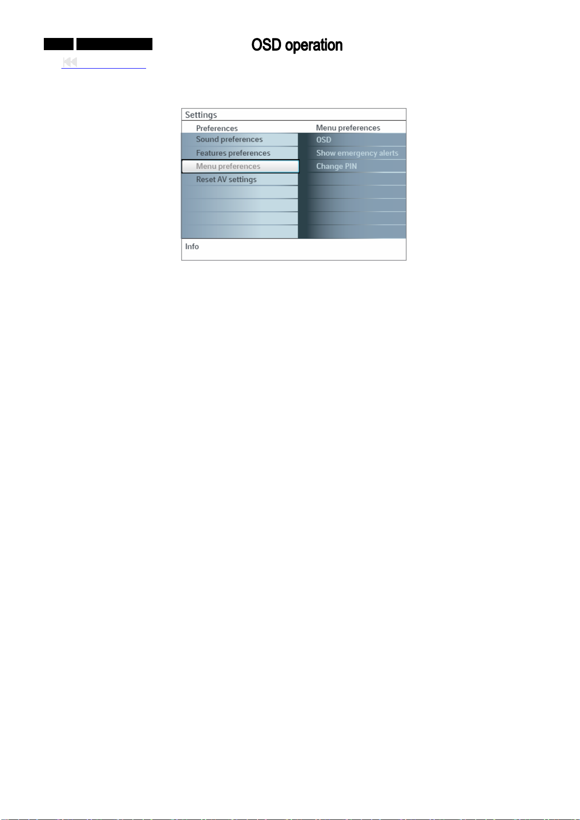
¾ MENU Preferences
1). OSD
lect OSD.
. ① Se
②. Press the curs
or right key to select Normal or Minimum. Normal activates a continuous display of
the channel number for a maximum of 10 minutes and extended display of TV channel and
program information on screen. For example, information on the main or auxiliary program, in
signal quality of connected accessory devices, the display format, sound mode, availability of
Closed Caption service, the audio language, the rating, sleep timer setup is displayed.
Minimum activates the display of reduced channel information.
Not the channel number and clock
e: 1. When Closed Captions is switched on, continuous display of
is not possible.
2. E Signalling is not possible:
mergency Alert
- when content browsing;
- with analogue video sour
ces.
). Show emergency alerts(EAS)
2
This allows you to select the alert prior
ity level of the information disseminated by the cable operator.
The standard SCTE18 defines an Emergency Alert signalling method for use by cable TV systems to
signal emergencies to digital devices such as digital set-top boxes, digital TVs and digital VCRs.
The Emergency alert signalling scheme defined in the standard allows a cable operator to
disseminate emergency alert information related to state and local-level emergencies and w
in a cost-effective and efficient way, while minimizing disruption of programming.
An Emergency alert message will have one of the following priorities: Low, Medium
Maximum.
The Emerge
ncy alert message with priority High or Maximum will always be presented. Low or
Medium will be present or ignored depending on the setting you select.
Important: When the TV clock is undefined (See Setup menu, Clock), the Emergency Alerts will be
ignored.
put
arnings
, High or
Page 32
The Emergency Alert message display will contain following information:
- The Emergency Alert text
- The start time + date
- The end time + date.
① cy Alerts in the Menu preferences menu.
. Select Show Emergen
. ② Press the cursor right key and select one of the Emergency alerts
- Always: You always want available Emergency alert messages to be disp
- Skip low priority: You want low level messages to be ignored;
- Skip low/medium priority: You only want the high priority messa
Notes:
- You al
ways have the possibility to remove the message from the screen.
- The message display will overlap whatever menu element or other messa
3). Se Change PIN
t/
. ① Select Set or
Change PIN with the cursor down.
. ② If no PIN-code exists, the menu item is set to Set
Follow the instructions on screen. If a PIN-code has pr
set to Change PIN. Follow the instructions on screen. All number combinations from 0000 to
9999 are valid numbers.
③. u reappears with a message confirming that the PIN has been
The Menu preferences men
created.
Important: you have forgotten your PIN!
.
①
Select Change PIN in the Menu p
.
②
Press the cursor right key to enter the overriding PIN code 0-7-1-1.
.
③
Press the cursor again and enter a new personal 4-digit PIN code. T
and your new PIN-code is stored.
0-32-0 042MF231D/370
Back to cover
options:
layed;
ge to be displayed.
ge is on the screen.
PIN.
eviously been entered, the menu item is
references menu and press the cursor right key.
he previous code is erased
Page 33
0-33-0 042MF231D/370
Back to cover
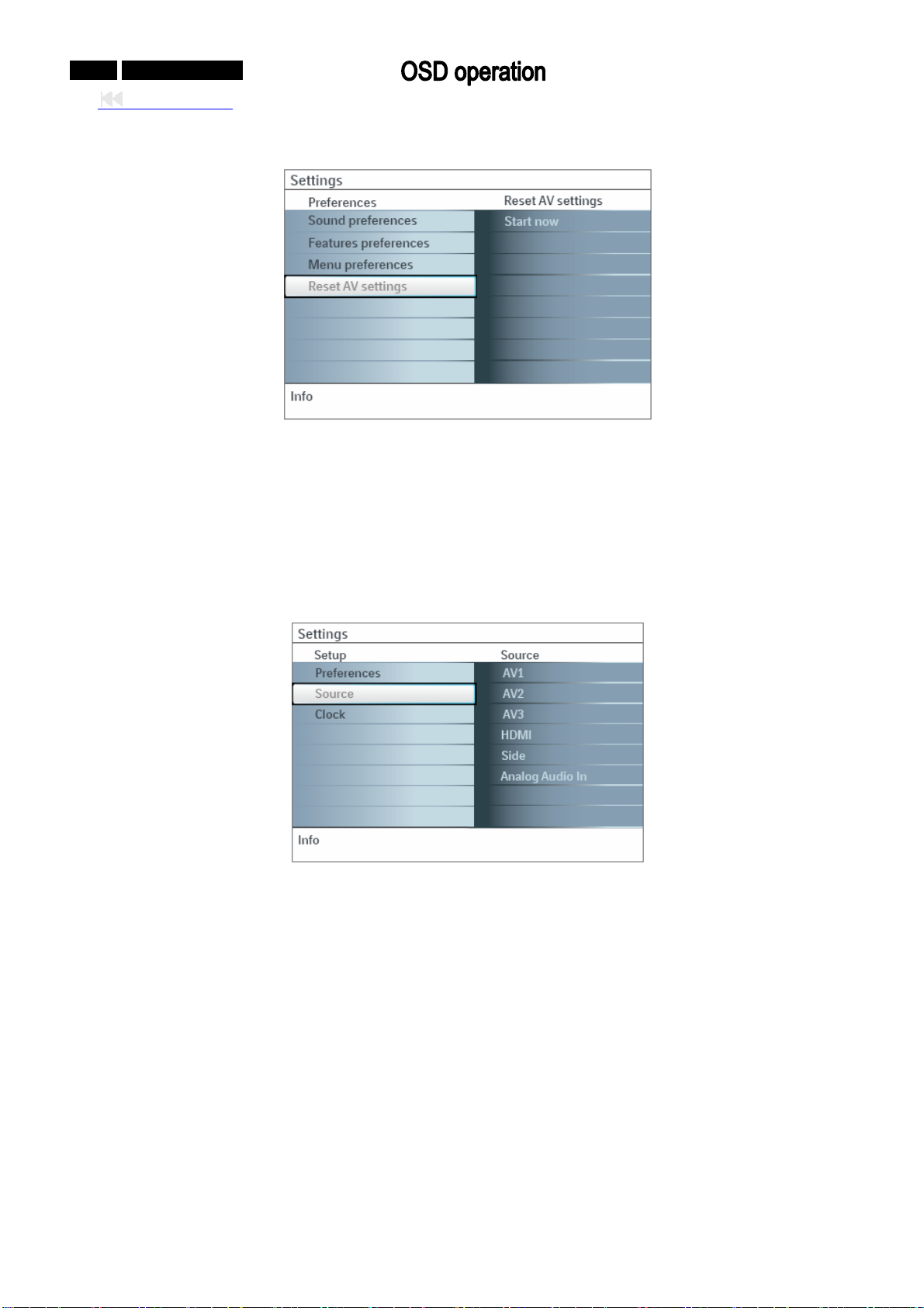
¾ Reset AV settings
This function allows you to reset most of the picture and sound settings t their default factory levels.
①. Select Reset AV settings with the cursor down key.
②. Press the cursor right key.
③. Press the OK button to eras
2. Source
This me
nu allows you to identify the accessory devices you have connected to the external inputs
/outputs.
o
e settings and reset them to their default values.
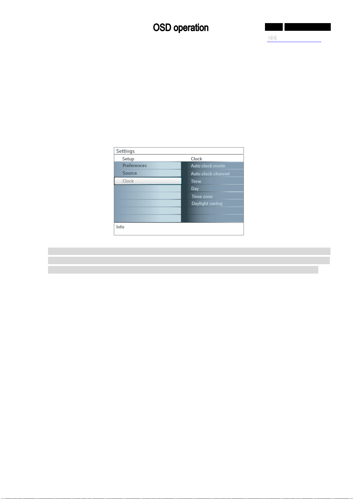
¾ Source(AV1,AV2,AV3,HDMI,Side)
. ① Select Source in the Setup men
. ② Press the cursor right to enter the l
. ③ Select the accessory device with the cursor up/down.
When you select AV1, AV2, AV3, HDMI1, Side or Analo
identify which type of accessory device is attached to this input. The TV detects the presence of
the connected device and the signal is routed appropriately.
¾ Analog Audio In
If your accessory
device has a DVI output connector, only the video signal is transmitted in digital
format. To input an audio signal, please connect the analog audio L and R outputs to the TV’s L and
AV1 audio input plugs. To activate the audio function, select HDMI from the Analog Audio In menu to
activate.
u.
ist of types of devices connected to the selected input.
g Audio In, a list appears allowing you to
R
Page 34
0-34-0 042MF231D/370
Back to cover
¾ igital Audio Out
D
In addition to acce
pting audio input through HDMI, the TV can output Digital audio through the
DIGITAL AUDIO OUT (SPDIF OUT) connector to an external amplifier or receiver. If your amplifie
receiver has a matching connector for Digital Audio In, you can connect it with a single cable to the
TV’s DIGITAL AUDIO OUT (SPDIF OUT).
3. Clock
llows you to use your TV as a clock.
This a
N correct operation of Lock after (See TV settings, Channels)
ote: Adjusting the clock is necessary for the
features.
r or
Most TV channels do not transmit clock information. A few cable channels do, but they are at the end
of the channel ring. Antenna channels do not transmit clock information. If clock information does not
appear, you can assume that either clock extraction is taking a long time or that there is no clock.
Auto clock mode ¾
①. Select Clock in
②. Press the cursor right key to select
③. Press the cursor right key to instruct the TV to get the time
the Setup menu.
the Auto clock mode.
automatically or manually.
¾ Auto clock channel (only available when Auto clock mode is set to Automatic)
With the cursor buttons, select the channel number where time can be found by
can be found on PBS as well as some other channels.
Note: If Manual has been selected in the Auto clock mo
de, the Auto clock channel menu item can not
be selected.
¾ Time - Day (only available when Auto clock mode is set to Manual)
With the cursor buttons, select and enter the correct time and day. I
been selected, and no clock search has been done, the system will keep the entered time and day.
¾ Time Zone (only available when Auto clock mode is set to Automatic)
①. This function allows you to select your local time zone.
②. Broadcasted time information will correct the clock disp
lay for your local time.
Select Time zone with the cursor down.
Press the cursor right to select your loca
l time zone.
the TV. Typically time
f Auto clock mode Manual has
Page 35
0-35-0 042MF231D/370
Back to cover
¾ Daylight saving (only available when Auto clock mode is set to Automatic)
Daylight saving time is automatically set by specially broadcasted signals. T
to disable the automatic setting of daylight saving time. This is useful if you live in an area or state
where daylight saving is not applied, but you receive channels from other areas where daylight sav
signals are broadcasted.
①. Select Daylight saving
②. Press the cursor right key to select Automatic
with the cursor down.
for automatic clock correction for daylight saving
time, based on specially broadcasted signals.
③. based on the specially broadcasted signals.
Select Off to disable automatic clock correction
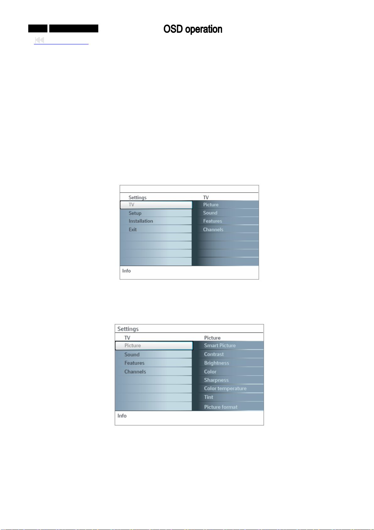
V MENU
T
Press the
MENU button on the remote control to display the Settings menu. The TV menu gives you an
overview of the menus you can select.
his menu item allows you
ing
Note: Depending on the input signal, one or more menu items may not be lectable.
se
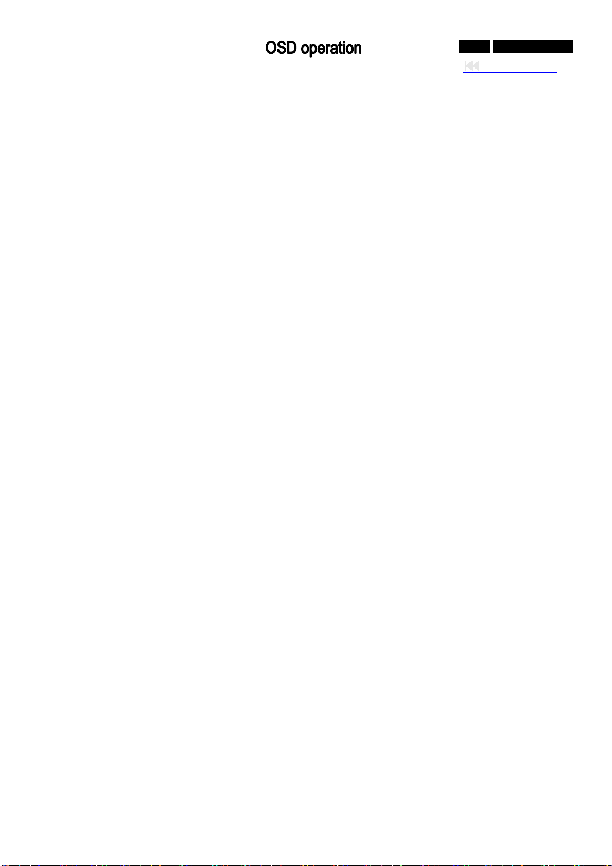
1. Picture
Note: So
me menu items are not available in case of HD sources.
①. Press the cursor right key to select Picture.
②. Press the cursor right key again to enter the Pic
ture menu.
③. Select the menu items with the cursor up/down key.
④. Adjust the settings with the cursor left/right key or ent
er the list of submenu items with the cursor
right key. Select a submenu item with the cursor up/down key.
Page 36
0-36-0 042MF231D/370
Back to cover
¾ Smart Picture
①. Select Sma
rt picture to display a list of predefined picture settings, each corresponding with
specific factory settings. Personal refers to the personal preference settings of picture in the
picture menu.
Note: This Mag
which typically use fluorescent lighting. As your home will likely not be as well lit as a store, we
recommend that you cycle through the various smart picture modes to find the one that best suits
navox TV has been set at the factory to look best in bright store environments,
your own viewing conditions. Most consumers will find that Natural is the correct choice.
②. ou can press the Smart picture button repeatedly to select either Personal, Rich, Natural, Soft,
Y
Multimedia or Eco picture settings.
Note: When you watch programs us
ing VCR, it’s recommended to select Soft Mode via smart
picture.
¾ Con rast
t
This will a
djust the intensity of bright parts in the picture but keep the dark parts unchanged.
¾ Brightness
This will adju
st the light output of the complete picture, which will mainly affect the darker areas of the
picture.
¾ Color
This wi
ll adjust the saturation level of the colors to suit your personal preference.
¾ Sharpness
This will adju
st the sharpness of fine details in the picture.
¾ Color temperature
This will increase or
Select Cool to give the white colors a blue tint, Normal to give the white colors a neutral tint, Wa
decrease Warm (red) and Cool (blue) colors to suit personal preferences.
rm to
give the white colors a red tint.
¾ Tint
s you to select the picture ‘s color mix or hue.
Allow
¾ Picture format
This menu item
performs the same as the FORMAT button on the remote control.
Page 37
0-37-0 042MF231D/370
Back to cover
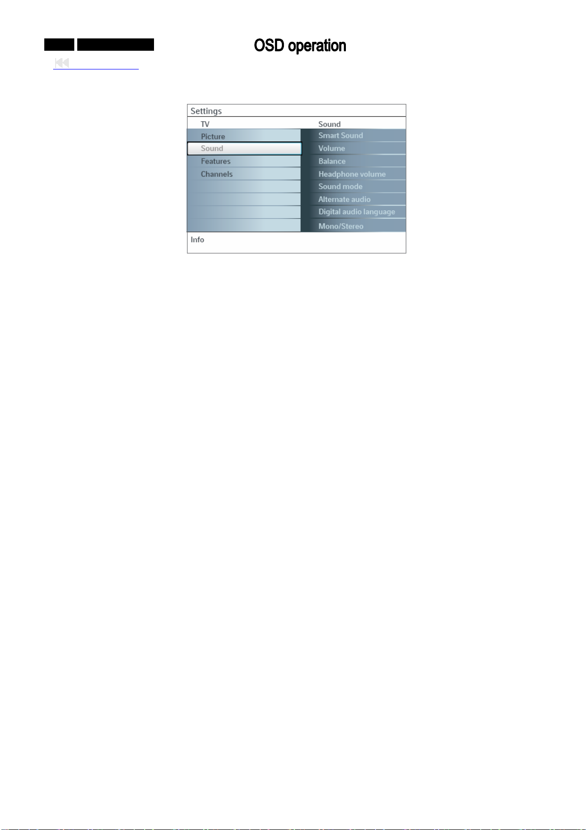
2. Sound
①. Select Sound in the TV Settings menu.
②. Press the cursor right key to enter the so
und menu.
③. Select the menu items with the cursor up/down key a
key.
④. mber, control settings are at normal mid-range levels when the bar scale is entered.
Reme
¾ Smart sound
Select Smart s
ound to display a list of predefined sound settings, each corresponding with specific
factory settings of Treble and Bass. Press the cursor right key to enter the list.
①. Press the cursor up/down key to select a predefined sound setting.
②. Personal refers to the personal preference sound settings in the soun
ote: The moment you are in a predefined Smart sound setting and you modify a setting in the Sound
N
menu, all values of the menu will overwrite the previously made personal setting.
¾ Volume
This will a
djust the sound output level.
¾ Balance
This will a
djust the output of the right and left speakers to obtain the best stereo reproduction for your
listening position.
¾ Headphone volume
This controls the leve
l of sound through the headphones.
¾ Sound mode
This select the
modes for more spatial or surround sound reproduction dependent on the broadcast
signals or signals from external inputs received.
¾ Alternate audio (only selectable with analog broadcast signals)
This gives you the possibility to swap between the Main and Sec
available.
nd adjust the settings with the cursor left/right
d menu.
ond Audio Program (SAP) when it is
Page 38
0-38-0 042MF231D/370
¾ Digital audio language (only selectable with digital broadcast signals)
Selects your language preference when digital broadcast signal multilingu
al audio track programs are
available.
Note: The d
efault language for the digital channels is the installed menu language.
¾ Mono/Stereo
Selects per TV
channel, Mono or Stereo sound when analog stereo broadcasts are available.
¾ AVL(Automatic Volume Leveler) (only available with analog broadcast and non-Digital signals)
Automatically reduces the volume differences between channels and programs, providing a mo
constant overall level. This will also reduce the dynamics of sound.
¾ Delta volume
Corrects for an
y permanent volume differences between TV channels or external sources.
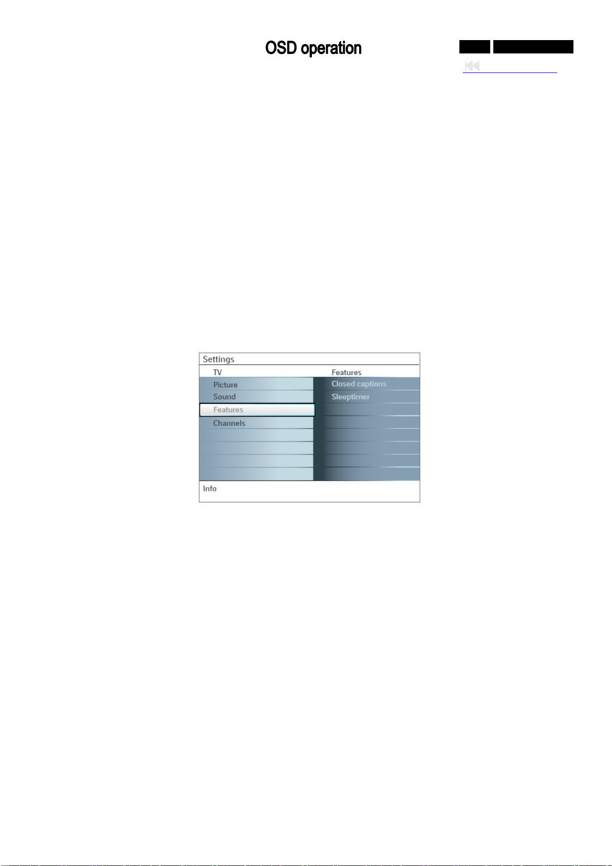
3. Features
Back to cover
re
. ① Select Features in the TV Settings menu. Press the cursor right key enter the features menu.
. ② Select the menu items with the cursor up/down key and adjust the settings with the cursor left/rig
key.
¾ Closed captions
This displays the tr
in the Setup menu, Features preferences menu. This text can either be permanently displayed
(assuming that the service is available in the broadcast) or only when mute is active.
①. Press the cursor right key after having selected Closed captions.
②. Select On, Off or On during mute.
¾ Sleeptimer
This sets a ti
①. Select Sleeptimer.
②. Press the cursor rig
③. Select a value with the curs
ansmitted CC- or CS-text on the screen according to your chosen CC or CS service
me period after which the TV automatically turns to standby.
ht key.
or up/down key. The list will have values from Off to 180 minutes.
When Off is selected, the sleeptimer is turned off.
You can always turn off your TV earlier or select an
other time set.
to
ht
Page 39
0-39-0 042MF231D/370
Back to cover
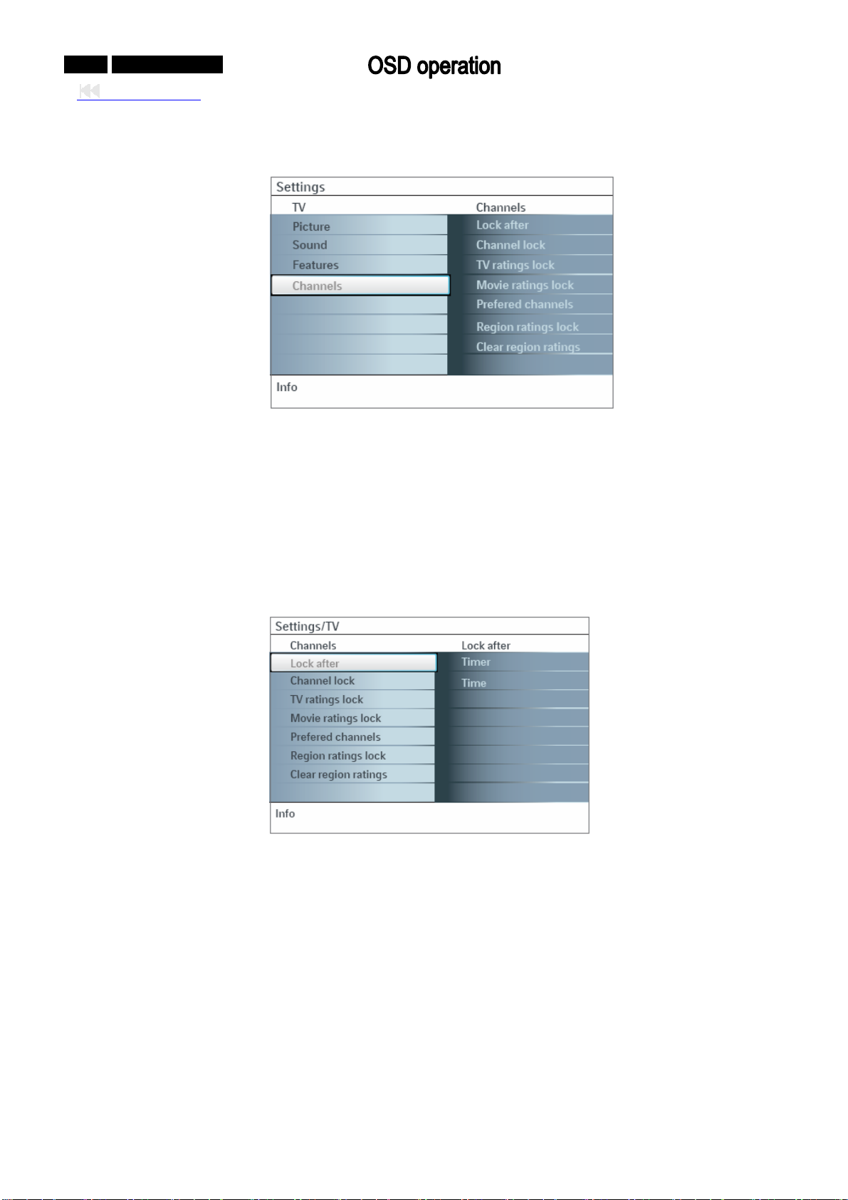
4. Channels
can control special functions for the TV channels. This menu
①. Select Channels in the TV settings menu with the cursor up/down key.
②. Press the cursor right to enter the channels menu.
③. Press the cursor up/down key to select a channels menu i
¾ Lock after
Note: Lock
after is only selectable if time and date are known. See Setup, Clock menu.
This allows you to prevent the viewing of the channels after a selectable time delay.
channels can still be tuned, but the picture is blanked and the audio is muted.
tem.
Locked
①. Press the cursor right and select Timer On or Off.
②. ursor right. This allows you to set the time after which the lock is set.
③. Select AM or PM to select the correct period of the day.
④. Enter the time with the digit or the cursor buttons and pre
Channel lock
¾
This allows you
subchannels you want to lock and press OK to confirm.
When set to On this allows you to set the clock.
When having selected Timer On, you will be aske
the instructions on screen.
Select Time and press the c
to completely lock a certain TV channel or external source. Select the channels or
d to enter your PIN (See Set/Change PIN). Follow
ss OK to confirm.
Page 40
0-40-0 042MF231D/370
Back to cover
TV ratings lock
¾
Your TV is equip
ped with a V-chip. This allows you to control access to individual programs based on
their movie and TV ratings. All settings apply to all AV inputs, except HDMI. The program content
advisory data are sent by the broadcaster or program provider.
①. Select TV ratings lock with the cursor down. A list appears, showing the age-based TV ratings
and a corresponding content-based ratings list.
②.
Press the cursor right to enter the list.
③. Select an age-based TV rating with the
cursor up/down, and enter, if present, the list with
content-based ratings with the cursor right, and select one content-based rating.
④. IN-code (see
Press OK to activate/de-activate the selected rating. You are asked to enter your P
Set/Change PIN, p. 18). If the code is correct, the TV ratings lock menu reappears.
⑤.
Select another content-based rating if you like and press OK again.
You need only enter your PIN-code once while the menu is active. You can lock/unlock any number of
ratings on the list without re-entering your code.
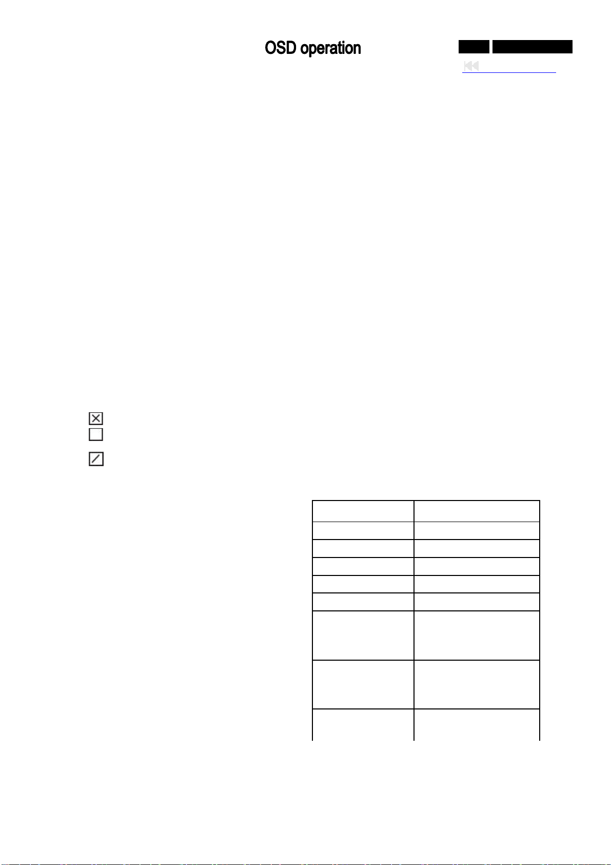
ach ratings item has a box-graphic in front of it to indicate whether or not programs carrying that
E
rating are currently locked:
: all items in the contents-based list are locked as well;
: the item is unselected;
: some content-based ratings are selected/unselected.
W All has been selected, all items in the
hen
Age-based Rating Content-based Rating
e
that
All none
None none
TV-Y none
TV-Y7 (FV) Fantasy Violence
TV-G none
TV-PG (D) Dialog (L)
ex (V) Language (S) S
Violence
TV-14 L)
(D) Dialog (
Language (S) S
ex (V)
Violence
TV-MA L)
(D) Dialog (
Language (S) S
ex
age-based and in the contents-based lists ar
locked. If, while All is selected, any other item,
either an age-based or content-based item, is
unselected, then All is automatically
unselected.
one is the selection for items that either have no
N
rating information or have a rating of None.
Both will be locked. When an item on the
age-based list is selected, all items below
item of the same group are locked as well.
When you select a content-based rating, all
identical content- based ratings in the
younger age-based categories are also
selected.
Page 41
0-41-0 042MF231D/370
Back to cover
TV-Y appropriate for children of all ages with themes and elements suitable for
children aged 2-6
TV-Y7 programs designed for children age 7 and older
TV-Y7-FV
TV-G
programs include fantasy violence more intense than other programs in the
TV-Y7 category
programs suitable for all ages. These programs contain little or no
violence, no strong language and little or no sexual dialogue or situations
programs contain elements that some parents may find unsuitable for
TV-PG
younger children and which may need parental guidance. The program
may contain moderate violence, sexual dialogue and/or situations and
some strong language.
programs contain elements that may not be suitable for children under 14
TV-14
years of age. These programs include one or more of the following: intense
violence, intense sexual situations, suggestive dialogue and strong
language.
programs are designed to be viewed by adults and may be unsuitable for
TV-MA
children under the age of 17. These programs may contain graphic
violence, explicit sexual activity and/or crude or indecent language.
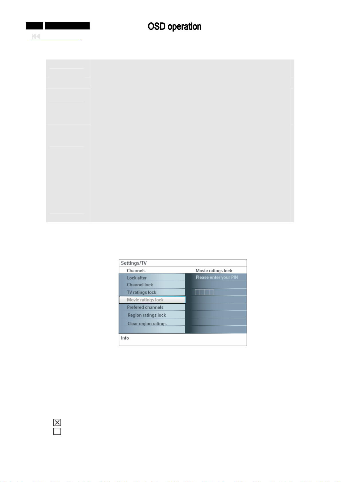
Movie ratings lock
¾
This function allows
you to control access to individual movies based on their MPAA ratings (Motion
Picture Association of America).
①. Select Movie ratings lock with the cursor down. A list appears, showing all valid MPAA content
ratings.
②. cursor right to enter the list. You are asked to enter your code. (See Set/Change PIN) If
Press the
the code is correct, the Movie ratings lock menu reappears.
③.
Select a movie rating with the cursor up/down.
④. Press OK to activate/de-activate the selected ra
E hether or not programs carrying that rating
ach rating item has a box-graphic in front of it to indicate w
ting.
are currently locked:
•
: movies with this rating are locked;
•
: movies with this rating are unlocked.
Page 42
0-42-0 042MF231D/370
Back to cover
W en All has been selected, all items on the movie ratings list become selected. (All movies are
h
locked.) If, while All is selected, any other item is unselected, then All is automatically unselected.
When NR has been selected, no other item is selected.
When any other item has been selected, all ratings below
are selected as well, thus all movies with
those ratings will be locked.
NR not rated
G movies with a mild content, suitable for all ages
PG movies for which parental guidance is recommended. They may contain a few racy
or violent scenes or maybe some bad language
PG-13R f under age 13 movies for which parental guidance may be recommended i
R restricted. The movies usually contain offensive sex or bad language and may be
unsuitable for children under the age of 17. Parental guidance or permission
needed.
NC-17 ental permission, forbidden under age 17. More offensive sex, violence even with par
or bad language.
X rally focus on sex, violence and/or bad language. Also known as movies which gene
pornography.
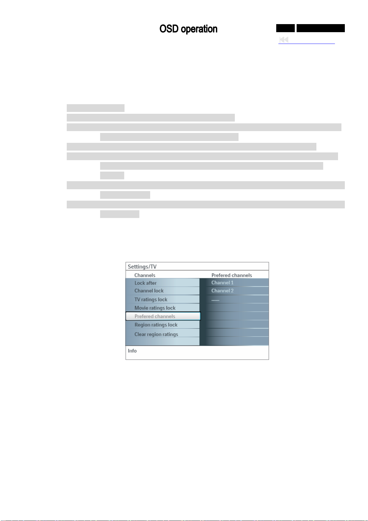
¾ Prefered channels
talled, is marked as preferred by default and added to the channel list. This A channel, when ins
feature provides the ability to remove a channel number from the channel list.
①. Select Preferred channels with the cursor down key.
②. Press the cursor right key to enter a list with all stored
channel numbers.
③. Select the channel you want to remove with the cursor down key.
④. Press OK.
Repeat to r
⑤.
emove other channels.
Note:
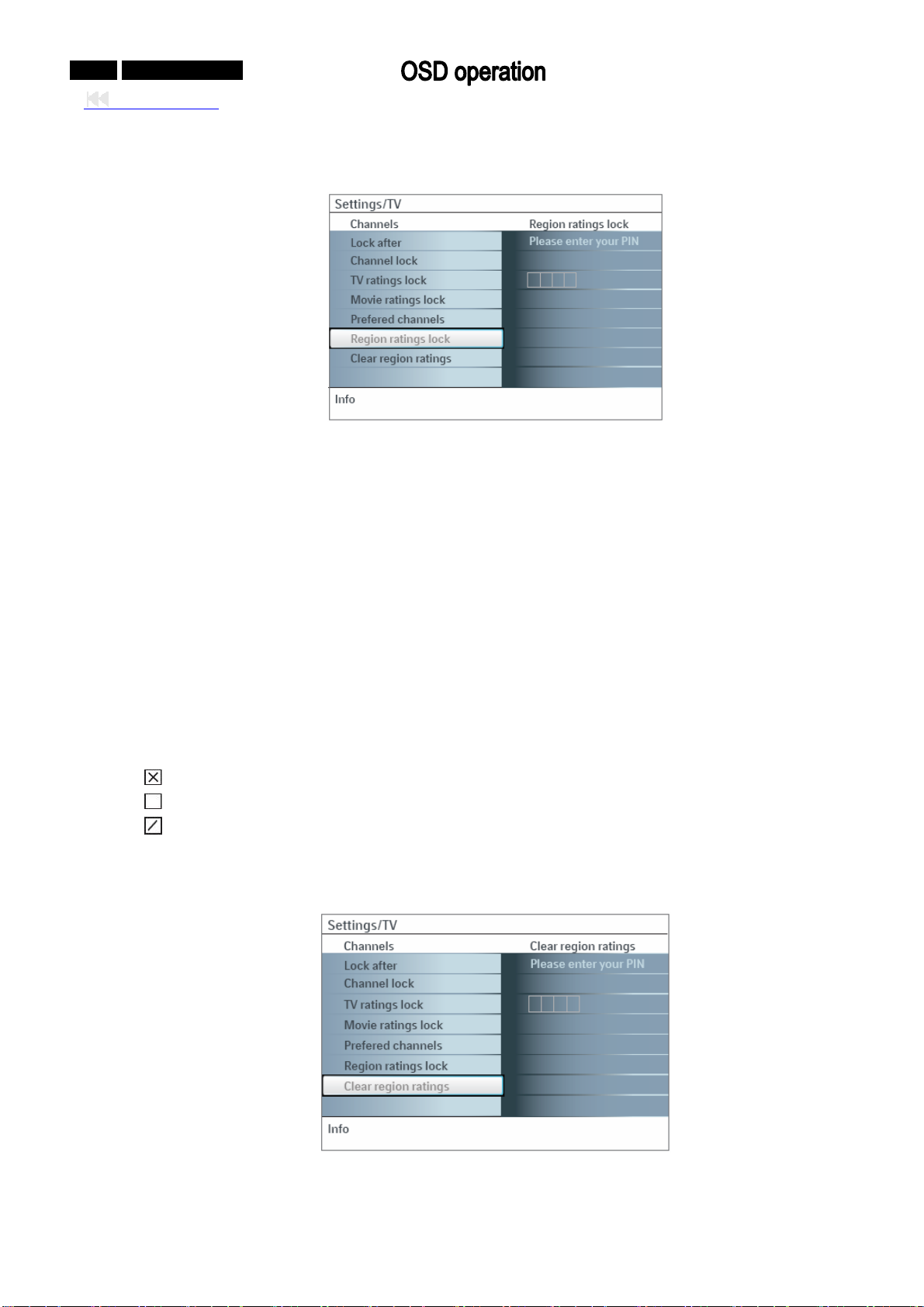
Region
broadcasted regional rating. Clear region ratings: This allows you to clear all the locks that y
ratings lock: This allows you to control access to individual programs base on their
ou have
set in the Region ratings lock table.
Page 43
0-43-0 042MF231D/370
Back to cover
Region ratings lock
¾
This allows you to co
①. Select Region ratings lock with the cursor down. A list appears, sho ing the age-based Region
ratings and a corresponding contentbased ratings list.
②.
Press the cursor right to enter the list.
③. Select an age-based Region rating with
content-based ratings with the cursor right, and select one content-based rating.
④. IN-code (see
Press OK to activate/de-activate the selected rating. You are asked to enter your P
Set/Change PIN, p. 17). If the code is correct, the Region ratings lock menu reappears.
⑤.
Select another content-based rating if you like and press OK again.
You need only enter your PIN-code once while the menu is active. You can lock/unlock any number of
ratings on the list without re-entering your code.
ach ratings item has a box-graphic in front of it to indicate whether or not programs carrying that
E
rating are currently locked:
•
: all items in the contents-based list are locked as well;
•
: the item is unselected;
: some content-based ratings are selected/unselected.
•
¾ lear region ratings
C
This allows you to cle
ntrol access to individual programs base on their broadcasted regional rating.
w
the cursor up/down, and enter, if present, the list with
ar all the locks that you have set in the Region ratings lock table.
①. Select Clear region ratings with the cursor down.
tus. ②. Enter your PIN-code to clear all region ratings’ sta
Page 44
Symptoms Items to Check and Actions to follow
0-44-0 042MF231D/370
Back to cover
“Ghost”
or
double images
No power
No picture
No picture
And
power switched on
Picture position
adjustment
z This may be caused by obstruction to the antenna due to high rise buildings or
hills. Using a highly directional antenna may improve the picture.
z Check that the TV’s AC power cord is plugged into the mains socket.
z Unplug the television, wait for 60 seconds. Then re-insert plug into the mains
socket and turn on the television again.
z Check antenna connections at the bottom of the TV to see if they are properly
connected to the TV.
z Possible broadcast station trouble. Try another channel.
z Adjust the contrast and brightness settings. Try another auto picture setting.
z Check the Closed Captions control. Some TEXT modes could block the
screen.
z Check if you selected the correct AV source.
z Your TV has a protective mode in case there is too much heat build-up. Check
the clearance around the vents of the device to be certain there are no
blocking walls or cabinets which would limit the air flow.
When displaying a High Definition signal from the YPbPr inputs or HDMI input, if
necessary, you can adjust the picture position to the center of the screen with the
cursor left/right or up/down buttons on the remote control. This may be needed
due to slight differences in output signals from different brands and types of HD
sources boxes.
Notes: Most High Definition receiver boxes also have picture-positioning controls
in their menu systems. If the TV cursor controls run out of range before the picture
is correctly positoned, the receiver box controls will need to be adjusted.
No photo, music or
video play or in poor
quality only
No sound
Good sound
but poor color
or no picture
Snowish picture
and noise
Television not
responding
to remote control
z Check if the source complies with a supported code.
z Increase the VOLUME.
z Check that the TV is not muted, press the MUTE button on the remote control.
z When no signal is detected, the TV automatically switches off the sound. This is
proper operation and does not indicate a malfunction.
z Adjust the contrast, color, tint and brightness setting. Try another auto picture
setting.
z Check the antenna connection.
z Check whether the batteries are working. Replace if necessary.
z Clean the remote control sensor lens on the monitor.
z Operating range between TV and the remote control should not be more than
approximately twenty feet.
z You can still use the buttons on the right side of your TV.
z Check if the remote control is in the correct mode.
Page 45
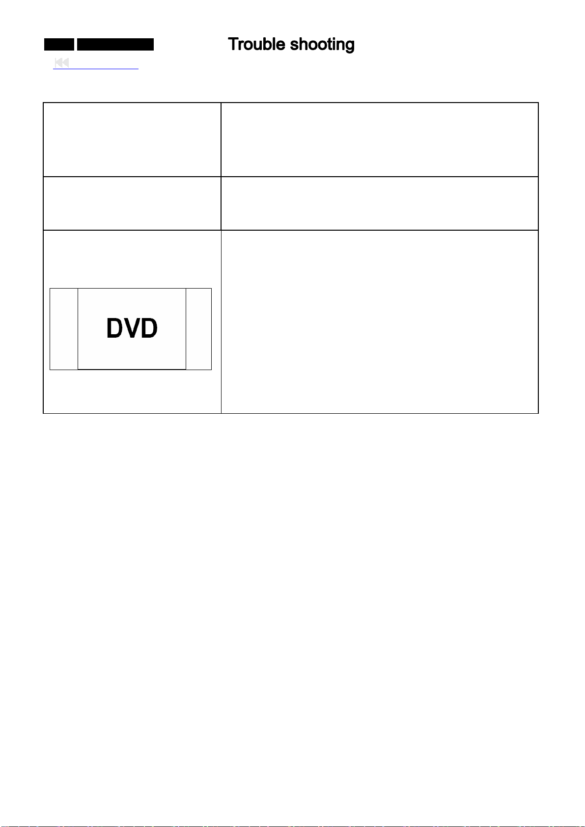
0-45-0 042MF231D/370
Back to cover
Control of accessory devices
The software will not install
After-images appear
The infrared signals of the screen may influence the reception
sensibility of other peripherals Solution: replace the batteries of the
remote control of other devices. E.g. keep away a wireless
headphone from within a radius of approximately four feet.
Possibly the operating system is wrong. Go to
www.usasupport.magnavox.com to see which operating systems
are supported.
Do not allow a still picture to be displayed for an extended period,
as this can cause a permanent after-image to remain on the
Plasma TV.
Examples of still pictures include logos, video games, computer
images, and Teletext.
Note:
The permanent after-image on the Plasma TV resulting from fixed
image use is not an operating defect and as such is not covered
by the Warranty.
This product is not designed to display fixed images for extended
periods of time.
Page 46
No display
No display
Check PANEL internal mode (white
screen) whether normal?
The method of enter into internal mode is:
1. short the CN20722 on logic board;
2. short the Relay and GND pin in CN80
0;
3. Plug in power cord
OK
Check the voltage of 1001 port :
NG
PIN1, 2=16V
PIN3 = STB5V
OK
Check the all voltage on main
NG
board whether normal?
OK
Measure the frequency of:
1H00=27MHZ?
NG
1LA0=16MHZ?
1T11=25.14MHZ
?
OK
Check 1403 LVDS Port, LVDS wire
and peripheral circuits whether
have short or bad solder.
OK
0-46-0 042MF231D/370
Back to cover
NG
Repair the PANEL module
Check the CN902 of OFPB board:
PIN1,2=16V
Checking correlative power circuit
Check the two capacitances of
every Crystal oscillators, if normal
replace the crystal oscillator.
Page 47
0-47-0 042MF231D/370
g
Back to cover
DMI block
H
Measure the below voltage:
IB66 =3.3V;
IC 7B50: Pin103,11,140,154,156=1.8V
1. Measure the voltage of PNX2015 whether
2. the frequency of 1LD6 =16Mhz?
3. Measure PNX2015 peripheral circuit wheth
1. Measure the voltage of PNX8852 whether
2 the frequency of AH11 =27Mhz?
. Measure
3.Check PNX8852 peripheral circuit whethe
HDMI mode abnormal
Test 1I06 Port Pin whether have short or
bad solderin
. Measure 5B00 voltage
=5V? Measures the PIN of IC 7B02 and
check peripheral parts whether have
short, bad soldering and so on.
Pin106,147,64,70,75,77,83,85,
92,98,1
01,104,3,13,21,29,37,45,53,188,196,62
,157,163,169,175,181=3.3V
normal?
Measure
have short, bad soldering and so on.
normal?
short, bad soldering and so on.
er
r
Page 48
ideo block
V
S-VIDEO no color
Measure FI0J point signal
whether normal
OK
Check the signal of IC
7A00 at PIN5 whether
OK
Measure the voltage of IC
PNX3000 at pin49,64,14,28,
35, 42, 39,110=5V?
OK
1. Check the voltage of IC
PNX2015 is normal?
2. y of
Measure the frequenc
1LD6 =16Mhz?
3 X2015
.Check the IC PN
peripheral parts whether
have short or bad soldering
OK
1.Check the voltage of
PNX8852 is normal?
2 y of
.Measure the frequenc
AH11 =27Mhz?
3 X8852
.Check the IC PN
peripheral parts whether
have short or bad solder.
NG
NG
NG
0-48-0 042MF231D/370
Back to cover
Replacing S-VIDEO input port
Check 5809, 3I0N and 2A16
whether have short, bad solder?
Check correlative power circuit
Page 49
0-49-0 042MF231D/370
Back to cover
V block
T
TV (NTSC) No Sound
Check the voltage of
1T04 at PIN2=5V?
Check the signal of IA46
whether normal?
Check the voltage of
U3=5V, and check the IC
of 7A11 peripheral parts
whether have short or
bad soldering.
Check the voltage of
IA03=5V, and IA04 =8V
OK
OK
OK
OK
NG
NG
NG
NG
Check correlative power circuit
Check 5A18 and 2A90 whether
have short or bad soldering.
Checking 5V power circuit.
Check correlative power circuit
Page 50
:16
C power block
D
Check the connector(1001) Voltage
input :
PIN1:16V
PIN2
V
OK
Measure the Voltage input as follow:
1U01→12V
7U28→2PIN
=3.3V
7U28→3PIN=2.5V
7U00→11PIN=1.2V
5002→5V
7U25→5,6,
7U25→1,3PIN=5V; 2,4PIN=
7,8PIN=STB5V
12V
7U03→5,6PIN=12V;4PIN=2.5V
7U01→7,8PIN=12V;1,6PIN=3.3V
;2PIN=5V;4PIN=8
V
03→1PIN=12V;4PIN=1.8V;5PIN=1.2V;6PIN=3.3
70
V;
OK
NG
0-50-0 042MF231D/370
Back to cover
Check the
correlative circuit
Page 51
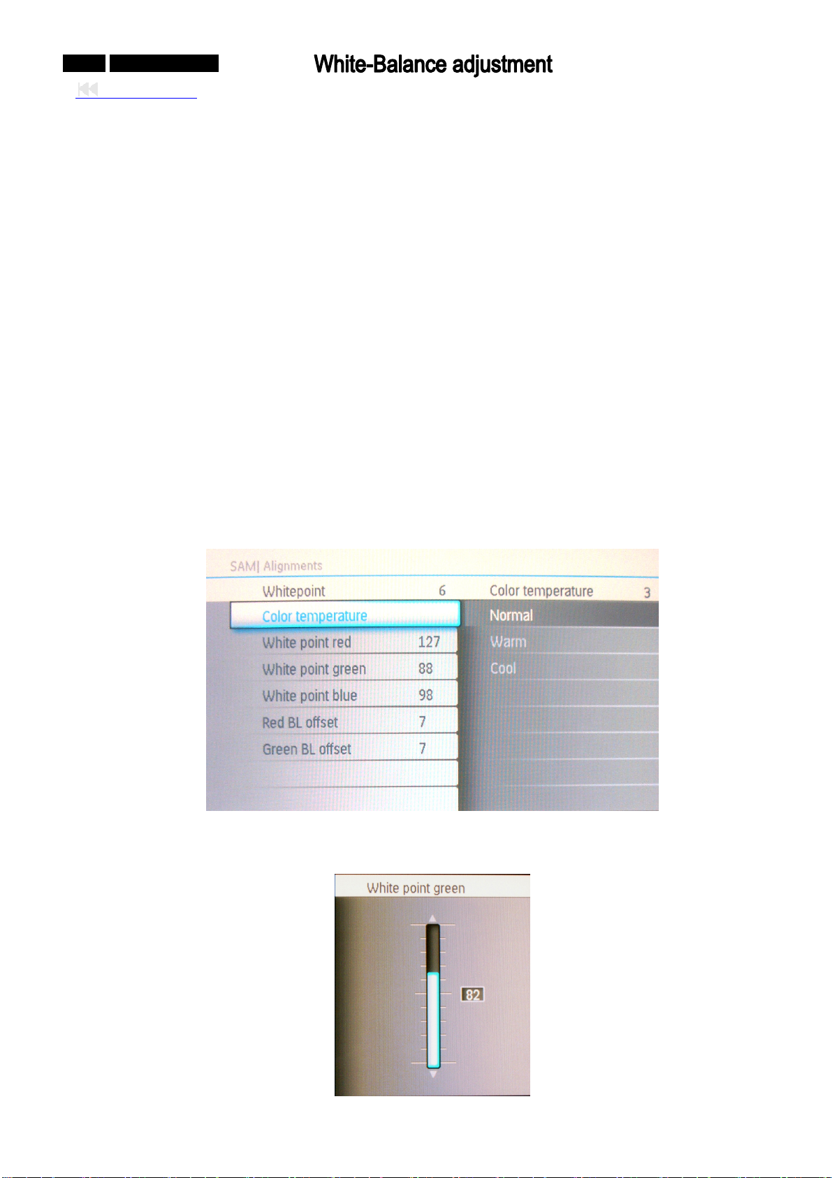
0-51-0 042MF231D/370
Back to cover
In case the white-balance data memory IC or main EEPROM which storage all factory settings were
replaced due to a defect, the data have to be re-adjust.
It is advised to re-soldered DDC IC and main EEPROM fro
m the old board onto the new board if circuit
board have been replaced, in this case the white-balance data does not need to be re-adjust.
Equ
ipments list
Chroma
7100 1set
Fluck54200 video signal generator 1set
RF cable 1pcs
Preparat
ion and Adjustment process
1. Preparation:
z Connect rear
z The setting of Fluck54200 is 187.25Mhz(80db,
RF port of PDP with Fluck54200.
White pattern).
z Turn power of PDP and test instrument on.
z Before open lens, Press O-CAL of Chrom-71
00 and revise lens.
2. Adjustment process
a). Press the “062596
” and INFO key(Red key) with IR Remoter in TV mode, there is a warning OSD
displayed.
b). I menu, select “Alignments -> Whitepoint”
n the factory
c). There are “Color temperature”, “White point red”, “White point green”, “White poin blue”, “Red BL t
offset” and “Green BL offset” items which can be adjusted.
Page 52
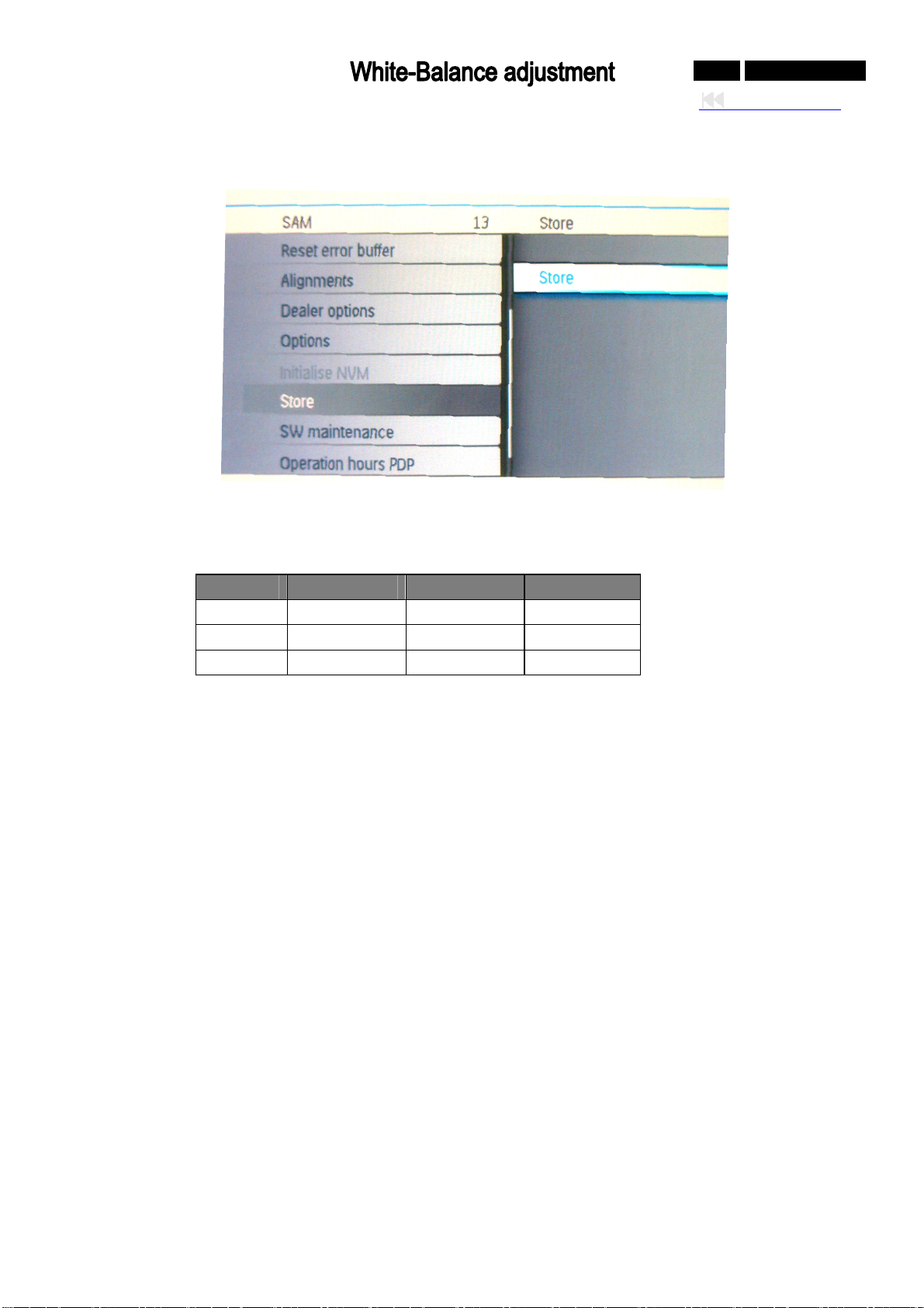
0-52-0 042MF231D/370
Back to cover
d). After adjust the items, go back to the factory main menu, press DOWN to next page, and select
“Store”, press “OK” key, then the OSD will show “store completed”.
e). Reboot the ed.
TV set, the white balance setting is
chang
Adjustment stand of white Balance:
Normal Coo l Warm
CCT 10900º K 13500 K 6500º K º
x 276 ± 5 267 ± 314 ± 5 5
y 283 ±.5 272 ± 324 ± 5 5
Page 53
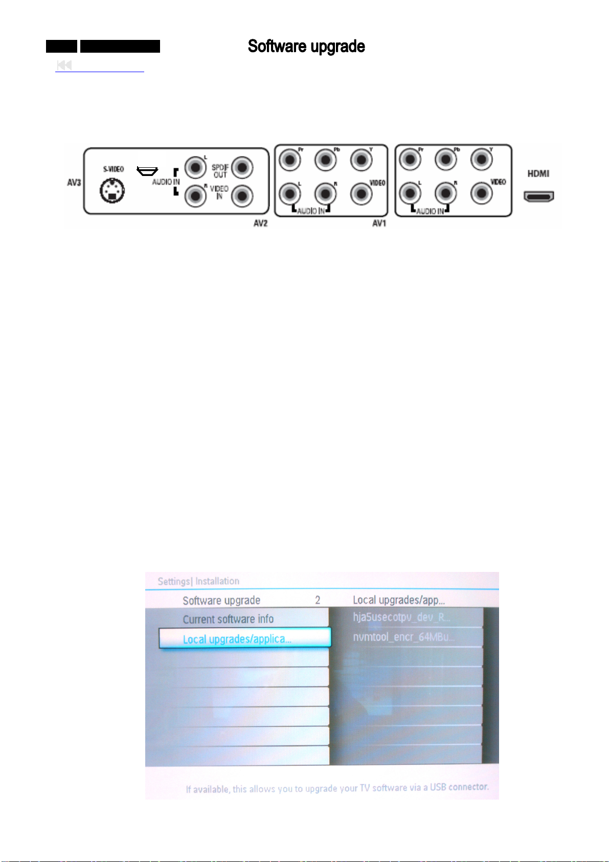
0-53-0 042MF231D/370
Back to cover
terface
In
: Not support : Supported 1. RS232 [ ] 2. USB [ ] 3. RF [ⅹ√ ⅹ√]ⅹ
USB
USB interface is on the back bottom or right bottom of the set.
Software u
Th r the new set.
pgrade
ere are main application software and parameter need to be updated fo
Main Application Soft
The main ap software is copied to Nand Flash via USB.
plication
ware upgrade
1. F e for the main application software upgrade
il
The upg file which you want to be upgraded sho copied to the folder “upgrades” in the root of
USB XX’ of the filename is the revision of
, the file which is named as “hja5usecotpv_dev_RXX.upg”(the ‘
uld be
the software), and the file size is about 9875K.
2.
Upgrade the main application software in normal mode
a) Push the USB in the USB interface
of the PDP TV set.
b) The PDP TV set is in power on mode(normal mode).
c) Enter the user menu, select “Installation->software upgrade->Local upgrades/application” with IR
Remoter, the application will check the softw
are from USB automatically.
Page 54
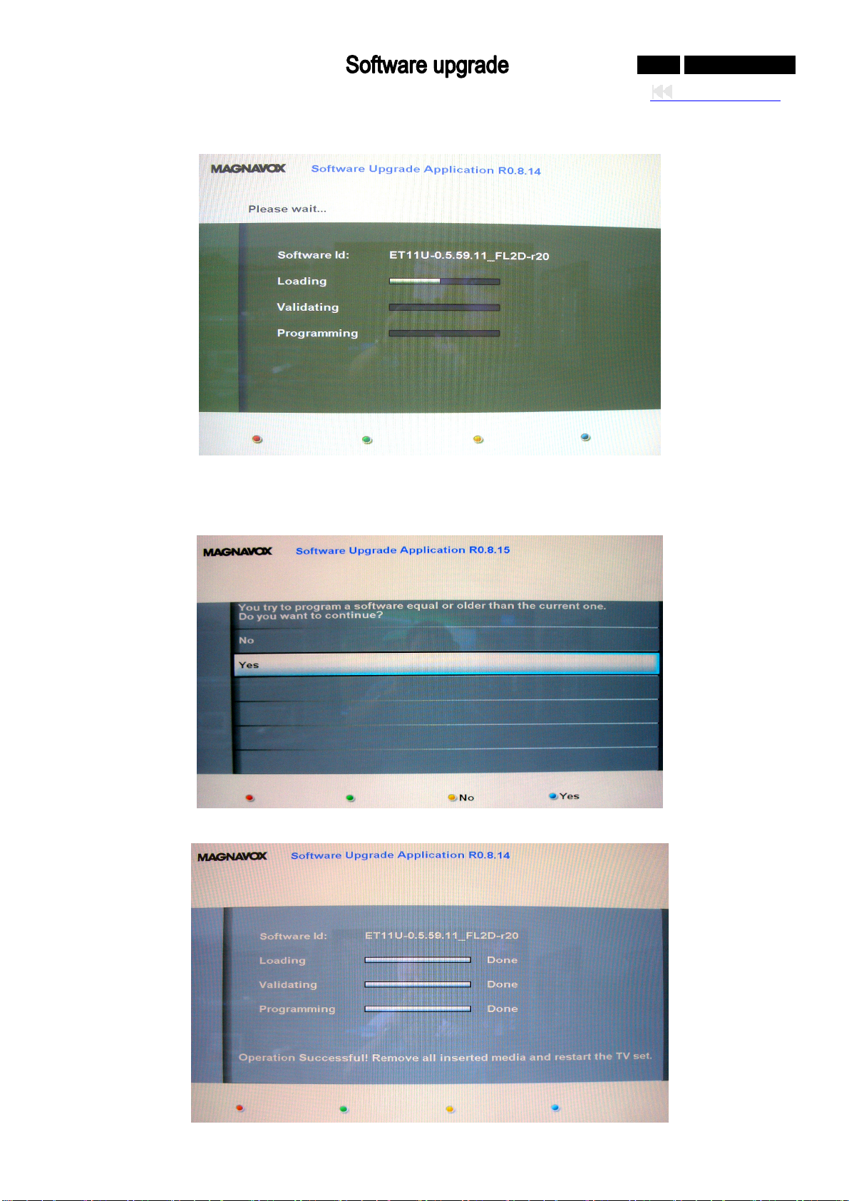
0-54-0 042MF231D/370
Back to cover
d) Select the file you want to update to the TV set and use INFO key with IR Remoter to do “Upgrade
now”.
e) If the software version you selected is equal or older than current one, the OSD for confirmation will be
displayed, choose YES (FORMAT key) to upgrade and No ( key) to cancel the upgrade; else the √
software will be upgraded automatically.
When the upgrade is finished automatically, reboot the set f)
Page 55
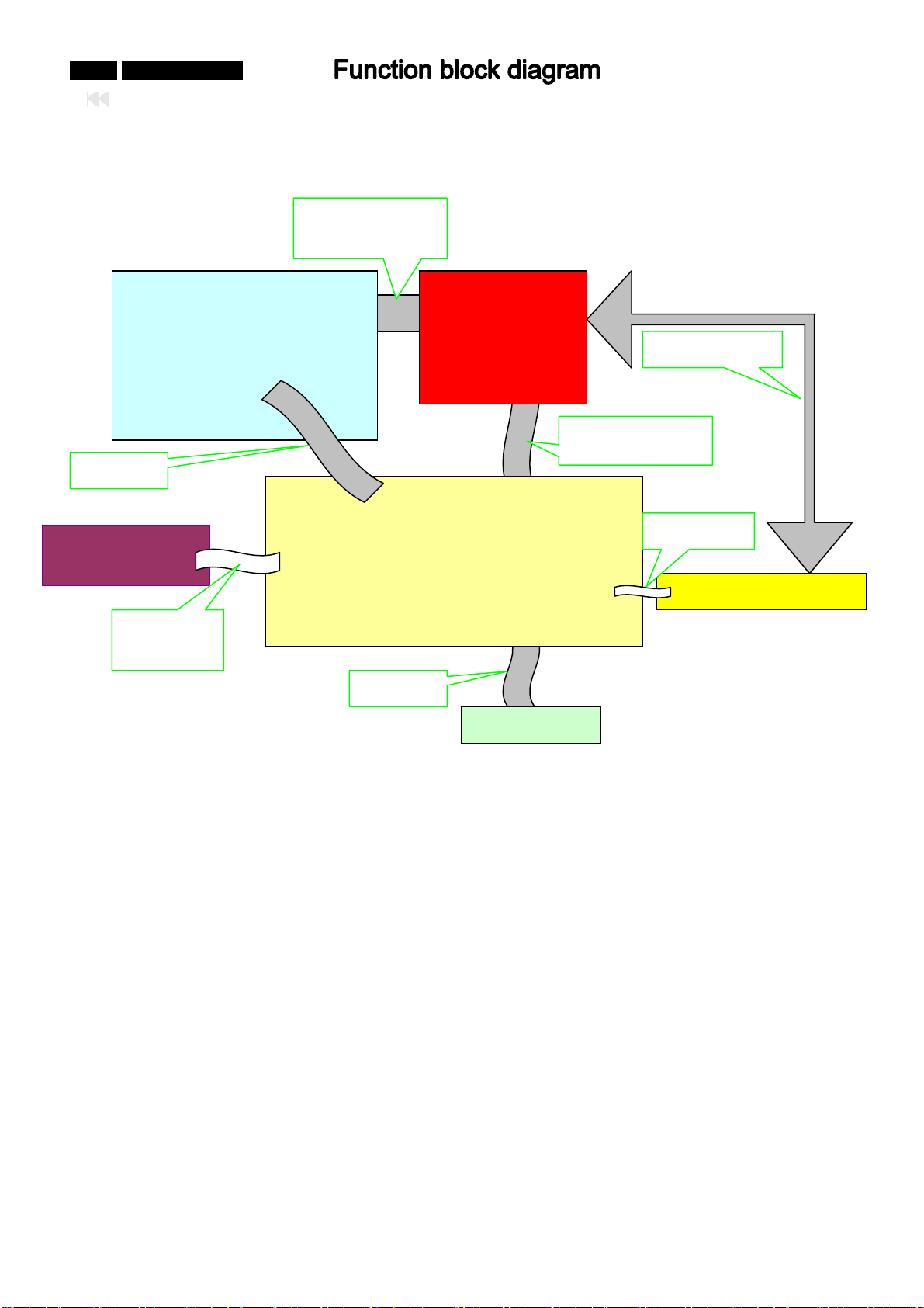
0-55-0 042MF231D/370
Back to cover
PDP unit block diagram and functions
CN5008 to CN8003
CN4001 to CN8086
Panel Module
1403 to
Side AV PCB
1410 to
side
Function of Boards:
1) IMAGE Board : Control all input signals, Decode the video signal, De-interlace, and send digital
signals (LVDS signal) sent from image Board and display
2) PDC Board: Power ard
3) SIDE AV Board: Th rface
e input signal inte
4) Power Board: Supply Power for Panel and Image Board
5) KEY Board: POWER, Signal Source, MENU, CH+, CH - / VOL +, VOL -
Part apt t
o decrease:
1) BEZEL, REAR COVER, STAND& GLASS FILTER
2) Panel and its boards
3) RCA plug
SMPS
CN8001 to CN902
CN904 to 1001
1001 to CN903
Image Board PCB
Power Down Control PCB
Key to 1402
Key Board PCB
Down Control Bo
Page 56
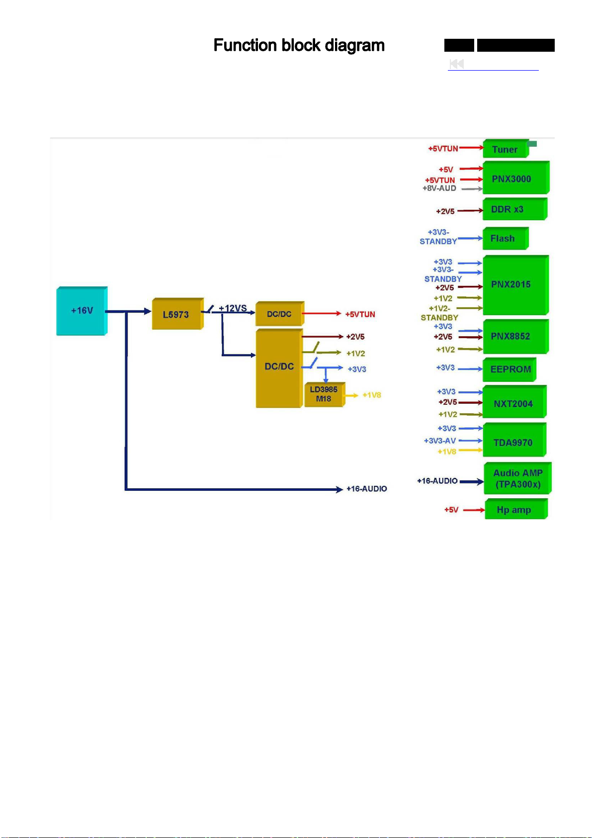
ower management
P
0-56-0 042MF231D/370
Back to cover
Page 57
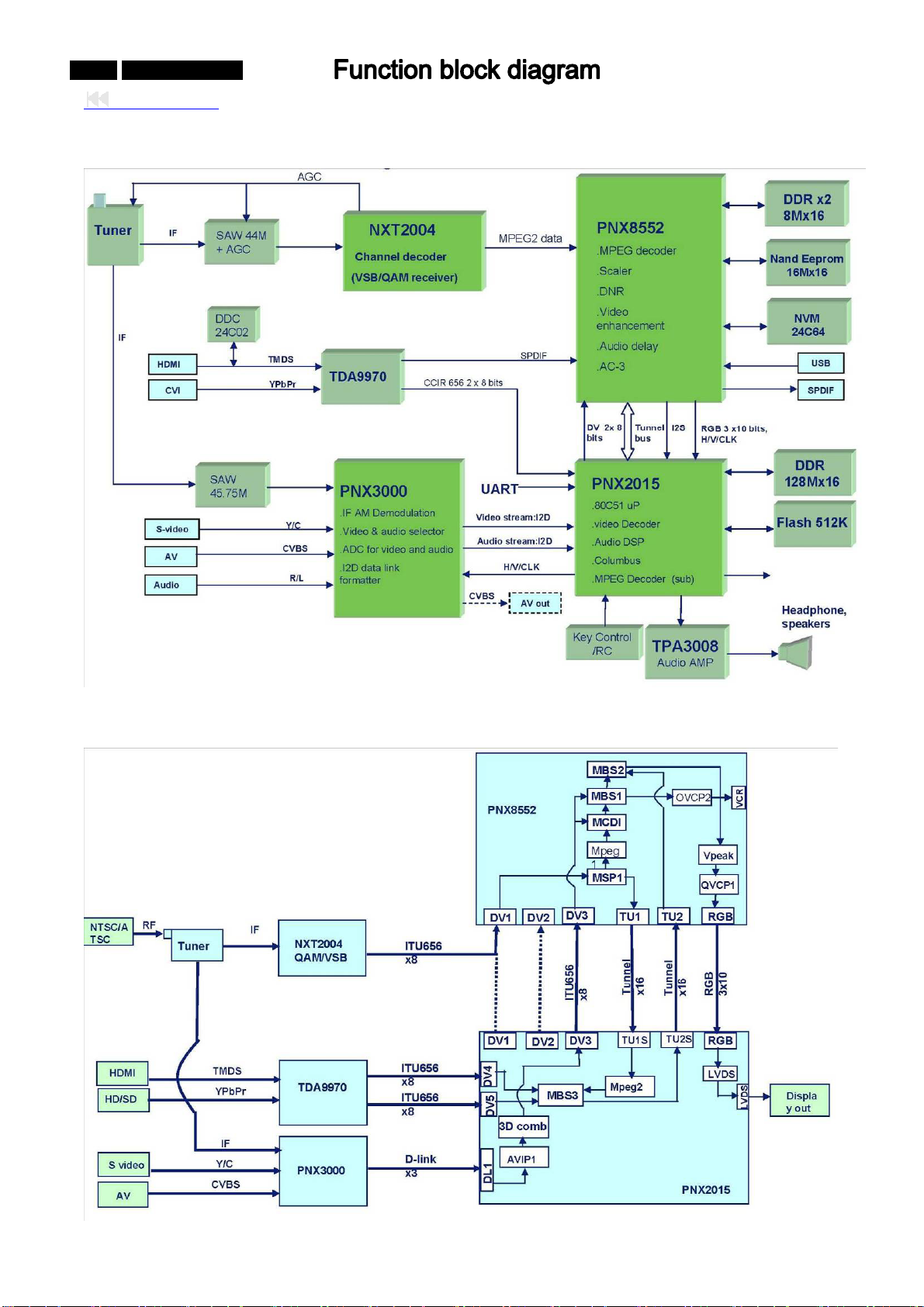
0-57-0 042MF231D/370
Back to cover
Function block
Video Function block
Page 58
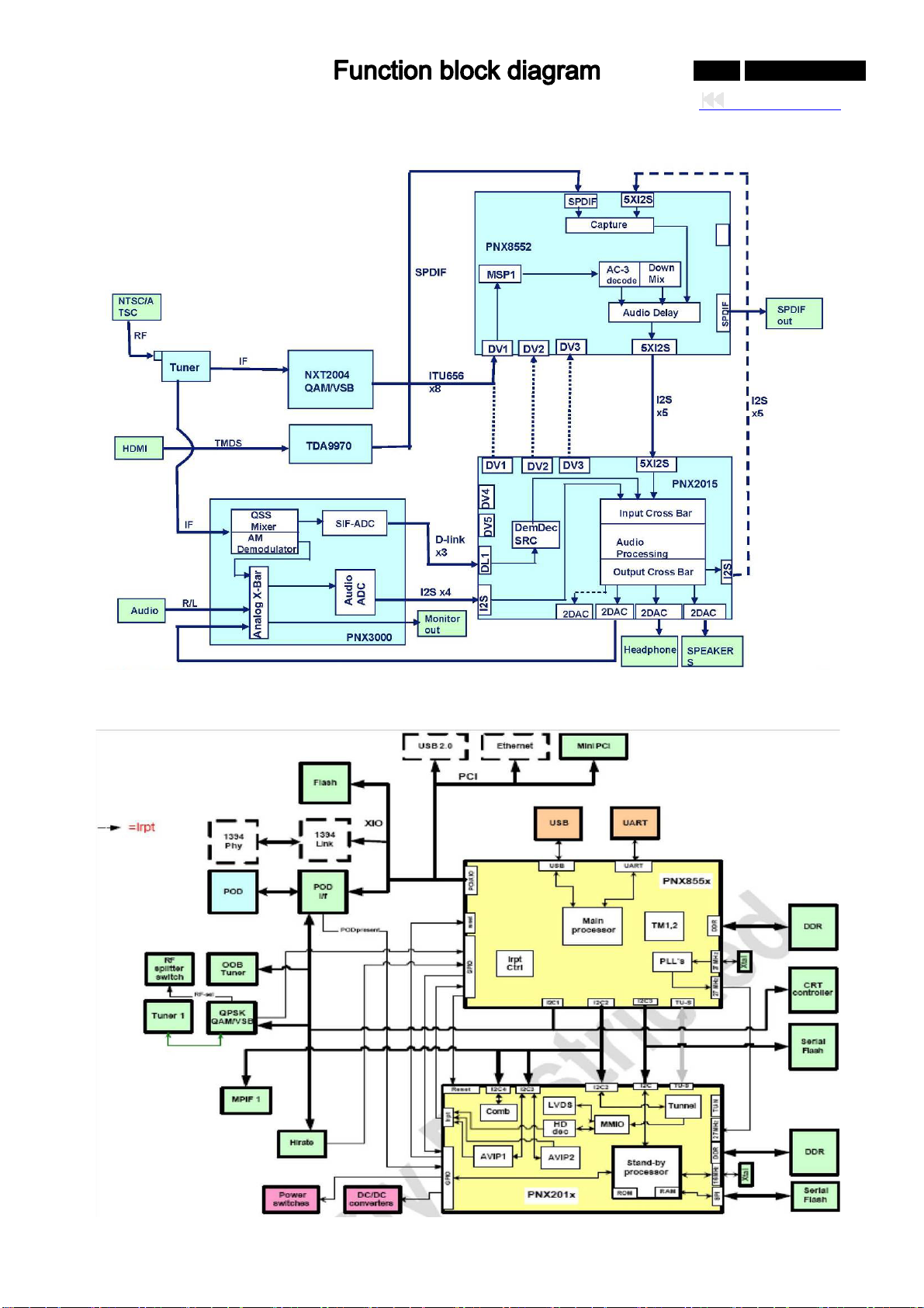
Audio Function block
0-58-0 042MF231D/370
Back to cover
Control Function block
Page 59
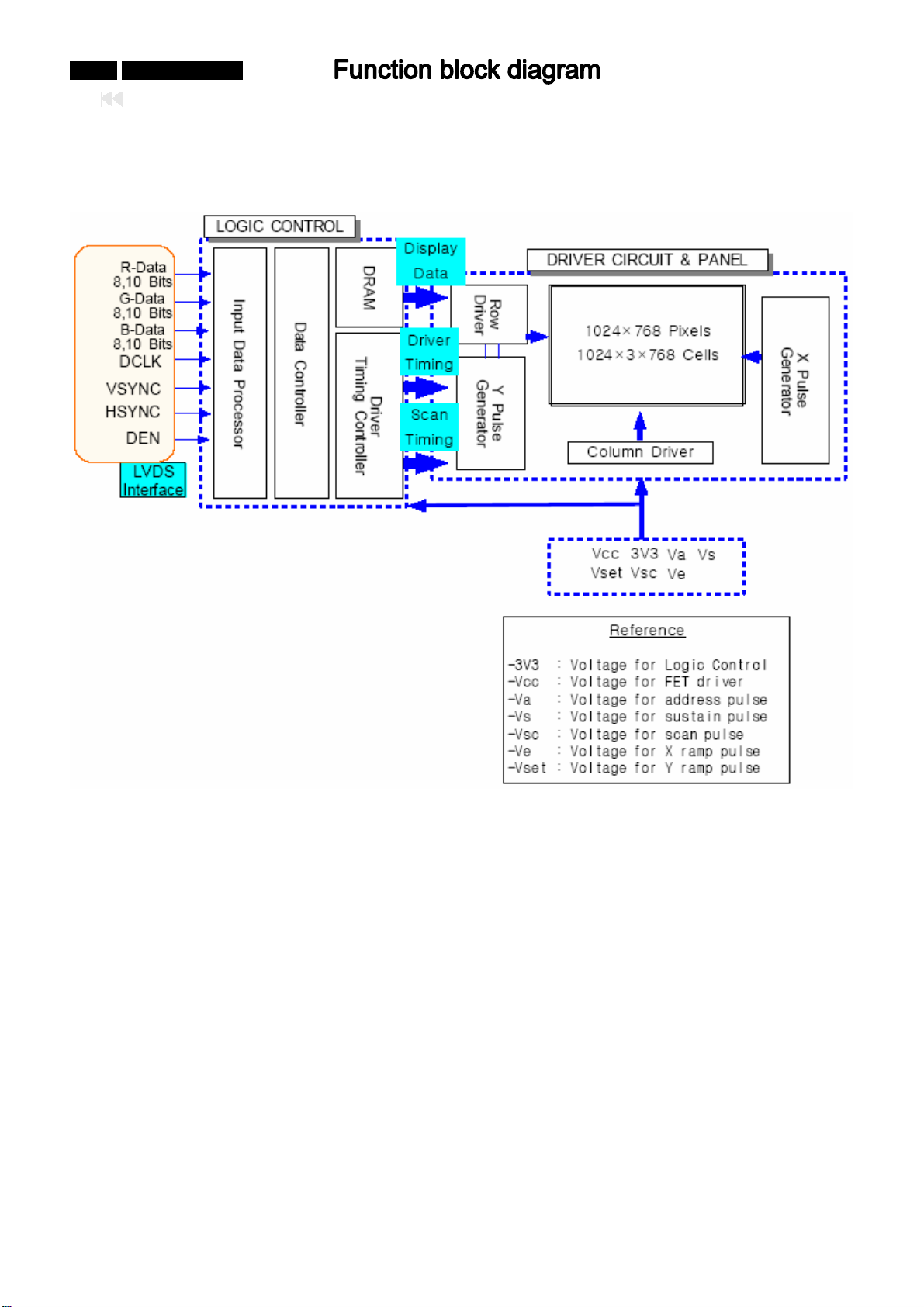
0-59-0 042MF231D/370
Back to cover
Block diagram of PDP PANEL module
Page 60
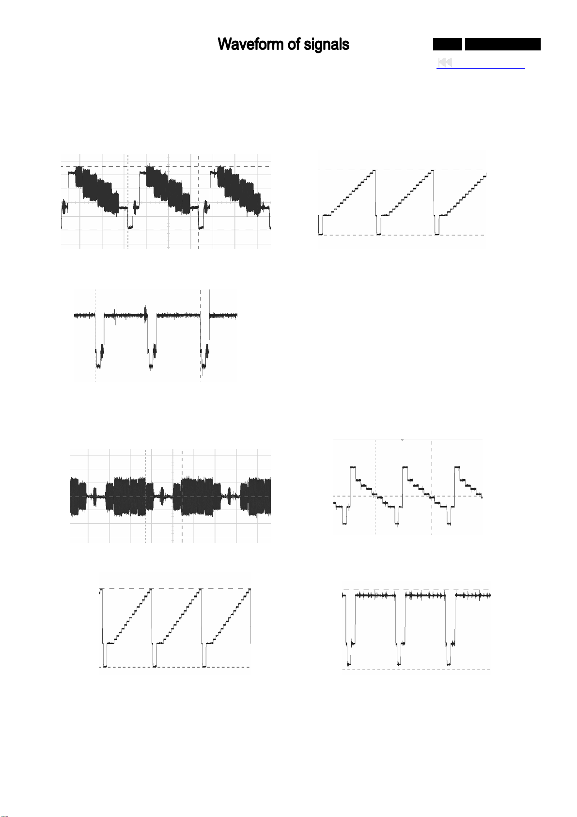
The wave of the video signal form
1. CVBS input
8COLOR BAR OF(CVBS)(II17) 16 GARY STAIR OF(CVBS)(II17)
0-60-0 042MF231D/370
Back to cover
WHITE SCREEN SIGNAL OF(CVBS)(II17)
2. S- VIDEO
8 COLOR BAR OF S-VIDEO(C)SIGNAL(I809) 8 COLOR BAR OFS-VIDEO(Y)SIGNAL(I810)
16 GARY STAIR OF S-VIDEO(Y)SIGNAL(I810) WHITE SCREEN OF S-VIDEO(Y)SIGNAL(I810)
Page 61
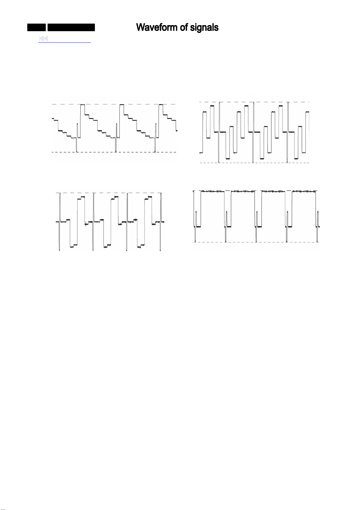
0-61-0 042MF231D/370
Back to cover
3. YPbPr(COM
8 COLOR BAR OF YpbPr(720P)(Y)SIGNAL(I805
PONENT)SIGNAL
) 8 COLOR BAR OF YpbPr(720p)(Pb)SIGNAL(I807)
8 COLOR BAR OF YpbPr(720p)(Pr)SIGNAL(I804) WHITE SCREEN OF YpbPr(720p)(Y)SIGNAL(I805)
Page 62
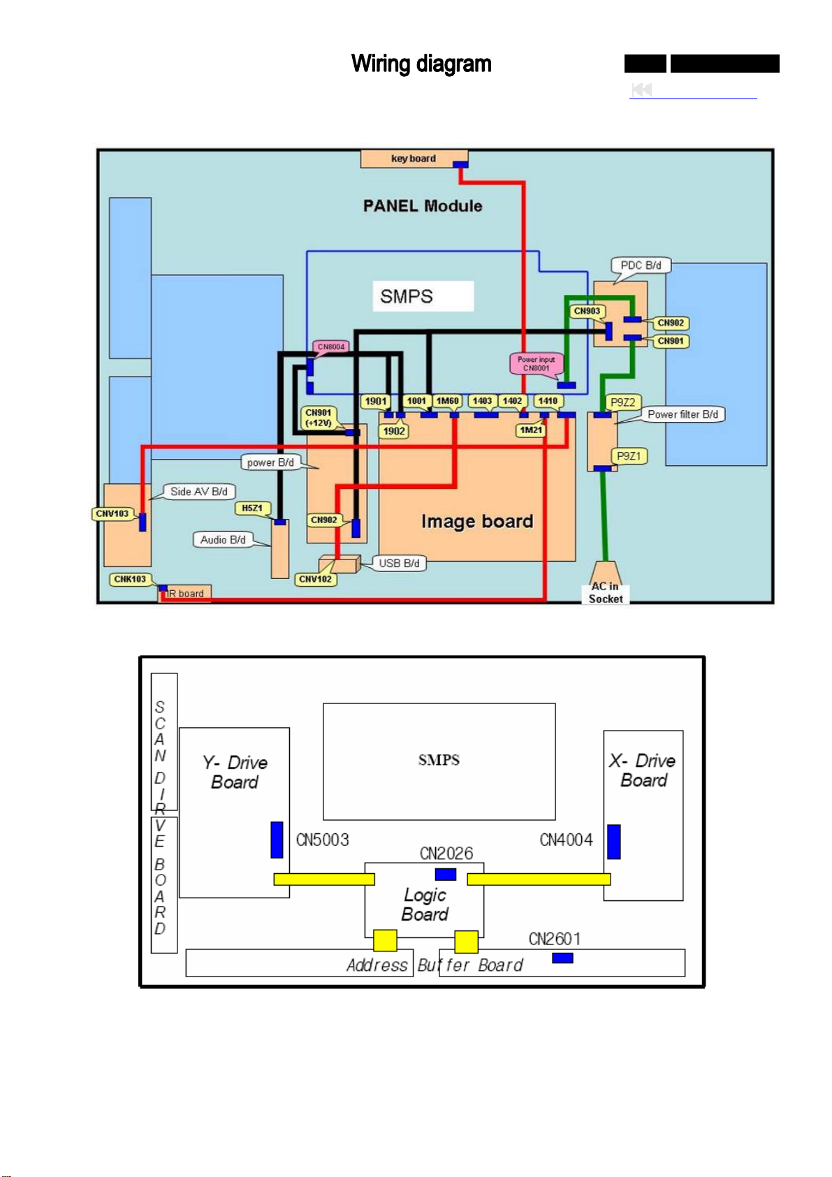
Wiring diagram of PDP
iring diagram of PANEL power input
W
0-62-0 042MF231D/370
Back to cover
1. The Input Power Connector in Y-Drive Board is named as " CN5003".
2. The Input Power Connector in X-Drive Board is named as " CN4004".
3. The Input Power Connector in Logi CN2026".
c Board is named as "
4. The Input Power Connector in Address Buffer Board is named as " CN2601".
Page 63
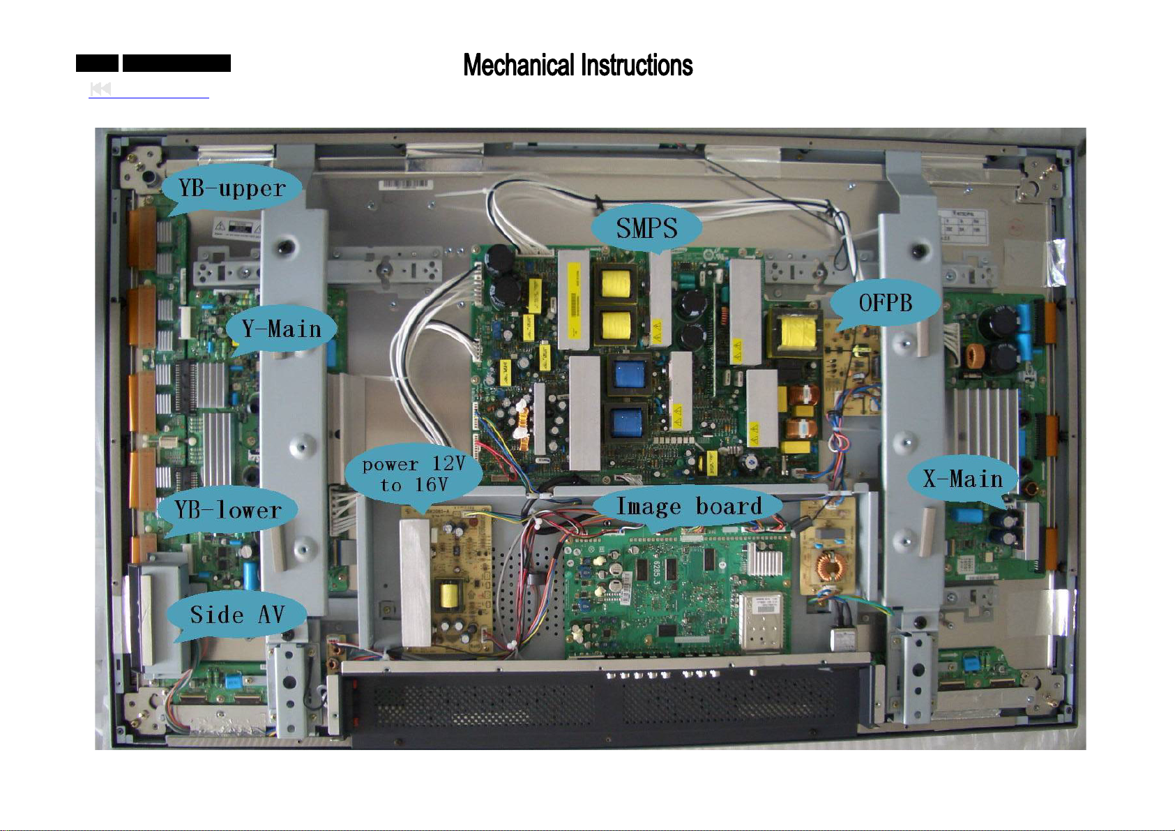
0-63-0 042MF231D/370
0-63-0 042MF231D/370
Back to cover
PDP I nternal view
Page 64
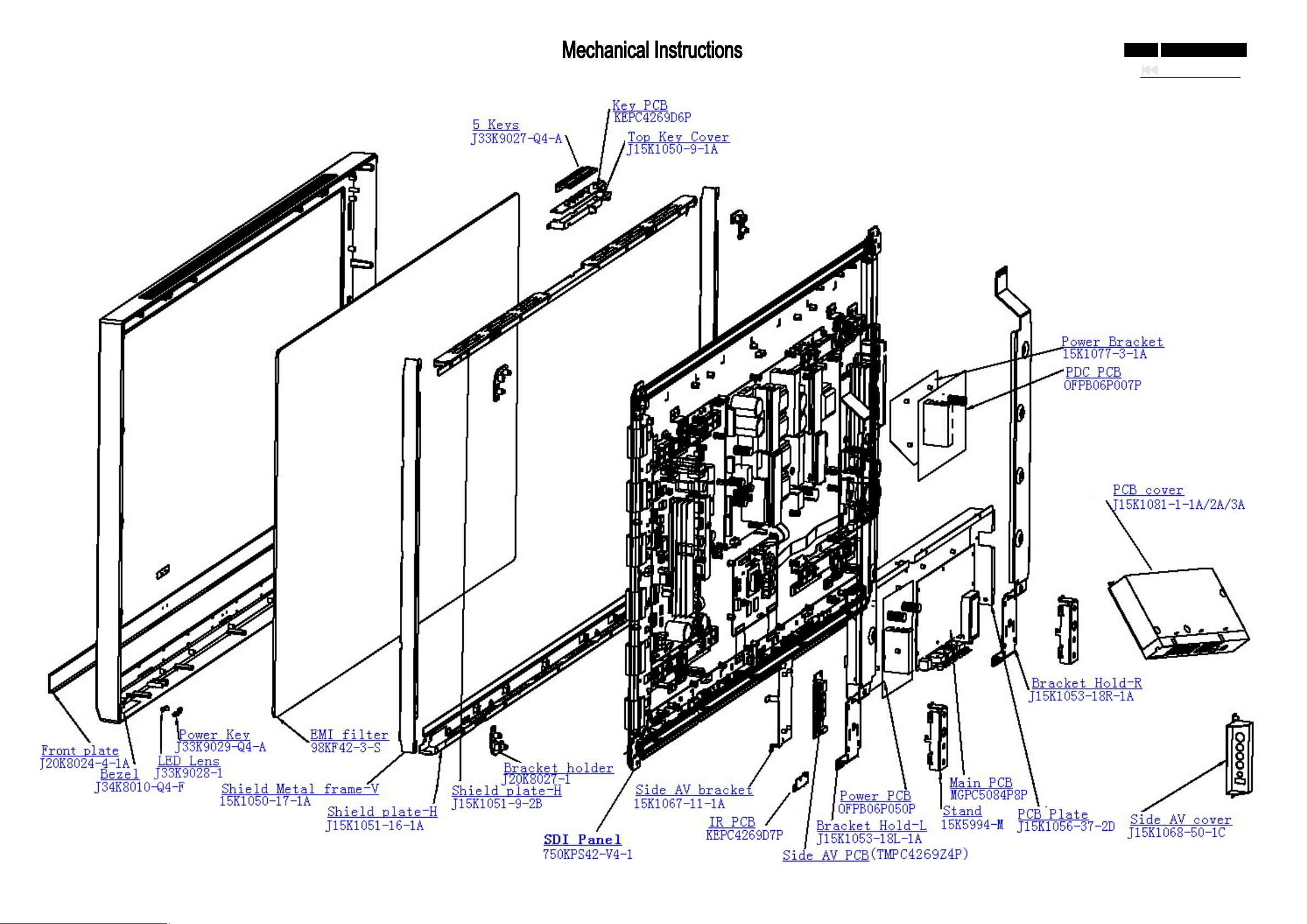
Explode view
0-64-0 042MF231D/370
Back to cover
Page 65
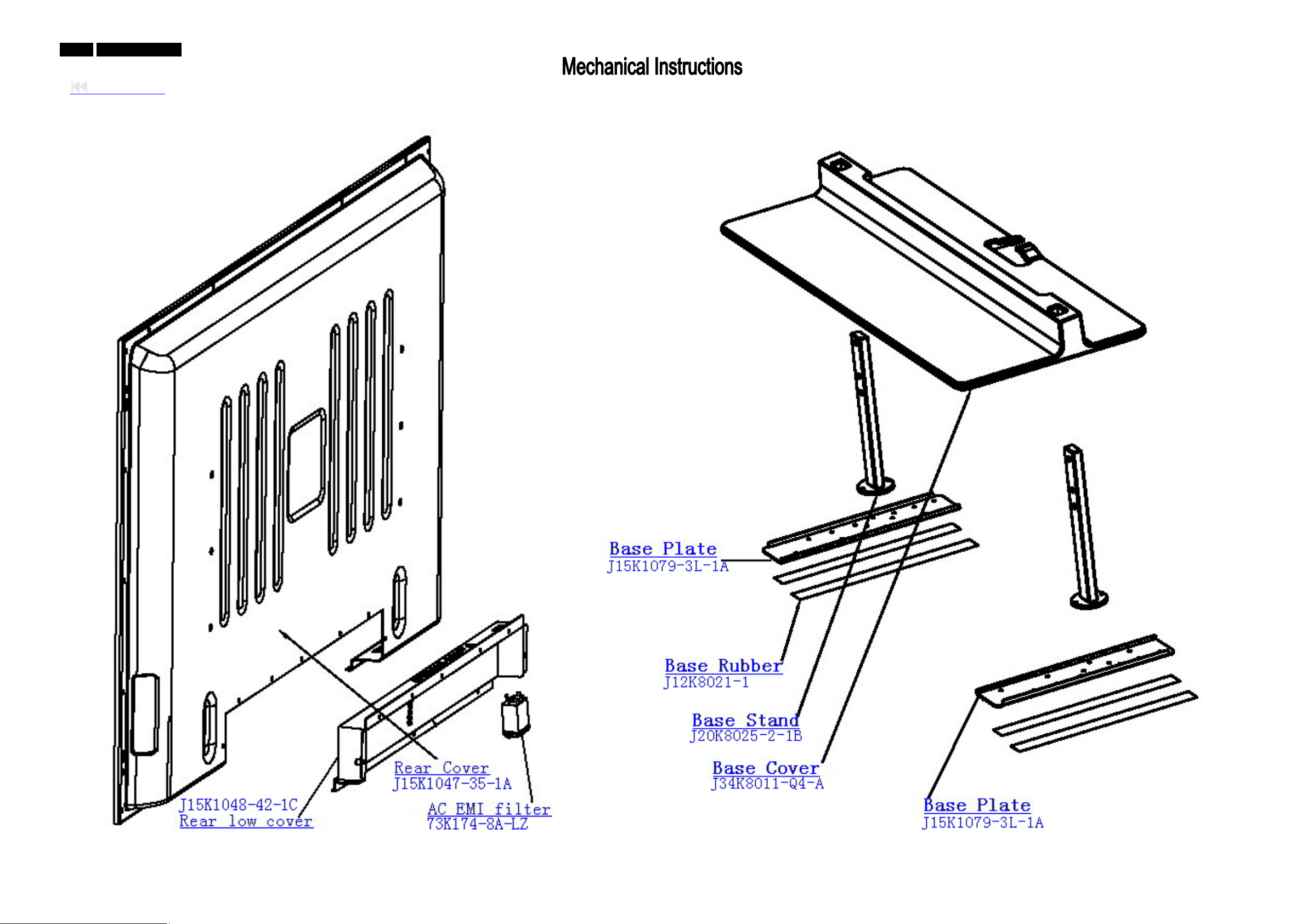
0-65-0 042MF231D/370
Back to cover
Page 66
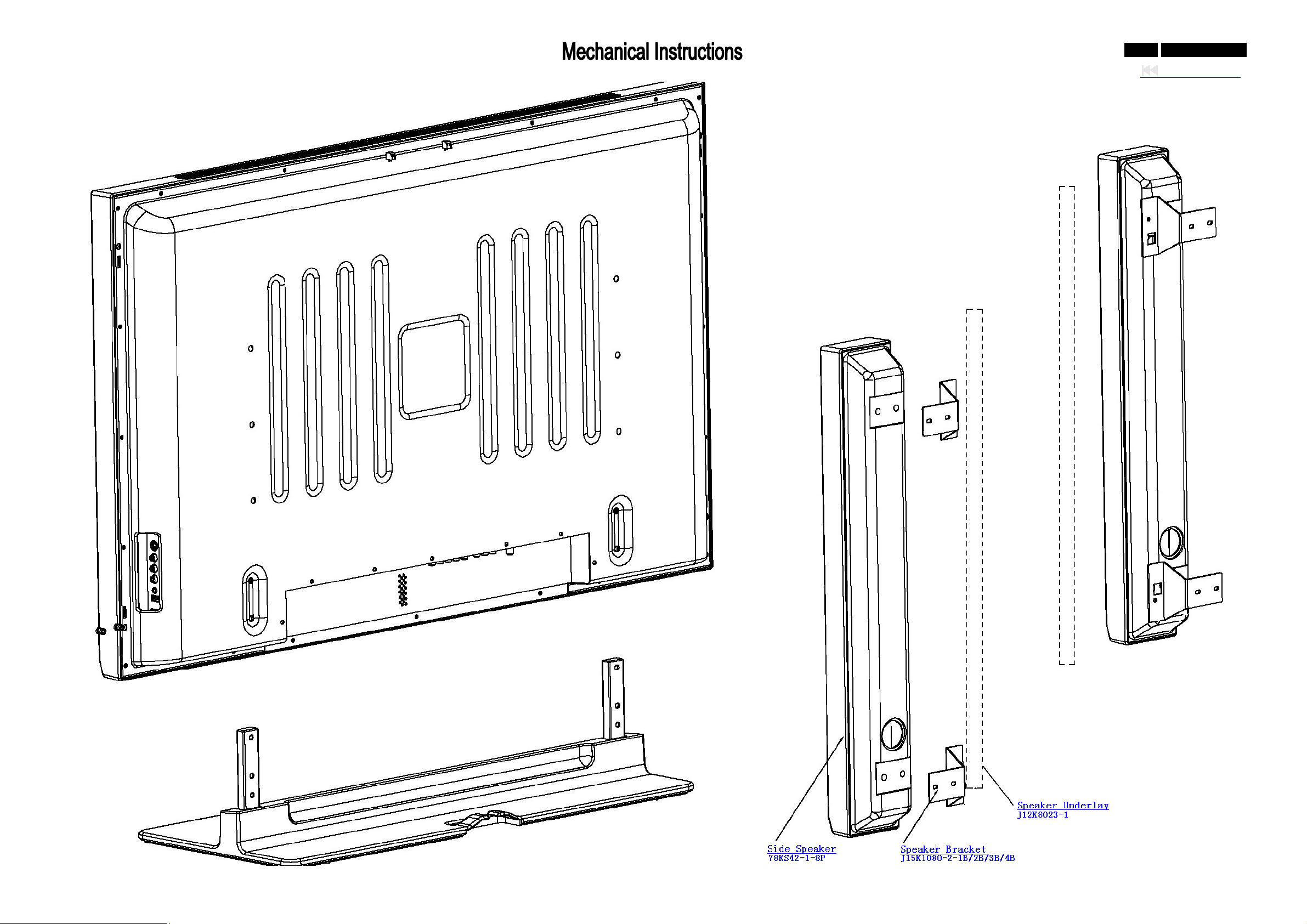
0-66-0 042MF231D/370
Back to cover
Page 67
0-67-0 042MF231D/370
Back to cover
Parts list of explode view
12NC TPV part no. Q’ty Description
Need update J20K8024-4-1A 1 Front Plate
9965 000 39200 J34K8010-Q4-F 1 Bezel
9965 000 39198 J33K9028-1 1 LED Lens
9965 000 39199 J33K9029-Q4-A 1 Power Key
9965 000 34086 98K F42-3-S 1 EMI Conductive Filter
Need update 15K1050-17-1A 2 Shield Metal Frame-V
Need update J15K1051-16-1A 1 Shield Plate-H
Need update J15K1051-9-2B 1 Shield Plate-H
Need update J20K8027-1 4 Bracket Holder
9965 000 39197 J33K9027-Q4-A 1 5 KEY for Top Key
9965 000 39177 715K1973-1 1 KEY PCB
Need update J15K1050-9-1A 1 Top Key Cover
Need update 15K1077-3-1A 1 Power Bracket
9965 000 39180 715K1380-3 1 PDC PCB
9965 000 39175
Need update 15K1067-11-1A 1 Side AV Bracket
9965 000 39178 715K1974-1 1 IR PCB
9965 000 39184 715K1891-1 1 Side AV PCB
Need update J15K1053-18L-1A 1 Bracket Hold-L
9965 000 39181 715K2085-2 1 Power PCB
Need update
9965 000 39179
Need update
Need update
Need update
9965 000 39203 J15K1068-50-1C 1 Side AV Cover
9965 000 39201 J15K1047-35-1A 1 Rear Cover
9965 000 39202
Need update 73K 174-8A-LZ 1 AC EMI Filter
Need update
Need update
Need update
Need update
Need update J15K1079-3R-1A 1 BASE Plate
Need update 78K S42-1-8P 2 Side Speaker
Need update J15K1080-2-1B/2B/3B/4B 1/1/1/1 Bracket Speaker
Need update J12K8023-1 2 Speaker Underlay
PANEL
1
SDI PANEL
15K5994-M 2 Stand Cover
715K3138-158-662-7103
J15K1056-37-2D
J15K1053-18R-1A
1
1 PCB Plate
1 Bracket Hold-R
Main board PCB
J15K1081-1-1A /2A/3A 1/1/1 PCB Cover
J15K1048-42-1C 1 Rear Low Cover
J15K1079-3L-1A 1 BASE Plate
J12k8021-1 4 BASE Rubber
J20K8025-2-1B 2 BASE Stand
J34K8011-Q4-A 1 BASE Cover
Page 68
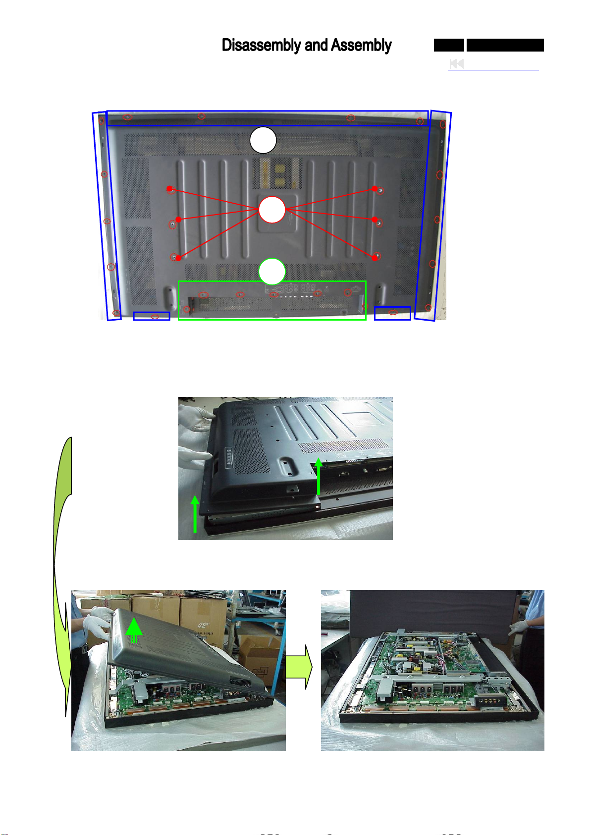
0-68-0 042M F231D/370
Back to cover
Back Cover Removal
1) Remove the six big black colored screws in the panel holder as the red-circle showed (1).
2) Remove the seven black colored screws around the terminals as the green-pane showed (2).
3) Remove the Sixteen black colored screws around the back cover as the blue-pane showed (3).
4) Carefully prize up the back cover from the left of the PDP (5).
5) Carefully remove the Back Cover from the top
of the PDP, and store in a safe place.
3
1
2
6) Done.
Page 69
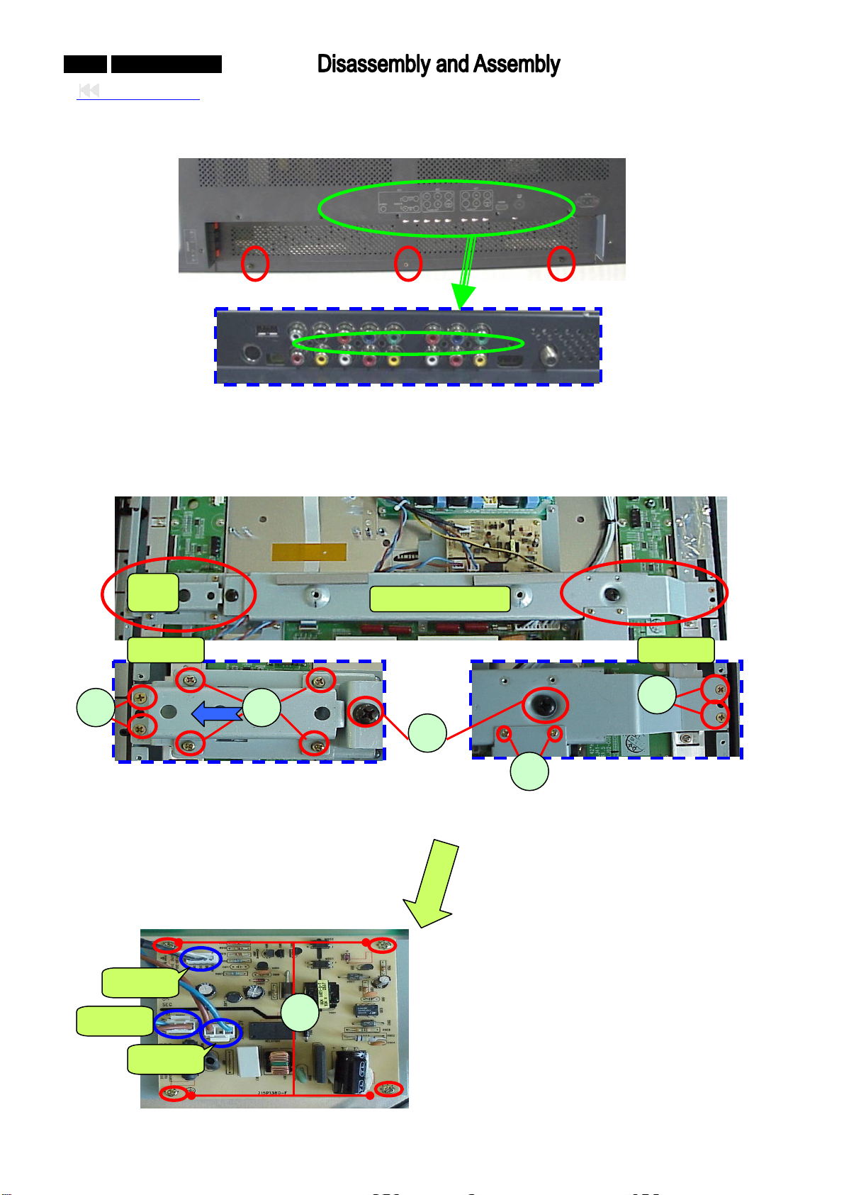
0-69-0 042MF231D/370
Back to cover
ear Low Cover removal
R
PDC Board (pow control) R
1) Remove the thre ear low cove
2) Remove the lack screws .
six b
er down emoval
Pa
sta
nel
nd
ZOOM 1
1) R er s ve the pane tand r as the
emove the four sliv crews (1) and remo l s from panel holde
d howe
irection arrowed s d.
2) Remov ilver fla
3) Remov ack sc
4) Re ilver sc
5) Re l holde
e the four s t screws (2).
e the two bl
move the two s
move the pane r from PDP.
CN903
CN901
CN
902
e black screws in R r.
Panel Holder
rews (3)
rews (4)
6) Disconnect CN90 N903 from PDC
.
board
7) Remove th ur s d remove the
PDC board.
e fo liver screws (5), an
ZOOM 2
1,CN902 and C
Page 70
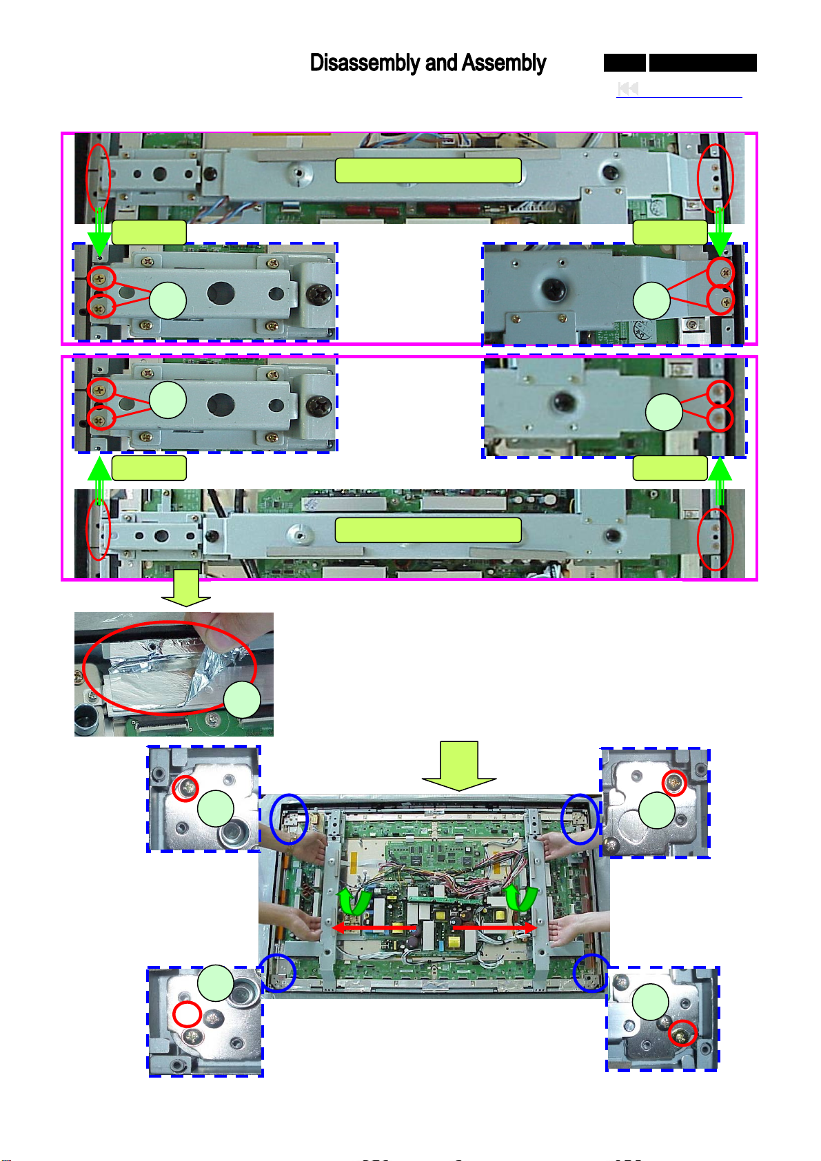
P Module Removal
anel
ZOOM 1 ZOOM 2
Panel Holder-1
0-70-0 042MF231D/370
Back to cover
ZOOM 3 ZOOM 4
Panel Holder-2
1) Remove the eight silver flat screws around the two panel holder (1).
2) Remove all the aluminum foil around the panel (2), after assemble
the new panel, must re-affix the aluminum foil, if it’s broken must
change a new one, otherwise, the EMI can be affected.
3) Remove the four silver screw around the PANEL corner (3).
4) Two people hold the panel holder 1 and 2 respectively, then uplift the
panel module and move it out form the front cover(Bezel), and store
in a safe place.
Page 71
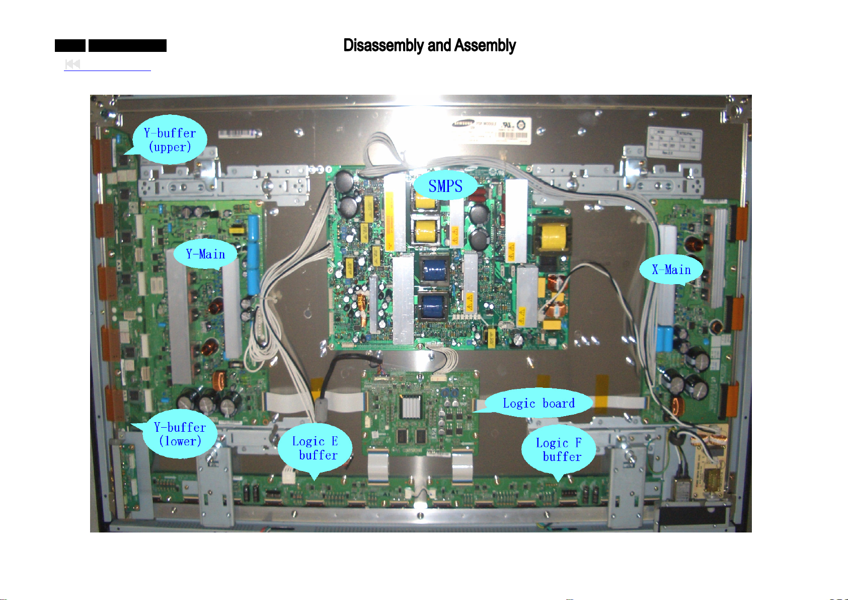
-71-0 042MF231D/370
0
Back to cover
PANEL Intern iew
al v
Page 72
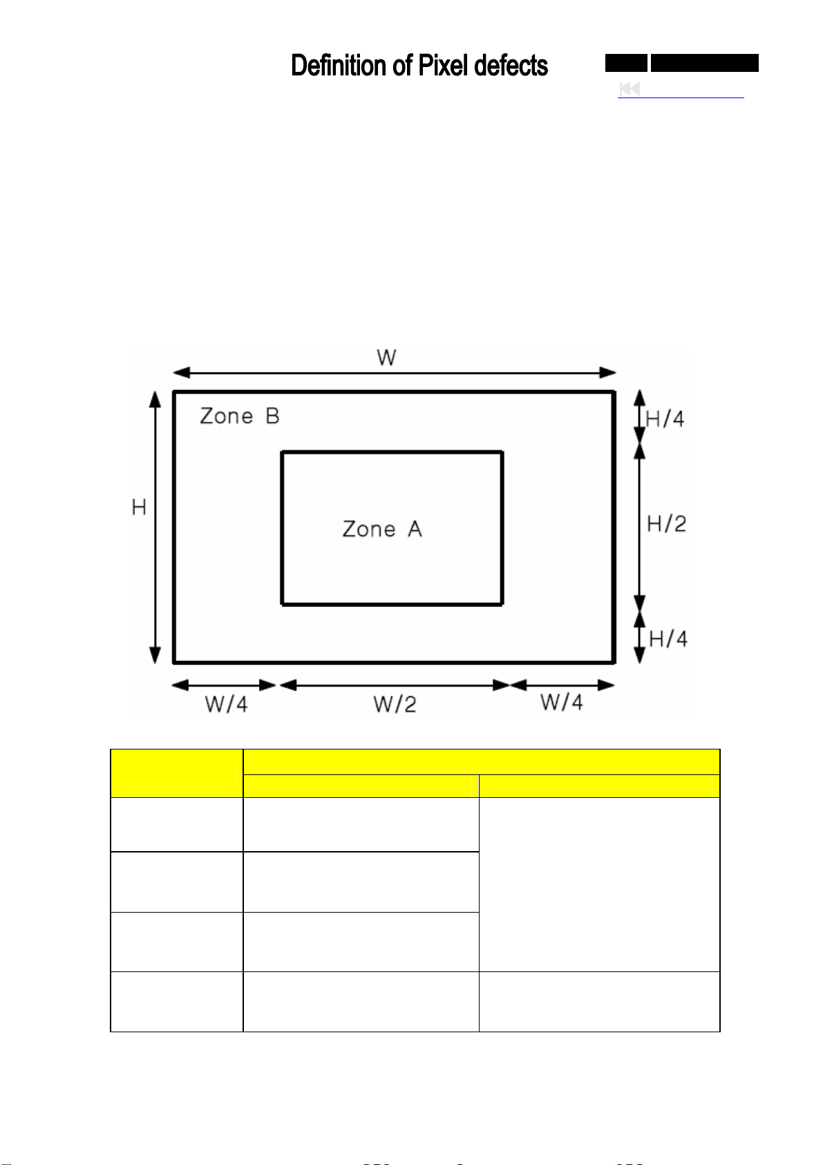
0-72-0 042MF231D/370
Back to cover
Cell Defect of PANEL
A panel may have defective cells that cannot be controlled. These defective cells can be categorized
into three types;
(1) Non-lighting cell defect: defect in which the cell is always off
(2) Non-extinguishing cell defect: defect in which the cell is always on.
(3 g cell defect: defect in which the cell is flickering.
) Flickerin
(4) Test Pattern: Full White, Full Red, Full Green and Full Blue with 1023(10Bit) gray level.
The display efect specifications define the allowed limits for display cell defects a are used as
cell d nd
the criteria in determining whether a panel should be allowed.
Item
Non-lighting
cell defect
Non-extinguishing
cell defect
Flickering
cell defect
Total Defect
Number of cell defects Distance between cell defects
Zone A: 3 and less
Zone B: 8 and less
Zone A: 0
Zone B: 1 and less
Zone A: 0
Zone B: 1 and less
Total number of cell defects in
Zone A and B is 8 and less
Specification
Regardless of A and B zone,
-Distance between the cells is over
15mm
Page 73
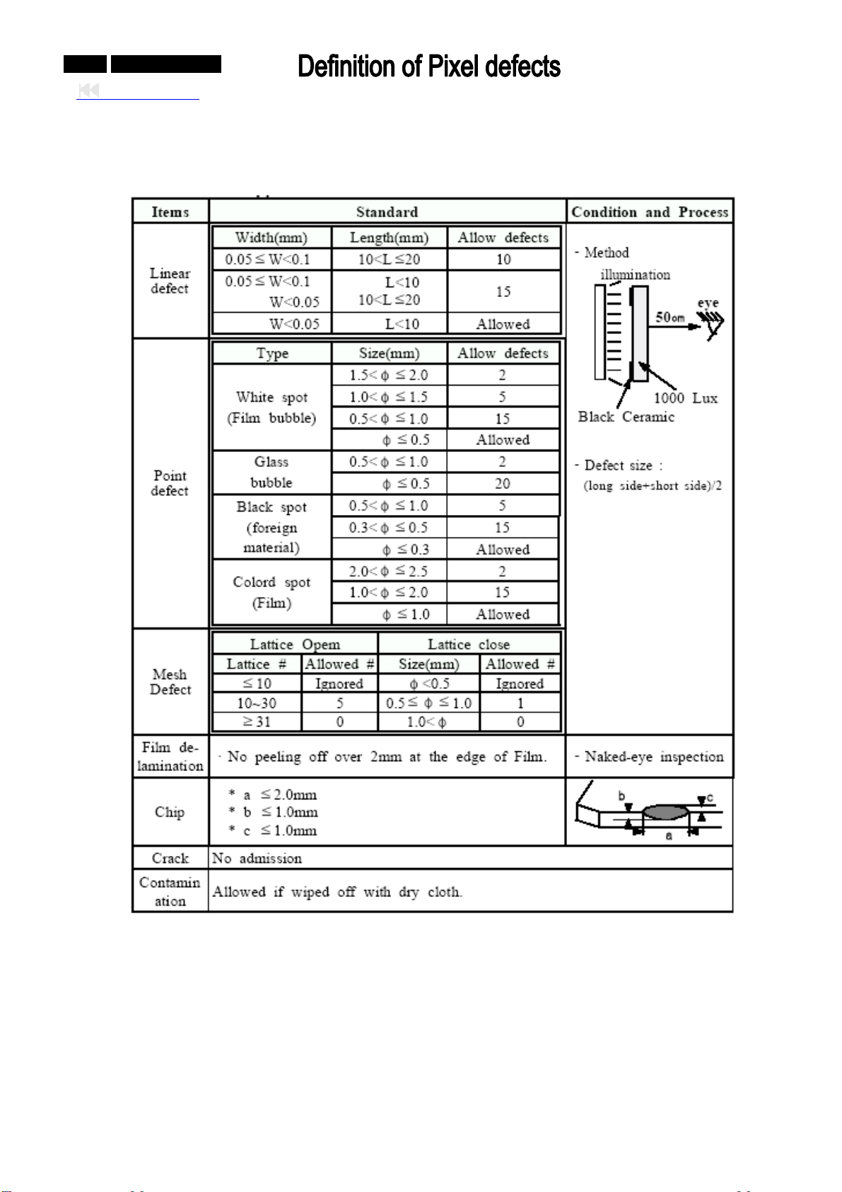
0-73-0 042MF231D/370
Back to cover
Defects of Glass filter
z But, the distance between defects must be over 30mm.
Any defect without prescribed contents on the specifications shall be settled on deliberation by
z
both parties.
Page 74

Page 75
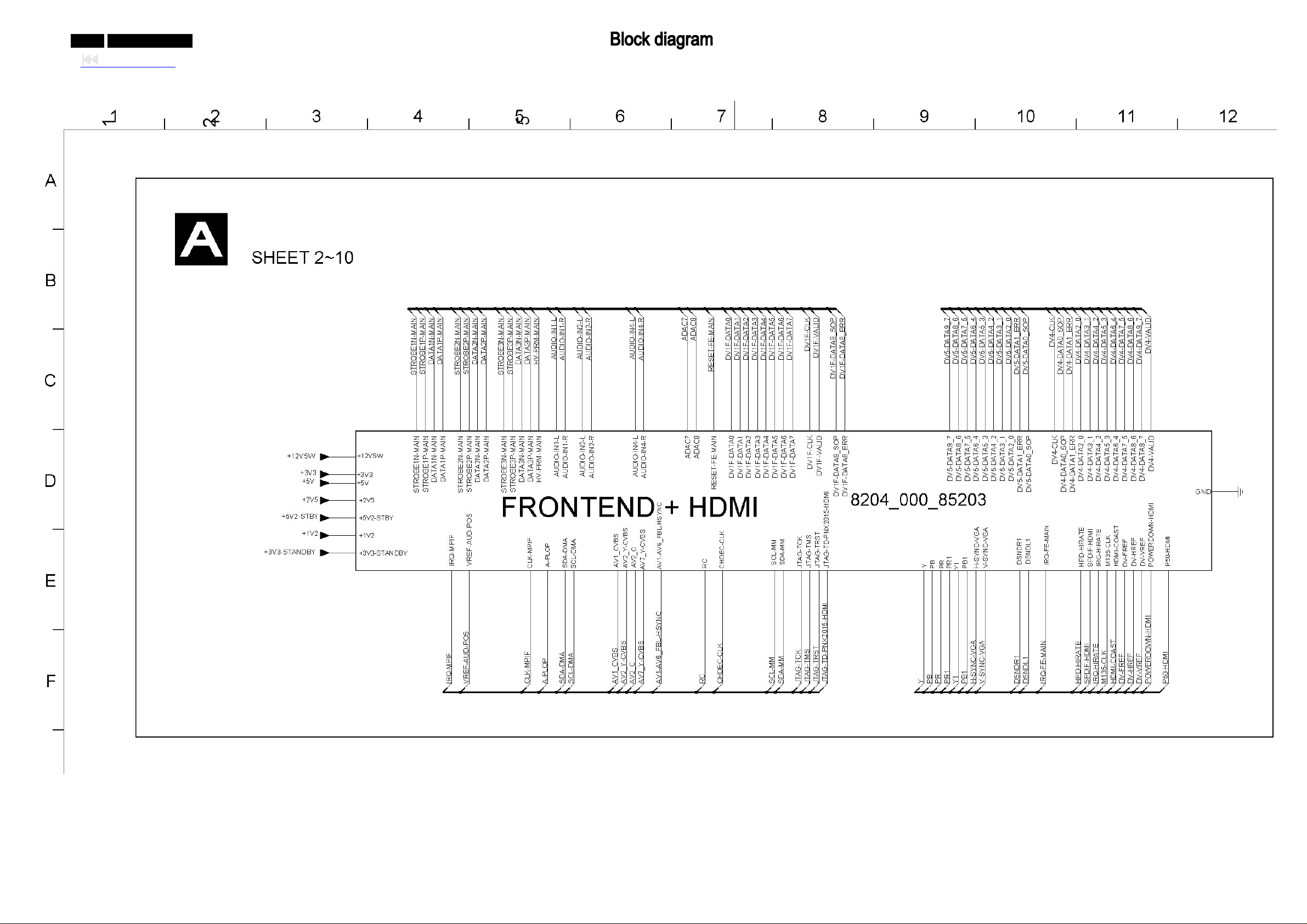
0-75-0 042MF231D/370
Back to cover
Page 76
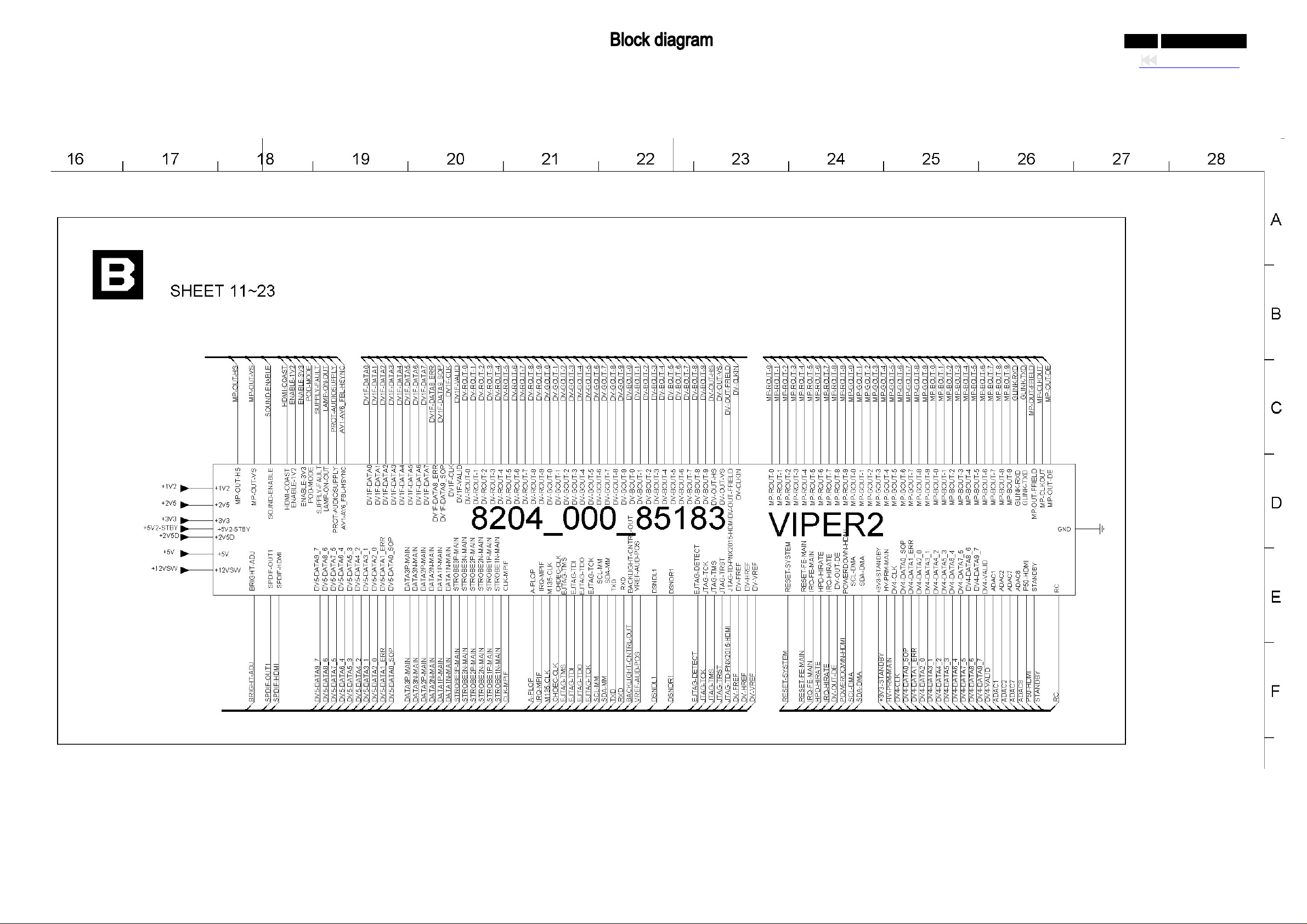
0-76-0 042MF231D/370
Back to cover
Page 77
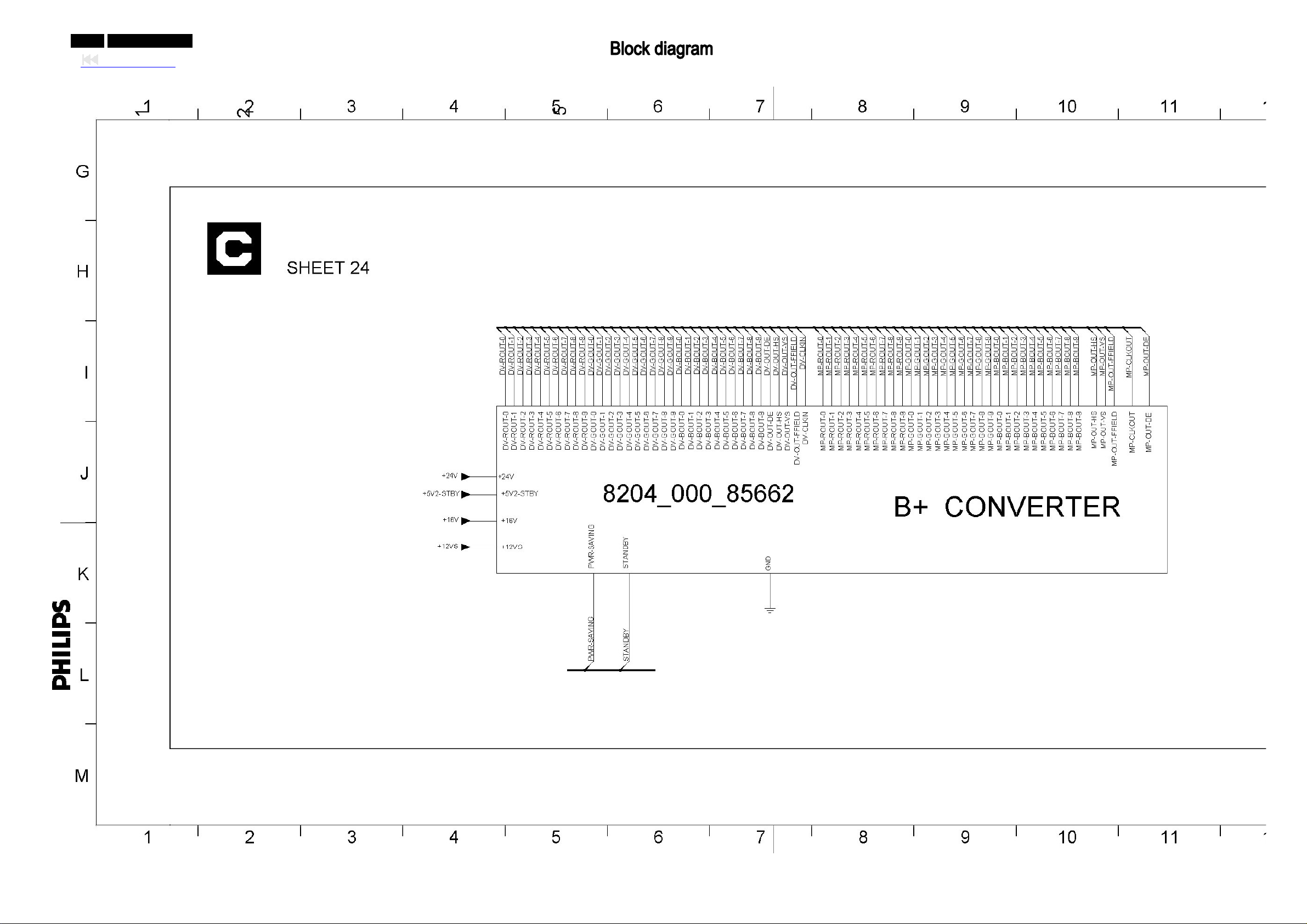
0-77-0 042MF231D/370
Back to cover
Page 78
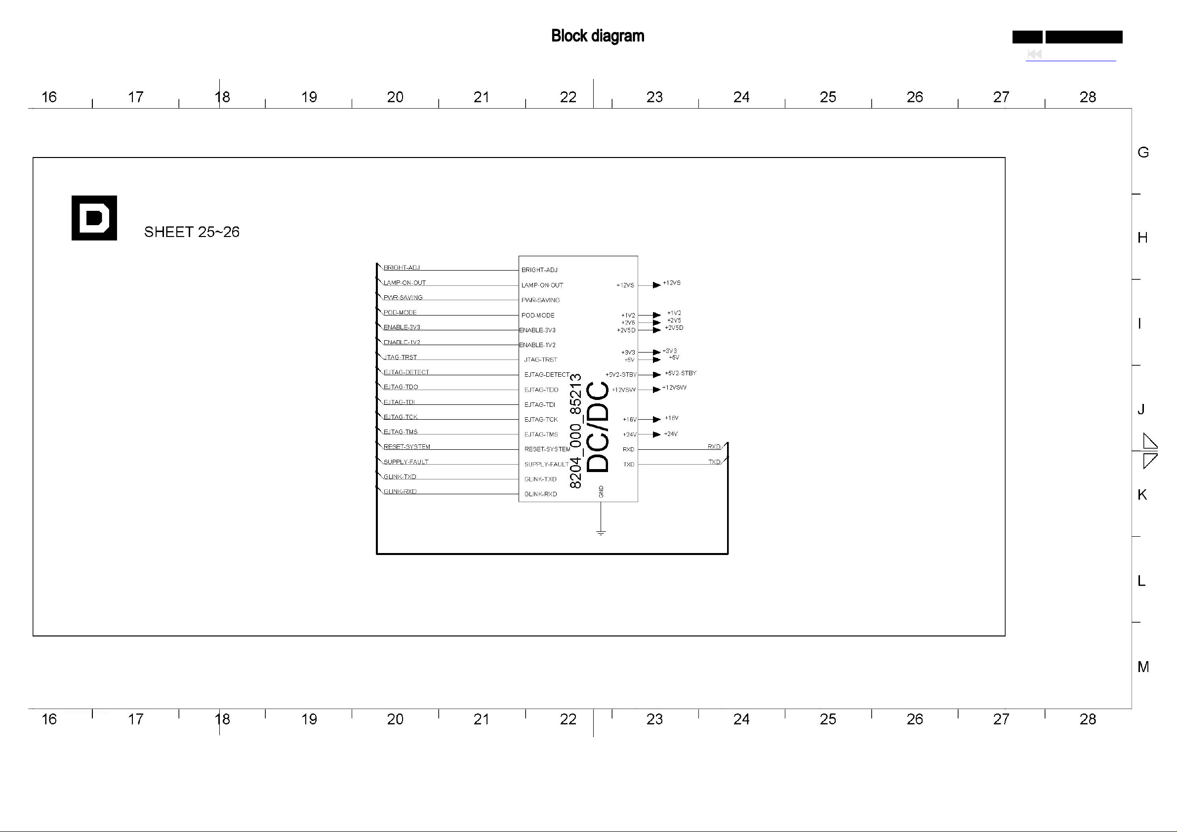
0-78-0 042MF231D/370
Back to cover
Page 79
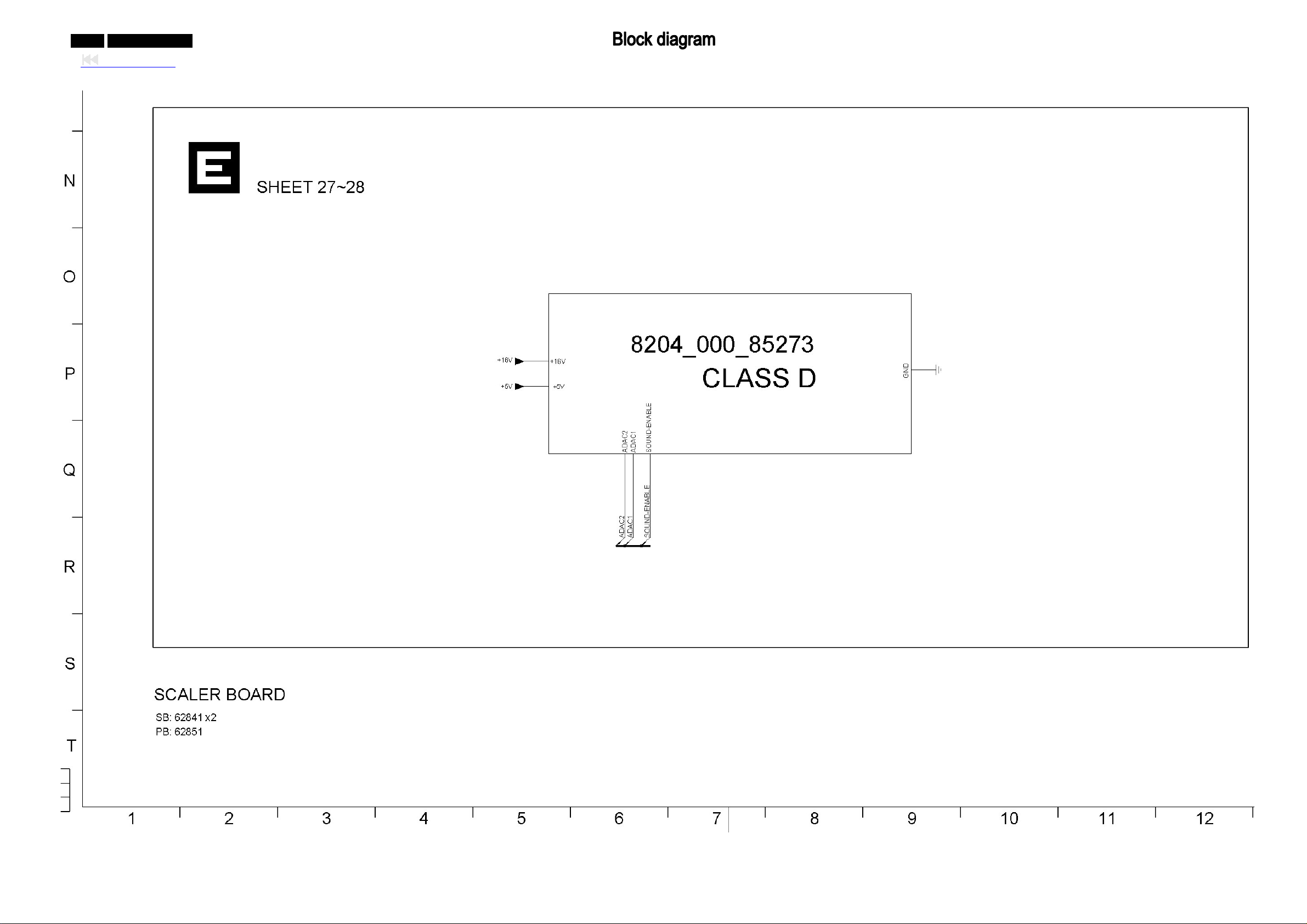
0-79-0 042MF231D/370
Back to cover
Page 80
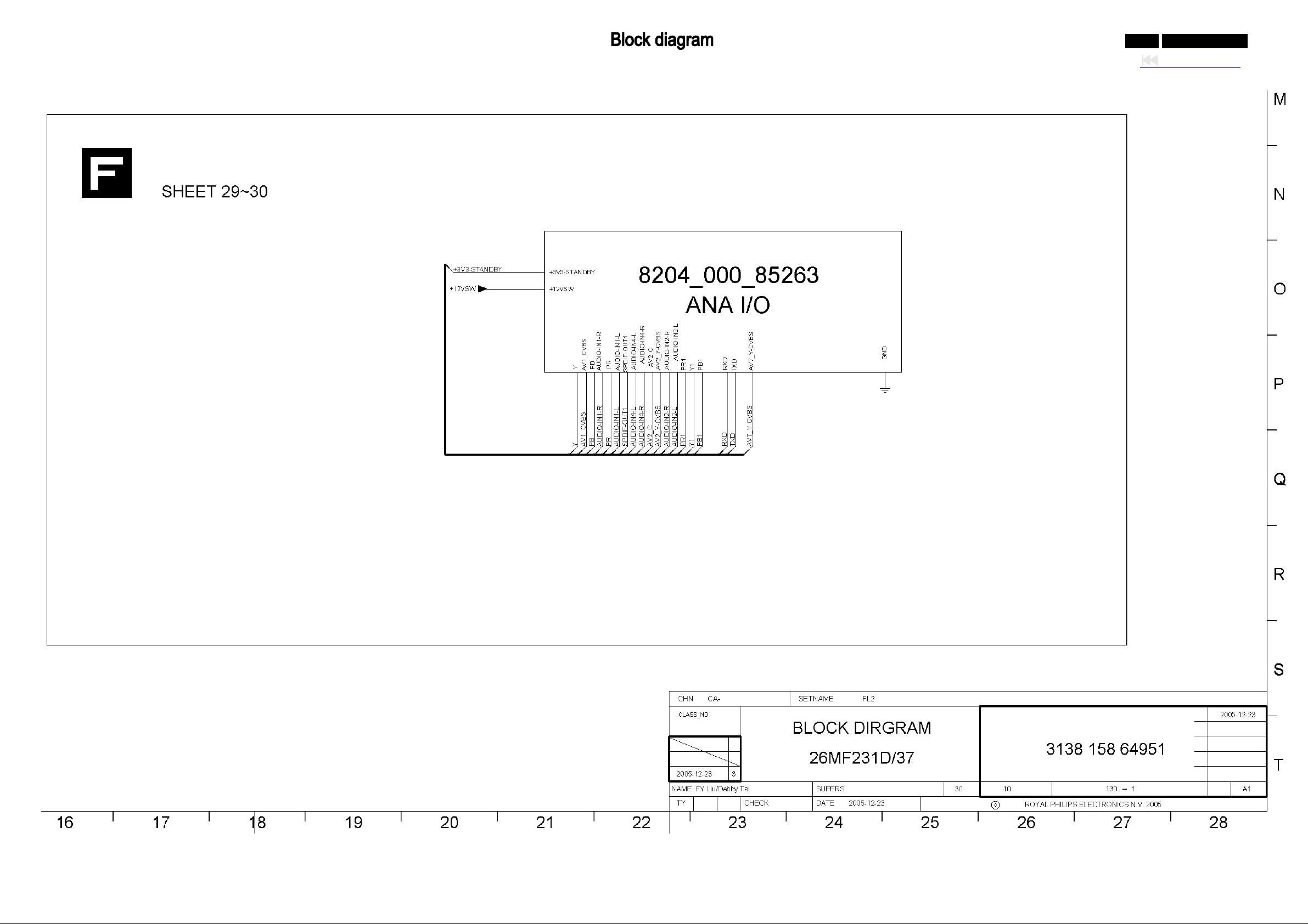
0-80-0 042MF231D/370
Back to cover
Page 81

0-81-0 042MF231D/370
Back to cover
Page 82
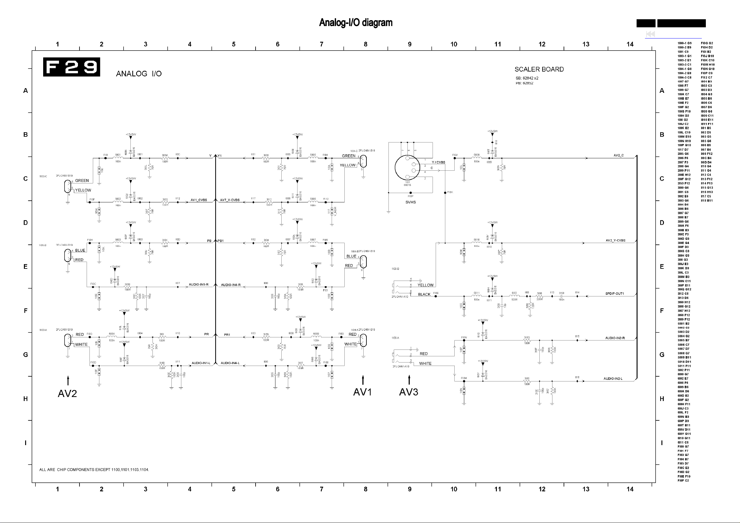
0-82-0 042MF231D/370
Back to cover
Page 83
0-83-0 042MF231D/370
Back to cover
Page 84
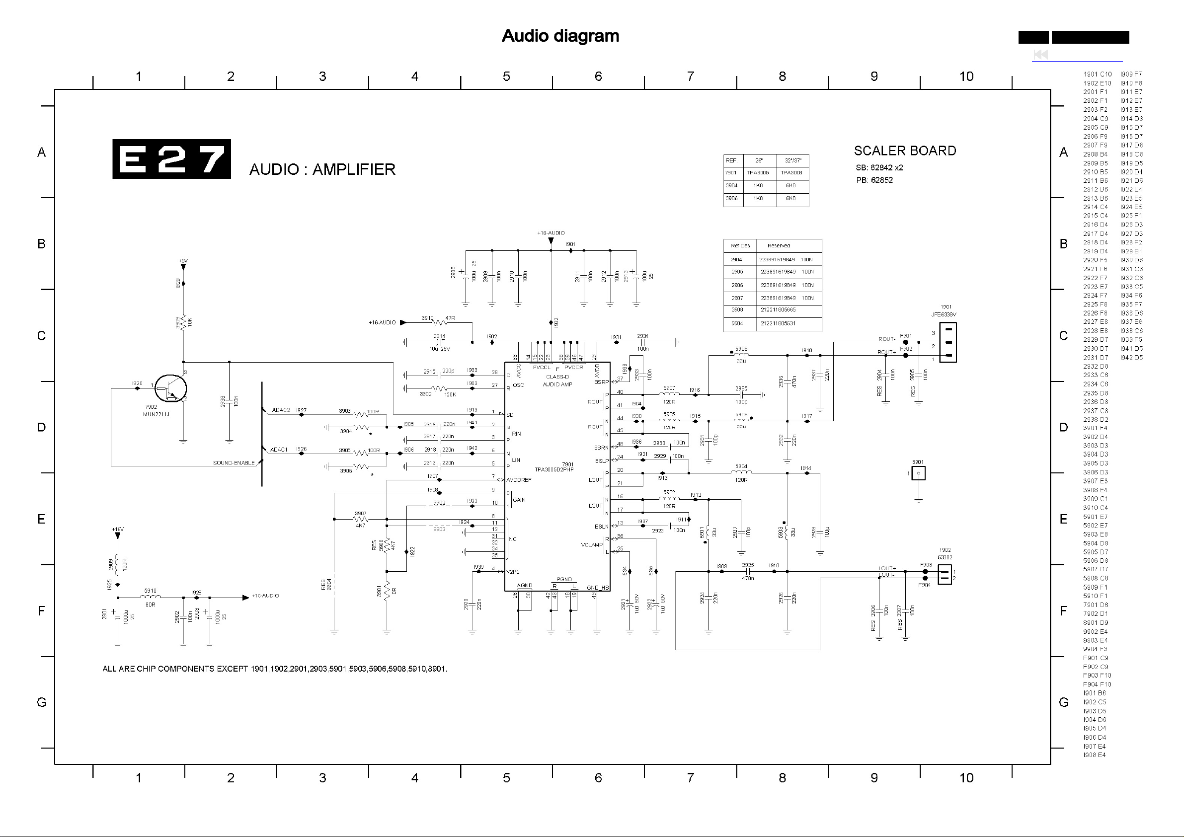
0-84-0 042MF231D/370
Back to cover
Page 85
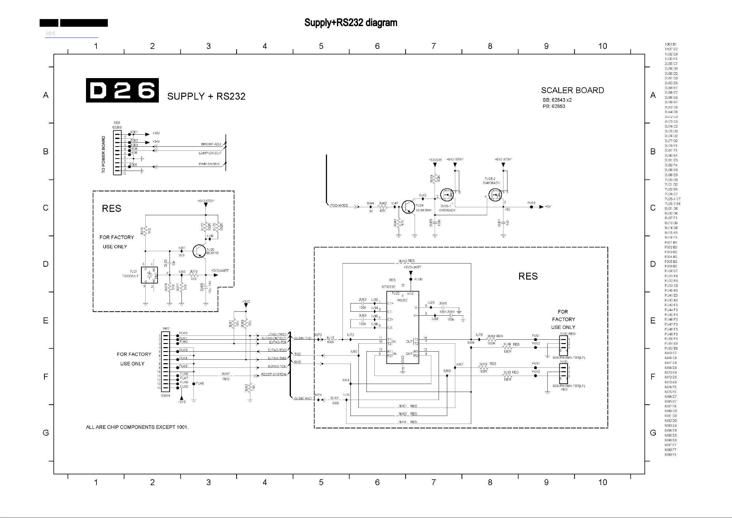
0-85-0 042MF231D/370
Back to cover
Page 86
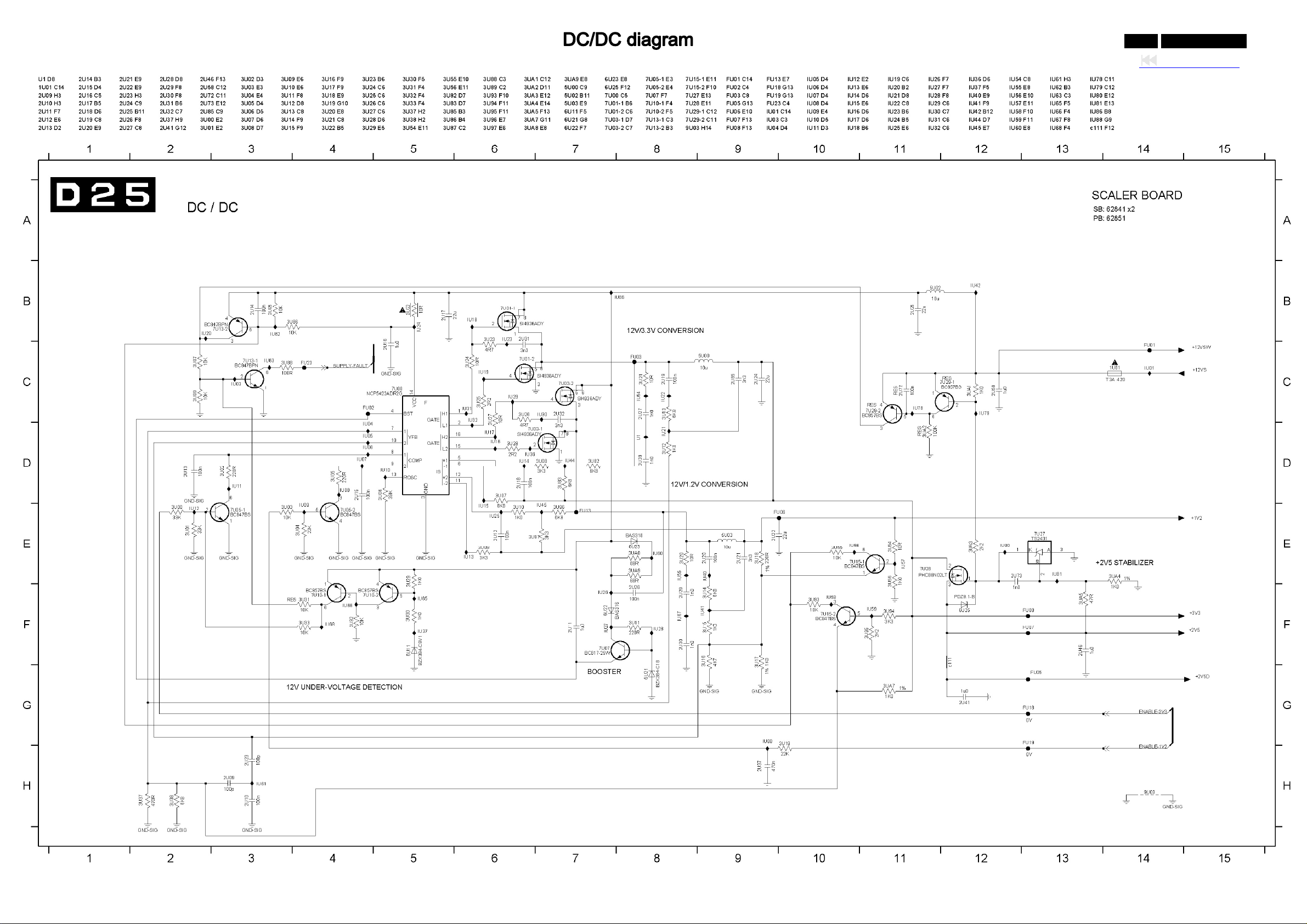
0-86-0 042MF231D/370
Back to cover
Page 87
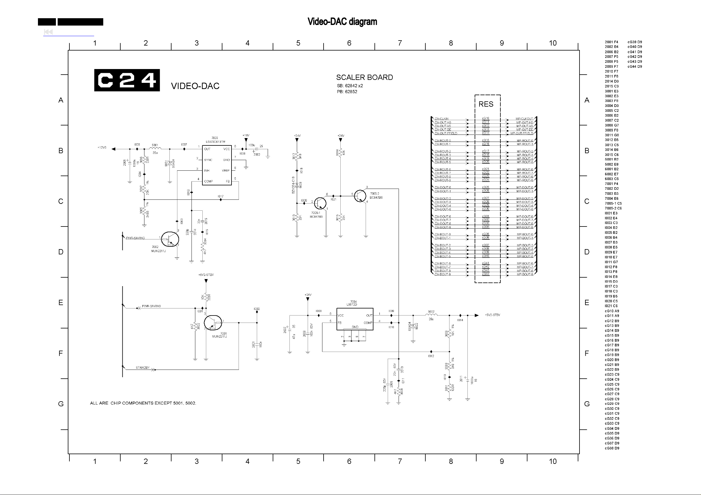
0-87-0 042MF231D/370
Back to cover
Page 88
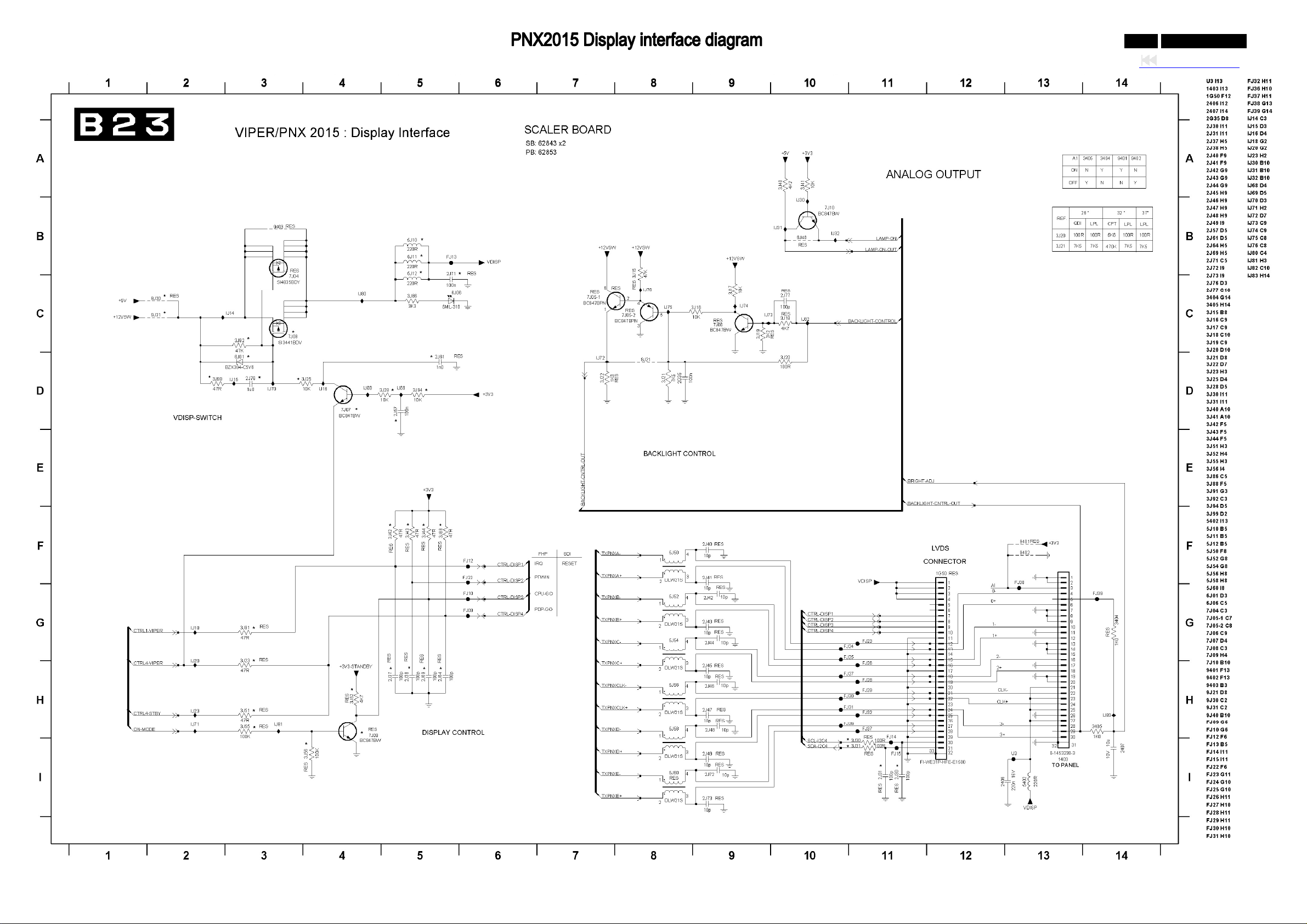
0-88-0 042MF231D/370
Back to cover
Page 89
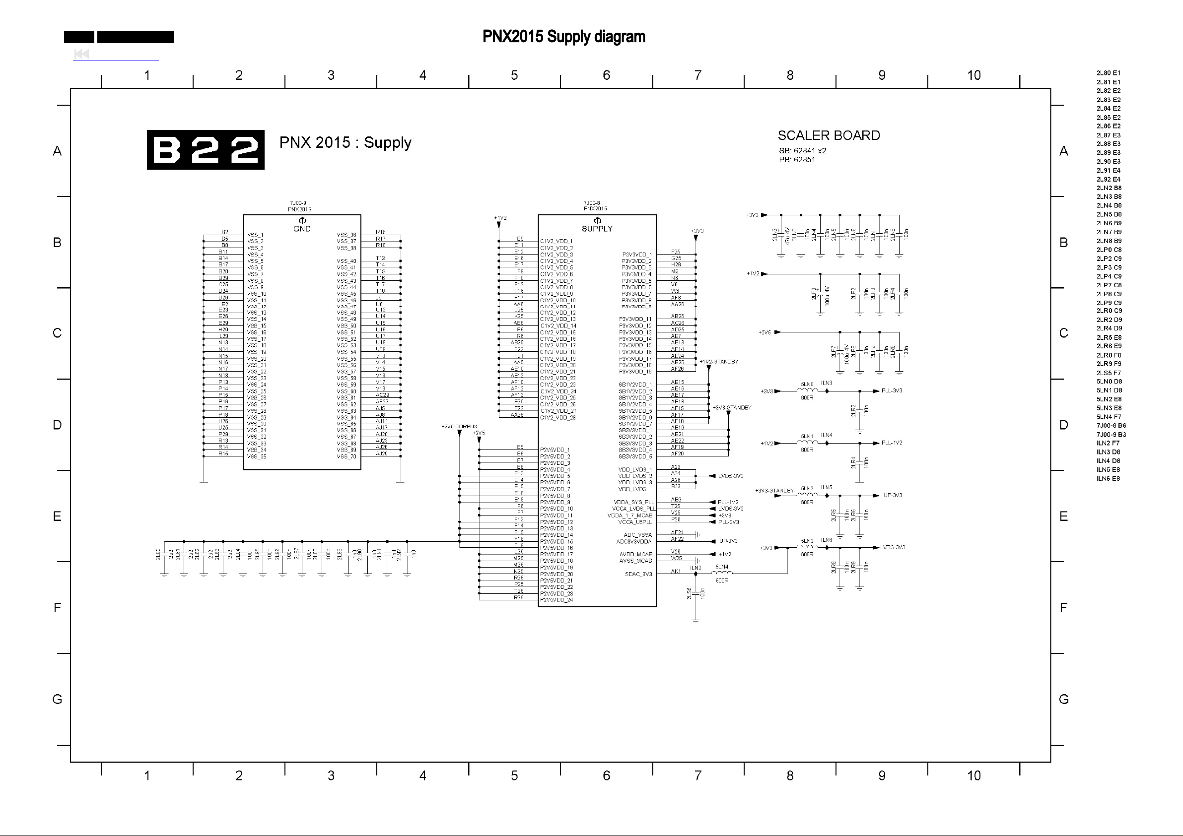
0-89-0 042MF231D/370
Back to cover
Page 90
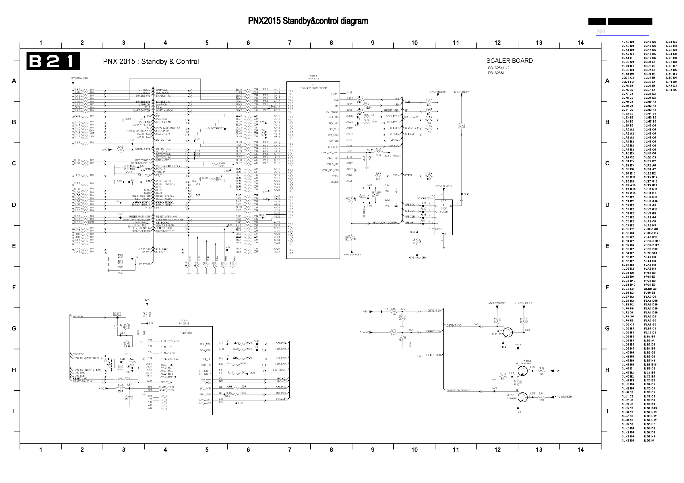
0-90-0 042MF231D/370
Back to cover
Page 91
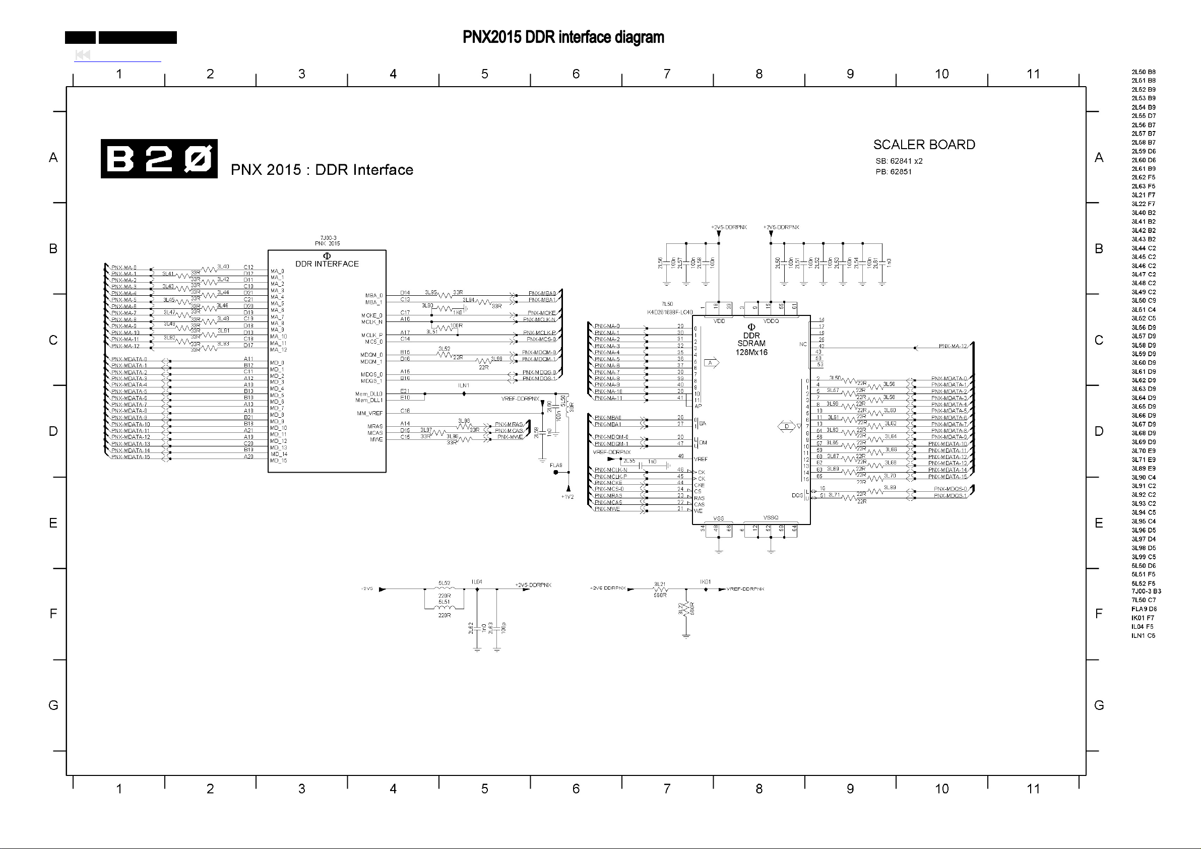
0-91-0 042MF231D/370
Back to cover
Page 92
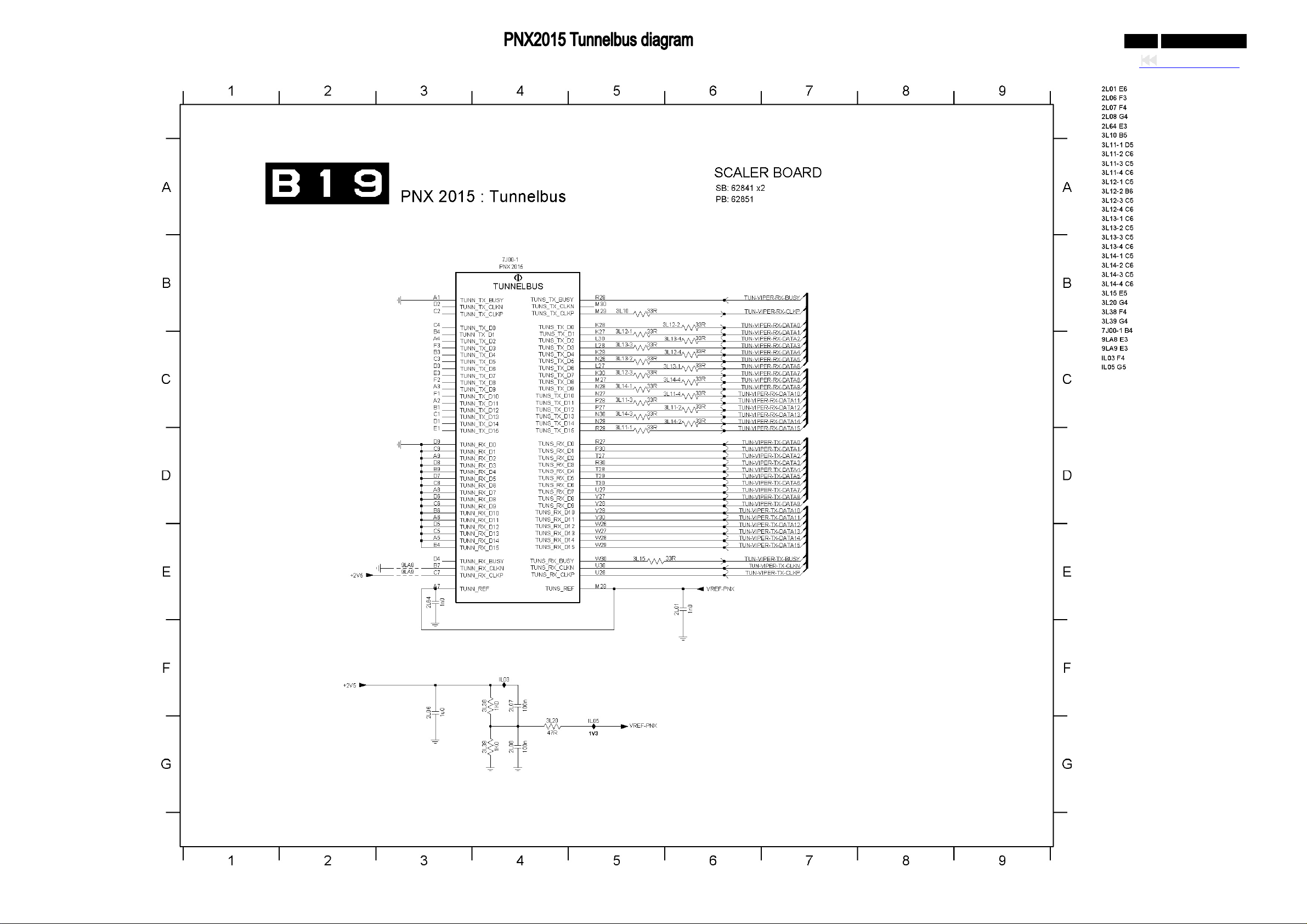
0-92-0 042MF231D/370
Back to cover
Page 93
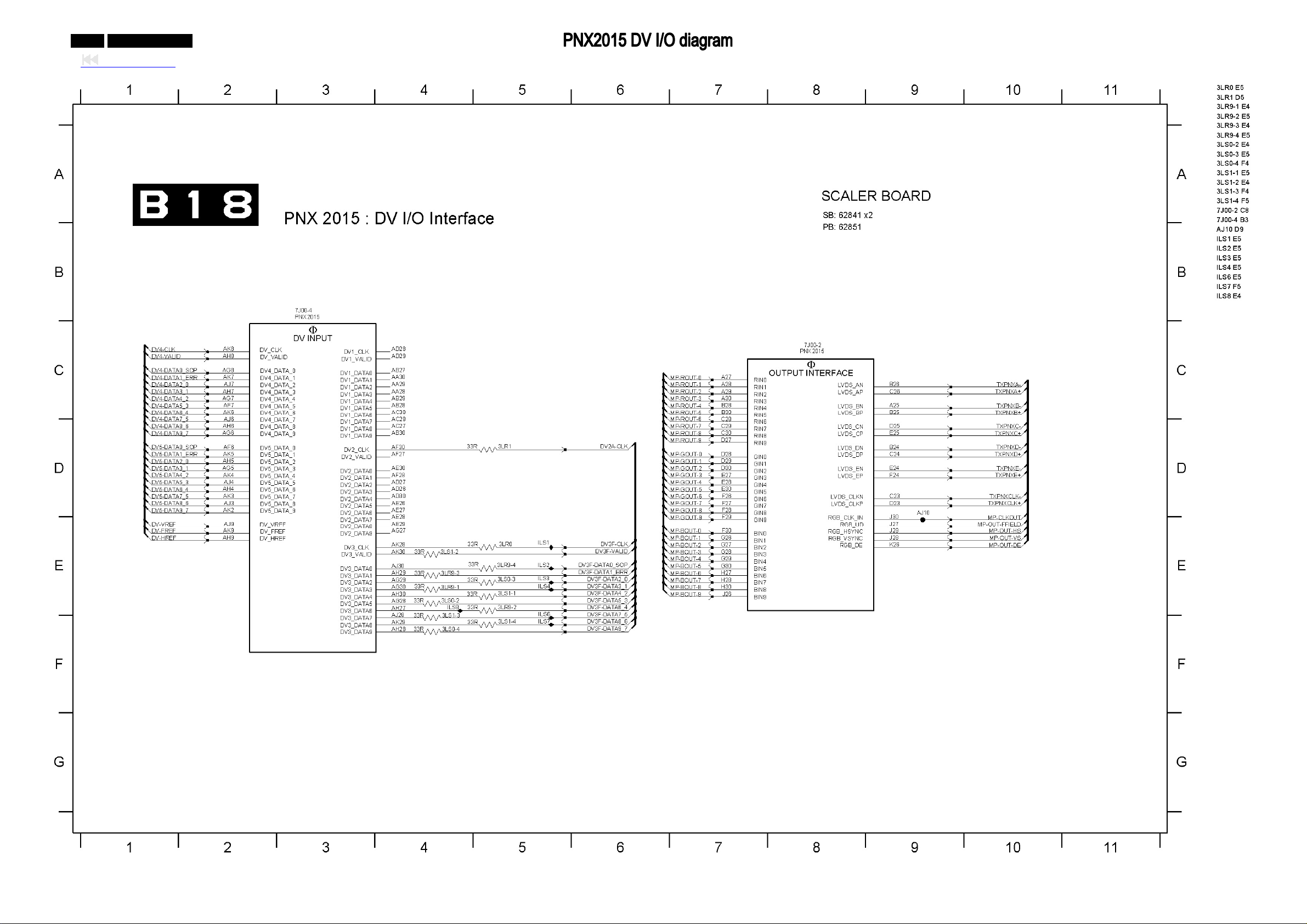
0-93-0 042MF231D/370
Back to cover
Page 94
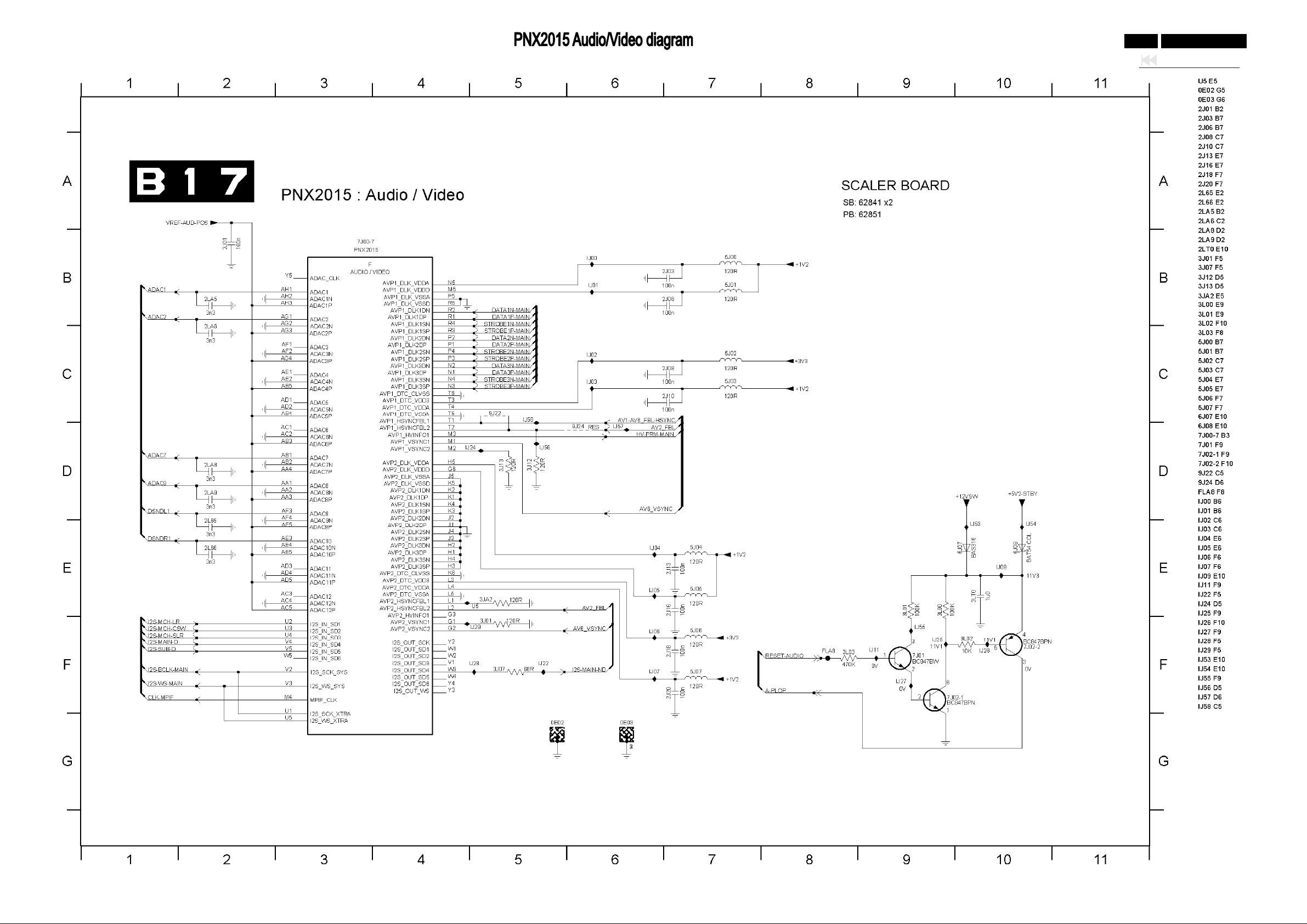
0-94-0 042MF231D/370
Back to cover
Page 95
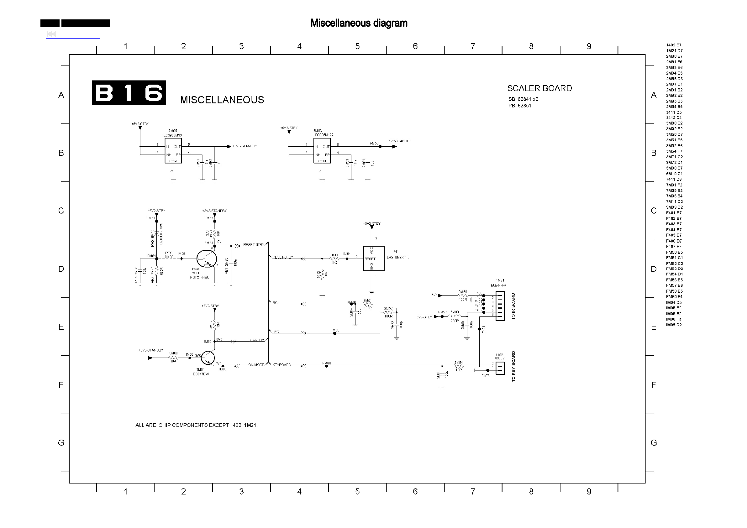
0-95-0 042MF231D/370
Back to cover
Page 96
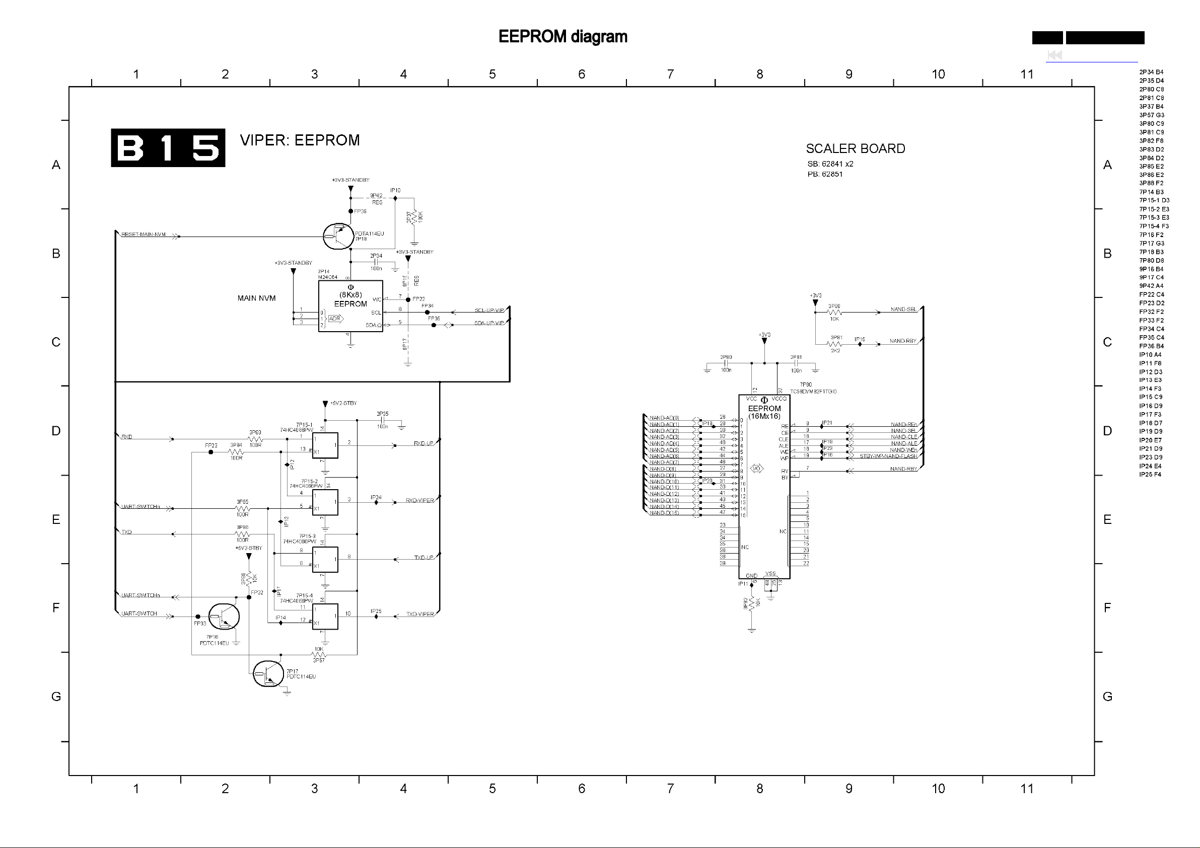
0-96-0 042MF231D/370
Back to cover
Page 97
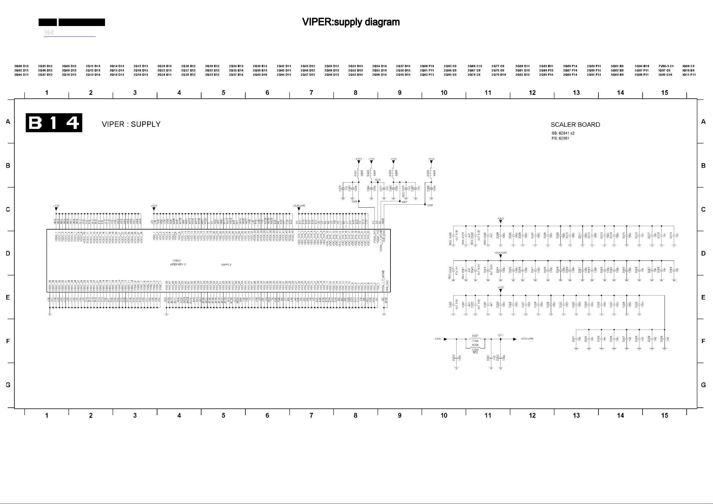
0-97-0 042MF231D/370
Back to cover
Page 98
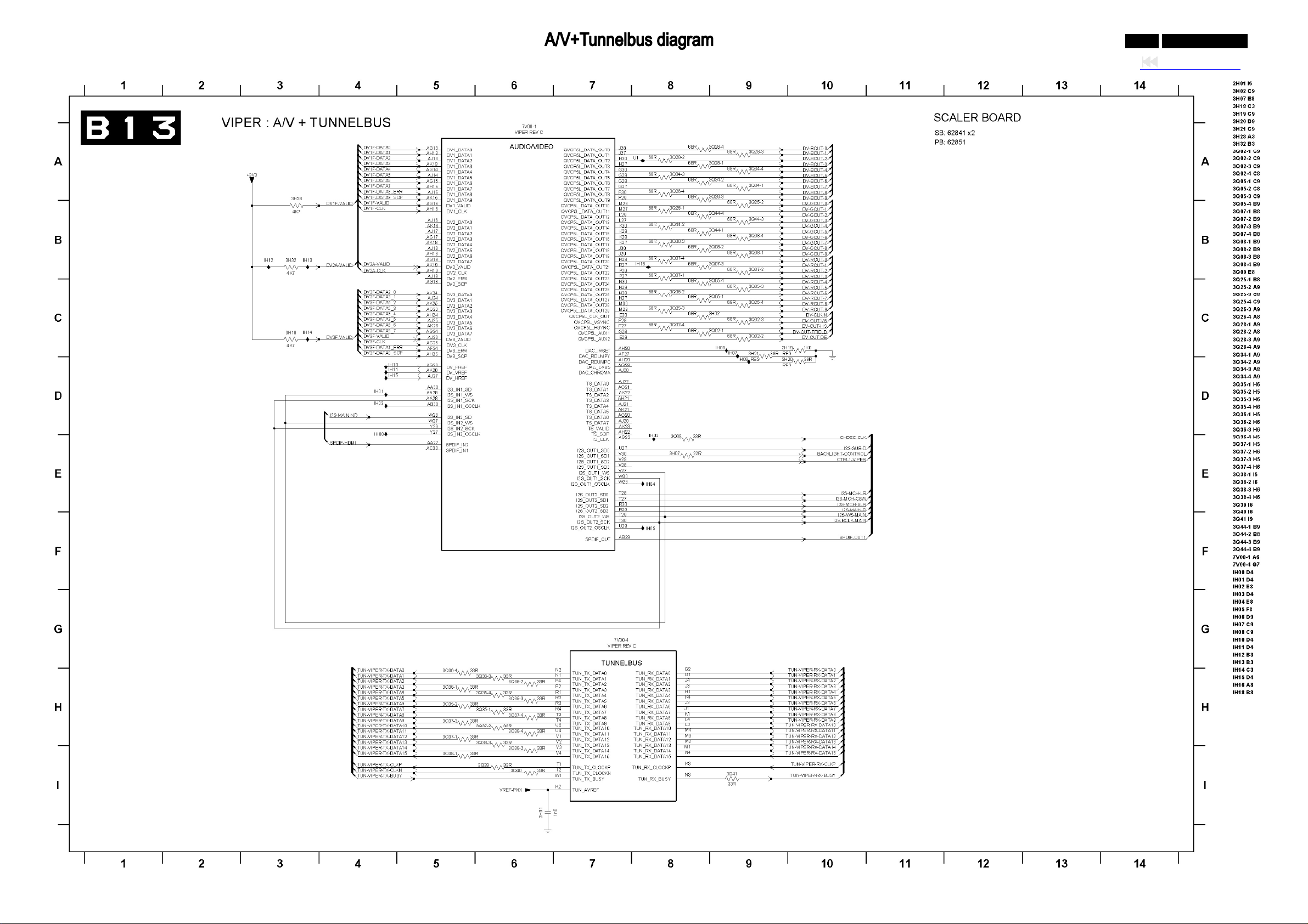
0-98-0 042MF231D/370
Back to cover
Page 99
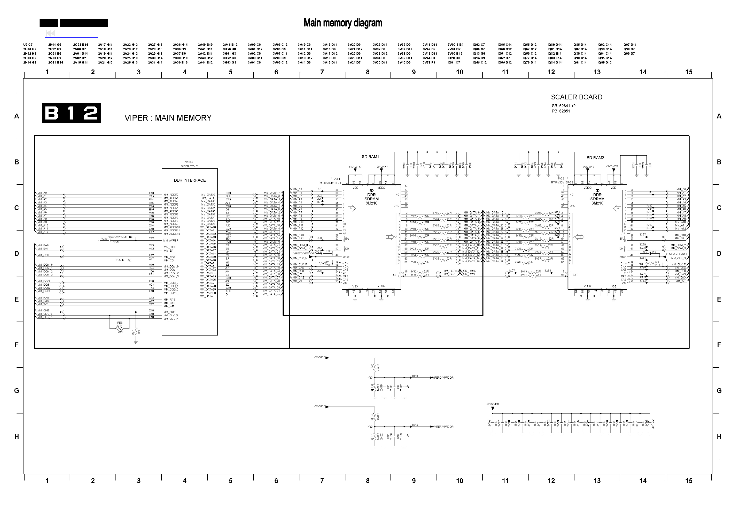
0-99-0 042MF231D/370
Back to cover
Page 100
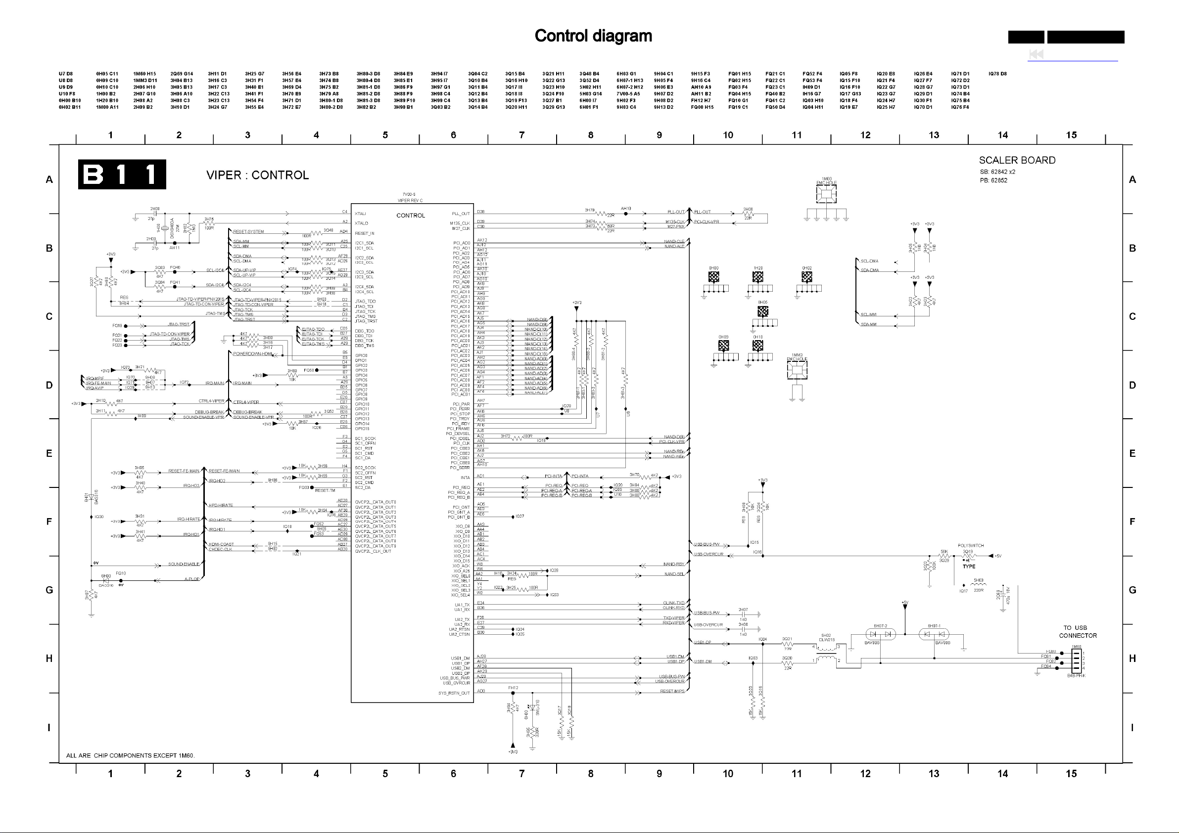
0-100-0 042MF231D/370
Back to cover
 Loading...