

Philips TE2.1E AA Service Manual
Colour Television
A
TE2.1E AA
Contents Page
Assembling/Disassembling Procedure 2
1. Technical Specifications, Connections and Chassis Overview 3
2. Safety Instructions, Warnings and Notes 4
3. Directions For Use 5
4. Mechanical Instructions 6
5. Service Modes Error Codes and Fault finding 7
6. Block Diagrams 12
7. Circuit Diagrams and PWB layouts 15
8. Alignments 29
9. Circuit Descriptions 38
10. Spare Part List 40
11. Revision list 44
© Copyright 2004 Philips Consumer Electronics B.V. Eindhoven, The Netherlands.
ll rights reserved. No part of this publication may be reproduced, stored in a
retrieval system or transmitted, in any form or by any means, electronic, mechanical,
photocopying, or otherwise without the prior permission of Philips
.
Published by JH 0467 Service PaCE Subject to modification EN 3122 785 14930

TE2.1E AA
EN 2
1. Technical Specifications, Connections and Chassis Overview
• Reception
100 programmes, PLL Tuning, Aerial Input : 75 Ohm
• TV Systems Off Air
PAL B/G + D/K + SECAM B/G + D/K, SECAM L/L’
• Add Systems Ext In
NTSC 3.58 + NTSC 4.43
• Sound Systems
B/G, D/K (FM A2+Nicam stereo), L/L’
• Screen Format
4:3
• Picture
16/9 Compress, 4:3, 4:3 Expand
• Sound
RMS Power Intern, 2 x 5W Stereo
• Teletext
10 page Top / Flof Text
• Connectors
Scart1: RGB + CVBS (rear Ext-1 )
Scart2: CVBS + SVHS (rear Ext-2 )
Headphone Front (3.5 mm)
Aerial Input (75 Ohm, rear)
• Mains Voltage
Official :220/240 VAC (± 10 %)
Real : 150/240 VAC (± 10 %)
Mains Frequency: 50 Hz (± 5 %)
• Languages OSD Menu
Turkish, English, French, German, Nederlands, Spanish, Italian.
• Power Consumption : 95W
• Stand-By Power Consumption : <8W
TE2.1E AA
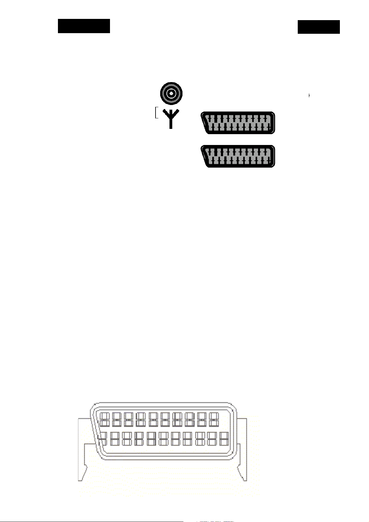
1.1 Connections
1.1.1 Rear Connections
EuroScart
1. Audio Output 1. right channel 0.5 VRMS/<1k0
2. Audio Input 1. right channel 0.5 VRMS/>10k0
3. Audio Output 2. left channel 0.5 VRMS/<1k0
4. GND (audio)
5. GND
6. Audio Input 2. left channel 0.5 VRMS/>10k0
7. RGB Input, blue (B)
8. Switch signal video (status)
9. GND
10. Reserved for clock signals (not connected)
11. RGB input, green (G)
12. Reserved for remote control
13. GND
14. GND switch signal RGB
15. RGB input, red (R) / Y
16. Switch Signal RGB
17. GND (video)
18. GND
19. Video Output 1Vpp/75 ohm
20. Video input 1Vpp/75 ohm / C
21. Shield
EN 3
EXT-2
EXT-1
Ht1
20 18 16 14 12 10 8 6 4 2
21 19 17 15 13 11 9 7 5 3 1

TE2.1E AA
2. Safety Instructions, Warnings and Notes
2.1 General
1. Use only the original spare parts with the same specifications for replacement.
2. Only the original fuse value should be used.
3. Safety components, indicated by the symbol, should be replaced by components
identical to the original ones.
4.
Main leads and connecting leads should be checked for external damage before
connection. Insulation must be checked. Parts contributing to the safety of the
product must not be damaged or obviously unsuitable. This is valid especially for
insulators and insulating parts.
5. Thermally loaded solder pads are to be sucked off and re-soldered.
6. Ensure that the ventilation slots are not obstructed.
7. Potentials as high as 25 KV are present when this receiver is operating. Operation
of the receiver outside the cabinet or with back cover removed involve a shock
hazard from the receiver.
8. Servicing should not be attempted by anyone who is not thoroughly familiar with
precautions necessary when working on high voltage equipment. Perfectly
discharge the high potential of the picture tube before handling it. The picture tube
is highly evacuated and if broken. Glass fragments will be violently expelled.
Always discharge the picture tube anode to the receiver chassis to keep of the
shock hazard before removing the anode cap.
9. Keep wire away from the high voltage or high temperature components.
10. When replacing a wattage resistor, keep the resistor 10mm away from the circuit
board.
EN 4
2.2 Handling the MOS chip components
MOS circuit requires special attention with regard to static charges. Static charges may
occur with any highly insulated plastics and can be transferred to
persons wearing clothes and shoes made of synthetic materials. Protective circuits on the
inputs and outputs of MOS circuits give protection to a limited extend only due to time of
reaction. Please observe the following instructions to protect the components against
ESD.
1. Keep MOS components in conductive package until they are used. Most
components must never be stored in styropor materials or plastic magazines.
2. Personnel must not touch the MOS components to avoid electrostatic discharging.
3. Hold the component by the body touching the terminals.
4. Use only grounded instruments for testing and processing purposes.
5. Remove or connect MOS Ics when operating voltage is disconnected.
6. Personnel in charge must make sure that they are connected with the same
potential as the mass of the set by a wristband with resistance.
2.3 X-Ray radiation precaution
Excessive high voltage can produce potentially hazardous X-RAY radiation. To avoid
such hazard, the high voltage must not be above the specified limit. The nominal
value of the high voltage of this receiver is 25KV at zero beam current (minimum
brightness) under 220 V AC power source. The high voltage must not under any
circumstance, exceed 30KV. It is recommended the reading of the high voltage to be
recorded as a part of the service record. It is important to use an accurate and reliable
high voltage meter. The primary source of X-RAY radiation in the TV receiver is the
picture tube. For continued X-RAY radiation protection, the replacement tube must be
exactly the same type tube as specified in the part list.

TE2.1E AA
3. Directions for use
DFU can be found on the internet: www.p4c.philips.com
EN 5

TE2.1E AA
EN 6
4. Mechanical Intructions
Disassembly procedure is explained as below. Before disassembling the TV set please
read the safety instructions and warning parts of the service manual.
• Turn off TV and plug the mains out
• Remove screws (10 pieces) to dismount the back cover
• Disconnect the following sockets to take the chassis out ;
¾Deflection cables
¾Degaussing coil
¾Speaker cable
¾Power cable
• Remove the ground cable localised between tube module and mass wire.
• Remove the CRT drive module from picture tube.
• Remove anode cable localised on the picture tube.
• Slide out the chassis through the guides (no screws, straps or other fixing).
Please follow the assembly instructions explained below;
• Before inserting the chassis into guides, check the control buttons in front of the
chassis. In case of misplacement of control buttons place them into correct position.
• Slide the chassis into guides until the connection cables could be reached to their
sockets.
• Plug in the power cable socket to KP03.
• Plug in the degauss cable socket to KP02.
• Plug in the speaker cable socket to KA04.
• Place the CRT drive module on picture tube.
• Slide the chassis completely on its place. Be careful about control buttons.
• Plug in the deflection cable socket to KD02 and KD01.
• Place the anode cable to picture tube. Be careful about high voltage!
¾CRT drive module must be grounded via mass cable.
• Place the back cover back to its place.(10 screws)
• Plug the mains in.
• Turn on the TV.
TE2.1E AA
5. Service Modes, Error Codes and Fault finding
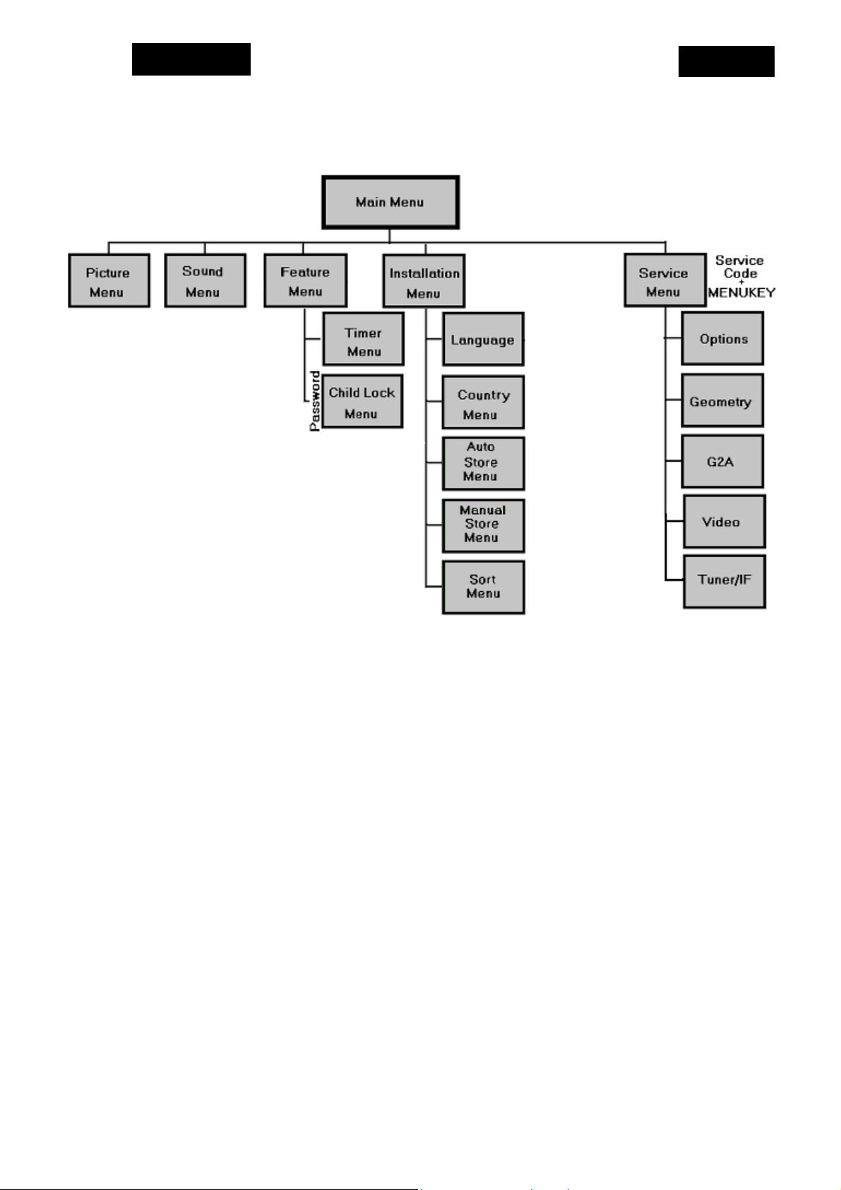
5.1 Menu Structure
EN 7
General Menu Options
To minimise the number of keys on the remote control unit, less frequently used
functions are accessible only via simple menus. The menus are controlled by the
following keys;
x “MENU” button makes the Main Menu displayed. Previous menu is displayed at
each press of MENU button, when any menu OSD is displaying.
x Navigation Up / Down keys are used for selection of the previous and next item
on the current menu OSD. Selected item is highlighted.
x Left and Right are used for changing the right side value of the highlighted menu
item if the item is not a submenu. Beside that Right button also is used as OK
button.
x Menu Right key is used to select a highlighted item, generally for displaying
submenu OSDs.
x Navigation Up / Down buttons are used for picture format 16:9 Compress, 4:3 or
4:3 Expand

TE2.1E AA
5.2 Menu Control
Main Menu
Features
Picture Menu
EN 8
Picture
Sound
Installation
Brightness 64 Steps
Colour 64 Steps
Contrast 64 Steps
Sharpness 64 Steps
Hue 64 Steps (for NTSC only)
Colour Temp : Normal, Warm, Cool
Store Stored
Sound Menu
Features Menu
Timer Menu
Parental Control Menu
Treble 64 Steps
Bass 64 Steps
Balance L-32 ..0.. 32-R
AVL : On, Off
Store Stored
Timer
Childlock : On, Off
Parental Cont.
Ext-1 : VCR, Decoder/DVD
Ext-2 : VCR, Decoder/DVD
Sleep : Off, 15, 30, 45,…, 120
Time XX : XX (am, pm)
Start Time XX : XX
Program No : 0 … 99, SVHS2, Ext-2, Ext-1
Activate : Off, Once, Daily
Lock Off, XXX
Pr. Lock Off, XXX
Installation Menu
Language : English, French, German, Turkish, Dutch,
Italian, Spanish
Country : …, A, B, CH, D, DK, E, F, FI, GB, GR, I, N,
NL, P, IRL, L, S, TR
Auto Store
Manual Store
Sort
Name
TE2.1E AA
EN 9
Auto Store Menu
Program No
TV
¸¸¸¸¸¸¸¸¸¸¸¸¸¸¸
Manual Store Menu
System Europe, France, West Europe, East
Europe
Search XXX.25 MHz
Program No XX
Fine Tune -10 … +10 gauge
Store Stored
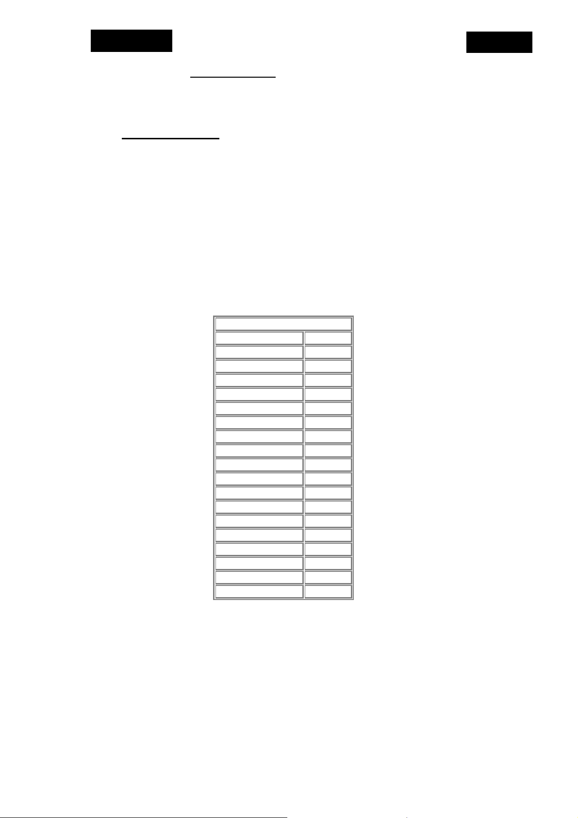
5.3 Country List
…, A (Austria), B (Belgium), CH (Switzerland), D (Germany), DK (Denmark), E (Spain), F
(France), FI (Finland), GB (UK), GR (Greece), I (Italy), N (Norway), NL (Netherlands), P
(Portugal), IRL (Ireland), L (Luxemburg), S (Sweden), TR (Turkey)
Philips 28” 4:3 FS
Austria
Belgium
Switzerland
Germany
Denmark
Spain
France
Finland
United Kingdom
Greece
Italy
Norway
Netherlands
Portugal
Ireland
Luxemburg
Sweden
Turkey
Other
A
B
CH
D
DK
E
F
FI
GB
GR
I
N
NL
P
IRL
L
S
TR
...
TE2.1E AA
N
NON
N
N
N
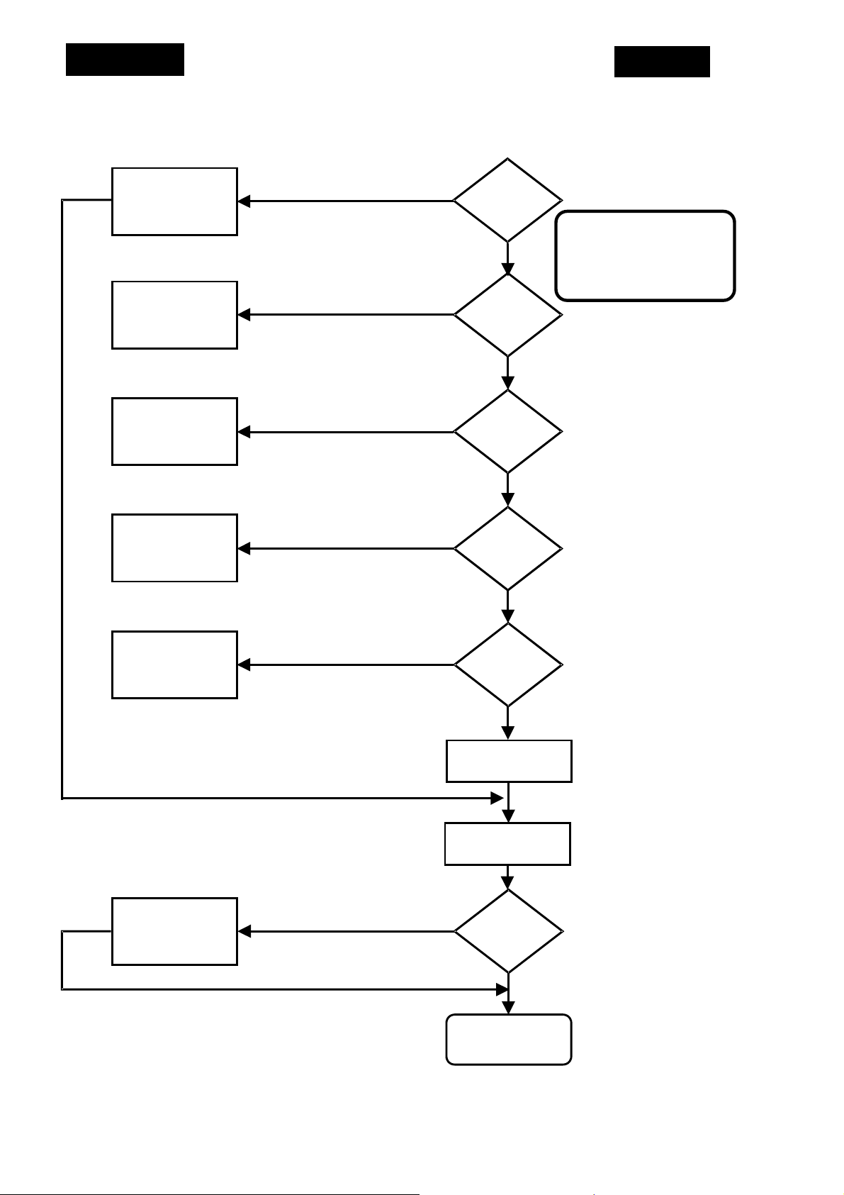
5.4 Fault finding diagram of Power supply
EN 10
DP01 - 04
CP01 - 04
CP06, TP01
RP07, RP05
open and
short circuit
RP06
RP11, DP07
YES
YES
YES
Fuse
FP01
Defective
O
Voltage
at
drain of
TP01
YES
Voltage at
IP01 pin 11
< 1V
O
start-up
voltage
(6)
pin 14
< 8V
Switched mode Power
Supply defective, +145V
is missing or level is
wrong
TP01
VAP2, RP03, DP19
YES
start-up voltage
varies ca. 8V
Measure
O
adjustable with
O
O
IP01
+145V
VAP2
YES
Control range of
switched-mode
power supply
TE2.1E AA
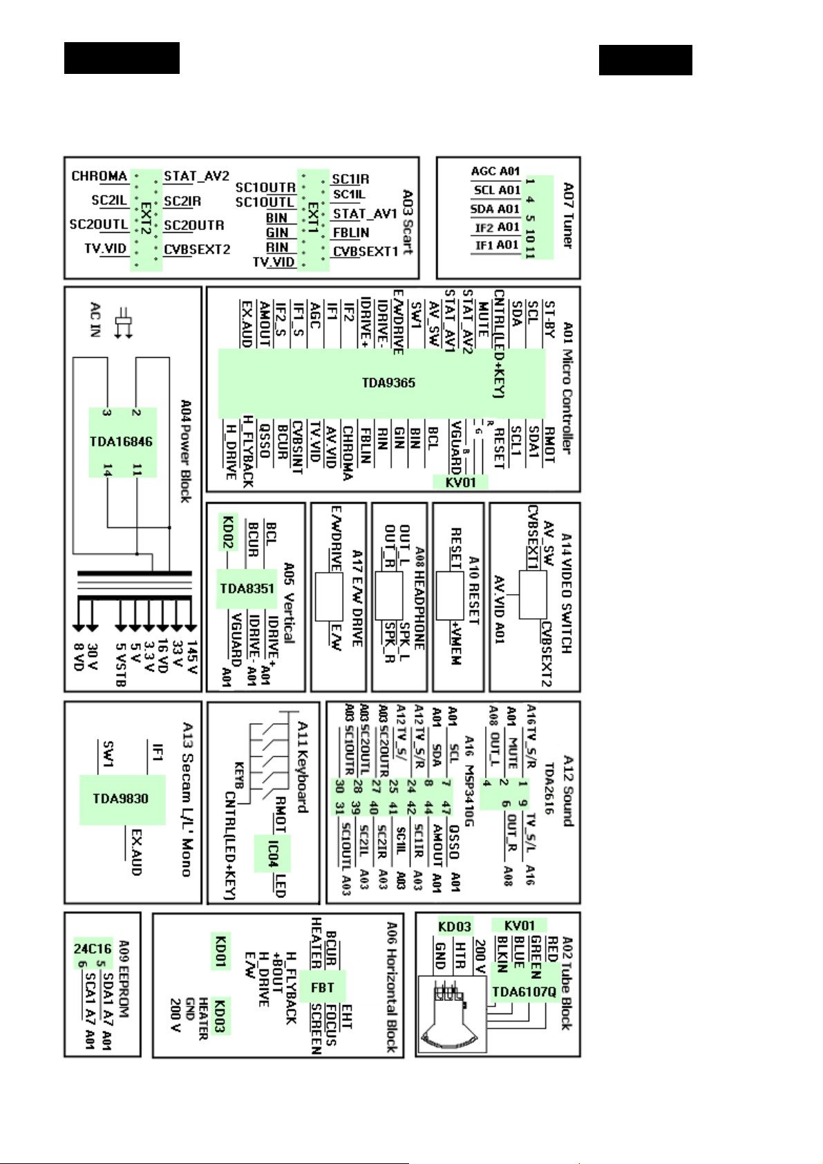
5.5 Chassis Diagram
EN 11
TE2.1E AA
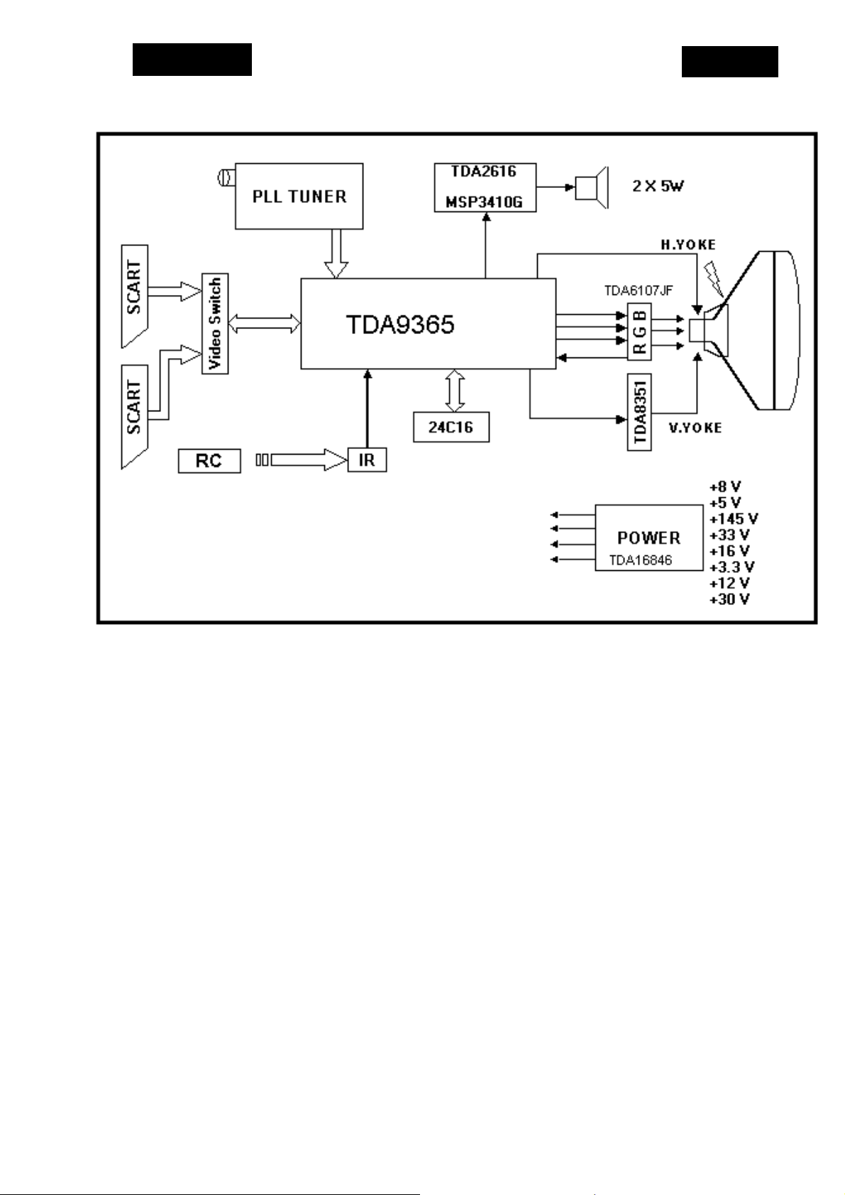
6. Block Diagrams
6.1 Block diagram
EN 12
TE2.1E AA
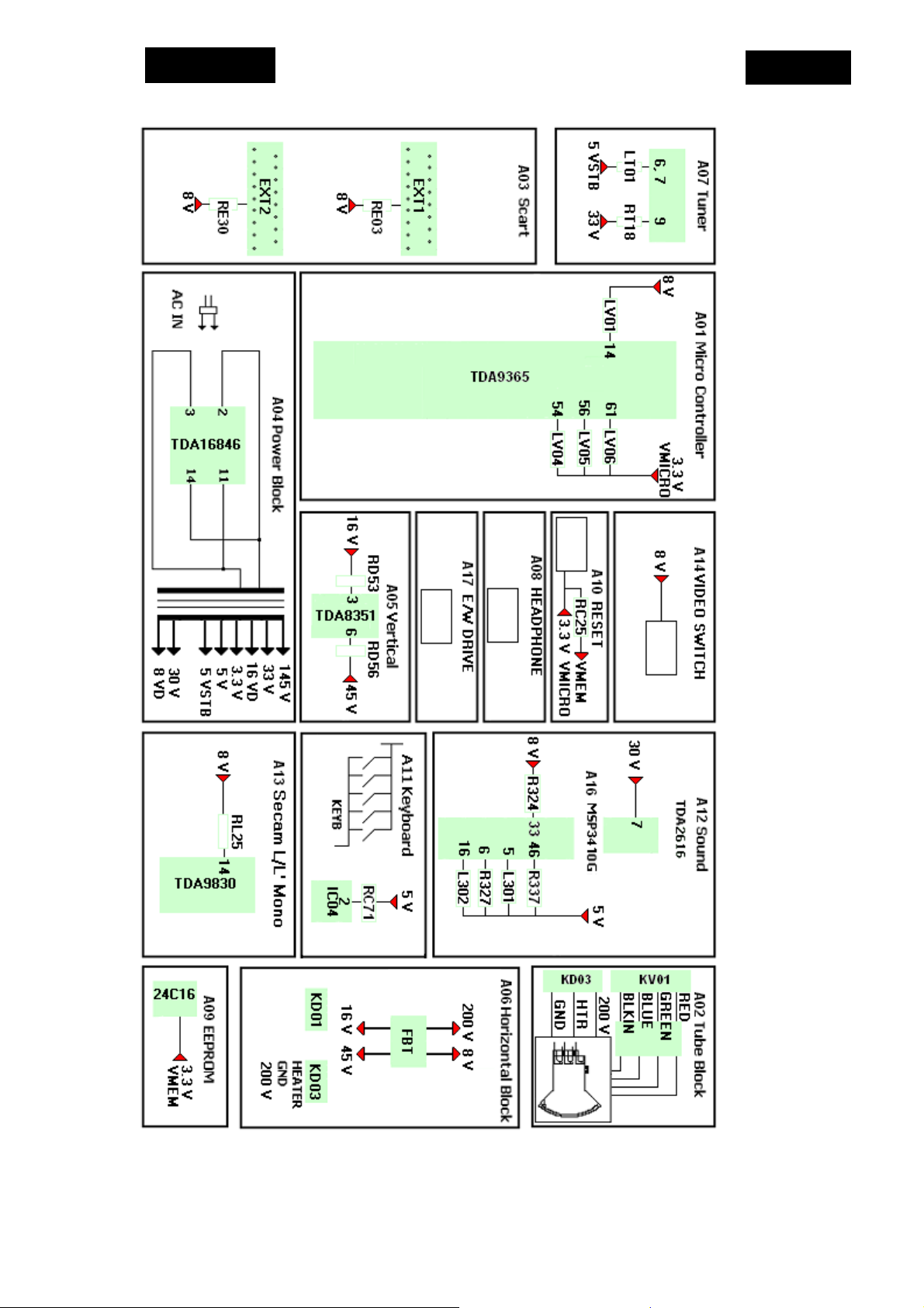
6.2 Supply Voltage Overview
EN 13
TE2.1E AA
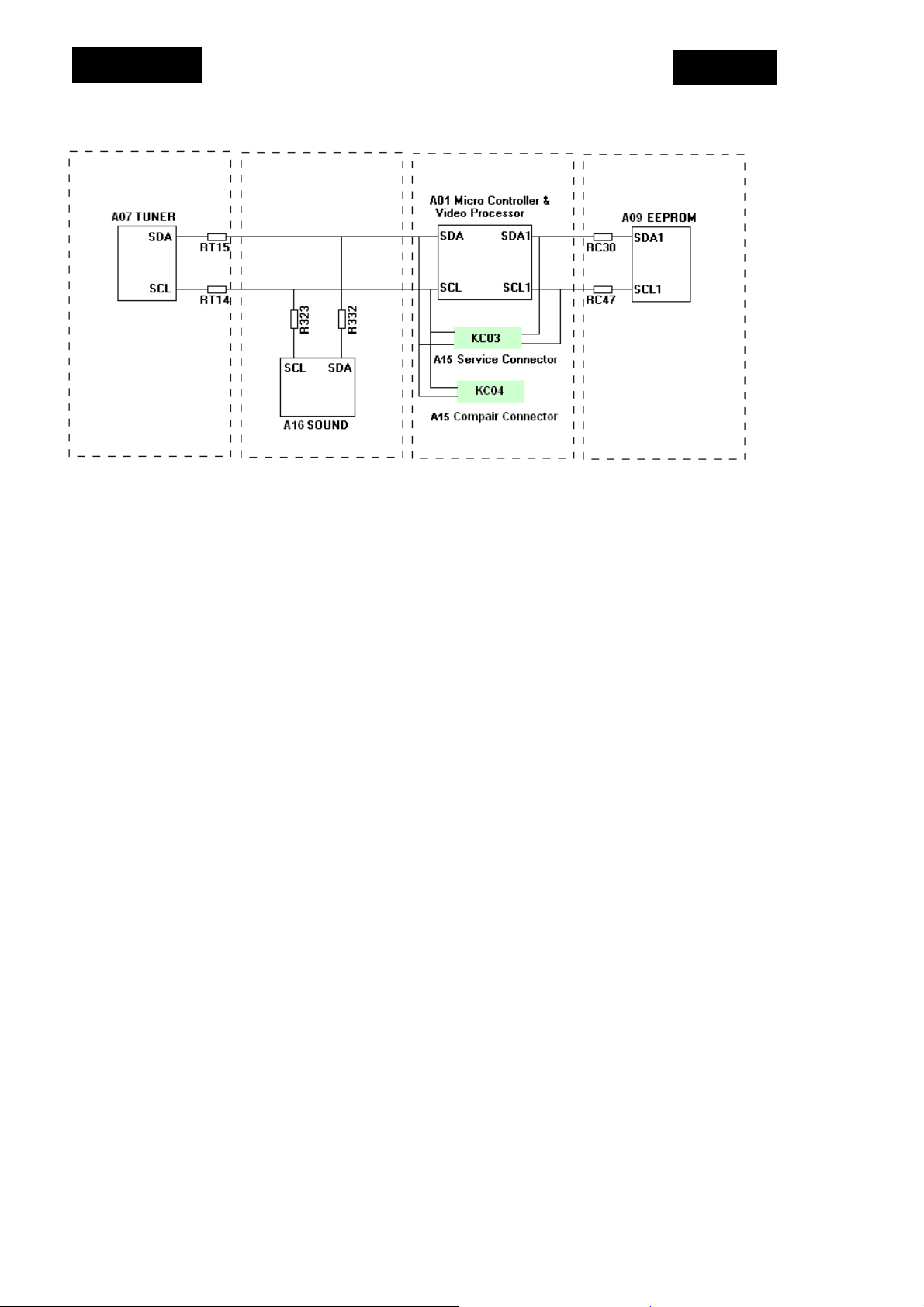
6.3 I2C BusOverview
EN 14
 Loading...