

Philips TDVD2.1E AA Service Manual
Colour Television Chassis
TDVD2.1E
AA
CL 36532059_000.eps
050803
Contents Page Contents Page
1. Technical Specifications, Connections, and Chassis
Overview 2
2. Safety Instructions, Warnings, and Notes 5
3. Directions for Use 7
4. Mechanical Instructions 15
5. Service Modes, Error Codes, and Fault Finding 16
6. Block Diagrams, Test Point Overviews, and
Waveforms
Block Diagram 19
I2C Bus Interconnection Diagram 20
Chassis Diagram 20
Supply Voltage Diagram 21
7. Circuit Diagrams and PWB Layouts Diagram PWB
Main Panel: Tuner (A1) 22 28-29
Main Panel: EEPROM (A2) 22 28-29
Main Panel: Audio Amplifier (A3) 22 28-29
Main Panel: Vertical (A4) 23 28-29
Main Panel: Video Processor (A5) 23 28-29
Main Panel: DVD AV (A6) 24 28-29
Main Panel: DVD OUT (A8) 24 28-29
Main Panel: Keyboard (A10) 24 28-29
Main Panel: SCART (A11) 24 28-29
Main Panel: u-Controller (A7) 25 28-29
Main Panel: Power Supply (A9) 26 28-29
Main Panel: Horizontal (A12) 27 28-29
Picture Tube Panel (B) 30 30
LED Panel (C) 31 31
Front AV Panel (D) 31 31
Line Out Panel (E) 32 32
Mains Switch Panel (F) 32 32
8. Alignments 33
9. Circuit Description and Abbreviation List 36
List of Abbreviations 36
IC Data Sheets 37
10. Spare Parts List 43
11. Revision List 46
©
Copyright 2005 Philips Consumer Electronics B.V. Eindhoven, The Netherlands.
All rights reserved. No part of this publication may be reproduced, stored in a
retrieval system or transmitted, in any form or by any means, electronic,
mechanical, photocopying, or otherwise without the prior permission of Philips.
Published by JH 0569 Service PaCE Printed in the Netherlands Subject to modification EN 3122 785 14171
EN 2 TDVD2.1E AA1.
Technical Specifications, Connections, and Chassis Overview
1. Technical Specifications, Connections, and Chassis Overview
Index of this chapter:
1.1 Technical Specifications
1.2 Connection/Control Facilities
1.3 Chassis Overview
1.1 Technical Specifications
1.1.1 Reception
Tuning System : PLL
Colour Systems : PAL
: SECAM
Sound System : 2SC BG
: NICAM BGDKIL
A/V Connections : NTSC 3.58
: NTSC 4.43
Channel Selections : 100 presets
: UVSH
IF Frequency : B/G, D/K, L: 38.9 MHz
: L': 33.4 MHz
: I: 39.5 MHz
Aerial Input : 75 Ohm
1.1.2 DVD module
Disc formats : CD Audio
: MP3 Audio
: DVD Audio
: CD (R/RW)
:CVD
: (S) VCD
:DVCD
:DVD (+R/RW)
: DVD (-R/RW)
: DVD-Video
Rotational speed : 3.9 - 5.5 x CD
: 1.6 - 2.4 x DVD
Data transfer rate : 2216 - 3324 kB/s for
DVD
: 672 - 947 kB/s for CD
Avg. access time : 320 ms (DVD). 420
ms (CD) typical
Data buffer capacity : 256 Kbytes
1.2 Connection/Control Facilities
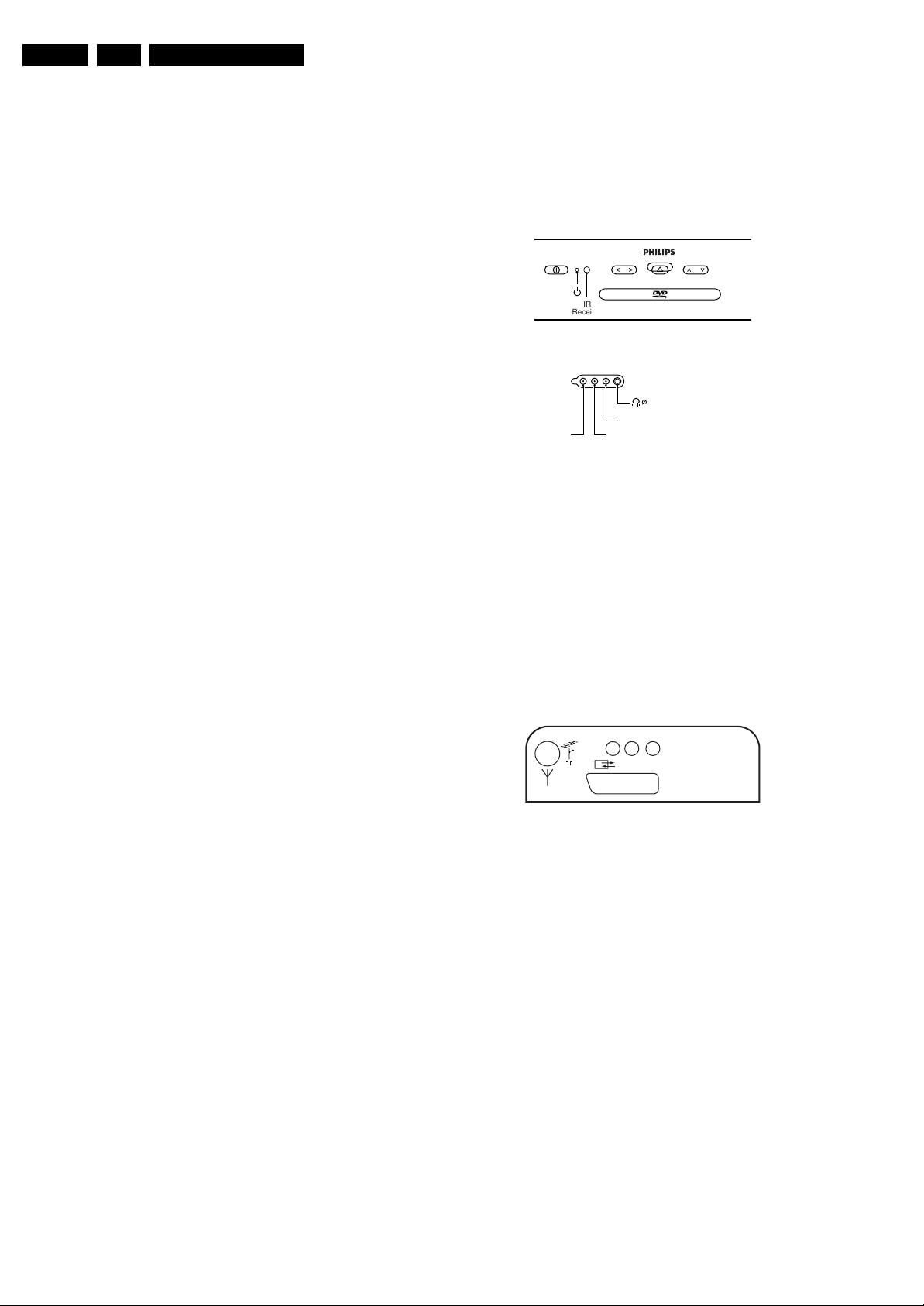
1.2.1 TV Side Connections and Front Control
FRONT CONTROL
PHILIPS
- VOLUME + - PROGRAM +
IR
Receiver
SIDE I/O
3.5
VIDEO
Figure 1-1 Side connections and Front control
Cinch (Input)
1 -CVBS 1 Vpp / 75 Ω jq
2 -Audio - L 0.5 Vrms / 10 kΩ jq
3 -Audio - R 0.5 Vrms / 10 kΩ jq
Mini Jack: Headphone - Out
- Headphone 32 - 600 Ω / 10 mW rt
1.2.2 TV Rear Connections
REAR CONNECTIONS
AUDIO R
AUDIO L
EURO-AV
CL 36532059_001.eps
PCMA/RA/L
CL 26532120_002.eps
310703
251002
1.1.3 Miscellaneous
Audio Output (RMS) : 2 x 3 W
Mains Voltage : 150 - 240 V (± 10 %)
Mains Frequency : 50 (± 5 %)
Power Consumption : 50 W
Standby Power Consumption : < 3 W
Figure 1-2 Rear connections
Aerial - In
- IEC - type Coax, 75 Ω D
Cinch (Output)
1 -Audio - L 0.5 Vrms / 1 kΩ kq
2 -Audio - R 0.5 Vrms / 1 kΩ kq
3 -Digital Audio SPDIF kq

Technical Specifications, Connections, and Chassis Overview
EN 3TDVD2.1E AA 1.
Euro AV
121
CL96532137_056.eps
Figure 1-3 SCART connector
1 -Audio - R 0.5 Vrms / 1 kOhm k
2 -Audio - R 0.5 Vrms / 10 kOhm j
3 -Audio - L 0.5 Vrms / 1 kOhm k
4 -Audio Ground H
5 -Blue Ground H
6 -Audio - L 0.5 Vrms / 10 kOhm j
7 -Blue 0.7 Vpp / 75 Ohm j
8 -CVBS-status 0 - 1.3 V: INT
4.5 - 7 V: EXT 16:9
9.5 - 12 V: EXT 4:3
9 -Green Ground H
10 -
11 - Green 0.7 Vpp / 75 Ohm j
12 -
13 - Red Ground H
14 - CVBS status Ground H
15 - Red 0.7 Vpp / 75 Ohm j
16 - RGB status 0 - 0.4 V: INT
1 - 3 V: EXT / 75 Ohm j
17 - CVBS Ground H
18 - RGB status Ground H
19 - CVBS-out 1 Vpp / 75 Ohm k
20 - CVBS-in 1 Vpp / 75 Ohm j
21 - Shielding Ground H
202
171199
Slave Interface Connector (CN7)
1-INTOR k
2-GND H
3 -VDATAIN k
4 -VDATAOUT k
5-VCLK k
6-VSTB k
External A/V Interface Connector(CN8)
1-POWER k
2-STOP k
3 - EJECT k
4-LED1 k
5 - NEXT k
6-BACK k
7 - PLAY k
8-LED2 k
9 - EXT_IF_! k
10 - EXT_IN_2 k
11 - Ground H
1.2.3 DVD Module Connections
DC Power Connector (CN1)
1 - Supply voltage + 12 V
2 -Ground GND H
3-Supply voltage + 3.3 V
4 - Ground (analogue) A-GND H
5 - Ground (digital) D-GND H
6 - Supply voltage + 5 V
7 - Power Control Active high
A/V and DAIC Output (CN6)
1 - R/R (PCM3) Rear Right Audio (Audio Data 3) k
2 - AGND Audio Ground H
3 - R/L (PCM2) Rear Left Audio (Audio Data 2) k
4 - CEN (PCM1) Centre Audio (Audio Data 1) k
5 - A-GND Audio Ground H
6 - S/W (PCM0) Sub Woofer (Audio Data 0) k
7 - F/R (SCK) Front Right Audio (System clock) k
8 - AGND Audio Ground H
9 - F/L (BCK) Front Left Audio (Audio bit clock) k
10 - MUTE (LRCK) Mute for Audio (Audio L/Rch clock) k
11 - SPDIF Digital Audio k
12 - D-GND Digital Ground H
13 - CVBS 1 Vpp / 75 Ohm k
14 - VGND Video Ground H
15 - Y 1 Vpp / 75 Ohm k
16 - VGND Video Ground H
17 - C 0.3 Vpp / 75 Ohm k
18 - VGND Video Ground H
19 - G(Y) 0.7 Vpp / 75 Ohm k
20 - B(Cb) 0.7 Vpp / 75 Ohm k
21 - R(Cr) 0.7 Vpp / 75 Ohm k
22 - VGND Video Ground H
23 - VID_S/W Video switching k
24 - TV_S/W TV switching k
25 - MODE1 SCL or TXD k
26 - MODE2 SDA or RXD k
EN 4 TDVD2.1E AA1.
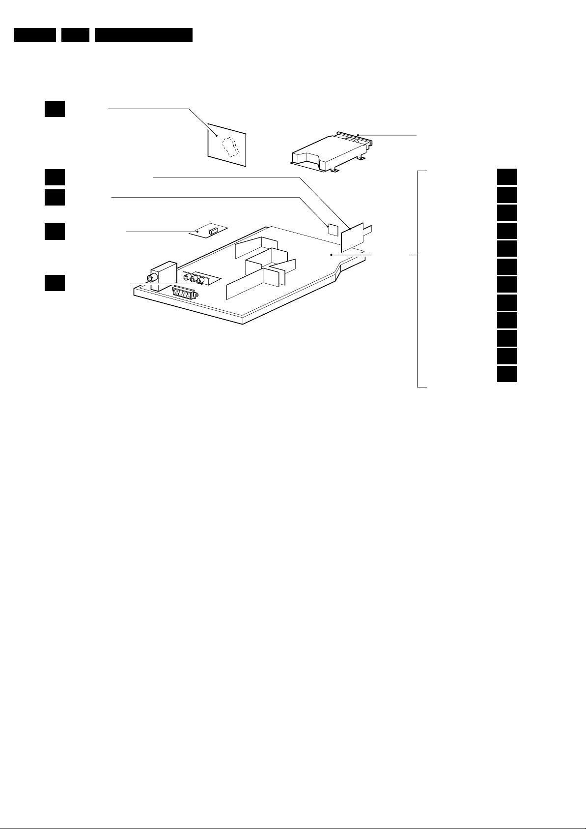
1.3 Chassis Overview
CRT PANEL
B
Technical Specifications, Connections, and Chassis Overview
DVD ENGINE
MAINS SWITCH PANEL
F
LED PANEL
C
SIDE AV PANEL
D
LINE OUT PANEL
E
Figure 1-4 PWB location
MAIN
CHASSIS
PANEL
TUNER
EEPROM
AUDIO AMPLIFIER
VERTICAL
VIDEO PROCESSOR
DVD AV
µ-CONTROLLER
DVD OUT
POWER SUPPLY
SCART
KEYBOARD
HORIZONTAL
CL 36532059_002.eps
A1
A2
A3
A4
A5
A6
A7
A8
A9
A10
A11
A12
040803

Safety Instructions, Warnings, and Notes
2. Safety Instructions, Warnings, and Notes
EN 5TDVD2.1E AA 2.
Index of this chapter:
2.1 Safety Instructions
2.2 Maintenance Instructions
2.3 Warnings
2.4 Notes
2.1 Safety Instructions
Safety regulations require that during a repair:
• Due to the chassis concept, a part of the circuitry is 'hot'.
Therefore, connect the set to the mains via an isolation
transformer.
• Replace safety components, indicated by the symbol
only by components identical to the original ones. Any
other component substitution (other than original type) may
increase risk of fire or electrical shock hazard.
• Wear safety goggles when you replace the CRT.
Safety regulations require that after a repair, you must return
the set in its original condition. Pay, in particular, attention to
the following points:
• General repair instruction: as a strict precaution, we advise
you to re-solder the solder connections through which the
horizontal deflection current is flowing. In particular this is
valid for the:
1. Pins of the line output transformer (LOT).
2. Fly-back capacitor(s).
3. S-correction capacitor(s).
4. Line output transistor.
5. Pins of the connector with wires to the deflection coil.
6. Other components through which the deflection current
flows.
Note: This re-soldering is advised to prevent bad connections
due to metal fatigue in solder connections, and is therefore only
necessary for television sets more than two years old.
• Route the wire trees and EHT cable correctly and secure
them with the mounted cable clamps.
• Check the insulation of the mains cord for external
damage.
• Check the strain relief of the mains cord for proper function,
to prevent the cord from touching the CRT, hot
components, or heat sinks.
• Check the electrical DC resistance between the mains plug
and the secondary side (only for sets that have an isolated
power supply). Do this as follows:
1. Unplug the mains cord and connect a wire between the
two pins of the mains plug.
2. Turn on the main power switch (keep the mains cord
unplugged!).
3. Measure the resistance value between the pins of the
mains plug and the metal shielding of the tuner or the
aerial connection of the set. The reading should be
between 4.5 MΩ and 12 MΩ.
4. Switch the TV 'off' and remove the wire between the
two pins of the mains plug.
• Check the cabinet for defects, to prevent the possibility of
the customer touching any internal parts.
h,
Output Power : 20 mW (DVD+RW
writing)
: 0.8 mW (DVD
reading)
: 0.3 mW (VCD/CD
reading)
Beam divergence : 60 degree
Figure 2-1
Note: Use of controls or adjustments or performance of
procedure other than those specified herein, may result in
hazardous radiation exposure. Avoid direct exposure to beam.
2.2 Maintenance Instructions
We recommend a maintenance inspection carried out by
qualified service personnel. The interval depends on the usage
conditions:
• When a customer uses the set under normal
circumstances, for example in a living room, the
recommended interval is three to five years.
• When a customer uses the set in an environment with
higher dust, grease, or moisture levels, for example in a
kitchen, the recommended interval is one year.
• The maintenance inspection includes the following actions:
1. Perform the 'general repair instruction' noted above.
2. Clean the power supply and deflection circuitry on the
chassis.
3. Clean the picture tube panel and the neck of the picture
tube.
2.3 Warnings
2.3.1 General
• In order to prevent damage to ICs and transistors, avoid all
high voltage flashovers. In order to prevent damage to the
picture tube, use the method shown in Fig. 2-2, to
discharge the picture tube. Use a high voltage probe and a
multi-meter (position V
reading is 0 V (after approx. 30 s).
V
). Discharge until the meter
DC
2.1.1 Laser Safety
This unit employs a laser. Only qualified service personnel may
remove the cover, or attempt to service this device (due to
possible eye injury).
Laser Device Unit
Type : Semiconductor laser
GaAlAs
Wavelength : 650 nm (DVD)
: 780 nm (VCD/CD)
CL96532156_040.eps
140501
Figure 2-2 Discharge picture tube
• All ICs and many other semiconductors are susceptible to
electrostatic discharges (ESD, symbol w). Careless
handling during repair can reduce life drastically. Make

EN 6 TDVD2.1E AA2.
sure that, during repair, you are connected with the same
potential as the mass of the set by a wristband with
resistance. Keep components and tools also at this
potential. Available ESD protection equipment:
– Complete kit ESD3 (small tablemat, wristband,
connection box, extension cable and ground cable)
4822 310 10671.
– Wristband tester 4822 344 13999.
• Together with the deflection unit and any multi-pole unit,
flat square picture tubes form an integrated unit. The
deflection and the multi-pole units are set optimally at the
factory. We do not recommend adjusting this unit during
repair.
• Be careful during measurements in the high voltage
section and on the picture tube.
• Never replace modules or other components while the unit
is 'on’.
• When you align the set, use plastic rather than metal tools.
This will prevent any short circuits and the danger of a
circuit becoming unstable.
2.3.2 Laser
• The use of optical instruments with this product, will
increase eye hazard.
• Only qualified service personnel may remove the cover or
attempt to service this device, due to possible eye injury.
• Repair handling should take place as much as possible
with a disc loaded inside the player.
• Text below is placed inside the unit, on the laser cover
shield:
Safety Instructions, Warnings, and Notes
CAUTION VISIBLE AND INVISIBLE LASER RADIATION WHEN OPEN AVOID EXPOSURE TO BEAM
ADVARSEL SYNLIG OG USYNLIG LASERSTRÅLING VED ÅBNING UNDGÅ UDSÆTTELSE FOR STRÅLING
ADVARSEL SYNLIG OG USYNLIG LASERSTRÅLING NÅR DEKSEL ÅPNES UNNGÅ EKSPONERING FOR STRÅLEN
VARNING SYNLIG OCH OSYNLIG LASERSTRÅLNING NÄR DENNA DEL ÄR ÖPPNAD BETRAKTA EJ STRÅLEN
VARO! AVATTAESSA OLET ALTTIINA NÄKYVÄLLE JA NÄKYMÄTTÖMÄLLE LASER SÄTEILYLLE. ÄLÄ KATSO SÄTEESEEN
VORSICHT SICHTBARE UND UNSICHTBARE LASERSTRAHLUNG WENN ABDECKUNG GEÖFFNET NICHT DEM STRAHL AUSSETSEN
DANGER VISIBLE AND INVISIBLE LASER RADIATION WHEN OPEN AVOID DIRECT EXPOSURE TO BEAM
ATTENTION RAYONNE MENT LASER VISIBLE ET INVISIBLE EN CAS D'OUVERTURE EXPOSITION DANGEREUSE AU FAISCEAU
!
Figure 2-3
2.4 Notes
• Measure the voltages and waveforms with regard to the
chassis (= tuner) ground (H), or hot ground (I), depending
on the tested area of circuitry.
• The voltages and waveforms shown in the diagrams are
indicative. Measure them in the Service Default Mode (see
chapter 5) with a colour bar signal and stereo sound (L: 3
kHz, R: 1 kHz unless stated otherwise) and picture carrier
at 475.25 MHz (PAL) or 61.25 MHz (NTSC, channel 3).
• Where necessary, measure the waveforms and voltages
with (D) and without (E) aerial signal. Measure the
voltages in the power supply section both in normal
operation (G) and in standby (F). These values are
indicated by means of the appropriate symbols.
• The picture tube panel has printed spark gaps. Each spark
gap is connected between an electrode of the picture tube
and the Aquadag coating.
• The semiconductors indicated in the circuit diagram and in
the parts lists, are interchangeable per position with the
semiconductors in the unit, irrespective of the type
indication on these semiconductors.

3. Directions for Use
You can download this information from the following websites:
http://www.philips.com/support
http://www.p4c.philips.com
Directions for Use
EN 7TDVD2.1E AA 3.

EN 8 TDVD2.1E AA3.
12
Mark
MENU
OK
”
P
564
879
0
¢
∫
ù
¤
ª
3
--
++
.
[
Zoom DVD Menu
Search
A-B
Repeat Clear
Subtitle
Fast
Skip
Ω™
Ë
›
ÓŸ
∏
Æ
∆
TV/DVD
Audio
-
Á
Ø
Ê
fl
3
The remote control keys
TV: Information Screen
To display / hide the programme
number,name (if there is one) sound
mode *, and the time remaining on
the timer.
DVD:Info. on playing (p.10)
DVD keys (p. 10,12)
TV: teletext keys (p.8)
Rewind and fast forward (p.10)
Stop, Eject (p. 10)
Cursor
These four keys navigate the menus.
Menu
To call or close menus
Selection of EXT sockets
Press several times to select EXT
and AV (p. 13).
* Only available on stereo versions
Standby
Lets you place the TV set in standby.
To turn on the TV, press
@
P
#
,
b
,
0 to 9
.
TV: Call teletext (p. 8)
DVD : disc menu (p. 10)
16:9 format
To select different screen formats.
Change track (p.10)
Play, pause (p. 10)
Volume
To adjust the sound level
Mute
Mute or bring back sound.
TV: Sound mode *
Changes
Stereo
and
Nicam
Stereo
transmissions into
Mono
or for bilingual transmissions to
choose between
Dual I
or
Dual II
.
DVD:choice of language
(p. 11)
Programme selection
To access the next or previous
programme. For certain programmes,
the title of the programme will be
displayed at the bottom of the screen.
Picture and sound settings
Accesses a series of picture and
sound settings.
The position PERSONAL corresponds
to the settings stored in the menus.
Numerical keys
Direct access to the programmes.
For a two digit programme, enter
the second digit before the dash
disappears.
Previous programme
To access the previously displayed
programme
Validation
TV / DVD mode
To switch between TV or DVD
mode
(p. 10)
.
The television has 6 keys located on the front
of the set.
The
;
key switches the TV set on and off.
The
fl
key opens and closes the DVD player.
The VOLUME - + (-
”
+) keys adjust the
sound.
The - + select the programmes.
To access the menus simultaneously press the
”
- and
”
+ keys.The P - + keys select a
setting and the
”
- + keys make adjustments.
To quit the menu displayed, press and keep
pressed the two keys
”
- and
”
+.
Note: when the
childlock
is active, the keys are
deactivated (see p. 7).
2
&
Positioning the television set
Place your TV on a solid, stable surface, leaving
a space of at least 5 cm around the appliance.
To avoid accidents,do not put anything on the
set such as a cloth or cover, a container full of
liquid (vase) or a heat source (lamp).The set
must not be exposed to water.
é
Connections
• Insert the aerial plug into the
:
socket at
the rear of the set.
If you are using an indoor aerial, reception may be
difficult in certain conditions.You can sometime improve
reception by rotating the aerial. If the reception
remains poor, you will need to use an external aerial.
• Insert the mains plug into a wall socket
(220-240 V / 50 Hz).
“
Remote control
Insert the two R6-type batteries (supplied)
making sure that they are the right way round.
Check that the mode selector is set to TV.
The batteries supplied with this appliance do not
contain mercury or nickel cadmium. If you have
access to a recycling facility, please do not discard
your used batteries (if in doubt, consult your dealer).
When the batteries are replaced, use the same type.
‘
Switching on
To switch on the set, press the on/off key.
A red indicator comes on and the screen
lights up. If the television remains in standby
mode, press P
#
on the remote control.
The indicator will flashe when you use the remote
control.
T
5 cm
5 cm
5 cm
Installing your television set
The keys on the TV set
Directions for Use
Directions for Use
5
Manual store
DVD player menu
This menu is used to store the programmes
one at a time or to add a programme to the
existing list.
& Press the
H
key to display the
MAIN MENU
.
Select
INSTALLATION
with the cursor then the
manual store
menu
then press
u
.
é
System
: select
Europe
(automatic detection*)
or according to the versions
Western Europe
(BG standard),
Eastern Europe
(DK
standard),
United Kingdom
(I standard) or
France
(LL’ standard).
* Except for France (LL’standard), you must select
the choice
France
.
“
Search
: press
¬
.The search starts. Once a
programme is found, the scanning stops. Go to
the next step. If you know the frequency of the
required programme, enter its number directly
with the
0
to
9
keys.
If no picture is found, consult the possible solutions
(p. 14).
‘
Fine tuning
: if the reception is not satisfactory,
adjust using the
Ȭ
keys.
(
Programme:
enter the desired number with
the keys
Ȭ
or
0
to
9
.
§
Name:
use the
Ȭ
keys to move around
the name display area (5 characters) and the
îÏ
keys to select the characters.
When the name has been entered press the
È
key to exit.
è
Store
: press
¬
.The programme is stored.
! Repeat steps é to è for each programme to
be store.
ç To exit the menus press
H
several times.
Use this menu to set the preferences of the
integrated DVD player.
& Press the
H
key.The
MAIN MENU
is
displayed on screen.
é Use the
îÏ
key on the remote to select
DVD SETUP
then confirm with
u
.
The DVD menu appears and the TV set switches
to DVD mode. Use the
îÏ
keys to select a
setting and
u
to confirm, enter or leave
submenus.
“
TV aspect
: to select the required screen
format.
‘
Audio
: to select the preferred language of the
DVD film sound track.
If the preferred language is available on the disk it
will be selected by default. Otherwise the first
language of the disk will be activated.
(
Subtitle
: to select the preferred subtitle
language of the DVD films.
§ Disk Menu
: to define the preferred language of
the DVD disk menu.
è Parental
: to activate parental locking level from
1 (minimum) to 8 (maximum).The
off
position
deactivates the feature.
Some DVD disks have locking levels (1 to 8),
sometimes with replacement scenes. For example,
if you choose Level 4, all the scenes of level 4 (and
lower) will be played. Scenes with a higher level will
not be played or replaced with replacement
scenes. If the disk does not have any replacement
scene, it stops playing and you have to enter the
four figure Password.
!
Passworld:
to change password. First key in
your old password,then key your new
password. Confirm by keying it a second time.
if you have forgotten your password press
Ê
four
times.
ç Press
H
.
several times to exit the menus
MAIN MENU
PICTURE
SOUND
FEATURES
INSTALLATION
DVD
Manual Store
Program 01
Name -----
System EUROPE
Search 671 MHz
Fine Tune
Store
MENU PRINCIPAL
IMAGE
SOUND
AUTRES MENUS
INSTALLATION
DVD
DVD SETUP
TV aspect
Audio
Subtitle
Disc Menu
Parental
Password
4
Choice of language and country
Automatic search
This menu can change the display language of
the menus and the country
On the first start up the language
menu
appears
automatically. Go directly to step
“
.
& Press the
H
key.The
MAIN MENU
is
displayed on the screen.
é Use the
îÏ
keys on the remote to select
INSTALLATION
then confirm with
u
.
“
Language
:
use the
Ȭ
keys to choose
your language.
‘ Select
Country
(
Ï
) and
use the
Ȭ
keys
to choose your country (
GB
for Great Britain).
This setting is used for the search, automatic
sorting of the programmes and teletext display.
If your country does not appear in the list,
select the choice ”. . .”
( If you want to exit the menus press
H
several times.
This menu allows you to automatically search
for all the programmes.
& First perform the & à ‘ operations then:
é Select
Auto store
(
Ï
) and press
¬
to start
the automatic search of the programmes
available in your region.The search takes
several minutes. Finally the
Sort
menu appears
automatically.If the programmes found have
not been correctly numbered,use the
Sort
menu to renumber them (see below).
If no picture is found see Tips (p. 14).
“ If you want to exit the menus, press
H
several times.
Programme sort
This menu allow you to change the numbering
of programmes.
& Press the
H
key.The
MAIN MENU
is
displayed on the screen.
é Select the
INSTALLATION
menu with the
cursor then the
Sort
menu .
“ Select the programme you want to move with
the
îÏ
keys and press
¬
.
‘ Then use the
îÏ
keys to choose the new
number and confirm with
È
.
( Repeat steps “ and ‘ as many times as
required to move the programmes.
§ To exit the menus,press
H
several times.
MAIN MENU
PICTURE
SOUND
FEATURES
INSTALLATION
DVD
INSTALLATION
LANGUAGE ENGLISH
Country GB
Auto Store
Manual Store
Sort
MAIN MENU
PICTURE
SOUND
FEATURES
INSTALLATION
DVD
INSTALLATION
LANGUAGE ENGLISH
Country GB
Auto Store Store
Manual Store
Sort
MAIN MENU
PICTURE
SOUND
FEATURES
INSTALLATION
DVD
INSTALLATION
LANGUAGE ENGLISH
Country GB
Auto Store
Manual Store
Sortrt
EN 9TDVD2.1E AA 3.
EN 10 TDVD2.1E AA3.
7
Timer function
TV lock
This menu lets you use the TV set as an alarm
clock.
& Press the
H
key.
é With the cursor select the
FEATURES
menu
then
Timer
:
“
Sleep:
to select an automatic standby period.
‘
Time:
enter the current time.
Note
: each time the TV set is turned on, the time will
automatically be updated from the teletext on
programme 1. If this programme does not have
teletext, the update will not take place.
(
Start Time
: enter the start time.
§
Stop Time:
enter the stop time.
è
Programme No.:
enter the number of the
desired programme for the wake-up alarm.
!
Activate
: you can set:
•
Once
for a single alarm,
•
Daily
for each day,
•
Stop
to cancel.
ç Press
b
to put the TV set in standby.It will
automatically come on at the time
programmed. If you leave the TV set on, it will
just change programmes at the time entered
(and go into standby mode at the
Stop Time
).
This menu lets you block use of the TV set by
locking the keys.
& Press
H
.
é With the cursor select the
FEATURES
then
Child Lock
:
“ You must enter your secret access code.
The first time, key the code 0711 twice.
The menu is displayed.
‘ Switch
Child Lock
to
ON
.
( Switch the TV set off and hide the remote.
The TV set cannot be used (it can only be
switched on with the remote).
§ To cancel switch
Child Lock
to
OFF
.
è To change the code select
New Code
and
enter a new 4 figure code. Confirm by
entering a second time.
If you have forgotten your secret code, enter the
universal code 0711 twice.
! Press
H
several times to exit the menus
MAIN MENU
PICTURE
SOUND
FEATURES
INSTALLATION
DVD
Timer
Sleep OFF
Time -- : --
Start Time -- : --
Stop Time -- : --
Pr Nr 00
Activate OFF
MAIN MENU
PICTURE
SOUND
FEATURES
INSTALLATION
DVD
FEATURES
Timer
Childlock
6
Picture settings
Sound adjustments
(only available in stereo versions)
& Press
H
, select
PICTURE
and press
¬
.The
PICTURE
menu appears:
é Use the
îÏ
keys to select a setting and
Ȭ
keys to adjust.
“ Once the adjustments have been made select
Store
and press
¬
to store them.
‘ Press
H
several times to exit the menus.
Description of the adjustmensts:
•
Brightness:
this changes the picture brilliance.
•
Colour
: this changes the intensity of the
colour.
•
Contrast
: this changes the difference
between the light and dark tones.
•
Sharpness
: this changes the picture
definition
•
Colour Temp.
: this changes the colour
rendering:
Cold
(bluer),
Normal
(balanced) or
Warm
(redder).
•
NR
(Noise Reduction): reduces picture noise
(snow), in the case of difficult reception.
•
Contrast+
: automatically adjusts contrast of
the picture by making the darkest part of the
picture permanently black.
•
Store
: to store the picture adjustments.
& Press
H
, select
SOUND
(
Ï
) and press
¬
.
The
SOUND
sound menu is displayed:
é Use the
îÏ
keys to select a setting and
the
Ȭ
keys to adjust.
“ Once the adjustments have been made select
Store
and press
¬
to store them.
‘ To quit the menus press
H
several times.
Description of the settings:
•
Treble
: this alters the high frequency sounds.
•
Bass
: this alters the low frequency sounds.
•
Balance
: to balance the sound on the left
and right speakers.
•
Delta Volume
: this is used to compensate for
any volume discrepancies between the
different programmes or EXT sockets.
This setting is operational for programmes
0 to 40 and the EXT sockets.
•
AVL
(Automatic Volume Leveler): automatic
volume control which limits increases in sound,
especially on programme change or advertising
slots.
•
Store
: this is used to store sound settings.
MAIN MENU
PICTURE
SOUND
FEATURES
INSTALLATION
DVD
PICTURE
Brightness ---I-------
Colour
Contrast
Sharpness
Colour Temp.
NR Normal
Contrast+ OFF
Store ON
MAIN MENU
PICTURE
SOUND
FEATURES
INSTALLATION
DVD
SOUND
Treble ---I-------
Bass ------I----
Balance -----I-----
Delta volume ---I-------
AVL OFF
Store
Directions for Use
Directions for Use
9
Using the built-in DVD player
Inserting a disc
The built-in DVD player allows you to play DVD video discs, picture CDs (jpeg format) and audio
CDs (including finalised CD-Rs, CD-RWs MP3 CDs).The discs can be recognised by their logo on
the packaging.
Note:
Generally, DVD films are not placed on the market at the same time in the various regions of the world.
Accordingly, DVD players are provided with geographical zone codes. If you insert a disc which has a regional
code that is different from that of your reader, you will see a message displayed on the screen.
The disc cannot be played and you will have to remove it.
&
Opening the drawer
Press the
fl
key located on the front of the TV
set.
é
Inserting the disc
Place the disc in the drawer, with the label
facing upwards. Makes sure that it is positioned
correctly in the recess.
“
Closing the drawer
Gently push the drawer or press the
fl
button
to close.The disk will begin to play.
‘
Automatic play
When the drawer is closed the TV set switches
to DVD mode then the content of the disk is
displayed.
PICTURE
8
Teletext
Press : You will obtain:
Teletext is an information system broadcast by certain channels which can be consulted like a
newspaper. It also offers access to subtitles for viewers with hearing problems or who are not familiar
with the transmission language (cable networks, satellite channels, etc.).
Teletext call
Selecting a
page
To call up or exit from teletext.
The summary appears
with a list of items that can be accessed. Each item has a
corresponding 3 digit page number.
If the channel selected does not broadcast teletext, the
indication 100 will be displayed and the screen will remain
blank (in this case, exit teletext and select another channel).
Enter the number of the page required using the
0
to
9
or
@ P #
keys. Example: page 120,enter
120
.
The number is displayed top left,the counter turns and
then the page is displayed.Repeat this operation to view
another page.
If the counter continues to search, this means that the page is
not transmitted. Select another number.
Direct
access to
the items
Coloured areas are displayed at the bottom of the screen.
The 4 coloured keys are used to access the items or
corresponding pages.
The coloured areas flash when the item or the page is not yet
available.
Contents
This returns you to the contents page (usually page 100).
Enlarge a
page
Stop sub-
page
acquisition
This allows you to display the top or bottom part of the
page and then return to normal size.
Certain pages contain sub-pages which are automatically
displayed successively.This key is used to stop or resume
sub-page acquisition.The indication STOP appears top left.
Hidden
information
Overlaying
text on the
TV picture
Temporary
suspension
of display
To display or hide the concealed information (games
solutions).
To activate or deactivate screen overlay.
This suspends or restarts teletext display.The televised
programme reappears.This saves waiting when page
searches are long.
EN 11TDVD2.1E AA 3.
¤
¤Ω
™
Ë
†
Clear
›
Repeat
A-BSubtile
ÓŸ
Æ
∫
∆
¢
Fast Skip
fl
Ê
DVD Menu
.
Mark Zoom
Search
0 9
OK
MENU
+
P
-
+ +
P
[
”
TV/DVD
- -
Audio
ª
-
ù
Ë
›
Á
0
Ø
3
564
879
12
Ó
Ÿ
Ω
™
EN 12 TDVD2.1E AA3.
11
Playing an audio CD
Play
Once the disk has been inserted
,
play begins automatically.The current
track and time are displayed on the screen.
Changing tracks
Use the
¢ ∫
keys to change tracks or the
09
keys to select
the track of your choice.
Note: this function is not available with MP3 audio CDs.
Fast forward and rewind
Press
<<
or
>>
to fast forward or rewind
x2, x4,x8, x16 or x32
.
Press
Æ
to return to normal speed.
Pause / stop / eject
Press
∆
to pause and
Æ
to resume play.
Press
Ê
to stop and again to
eject
Direct access by time
Press
d
. Use the
09
keys to enter the exact time from which you
want to restart play.
Playing an MP3 audio CD
MP3 audio CDs allow you store several albums on a single disk.
A navigation menu is displayed on the screen with the list of the
various albums available Use the
îÏ
keys to make your selection
and the
u
keys to confirm. Repeat the operation to select the
desired track and start play.
The access track appears at the top of the
list.
The
È
key allows you to back up the hierarchy.
Reading an image CD
Reading and navigation
Once the disk has been inserted
,
a navigation menu appears on screen.
The list of folders and images is displayed on the left and a preview on the
right. Use the cursor
îÏȬ
to select the desired image and
press
u
to display it full screen.The images on the disk follow
automatically in order.To return to the navigation menu press
c
.
Preview
While reading the disk press the
Ê
key to display the preview menu.
Use the cursor
îÏȬ
to select the desired image and press
u
to display it in full screen.
Moving to another image
Use the
¢ ∫
keys to move to the next or previous image.
Rotating the image
Use the
Ȭ
keys to change the orientation of the image and the
îÏ
keys to reverse it.
Enlarging/reducing the image
Press the
Zoom
key several times to display the image in 2, 3 or 4
times scale. Use the
Ȭ îÏ
keys to move the enlarged image.
Mark Zoom
DVD Menu
A-BSubtile
Fast Skip
Repeat
MENU
P
¤Ω
ÓŸ
--
++
.
[
”
Clear
Search
™
›
12
Audio
TV/DVD
564
879
0
ù
Á
3
ª
-
Ø
†
∆
Æ
∫
¢
Ë
OK
Ê
fl
∫
∫
001/003
Î
ï
\
Holidays
Paris
Jennifer
10
Playing a DVD or a video CD
Choice of TV or DVD mode
Press the
TV/DVD
key on the remote to switch the TV set between
TV and DVD mode.
Play
Once the disk has been inserted, play begins automatically.On some
disks you may be invited to select a heading in a menu.Use the
09
or
îÏ È¬
keys as appropriate then press
u
.
Stop and ejection of the disk.
Press the
Ê
key once to stop play and a second time to eject the disk.
Resume play
When you interrupt playing a disk (going to TV mode or pressing
Ê
),
playing starts at the exact point where you have stopped it.
The resume function applies equally to the last 4 disks played.
Fast forward and rewind
Press the
<<
or
>>
key while playing to fast forward or rewind at x2,
x4, x8,x16 or x32. Speed. Press
Æ
to return to normal speed.
Stop on picture
Press
∆
to stop the picture. Press
Æ
again to resume play.
Next/previous chapter
DVD disks are split into different chapters to permit direct access to
certain scenes. Use the
¢ ∫
key to access the next or previous
chapter.
DVD disk menu
Press the
c
key.The DVD menu appears. Its contents will depend on
the DVD. It allows you to access different sections, such as choice of
language, direct access to certain scenes,special production notes,
trailers, etc.use the
Ȭ îÏ
keys to select and
u
confirm.
Langage selection
Press the
e
key to select the different languages available on the
disk.A menu bar appears at the top of the screen, this will disappear
after a few seconds.
Subtitling language
Press the
y
key to choose your subtitling language (choose
off
to
deactivate it).
Enlarging the picture
Press the
Zoom
key several times to enlarge the picture x2,x3 or x4.
Use the
Ȭ îÏ
keys to move the enlarged picture.
Information on playing
Press the
d
key. An information menu appears and in its upper part
the preview of the play in progress. Use the
îÏȬ
keys to go
through the different settings and access the submenus.
Use the
u
key to confirm and
d
to quit.
Menu
Title 01/03
Chapter 02/38
Audio English
Subtile English
Æ
Directions for Use
DVD Menu
.
Mark Zoom
Search
Æ
∫
¤
Clear
Ω
Repeat
A-BSubtile
™
Ë
OK
†
∆
›
Ó
Ÿ
¢
Fast Skip
fl
Ê
MENU
P
TV/DVD
ª
[
-
--
++
ù
Audio
”
3
564
12
Á
0
879
Ø
Directions for Use
13
Connecting peripheral equipment
Carry out the connections shown opposite, using a good
quality euroconnector cable.
If your video recorder does not have a euroconnector socket, the only
connection possible is via the aerial cable.You will therefore need to
tune in your video recorder's test signal and assign it programme
number 0 (refer to manual store, p. 5).
To reproduce the video recorder picture,press
0
.
Video recorder with decoder
Connect the decoder to the second euroconnector socket of
the video recorder.You will then be able to record scrambled
transmissions.
Video recorder
Satellite receiver, decoder, games, etc.
Make the connections as shown opposite.
To connect a Hi-fi unit, use an audio connecting table and
connect:
- the ”L” and ”R” outputs of theTV set to an ”AUDIO IN” ”L”
and ”R” of the Hi-fi unit.
- The ”PCM” output of theTV set to a ”DIG IN” input of the
amplifier (amplifier with digital coaxial input).
Other equipment
Amplifier
VCR
564
879
0
Á
Ø
To select connected equipment
Press the
n
key to select EXT and AV for the side connections.
Most equipment (decoder, video recorder) carries out the switching itself.
Make the connections as shown opposite.
Headphones
When headphones are connected, the sound on the TV set
will be cut.The
@”#
keys are used to adjust the volume
level.
The headphone impedance must be between 32 and 600 Ohms.
Side connections
12
Marking and repeating play
The following functions let you program the player to repeat or to
repeat scenes or favourite parts of a disk.
Repeat play
Press the
Repeat
key several times to repeat the title,chapter or the
whole disk.
Repeat play between two points A -B
Press the
A-B
once to tag the starting point
A
of the repetition.
Press a second time to tag the point
B
. Play will repeat indefinitely
between the two points
A
and
B
.To cancel the repeat, press the
A-B
key again.
This function is not available with picture CDs.
Marking play
You can mark up to 12 points on the disk being played.These marks let
you return at any time to the scenes or parts that you have marked.
This function is not available with picture CDs.
& Press the
Mark
key to display or hide the Marking menu.
é Press the
u
key for each mark you want to make.The number of the
mark, the title,the chapter and the time of the marked point are
displayed.
“ Use the
îÏȬ
keys to navigate in the marking menu and press
u
to display the marked scene.
to cancel a tag press
Clear
key.
Glossary
RGB Signals:
These are 3 Red, Green and Blue video signals which directly drive
the red, green and blue emitters in the cathode ray tube. Using these
signals provides better picture quality.
NICAM sound:
Process by which digital sound can be transmitted.
System:
Television pictures are not broadcast in the same way in all countries.
There are different standards:BG, DK, I, and L L’.The SYSTEM setting
(p. 6) is used to select these different standards.This is not to be
confused with PAL or SECAM colour coding.Pal is used in most
countries in Europe, Secam in France,Russia and most African
countries.The United States and Japan use a different system called
NTSC.
16:9:
Refers to the ration between the length and height of the screen.
Wide screen televisions have a ration of 16/9,conventional screen TV
sets have a ration of 4/3.
01
Track: 02 Time 00:08
02
EN 13TDVD2.1E AA 3.
∫
¤Ω
†
Clear
DVD Menu
.
›
¢
Repeat
A-BSubtile
Ó
™
Mark Zoom
Fast Skip
Ÿ
Ë
Search
EN 14 TDVD2.1E AA3.
Directions for Use
Personal Notes:
The proximity of mountains or high buildings may be responsible for ghost
pictures, echoing or shadows. In this case, try manually adjusting your
picture: see Fine Tuning (p.5) or modify the orientation of the outside
aerial.
Does your antenna enable you to receive broadcasts in this frequency range
(UHF or VHF band)?
menu to ON. (p. 6).
In the event of difficult reception (snowy picture) switch the NR on the
Picture
Have you connected the aerial socket properly?
Have you chosen the right system? (p.5). Poorly connected euroconnector
cables or aerial sockets are often the cause of picture or sound problems
(sometimes the connectors can become half disconnected if the TV set is
moved or turned). Check all connections.
To play a video cassette,check that it has been recorded under the same
standard (PAL,SECAM, NTSC) which can be replayed by the video
recorder.
Check that the mode selector on the side of the remote control is set to
TV.
If on certain channels you receive a picture but no sound,this means that
you do not have the correct TV system. Modify the System setting (p. 5).
Are certain characters not displayed correctly? Check that the Country
setting has been positioned correctly (p.4).
Check that the disc does not have any fingerprints on it.Clean it with a soft
cloth, wiping from the centre to the edge.
The TV set does not react to the remote control;the indicator on the set
no longer flashes when you use the remote control? Replace the batteries.
When you switch the TV set on it remains in standby mode and the
indication Locked is displayed when you use the keys on the TV set?
The Child Lock function is switched On (p. 7).
If the set receives no signal for 15 mins, it automatically goes into standby
Only use a clean, soft and lint-free cloth to clean the screen and the casing
of your set. Do not use alcohol-based or solvent-based products.
If your TV set breaks down,never attempt to repair it yourself:contact your
mode.
dealer's after-sales service.
To save power, your set is fitted with components that give it a very low power
consumption when in standby mode (less than 3 W).
Tips
Poor reception
Still no results?
Peripheral
equipment gives a
black and white
picture
The remote control
no longer works.
No sound
Teletext
Does the DVD
player no longer
No picture
work?
Standby
Remote control
Cleaning the set
14
 Loading...