

Philips TDVD1.1E AA Service Manual
Colour Television Chassis
TDVD1.1E
AA
CL 26532120_000.eps
061202
Contents Page
1. Technical Specifications, Connections
and Chassis Overview 2
2. Safety & Maintenance Instructions,
Warnings and Notes 4
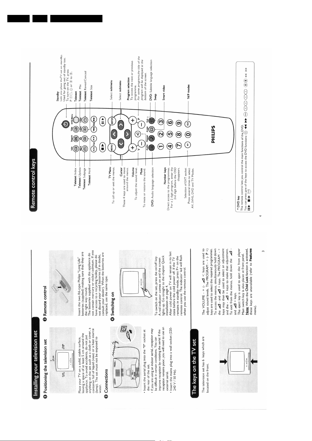
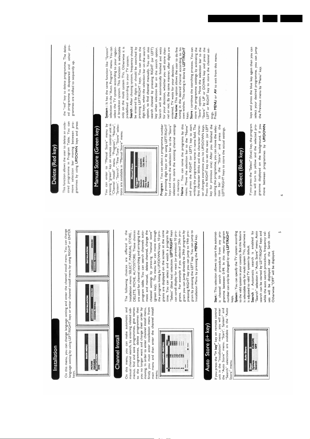
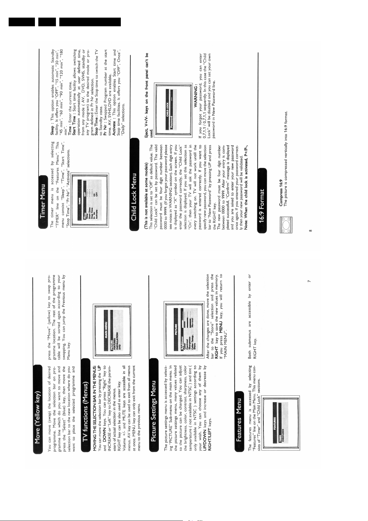
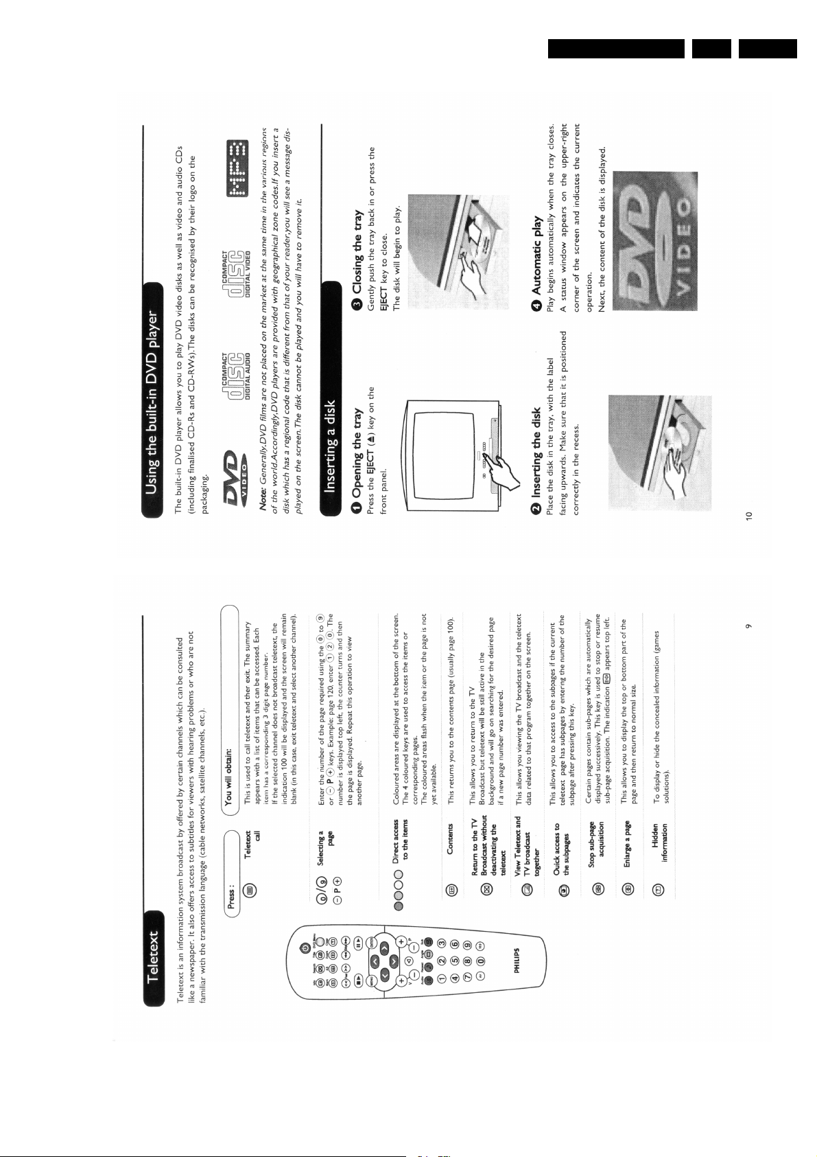
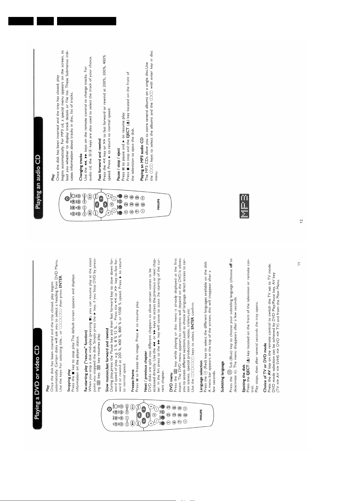
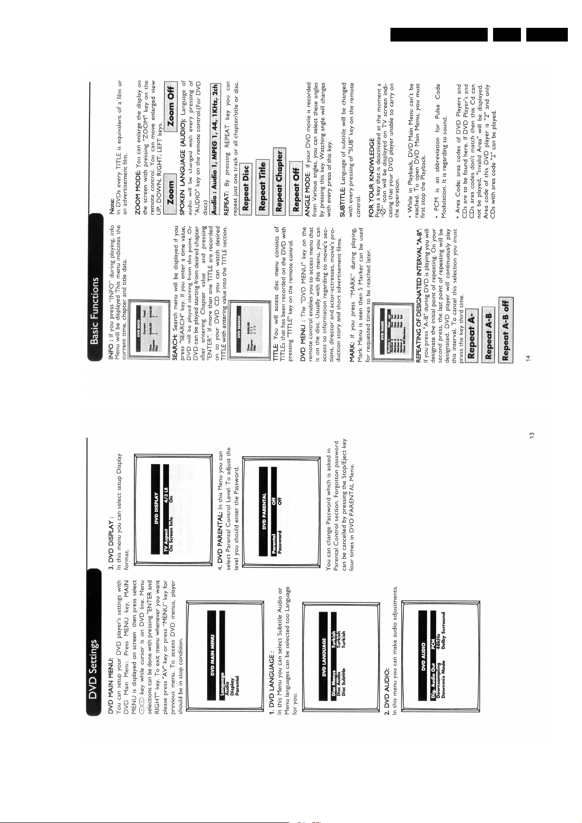
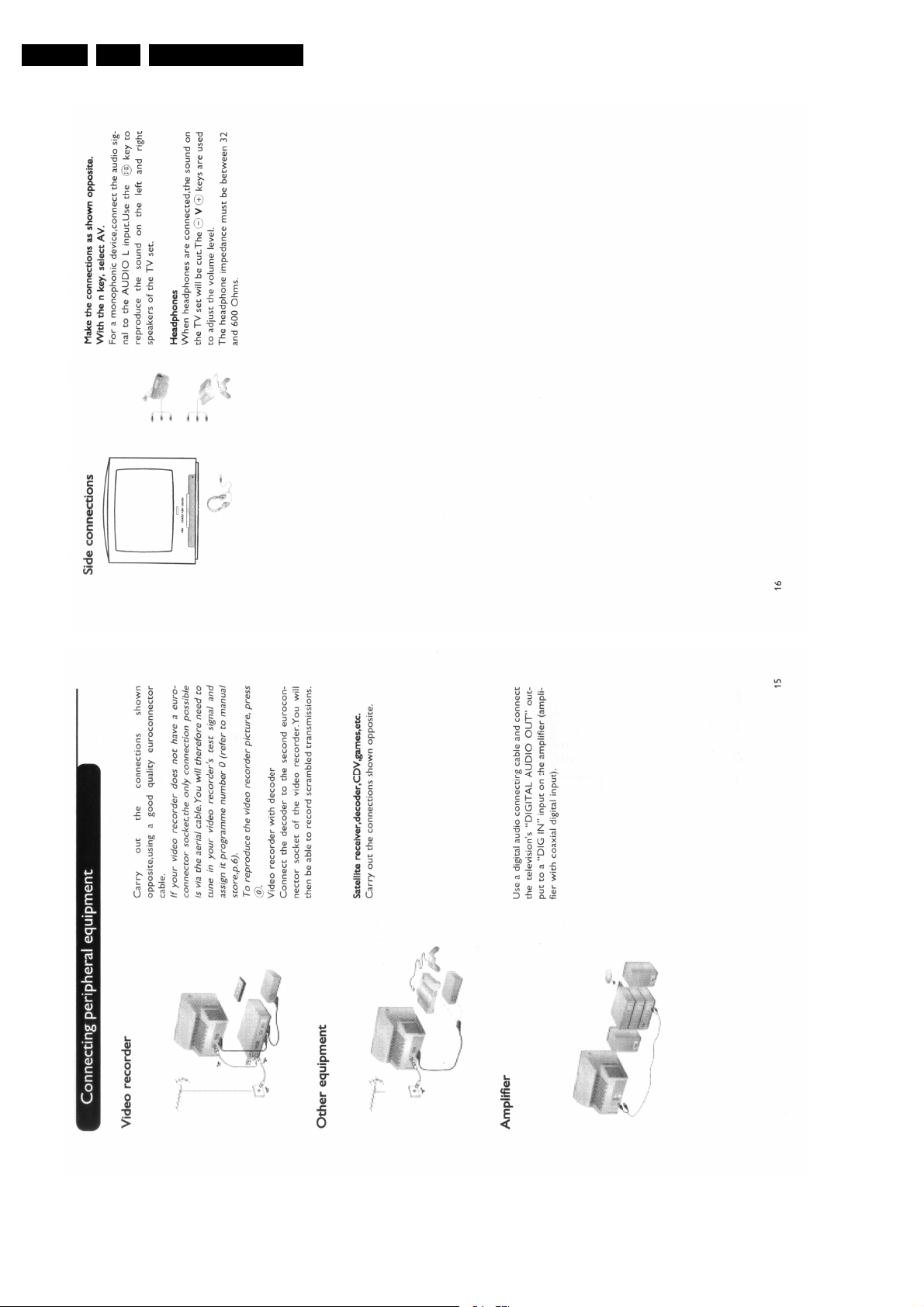
3. Directions for Use 6
4. Mechanical Instructions 14
5. Service Modes, Error Codes and Faultfinding 15
6. Block Diagram, I2C Bus Interconnection Diagram
and Supply Voltage Diagram
Block Diagram 17
2
I
C-Bus Interconnection Diagram 18
Supply Voltage Diagram 19
7. Electrical Diagrams and PWB’s Diagram CBA
Main Panel: Tuner (Diagram A1) 20 26-27
Main Panel: Video Processor (Diagram A2) 20 26-27
Main Panel: SCART (Diagram A3) 21 26-27
Main Panel: EEPROM (Diagram A4) 21 26-27
Main Panel: Power Supply (Diagram A5) 22 26-27
Main Panel: Horizontal (Diagram A6) 23 26-27
Main Panel: u-Controller (Diagram A7) 21 26-27
Main Panel: Audio Amplifier (Diagram A8) 24 26-27
Main Panel: Vertical (Diagram A9) 24 26-27
Main Panel: Out (Diagram A10)25 26-27
Main Panel: Keyboard Panel (Diagram A11)25 26-27
CRT Panel (Diagram B) 28 28
RC Panel (Diagram C) 29 29
Front AV Module (Diagram D) 29 29
Line Out Panel (Diagram E) 30 30
8. Alignments 31
9. Circuit Description 34
Abbreviation List (Not Applicable yet) 34
IC Data Sheets 34
10 Spare Parts List 42
©
Copyright 2002 Philips Consumer Electronics B.V. Eindhoven, The Netherlands.
All rights reserved. No part of this publication may be reproduced, stored in a
retrieval system or transmitted, in any form or by any means, electronic,
mechanical, photocopying, or otherwise without the prior permission of Philips.
Published by LM 0271 Service PaCE Printed in the Netherlands Subject to modification EN 3122 785 12970
EN 2 TDVD1.1E1.
Technical Specifications, Connection Facilities, and Chassis Overview
1. Technical Specifications, Connection Facilities, and Chassis Overview
1.1 Technical Specifications
1.1.1 Reception
Tuning System : PLL
Colour Systems : PAL
: SECAM
:NTSC
Sound System : Mono
A/V Connections : SCART
: FRONT AV
Channel Selections : Air
: Cable
IF Frequency : B/G, D/K, L: 38.9 MHz
: L': 33.4 MHz
: I: 39.5 MHz
Aerial Input : 75 Ohm
1.1.2 DVD module
Disc formats : CD (R/RW)
:CVD
: (S) VCD
:DVCD
:DVD (+R/+RW)
Rotational speed : 4x CD
:2x DVD
Data transfer rate : 2760 kB/s for DVD
: 688 kB/s for VCD
Avg. access time : 250 ms typical
Data buffer capacity : 512 Kbytes
1.1.3 Miscellaneous
Audio Output (RMS) : 2 x 2.5 W
Mains Voltage : 220 - 240 V (± 10 %)
Mains Frequency : 50 / 60 Hz (± 5 %)
Power Consumption : 50 W
Standby Power Consumption : 4 W
1.2 Connection/Control Facilities
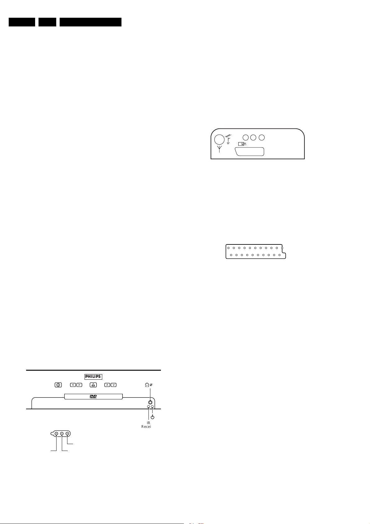
1.2.1 TV Side Connections and Front Control
FRONT CONTROL
PHILIPS
- VOLUME + - PROGRAM +
SIDE I/O
VIDEO
AUDIO R
AUDIO L
CL 26532120_001.eps
IR
Receiver
081102
3.5
Cinch (Input)
1 - CVBS 1 Vpp / 75 Ω
2 - Audio - L 0.5 Vrms / 10 kΩ
3 - Audio - R 0.5 Vrms / 10 kΩ
1.2.2 TV Rear Connections
REAR CONNECTIONS
PCMA/RA/L
EURO-AV
CL 26532120_002.eps
251002
Figure 1-2 Rear connections
Cinch (Output)
1 - Audio - L 0.5 Vrms / 1 kΩ
2 - Audio - R 0.5 Vrms / 1 kΩ
3 - S/PDIF (PCM)
Euro AV
121
CL96532137_056.eps
202
171199
Figure 1-3 SCART connector
1 - Audio - R 0.5 Vrms / 1 kOhm
2 - Audio - R 0.5 Vrms / 10 kOhm
3 - Audio - L 0.5 Vrms / 1 kOhm
4 - Audio Ground
5 - Blue Ground
6 - Audio - L 0.5 Vrms / 10 kOhm
7 - Blue 0.7 Vpp / 75 Ohm
8 - CVBS-status 0 - 1.3 V: INT
4.5 - 7 V: EXT 16:9
9.5 - 12 V: EXT 4:3
9 - Green Ground
10-
11-Green 0.7 Vpp / 75 Ohm
12-
13-Red Ground
14-CVBS status Ground
15-Red 0.7 Vpp / 75 Ohm
16-RGB status 0 - 0.4 V: INT
1 - 3 V: EXT / 75 Ohm
17-CVBS Ground
18-RGB status Ground
19-CVBS-o ut 1 Vpp / 75 Ohm
20-CVBS-in 1 Vpp / 75 Ohm
21-Shielding Ground
Figure 1-1 Side connections and Front control
Technical Specifications, Connection Facilities, and Chassis Overview
EN 3TDVD1.1E 1.
1.2.3 DVD Module Connections
DC Power Connector (CN401)
1 - Supply voltage + 12 V
2 - Ground
(analogue) A-GND
3 - Ground
(digital) D-GND
4 - Supply voltage + 5 V
A/V and DAIO Output (CN403)
1-ML n.c.
2-MC n.c.
3 - R/R (MD) Rear Right Audio
4 - AGND Audio Ground
5 - R/L (PCM2) Rear Left Audio
6 - CEN (PCM1) Centre Audio
7 - A-GND Audio Ground
8 - S/W (PCM0) Sub Woofer
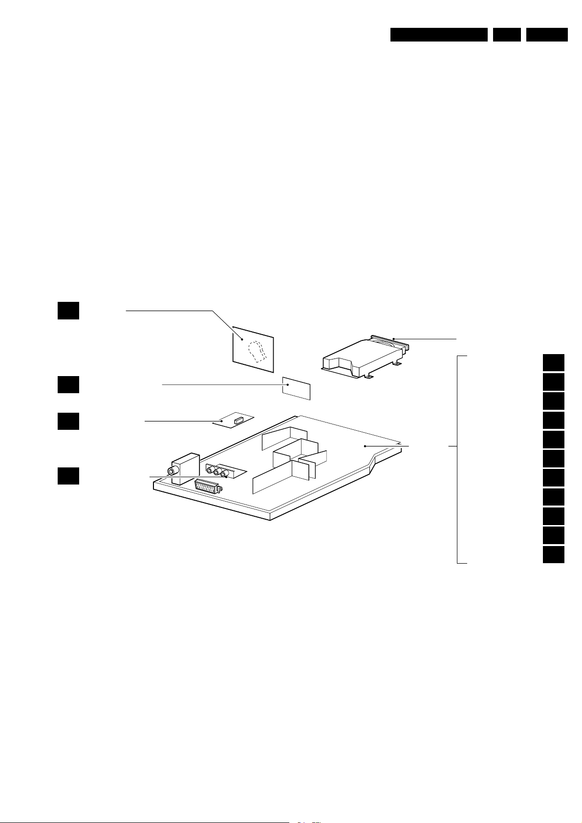
1.3 Chassis Overview
CRT PANEL
B
9 - F/R (SCK) Front Right Audio
10-A-GND Audio Ground
11-F/L (BCK) Front Left Audio
12-MUTE (LRCK) Mute for Audio
13-S/PDIF Digital Audio
14-D-GND Digital Ground
15-CVBS 1 Vpp / 75 Ohm
16-V-GND Video Ground
17-Y 1 Vpp / 75 Ohm
18-V-GND Video Ground
19-C 0.3 Vpp / 75 Ohm
20-V-GND Video Ground
21-G/Y 0.7 Vpp / 75 Ohm
22-B/Cb 0.7 Vpp / 75 Ohm
23-R/Cr 0.7 Vpp / 75 Ohm
24-V-GND Video Ground
25-VID_S/W Video switching
26-TV_S/W TV switching
DVD ENGINE
RC PANEL
C
FONT AV PANEL
D
LINE OUT PANEL
E
Figure 1-4 PWB location
MAIN
CHASSIS
PANEL
TUNER
VIDEO PROCESSOR
SCART
EEPROM
POWER SUPPLY
HORIZONTAL
µ-CONTROLLER
AUDIO AMPLIFIER
VERTICAL
AV INTERFACE CONN.
KEYBOARD
CL 26532120_003.eps
A1
A2
A3
A4
A5
A6
A7
A8
A9
A10
A11
061202
EN 4 TDVD1.1E2.
Safety and Maintenance Instructions, Warnings, and Notes
2. Safety and Maintenance Instructions, Warnings, and Notes
2.1 S af et y In st ruc tions
Safety regulations require that during a repair:
• Due to the chassis concept, a part of the circuitry is 'hot'.
Therefore, connect the set to the mains via an isolation
transformer.
• Replace safety components, indicated by the symbol
only by components identical to the original ones. Any
other component substitution (other than original type) may
increase risk of fire or electrical shock hazard.
• Wear safety goggles when you replace the CRT.
Safety regulations require that after a repair, you must return
the set in its original condition. Pay, in particular, attention to
the following points:
• General repair instruction: as a strict precaution, we advise
you to re-solder the solder connections through which the
horizontal deflection current is flowing. In particular this is
valid for the:
1. Pins of the line output transformer (LOT).
2. Fly-back capacitor(s).
3. S-correction capacitor(s).
4. Line output transistor.
5. Pins of the connector with wires to the deflection coil.
6. Other components through which the deflection current
flows.
Note: This re-soldering is advised to prevent bad connections
due to metal fatigue in solder connections, and is therefore only
necessary for television sets more than two years old.
• Route the wire trees and EHT cable correctly and secure
them with the mounted cable clamps.
• Check the insulation of the mains cord for external
damage.
• Check the strain relief of the mains cord for proper function,
to prevent the cord from touching the CRT, hot
components, or heat sinks.
• Check the electrical DC resistance between the mains plug
and the secondary side (only for sets that have an isolated
power supply). Do this as follows:
1. Unplug the mains cord and connect a wire between the
two pins of the mains plug.
2. Turn on the main power switch (keep the mains cord
unplugged!).
3. Measure the resistance value between the pins of the
mains plug and the metal shielding of the tuner or the
aerial connection of the set. The reading should be
between 4.5 MΩ and 12 MΩ.
4. Switch the TV 'off' and remove the wire between the
two pins of the mains plug.
• Check the cabinet for defects, to prevent the possibility of
the customer touching any internal parts.
,
Figure 2-1
Note: Use of controls or adjustments or performance of
procedure other than those specified herein, may result in
hazardous radiation exposure. Avoid direct exposure to beam.
2.2 Maintenance Instructions
We recommend a maintenance inspection carried out by
qualified service personnel. The interval depends on the usage
conditions:
• When a customer uses the set under normal
circumstances, for example in a living room, the
recommended interval is three to five years.
• When a customer uses the set in an environment with
higher dust, grease, or moisture levels, for example in a
kitchen, the recommended interval is one year.
• The maintenance inspection includes the following actions:
1. Perform the 'general repair instruction' noted above.
2. Clean the power supply and deflection circuitry on the
chassis.
3. Clean the picture tube panel and the neck of the picture
tube.
2.3 Warnings
2.3.1 General
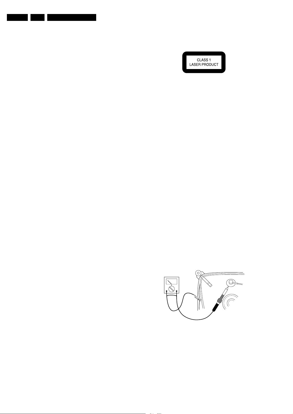
• In order to prevent damage to ICs and transistors, avoid all
high voltage flashovers. In order to prevent damage to the
picture tube, use the method shown in Fig. 2-2, to
discharge the picture tube. Use a high voltage probe and a
multi-meter (position V
reading is 0 V (after approx. 30 s).
V
). Discharge until the meter
DC
2.1.1 Laser Safety
This unit employs a laser. Only qualified service personnel may
remove the cover, or attempt to service this device (due to
possible eye injury).
Laser Device Unit
Type : Semiconductor laser
GaAlAs
Wavelength : 650 nm (DVD)
: 780 nm (VCD/CD)
Output Power : 20 mW (DVD+RW
writing)
: 0.8 mW (DVD
reading)
: 0.3 mW (VCD/CD
reading)
Beam divergence : 60 degree
CL96532156_040.eps
140501
Figure 2-2 Discharge picture tube
• All ICs and many other semiconductors are susceptible to
electrostatic discharges (ESD, symbol w). Careless
handling during repair can reduce life drastically. Make
sure that, during repair, you are connected with the same
potential as the mass of the set by a wristband with
resistance. Keep components and tools also at this
potential. Available ESD protection equipment:
– Complete kit ESD3 (small tablemat, wristband,
connection box, extension cable and ground cable)
4822 310 10671.
– Wristband tester 4822 344 13999.
Safety and Maintenance Instructions, Warnings, and Notes
• Together with the deflection unit and any multi-pole unit,
flat square picture tubes form an integrated unit. The
deflection and the multi-pole units are set optimally at the
factory. We do not recommend adjusting this unit during
repair.
• Be careful during measurements in the high voltage
section and on the picture tube.
• Never replace modules or other components while the unit
is 'on’.
• When you align the set, use plastic rather than metal tools.
This will prevent any short circuits and the danger of a
circuit becoming unstable.
2.3.2 Laser
• The use of optical instruments with this product, will
increase eye hazard.
• Only qualified service personnel may remove the cover or
attempt to service this device, due to possible eye injury.
• Repair handling should take place as much as possible
with a disc loaded inside the player.
• Text below is placed inside the unit, on the laser cover
shield:
CAUTION VISIBLE AND INVISIBLE LASER RADIATION WHEN OPEN AVOID EXPOSURE TO BEAM
ADVARSEL SYNLIG OG USYNLIG LASERSTRÅLING VED ÅBNING UNDGÅ UDSÆTTELSE FOR STRÅLING
ADVARSEL SYNLIG OG USYNLIG LASERSTRÅLING NÅR DEKSEL ÅPNES UNNGÅ EKSPONERING FOR STRÅLEN
VARNING SYNLIG OCH OSYNLIG LASERSTRÅLNING NÄR DENNA DEL ÄR ÖPPNAD BETRAKTA EJ STRÅLEN
VARO! AVATT AESSA OLET ALTTIINA NÄKYVÄLLE JA NÄKYMÄTTÖMÄLLE LASER SÄTEILYLLE. ÄLÄ KATSO SÄTEESEEN
VORSICHT SICHTBARE UND UNSICHTBARE LASERSTRAHLUNG WENN ABDECKUNG GEÖFFNET NICHT DEM STRAHL AUSSETSEN
DANGER VISIBLE AND INVISIBLE LASER RADIATION WHEN OPEN AVOID DIRECT EXPOSURE TO BEAM
ATTENTION RAYO NNEMENT LASER VISIBLE ET INVISIBLE EN CAS D'OUVERTURE EXPOSITION DANGEREUSE AU FAISCEAU
!
EN 5TDVD1.1E 2.
Figure 2-3
2.4 Notes
• Measure the voltages and waveforms with regard to the
chassis (= tuner) ground (), or hot ground (), depending
on the tested area of circuitry.
• The voltages and waveforms shown in the diagrams are
indicative. Measure them in the Service Default Mode (see
chapter 5) with a colour bar signal and stereo sound (L: 3
kHz, R: 1 kHz unless stated otherwise) and picture carrier
at 475.25 MHz (PAL) or 61.25 MHz (NTSC, channel 3).
• Where necessary, measure the waveforms and voltages
with () and without () aerial signal. Measure the
voltages in the power supply section both in normal
operation () and in standby (). These values are
indicated by means of the appropriate symbols.
• The picture tube panel has printed spark gaps. Each spark
gap is connected between an electrode of the picture tube
and the Aquadag coating.
• The semiconductors indicated in the circuit diagram and in
the parts lists, are interchangeable per position with the
semiconductors in the unit, irrespective of the type
indication on these semiconductors.
EN 6 TDVD1.1E3.
3. Directions for Use
Directions for Use
Directions for Use
EN 7TDVD1.1E 3.
EN 8 TDVD1.1E3.
Directions for Use
Directions for Use
EN 9TDVD1.1E 3.
EN 10 TDVD1.1E3.
Directions for Use
Directions for Use
EN 11TDVD1.1E 3.
EN 12 TDVD1.1E3.
Directions for Use
Directions for Use
EN 13TDVD1.1E 3.
Personal Notes:
EN 14 TDVD1.1E4.
Mechanical instructions
4. Mechanical instructions
Index of this chapter:
1. Rear Cover Removal
2. Service Position Main Panel
3. DVD Module Removal
4. Side I/O Panel Removal
5. Rear I/O Panel Removal
6. Rear Cover Mounting
Note:
Figures can deviate slightly from the actual situation.
4.1 Rear Cover Removal
1. Remove all fixation screws (7x) of the rear cover.
2. Pull the rear cover a little backwards.
3. Disconnect the Rear I/O and Side I/O panel cables
4. Now pull the rear cover backwards to remove it.
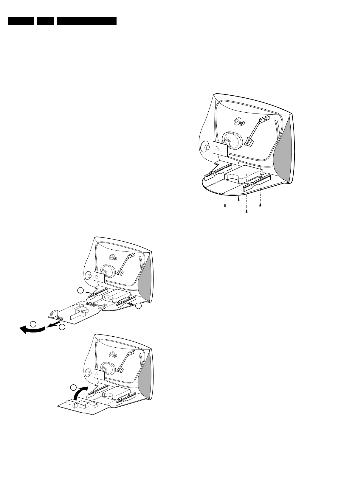
4.2 Service Position Main Panel
1. Disconnect all cables of the DVD module.
2. Remove the main panel, by pushing the two centre clips
outward [1]. At the same time, pull the panel away from the
CRT [2].
3. Turn the panel 90 degrees clockwise [3].
4. Flip the panel 90 degrees [4], with the components towards
the CRT.
4.3 DVD Module Removal
Remove the complete DVD module after unscrewing the four
fixation screws [1].
CL 26532120_026.eps
Figure 4-2 Disassemble DVD module
311002
4.4 Side I/O Panel Removal
A
Remove the side I/O panel after unscrewing the screw from the
outside of the rear cover.
4.5 Rear I/O Panel Removal
1
1
Remove the rear I/O panel after unscrewing the two screws
from the inside of the rear cover.
4.6 Rear Cover Mounting
3
2
B
To reassemble the set, perform all described processes in
reverse order.
Be sure that, before the rear cover is mounted:
• The mains cord is mounted correctly in its guiding bracket.
• All wires/cables are returned in their original position.
4
CL 26532120_027.eps
311002
Figure 4-1 Service position Main panel
 Loading...