


INTEGRATED CIRCUITS
DATA SH EET
TDA5147CH
12 V Voice Coil Motor (VCM) driver
and spindle motor drive
combination chip
Preliminary specification
File under Integrated Circuits, IC11
1997 Jul 09

Philips Semiconductors Preliminary specification
12 V Voice Coil Motor (VCM) driver and
spindle motor drive combination chip
FEATURES
Spindle motor driver
• Internal 2 A peak current power drivers
• Low R
isolation drivers
• Induction sense start-up option
• External current sense resistor
• Soft switching on both upper and lower drivers
• Programmable linear or Pulse Width Modulation (PWM)
spindle mode
• Provide spindle active dynamic braking mode.
Voice coil motor driver
• 1.2 A VCM power driver
• Maximum of 1 V drop across the power driver at 0.8 A
• External current sense resistor, with sense amplifier
• External current control loop compensation
• 15 kHz (typ.) VCM current control loop bandwidth
• Three modes of operation:
– Enable VCM
– Retract
– Disable
• Brake after park circuitry.
Power monitor and retract circuit
• +5 V and +12 V power monitor threshold accuracy ±2%
• Hysteresis on both power monitor comparators
• Internal voltage reference: precision 2%
• Buffered reference voltage output pin
(1 Ω maximum total) for high, low and
ds(on)
TDA5147CH
• Retract circuit operates down to 2 V
• Internal thermal sense circuitry with an over temperature
shut down option
• Internal boost voltage generator
• Sleep mode.
Thermal warning circuit
• Output active 15 °C before general thermal shutdown.
APPLICATIONS
• Hard disk drive for Personal Computer products.
GENERAL DESCRIPTION
The TDA5147CH is an ASIC combination chip that
includes the following functions:
spindle motor driver
voice coil motor driver
retract
Power-on.
The circuit is contained in a 64-pin QFP package.
The TDA5147CH is controlled by a custom digital ASIC
(see Chapter “Application Information”). The custom ASIC
provides the necessary commutation sequences for the
spindle drivers via the SCNTL1, SCNTL2 and SCNTL3
inputs. Spindle speed is monitored by comparator outputs
SENU, SENV and SENWIS. Motor speed control is
accomplished by a PWM signal (input at pin SIPWM).
Control of the VCM circuits is via the V
input signals. These inputs provide control of the voice coil
current.
IPWMH
and V
IPWML
ORDERING INFORMATION
TYPE
NUMBER
TDA5147CH QFP64 plastic quad flat package; 64 leads (lead length 1.6 mm);
1997 Jul 09 2
NAME DESCRIPTION VERSION
body 14 × 14 × 2.7 mm
PACKAGE
SOT393-1
Philips Semiconductors Preliminary specification
12 V Voice Coil Motor (VCM) driver and
TDA5147CH
spindle motor drive combination chip
QUICK REFERENCE DATA
SYMBOL PARAMETER MIN. TYP. MAX. UNIT
Supply voltage
V
CC5
V
CCA12
V
CCS12
V
CC1V12
V
CC2V12
Drivers
I
spin(max)
I
VCM(max)
analog supply voltage 1 4.5 5.0 5.5 V
analog supply voltage 2 10.8 12 13.2 V
power supply for spindle motor drivers 10.8 12 13.2 V
power supply 1 for VCM driver 10.8 12 13.2 V
power supply 2 for VCM driver 10.8 12 13.2 V
maximum spindle current − 2 − A
maximum VCM current − 1.2 − A
1997 Jul 09 3
Philips Semiconductors Preliminary specification
12 V Voice Coil Motor (VCM) driver and
spindle motor drive combination chip
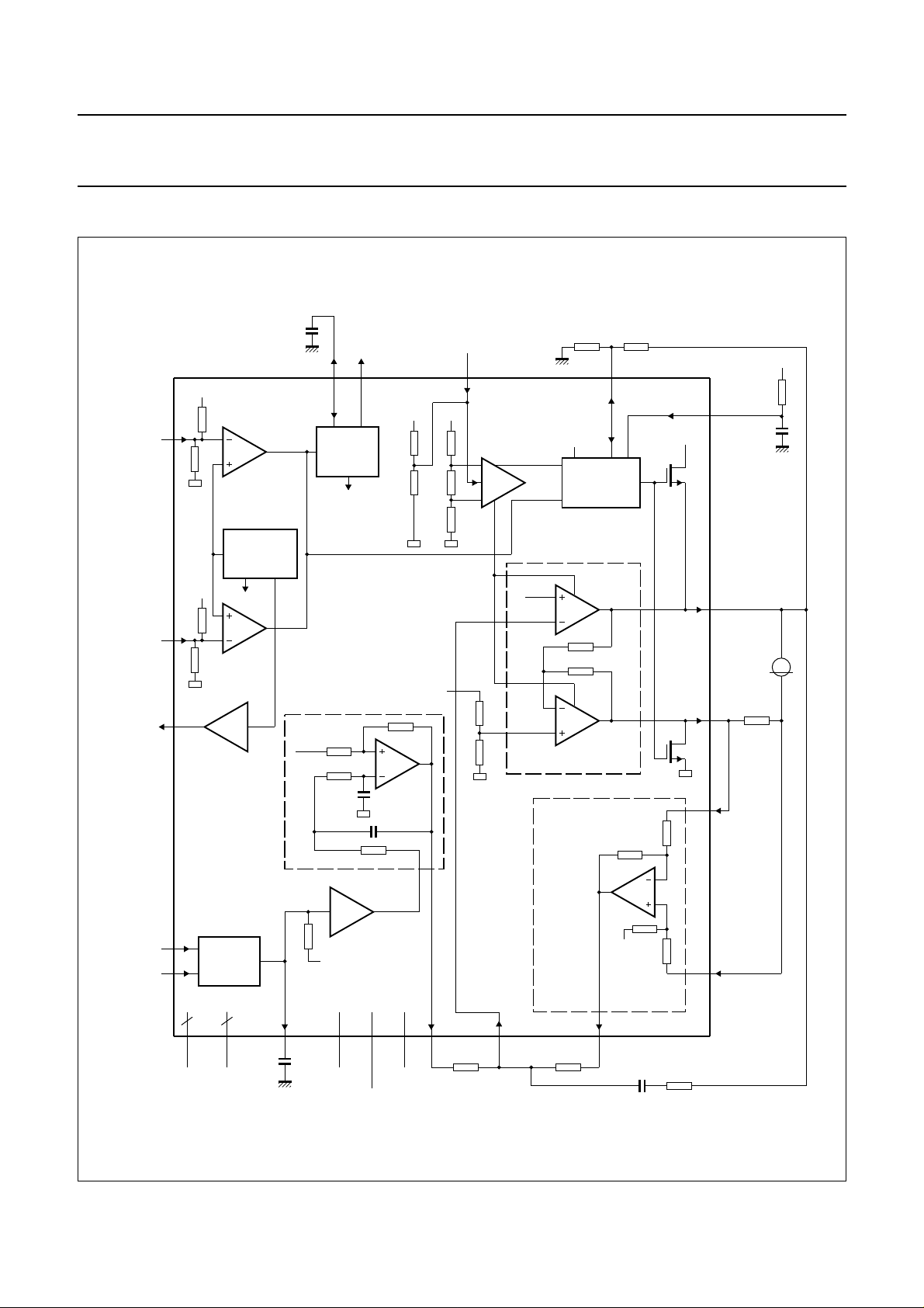
BLOCK DIAGRAMS
handbook, full pagewidth
PORNCPOR
14
POR12
VADJ
16
V
V
CCA12
CC5
UNDER
VOLTAGE
GENERATOR
V
ref
POR
DETECTOR
to spindle
section
15
V
DD
V
DD
disable
V
PCNTL
50
park
autopark
V
refout
SHPWR1
PARK
CIRCUITRY
RET
35
ADJ
SHPWR2,3
TDA5147CH
SHPWRZ
BRKTC
53
59
V
CMN
POR5
V
V
VADJ
V
refout
IPWML
IPWMH
17
52
1
PWM
2
DECODER
GNDSUBB GNDV
V
refout
3644996, 7 54, 55, 56
V
FLTINP
TDA5147CH
V
refout
V
CC1V12
V
CC2V12
V
V
CCA12
CC5
V
FLTOUT
POWER AMPLIFIERS
SENSE
474
V
CMINP
61
V
V
refout
ISENS1
51VCMP
60
V
ISENL
57VISENH
M
R
s
MGG845
Fig.1 Block diagram of voice coil motor driver.
1997 Jul 09 4
Philips Semiconductors Preliminary specification
12 V Voice Coil Motor (VCM) driver and
spindle motor drive combination chip
handbook, full pagewidth
BSTFLT
SCNTL2
SCNTL3
29
20SCNTL1
21
22
13SMODE1
V
CC5
41 30
UPPER
BOOSTER
LOGIC
DECODER
V
CC5
V
CC5
BSTCP2BSTCP1
to the VCM
output
stages
U.H
U.L
V.H
THERMAL
V.L
SWITCH
W.H
W.L
brake
disable
TDA5147CH
l
compare
TEMP
SPWMTC
2458
PWM/LIN
PWM
U.H
U.L
V.H
V.L
DRIVER
DRIVER
DRIVER
DRIVER
disable
disable
brake
disable
disable
brake
from PORN block
V
CCS12
TDA5147CH
28
SHPWR3
5
SHPWR2
39
SDRVU
40
SHPWR1
C
clamp
23
SDRVV
R
sense
SISENL 46
SISENH 45
37SCOMP
44SIPWM
38SPWMFLT
PWM
DECODER
FILTER
AMP
19
SISINK242SISINK1
V
ref
I
sense
COMP
PWM/LIN
I
set
I
sense
COMP
I
set
I
compare
6, 7
GNDSUBB
control
amplifier
36
V
CCS12
W.H
W.L
multiplexer
8
V
CCA12
DRIVER
DRIVER
9
V
CC5
disable
disable
brake
SISINK1, SISINK2
COMP
SDRVU
COMP
SDRVV
COMP
SDRVW
54, 55, 56
GNDV
10
25
27
26
18
SDRVW
SDRVN
SENV
SENU
SENWIS
MGG844
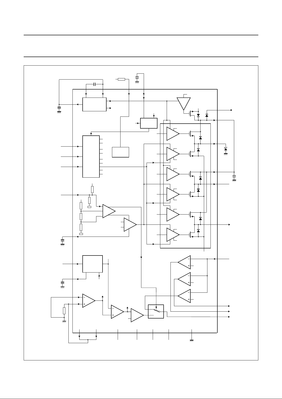
Fig.2 Block diagram of spindle motor drivers.
1997 Jul 09 5

Philips Semiconductors Preliminary specification
12 V Voice Coil Motor (VCM) driver and
spindle motor drive combination chip
PINNING
SYMBOL PIN I/O DESCRIPTION
V
IPWML
V
IPWMH
V
FLTINP
V
FLTOUT
SHPWR2 5 O capacitor for park supply
GNDSUBB 6 − analog ground 2
GNDSUBB 7 − analog ground 2
V
CCA12
V
CC5
SDRVW 10 O phase 3 output for spindle
n.c. 11 − not connected
n.c. 12 − not connected
SMODE1 13 − 3 level input for spindle
CPOR 14 I/O Power-on reset delay
PORN 15 O Power-on reset digital output
POR12
POR5
VADJ
VADJ
SENWIS 18 O digital output of back EMF
SISINK2 19 O connection 2 to the sense
SCNTL1 20 I digital input 1 for spindle
SCNTL2 21 I digital input 2 for spindle
SCNTL3 22 I digital input 3 for spindle
SDRVV 23 O phase 2 output for spindle
SPWMTC 24 I/O capacitor for spindle low side
SDRVN 25 O centre TAP connection to
SENU 26 O digital output of back EMF
1 I LSB PWM input
2 I MSB PWM input
3 O voice coil motor PWM filter
capacitor
4 O PWM filter output voltage
voltage
8 − analog supply voltage 2
(+12 V)
9 − analog supply voltage 1
(+5 V)
motor
mode
capacitor
(active LOW)
16 I adjustment of PORN
threshold (for +12 V)
17 I adjustment of PORN
threshold (for +5 V)
sense 3/inductive sense
resistor
decoder
decoder
decoder
motor
PWM time off
spindle motor
sense 1
TDA5147CH
SYMBOL PIN I/O DESCRIPTION
SENV 27 O digital output of back EMF
sense 2
SHPWR3 28 O capacitor 3 for park supply
voltage
BSTFLT 29 O booster filter output
BSTCP2 30 O booster capacitor 2 output
n.c. 31 − not connected
n.c. 32 − not connected
n.c. 33 − not connected
n.c. 34 − not connected
RET
ADJ
V
CCS12
SCOMP 37 O control amplifier pole
SPWMFLT 38 I/O capacitor for spindle PWM
SDRVU 39 O phase 1 output for spindle
SHPWR1 40 O capacitor 1 for park supply
BSTCP1 41 O booster capacitor 1 output
SISINK1 42 O connection 1 to the sense
GNDSUBA 43 − analog ground 1
SIPWM 44 I digital PWM input for spindle
SISENH 45 I sense resistor for spindle
SISENL 46 I isolated ground connection
V
CMINP
n.c. 48 − not connected
V
CC2V12
V
PCNTL
V
CMP
V
refout
BRKTC 53 I input for setting brake after
35 I/O retract voltage adjustment
pin
36 − power supply of spindle
motor drivers (+12 V)
adjustment
filter
motor
voltage
resistor
current
current
for spindle sense amplifier
47 I closed loop voltage
compensation of VCM
49 − +12 V power supply of VCM
driver
50 I park enable 3-level input
51 O positive output voltage of
H-Bridge
52 O output reference for external
ADC
park time
1997 Jul 09 6

Philips Semiconductors Preliminary specification
12 V Voice Coil Motor (VCM) driver and
spindle motor drive combination chip
SYMBOL PIN I/O DESCRIPTION
GNDV 54 − power ground 2 of voice coil
motor driver
GNDV 55 − power ground 2 of voice coil
motor driver
GNDV 56 − power ground 2 of voice coil
motor driver
V
ISENH
TEMP 58 O open collector output for
handbook, full pagewidth
57 I positive input voltage of
sense resistor amplifier
early thermal warning
CC1V12
V
64
n.c.
63
ISENS1VISENLVCMN
n.c.
V
62
61
60
TEMP
59
58
TDA5147CH
SYMBOL PIN I/O DESCRIPTION
V
CMN
V
ISENL
V
ISENS1
n.c. 62 − not connected
n.c. 63 − not connected
V
CC1V12
ISENH
V
GNDV
GNDV
GNDV
57
56
55
54
59 O negative output voltage of
H-Bridge
60 I negative input voltage of
sense resistor amplifier
61 O voltage output 1 of sense
resistor amplifier
64 − +12 V power supply of VCM
driver
refoutVCMPVPCNTLVCC2V12
BRKTC
V
53
52
51
50
V
IPWML
V
IPWMH
V
FLTINP
V
FLTOUT
SHPWR2
GNDSUBB
GNDSUBB
V
CCA12
SDRVW
SMODE1
CPOR
PORN
POR12
V
CC5
n.c.
n.c.
VADJ
1
2
3
4
5
6
7
8
9
10
11
12
13
14
15
16
17
VADJ
POR5
18
SENWIS
20
19
SISINK2
SCNTL1
21
22
SCNTL2
SCNTL3
TDA5147CH
23
24
25
SDRVV
SDRVN
SPWMTC
26
SENU
27
SENV
28
29
BSTFLT
SHPWR3
30
31
n.c.
BSTCP2
48
n.c.
V
47
CMINP
SISENL
46
SISENH
45
SIPWM
44
GNDSUBA
43
SISINK1
42
BSTCP1
41
SHPWR1
40
SDRVU
39
SPWMFLT
38
SCOMP
37
V
36
CCS12
RET
35
ADJ
n.c.
34
33
n.c.
32
MGG842
n.c. 49
Fig.3 Pin configuration.
1997 Jul 09 7

Philips Semiconductors Preliminary specification
12 V Voice Coil Motor (VCM) driver and
spindle motor drive combination chip
FUNCTIONAL DESCRIPTION
Spindle drivers
The spindle section (see Fig.2) contains both the low and
high side drivers (configured as H bridges) for a
three-phase DC brushless motor. Back EMF (Electro
Motive Force) sensing of the commutation rate
(pin SENWIS) is an output to an external digital ASIC
circuit. This circuit should provide the input commutation
control as well. Consequently, all speed control, start-up
routine and commutation control will be generated by the
external digital circuit.
The SIPWM signal from the digital circuit is used to control
the spindle current. This PWM signal is internally filtered.
The output of this filter depends solely on the duty factor.
The pole location of this first order low-pass filter is
controlled by an external capacitor at pin SPWMFLT.
Dynamic braking is possible only during non power-down
situations and must be initiated by the digital circuit.
A 3- level mode line (pin SMODE1) allows for:
• Induction sensing in pre-start-up (SMODE1 = 0.5V
or high impedance)
• PWM control during start-up (SMODE1 = 0 V)
• Linear control (SMODE1 = V
CC5
).
CC5
TDA5147CH
mode is to drive the low drivers into saturation, because
saturation reduces the power dissipation during start-up.
When the spindle current reaches the value destined by
the duty factor of the signal at pin SIPWM, a one-shot is
fired. The output of the one-shot remains HIGH for the
programmed off-time (t
pin SPWMTC. The one-shot is not retriggerable for
approximately 10% of the off-time, giving a minimum for
the on-time of 0.1t
output drivers are switched off. The on-time of the drivers
is determined by the charging time of the coil current.
The turn-off time follows: t
With R = 68 kΩ and C = 220 pF, t
The minimum on-time is:
INEAR MODE
L
The linear mode is used when the motor is near to its
intended speed. It can also be used at start-up, but higher
power dissipation will occur. In the linear mode the drivers
are controlled by a sensing amplifier. A Miller network is
used to obtain soft switching on the lower drivers. This
prevents large voltage spikes on the motor coils when the
lower drivers are switching. The high drivers are switched
into the linear (resistive) region.
) set by the RC-network at
off
. During the off-time, the lower spindle
off
=R×C
off
t
=
on
CV
-------I
off
ln(2)
= 10.4 µs
S
ENSING MODE
The induction sensing mode can be used to sense the
rotor position and to spin-up with high current.
To sense the rotor position, one of the BEMF sensor
outputs (pin SENWIS) will be shared with the voltage
comparator that is used for the induction sensing function.
Prior to start-up each phase is excited for a short period of
time. The current from each coil can be monitored via the
multiplexed output (SENWIS). By comparing the rise times
of each phase the rotor position can be determined.
In cases where the spindle motor requires more current to
spin-up, the sensing mode is used with the exception that
the output SENWIS is ignored. The output drivers are
operated in saturation in the sensing mode, so the motor
current is only limited by the power supply. This condition
of induction sense mode can be used to overcome the
head friction and must only be used when needed.
PWM M
ODE
The PWM mode is normally used during the start-up
phase. Maximum drive voltage is applied to the low drivers
to obtain high start-up torque. The purpose of the PWM
The transconductance gain of the low driver current to filter
voltage can be calculated as follows:
G
m
I
coil
--------------------------- V
SPWMFLT
V
1
SISENH
------
--------------------------- V
R
s
SPWMFLT
1
1
-----R
s
A/V=====
-- 5
For a 100% duty factor at SIPWM, the nominal voltage at
SPWMFLT = 1.74 V. The calculated coil current for a
100% duty factor (sense resistors R
1
1
I
coil
-----------
0.33
1.74 1.05 A=××=
-- 5
= 0.33 Ω) is:
s
Referencing to the duty factor, the coil current is:
I
coil
-----R
1
1
-- 5
s
1.74
0% duty
××
--------------------100
1
0.348()
-----R
s
0% duty
×===
--------------------100
The duty factor is arranged so that at 100%, the voltage
SPWMFLT = 1.74 V and at a 5% duty factor
SPWMFLT = 0 V. This is to ensure that at 0% duty factor
the current will be zero (allowances for circuit tolerances).
The input decoder is driven by three lines which define the
windings to be energized. The input decoder must then
translate these lines to six lines to drive the six output
drivers. The truth table is given in Table 1. The status of
each block in the spindle drive section during the possible
modes of operation is given in Table 4
1997 Jul 09 8

Philips Semiconductors Preliminary specification
12 V Voice Coil Motor (VCM) driver and
TDA5147CH
spindle motor drive combination chip
Table 1 Input decoder truth table for spindle motor drivers
CONDITION SCNTL1 SCNTL2 SCNTL3 SDRVU
(1)
SDRVV
Disable LOW LOW LOW x x x
Dynamic brake HIGH HIGH HIGH HIGH HIGH HIGH
State 1 HIGH HIGH LOW LOW x HIGH
State 2 HIGH LOW LOW x LOW HIGH
State 3 HIGH LOW HIGH HIGH LOW x
State 4 LOW LOW HIGH HIGH x LOW
State 5 LOW HIGH HIGH x HIGH LOW
State 6 LOW HIGH LOW LOW HIGH x
Under voltage −−−xxx
Note
1. x = high impedance.
VCM driver
The VCM driver (see Fig.1) is a linear, class AB, H-bridge
type power driver with all power devices internal to the IC.
In addition to the power stage a sense resistor enables the
VCM current to be measured. The VCM current is
controlled (see Fig.5) via two PWM signals, V
V
, that are generated by the digital circuit. The signal
IPWML
at pin V
pin V
IPWML
factor of (V
weights 32 times more than the signal at
IPWMH
, thus the current is proportional to the duty
IPWML
+32×V
). These PWM signals are
IPWMH
IPWMH
and
filtered by using an internal 3rd-order low-pass filter
(Butterworth filter).The bandwidth of this low-pass filter is
nominally 40 kHz (less than 2 degrees lag at 500 Hz), but
the real pole may be adjusted by an external capacitor
connected to pin V
. The filter output (pin V
FLTINP
depends on the duty factor of the PWM signals only.
A 3-level mode line (V
• Enable VCM drivers; V
• Disable VCM drivers; V
) has been included that will:
PCNTL
PCNTL=VCC5
= 0.5V
PCNTL
impedance
• Park (soft retract the actuator); V
See Table 2 for the truth table of the VCM driver modes.
(normal)
CC5
PCNTL
(1)
or high
=0V.
SDRVW
FLTOUT
(1)
)
Table 2 V
MODES OF OPERATION AT
POWER GOOD (PORN = HIGH)
VCM enable V
VCM disable 0.5V
and SCNTL modes
PCNTL
V
INPUT STATE
PCNTL
CC5
or high impedance X X X
CC5
(1)
SCNTL1 SCNTL2 SCNTL3
SCNTL INPUT STATES
XXX
(1)
Park 0 V X X X
Spindle enable X see Table 3 see Table 3 see Table 3
Spindle disable X LOW LOW LOW
Spindle brake X HIGH HIGH HIGH
Spindle mode 0.5V
or high impedance LOW LOW LOW
CC5
Note
1. X = don't care.
1997 Jul 09 9

Philips Semiconductors Preliminary specification
12 V Voice Coil Motor (VCM) driver and
spindle motor drive combination chip
ENABLE VCM DRIVERS
When V
by V
IPWMH
voltage at pin V
voltage is approximately 1 V above V
factor the V
V
. At a 50% duty factor, the voltage level is equal to
refout
V
(typically 4 V). The V
refout
filtered and output at V
varies between ±2 V about V
conjunction with the sense resistor amplifier, drives the
two VCM drivers as illustrated in Fig.4. The equation
describing the transconductance from V
handbook, full pagewidth
PCNTL
and V
equals V
IPWML
FLTOUT
voltage is approximately 1 V below
FLTINP
, the VCM drivers are controlled
CC5
. Their duty factor is converted to a
. At a 100% duty factor the V
refout
voltage is amplified,
FLTINP
. The voltage at V
FLTOUT
. The V
refout
. At a 0% duty
FLTOUT
voltage, in
FLTOUT
to I
FLTINP
coil
FLTINP
is:
TDA5147CH
I
G
=
--------------------------------------------
m
V
=
----------------------------------------------------V
VFLTOUTVrefout
2
=
In a typical application:
I
-------------------------------------------V
coil
FLTINPVrefout
The transconductance is variable by selecting external
resistors R2/R1 and sense resistors RS.
V
refout
coil
2I
–
coil
VFLTINPVrefout
–()
1
R2
---------- -
------- -
gain
R1
2
–
-- 4
1
-------RS
×
A/V×××
6.6 kΩ
-----------------10 kΩ
× 1 A/V==
1
-----------
0.33
R2
V
IPWML
V
IPWMH
V
FLTINP
V
CMINP
V
ISENS1
1
2
3
V
45
61
refout
PWM
DEC
4R
V1
V1
0.5 V
4R
BUFFER
R1
R
CCV12
V
refout
R
R
R
R
V
FLTOUT
4
V
CMN
59
R
V
CMP
51
V
ISENL
60
V
ISENH
57
I
COIL
RS
MGG846
voice
M
coil
motor
Fig.4 Transconductance model.
1997 Jul 09 10
 Loading...