

Philips tda4580 DATASHEETS

INTEGRATED CIRCUITS
DATA SH EET
TDA4580
Video control combination circuit
with automatic cut-off control
Product specification
File under Integrated Circuits, IC02
March 1991

Philips Semiconductors Product specification
Video control combination circuit with
automatic cut-off control
GENERAL DESCRIPTION
The TDA4580 is a monolithic integrated circuit which
performs video control functions in television receivers
with a colour difference interface. For example it operates
in conjunction the multistandard colour decoder TDA4555.
The required input signals are: luminance and negative
colour difference −(R-Y) and −(B-Y), and a 3-level
sandcastle pulse for control purposes. Analogue RGB
signals can be inserted from two sources. One with full
performance adjustment possibilities. RGB output signals
are available for driving the video output stages. This
circuit provides automatic cut-off control of the picture
tube.
Features
• Capacitive coupling of the colour difference, luminance
and RGB input signals with black level clamping
• Two sets of analogue RGB inputs via fast switch 1 and
fast switch 2
• First RGB inputs and fast switch 1 in accordance with
peritelevision connector specification
• Saturation, contrast and brightness control acting on
first RGB inputs
TDA4580
• Brightness control acting on second RGB inputs
• Equal black levels for television and inserted signals
• Clamping, horizontal and vertical blanking, and timing of
automatic cut-off, controlled by a 3-level sandcastle
pulse
• Automatic cut-off control with compensation for leakage
current of the picture tube
• Measuring pulses of cut-off control start immediately
after end of vertical part of sandcastle pulse
• Three selectable blanking intervals for PAL, SECAM
and NTSC/PAL-M
• Two switch-on delays for run-in without discolouration
• Adjustable peak drive limiter
• Average beam current limiter
• G-Y and RGB matrix coefficients selectable for
PAL/SECAM and NTSC (correction for FCC primaries)
• Bandwidth 10 MHz (typ.)
• Emitter-follower outputs for driving the RGB output
stages
QUICK REFERENCE DATA
Supply voltage (pin 6) V
Supply current (pin 6) I
Luminance input (pin 15)
Composite video input signal (VBS)
(peak-to-peak value) V
Colour difference input signals
(peak-to-peak values)
−(B-Y) V
−(R-Y) V
Inserted RGB signals
(black to white values) V
Inserted RGB signals for teletext use
(black to white values) V
Three-level sandcastle pulse
(required input voltage) V
PACKAGE OUTLINE
28-lead DIL; plastic (SOT117); SOT117-1; 1996 November 28.
= V
P
6-24
= I
P
6
15-24(p-p)
18-24(p-p)
17-24(p-p)
14, 13, 12-24
23, 22, 21-24
10-24
typ. 12 V
typ. 110 mA
typ. 0,45 V
typ. 1,33 V
typ. 1,05 V
typ. 0,7 V
typ. 1 V
typ. 2,5/4,5/8,0 V
March 1991 2

Philips Semiconductors Product specification
Video control combination circuit with
automatic cut-off control
TDA4580
March 1991 3
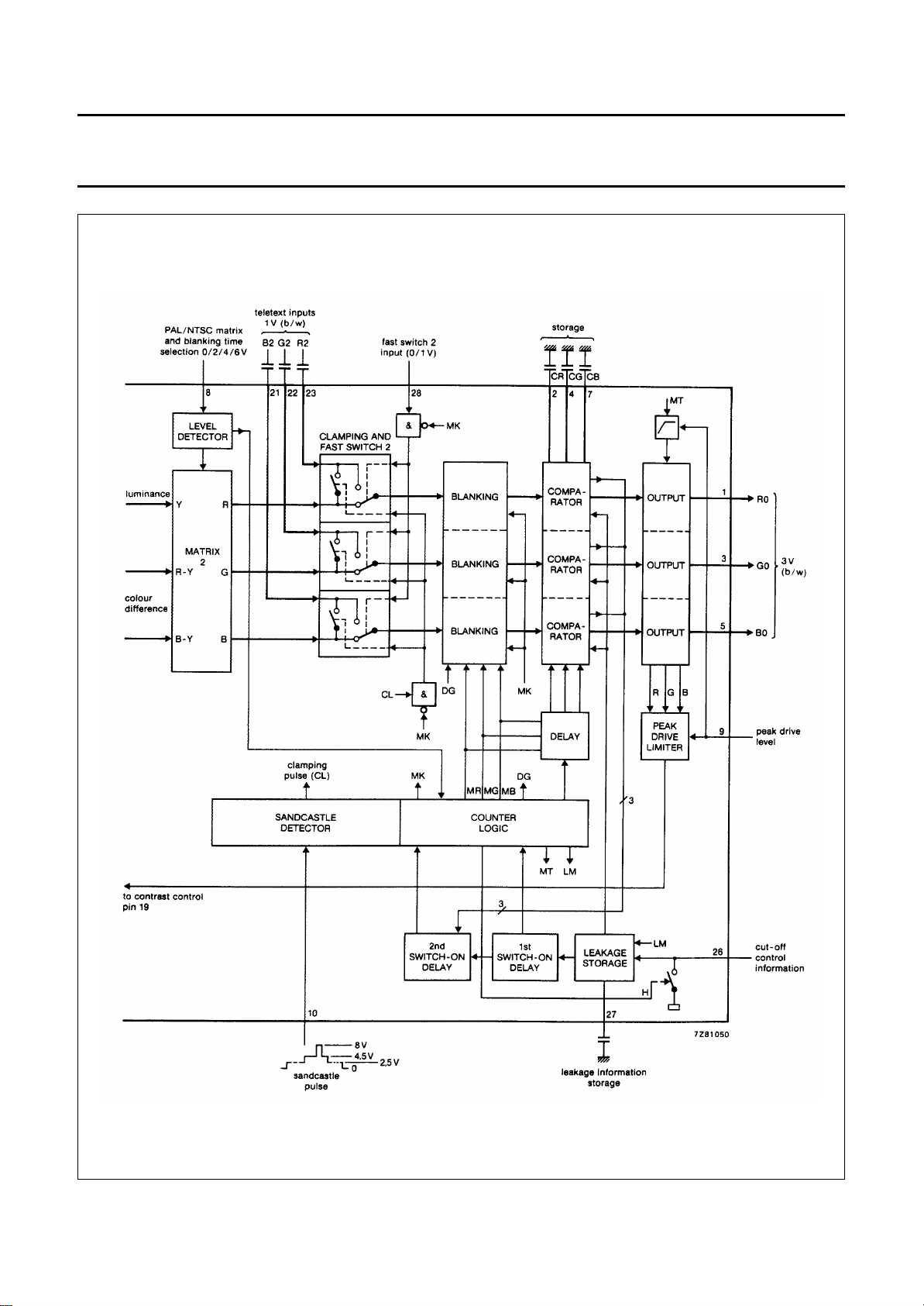
Fig.1 Part of block diagram; continued in Fig.2.
Philips Semiconductors Product specification
Video control combination circuit with
automatic cut-off control
TDA4580
March 1991 4
Fig.2 Part of block diagram; continued from Fig.1.
Philips Semiconductors Product specification
Video control combination circuit with
automatic cut-off control
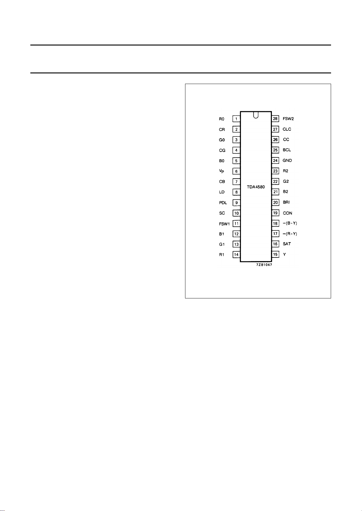
PINNING
PIN NO. MNEMONIC DESCRIPTION
1 R0 Red output
2 CR Red storage capacitor for
cut-off control
3 G0 Green output
4 CG Green storage capacitor for
cut-off control
5 B0 Blue output
6V
7 CB Blue storage capacitor for
8 LD PAL/NTSC matrix and
9 PDL Peak drive limiting input
10 SC Sandcastle pulse input
11 FSW1 Fast switch 1 for Y, CD and
12 B1 Blue input (external signal)
13 G1 Green input (external signal)
14 R1 Red input (external signal)
15 Y Luminance input
16 SAT Saturation control input
17 −(R-Y) Colour difference input −(R-Y)
18 −(B-Y) Colour difference input −(B-Y)
19 CON Contrast control input
20 BRI Brightness control input
21 B2 Teletext blue input
22 G2 Teletext green input
23 R2 Teletext red input
24 GND Ground
25 BCL Average beam current limiting
26 CC Automatic cut-off control input
27 CLC Storage capacitor for leakage
28 FSW2 Fast switch 2 for teletext
P
Positive supply voltage
(+ 12 V)
cut-off control
blanking time level detector
input
RGB inputs
input
current
inputs
TDA4580
Fig.3 Pinning diagram.
March 1991 5

Philips Semiconductors Product specification
Video control combination circuit with
automatic cut-off control
RATINGS
Limiting values in accordance with the Absolute Maximum System (IEC 134)
Supply voltage range (pin 6) V
Voltage range at pins 2, 4, 7, 9, 12, 13, 14, 15, 16,
17, 18, 19, 20, 21, 22, 23, 25, 27 to pin 24 (ground) V
Voltages ranges
at pins 8, 11, 28 V
at pin 10 V
at pin 26 V
Currents
at pins 1, 3, 5 (average) −I
at pins 1, 3, 5 (peak) −I
at pin 19 (average) I
at pin 26 I
Total power dissipation P
Storage temperature range T
Operating ambient temperature range T
= V
P
6-24
n-24
8, 11, 28-24
10-24
26-24
1, 3, 5(AV)
1, 3, 5(M)
19(AV)
26
tot
stg
amb
TDA4580
0 to 13,2 V
0 to V
P
−0,5 to V
P
0 to VP+ 0,7 V
−0,7 to VP+ 0,7 V
max. 3 mA
max. 10 mA
max. 5 mA
max. 1 mA
max. 2 W
−20 to + 150 °C
0 to + 70 °C
V
V
THERMAL RESISTANCE
From junction to ambient R
th j-a
= 37 K/W
March 1991 6
 Loading...