

Philips TDA4570 Datasheet

INTEGRATED CIRCUITS
DATA SH EET
TDA4570
NTSC decoder
Product specification
File under Integrated Circuits, IC02
August 1986

Philips Semiconductors Product specification
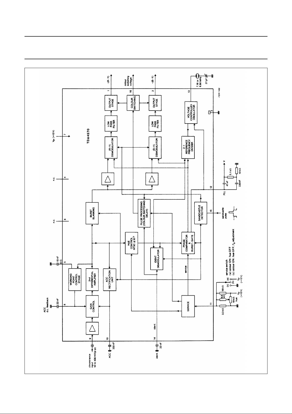
NTSC decoder TDA4570
GENERAL DESCRIPTION
The TDA4570 is an integrated 3,58 MHz or 4,43 MHz NTSC decoder. It is pin sequence compatible with multi-standard
decoder TDA4555 and pin compatible with the PAL decoder TDA4510.
Features
Chrominance part
• Gain controlled amplifier with operating point control stage
• ACC (automatic chrominance control) with sampled rectification during burst-key signal
• Blanking circuit for the colour burst signal
Oscillator and control voltage part
• Voltage controlled reference oscillator for double subcarrier frequency
• Divider stages which provide the correct 90° phase between −(R-Y) and−(B-Y) reference signals for the demodulators
• Phase comparator which controls the frequency and phase of the reference oscillator and compares the (R-Y)
reference with the burst pulse
• HUE control stage provides phase shifting via the combined service and hue control input (pin 11)
• Identification demodulator provides a positive-going identification signal at pin 14 for NTSC signals and acts as the
automatic colour killer
• Two-function service switch:
– position one (V
oscillator-OFF, allowing the adjustment of the reference oscillator
– position two (V
• Sandcastle pulse detector for burst-gate, horizontal and horizontal/vertical blanking pulse detection. The vertical part
of the sandcastle pulse is used for the internal colour-ON and colour-OFF delay
• Pulse processing part for the prevention of premature switching ON of the colour. The colour-ON delay, two or three
field periods after identification of the NTSC signal, is achieved by a counter.
When there is no identification voltage present the colour is switched OFF immediately or, at the most, one field period
later.
< 1 V): switches the colour-ON and switches the hue control and burst for the PLL
14-3
> 5 V): switches the colour-ON, the hue control OFF and allows the output signal to be observed
14-3
Demodulator part
• Two synchronous demodulators for the (R-Y) and (B-Y) signals, which incorporate stages for the blanking during line
and field flyback
• Internal filtering of the residual carrier in the demodulated colour difference signals
• Colour switching stages controlled by the pulse processing part in front of the output stages
• The output stages for (R-Y) and (B-Y) signals are low resistance n-p-n emitter followers
• Separate colour switching output
PACKAGE OUTLINE
16-lead DIL; plastic (SOT38); SOT38-1; 1996 November 28.
August 1986 2
Philips Semiconductors Product specification
NTSC decoder TDA4570
August 1986 3
Fig.1 Block diagram.
 Loading...