

Page 1

SureSigns VS1 Monitor
Instructions for Use
Part Number 9898 031 36541
Printed in the U.S.A. November, 2004
Edition 3
Page 2

Notice
Proprietary
Information
This document contains proprietary information, which is protected by copyright. All Rights
Reserved. Reproduction, adaptation, or translation without prior written permission is
prohibited, except as allowed under the copyright laws.
Philips Medical Systems
3000 Minuteman Road
Andover, MA 01810-1085
(978) 687-1501
Printed in USA
Warranty The information contained in this document is subject to change without notice.
Philips Medical Systems makes no warranty of any kind with regard to this material,
including, but not limited to, the implied warranties or merchantability and fitness for Philips
Medical Systems shall not be liable for errors contained herein or for incidental or
consequential damages in connection with the furnishing, performance, or use of this material.
Copyright Copyright © 2004 Koninklijke Philips Electronics N.V. All Rights Reserved.
OxiCliq, OxiMax, Dura-Sensor, MAX-A, MAX-AL, MAX-P, MAX-I, MAX-N, MAX-R,
MAX-FAST, and Dura-Y are registered trademarks of Nellcor.
Alaris® Turbo*Temp
®
is a registered trademark of ALARIS Medical Systems
Printing
History
Text
New editions of this document incorporate all material updated since the previous edition.
Update packages may be issued between editions and contain replacement and additional
pages to be merged by a revision date at the bottom of the page. Pages that are rearranged due
to changes on a previous page are not considered revised.
The documentation printing date and part number indicate its current edition. The printing
date changes when a new edition is printed. (Minor corrections and updates that are
incorporated at reprint do not cause the date to change.) The document part number changes
when extensive technical changes are incorporated.
First Edition ............................................................... May 2004
Second Edition ............................................................... September 2004
Third Edition ............................................................... November 2004
The following conventions for Notes, Cautions, and Warnings are used in this manual.
Conventions
Note A Note calls attention to an important point in the text.
2
Page 3

Caution A Caution calls attention to a condition or possible situation that could damage or destroy the
product or the user’s work.
Warning A Warning calls attention to a condition or possible situation that could cause injury to the
user and/or patient.
CE
Marking
Europe
United
States
The VS1 monitor complies with the requirements of Council Directive 93/43/EEC of 14 June 1993
concerning medical devices and carries CE marking accordingly .
The following accessories are independently CE marked to the Medical Device Directive. They are
not covered by the CE marking of the VS1:
Accessories: - M4552A - M4553A - M4554A - M4555A
- M4557A - M4559A - M1571A - M1572A
- M1573A - M1574A - M1575A - M1576A
- 40401A - 40401B - 40401C - 40401D
- 40401E - M1874A - M1875A - M1876A
- M1877A - M1878A - M1879A - M1866A
- M1868A - M1870A - M1872A
Accessories from companies other than Philips Medical Systems carry CE markings appropriate to
the accessory.
Additional accessories not identified above fall outside the definition of a medical device.
The Former Agilent Technologies’ Healthcare Solutions Group is now a part of Philips Medical
Systems. Some accessories may still be branded with the Agilent name.
Authorized EU-representative: Philips Medizinsystems Böblingen GmbH, Hewlett Packard Str.,
71034, Böblingen Germany
United States Federal Law restricts this device to sale by or on the order of a physician.
0123
Canada This ISM device complies with Canadian ICES-001.
Cet appareil ISM est conforme á la norme NMB-001 du Canada.
3
Page 4
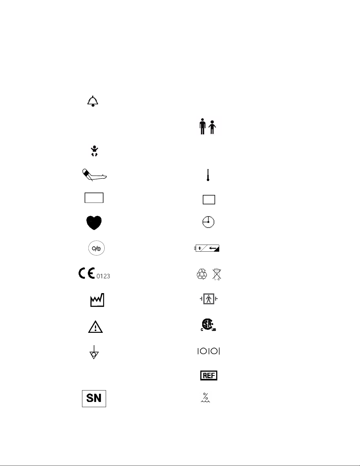
Explanation of Symbols
Symbols on products and packaging mean the following:
Sys
MAP
Alarm silence
Systolic
Neonatal measurement mode for
NIBP
NIBP Start/Stop Temperature
Mean Arterial Pressure Temperature mode
SpO
Dia
SpO
2
2
Adult/Pediatric measurement
mode for NIBP
Diastolic
T
M
Pulse Rate Time
On/Off button Battery charging indicator
This device complies with the
Council Directive 93/42/EEC of
14 June 1993 concerning
medical devices
Contains sealed lead acid
battery; battery must be
recycled.
4
Rx
Date of Manufacture
Warni ng
Equipotential Grounding
System
Federal Law restricts this device
in the United States to sale by or
on the order of a physician.
Serial number
Defibrillation proof. Type BF
Applied Part
This device complies with
Canadian Standards Association
Input/Output
Reference number
Pb
Humidity
5% to 95% RH
Page 5
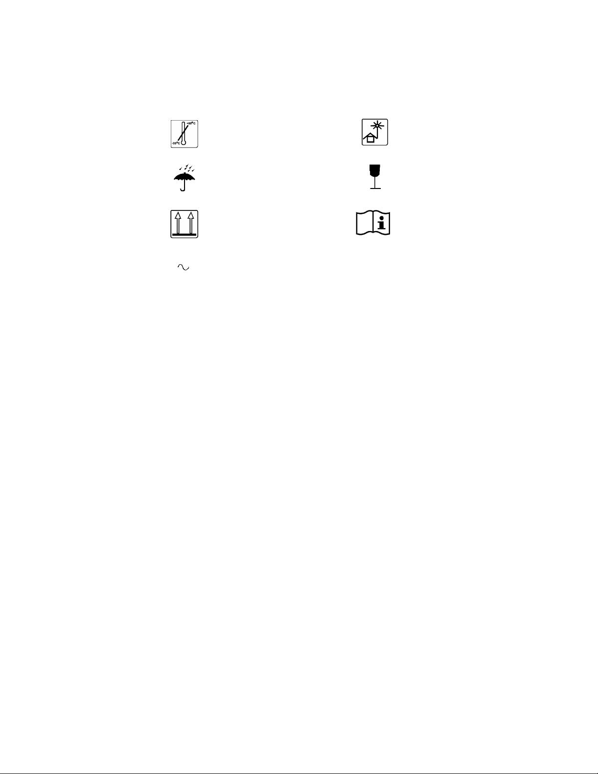
Temperature limits
Keep out of sun
Philips
Software
License
Terms
Keep dry
Keep upright
Alternating current
Fragile
Consult Instructions for Use
ATTENTION
USE OF THE SOFTWARE IS SUBJECT TO THE PHILIPS SOFTWARE LICENSE TERMS SET FORTH
BELOW. USING THE SOFTWARE INDICATES YOUR ACCEPTANCE OF THESE LICENSE TERMS. IF
YOU DO NOT ACCEPT THESE LICENSE TERMS, YOU MAY RETURN THE SOFTWARE FOR A FULL
REFUND. IF THE SOFTWARE IS BUNDLED WITH ANOTHER PRODUCT, YOU MAY RETURN THE
ENTIRE UNUSED PRODUCT FOR A FULL REFUND.
PHILIPS SOFTWARE LICENSE TERMS
The following License Terms govern your use of the accompanying Software unless you have a
separate signed agreement with Philips Medical Systems.
License Grant. Philips Medical Systems grants you a license to Use one copy of the Software.
"Use" means storing, loading, installing, executing or displaying the Software. You may not modify
the Software or disable any licensing or control features of the Software. If the Software is licensed
for "concurrent use", you may not allow more than the maximum number of authorized users to Use
the Software concurrently.
Ownership. The Software is owned and copyrighted by Philips or its third party suppliers. Your
license confers no title to, or ownership in, the Software and is not a sale of any rights in the
Software. Philips’ third party suppliers may protect their rights in the event of any violation of these
License Terms.
Copies and Adaptations. You may only make copies or adaptations of the Software for archival
purposes or when copying or adaptation is an essential step in the authorized Use of the Software.
You must reproduce all copyright notices in the original Software on all copies or adaptations. You
may not copy the Software onto any public network.
No Disassembly or Decryption. You may not disassemble or decompile the Software unless
Philips prior written consent is obtained. In some jurisdictions, Philips consent may not be required
for limited disassembly or decompilation. Upon request, you will provide Philips with reasonably
detailed information regarding any disassembly or decompilation. You may not decrypt the
Software unless decryption is a necessary part of the operation of the Software.
5
Page 6

Transfer. Your license will automatically terminate upon any transfer of the Software. Upon
transfer, you must deliver the Software, including any copies and related documentation, to the
transferee. The transferee must accept these License Terms as a condition to the transfer.
Termination. Philips Medical Systems may terminate your license upon notice for failure to
comply with any of these License Terms. Upon termination, you must immediately destroy the
Software, together with all copies, adaptations and merged portions in any form.
Export Requirements. You may not export or re-export the Software or any copy or adaptation in
violation of any applicable laws or regulations.
U.S. Government Restricted Rights. The Software and any accompanying documentation have
been developed entirely at private expense. They are delivered and licensed as "commercial
computer software" as defined in DFARS 252.227-7013 (Oct. 1988), DFARS 252.211-7015 (May
1991) or DFARS 252.227-7014 (Jun. 1995), as a "commercial item" as defined in FAR 2.101(a), or
as "Restricted computer software" as defined in FAR 52.227-19 (Jun. 1987)(or any equivalent
agency regulation or contract clause), whichever is applicable. You have only those rights provided
for such Software and any accompanying documentation by the applicable FAR or DFARS clause
or the Philips standard software agreement for the product involved.
6
Page 7

Contents
1. Overview . . . . . . . . . . . . . . . . . . . . . . . . . . . . . . . . . . . . . . . . . . . . . . . . . . . . . . . 1-1
Introduction . . . . . . . . . . . . . . . . . . . . . . . . . . . . . . . . . . . . . . . . . . . . . . . . . . . . . . . . . . . . . . . . . .1-1
Intended Use . . . . . . . . . . . . . . . . . . . . . . . . . . . . . . . . . . . . . . . . . . . . . . . . . . . . . . . . . . . . . . . . .1-2
About this Book . . . . . . . . . . . . . . . . . . . . . . . . . . . . . . . . . . . . . . . . . . . . . . . . . . . . . . . . . . . . . . .1-2
VS1 Configurations . . . . . . . . . . . . . . . . . . . . . . . . . . . . . . . . . . . . . . . . . . . . . . . . . . . . . . . . . . . .1-2
2. Setting Up the Monitor. . . . . . . . . . . . . . . . . . . . . . . . . . . . . . . . . . . . . . . . . . . . 2-1
Checking the Shipment . . . . . . . . . . . . . . . . . . . . . . . . . . . . . . . . . . . . . . . . . . . . . . . . . . . . . . . . .2-1
Setting Up the Monitor . . . . . . . . . . . . . . . . . . . . . . . . . . . . . . . . . . . . . . . . . . . . . . . . . . . . . . . . .2-1
Powering Up and Down . . . . . . . . . . . . . . . . . . . . . . . . . . . . . . . . . . . . . . . . . . . . . . . . . . . . . . . . .2-3
Sleep Mode . . . . . . . . . . . . . . . . . . . . . . . . . . . . . . . . . . . . . . . . . . . . . . . . . . . . . . . . . . . . . . .2-3
Recharging the Battery. . . . . . . . . . . . . . . . . . . . . . . . . . . . . . . . . . . . . . . . . . . . . . . . . . . . . . . . . .2-3
Disposing of the Monitor . . . . . . . . . . . . . . . . . . . . . . . . . . . . . . . . . . . . . . . . . . . . . . . . . . . . . . . .2-4
3. Operating Your Monitor . . . . . . . . . . . . . . . . . . . . . . . . . . . . . . . . . . . . . . . . . . 3-1
Using the Monitor Safely . . . . . . . . . . . . . . . . . . . . . . . . . . . . . . . . . . . . . . . . . . . . . . . . . . . . . . . .3-1
LCD Screen Displays. . . . . . . . . . . . . . . . . . . . . . . . . . . . . . . . . . . . . . . . . . . . . . . . . . . . . . . . . . .3-2
Line List Display . . . . . . . . . . . . . . . . . . . . . . . . . . . . . . . . . . . . . . . . . . . . . . . . . . . . . . . . . .3-2
Soft Keys. . . . . . . . . . . . . . . . . . . . . . . . . . . . . . . . . . . . . . . . . . . . . . . . . . . . . . . . . . . . . . . . .3-3
Saving Data . . . . . . . . . . . . . . . . . . . . . . . . . . . . . . . . . . . . . . . . . . . . . . . . . . . . . . . . . . . . . . . . . .3-3
Changing the Save Rate . . . . . . . . . . . . . . . . . . . . . . . . . . . . . . . . . . . . . . . . . . . . . . . . . . . . .3-3
Clearing Data from Memory . . . . . . . . . . . . . . . . . . . . . . . . . . . . . . . . . . . . . . . . . . . . . . . . . . . . .3-4
Changing the System Date and Time. . . . . . . . . . . . . . . . . . . . . . . . . . . . . . . . . . . . . . . . . . . . . . .3-4
4. Entering Patient ID Information. . . . . . . . . . . . . . . . . . . . . . . . . . . . . . . . . . . . 4-1
Using the Bar Code Scanner to Enter Patient IDs . . . . . . . . . . . . . . . . . . . . . . . . . . . . . . . . . . . . .4-1
Entering Patient IDs Manually. . . . . . . . . . . . . . . . . . . . . . . . . . . . . . . . . . . . . . . . . . . . . . . . . . . .4-2
Adding Measurements to an Existing Patient Record . . . . . . . . . . . . . . . . . . . . . . . . . . . . . . . . . .4-2
5. Monitoring Blood Pressure . . . . . . . . . . . . . . . . . . . . . . . . . . . . . . . . . . . . . . . . 5-1
Blood Pressure Controls. . . . . . . . . . . . . . . . . . . . . . . . . . . . . . . . . . . . . . . . . . . . . . . . . . . . . . . . .5-1
NIBP Safety Information . . . . . . . . . . . . . . . . . . . . . . . . . . . . . . . . . . . . . . . . . . . . . . . . . . . . . . . .5-2
Connecting the NIBP Cuff and Hose . . . . . . . . . . . . . . . . . . . . . . . . . . . . . . . . . . . . . . . . . . . . . . .5-2
Smart Inflation Feature . . . . . . . . . . . . . . . . . . . . . . . . . . . . . . . . . . . . . . . . . . . . . . . . . . . . . . . . .5-2
Specifying Cuff Settings . . . . . . . . . . . . . . . . . . . . . . . . . . . . . . . . . . . . . . . . . . . . . . . . . . . . . . . .5-3
Selecting a Measurement Mode . . . . . . . . . . . . . . . . . . . . . . . . . . . . . . . . . . . . . . . . . . . . . . .5-3
Specifying an Initial Inflation Value . . . . . . . . . . . . . . . . . . . . . . . . . . . . . . . . . . . . . . . . . . .5-4
Enabling the BP Alarm Option . . . . . . . . . . . . . . . . . . . . . . . . . . . . . . . . . . . . . . . . . . . . . . . .5-4
Enabling Smart Clock for Interval NIBP Readings . . . . . . . . . . . . . . . . . . . . . . . . . . . . . . . .5-4
Placing the Cuff . . . . . . . . . . . . . . . . . . . . . . . . . . . . . . . . . . . . . . . . . . . . . . . . . . . . . . . . . . . . . . .5-4
Initiating a Single NIBP Measurement . . . . . . . . . . . . . . . . . . . . . . . . . . . . . . . . . . . . . . . . . . . . .5-5
Continuous NIBP Monitoring . . . . . . . . . . . . . . . . . . . . . . . . . . . . . . . . . . . . . . . . . . . . . . . . . . . .5-5
Selecting a Cuff Interval . . . . . . . . . . . . . . . . . . . . . . . . . . . . . . . . . . . . . . . . . . . . . . . . . . . . .5-5
Selecting a Cuff Interval Program . . . . . . . . . . . . . . . . . . . . . . . . . . . . . . . . . . . . . . . . . . . . .5-6
Stopping Interval Measurements . . . . . . . . . . . . . . . . . . . . . . . . . . . . . . . . . . . . . . . . . . . . . .5-8
6. Monitoring Temperature. . . . . . . . . . . . . . . . . . . . . . . . . . . . . . . . . . . . . . . . . . 6-1
Temperature Controls . . . . . . . . . . . . . . . . . . . . . . . . . . . . . . . . . . . . . . . . . . . . . . . . . . . . . . . . . .6-1
Temperature Safety Information . . . . . . . . . . . . . . . . . . . . . . . . . . . . . . . . . . . . . . . . . . . . . . . . . .6-2
Setting the Measurement Mode . . . . . . . . . . . . . . . . . . . . . . . . . . . . . . . . . . . . . . . . . . . . . . . . . . .6-2
Temperature Mode LED . . . . . . . . . . . . . . . . . . . . . . . . . . . . . . . . . . . . . . . . . . . . . . . . . . . . .6-2
Selecting a Probe . . . . . . . . . . . . . . . . . . . . . . . . . . . . . . . . . . . . . . . . . . . . . . . . . . . . . . . . . . . . . .6-3
Taking a Single Temperature Measurement . . . . . . . . . . . . . . . . . . . . . . . . . . . . . . . . . . . . . . . . .6-3
Measuring Temperature Continuously. . . . . . . . . . . . . . . . . . . . . . . . . . . . . . . . . . . . . . . . . . . . . .6-4
Contents-1
Page 8

7. Monitoring SpO2 and Pulse Rate . . . . . . . . . . . . . . . . . . . . . . . . . . . . . . . . . . . 7-1
SpO2 and Pulse Controls . . . . . . . . . . . . . . . . . . . . . . . . . . . . . . . . . . . . . . . . . . . . . . . . . . . . . . . .7-1
SpO2 Safety Information . . . . . . . . . . . . . . . . . . . . . . . . . . . . . . . . . . . . . . . . . . . . . . . . . . . . . . . .7-2
Selecting a Sensor . . . . . . . . . . . . . . . . . . . . . . . . . . . . . . . . . . . . . . . . . . . . . . . . . . . . . . . . . . . . .7-3
Placing the Reusable Sensor . . . . . . . . . . . . . . . . . . . . . . . . . . . . . . . . . . . . . . . . . . . . . . . . . . . . .7-3
Placing the Disposable Sensor . . . . . . . . . . . . . . . . . . . . . . . . . . . . . . . . . . . . . . . . . . . . . . . . . . . .7-4
8. Setting Alarms. . . . . . . . . . . . . . . . . . . . . . . . . . . . . . . . . . . . . . . . . . . . . . . . . . . 8-1
Alarm Controls. . . . . . . . . . . . . . . . . . . . . . . . . . . . . . . . . . . . . . . . . . . . . . . . . . . . . . . . . . . . . . . .8-1
Changing Alarm Limits . . . . . . . . . . . . . . . . . . . . . . . . . . . . . . . . . . . . . . . . . . . . . . . . . . . . . . . . .8-2
Setting Patient-Specific Alarm Limits . . . . . . . . . . . . . . . . . . . . . . . . . . . . . . . . . . . . . . . . . . . . . .8-3
Changing Audible Alarm Settings . . . . . . . . . . . . . . . . . . . . . . . . . . . . . . . . . . . . . . . . . . . . . . . . .8-3
Adjusting the Volume . . . . . . . . . . . . . . . . . . . . . . . . . . . . . . . . . . . . . . . . . . . . . . . . . . . . . . .8-4
Silencing the Alarm . . . . . . . . . . . . . . . . . . . . . . . . . . . . . . . . . . . . . . . . . . . . . . . . . . . . . . . .8-4
9. Recording and Printing Results. . . . . . . . . . . . . . . . . . . . . . . . . . . . . . . . . . . . . 9-1
Loading the Paper . . . . . . . . . . . . . . . . . . . . . . . . . . . . . . . . . . . . . . . . . . . . . . . . . . . . . . . . . . . . .9-1
Printing Automatically . . . . . . . . . . . . . . . . . . . . . . . . . . . . . . . . . . . . . . . . . . . . . . . . . . . . . . . . . .9-1
Printing Only When an Alarm Occurs . . . . . . . . . . . . . . . . . . . . . . . . . . . . . . . . . . . . . . . . . . . . . .9-2
Selecting Additional Print Options . . . . . . . . . . . . . . . . . . . . . . . . . . . . . . . . . . . . . . . . . . . . . . . .9-2
Printing Vital Signs for the Current Patient . . . . . . . . . . . . . . . . . . . . . . . . . . . . . . . . . . . . . .9-3
Printing Vital Signs by Patient ID . . . . . . . . . . . . . . . . . . . . . . . . . . . . . . . . . . . . . . . . . . . . .9-3
Printing All Currently Displayed Records . . . . . . . . . . . . . . . . . . . . . . . . . . . . . . . . . . . . . . .9-3
Printing All Records in Memory . . . . . . . . . . . . . . . . . . . . . . . . . . . . . . . . . . . . . . . . . . . . . .9-3
Print Formats . . . . . . . . . . . . . . . . . . . . . . . . . . . . . . . . . . . . . . . . . . . . . . . . . . . . . . . . . . . . . . . . .9-3
Vital Signs Print Format . . . . . . . . . . . . . . . . . . . . . . . . . . . . . . . . . . . . . . . . . . . . . . . . . . . . .9-4
Line List Print Format. . . . . . . . . . . . . . . . . . . . . . . . . . . . . . . . . . . . . . . . . . . . . . . . . . . . . . .9-4
10. Troubleshooting and Maintenance . . . . . . . . . . . . . . . . . . . . . . . . . . . . . . . . 10-1
Problems with the Monitor . . . . . . . . . . . . . . . . . . . . . . . . . . . . . . . . . . . . . . . . . . . . . . . . . . . . .10-1
Recorder Problems . . . . . . . . . . . . . . . . . . . . . . . . . . . . . . . . . . . . . . . . . . . . . . . . . . . . . . . . . . . .10-2
NIBP Problems . . . . . . . . . . . . . . . . . . . . . . . . . . . . . . . . . . . . . . . . . . . . . . . . . . . . . . . . . . . . . .10-3
Temperature Problems . . . . . . . . . . . . . . . . . . . . . . . . . . . . . . . . . . . . . . . . . . . . . . . . . . . . . . . . .10-4
SpO
Problems. . . . . . . . . . . . . . . . . . . . . . . . . . . . . . . . . . . . . . . . . . . . . . . . . . . . . . . . . . . . . . .10-5
2
Bar Code Scanner Problems . . . . . . . . . . . . . . . . . . . . . . . . . . . . . . . . . . . . . . . . . . . . . . . . . . . .10-6
Error and Informational Messages. . . . . . . . . . . . . . . . . . . . . . . . . . . . . . . . . . . . . . . . . . . . . . . .10-6
Battery Care and Replacement. . . . . . . . . . . . . . . . . . . . . . . . . . . . . . . . . . . . . . . . . . . . . . . . . . .10-7
Internal Fuse Replacement. . . . . . . . . . . . . . . . . . . . . . . . . . . . . . . . . . . . . . . . . . . . . . . . . . . . . .10-8
Cleaning the Monitor . . . . . . . . . . . . . . . . . . . . . . . . . . . . . . . . . . . . . . . . . . . . . . . . . . . . . . . . . .10-8
Accidental Wetting of the Monitor . . . . . . . . . . . . . . . . . . . . . . . . . . . . . . . . . . . . . . . . . . . .10-8
Cleaning the Accessories . . . . . . . . . . . . . . . . . . . . . . . . . . . . . . . . . . . . . . . . . . . . . . . . . . . . . . .10-8
11. Specifications. . . . . . . . . . . . . . . . . . . . . . . . . . . . . . . . . . . . . . . . . . . . . . . . . . 11-1
Monitor Specifications . . . . . . . . . . . . . . . . . . . . . . . . . . . . . . . . . . . . . . . . . . . . . . . . . . . . . . . . .11-1
Recorder Specifications . . . . . . . . . . . . . . . . . . . . . . . . . . . . . . . . . . . . . . . . . . . . . . . . . . . . . . . .11-1
Environmental Specifications . . . . . . . . . . . . . . . . . . . . . . . . . . . . . . . . . . . . . . . . . . . . . . . . . . .11-1
NIBP Specifications. . . . . . . . . . . . . . . . . . . . . . . . . . . . . . . . . . . . . . . . . . . . . . . . . . . . . . . . . . .11-2
SpO
Sensor Specifications . . . . . . . . . . . . . . . . . . . . . . . . . . . . . . . . . . . . . . . . . . . . . . . . . . . . .11-2
2
Temperature Specifications . . . . . . . . . . . . . . . . . . . . . . . . . . . . . . . . . . . . . . . . . . . . . . . . . . . . .11-2
Barcode Reader Specifications . . . . . . . . . . . . . . . . . . . . . . . . . . . . . . . . . . . . . . . . . . . . . . . . . .11-3
12. Accessory List . . . . . . . . . . . . . . . . . . . . . . . . . . . . . . . . . . . . . . . . . . . . . . . . . 12-1
Standard Accessories . . . . . . . . . . . . . . . . . . . . . . . . . . . . . . . . . . . . . . . . . . . . . . . . . . . . . . . . . .12-1
Optional Accessories . . . . . . . . . . . . . . . . . . . . . . . . . . . . . . . . . . . . . . . . . . . . . . . . . . . . . . . . . .12-1
Contents-2
Page 9

A. Electromagnetic Compatibility. . . . . . . . . . . . . . . . . . . . . . . . . . . . . . . . . . . . A-1
Reducing Electromagnetic Interference . . . . . . . . . . . . . . . . . . . . . . . . . . . . . . . . . . . . . . . . A-1
Restrictions for Use . . . . . . . . . . . . . . . . . . . . . . . . . . . . . . . . . . . . . . . . . . . . . . . . . . . . . . . A-2
Emissions and Immunity . . . . . . . . . . . . . . . . . . . . . . . . . . . . . . . . . . . . . . . . . . . . . . . . . . . A-2
Guidance and Manufacturer’s Declaration . . . . . . . . . . . . . . . . . . . . . . . . . . . . . . . . . . . . . . A-2
Recommended Separation Distances . . . . . . . . . . . . . . . . . . . . . . . . . . . . . . . . . . . . . . . . . . A-5
Contents-3
Page 10

Contents-4
Page 11
This chapter provides a brief overview of the VS1 patient monitor, its intended use, and available
configurations.
Introduction
The VS1 monitor is a portable vital signs monitor. It can be used to non-invasively and automatically
measure systolic, mean and diastolic blood pressures, pulse rate, oxygen saturation (SpO
You can measure all of these vital signs if you purchased a fully configured model; other models contain a
subset of these features.
SpO
1
Overview
) and temperature.
2
2
Sys
º
C
M
%
º
F
Sys/Dia MAP
VS
kpa mmhg
Dia
MAP
bpm
SpO
2
OK
1
Overview 1-1
Page 12

Intended Use
Large, colored LEDs display the current parameters. To increase readability, each parameter has its own
unique color. A large LCD screen displays historical information and is also used to configure the system.
The monitor uses dynamic linear deflation blood pressure technology and features a full array of alarm
settings for each displayed parameter. It can hold up to 400 lines of data that can be viewed or printed in
several formats.
The monitor can operate on AC power or on a 6-volt internal battery.
Intended Use
The VS1 monitor is intended to monitor a single patient’s vital signs in a hospital, outpatient surgery,
practitioner facilities, or in an environment where patient care is provided by qualified healthcare personnel
who will determine when use of the device is indicated, based upon their professional assessment of the
patient’s medical condition. The patient populations are adult, pediatric, and neonatal.
The device is capable of monitoring pulse rate, non-invasive blood pressure, temperature, and SpO
device is intended for use by qualified healthcare personnel trained in its use.
About this Book
This book explains how to set up and use the VS1 monitor. It contains information on all available features
and parameters and, therefore, may contain information that does not apply to your monitor. It is intended
as a comprehensive guide to the operation of the unit and should be read carefully prior to using the unit.
Additional documentation includes a set of Quick Reference Cards and a Service Manual.
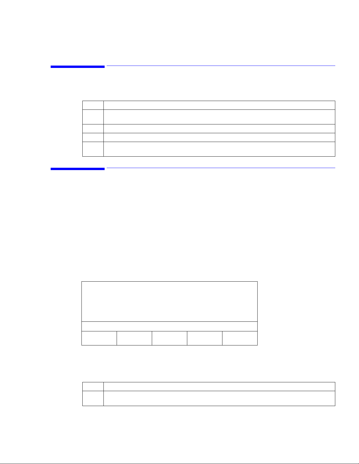
VS1 Configurations
The VS1 monitor is available in several configurations. A fully configured VS1 monitor has NIBP, SpO
and Temperature parameters, plus a printer. The following table lists each model, configuration, and
corresponding Philips part number.
Philips Product
Number
863055 NIBP only PM2200
863057 NIBP with recorder PM2200P
863061 NIBP, SpO
863059 NIBP, SpO
863056 NIBP, Temp PM2220
863058 NIBP, Temp with recorder PM2220P
863062 NIBP, SpO
863060 NIBP, SpO
Configuration Model number
2
with recorder PM2210P
2
Temp PM2240
2,
Temp with recorder PM2240P
2,
PM2210
. The
2
2,
1-2 Overview
Page 13

This chapter describes how to install connectors and cables, power up the monitor, and recharge the battery.
Note—
Philips recommends that the user has a clear understanding of the VS1 monitor, its intended use,
warnings, precautions, and the other information found in this manual before using this device for patient
monitoring.
Checking the Shipment
Examine the carton carefully for evidence of damage in transit. If you discover any damage, contact the
carrier immediately. Retain all packing material.
If you have to return the monitor, contact the Philips Response Center or your local Philips representative
for shipping instructions. The device should be cleaned and disinfected prior to shipping.
To pack the monitor, disconnect all cables. Pack the monitor in its original shipping carton. If this is
unavailable, use a suitable carton with appropriate packing material to protect the monitor during shipping.
Note—
Do not return sensors, patient cables, NIBP tubing and cuff, or the power cord.
2
Setting Up the Monitor
Setting Up the Monitor
Caution—Use only the approved accessories for the VS1 monitor. See Chapter 12, Accessory List, for a
list of all approved accessories.
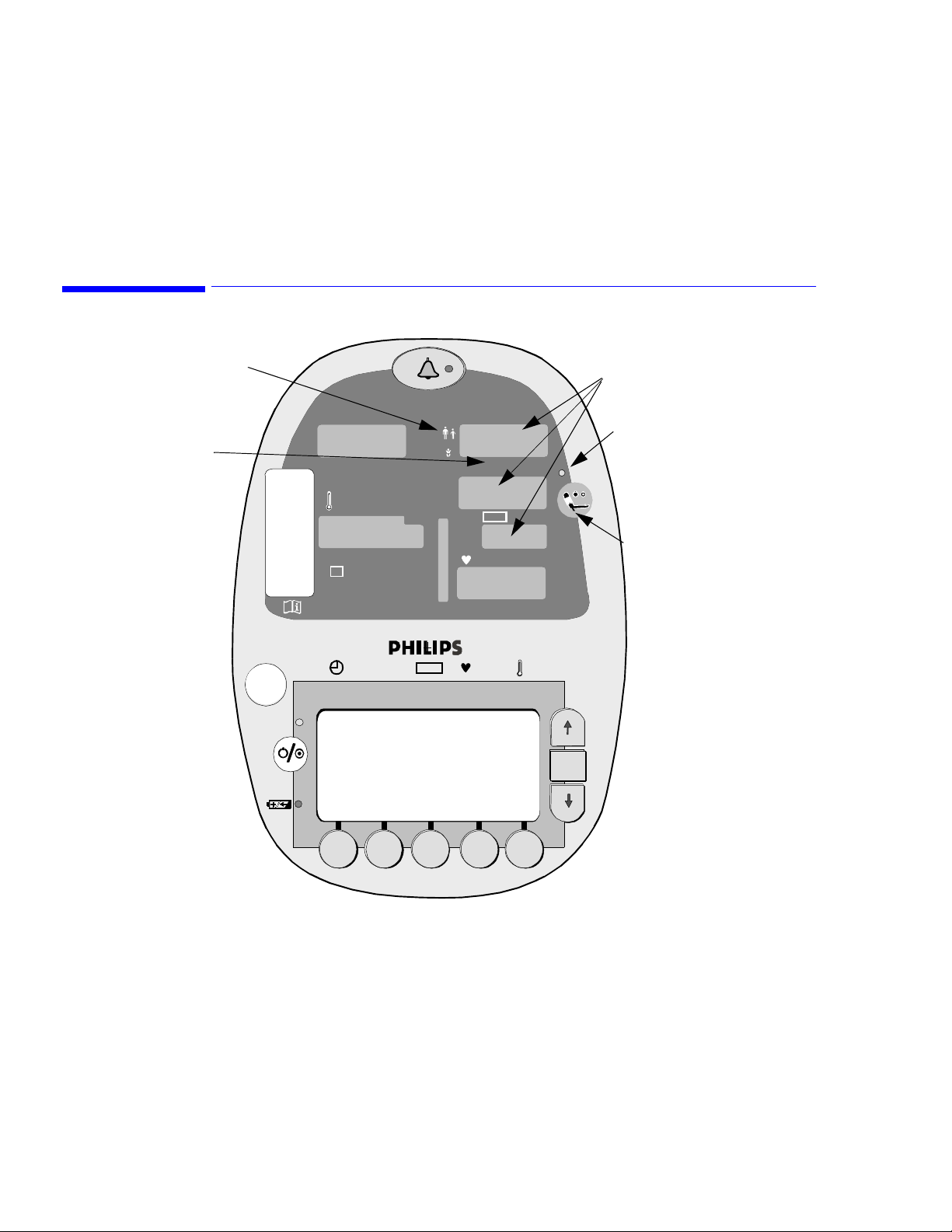
The following procedure explains how to connect all of the accessories on a fully configured model. If you
do not have all of the accessories, skip those steps that do not apply to your monitor. Refer to the following
diagram for connector locations.
Note—
If you power up the monitor before connecting all of the accessories, an alarm sounds and one or
more error messages appear on the LCD screen. To avoid these alarms, connect all accessories before
powering up the monitor.
Setting Up the Monitor 2-1
Page 14
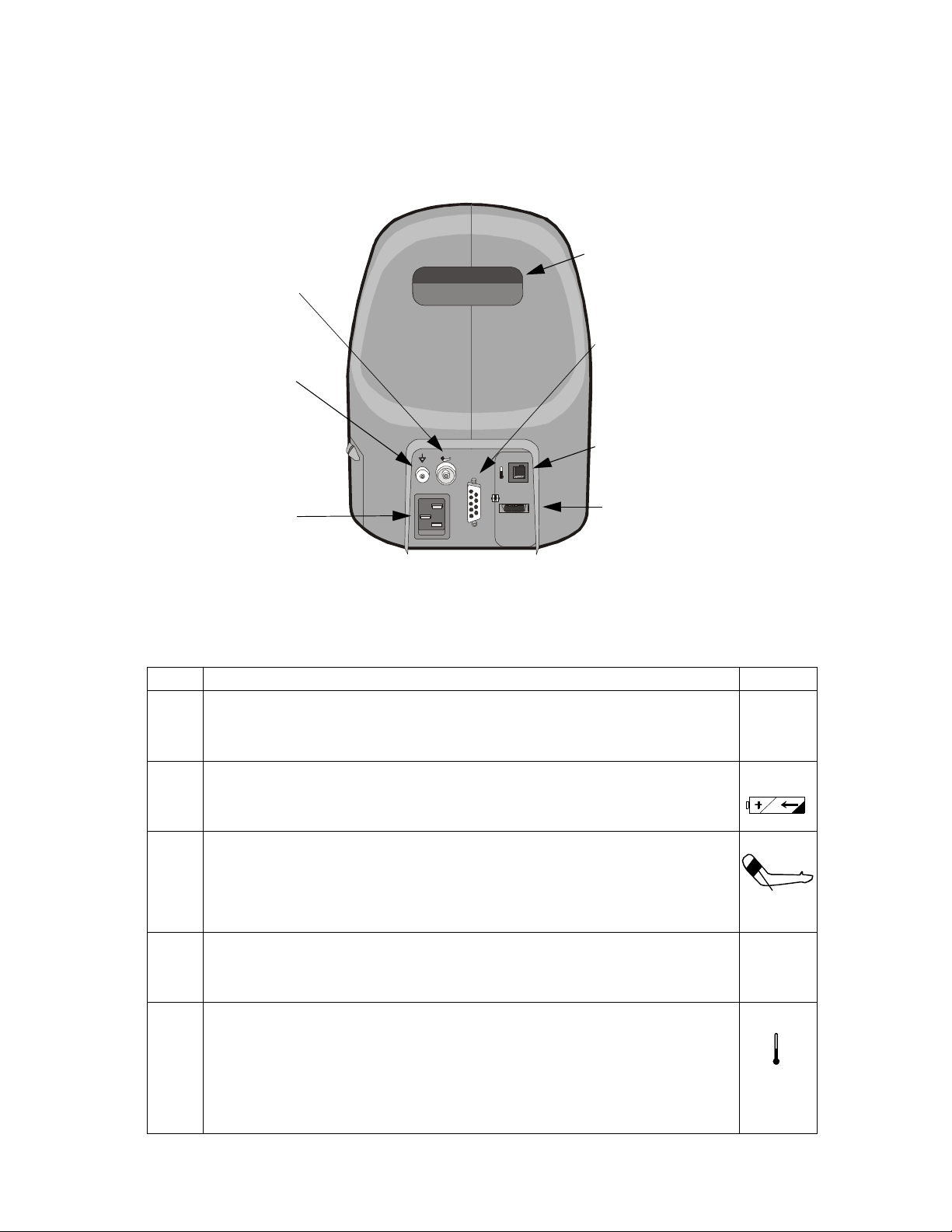
Setting Up the Monitor
NIBP Hose Connector
3
Handle
1
Barcode Scanner I/O
Connector
Biomed Ground Lug
AC Plug Receptacle
1
Connect only EN 60601-1 compliant devices, as specified by Philips.
2
The Biomed ground lug is an additional ground point that can be used by a Biomed when external grounding is
2
Temperature Probe Connector
T
AC 100 ~ 240
50/60 Hz, 2V A
Internally Fused 2A
Rs23 2
SpO2
SpO2 Cable Connector
1
needed.
3
The handle may feel warm because it is also used as an exhaust port for the unit.
Step Action Label
1 Connect the monitor to a grounded, 3-wire, hospital grade AC power source.
Caution—Use only the supplied power cord. If in doubt about the integrity of the
100 - 240V
50/60 Hz
120VA max
grounding of the AC power source, operate the monitor only from its battery.
2 Verify that the Battery Charging Indicator LED is on. Allow the unit to fully charge before
operating. See Recharging the Battery on page 2-3 for more information.
1
3 Attach the appropriate blood pressure hose to the NIBP hose connector on the back of the
monitor.
Select the appropriate sized BP cuff and attach it to the hose. Sizes range from neonatal to
large adult and thigh. For more information about choosing a BP cuff, see
Chapter 5, “Monitoring Blood Pressure.”
4 Connect the SpO
will have a positive lock on the cable when inserted correctly.
Select the appropriate SpO
5 Connect the appropriate temperature probe (oral or rectal) by connecting the temperature
probe cable to the temperature probe connector on the back of the monitor. Push the cable
connector in until a positive latch is made.
Note: For oral temperature measurements, use the blue probe; for rectal, use the red probe.
Insert the probe into the probe well and place a new box of probe covers into the probe
cover box receptacle.
2-2 Setting Up the Monitor
extension cable to the SpO2 connector on the back of the monitor.You
2
sensor and attach it to the extension cable.
2
SpO
2
T
Page 15
Powering Up and Down
Step Action Label
6 If your monitor includes a printer, load the paper by following the instructions in Chapter 9,
Recording and Printing Results.
7 Connect the bar code scanner interface cable to the back of the VS1 monitor on the
I/O connector. Secure the cable in place by tightening the top and bottom retaining screws
in the connector.
Attach the scanner’s mounting arm to the roll stand just below the unit so that the scanner is
held to one side of the unit. Tighten the arm’s mount by tightening the two allen bolts with
the appropriate wrench.
Attach the enclosed “Scanner Reset” label to the scanner’s mounting arm for easy access
when needed. This label is used to reset the scanner when it appears the scanner is no longer
reading the patient’s bar code correctly.
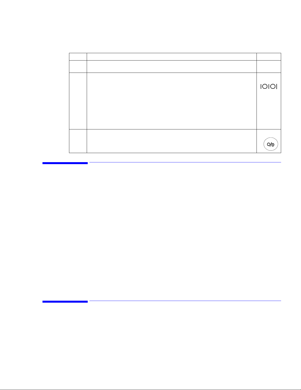
8 Press the Power ON/OFF button on the lower left corner of the front panel of the monitor.
Powering Up and Down
After you press the Power On/Off button, the Power On LED turns green, and the unit then initializes and
performs a self-test. During this process, 888 appears in all of the LED displays. As each parameter is
initialized, the displays change from 888 to --- and the Line List display (the Main screen) appears on the
LCD screen. After this verification is complete for all parameters (about 10 seconds), the monitor is ready
for use.
To turn the monitor off, press and hold the button for at least three seconds. A beep tone will sound at onesecond intervals until the unit turns off (in approximately 3 seconds).
Sleep Mode
If the monitor is on, but it is not used for five minutes, it enters Sleep mode. Sleep mode can also be entered
by briefly pressing the Power On/Off button. In Sleep mode, all parameters are suspended, which decreases
power discharge when the monitor is running on battery and decreases battery charging when the monitor is
plugged in to an AC power supply.
Push any button to power up the unit. The initialization process begins and the parameters will become
active in approximately 10 seconds.
Sleep mode is the default setting. If the monitor will normally be on AC power, it can be set to bypass S
leep mode. Contact your biomed to change this setting.
Recharging the Battery
The VS1 is shipped with a fully charged battery. The battery recharges automatically any time the power
cord is plugged into an AC power source. Recharging from a fully drained battery to a fully charged battery
can take up to four hours.
Setting Up the Monitor
2-3
Page 16

Disposing of the Monitor
The Battery Charging Indicator LED on the front of the monitor shows the charging status when
the unit is plugged in.
When the monitor is on, but is not plugged in, the Battery Indicator icon, which is located in the lower right
portion of the Line List display, also indicates current battery power levels.
Note—
Always verify that the Battery Charging Indicator LED is lit when the unit is connected to an AC
outlet. A monitor that is plugged in, but shows no Battery Charging light indicates a problem with the
charging of the monitor. See the Troubleshooting section for information.
A fully charged battery (more than 90% of capacity) will normally last more than six hours at 15-minute
spot-check measurement frequencies. If the monitor is stationary, it should be connected to an AC power
supply to help ensure maximum battery power availability.
Note—
If the monitor will not be used for an extended period of time, remove the battery.
For information on removing or replacing the battery, see the Service manual.
Color Status
Red The battery is charging.
Green The battery is fully charged and ready to use.
Note—
If, after fully charging the battery, you unplug the monitor, and then plug it back in, the Battery
Charging LED will turn red. To determine the current battery power level, see the Battery Indicator icon in
the lower right corner of the main screen. This icon appears when the unit is unplugged.
Disposing of the Monitor
To avoid contaminating or infecting personnel, the environment or other equipment, make sure you
disinfect and decontaminate the monitor appropriately before disposing of it in accordance with your
country’s law for equipment containing electrical and electronic parts.
For disposal of parts and accessories, such as SpO
regarding disposal of hospital waste.
For disposal of the lead-acid battery, follow local regulations for safe disposal of lead.
, where not otherwise specified, follow local regulations
2
2-4 Setting Up the Monitor
Page 17

This chapter describes some of the basic functionality of the VS1 monitor. It includes information on using
the controls to change system settings, save data, and change the system date and time.
Note—
This manual describes the fully configured VS1 monitor (model PM2240P) which includes NIBP,
Pulse, Pulse Oximetry, and Temperature displays, plus a recorder. If you do not have a fully configured
monitor, some of the information in this manual may not apply to your unit.
Using the Monitor Safely
Ensure that the monitor is in proper working condition before clinical use. If the accuracy of any
measurement does not seem reasonable, first check the patient’s vital signs by alternative means and then
with the monitor to make sure it is working properly.
If you connect the monitor to any instrument, verify proper operation before clinical use. Refer to that
instrument’s Instructions for Use guide for full instructions.
Anyone who connects additional equipment to the signal input port or signal output port configures a
medical system and is therefore responsible to ensure that the system complies with the requirements of
system standard IEC Standard 60601-1. If in doubt, contact the Philips Response Center or your local
Philips representative.
3
Operating Your Monitor
The care and handling of all accessories should be in accordance with local hospital guidelines, policies,
and procedures.
Note—
The monitor and its accessories must be tested by qualified service personnel at regular intervals to
verify proper operation, according to the procedures of the user’s institution.
Warning Explosion hazard. Equipment not suitable for use in the presence of a flammable anesthetic mixture
with air, or with oxygen or nitrous oxide.
Electric shock hazard. Covers should be removed only by qualified service personnel. There are no
user-serviceable parts inside.
If you suspect a problem with parts inside the monitor, unplug the device and contact your biomed or
local Philips representative. Do not open the monitor or attempt to change the battery.
Do not connect accessory equipment to the monitor’s data interface.
Route patient cabling to reduce the possibility of patient entanglement or strangulation.
Do not place the monitor in any position that might cause it to fall on the patient. Do not lift the
monitor by the power supply cord or patient connections because disconnection could then result in
the monitor dropping on the patient.
Service should be performed by qualified service personnel only.
This device can be damaged by energy discharged from a defibrillator. Disconnect the SpO
temperature probes from the monitor before defibrillator discharge.
All wire-lead patient-connected transducer assemblies are subject to reading error, local heating, and
possible damage from high-intensity sources of RF energy. Electro-surgical equipment’s capacitivelycoupled currents may seek alternate paths to ground through probe cables and associated
instruments; patient burns may result. If possible, remove the probes from patient before activating
the surgical unit or other RF source. To reduce hazards, select a temperature monitoring point that is
remote from the expected RF current path to ground return pad. Appropriate probe selection and
application must be determined then applied.
and
2
Operating Your Monitor 3-1
Page 18
LCD Screen Displays
To ensure patient electrical isolation, connect only to other equipment that provides patient electrical
isolation.
Do not use extension cords to connect the monitor to electrical outlets.
Do not use the monitor during MRI (magnetic resonance imaging) scanning. Induced current could
potentially cause burns. The monitor may affect the MRI image, and the MRI unit may affect the
accuracy of the monitor’s measurements.
Sterilization is not recommended for this monitor, related products, accessories or supplies unless
otherwise indicated in the Instructions for Use for the accessories and supplies.
Electromagnetic interference may cause disruption of performance. Protect the monitor from sources
of intense electromagnetic radiation. This device is designed to provide resistance to electromagnetic
interference. However, because of the proliferation of radio-frequency transmitting equipment and
other sources of electrical noise (such as cellular phones and mobile two-way radios), high levels of
such interference due to close proximity or strength of a source may result in disruption of
performance of this device. Disruption may be evidenced by erratic readings, cessation of operation or
other incorrect functioning. If this occurs, survey the site to determine the source of the disruption,
and actions taken to eliminate the source. If you need assistance, contact the Philips Response Center.
LCD Screen Displays
The screens in the VS1 monitor are parameter-dependent, meaning that you will only see screens that apply
to the parameters in your own monitor. This section describes how to move between screens and how to
change values within screens using the buttons and soft keys on the LCD.
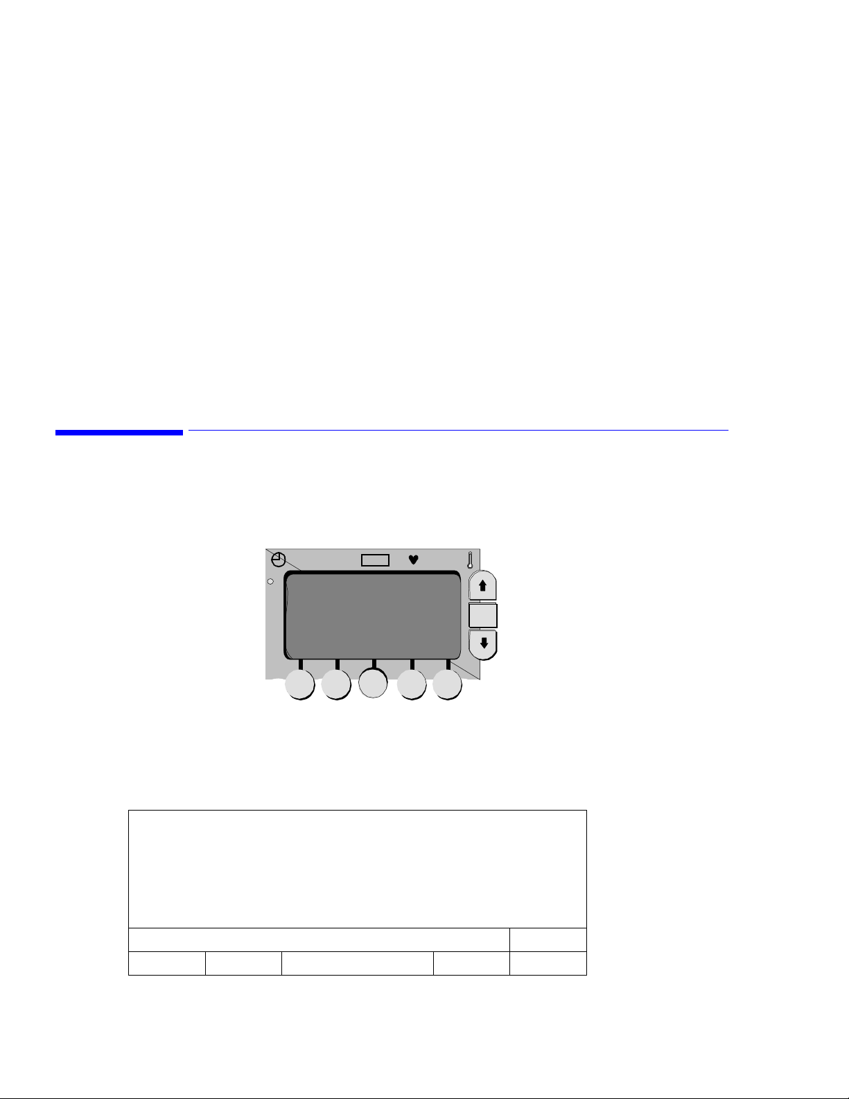
Line List Display
The Line List display is the first screen to appear when the self-test process is complete.
7/9 ID: MARK WILLIS 123745
11:03 120/80 (93) 83 98 98.6
7/9: ID: Unknown?
11:10 120/85 (98) 75 98 98.4
Sys/Di a MAP
LCD
Soft keys
SpO
2
Up button
OK
OK button
Down button
ALARMS CUFF 5 SYSTEM PRINT ID
3-2 Operating Your Monitor
11:06
Page 19

The Line List display shown above is an example of the data that typically appears in the display. It
includes the following information:
• The date (7/9), followed by the patient name and ID. If patient information has not been entered,
• The time at which the vital signs for the specified patient were recorded (11:03).
• The vital signs for the specified patient.
• The cuff interval has been set at 5 minutes.
Any parameters that exceed upper or lower alarm limits are displayed in a box. A question mark (?) next to
the NIBP or SpO
Press the Up or Down button to step through the information in the Line List screen. You can also press and
hold the Up or Down button to quickly scroll through the Line List information.
Note—
not display the newly saved listing. If historical information is left on the screen for more than 30 seconds,
and no buttons are pressed, the screen will revert to the latest information.
Soft Keys
The soft keys are used to select settings that you want to review or change. Pressing one of these soft keys
yields more information about the setting that appears in the box above the selected key, and the screen will
change accordingly.
Saving Data
Unknown? is displayed.
reading indicates patient movement.
2
If you are viewing historical information when the monitor saves a listing to memory, the view will
After using the soft keys to display a secondary screen, you can use the OK button to move the cursor
through the settings on the screen. Use the Up and Down buttons to increase or decrease values that are
highlighted or to toggle between two settings.
Saving Data
The monitor automatically saves information in the Line List memory when:
• A blood pressure measurement is complete.
• An alarm limit is violated.
• A temperature measurement is complete.
• A user-specified interval for storing data has occurred. See the next section, Changing the Save Rate.
• The first SpO
If parameters are being measured concurrently, they will be saved to the Line List at the end of the longest
running measurement.
The Line List memory can save up to 400 lines of data. If the memory contains 400 lines and an additional
measurement is taken, the memory removes the oldest listing and adds the current one.
Data is saved automatically when the unit is turned off. When you turn the monitor back on, the entire Line
Listing will again be available.
Changing the Save Rate
The VS1 monitor automatically saves data, as described in the previous section. You can also choose to
save data at a rate not related to the cycles described above. To change the rate at which data is saved, open
the System Settings screen and change the value of the Line List Input setting
measurement is received.
2
.
Operating Your Monitor
3-3
Page 20

Clearing Data from Memory
Clearing Data from Memory
To clear all data from memory, follow these steps:
Note—
Data deleted from the Line List memory cannot be retrieved.
Step Action
1 From the Line List display, press the System soft key. The System Settings screen appears.
2 Using the OK button, move the cursor to the Line List Memory selection. The Clear option is highlighted.
3 Press and hold the Delete List soft key for three seconds. The monitor will beep three times while the
button is being pressed.
Changing the System Date and Time
The date is displayed as month, day, and year; the time is in 24-hour military time. To change the date and
time:
Step Action
1 From the Line List display, press the System soft key. The System Settings screen appears.
2 Using the OK button, move the cursor to the date or time field you want to change.
3 Use the Up or Down buttons to change the values.
4 To save your changes, press the Save → Main soft key.
3-4 Operating Your Monitor
Page 21

Entering Patient ID Information
This chapter describes how to enter patient IDs in the VS1 monitor.
You do not have to enter an ID to start a measurement; however, if a measurement is started without a
patient ID, the monitor identifies the patient as "Unknown." Also, when you enter an ID, either manually or
using the bar code scanner, the next set of measurements are assigned to the last ID entered. You cannot
enter IDs for later use.
To ensure that all measurements are recorded under the same ID during spot check measurements, you
must follow this sequence of steps:
4
1. Place the SpO
2. Apply the NIBP cuff and initiate a measurement cycle.
The Temperature measurement can be taken any time during the cuff measurement cycle. As soon as all
measurements are complete, all the data is written to the patient’s record
Caution If cuff intervals or Temperature Monitoring mode are in use, or if the SpO
the same patient for longer than 5 minutes, the monitor assumes that all measurements taken during
that time belong to the same patient and places those values in memory under that patient ID.
If no cuff intervals are set and the SpO
been entered), as additional measurements are taken, the monitor assumes the vital signs are for a
new patient and the values are saved to an "Unknown" patient ID.
probe on the patient’s finger.
2
sensor is not kept on the patient (or if no ID information has
2
Using the Bar Code Scanner to Enter Patient IDs
The optional bar code scanner provides a quick way to enter patient ID information in the VS1 monitor.
Step Action
1 If you have not already done so, connect the scanner to the monitor, as described in Setting Up the
Monitor on page 2-1. Turn the monitor on.
2 Pull the scanner’s trigger and, with the scanner approximately 6 inches from the patient’s wrist, aim the
red scanning light at the patient’s bar code.
sensor is connected to
2
As the unit beeps, the ID code is recorded into memory.
3 Verify that the ID displayed on the LCD screen matches the ID on the patient’s wrist, then press the Save
→ Main soft key.
4 Begin measuring the patient’s vital signs. The measurements are then assigned to the ID you just scanned
into memory.
Note—
You must begin measurements within 30 seconds of entering the patient ID to ensure that the
measurements are assigned to the ID you entered.
Entering Patient ID Information 4-1
Page 22

Entering Patient IDs Manually
Entering Patient IDs Manually
If you do not have a bar code scanner, you can enter patient ID information manually. In the Select Patient
ID screen you can enter alphabetic and numeric characters.
To manually enter patient ID information:
Step Action
1 In the Line List display, press the ID soft key.
2 Press the New Pat soft key. The Select Patient ID screen appears.
3 To enter letters, press the ABC... soft key; to enter numbers, press the 123... soft key.
4 Use the Up and Down buttons to scroll through the list of characters.
5 Press the OK button to accept a letter or number and move the cursor to the next space.
Note: Press the Back Space soft key to clear the last character you entered; press the Prev Screen soft key
to erase the entire entry and return to the Select ID screen.
6 After you enter all patient ID information, press the Save->Main soft key. The Patient ID Confirmation
screen appears.
7 Review the information in the screen.
• If the information is correct, press the Save->Main soft key to save the entry and return to the Line
List display.
• If the information is not correct, press the Prev. Screen soft key to return to the Patient ID Input
screen. Make the corrections and press the Save->Main soft key.
8 If you take measurements within 30 seconds of saving the patient ID, the measurements are saved under
the patient ID you just created.
Note—
If you do not take a measurement within 30 seconds, the patient ID will not be saved.
Adding Measurements to an Existing Patient Record
To add measurements to the record of a patient already entered in the system or to view the records for an
existing patient, use the following procedure.
Step Action
1 From the Line List display, press the ID soft key. The Select ID screen appears.
2 Press the Up button until the desired patient ID appears.
3 If you want to verify that the selected patient is the one you are looking for, press the View Pat soft key.
The screen displays the four most recent measurements for the selected patient.
4Press the Save → Main soft key. The next series of measurements will be assigned to the selected
patient ID.
4-2 Entering Patient ID Information
Page 23
This chapter describes how to use the VS1 monitor to check a patient’s blood pressure. You can take a
single, non-invasive blood pressure (NIBP) reading or monitor blood pressure continuously.
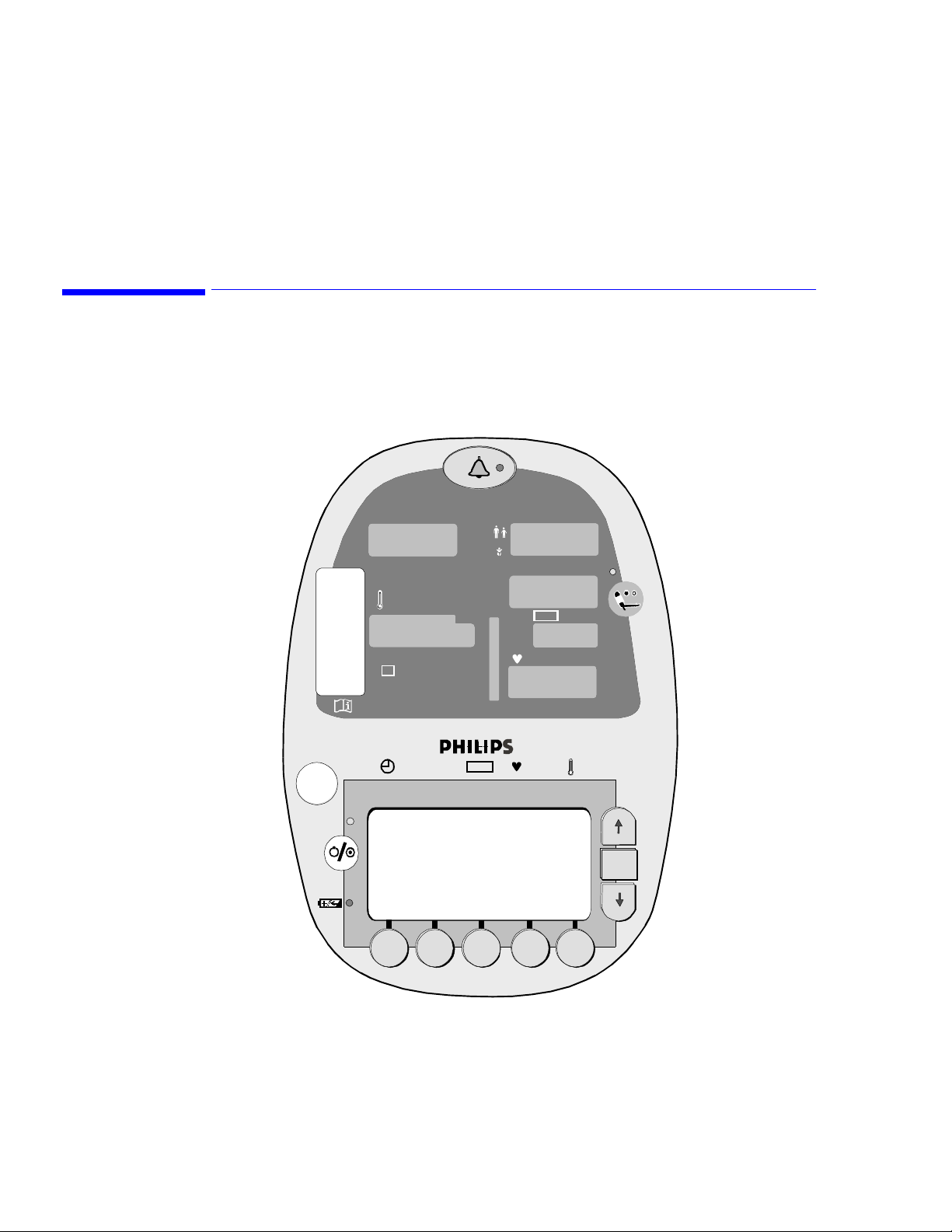
Blood Pressure Controls
Cuff Mode Indicator (LED)
5
Monitoring Blood Pressure
BP Measurement LEDs
for Systolic (Sys),
Diastolic (Dia)
and Mean (MAP)
BP Unit of
Measure
SpO
2
º
C
M
%
º
F
Sys/ Dia M AP
Sys
Dia
MAP
SpO
kpa mmhg
2
bpm
OK
BP Measurement in
Progress Indicator (LED)
Cuff Start/Stop
Button
VS
1
• Cuff Mode Indicator: A yellow LED indicates the mode of operation for the NIBP parameter:
Adult/Pediatric or Neonatal.
• BP Measurement LEDs: Large, yellow LEDs show the Systolic, Diastolic, and Mean Arterial blood
pressures. The cuff pressure is shown in the Mean Arterial Pressure (MAP) window during the
measurement cycle and final MAP values appear after deflation.
• BP Unit of Measure Indicator: Yellow LED identifies the selected unit of measure: mmHg or kPa.
• BP Measurement in Progress Indicator: When lit, this green LED indicates that a blood pressure
measurement cycle is in progress. There may be a slight delay (up to 30 seconds) between the
indicator lighting and the beginning of cuff inflation.
• Cuff Start/Stop Button: When pressed, this button initiates a cuff inflation or stops a blood pressure
measurement cycle already in progress and deflates the cuff.
Monitoring Blood Pressure 5-1
Page 24

NIBP Safety Information
NIBP Safety Information
Warning The monitor cannot operate effectively on patients who are experiencing convulsions or tremors.
If the NIBP measurement is unsuccessful or when there are doubts about measurement values, assess
the patient’s condition immediately. The patient’s condition may have deteriorated to the point where
measurement limits are exceeded. If values appear questionable, it is the clinician’s responsibility to
repeat the measurements.
Inaccurate measurements can be caused by:
• Incorrect cuff applications or use, such as placing the cuff too loosely on the patient, using the
incorrect cuff size, not placing the cuff at the same level as the heart, or placing the cuff over
thick clothing or a rolled up sleeve
• A leak in the cuff or tubing
• Excessive patient motion, including CPR and bed movement
• Serious episodes of shock, hypotension, or decreased body temperature
• Frequent episodes of arrhythmia
The monitor displays results of the last blood pressure measurement until another measurement is
completed. If a patient’s condition changes during the time interval between measurements, the
monitor does not detect the change or indicate an alarm condition.
Sometimes, electrical signals at the heart do not produce a peripheral pulse. If a patient’s beat-to-beat
pulse amplitude varies significantly (for example, pulsus alternans, atrial fibrillation, rapid-cycling
artificial ventilator), blood pressure and pulse rate readings can be erratic and an alternate measuring
method should be used for confirmation.
A patient’s vital signs can vary dramatically during administration of agents affecting the
cardiovascular system, such as those used to raise or lower blood pressure or raise or lower heart rate.
Ensure that heavy objects are not placed on the tubing. Avoid crimping or excessive bending, twisting,
or entangling the tubes.
Connecting the NIBP Cuff and Hose
Warning—Use only recommended Philips blood pressure tubing and cuffs. Using other cuffs or
tubing can result in inaccuracies.
Connect the appropriate hose to the cuff hose connector on the back of the unit. See Chapter2, Setting Up
the Monitor
Select the appropriate sized NIBP cuff and attach it to the hose. Sizes range from neonatal through large
adult and thigh.
Smart Inflation Feature
The VS1 monitor provides a Smart Inflation feature that inflates the cuff to a level based on a patient’s
individual requirements. The monitor automatically inflates the cuff to a pressure above arterial occlusion.
Most monitors inflate to 180 mmHg (
be uncomfortable. The Smart Inflation feature monitors blood pressure during inflation, and stops inflating
when necessary, not at a preset pressure.
5-2 Monitoring Blood Pressure
23.9 kPa) and then deflate. For some patients, that level of inflation can
Page 25
If for some reason the monitor does not detect arterial occlusion, it will inflate to the value specified in the
Initial Inflation Pressure setting, which is described below.
Note—
If a patient is moving, shaking, or agitated during a blood pressure measurement, the Smart
Inflation feature might interpret the movement as a pulse. If this occurs, the cuff could potentially inflate to
a pressure higher than 180 mmHg (23.9 kPa). If your patient cannot remain still, Philips recommends that
you disable the Smart Inflation feature. To disable Smart Inflation, press the System soft key, and then press
the Cuff Option soft key. Use the OK button to move the cursor to the Smart Inflation choice and uncheck
the X. When Smart Inflation is disabled, the monitor will not inflate any higher than the value specified in
the Initial Inflation Pressure setting.
Specifying Cuff Settings
Use the Cuff Settings screen to specify the overall parameters of the NIBP cuff measurements. The cuff
pressure is shown in the mean arterial pressure (MAP) window during the measurement cycle.
MEASUREMENT MODE: ADULT/PEDI
INIT INFLATION PRESSURE: 180 mmHg
Specifying Cuff Settings
[X] BP UPON ALARM
[X] SMART CLOCK
[X] SMART INFLATION
SYSTEM
SCREEN
To display the Cuff Settings screen and change the cuff setting values:
Step Action
1 From the Line List display, press the System soft key. The System Settings screen appears.
2 From the System Settings screen, press the Cuff Option soft key.
3 Use the OK button to select the cuff setting you want to change. The cuff settings are described below.
4 Use the Up or Down button to change the value of a selected setting.
5 To save your changes, press either the System Screen soft key or the Save → Main soft key. If you press
the System Screen soft key, the settings are saved and the System screen appears. If you press the Save →
Main soft key, the settings are saved and the Line List display appears.
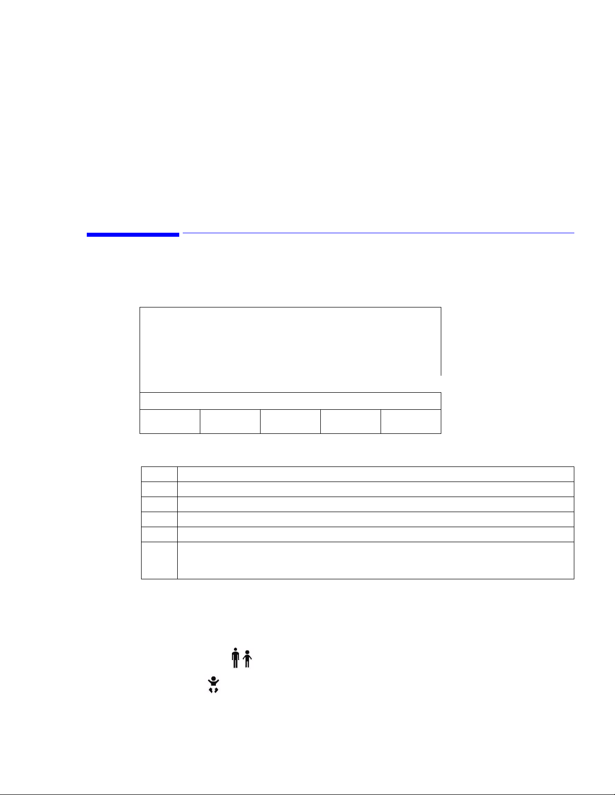
Selecting a Measurement Mode
The Measurement Mode has two settings — Adult/Pediatric and Neonatal. After you select a mode and
save it, the Cuff Mode Indicator light on the front of the monitor displays the currently selected mode:
11:06
SAVE
->MAIN
Adult/Pediatric
Neonatal
Monitoring Blood Pressure
5-3
Page 26

Placing the Cuff
Specifying an Initial Inflation Value
Select an Initial Inflation Pressure between 120 mmHg and 240 mmHg for Adult/Pediatric patients and
between 80 mmHg and 140 mmHg for Neonatal patients. Inflation values are defined in increments of 20.
Settings are saved when the monitor is turned off and become the default when the monitor is powered up.
Enabling the BP Alarm Option
When the BP Upon Alarm option is activated, the monitor will automatically take a second blood pressure
measurement if an alarm limit violation occurs. Use the Up and Down buttons to change the setting.
Enabling Smart Clock for Interval NIBP Readings
The Smart Clock setting allows you to specify that the interval NIBP readings occur at a more logical point
in time. For example, if a 15-minute interval has been set, and the initial measurement is taken at 11:56, the
next "normal" interval would be 12:11. The Smart Clock feature initiates the second measurement at 12:00,
then 12:15, then 12:30, and so on. Use the Up and Down buttons to change the setting.
For information on changing the NIBP intervals, see Continuous NIBP Monitoring on page 5-5.
Placing the Cuff
Warning Inspect the application site regularly to ensure skin quality and inspect the extremity of the cuffed
limb for normal color, warmth and sensitivity. If the skin quality changes, or if the extremity
circulation is being affected, move the cuff to another site or stop the blood pressure measurements
immediately. Check more frequently when making automatic or STAT measurements.
Do not place the cuff on an extremity being used for intravenous infusion or any area where
circulation is compromised or has the potential to be compromised.
Do not apply the blood pressure cuff to the same extremity as the one to which an SpO
attached because the cuff inflation disrupts SpO
Do not apply the cuff to the same arm where IV or blood transfusions are connected.
Measure the patient’s limb and select the proper cuff size. As a general rule, cuff width should span
approximately two-thirds of the distance between the patient’s elbow and shoulder.
A listing of all NIBP cuffs is in Chapter 12, “Accessory List.” Follow the NIBP Cuff’s Directions for Use
when applying the cuff to the arm and thigh.
For neonatal NIBP measurements, make sure the Neonatal measurement mode is selected in the Cuff
Setting screen.
Warning—Inaccurate measurements can occur if the neonate’s systolic blood pressure is over 130 mmHg
(17.3 kPa), due to the 150 – 155 mmHg (19.9 – 20.6 kPa) maximum inflation pressure of the monitor in
Neonatal mode.
monitoring and leads to nuisance alarms.
2
sensor is
2
5-4 Monitoring Blood Pressure
Page 27
Initiating a Single NIBP Measurement
To take a single NIBP reading:
Step Action
1 Enter a new patient ID or select a previously saved patient ID. If you choose not to enter an ID, the
measurements will be assigned to an "Unknown" patient ID.
2 Verify that the correct NIBP mode is selected: Adult/Pediatric or Neonatal.
3 Choose the appropriate cuff and place it on the patient.
4 Press the Cuff Start/Stop button. When the measurement is complete, the Systolic, Diastolic, and Mean
Arterial Pressure values appear in their corresponding LEDs.
Continuous NIBP Monitoring
The VS1 monitor can be used to continually measure a patient’s blood pressure at specified intervals. You
can also create a cuff interval program that measures blood pressure at predetermined times and in
predefined intervals.
Initiating a Single NIBP Measurement
Note—
In Adult mode, the VS1 monitor will sound an alarm at a systolic pressure below 70 mmHg (9.3
kPa), even if a lower limit is set. Neither the feature nor the alarm can be overridden. The range remains
adjustable for use in the Neonatal mode, where lower limits can be set.
Selecting a Cuff Interval
The Cuff Interval option initiates a blood pressure reading every n minutes. From the Cuff Interval screen,
you can select any of the following intervals: OFF, STAT, 1, 2, 2.5, 3, 5, 10, 15, 20, 30, 60, 90, 120, or180
minutes.
CURRENT ID:
MIKE WALLACE, 123458
INTERVAL: 2 MIN
PREV
SCREEN
Note—
If you select an interval of 1 minute, after 12 measurements, the monitor automatically changes the
interval measurement to 5 minutes.
To change the cuff interval value:
Step Action
1 From the Line List display, press the Cuff soft key. The Cuff Interval screen appears. The currently
STOP
PROGRAM
selected cuff interval is displayed.
11:06
STAT SAVE
->MAIN
Monitoring Blood Pressure
5-5
Page 28

Continuous NIBP Monitoring
Step Action
2 Press the Up or Down buttons to change the current interval.
3Press the Save → Main soft key to save the interval you selected and return to the Line List display. The
interval measurement begins.
You can activate continuous blood pressure measurements from the Cuff Interval screen by pressing the
STAT soft key. Measurements are taken for five minutes. After five minutes, the monitor automatically
reverts to five-minute intervals.
Note—
When STAT is specified, a rapid estimation of systolic blood pressure is displayed upon second and
subsequent blood pressure measurements. One beep sounds and a quick estimated systolic value appears.
When the measurement is complete, two beeps sound and the actual blood pressure values are displayed.
To stop a cuff interval that is in progress, press the Cuff Start/Stop button. When the continuous
measurements are interrupted in this manner, the word "STAT" appears in reverse video on the LCD screen
and the measurements cease.
Warning—Do not use STAT mode when using a thigh cuff to monitor NIBP. Use of this mode causes a
loss-of-monitoring alarm and shuts down all monitor functionality.
Selecting a Cuff Interval Program
You can create up to five different cuff interval programs that measure blood pressure at predetermined
times and in predefined intervals. Four of the timed interval programs (A, B, C, and D) can be configured to
your own unit-specific protocols. Program E is pre-configured to a commonly used protocol for training
purposes, but it can be modified by following the steps listed below.
Note—
Resetting factory defaults (in the Service Screen mode) erases all user-designed cuff programs and
resets program E to the factory default values.
To display or edit one of the timed interval programs:
Step Action
1 From the Line List display, press the Cuff soft key. The Cuff Interval screen appears. The currently
selected cuff interval is displayed.
2 Press the Down button past the 1 minute interval until you see the program — A, B, C, D, or E — that
you want to review or modify.
3 Press the View/Modify soft key. The selected program appears on the LCD screen, as seen below.
4 Use the OK button to move between fields and use the Up and Down buttons to edit the values.
5Press the Save
Press the Prev Screen soft key to discard changes and return to the Cuff Interval screen.
→ Main soft key to begin the selected interval program and return to the Line List display.
5-6 Monitoring Blood Pressure
Page 29

Continuous NIBP Monitoring
Sample Program
When you open programs A, B, C, or D for the first time, all of the program fields are blank. You can
specify the length of each measurement period and the desired cuff interval for each measurement period,
as seen in the following example.
INTERVAL PROGRAM A
RUN TIME: --
TIME (HH:MM) INTERVAL
START 1:00 5 MIN
1:00 2:00 15 MIN
2:00 4:00 30 MIN
4:00 6:00 60 MIN
6:00 -- 90 MIN
11:06
PREV
SCREEN
SAVE
->MAIN
In this example, Interval Program A has five defined measurement periods. The first measurement period is
one hour long (Start – 1:00) during which NIBP measurements will be taken every 5 minutes. The second
measurement period is also one hour long (1:00 – 2:00). During the second measurement period, NIBP
measurements will occur every 15 minutes.
Run Time is not defined in Interval Program A. This particular program will run indefinitely because the
last measurement period contains a "--" to indicate that measurements should continue until explicitly
stopped by the user. If a program contains specific beginning and ending times, the total duration of the
program will appear in the Run Time field at the top of the screen.
Valid Values
Start times and end times can be any five-minute increment between 00:05 and 12:00. End times can also
be "—" which indicates that the test will run indefinitely.
Up to five measurement periods can be defined in one program.
The possible selections for this value are: "—" (this selection indicates that this period will continue for
eternity) and 0:05 – 12:00 (a time selection, in five minute increments).
The Cuff Interval value can be any of the following: OFF, STAT, 1, 2, 2.5, 3, 5, 10, 15, 20, 30, 60, 90, 120,
and 180 minutes. The selected interval must be shorter than the measurement period.
If an Interval program is in progress when a user enters the screen, the cursor will identify the current point
in time in that program. If no program is running, the cursor will appear next to the first time frame. You
cannot make changes while a program is in progress.
Monitoring Blood Pressure
5-7
Page 30

Continuous NIBP Monitoring
While the program is running, the letter identifying the program and a number identifying the current cuff
interval appears on the Line List display under the word “Cuff.” For example, “A-5” indicates that program
A is running and a cuff interval of 5 minutes is in process.
Stopping Interval Measurements
To inactivate all interval settings, press the Stop Program soft key in the Cuff Interval screen. The Interval
setting changes to Off.
5-8 Monitoring Blood Pressure
Page 31

This chapter describes how to monitor temperature with the VS1 monitor. You can take a single
temperature reading or monitor temperature continuously.
Temperature Controls
Temperature Probe Cover
Box Receptacle
SpO
Monitoring Temperature
2
Sys
6
Temperature
Measurement LED
Temperature
Units of Measure
Temperature Mode
Indicator (LED)
Temperature
Probe Well
º
C
M
%
º
F
Sys/ Dia M AP
VS
kpa mmhg
Dia
MAP
bpm
SpO
2
OK
1
• Temperature probe cover box receptacle: Insert the box of probe covers here.
• Temperature measurement LED: Large, green LED displays the current temperature
measurement.
o
• Temperature units of measure indicator: Indicates the currently selected units of measure —
o
F — for the temperature measurement.
C or
• Temperature mode indicator: If the green M is lit, the monitor is in Monitoring mode. If the LED
is not lit, the monitor is in Predictive mode.
• Temperature probe well: The temperature probe is inserted here when not in use. Withdrawing the
probe initiates a temperature measurement, replacing it stops a measurement.
Monitoring Temperature 6-1
Page 32

Temperature Safety Information
Temperature Safety Information
Warning Use only Alaris
®
Turbo*Temp® probes with your monitor.
Do not use the thermometer if you see any signs of damage to the probe.
When performing defib, sync or electrosurgery, there is a potential for signal corruption.
If a temperature reading is unusually high or low, confirm the reading using another temperature
measuring device before beginning any treatment.
Note—
For oral temperature measurements, use the blue probe; for rectal measurements, use the red probe.
Setting the Measurement Mode
The VS1 monitor provides two temperature measurement modes:
• Predictive mode. In Predictive mode, the monitor measures the patient’s temperature for
approximately 7 seconds, and then displays the final measurement and sounds a tone signifying
completion.
• Monitoring mode. In Monitoring mode, the monitor measures the patient’s temperature
continuously and displays the temperature constantly in large, green numbers (as long as the probe is
in contact with the patient).
You can change the mode in the Measurement Mode screen.
MEASUREMENT MODE: PREDICTIVE
To open the Measurement Mode screen and change the temperature mode:
Step Action
1 From the Line List display, press the System soft key. The System Settings screen appears.
2 In the System Settings screen, press the Temp Option soft key. The Measurement Mode screen appears.
3 Use the Up or Down button to select Predictive or Monitoring mode.
4 To save your changes, press either the System Screen soft key or the Save → Main soft key. If you press
the System Screen soft key, the settings are saved and the System Settings screen appears. If you press the
Save → Main soft key, the settings are saved and the Line List display appears.
Temperature Mode LED
To determine which mode is active, look at the Temperature Mode Indicator LED (the letter M) on the
front of the monitor. If the indicator is lit, Monitoring mode is selected; if the indicator is not lit, Predictive
mode is selected.
6-2 Monitoring Temperature
SYSTEM
SCREEN
11:06
SAVE
->MAIN
Page 33

Selecting a Probe
For oral temperature measurements, use the blue probe; for rectal, use the red probe. See Chapter12,
Accessory List, for a complete list of temperature accessories.
Be sure to review the instructions that come with the temperature probe.
Taking a Single Temperature Measurement
When not in use, the temperature probe should be inserted in the temperature probe well. Withdrawing the
probe initiates a temperature measurement, replacing it stops a measurement.
To take a single temperature measurement:
Step Action
1 Make sure Predictive mode is the active mode. If the Temperature Mode Indicator LED is not lit, the
monitor is in Predictive mode. For information on changing this setting, see Setting the Measurement
Mode on page 6-2.
2 Insert the appropriate probe — oral or rectal — firmly into the probe cover. Make sure the cover is on
securely.
Selecting a Probe
Caution—Failure to firmly install the probe cover may cause the cover to become loose or disengaged
during use. Be careful not to press the probe ejection button (where the cord exits the probe) during use.
3 Follow the manufacturer’s instructions for placing the probe. Hold the probe during the entire temperature
measurement process and keep the probe tip in contact with tissue at all times. Do not allow the patient to
reposition or hold the probe.
A beep sounds when the measurement is complete, and the temperature appears in large, green numbers.
The value will remain on the screen for 5 minutes or until another temperature is initiated.
4 When the measurement is complete, hold the probe as you would a syringe and press the probe eject
button at the base of the probe to release the used cover into a waste container.
5 Return the probe into the probe well to prepare for the next measurement.
While the patient’s temperature is being taken, the Temperature Measurement LED shows a moving
pinwheel, indicating tissue contact. If contact is broken, the pinwheel stops moving until contact is
reestablished.
Note—
A long delay from the time the probe is removed from the temperature probe well until it makes
contact with the patient’s tissues may cause a break in the measurement cycle, causing the monitor to
switch from Predictive mode to Monitoring mode. If this occurs, eject the probe cover, insert the probe
back into the temperature probe well, and begin the process again.
Note—
If the temperature of the probe tip is higher than 92o F (33.3o C) when removed from the
temperature probe well, the monitor cannot operate in Predictive mode. In such a case, the monitor will
automatically switch to Monitoring mode, and may require 3 minutes or longer to display a stable
temperature reading.
Monitoring Temperature
6-3
Page 34

Measuring Temperature Continuously
Measuring Temperature Continuously
To measure a patient’s temperature continuously:
Step Action
1 Make sure Monitoring mode is the active mode. If the Temperature Mode Indicator LED (the letter M) is
lit, the monitor is in Monitoring mode. For information on changing this setting, see Setting the
Measurement Mode.
2 Remove the oral probe from the probe well and attach a probe cover.
Caution—Failure to firmly install the probe cover may cause the cover to become loose or disengaged
during use. Be careful not to press the probe ejection button (where the cord exits the probe) during use.
3 Place the probe tip in the sublingual pocket of the patient’s mouth. Hold the probe during the entire
temperature measurement process and keep the probe tip in contact with tissue at all times.
Observe the display until the value stops changing (3 – 5 minutes), indicating the final temperature.
Unlike Predictive mode, there is no audible signal to indicate a final temperature reading in Monitoring
mode.
4 When the measurement is complete, hold the probe as you would a syringe and press the probe eject
button at the base of the probe to release the used cover into a waste container.
5 Return the probe into the probe well to prepare for the next measurement.
6-4 Monitoring Temperature
Page 35

Monitoring SpO2 and Pulse Rate
This chapter describes how to use the VS1 monitor to check a patient’s SpO2 and pulse rate.
SpO2 and Pulse Controls
SpO2 Measurement LED
SpO
7
2
Sys
º
C
M
%
º
F
Sys/Dia MAP
VS
kpa mmhg
Dia
MAP
SpO
bpm
2
Pulse Rate
Measurement LED
Pulse Level
Indicator
OK
1
• SpO2 Measurement: Red LED displays the current oxygen saturation measurement (% saturation
value).
• Pulse Rate Measurement: A red LED displays the current pulse rate in beats per minute (bpm).
• Pulse Level Indicator: This eight-segment LED bar indicates the strength of the pulse signal. The
pulse strength can be derived from the SpO
measurement or the NIBP measurement. The SpO
2
2
measurement is triggered by each pulse. The blood pressure pulse measurement is triggered by the
cuff cycle and remains on the monitor screen until the next cuff cycle.
Monitoring SpO2 and Pulse Rate 7-1
Page 36

SpO2 Safety Information
SpO2 Safety Information
Warning Do not:
• Use damaged sensors
• Use a sensor with exposed optical components
• Immerse sensor completely in water, solvents, or cleaning solutions because the connectors and
most sensors are not waterproof.
Inspect the application site every two to three hours to ensure skin quality and correct optical
alignment. If the skin quality changes, move the sensor to another site. CHANGE THE
APPLICATION SITE AT LEAST EVERY FOUR HOURS.
Using an SpO
sensor during MR imaging can cause severe burns. Minimize this risk by positioning
2
the cable so that no inductive loops are formed. If the sensor does not appear to be operating
properly, remove it immediately from the patient.
Sterilization is not recommended for this monitor, related products, accessories or supplies unless
otherwise indicated in the Instructions for Use that accompany the accessories and supplies.
Inaccurate measurements can be caused by the following:
• Incorrect sensor application or use
• Significant levels of dysfunctional hemoglobins (such as carboxyhemoglobin or methemoglobin)
• Injected dyes, such as methylene blue, or intravascular dyshemoglobins, such as
methemoglobin and carboxyhemoglobin
• Exposure to excessive illumination, such as surgical lamps (especially ones with a xenon light
source), bilirubin lamps, fluorescent lights, infrared heating lamps, or direct sunlight)
• Excessive patient movement
• High-frequency electrosurgical interference and defibrillators
• Venous pulsations
• Placement of a sensor on an extremity with a blood pressure cuff, arterial catheter, or
intravascular line
• The patient has hypotension, severe vasoconstriction, severe anemia, or hypothermia
• There is arterial occlusion proximal to the sensor
• The patient is in cardiac arrest or is in shock
Loss of pulse signal can occur in any of the following situations:
• The sensor is too tight
• There is excessive illuminations from light sources such as a surgical lamp, a bilirubin lamp, or
sunlight
• The blood pressure cuff is inflated on the same extremity as the one to which an SpO
sensor is
2
attached
Caution Use only Philips recommended sensor extension cables and specified SpO2 sensors with the monitor.
Other sensors can cause inaccurate readings. Philips’ warranty agreement does not apply to defects
arising from improper use.
Do not use OxiCliq disposable sensors in a high humidity environment, such as in the presence of
fluids, which may contaminate sensor and electrical connections causing unreliable or intermittent
measurements.
7-2 Monitoring SpO2 and Pulse Rate
Page 37

Do not use disposable sensors on patients who have a known allergic reaction to the adhesive.
Position the sensor cable and connector away from power cables, to avoid electrical interference.
Do not use the ear transducer on patients with a small ear lobe as incorrect measurements may
result.
If you measure SpO
anymore and no new SpO
Selecting a Sensor
The VS1 monitor uses Nellcor® OxiMax® sensors. Philips recommends that you use only Nellcor sensors
with the VS1 monitor. To obtain accurate measurements, you must select the appropriate sensor for each
patient. The following table lists the sensors and their recommended usage.
Sensor Name Recommended Usage
Dura-Sensor
DS-100A
MAX-A
MAX-AL
MAX-P
MAX-I
MAX-N
MAX-R
MAX-FAST
Dura-Y
®
®
®
®
®
®
®
®
®
D-YS Reusable multisite sensor. For patients who weigh more than 2 lbs (1 kg). If used with the D-
Selecting a Sensor
on a limb that has an inflated NIBP cuff, the arterial blood isn’t pulsing
2
value or pulse rate can be detected during that time.
2
Reusable sensor. Use on adults weighing over 88 lbs (40kg).
Disposable adhesive sensor. Use on adults weighing over 66 lbs (30kg).
Disposable adhesive sensor. Same as MAX-A sensor, but has a longer cable (36").
Disposable adhesive sensor. For pediatric patients who weigh 22 – 110 lbs (10 – 50 kg).
Disposable adhesive sensor. Use on infants weighing from 7 to 44 lbs (3 – 20 kg).
Disposable adhesive sensor. Use on neonates weighing less than 7 lbs (3 kg). Use on the leg or
arm. Can also be used on the forearm of an adult weighing over 88 lbs (40 kg).
Disposable adhesive nasal sensor. Use on adults weighing over 110 lbs (50 kg).
Disposable adhesive forehead sensor. Use on adults weighing over 88 lbs (40kg).
YSE ear clip, can only be used on patients who weigh more than 66 lbs (30 kg).
Warning—Carefully read the description, instructions, warnings, cautions, and specifications provided with
the Nellcor sensors.
Placing the Reusable Sensor
The Dura-Sensor DS-100A sensor is for adult patients who weigh more than 88 lbs (40 kg). Put the DS100A on the forefinger, placing the finger far enough into the sensor that the nail comes in contact with the
back. Make sure that the clamping strength of the probe is not so tight that perfusion is affected.
Warning The monitoring site must be checked every four hours and the sensor repositioned.
The nasal OxiMax sensor cannot be reused.
If the finger is put too far into the sensor, the fingertip may be compressed and may cause necrosis.
Never use surgical tape to secure the probe in place.
Be alert to low thermal burns on peripheral circulation disorder patients who are monitored
continuously for extended periods.
Monitoring SpO2 and Pulse Rate
7-3
Page 38

Placing the Disposable Sensor
Placing the Disposable Sensor
Remove the protective film on the adhesive surface of the sensor. If the OxiMax is used on the finger, make
sure the wire is located over the nail.
To ensure an accurate reading, wrap the sensor over the finger so that the light source and the photo
detector are in the same line.
Warning Be sure to read the OxiMax instructions before using the sensors.
Apply to a clean, dry site.
Do not apply additional tape over the sensor. Using additional tape increases the risk of venous
pulsation, pressure damage at the site, and inaccurate saturation measurements. You can, however,
apply tape over the cable to help prevent the sensor from becoming dislodged.
Check sensor site and circulation distal to the sensor at least every 8 hours and change the sensor as
required.
7-4 Monitoring SpO2 and Pulse Rate
Page 39

The VS1 alarms can be configured to alert you when a measured value exceeds specified high and low
limits. This chapter describes how to set the alarm limits.
Alarm Controls
Alarm Silence Button
SpO
8
Setting Alarms
Alarm Indicator LED
2
Sys
º
C
M
%
º
F
Sys/ Dia M AP
VS
kpa mmhg
Dia
MAP
bpm
SpO
2
OK
1
• Alarm Silence Button: Used to silence an audible alarm for two minutes and activate the alarm
indicator LED. If, after two minutes, a measurement is still outside acceptable limits, the alarm will
reactivate. To silence all alarms for two minutes (whether sounding or not), push and hold the Alarm
Silence button for three seconds.
• Alarm Indicator LED: Indicates the current status of the alarm function. No light indicates no
alarms, a slow flashing light indicates that an alarm has sounded and has been silenced, and a fast
flashing light indicates that all alarms have been silenced.
Setting Alarms 8-1
Page 40

Changing Alarm Limits
The VS1 monitor contains several alarm parameters. High and low values can be set for Systolic, Diastolic,
Mean, Pulse Rate, SpO
limit or falls below the low limit settings, the corresponding LED will flash, a message appears in brackets
on the LCD screen, and, if the audible alarm has been set, the alarm will sound.
To access the Alarms screen, press the Alarms soft key from the Line List display. When the Alarms screen
opens it displays current alarm settings
, and Temperature parameters. When a measured value exceeds the specified high
2
.
Sys/Dia MAP SpO
High 150/90 110 120 OFF 103.5
Low 90/50 70 50 95
PREV
SCREEN
CHANGE
TOL
Changing Alarm Limits
When you open the Alarms screen, the Systolic High alarm limit is highlighted by default. To change focus,
press the OK button until the value you want to change is highlighted. To change the value, press the Up or
Down button, and then press the Save → Main soft key.
The following table lists the supported ranges for each alarm
Parameter Lower Limit Upper Limit
Systolic Off, 20 – 160 mmHg (2.6 – 21.3 kPa) 50 – 240 mmHg (6.6 – 31.9 kPa), Off
Diastolic Off, 20 – 120 mmHg (2.6 – 15.9 kPa) 40 – 180 mmHg (5.3 – 23.9 kPa), Off
Mean Arterial Pressure
(MAP)
Pulse Rate Off, 30 – 295 bpm 35 – 300 bpm, Off
SpO
2
Temperature 80 – 107
Temp.
11:06
SAVE
->MAIN
AUTO
UPDATE
UNDO
CHANGE
2
Off, 20 – 120 mmHg (2.6 – 15.9 kPa) 50 – 200 mmHg (6.6 – 26.6 kPa), Off
Off, 50 – 99 % 51 – 100 %, Off
o
F (26.6 – 42.1 oC), Off
Note—
kPa), even if a lower limit is set. Neither the feature nor the alarm can be overridden. The range remains
adjustable for use in the Neonatal mode, where lower limits can be set.
8-2 Setting Alarms
In Adult mode, the VS1 monitor will sound an alarm at a systolic pressure below 70 mmHg (9.3
Page 41

Setting Patient-Specific Alarm Limits
The Auto Update feature allows you to set alarm limits that are based on an individual patient’s vital signs
measurements. After you take an initial measurement, you can select the Auto Update soft key to adjust the
alarm limits by a specified percentage of the patient’s current vital signs measurements. These percentages
are defined in the Alarm Tolerance screen, as seen in the following illustration.
Setting Patient-Specific Alarm Limits
Sys/Dia MAP SpO
High+%50/50505050OFF
Low -%20/20202020
11:06
PREV.
SCREEN
2
Temp.
SAVE
->MAIN
For example, if a patient’s baseline Systolic measurement is 120 mmHg (15.9 kPa), and you want an alarm
to sound if the Systolic value increases by more than 20%, you can specify the 20% alarm tolerance in the
Alarm Tolerance screen. You then press the Auto Update soft key in the Alarms screen, and if the patient’s
Systolic value exceeds the 20% tolerance (144 mmHg or 19.1 kPa), an alarm will sound.
When you begin measurements on the next patient, you can use the same percentages specified in the
Alarm Tolerance screen or you can modify them.
If you do not use the Auto Update feature, the monitor uses the alarm limit values in the Alarms screen.
To use the Auto Update feature:.
Step Action
1 Begin measurements on a new patient or open an existing patient ID and begin measurements.
2 When the measurements are complete, press the Alarms soft key. The Alarms screen appears, displaying
the current high and low alarm limit values.
3 Press the Change Tol. soft key to review the current alarm tolerances. Change any alarm tolerance values
you want to change and press the Save → Main soft key.
4 Press the Alarms soft key to open the Alarms screen, press the Auto Update soft key, and then press the
Save → Main soft key.
The screen displays the new alarm limits, which are based on the percentages specified in the Alarm
Tolerance screen. The new alarm limits are activated for the next measurement.
Changing Audible Alarm Settings
The audible alarm is a high-pitched tone that sounds at one-second intervals until a new measurement is
taken and the new measurement falls within the alarm limits.
If, for any reason, the monitor is unable to determine the final blood pressure values during a measurement
cycle, a caution code appears in the LCD and the unit beeps two times to announce a new measurement
cycle is about to begin.
Setting Alarms
8-3
Page 42

Changing Audible Alarm Settings
If a critical error occurs (such as loss of internal communication), an error code appears in the LCD and an
audible alarm sounds. This alarm will continue until silenced. See Error and Informational Messages on
page 10-6 for more information.
Adjusting the Volume
You can change the volume on the alarm or the pulse sound. If the pulse volume is set to Off, no pulse tone
will be heard. You cannot turn the alarm volume completely off. The alarm volume should be set at a level
that is appropriate for the environment in which it will be used.
Note—
The Pulse volume setting does not change the pitch of the pulse tone; the pitch is controlled by the
SpO
value.
2
To change the volume of the alarm or the pulse sound:
Step Action
1 From the Line List display, press the System soft key. The System Settings screen appears.
2 Press the OK button until the Alarms or Pulse setting is highlighted.
3 Use the Up and Down buttons to adjust the volume.
4Press the Save → Main soft key to save the volume settings and return to the Line List display.
Silencing the Alarm
When an audible alarm sounds, you can silence the active alarm or you can silence all alarms, as follows:
• To silence the active alarm, press the Alarm Silence button located on the top of the front panel.
alarm will be silent for two minutes and the red Alarm Indicator light will flash slowly.
• To silence the active alarm, as well as all other alarms for two minutes, press and hold the Alarm
Silence button for three seconds.When all alarms have been silenced, the Alarm Indicator light
flashes rapidly.
The
8-4 Setting Alarms
Page 43

This chapter describes how to load the paper into the recorder and how to use the print options to print
different types of vital signs records.
Loading the Paper
To load paper into the recorder:
Step Action
1 Determine which side of the paper is the printable side. Use your fingernail to rub the paper; if the paper
marks, the correct side is up.
2 To make insertion of the paper easier, cut or tear the paper straight across the top. (See Figure A.)
3 Press the Power On/Off switch to turn the power on.
4 Open the printer door on the right side of the monitor and insert the roll of paper so that the end comes
from the back over the top of the roll. (See Figure B.)
5 Pull the paper’s leading edge out about 10 inches and loop it back into the paper slot. Push the paper
toward the back of the recorder until it catches. After it catches, the printer will automatically grab and
feed the paper. (See Figure C.)
6 Once the paper passes the outer edge of the case, close the paper door and select a print format. The
resulting printout will remove any remaining loop in the paper.
9
Recording and Printing Results
Figure A
Tear Straight
Across
Note—
When tearing off the printout, pull the strip up and toward yourself or up and away from yourself.
Printing Automatically
The VS1 monitor can be configured to print a vital signs record each time a blood pressure or temperature
measurement finishes. If measurements are simultaneous or immediately concurrent, the monitor will wait
until the longest measurement is complete before printing.
Figure B
Figure C
A
Figure D
B
A
C
C
B
D
Recording and Printing Results 9-1
Page 44

Printing Only When an Alarm Occurs
Note—
To ensure that all measurements are recorded under the same ID during spot check measurements,
you must follow this sequence of steps: First, place the SpO
NIBP cuff and initiate a measurement. Temperature can be taken any time during the cuff measurement
cycle. As soon as all measurements are complete, all the data is written to the patient’s record.
probe on the patient’s finger, then apply the
2
Use the Print Settings screen to enable the automatic print option
[ ] PRINT UPON ALARM
[ ] VITAL SIGNS PRINT
SYSTEM
SCREEN
.
11:06
SAVE
->MAIN
To configure the monitor to print vital signs records automatically:
Step Action
1 From the Line List display, press the System Settings soft key. The System Settings screen appears.
2 In the System Settings screen, press the Print Option soft key. The Print Settings screen appears.
3 Press the OK button until the Vitals Signs Print option is highlighted.
4 Use the Up or Down button to turn on the option. An X appears inside the brackets when the option is
enabled.
5 To save your changes, press either the System Screen soft key or the Save → Main soft key. If you press
the System Screen soft key, the settings are saved and the System screen appears. If you press the Save →
Main soft key, the settings are saved and the Line List display appears.
The monitor will now print a vital signs record for each patient, after all measurements on that patient are
complete. The Vital Signs print format is used with the automatic print option. See Print Formats on page 93 for an example of the Vital Signs format.
Printing Only When an Alarm Occurs
If you want to configure the monitor to print vital signs only when an alarm violation occurs, select the
Print Upon Alarm option in the Print Settings screen, as seen in the previous section.
The Vital Signs print format is used with the Print Upon Alarm option. See Print Formats on page 9-3 for
an example of the Vital Signs format.
Selecting Additional Print Options
The Print Request screen displays several print options, which are described in the following sections. To
open the Print Request screen, press the Print soft key in the Line List display
9-2 Recording and Printing Results
.
Page 45

Printing Vital Signs for the Current Patient
Use the following procedure to print a patient’s current vital signs:
Step Action
1 Take the patient’s vital signs.
2 In the Line List display, press the Print soft key. The Print Request screen appears.
3 Press the Print Current soft key. The system creates a printout of the patient’s current vital signs in the
Vital Signs Print format.
Printing Vital Signs by Patient ID
To print vital signs for a patient that is not currently displayed on the LCD screen, you must select the
patient ID first.
Step Action
1 In the Line List display, press the Print soft key. The Print Request screen appears.
2 Press the Print Pat soft key. The Patient ID screen appears.
3 Select the ID of the patient whose vital signs you want to print.
4 Press the View Patient soft key to view the measurements.
5 Press the Print soft key to print the measurements. The information is printed out in the Line List format.
The newest data is printed first.
Print Formats
Printing All Currently Displayed Records
To print the vital signs currently displayed on the LCD screen:
Step Action
1 In the Line List display, press the Print soft key. The Print Request screen appears.
2 Press the Print Screen soft key. The system prints all vital signs currently displayed on the LCD screen.
The printout is provided in the Line List format.
3 After the printing is complete, press the Main soft key to return to the Line List display
Printing All Records in Memory
To print all of the records in the line list memory:
Step Action
1 In the Line List display, press the Print soft key. The Print Request screen appears.
2 Press the Print List soft key. The system prints all records in the line list memory, starting with the newest
record. The printout is provided in the Line List format.
3 After the printing is complete, press the Main soft key to return to the Line List display
Print Formats
A printout uses either the Vital Signs print format or the Line List print format, depending on which print
option is selected. These formats are described below.
Recording and Printing Results
9-3
Page 46

Print Formats
Vital Signs Print Format
The following illustration is an example of the Vital Signs print format. This format is used with the Vital
Signs Print option, the Print Upon Alarm option, or when you print vital signs for the current patient.
mmHg
Jon Peters, 123324 5634556
This format includes the following information:
• The patient’s name and ID number
• The current date and time
• Vital signs measurements, plus the following information:
– Any value that violates alarm limits is displayed within a box.
– If a "?" appears next to the NIBP cuff reading or SpO
motion), it will also appear next to the corresponding reading on the printout.
– If the NIBP mode is set to Neonatal, an "N" appears next to the SYS value.
• An oscillometric profile indicates possible problems with the accuracy of the measurement. A normal
oscillometric profile is a bell-shaped curve. An abnormal profile is usually caused by patient
movement, as seen in the following illustration.
0 50 100 150 200
0 50 100 150 200
Normal
Line List Print Format
mmHg
0 50 100 150 200
0 50 100 150 200
Spikes Due to Patient
Movement
mmHg
reading on the LCD (to indicate patient
2
0 50 100 150 200
Missing Oscillations Due
to Arrhythmia or Patient
Movement
mmHg
M/D/Y 19/ 1/2002 14:35
Following is an example of the Line List print format. This format is used when you print all vital signs
records for a specific patient or you choose to print all records in memory.
The Line List printout contains multiple patient records. It contains the same information as the Vital Signs
printout, except that it does not include an oscillometric profile.
9-4 Recording and Printing Results
Page 47

Troubleshooting and Maintenance
This chapter provides troubleshooting and maintenance information. If the unit does not operate properly,
check the guidelines in this chapter before contacting the Philips Response Center or your local Philips
representative.
Warning Should the monitor fail for any reason, follow these procedures immediately:
1. Check the patient’s condition.
2. Read this Troubleshooting section to search for the problem and possible solutions.
3. If the problem remains unsolved:
a. Remove the cuff and probe from the patient.
b. Turn the power off and, if plugged into an AC source, unplug it.
c. Indicate with a sign that the unit is Out of Order.
d. Contact the appropriate personnel for service.
10
Problems with the Monitor
Cannot turn on power to the monitor. Display is blank.
Cause Solution
Cord is unplugged, loose, or
damaged
Battery is discharged Plug the monitor into a hospital-grade AC power outlet and recharge the battery for
Internal AC fuse is bad The AC/DC converter has auto-resetting fuses that can be reset by removing AC
Battery fuse is bad If the unit operates on AC power, but will not function on battery power, the 5A
Cannot turn on power to the monitor. Display comes on and power cycles
Cause Solution
Battery is defective Allow battery to charge for a period of 10 minutes. Then turn on again. Verify that
The unit overheats
Cause Solution
Note: The unit will normally get warm as it charges a fully depleted battery. It will normally start to cool down
after 2 hours of charging.
Airflow to the monitor is
impeded
Check the power input cord connections. When this problem occurs, the Charging
LED will not be lit.
at least 10 minutes. Then turn on again.
power for 30 seconds.
fuse on the battery may be blown. Remove battery from bottom of unit and check
fuse.
the battery voltage is above 6.0 V as the power cycles.
Move the monitor or remove objects that are too close to it.
Troubleshooting and Maintenance 10-1
Page 48

Recorder Problems
Battery power does not last
The monitor is designed to provide a minimum of 4 hours of battery power with spot check measurements taken
every 15 minutes. Philips recommends that the battery be replaced at least once a year to maintain sufficient
battery power.
Monitor does not respond to button press
Cause Solution
Monitor being used
incorrectly.
Unit does not retain settings and continuously displays "Factory Defaults"
The "SYS-Factory Defaults" message displays the first time the unit is powered up after the Factory Defaults
have been initiated. If the unit senses that the saved memory has become corrupt, the unit will initiate a Factory
Default.
Display is not complete or missing segments
Cause Solution
Incorrect model setting Ask your Biomed to reset the model number to the correct value.
Speaker volume is not appropriate
Cause Solution
Incorrect volume setting Select the desired volume setting in the System configuration screen.
Verify that the operator is using the unit correctly.
Recorder Problems
Paper Jams
Cause Solution
Note: If a paper jam occurs, turn the monitor off, remove the AC power, lift up the platen release lever on the left
side of the printer, and slowly pull on the paper to remove it from the printer.
Incorrect paper used Use only Philips recorder paper. If incorrect paper is used, the recorder will jam.
Paper inserted incorrectly Make sure the paper is inserted as described in Chapter 9, Recording and Printing
Recorder does not print
A paper jam occurred Turn off the monitor, remove the AC power, lift up the platen release lever on the
Incorrect model setting Ask your Biomed to reset the model number to the correct value.
Incorrect paper used Use only Philips recorder paper. If incorrect paper is used, the recorder will jam.
Non-thermal paper used If the paper is not thermal paper, it will not print. Use only Philips recorder paper.
Results.
left side of the printer, and slowly pull on the paper to remove it from the printer.
When the power is turned on again, the printer will reset.
10-2 Troubleshooting and Maintenance
Page 49

NIBP Problems
LEDs do not change from "888" to "- - - "
Cause Solution
Incorrect model setting Ask your Biomed to reset the model number to the correct value.
Cuff does not inflate
Cause Solution
Faulty cuff hose connection Check all connections and check hoses for damage or leaks.
Leak in the cuff Check cuff and replace if faulty.
Incorrect cuff mode If the NIBP measurement mode is incorrect for the cuff being used, the cuff will not
Cuff hose kinked Verify that the hose is not kinked or occluded.
NIBP Initializing message appears
Cause Solution
Loss of communication Turn the power off, wait 10 seconds, and then turn the power back on to clear the
Abnormal readings
Cause Solution
Note: If the monitor detects motion, vibrations, or an arrhythmia, a "?" appears to the left of the measurement
values displayed on the LCD.
NIBP Problems
inflate and an alarm will occur.
message.
To verify a suspect measurement value, initiate another measurement, placing your stethoscope under the cuff
and watch the cuff pressure shown in the MAP display. The clinician’s measured values normally fall within 5
mmHg of the monitor’s displayed values.
Vibrations, such as patient
shivering, arrhythmia, or
noises, including bodily
contact or motion, or cardiac
massage during a
measurement
Cuff placement or
positioning
Unreliable NIBP readings
Cause Solution
Cuff placement or
positioning
Cuff/limb not at heart level Place cuff/limb at patient’s heart level.
Unstable blood pressure Check patient for reciprocal pulsations or respiratory alterations.
Patient movement or
anxiousness
Assess the patient’s condition, then start the measurement again.
Verify that the appropriate cuff is selected for the patient and that it is positioned
correctly.
Verify that the appropriate cuff is selected for the patient and that it is positioned
correctly.
Check for patient movement.
Troubleshooting and Maintenance
10-3
Page 50

Temperature Problems
Temperature Problems
No temperature measurement
Cause Solution
Incorrect model setting Ask your Biomed to reset the model number to the correct value.
Disconnected probe or cable Connect probe or replace it if it is defective.
Probe out of well on power-upInsert probe into probe well and try the measurement again.
Defective probe If the "Temp-Probe Disconnected" message appears, the probe is probably
"Temp - Internal Error" shown
Cause Solution
Defective probe If this message appears, the probe is probably defective. Replace the probe. Insert
Unreliable temperature reading
Cause Solution
If any of the following problems occur, you may also notice long temperature measurements times. In addition,
the temperature pinwheel, which indicates tissue contact, may stop moving.
Patient’s mouth was open Ask patient to keep mouth closed during measurement.
Improper probe placement Check the placement of the probe. In Predictive mode, the probe must be placed
LEDs do not change from "888" to "- - - "
Cause Solution
Incorrect model setting Ask your Biomed to reset the model number to the correct value.
defective. Replace the probe. Insert the new probe into, out of, and back into the
probe well to reset the message.
the new probe into, out of, and back into the probe well to reset the message.
directly against the sublingual artery, in the back, center of the tongue.
10-4 Troubleshooting and Maintenance
Page 51

SpO2 Problems
No SpO2 measurement is displayed
Cause Solution
Incorrect model setting Ask your Biomed to reset the model number to the correct value.
Perfusion has declined Verify appropriate perfusion of sensor site.
Strong ambient light Drape the sensor site to shield it from the light source.
Defective probe or cable Replace the probe and retest.
Unable to measure
Cause Solution
Patient may have peripheral
circulatory dysfunction
caused by shock,
hypotension or arterial
infarction of the probe area.
Wrong sensor type The unit is designed to work with Nellcor OxiMax sensors only.
Improper sensor placement Check the placement of the sensor.
Sensor too tight Loosen sensor.
Sensor on same arm as
NIBP cuff
Sensor on same arm as IV or
A-line
Unreliable readings
Cause Solution
Other pulsations exist Check for other blood alteration causes, such as cardiac massage, external noise,
Improper sensor placement Check the placement of the sensor.
Carbon monoxide This pulse oximeter cannot detect hemoglobin, such as carbon-monoxy hemoglobin
Reagent chromocyte Readings can be influenced by the presence of reagent chromocytes, such as
Strong ambient light Drape the sensor site to shield it from the light source.
SpO2 Internal Error
Cause Solution
Defective probe or cable Replace the probe and retest.
SpO2 Problems
Assess patient condition.
Move sensor to the other arm.
Choose another sensor site.
NOTE: Address each condition according to facility protocol
vein pulsations, and convulsions.
or methemoglobin. Therefore, faulty readings can result when measuring carbonmonoxide intoxicated patients or patients who are heavy smokers. Consult Blood
Gas.
indocyanine-green and methylene-blue (when heavily concentrated in the artery).
Check the patient’s condition.
NOTE: Address each condition according to facility protocol
Troubleshooting and Maintenance
10-5
Page 52

Bar Code Scanner Problems
Bar Code Scanner Problems
Scanner does not read patient ID
Cause Solution
Distance from bar code Slowly move the scanner away from the bar code, starting at a distance of 3 inches,
moving away to a distance of 12 inches.
Scanner needs to be reset Verify that the bar code is not damaged, then scan the "Reset Bar Code Reader" bar
code that is attached to the scanner’s mounting arm.
Error and Informational Messages
NIBP-Related Messages
Message Description Action Required
NIBP: Check for
Leaks
NIBP: Check Cuff/
Patient
NIBP: Motion Artifact Air was not discharged for 15 seconds
NIBP: Re-inflation Cuff pressure did not exceed arterial
NIBP: Irregular Pulses Abnormal oscillometric waveform Check for patient movement or presence of
NIBP: Weak Pulse Cannot measure NIBP because of
NIBP: Timeout Measurement took over 160 seconds
NIBP: Over Pressure Cuff pressure rose above 325 mmHg
NIBP: Check Cuff
Size
NIBP: Initializing Possible NIBP module problem found. The system is trying to verify the problem. No
NIBP: Internal Failure NIBP module failure. Contact the Philips Response Center.
NIBP: Program in
Progress
Pressure in the cuff did not reach the
specified value within 30 seconds (10
seconds for neonatal).
Pressure dropped to 10 mmHg (1.3
kPa) without completing a
measurement.
because of patient movement.
occlusion and cuff will inflate again.
arrhythmia, patient movement, or the
pulse signal was too weak; a
measurement retry will occur.
or more than 160 heartbeats measured
during cuff deflation
(43.3 kPa).
Neonatal cuff used in Adult mode. Verify and correct measurement mode and
NIBP interval program is running. This message appears if you are attempting to
Check cuff and hose connections for air leaks.
Check cuff position and placement. Verify no
patient movement occurred.
Check for patient movement or presence of
arrhythmia.
Automatic reinflation of cuff pressure; no
action required.
arrhythmia.
Check for patient movement or presence of
arrhythmia.
Verify that the appropriate cuff is being used
and applied correctly.
Check for extreme patient movement or
obstruction of air discharge.
Check cuff placement or kink in cuff or cuff
hose.
cuff/hose selections.
user action is required.
change from Neonate to Adult mode while an
interval program is running. Stop the interval
program, then change modes.
10-6 Troubleshooting and Maintenance
Page 53

Battery Care and Replacement
Temperature-Related Messages
Message Description Action Required
Temp: Probe Failure Defective temperature probe. Cycle the power on, then off. If the failure
continues, replace the probe.
Temp: Probe
Disconnect
Temp: Internal Error Temperature module failure. Contact the Philips Response Center.
SpO2-Related Messages
SpO2: No Sensor Loss of probe signal. Verify attachment of sensor to extension cable
SpO
: No Signal Patient perfusion too weak Check placement of sensor and if polish is on
2
SpO
: Motion Artifact Too much patient movement Check for patient movement and check
2
SpO
: Internal Failure SpO2 module failure. Contact the Philips Response Center.
2
General Monitor Messages
SYSM: Battery Low Battery is below 20% of its capacity Connect unit to suitable AC power outlet.
SYSM: Battery Empty Battery is empty Connect unit to suitable AC power outlet.
System: Internal
Failure
SYSM: Check Clock RTC potential problem Reset time through System Setting screen.
SYSM: Battery Near
Empty
SYSM: Battery
Temperature
SYSM: Factory
Defaults
SYSM: Failure xxxx ROM Check Sum error Replace main board.
Printer-Related Messages
PRNT: Check Printer The printer platen is up. Lower the printer platen.
PRNT: Paper Empty The printer paper is empty. Insert a full roll of printer paper.
PRNT: Internal Error Printer failure. Remove any obstacles from the printer,
The temperature probe is disconnected
or defective.
Monitor failure Contact the Philips Response Center.
Battery is below 10% of its capacity Connect unit to suitable AC power outlet.
Internal temperature is greater than
o
122
F (50 oC)
System returned to factory default
settings.
Check connections and hose. Replace if
necessary.
and to patient finger.
finger. Remove polish and reapply sensor.
placement of sensor.
Cool down unit. Replace battery.
No action required if user selected the factory
defaults. If the monitor shows this indication
frequently, replace the main board.
including paper jams. Reset the power.
Replace the main board or printer as required.
Battery Care and Replacement
You can recharge the battery at any time by plugging the power cord into a properly grounded, 3-wire,
hospital grade AC power source. The battery indicator displays the charging state of the battery. Bringing
the charge from a completely discharged state to above 90% of capacity can take up to four hours. To
ensure maximum battery power, keep the monitor plugged in to an AC power source when stationary.
The battery can be accessed from the bottom of the unit and should be replaced by qualified personnel only.
Philips recommends that the battery be replaced every year to guarantee optimum battery life. Disposal of
the old battery should follow local and national recommendations.
Troubleshooting and Maintenance
10-7
Page 54

Internal Fuse Replacement
Internal Fuse Replacement
The monitor is protected by three fuses. Two of the fuses are located inside the monitor on the line and
neutral of the AC inlet. These fuses should only be inspected and replaced by qualified personnel with
250V 2A fast-acting fuses. The third fuse is a 5A fast-acting fuse located on the internal battery harness.
Cleaning the Monitor
Unplug the monitor before cleaning it. Clean the exterior with a cloth slightly dampened with a mild soap
and water solution or ammoniated window cleaner. (See acceptable cleaners, below.) Do not apply large
amounts of liquid. Carefully clean the front panel to prevent scratches. Dust particles can be blown off or
brushed off with a soft brush. Remove fingerprints and stains with a liquid lens cleaner and soft cloth.
• Do not immerse the device.
• Do not clean with abrasive cleaning agents, isopropyl alcohol, or other solvents.
Acceptable cleaners include dishwashing detergents, chlorine bleach (5.25% or 3/4 cup per gallon), or
germicidal detergents
Accidental Wetting of the Monitor
If condensation or moisture is present on the monitor, disconnect the monitor from the AC power source
immediately and dry with a soft cloth.
Warning—Moisture on the monitor can lead to shock and mechanical problems.
Cleaning the Accessories
For information on cleaning accessories, see the Directions for Use that are shipped with the accessories.
10-8 Troubleshooting and Maintenance
Page 55

This chapter includes specifications for the monitor and accessories.
Monitor Specifications
Parameter Specification
Protection type Class 1/Internal power device; this device is rated at IPX0 (not protected
Dimensions 240 (W) x 238 (H) x 250 (D) mm
Weight Approx. 8.5 lbs (3.8 kg) including internal battery
Power supply AC 100 V – 120 V, 220V – 240V, 50/60Hz
Power consumption Max 180VA/AC; Max 40W/Battery
Internal battery 6V 5Ah Sealed Lead-Acid Battery. Charge Time: Full in 4 hours
Battery usage life 6 hours with cuff interval taken once every 15 min.
Shock protection Type BF (defibrillator protected)
11
Specifications
against ingress of water)
This device is rated for continuous operation as per IEC 601-1, clause 5.6 regulations.
Recorder Specifications
Parameter Specification
Method Thermal array recorder
Paper width 58mm (54mm printable)
Resolution 8 dots/mm
Environmental Specifications
Parameter Specification
Operation
Temperature 32 – 104
Humidity 15 – 90% (non-condensing)
Atmospheric pressure 70 – 106 kPa
Shipping and Storage
Temperature -4 – 158
Humidity 10 – 95% (non-condensing)
Atmospheric pressure 50 – 106 kPa
o
F (0 – 40oC)
o
F (-20 – 70oC)
Specifications 11-1
Page 56

NIBP Specifications
Do not place the monitor in direct sunlight for an extended period of time. Direct sunlight can cause
deterioration of the liquid crystal display.
NIBP Specifications
Parameter Specification
Measurement method Oscillometric
Pressure accuracy ± 1%, less than ± 3 mmHg
Pulse accuracy ± 2%, or ± 2 bpm
Measurement accuracy Meets or exceeds AAMI SP-10:1992
Measurement range Adult/Pediatric Mode Neonate Mode
Systolic 60 – 250 mmHg 40 – 120 mmHg
MAP 45 – 235 mmHg 30 – 100 mmHg
Diastolic 40 – 200 mmHg 20 – 90 mmHg
Pulse 40 – 200 bpm 40 – 240 bpm
SpO2 Sensor Specifications
Parameter Specification
Method 2 wave length pulse wave type
display range 0 – 100%
SpO
2
SpO
accuracy Refer to the sensor package insert for each sensor
2
Pulse Rate display range 20 – 250 bpm
Pulse Rate accuracy ± 3 bpm
Temperature Specifications
Parameter Specification
Method Alaris
Probe types Oral, Rectal
Modes Predictive, Monitoring
Temp. Display Range Monitoring mode: 80 - 107.9
Accuracy ± 0.2
Display resolution ± 0.2
Nellcor MAX-A disposable sensor (adult)
70 – 100% ± 2 digits
Nellcor MAX-N disposable sensor (NEO)
70 – 95% ± 2 digits
®
Turbo*Temp® electronic predictive thermometer
o
F (26.6 - 42.1 oC)
Predictive mode: 95 - 106
o
F (0.1 oC)
(Tested with the thermometer in Monitoring mode in a calibrated water bath.)
o
F (0.1 oC)
o
F (35 - 41.1 oC)
11-2 Specifications
Page 57

Barcode Reader Specifications
Parameter Specification
Illumination 630 NM visible Red LED
Reading distance From 1 inch (2.5 cm) to 8 inches (20.3 cm) on medium density codes
Reading width 5-inch (12.7 cm) code width at 7 inches (17.8 cm) distance
Agency FCC Class B; IEC 60825-1 LED
Barcode Reader Specifications
Specifications
11-3
Page 58

Barcode Reader Specifications
11-4 Specifications
Page 59

This chapter lists all accessories that can be used with the VS1 monitor:
Standard Accessories
The following accessories are included with a fully configured VS1 monitor. If your unit does not include
all parameters, you will receive only those accessories for the model you purchased. For example, if your
unit does not have the SpO
• Adult antimicrobial reusable NIBP cuff
• Adult/pediatric NIBP hose
cable
2
sensor
2
• Adult SpO
•SpO
• Oral temperature probe
• 2 packs of temperature probe covers
• 2 rolls of recorder paper
Accessory List
module, you will not receive the SpO2 accessories.
2
12
Optional Accessories
The following table lists the optional accessories that can be used with the VS1 Monitor.
Parameter/Accessory Part Number Description
NIBP
989803136931 NIBP hose, adult/pediatric. (This hose is included with the
standard accessories.)
989803136941 NIBP hose, neonatal
M4552A Infant antimicrobial reusable cuff, 9 to 14.8 cm
M4553A Pediatric antimicrobial reusable cuff, 13.8 to 21.5 cm
M4554A Small adult antimicrobial reusable cuff, 20.5 to 28.5 cm
M4555A Adult antimicrobial reusable cuff, 27.5 to 36.5 cm. (This cuff
is included with the standard accessories.)
M4557A Large adult antimicrobial reusable cuff, 35.5 to 46 cm
M4559A Thigh antimicrobial reusable cuff, 45 to 56.5 cm
M1571A Infant comfort cuff, reusable, 10 to 15 cm
M1572A Pediatric comfort cuff, reusable, 14 to 21.5 cm
M1573A Small adult comfort cuff, reusable, 20.5 to 28 cm
M1574A Adult comfort cuff, reusable, 27 to 35 cm
M1575A Large adult comfort cuff, reusable, 34 to 43 cm
M1576A Thigh comfort cuff, reusable, 42 to 54 cm
40401A Infant reusable cuff, 10 to 19 cm
Accessory List 12-1
Page 60

Optional Accessories
SpO
40401B Pediatric reusable cuff, 18 to 26 cm
40401C Adult reusable cuff, 25 to 35 cm
40401D Large adult reusable cuff, 33 to 47 cm
40401E Thigh reusable cuff, 46 to 66 cm
M1874A Infant disposable cuff, 10 to 15 cm
M1875A Pediatric disposable cuff, 14 to 21.5 cm
M1876A Small adult disposable cuff, 20.5 to 28 cm
M1877A Adult disposable cuff, 27 to 35 cm
M1878A Large adult disposable cuff, 37 to 51 cm
M1879A Thigh disposable cuff, 45 to 60 cm
M1866A Neonatal cuff, size 1
M1868A Neonatal cuff, size 2
M1870A Neonatal cuff, size 3
M1872A Neonatal cuff, size 4
2
Nellcor® DS100A Durasensor® DS100A reusable SpO2 sensor, adult (Sensor is
included with the standard accessories.)
Temperature
Miscellaneous
Customers in the U.S. and Canada can order from Philips (part
number M4789A). All others must order directly from
Nellcor.
®
Nellcor
DOC-10 SpO2 cable (This cable is included with the standard
accessories.)
Customers in the U.S. and Canada can order from Philips (part
number M4787A). All others must order directly from
Nellcor.
Additional SpO
sensors. For a complete list, see Chapter7,
2
Monitoring SpO2 and Pulse Rate
989803136901 Alaris
® Turbo*Temp® oral temperature probe (This probe is
included with the standard accessories.)
989803136921 Temperature probe covers, 250 packs of 20 (2 packs of 20 are
included with the standard accessories.)
989803136911 Rectal temperature probe
989803136891 Recorder paper, 5 rolls (2 rolls are included with the standard
accessories
989803136681 Barcode scanner
989803136571 Roll stand
12-2 Accessory List
Page 61

Electromagnetic Compatibility
This document describes the status of the VS1 monitor related to the internationally accepted standard for
electromagnetic compatibility, IEC 60601-1-2, which in the European Union has been adopted as the
European Norm, EN 60601-1-2.
Medical electrical equipment can either generate or receive electromagnetic interference. This product has
been evaluated for electromagnetic compatibility (EMC) with the appropriate accessories according to IEC
60601-1-2:2001, the international standard for EMC for medical electrical equipment. This IEC standard
has been adopted in the European Union as the European Norm, EN 60601-1-2:2001.
Radio frequency (RF) interference from nearby transmitting devices can degrade performance of the
monitor. Electromagnetic compatibility with surrounding devices should be assessed prior to using the VS1
monitor.
Fixed, portable, and mobile radio frequency communications equipment can also affect the performance of
medical equipment. See your service provider for assistance with the minimum recommended separation
distance between RF communications equipment and the VS1 monitor.
The cables, sensors/transducers, and other accessories for which compliances is claimed are listed in the
Service and User documentation accompanying the monitor.
A
Warning The use of accessories, transducers and cables other than those specified in the VS1 documentation
can result in increased emissions or decreased immunity of the monitor.
The VS1 monitor should not be used next to or stacked with other equipment. If you must stack the
product, you must check that normal operation is possible in the necessary configuration before the
VS1 is used.
Reducing Electromagnetic Interference
The VS1 monitor and associated accessories can be susceptible to interference from other RF energy
sources and continuous, repetitive, power line bursts. Examples of other sources of RF interference are
other medical electrical devices, cellular products, information technology equipment, and radio/television
transmission. If interference is encountered, as demonstrated by artifact on the ECG or dramatic variations
in physiological parameter measurement values, attempt to locate the source. Assess the following:
• Is the interference due to misplaced or poorly applied electrodes or sensors? If so, re-apply electrodes
and sensors correctly according to directions in this manual.
• Is the interference intermittent or constant?
• Does the interference occur only in certain locations?
• Does the interference occur only when in close proximity to certain medical electrical equipment?
• Do parameter measurement values change dramatically when the AC line cord is unplugged?
Once the source is located, attempt to attenuate the interference by distancing the monitor from the source
as much as possible. If assistance is needed, contact your local service representative.
Electromagnetic Compatibility A-1
Page 62

Restrictions for Use
Artifact on physiological waveforms caused by electromagnetic interference should be evaluated by a
physician or physician authorized personnel to determine if it will negatively impact patient diagnosis or
treatment.
Emissions and Immunity
The VS1 monitor is designed and evaluated to comply with the emissions and immunity requirements of
international and national EMC standards. See Tables 1 through 4 for detailed information regarding
declaration and guidance.
The EMC standards state that manufacturers of patient-coupled equipment must specify immunity levels
for their systems. See Tables 2 and 3 for this detailed immunity information. See Table 4 for recommended
minimum separation distances between portable and mobile communications equipment and the VS1
monitor.
Immunity is defined in the standard as the ability of a system to perform without degradation in the
presence of an electromagnetic disturbance. Degradation in system performance is a qualitative assessment
which can be subjective.
Caution should, therefore, be taken in comparing immunity levels of different devices. The criteria used for
degradation is not specified by the standard and can vary with the manufacturer.
Guidance and Manufacturer’s Declaration
The VS1 monitor is intended for use in the electromagnetic environment specified in the following tables.
The customer or the user of the monitor should assure that it is used in such an environment.
Table A-1. Electromagnetic Emissions
Emissions Test Compliance Electromagnetic Environment Guidance
Radio Frequency (RF)
emissions
CISPR 11
RF emissions
CISPR 11
Harmonic emissions
IEC 61000-3-2
Voltage fluctuations/flicker
emissions
IEC 61000-3-3
Group 1 The VS1 monitor uses RF energy only for its
internal function. Therefore, its RF emissions are
very low and not likely to cause any interference
in nearby electronic equipment.
Class B
Class B The VS1 monitor is suitable for use in all
establishments and those directly connected to
the public low-voltage power supply network that
supplies buildings used for domestic purposes.
Complies
A-2 Electromagnetic Compatibility
Page 63

Table A-2. Electromagnetic Immunity - General
Immunity Test
Electrostatic
discharge (ESD)
IEC 61000-4-2
Electrical fast
transient/burst
IEC 61000-4-4
Surge
IEC 61000-4-5
Voltage dips, short
interruptions, and
voltage variations
on power supply
input lines
IEC 61000-4-11
IEC 60601
Test Level
+ 6 kV contact
+
8 kV air
+
2 kV for power
supply lines
+
1 kV for input/
output lines
+
1 kV differential
mode
+
2 kV common
mode
< 5% U
T
(> 95% dip in UT)
for 0,5 cycle
40% U
T
(60% dip in UT)
for 5 cycles
70% U
T
(30% dip in UT)
for 25 cycles
Compliance
6 kV contact
+
+
8 kV air
+
2 kV for power
supply lines
+
1 kV for input/
output lines
+
1 kV differential
mode
+
2 kV common
mode
< 5% U
(> 95% dip in UT)
for 0,5 cycle
40% U
(60% dip in UT)
for 5 cycles
70% U
(30% dip in UT)
for 25 cycles
Level
T
T
T
Electromagnetic
Environment - Guidance
Floors should be wood,
concrete, or ceramic tile. If floors
are covered with synthetic
material, the relative humidity
should be at least 30%.
Mains power quality should be
that of a typical commercial or
hospital environment.
Mains power quality should be
that of a typical commercial or
hospital environment.
Mains power quality should be
that of a typical commercial or
hospital environment. If the user
of the monitor requires continued
operation during power mains
interruptions, it is recommended
that the monitor be powered from
an uninterruptible power supply
or a battery.
Power frequency
< 5% U
T
(> 95% dip in UT)
for 5 sec
3 A/m 3 A/m Power frequency magnetic fields
< 5% U
(> 95% dip in UT)
for 5 sec
T
(50/60 Hz)
Magnetic field
IEC 61000-4-8
Note:
UT is the AC mains voltage prior to application of the test level.
should be at levels characteristic
of a typical location in a typical
commercial or hospital
environment.
Electromagnetic Compatibility A-3
Page 64

Table A-3. Electromagnetic Immunity (RF Radiated and Conducted)
Immunity
Test
Conducted RF
IEC 61000-4-6
Radiated RF
IEC 61000-4-3
IEC 60601
Test Level
3 Vrms
150 kHz to 80 MHz
3 V/m
80 MHz to 800 MHz
80 MHz to 2.5 GHz
Compliance
Level
3 Vrms
3 V/m
Electromagnetic Environment -
Guidance
Portable and mobile RF communications
equipment should be used no closer to
any part of the VS1 monitor, including
cables, than the recommended
separation distance calculated from the
equation applicable to the frequency of
the transmitter.
Recommended Separation Distance
Pd 2.1=
Pd 2.1=
Pd 3.2=
where
P
is the maximum output power
rating of the transmitter in watts (W)
according to the transmitter’s specified
output power and
separation distance in meters (m).
d
is the recommended
Field strengths from fixed RF
transmitters, as determined by an
electromagnetic site survey,
less than the compliance level in each
frequency range.
Interference may occur in the vicinity of
equipment marked with the following
symbol:
At 80 MHz and 800 MHz, the higher frequency range applies.
These guidelines might not apply in all situations. Electromagnetic propagation is affected by absorption and
reflection from structures, objects and people.
a
Field strengths from fixed transmitters, such as base stations for radio (cellular/cordless) telephones and land
mobile radios, amateur radio, AM and FM radio broadcast and TV broadcast cannot be predicted theoretically with
accuracy. To assess the electromagnetic environment due to fixed RF transmitters, an electromagnetic site survey
should be considered. If the measured field strength in the location in which the VS1 monitor is used exceeds the
applicable RF compliance level above, the VS1 monitor should be observed to verify normal operation. If
abnormal performance is observed, additional measures are necessary, such as re-orienting or relocating the VS1
monitor.
b
Over the frequency range 150 kHz to 80 MHz, field strengths should be less than 3 V/m.
b
a
should be
A-4 Electromagnetic Compatibility
Page 65

Recommended Separation Distances
The VS1 monitor is intended for use in an electromagnetic environment in which radiated RF disturbances
are controlled. The customer or the user of the monitor can help prevent electromagnetic interference by
maintaining a minimum distance between portable and mobile RF communications equipment
(transmitters) and the monitor as recommended below, according to the maximum output power of the
communications equipment.
Table A-4. Recommended Separation Distances
Separation Distance According to Frequency of Transmitter (m)
Rated Maximum Output
Power of Transmitter (W)
0.01 0.1 m 0.2 m
0.1 0.4 m 0.7 m
1 1.2 m 2.3 m
10 4 m 7 m
100 12 m 23 m
For transmitters rated at a maximum output power not listed above, the recommended separation
distance
transmitter, where
transmitter’s manufacturer.
At 80 MHz, the higher frequency range applies.
These guidelines might not apply in all situations. Electromagnetic propagation is affected by absorption
and reflection from structures, objects and people.
d
in meters (m) can be determined using the equation applicable to the frequency of the
P
is the maximum output power rating of the transmitter in watts (W) according to the
150 kHZ to 800 MHz 800 MHz to 2.5 GHz
Electromagnetic Compatibility A-5
Page 66

A-6 Electromagnetic Compatibility
Page 67

Index
A
accessories
optional
standard
alarm limits
alarm volume
, 12-1
, 12-1
, 8-2
, 8-4
alarms
changing alarm values
, 8-2
setting patient-specific alarm values
silencing
, 8-4
B
bar code scanner
using
, 4-1
barcode reader
specifications
, 11-3
battery
recharging
BP upon alarm
, 2-3
, 5-4
C
cleaning the monitor, 10-8
clearing data
continuous NiBP monitoring
, 3-4
, 5-5
cuff interval
selecting
STAT setting
stopping
, 5-5
, 5-6
, 5-6
cuff interval programs
, 5-6
editing
selecting
cuff settings
, 5-6
, 5-3
D
data
clearing
saving
, 3-4
, 3-3
date
changing
Disposal
, 3-4
, 2-4
E
environmental specifications, 11-1
error messages
, 10-6
, 8-3
L
LCD screen, 3-2
line list display
, 3-2
M
model numbers, 1-2
N
NIBP
specifications
troubleshooting
, 11-2
, 10-3
NiBP cuff
connecting
placing
, 5-2
, 5-4
NiBP hose
connecting
, 5-2
NiBP measurement mode
NiBP monitoring
continuous
, 5-5
O
optional accessories, 12-1
oscillometric profile
, 9-4
P
patient IDs
entering manually
, 4-2
using the bar code scanner
powering up
print formats
line list print format
vital signs print format
, 2-3
, 9-3
, 9-4
, 9-4
printing
all records
automatic
current record
upon alarm
pulse volume
, 9-3
, 9-1
, 9-3
, 9-2
, 8-4
R
recharging the battery, 2-3
recorder
loading the paper
returning the monitor
, 9-1
, 2-1
, 5-3
, 4-1
F
fuse replacement, 10-8
I
initial inflation pressure, 5-4
intended use
, 1-2
S
safety, 3-1
save rate
changing
, 3-3
Index-1
Page 68

saving data, 3-3
setting up the monitor
silencing alarms
sleep mode
smart clock
, 2-3
, 5-4
smart inflation
specifications
, 11-1
barcode reader
environmental
monitor
SpO2
temperature
, 11-1
, 11-2
, 11-2
, 2-1
, 8-4
, 5-2
, 11-3
, 11-1
SpO2
safety information
specifications
troubleshooting
, 7-2
, 11-2
, 10-5
SpO2 disposable sensor
placing
, 7-4
SpO2 reusable sensor
, 7-3
placing
SpO2 sensors
standard accessories
, 7-3
, 12-1
T
temperature
continuous measurement
single measurement
specifications
troubleshooting
, 11-2
, 10-4
temperature measurement mode
temperature mode LED
temperature probe
selecting
, 6-3
time
changing
troubleshooting
, 3-4
, 10-1
, 6-4
, 6-3
, 6-2
, 6-2
V
volume
changing alarm volume
changing pulse volume
VS1
model numbers
VS1 configurations
Index-2
, 1-2
, 1-2
, 8-4
, 8-4
Page 69

SureSigns Moniteur VS1
Manuel d’utilisation
Référence 9898 031 36541
Imprimé aux États-Unis Novembre 2004
Édition 3
Page 70

Avertissement
Informations
originales
Ce document contient des informations originales protégées par copyright. Tous droits
réservés. Toute reproduction, adaptation ou traduction est interdite sans accord écrit préalable,
sauf dans les conditions autorisées par les lois sur le copyright.
Philips Medical Systems
3000 Minuteman Road
Andover, MA 01810-1085
(978) 687-1501
Imprimé aux États-Unis
Garantie Les informations contenues dans ce document peuvent être modifiées sans préavis.
Philips Systèmes Médicaux n’accorde aucune garantie de quelque sorte que ce soit concernant
ce document, y compris, mais non exclusivement, les garanties implicites de
commercialisation ou d’adéquation à un usage particulier. Philips Systèmes Médicaux ne peut
être tenu responsable des erreurs contenues dans ce manuel ni des dommages fortuits ou
consécutifs liés à la fourniture, au fonctionnement ou à l’utilisation de ce document.
Copyright © 2004 Koninklijke Philips Electronics N.V. Tous droits réservés.
OxiCliq, OxiMax, Dura-Sensor, MAX-A, MAX-AL, MAX-P, MAX-I, MAX-N, MAX-R,
MAX-FAST et Dura-Y sont des marques déposées de Nellcor.
Alaris® Turbo*Temp
®
est une marque déposée d’ALARIS Medical Systems.
Historique
d’impression
Conventions
typographiques
2
Les modifications intervenant entre deux éditions sont incluses dans la nouvelle version. Les
mises à jour se composent de pages supplémentaires ou de substitution à insérer dans le
manuel par l’utilisateur. Les pages décalées à la suite de modifications ne sont pas considérées
comme faisant partie de la mise à jour.
L’édition en cours est indiquée par la date d’impression et la référence du manuel. La date
d’impression change avec une nouvelle édition (les corrections mineures et les modifications
intégrées lors d’une réimpression ne donnent pas lieu à un changement de date d’impression).
La référence du manuel est modifiée uniquement en cas de modifications techniques très
importantes.
Édition 1 ............................................................... Mai 2004
Édition 2 ............................................................... Septembre 2004
Édition 3 ............................................................... Novembre 2004
Les remarques, mises en gardes et avertissements sont présentés dans ce manuel selon les
conventions suivantes :
Page 71

Remarque Une remarque attire l’attention sur un point important du texte.
Attention Un message intitulé Attention signale une condition ou situation susceptible d’endommager
ou de détruire le produit ou le travail de l’utilisateur.
Avertissement Un avertissement indique une condition ou situation susceptible de blesser l’utilisateur ou le
patient.
Marquage
CE
Europe
Le moniteur VS1 est conforme aux recommandations de la Directive européenne 93/43/CEE du 14
juin 1993 relative aux équipements à usage médical et porte le marquage CE correspondant
.
0123
Les accessoires ci-après portent individuellement le marquage CE relatif à la Directive sur les
appareils à usage médical. Ils ne sont pas couverts par le marquage CE du moniteur VS1 :
Accessoires : - M4552A - M4553A - M4554A - M4555A
- M4557A - M4559A - M1571A - M1572A
- M1573A - M1574A - M1575A - M1576A
- 40401A - 40401B - 40401C - 40401D
- 40401E - M1874A - M1875A - M1876A
- M1877A - M1878A - M1879A - M1866A
- M1868A - M1870A - M1872A
Les accessoires développés par des sociétés autres que Philips Systèmes Médicaux portent les
marquages CE correspondant à l’accessoire.
Les accessoires supplémentaires non identifiés ci-dessus n’ont pas la définition d’appareil médical.
La division Santé (HSG) d’Agilent Technologies fait désormais partie de Philips Medical Systems.
Certains accessoires peuvent donc encore porter la marque Agilent.
Représentant autorisé pour l’UE : Philips Medizinsystems Böblingen GmbH, Hewlett Packard Str.,
71034, Böblingen (Allemagne)
États-Unis Selon la loi fédérale des États-Unis, cet appareil ne peut être vendu que sur prescription médicale.
Canada Cet appareil ISM est conforme à la norme NMB-001 du Canada.
3
Page 72

Explication des symboles
La signification des symboles figurant sur les produits et sur les emballages est la suivante :
Sys
MAP
Neutralisation des alarmes
(Silence alarme)
Pression artérielle systolique
Mesure de la PB en mode
Néonatal
Marche/Arrêt de la PB Température
Mean Arterial Pressure
(pression artérielle moyenne)
Fréquence de pouls Heure
Interrupteur Marche/Arrêt
Cet appareil est conforme aux
recommandations de la
Directive européenne 93/43/
CEE du 14 juin 1993 relative
aux équipements à usage
médical
Date de fabrication
SpO
Dia
M
SpO
2
2
Mesure de la PB en mode
Adulte/Pédiatrique
Pression artérielle diastolique
T
Mode de température
Indicateur de charge de la
batterie
Contient une batterie étanche
plomb-acide ; elle doit être
recyclée.
Protection contre la
défibrillation. Parties appliquées
de type BF.
4
Rx
Avertissement
Système de mise à la terre
équipotentielle
Selon la loi fédérale des ÉtatsUnis, cet appareil ne peut être
vendu que sur prescription
médicale.
Cet appareil est conforme aux
recommandations de la
Canadian Standards Association
Entrée/Sortie
Pb
Référence
Page 73

Numéro de série
Humidité
5 % to 95 % RH
Termes
de la
licence
logicielle
Philips
Limites de température
Maintenir au sec
lumière du soleil
Fragile
Consulter le Manuel
Conserver à l’abri de la
Maintenir à la verticale
Courant alternatif
d’utilisation
ATTENTION
L’UTILISATION DU LOGICIEL EST SOUMISE AUX CONDITIONS DE LA LICENCE LOGICIELLE DE
PHILIPS EXPOSÉE CI-APRÈS. L’UTILISATION DU LOGICIEL INDIQUE VOTRE ACCEPTATION DE
CES CONDITIONS. SI VOUS N’ACCEPTEZ PAS CES CONDITIONS DE LICENCE, VOUS POUVEZ
RETOURNER LE LOGICIEL ET VOUS LE FAIRE REMBOURSER INTÉGRALEMENT. SI LE LOGICIEL
EST FOURNI AVEC UN AUTRE PRODUIT, VOUS POUVEZ RETOURNER L’ENSEMBLE DU
PRODUIT INUTILISÉ POUR VOUS LE FAIRE REMBOURSER INTÉGRALEMENT.
TERMES DE LA LICENCE LOGICIELLE PHILIPS
Les conditions de licence suivantes s’appliquent à votre utilisation du logiciel, sauf accord séparé
écrit de Philips Systèmes Médicaux.
Octroi de licence : Philips Systèmes Médicaux vous accorde une licence d’utilisation d’une copie
du logiciel. “L’utilisation” se réfère au stockage, au chargement, à l’installation, à l’exécution ou à
l’affichage du logiciel. Vous ne pouvez modifier le logiciel ni désactiver aucune fonction de licence
ou de contrôle du logiciel. Si la licence du logiciel est accordée pour plusieurs “utilisations
simultanées”, seul le nombre maximal d’utilisateurs autorisés peut utiliser simultanément le logiciel.
Propriété : le logiciel et son copyright appartiennent à Philips ou à ses fournisseurs tiers. Votre
licence ne vous confère aucun titre de propriété sur le logiciel et ne constitue pas une vente de droits
quelconques sur le logiciel. Les fournisseurs tiers de Philips peuvent protéger leurs droits en cas de
violation des conditions de cette licence.
Copies et adaptations : vous ne pouvez faire de copies ou d’adaptations du logiciel qu’à des fins
d’archivage ou lorsque la copie ou l’adaptation fait partie des étapes inhérentes à l’utilisation
autorisée du logiciel. Vous devez reproduire la totalité des avis de copyright du logiciel d’origine
sur toute copie ou adaptation. Vous ne pouvez pas copier le logiciel sur un réseau public.
Interdiction de désassemblage et de décryptage : vous ne pouvez désassembler ni décompiler le
logiciel sans accord préalable de Philips. Dans certaines juridictions, l’accord de Philips peut
s’avérer inutile pour des opérations de désassemblage ou de décompilation. Vous devez, sur
5
Page 74

demande expresse, fournir à Philips des informations raisonnablement détaillées concernant les
opérations de désassemblage ou de décompilation. Vous ne pouvez pas décrypter le logiciel, sauf si
ce décryptage fait partie du fonctionnement du logiciel.
Transfert : votre licence prend fin dès le transfert du logiciel. Dans le cadre de ce transfert, vous
devez fournir au destinataire le logiciel ainsi que toutes copies de ce dernier et la documentation
afférente. Pour que le transfert puisse avoir lieu, le destinataire doit accepter les conditions de cette
licence.
Résiliation : Philips Systèmes Médicaux peut mettre fin à votre licence dès lors que vous n’en
respectez pas les conditions. Dès cette résiliation, vous devez détruire immédiatement le logiciel,
ainsi que toutes les copies, adaptations et parties fusionnées en votre possession sous quelque forme
que ce soit.
Obligations en matière d’exportation : vous ne pouvez exporter ni réexporter le logiciel ni toute
copie ou adaptation de celui-ci en violation de toute loi ou réglementation applicables.
Droits limités accordés au gouvernement des États-Unis : le logiciel et la documentation qui
l’accompagne ont été développés exclusivement à partir de capitaux privés. Ils sont fournis et font
l’objet d’une licence en tant que “logiciel informatique commercial” tel que défini dans les DFARS
252.227-7013 (Oct. 1988), DFARS 252.211-7015 (Mai 1991) ou DFARS 252.227-7014 (Juin
1995), en tant qu’“article commercial” tel que défini par le FAR 2.101(a), ou en tant que “logiciel
informatique à usage restreint” tel que défini dans le FAR 52.227-19 (juin 1987) (ou toute autre
réglementation ou clause contractuelle administrative équivalente), selon la définition applicable.
Vous ne disposez que des droits fournis pour ce logiciel et la documentation qui l’accompagne par
la clause FAR ou DFARS ou par le contrat de licence logiciel Philips standard pour le produit
concerné.
6
Page 75

Table des matières
1. Présentation. . . . . . . . . . . . . . . . . . . . . . . . . . . . . . . . . . . . . . . . . . . . . . . . . . . . . 1-1
Introduction . . . . . . . . . . . . . . . . . . . . . . . . . . . . . . . . . . . . . . . . . . . . . . . . . . . . . . . . . . . . . . . . . .1-1
Domaine d’application. . . . . . . . . . . . . . . . . . . . . . . . . . . . . . . . . . . . . . . . . . . . . . . . . . . . . . . . . .1-2
Présentation du manuel . . . . . . . . . . . . . . . . . . . . . . . . . . . . . . . . . . . . . . . . . . . . . . . . . . . . . . . . .1-2
Configurations du VS1. . . . . . . . . . . . . . . . . . . . . . . . . . . . . . . . . . . . . . . . . . . . . . . . . . . . . . . . . .1-2
2. Installation du moniteur. . . . . . . . . . . . . . . . . . . . . . . . . . . . . . . . . . . . . . . . . . . 2-1
Vérification du colis. . . . . . . . . . . . . . . . . . . . . . . . . . . . . . . . . . . . . . . . . . . . . . . . . . . . . . . . . . . .2-1
Installation du moniteur . . . . . . . . . . . . . . . . . . . . . . . . . . . . . . . . . . . . . . . . . . . . . . . . . . . . . . . . .2-1
Mise sous tension et hors tension. . . . . . . . . . . . . . . . . . . . . . . . . . . . . . . . . . . . . . . . . . . . . . . . . .2-3
Mode Veille . . . . . . . . . . . . . . . . . . . . . . . . . . . . . . . . . . . . . . . . . . . . . . . . . . . . . . . . . . . . . .2-3
Recharge de la batterie. . . . . . . . . . . . . . . . . . . . . . . . . . . . . . . . . . . . . . . . . . . . . . . . . . . . . . . . . .2-4
Mise au rebut du moniteur . . . . . . . . . . . . . . . . . . . . . . . . . . . . . . . . . . . . . . . . . . . . . . . . . . . . . . .2-4
3. Fonctionnement du moniteur . . . . . . . . . . . . . . . . . . . . . . . . . . . . . . . . . . . . . . 3-1
Utilisation du moniteur en toute sécurité . . . . . . . . . . . . . . . . . . . . . . . . . . . . . . . . . . . . . . . . . . . .3-1
Affichages de l’écran à cristaux liquides. . . . . . . . . . . . . . . . . . . . . . . . . . . . . . . . . . . . . . . . . . . .3-2
Écran Liste Ligne (écran principal) . . . . . . . . . . . . . . . . . . . . . . . . . . . . . . . . . . . . . . . . . . . .3-3
Touches programmées . . . . . . . . . . . . . . . . . . . . . . . . . . . . . . . . . . . . . . . . . . . . . . . . . . . . . .3-3
Enregistrement de données . . . . . . . . . . . . . . . . . . . . . . . . . . . . . . . . . . . . . . . . . . . . . . . . . . . . . .3-3
Modification de la fréquence d’enregistrement . . . . . . . . . . . . . . . . . . . . . . . . . . . . . . . . . . .3-4
Suppression de données de la mémoire . . . . . . . . . . . . . . . . . . . . . . . . . . . . . . . . . . . . . . . . . . . . .3-4
Modification de la date et de l’heure du système. . . . . . . . . . . . . . . . . . . . . . . . . . . . . . . . . . . . . .3-4
4. Entrée des informations d’ID patient . . . . . . . . . . . . . . . . . . . . . . . . . . . . . . . . 4-1
Entrée des ID patient à l’aide du lecteur de code-barre . . . . . . . . . . . . . . . . . . . . . . . . . . . . . . . . .4-1
Saisie manuelle des ID patient. . . . . . . . . . . . . . . . . . . . . . . . . . . . . . . . . . . . . . . . . . . . . . . . . . . .4-2
Ajout de mesures à un dossier patient existant . . . . . . . . . . . . . . . . . . . . . . . . . . . . . . . . . . . . . . .4-2
5. Monitorage de la pression artérielle . . . . . . . . . . . . . . . . . . . . . . . . . . . . . . . . . 5-1
Commandes liées à la pression artérielle. . . . . . . . . . . . . . . . . . . . . . . . . . . . . . . . . . . . . . . . . . . .5-1
Informations sur la sécurité de la mesure de pression brassard. . . . . . . . . . . . . . . . . . . . . . . . . . .5-2
Connexion de la tubulure et du brassard de pression. . . . . . . . . . . . . . . . . . . . . . . . . . . . . . . . . . .5-2
Système de gonflage auto-adapté. . . . . . . . . . . . . . . . . . . . . . . . . . . . . . . . . . . . . . . . . . . . . . . . . .5-3
Réglages des paramètres de pression brassard. . . . . . . . . . . . . . . . . . . . . . . . . . . . . . . . . . . . . . . .5-3
Sélection du mode de mesure . . . . . . . . . . . . . . . . . . . . . . . . . . . . . . . . . . . . . . . . . . . . . . . . .5-4
Sélection de la pression de gonflage initiale. . . . . . . . . . . . . . . . . . . . . . . . . . . . . . . . . . . . . .5-4
Activation de l’option Mesure de pression après alarme . . . . . . . . . . . . . . . . . . . . . . . . . . . .5-4
Activation de la synchronisation de l’heure pour les intervalles de mesure PB. . . . . . . . . . .5-4
Mise en place du brassard . . . . . . . . . . . . . . . . . . . . . . . . . . . . . . . . . . . . . . . . . . . . . . . . . . . . . . .5-5
Mesure unique de la pression brassard . . . . . . . . . . . . . . . . . . . . . . . . . . . . . . . . . . . . . . . . . . . . .5-5
Mesure continue de la pression brassard . . . . . . . . . . . . . . . . . . . . . . . . . . . . . . . . . . . . . . . . . . . .5-6
Sélection d’un intervalle de mesures . . . . . . . . . . . . . . . . . . . . . . . . . . . . . . . . . . . . . . . . . . .5-6
Sélection d’un programme de mesures. . . . . . . . . . . . . . . . . . . . . . . . . . . . . . . . . . . . . . . . . .5-7
Interruption des mesures à intervalles définis. . . . . . . . . . . . . . . . . . . . . . . . . . . . . . . . . . . . .5-8
6. Monitorage de la température . . . . . . . . . . . . . . . . . . . . . . . . . . . . . . . . . . . . . . 6-1
Commandes liées à la température. . . . . . . . . . . . . . . . . . . . . . . . . . . . . . . . . . . . . . . . . . . . . . . . .6-1
Informations sur la sécurité de la mesure de température . . . . . . . . . . . . . . . . . . . . . . . . . . . . . . .6-2
Configuration du mode de mesure. . . . . . . . . . . . . . . . . . . . . . . . . . . . . . . . . . . . . . . . . . . . . . . . .6-2
Indicateur du mode de température . . . . . . . . . . . . . . . . . . . . . . . . . . . . . . . . . . . . . . . . . . . .6-3
Sélection d’une sonde . . . . . . . . . . . . . . . . . . . . . . . . . . . . . . . . . . . . . . . . . . . . . . . . . . . . . . . . . .6-3
Mesure unique de la température. . . . . . . . . . . . . . . . . . . . . . . . . . . . . . . . . . . . . . . . . . . . . . . . . .6-3
Mesure continue de la température . . . . . . . . . . . . . . . . . . . . . . . . . . . . . . . . . . . . . . . . . . . . . . . .6-4
Table des matières-1
Page 76

7. Monitorage de la SpO2 et de la fréquence de pouls. . . . . . . . . . . . . . . . . . . . . 7-1
Commandes liées à la SpO2 et à la fréquence de pouls. . . . . . . . . . . . . . . . . . . . . . . . . . . . . . . . .7-1
Informations sur la sécurité de la mesure de SpO
Sélection d’un capteur . . . . . . . . . . . . . . . . . . . . . . . . . . . . . . . . . . . . . . . . . . . . . . . . . . . . . . . . . .7-3
Positionnement du capteur réutilisable . . . . . . . . . . . . . . . . . . . . . . . . . . . . . . . . . . . . . . . . . . . . .7-4
Positionnement du capteur à usage unique . . . . . . . . . . . . . . . . . . . . . . . . . . . . . . . . . . . . . . . . . .7-4
. . . . . . . . . . . . . . . . . . . . . . . . . . . . . . . . . . . .7-2
2
8. Réglage des alarmes . . . . . . . . . . . . . . . . . . . . . . . . . . . . . . . . . . . . . . . . . . . . . . 8-1
Commandes liées aux alarmes. . . . . . . . . . . . . . . . . . . . . . . . . . . . . . . . . . . . . . . . . . . . . . . . . . . .8-1
Modification des limites d’alarmes . . . . . . . . . . . . . . . . . . . . . . . . . . . . . . . . . . . . . . . . . . . . . . . .8-2
Réglage des limites d’alarmes pour un patient particulier. . . . . . . . . . . . . . . . . . . . . . . . . . . . . . .8-3
Modification des réglages de l’alarme sonore . . . . . . . . . . . . . . . . . . . . . . . . . . . . . . . . . . . . . . . .8-4
Réglage du volume . . . . . . . . . . . . . . . . . . . . . . . . . . . . . . . . . . . . . . . . . . . . . . . . . . . . . . . . .8-4
Neutralisation de l’alarme. . . . . . . . . . . . . . . . . . . . . . . . . . . . . . . . . . . . . . . . . . . . . . . . . . . .8-4
9. Enregistrement et impression des résultats . . . . . . . . . . . . . . . . . . . . . . . . . . . 9-1
Chargement du papier . . . . . . . . . . . . . . . . . . . . . . . . . . . . . . . . . . . . . . . . . . . . . . . . . . . . . . . . . .9-1
Impression automatique. . . . . . . . . . . . . . . . . . . . . . . . . . . . . . . . . . . . . . . . . . . . . . . . . . . . . . . . .9-1
Impression sur alarme uniquement . . . . . . . . . . . . . . . . . . . . . . . . . . . . . . . . . . . . . . . . . . . . . . . .9-2
Sélection d’options d’impression supplémentaires . . . . . . . . . . . . . . . . . . . . . . . . . . . . . . . . . . . .9-3
Impression des paramètres vitaux pour le patient en cours . . . . . . . . . . . . . . . . . . . . . . . . . .9-3
Impression des paramètres vitaux par ID patient . . . . . . . . . . . . . . . . . . . . . . . . . . . . . . . . . .9-3
Impression de tous les paramètres affichés à l’écran . . . . . . . . . . . . . . . . . . . . . . . . . . . . . . .9-3
Impression de toutes les données enregistrées dans la mémoire . . . . . . . . . . . . . . . . . . . . . .9-4
Formats d’impression. . . . . . . . . . . . . . . . . . . . . . . . . . . . . . . . . . . . . . . . . . . . . . . . . . . . . . . . . . .9-4
Format d’impression "Paramètres vitaux" . . . . . . . . . . . . . . . . . . . . . . . . . . . . . . . . . . . . . . .9-4
Format d’impression "Liste de lignes" . . . . . . . . . . . . . . . . . . . . . . . . . . . . . . . . . . . . . . . . . .9-5
10. Entretien et résolution des problèmes. . . . . . . . . . . . . . . . . . . . . . . . . . . . . . 10-1
Problèmes au niveau du moniteur . . . . . . . . . . . . . . . . . . . . . . . . . . . . . . . . . . . . . . . . . . . . . . . .10-1
Problèmes liés à l’enregistreur. . . . . . . . . . . . . . . . . . . . . . . . . . . . . . . . . . . . . . . . . . . . . . . . . . .10-2
Problèmes liés à la PB . . . . . . . . . . . . . . . . . . . . . . . . . . . . . . . . . . . . . . . . . . . . . . . . . . . . . . . . .10-3
Problèmes liés à la température . . . . . . . . . . . . . . . . . . . . . . . . . . . . . . . . . . . . . . . . . . . . . . . . . .10-4
Problèmes liés à la SpO
Problèmes liés au lecteur de code-barre. . . . . . . . . . . . . . . . . . . . . . . . . . . . . . . . . . . . . . . . . . . .10-6
Messages d’erreur et d’information. . . . . . . . . . . . . . . . . . . . . . . . . . . . . . . . . . . . . . . . . . . . . . .10-6
Entretien et remplacement de la batterie . . . . . . . . . . . . . . . . . . . . . . . . . . . . . . . . . . . . . . . . . . .10-9
Remplacement d’un fusible interne . . . . . . . . . . . . . . . . . . . . . . . . . . . . . . . . . . . . . . . . . . . . . . .10-9
Nettoyage du moniteur. . . . . . . . . . . . . . . . . . . . . . . . . . . . . . . . . . . . . . . . . . . . . . . . . . . . . . . . .10-9
Humidité accidentelle sur le moniteur . . . . . . . . . . . . . . . . . . . . . . . . . . . . . . . . . . . . . . . . .10-9
Nettoyage des accessoires . . . . . . . . . . . . . . . . . . . . . . . . . . . . . . . . . . . . . . . . . . . . . . . . . . . . . .10-9
. . . . . . . . . . . . . . . . . . . . . . . . . . . . . . . . . . . . . . . . . . . . . . . . . . . . . . .10-5
2
11. Caractéristiques . . . . . . . . . . . . . . . . . . . . . . . . . . . . . . . . . . . . . . . . . . . . . . . 11-1
Caractéristiques du moniteur . . . . . . . . . . . . . . . . . . . . . . . . . . . . . . . . . . . . . . . . . . . . . . . . . . . .11-1
Caractéristiques de l’enregistreur. . . . . . . . . . . . . . . . . . . . . . . . . . . . . . . . . . . . . . . . . . . . . . . . .11-1
Caractéristiques d’environnement . . . . . . . . . . . . . . . . . . . . . . . . . . . . . . . . . . . . . . . . . . . . . . . .11-1
Caractéristiques de la pression brassard. . . . . . . . . . . . . . . . . . . . . . . . . . . . . . . . . . . . . . . . . . . .11-2
Caractéristiques des capteurs de SpO
Caractéristiques de température. . . . . . . . . . . . . . . . . . . . . . . . . . . . . . . . . . . . . . . . . . . . . . . . . .11-2
Caractéristiques du lecteur de code-barre . . . . . . . . . . . . . . . . . . . . . . . . . . . . . . . . . . . . . . . . . .11-3
. . . . . . . . . . . . . . . . . . . . . . . . . . . . . . . . . . . . . . . . . . . . .11-2
2
12. Liste des accessoires . . . . . . . . . . . . . . . . . . . . . . . . . . . . . . . . . . . . . . . . . . . . 12-1
Accessoires standard . . . . . . . . . . . . . . . . . . . . . . . . . . . . . . . . . . . . . . . . . . . . . . . . . . . . . . . . . .12-1
Accessoires en option. . . . . . . . . . . . . . . . . . . . . . . . . . . . . . . . . . . . . . . . . . . . . . . . . . . . . . . . . .12-1
Table des matières-2
Page 77

A. Compatibilité électromagnétique . . . . . . . . . . . . . . . . . . . . . . . . . . . . . . . . . . A-1
Réduction des interférences électromagnétiques . . . . . . . . . . . . . . . . . . . . . . . . . . . . . . . . . A-1
Restrictions d’utilisation. . . . . . . . . . . . . . . . . . . . . . . . . . . . . . . . . . . . . . . . . . . . . . . . . . . . A-2
Émissions et immunité . . . . . . . . . . . . . . . . . . . . . . . . . . . . . . . . . . . . . . . . . . . . . . . . . . . . . A-2
Conseils et déclaration du constructeur . . . . . . . . . . . . . . . . . . . . . . . . . . . . . . . . . . . . . . . . A-2
Distances minimales recommandées . . . . . . . . . . . . . . . . . . . . . . . . . . . . . . . . . . . . . . . . . . A-6
Table des matières-3
Page 78

Table des matières-4
Page 79

Ce chapitre fournit une brève présentation du moniteur patient VS1, de son domaine d’application ainsi que
des différentes configurations disponibles.
Introduction
Le VS1 est un moniteur de paramètres vitaux portable. Il permet de mesurer, par voie non invasive et
automatiquement, la pression artérielle systolique, moyenne et diastolique, la fréquence de pouls, la
saturation en oxygène (SpO
mesurer l’ensemble de ces paramètres vitaux ; les autres modèles n’offrent qu’un sous-ensemble de ces
fonctionnalités.
Présentation
) et la température. Si vous avez acquis un modèle complet, vous pouvez
2
SpO
2
Sys
1
º
C
M
%
º
F
Sys/Dia MAP
VS
kPa mmHg
Dia
MAP
bpm
2
SpO
OK
1
Présentation 1-1
Page 80

Domaine d’application
Les paramètres en cours sont indiqués par des voyants de couleur grand format. Pour améliorer la lisibilité,
chaque paramètre est associé à une couleur unique. Un écran à cristaux liquides de grande taille affiche des
données d’historique et permet également de configurer le système.
Le moniteur utilise la technologie de mesure (de la pression artérielle) avec dégonflage linéaire progressif
et intègre un jeu complet de réglages d’alarme pour chaque paramètre affiché. Il peut stocker jusqu’à
400 lignes de données affichables ou imprimables dans divers formats.
Le moniteur peut être alimenté sur secteur ou par une batterie interne 6 volts.
Domaine d’application
Le moniteur VS1 est conçu pour surveiller les paramètres vitaux de patients en milieu hospitalier, en
consultation externe, dans le cabinet d’un praticien ou au sein d’un environnement dans lequel les soins
sont réalisés par du personnel soignant qualifié qui détermine le moment adéquat pour utiliser l’appareil sur
la base d’une évaluation professionnelle de l’état médical du patient. Ce moniteur peut être utilisé sur des
patients adultes, enfants et nouveau-nés.
L’appareil permet de surveiller la fréquence de pouls, la pression brassard, la température ainsi que la
SpO
. Il est destiné à être utilisé par du personnel soignant qualifié ayant suivi la formation requise.
2
Présentation du manuel
Le présent manuel décrit la configuration et l’utilisation du moniteur VS1. Il fournit des informations sur la
totalité des fonctionnalités et paramètres disponibles et peut donc contenir des données non applicables à
votre modèle de moniteur. Ce manuel décrivant en détails le fonctionnement de l’appareil, nous vous
conseillons de le lire attentivement avant toute utilisation du moniteur.
D’autres informations relatives au moniteur sont disponibles dans les Cartes de référence rapide et le
Manuel de maintenance.
Configurations du VS1
Plusieurs configurations existent pour le moniteur VS1. Un moniteur VS1 avec configuration complète
inclut les paramètres PB, SpO
les modèles, configurations et références Philips correspondantes.
Référence produit
Philips
863055 PB uniquement PM2200
863057 PB avec enregistreur PM2200P
863061 PB, SpO
863059 PB, SpO
863056 PB, Température PM2220
863058 PB, Température avec enregistreur PM2220P
863062 PB, SpO
863060 PB, SpO
et Température, ainsi qu’une imprimante. Le tableau ci-après répertorie tous
2
Configuration Numéro de modèle
2
avec enregistreur PM2210P
2
Température PM2240
2,
Température avec enregistreur PM2240P
2,
PM2210
1-2 Présentation
Page 81

Installation du moniteur
Ce chapitre décrit l’installation des connecteurs et des câbles, la mise sous tension du moniteur et la
recharge de la batterie.
2
Remarque —
recommande de vous familiariser complètement avec l’appareil, son domaine d’application, ainsi que tous
les avertissements, mises en garde et autres informations présentés dans ce manuel.
Avant toute utilisation du moniteur VS1 pour le monitorage patient, Philips vous
Vérification du colis
Inspectez soigneusement le carton et recherchez toute trace de dommage éventuellement dû au transport.
En cas de dommage, contactez immédiatement le transporteur. Conservez tous les matériaux d’emballage.
Si vous devez retourner le moniteur, contactez le Centre d’assistance téléphonique Philips ou votre
ingénieur commercial Philips pour connaître la procédure d’expédition. Vous devez nettoyer et désinfecter
l’appareil avant de le renvoyer.
Avant d’emballer le moniteur, débranchez tous les câbles. Placez le moniteur dans son carton d’origine. Si
vous ne l’avez plus, utilisez un carton approprié avec un matériau d’emballage adéquat pour protéger
l’appareil lors du transport.
Remarque —
cordon d’alimentation.
Ne retournez pas les capteurs, les câbles patient, les tubulures et brassards de PB ni le
Installation du moniteur
Attention — Utilisez uniquement les accessoires agréés pour le moniteur VS1. Pour obtenir une liste de ces
accessoires, reportez-vous au Chapitre 12, Liste des accessoires.
La procédure qui suit décrit la connexion de tous les accessoires sur un modèle complet. Si vous ne
disposez pas de la totalité des accessoires, ignorez les étapes non applicables à votre moniteur. Pour
connaître l’emplacement des connecteurs, reportez-vous au schéma ci-après.
Remarque —
se déclenche et un ou plusieurs messages d’erreur apparaissent sur l’écran à cristaux liquides. Pour éviter
ces alarmes, connectez tous les accessoires avant de mettre le moniteur sous tension.
Si vous mettez le moniteur sous tension avant de connecter tous les accessoires, une alarme
Installation du moniteur 2-1
Page 82

Installation du moniteur
Connecteur de tubulure de PB
3
Poignée
1
Connecteur d’E/S
pour le lecteur de code-barre
Prise de terre biomédicale
Prise secteur
1
Connectez uniquement des appareils conformes à la norme EN 60601-1, comme spécifié par Philips.
2
La prise de terre biomédicale est un point de mise à la terre supplémentaire, utilisable par un ingénieur biomédical
2
AC 100 ~ 240
50/60 Hz, 2 VA
Internally Fused 2A
Connecteur pour la sonde
de température
T
Rs232
SpO2
Connecteur pour le câble
de SpO
1
1
2
lorsqu’une mise à la terre externe est requise.
3
Il est possible que la poignée soit chaude car elle sert également de port d’évacuation pour l’appareil.
Étape Action Libellé
1 Raccordez le moniteur à une source d’alimentation secteur à 3 broches, mise à la terre et
spécialement adaptée au milieu hospitalier.
100 - 240V
50/60 Hz
120VA max
Attention — Utilisez uniquement le cordon d’alimentation fourni. En cas de doute sur
l’intégrité de la source d’alimentation secteur, ne faites fonctionner le moniteur que sur la
batterie.
2 Assurez-vous que le voyant de charge de la batterie est allumé. Attendez que la batterie soit
complètement chargée avant de faire fonctionner l’appareil. Pour plus d’informations,
consultez la section “Recharge de la batterie”, page 2-4.
3 Branchez la tubulure de PB appropriée sur le connecteur correspondant sur le panneau
arrière du moniteur.
Choisissez un brassard d’une taille appropriée au patient et connectez-le à la tubulure. La
gamme de tailles comprend des brassards pour nouveau-nés, pour adulte grande taille et
pour cuisse. Pour plus d’informations sur le choix d’un brassard PB, reportez-vous au
Chapitre 5, “Monitorage de la pression artérielle.”
4 Raccordez le câble d’extension de SpO
moniteur. Lorsqu’il est correctement inséré, le câble se verrouille en position.
Sélectionnez le capteur de SpO
2-2 Installation du moniteur
au connecteur de SpO2 situé à l’arrière du
2
approprié et fixez-le au câble d’extension.
2
SpO
2
Page 83

Mise sous tension et hors tension
Étape Action Libellé
5 Connectez la sonde de température adéquate (orale ou rectale) en raccordant le câble de la
sonde au connecteur correspondant situé à l’arrière du moniteur. Appuyez sur le connecteur
du câble jusqu’à ce qu’il soit verrouillé en position.
Remarque : pour les mesures orales de la température, utilisez la sonde bleue, pour les
mesures rectales, la sonde rouge.
Insérez la sonde dans le logement pour sonde et placez une nouvelle boîte de gaines de
protection pour sonde dans le réceptacle approprié.
6 Si votre moniteur est accompagné d’une imprimante, chargez le papier en suivant les
instructions figurant Chapitre 9, Enregistrement et impression des résultats.
7 Raccordez le câble d’interface du lecteur de code-barre au connecteur d’E/S situé à l’arrière
du moniteur VS1. Fixez le câble en position en serrant les vis de fixation en haut et en bas
du connecteur.
Reliez le bras de montage du lecteur au pied à roulettes situé juste sous l’appareil pour que
le lecteur soit installé sur un côté du moniteur. Fixez le bras en position en serrant les deux
vis creuses à six pans à l’aide de la clé appropriée.
Collez l’étiquette fournie “Réinitialiser le lecteur code-barre” sur le bras de montage du
lecteur pour en faciliter l’accès en cas de besoin. Cette étiquette permet de réinitialiser le
lecteur lorsque ce dernier ne parvient plus à lire correctement le code-barre d’un patient.
8 Appuyez sur l’interrupteur Marche/Arrêt situé dans le coin inférieur gauche du panneau
avant du moniteur.
T
Mise sous tension et hors tension
Lorsque vous appuyez sur l’interrupteur Marche/Arrêt, le voyant de mise sous tension devient vert, puis
l’appareil s’initialise et procède à un auto-test. Au cours de ce processus, la mention 888 s’affiche sur
l’écran de tous les voyants. Chaque fois qu’un paramètre est initialisé, l’indication 888 est remplacée par
--- et l’écran Liste Ligne (écran principal) apparaît sur l’écran à cristaux liquides. Une fois cette
vérification effectuée pour tous les paramètres (cette opération demande environ 10 secondes), le moniteur
est prêt à l’emploi.
Pour mettre le moniteur hors tension, appuyez sur l’interrupteur pendant au moins trois secondes. Un signal
sonore est émis toutes les secondes jusqu’à la mise hors tension de l’appareil (au bout de 3 secondes
environ).
Mode Veille
Si le moniteur est sous tension, mais reste inutilisé pendant cinq minutes, il passe en mode Veille. Vous
pouvez également activer ce mode en appuyant brièvement sur l’interrupteur Marche/Arrêt. En mode
Veille, tous les paramètres sont suspendus, ce qui diminue la vitesse de décharge de la batterie lorsque le
moniteur fonctionne sur cette dernière et diminue le temps de charge de la batterie lorsque le moniteur est
branché sur secteur.
Pour réactiver l’appareil, appuyez sur n’importe quel bouton. La procédure d’initialisation démarre et les
paramètres redeviennent actifs au bout de 10 secondes environ.
Le passage en mode Veille est activé par défaut. Si le moniteur est destiné à fonctionner sur secteur, vous
pouvez le configurer de façon à désactiver le mode Veille. Pour modifier ce réglage, contactez votre
ingénieur biomédical.
Installation du moniteur
2-3
Page 84

Recharge de la batterie
Recharge de la batterie
Le VS1 est livré avec une batterie complètement chargée. La batterie se recharge automatiquement chaque
fois que le cordon d’alimentation est branché sur une source d’alimentation secteur. La recharge complète
d’une batterie entièrement déchargée peut nécessiter jusqu’à quatre heures.
Le voyant de charge de la batterie situé à l’avant du moniteur indique le niveau de charge de la
batterie lorsque l’appareil est branché.
Couleur État
Rouge La batterie est en train de se charger.
Vert La batterie est complètement chargée et prête à l’emploi.
Lorsque le moniteur est sous tension, mais non branché, l’icône de batterie située dans la partie inférieure
droite de l’écran Liste Ligne indique également le niveau de charge en cours de la batterie.
Remarque —
Assurez-vous toujours que le voyant de charge de la batterie est allumé lorsque l’appareil est
branché sur une prise secteur. L’absence de ce voyant alors que le moniteur est branché indique un
problème de charge du moniteur. Pour plus d’informations, reportez-vous au chapitre “Résolution des
problèmes”.
Une batterie entièrement chargée (dont la charge est supérieure à 90 %) aura normalement une durée de
fonctionnement supérieure à six heures si vous effectuez des mesures ponctuelles toutes les 15 minutes. Si
le moniteur est stationnaire, branchez-le sur une prise secteur afin d’économiser la batterie.
Remarque —
Si vous n’utilisez pas le moniteur pendant une période prolongée, retirez la batterie.
Pour plus d’informations concernant le retrait ou le remplacement de la batterie, reportez-vous au Manuel
de maintenance.
Remarque —
Si, après avoir chargé complètement la batterie, vous débranchez puis re-branchez le
moniteur, la DEL rouge de charge de la batterie s’allume. Pour déterminer le niveau de charge de la
batterie, reportez-vous à l’icône de charge de la batterie située dans le coin inférieur droit de l’écran
principal. Cette icône apparaît lorsque l’unité est débranchée.
Mise au rebut du moniteur
Pour éviter toute contamination ou infection du personnel, de l’environnement ou de tout autre équipement,
désinfectez et décontaminez le moniteur de façon appropriée avant toute mise au rebut conformément aux
réglementations en vigueur dans votre pays relatives aux équipements contenant des composants électriques
et électroniques.
Pour procéder à la mise au rebut des pièces et accessoires, tels que ceux permettant de mesurer la SpO
conformez-vous aux réglementations locales relatives à la mise au rebut des déchets hospitaliers, sauf
indication contraire.
Pour procéder à la mise au rebut des batteries plomb-acide, conformez-vous aux réglementations en
vigueur.
,
2
2-4 Installation du moniteur
Page 85

Fonctionnement du moniteur
Ce chapitre décrit certaines fonctionnalités de base du moniteur VS1. Il fournit des informations sur
l’utilisation des commandes permettant de modifier les réglages système, d’enregistrer des données et de
changer la date et l’heure du système.
3
Remarque —
qui comprend l’affichage des paramètres PB, Pouls, Oxymétrie de pouls et Température, ainsi qu’un
enregistreur. Si vous ne disposez pas d’un moniteur complet, certaines informations de ce manuel peuvent
ne pas s’appliquer à votre appareil.
Le présent manuel décrit le moniteur VS1 avec configuration complète (modèle PM2240P),
Utilisation du moniteur en toute sécurité
Assurez-vous que le moniteur est en bon état de fonctionnement avant toute utilisation clinique. Si
l’exactitude d’une mesure vous semble incorrecte, commencez par vérifier les paramètres vitaux du patient
par d’autres moyens, puis assurez-vous que le moniteur fonctionne correctement.
Si vous branchez le moniteur sur un autre appareil, vérifiez son fonctionnement avant toute utilisation
clinique. Pour plus d’informations, reportez-vous au Manuel d’utilisation de cet appareil.
Toute personne qui connecte un appareil supplémentaire au port d’entrée ou de sortie du signal configure
un système médical et il lui appartient donc de vérifier la conformité de ce système avec les
recommandations de la norme CEI 60601-1. En cas de doute, consultez le Centre d’assistance téléphonique
Philips ou votre ingénieur commercial Philips.
Les opérations d’entretien et de manipulation de tous les accessoires doivent être conformes aux règles,
politiques et procédures en vigueur dans l’établissement hospitalier.
Remarque —
fonctionnement, par un personnel de maintenance qualifié conformément aux procédures en vigueur dans
votre établissement.
Le moniteur et ses accessoires doivent être régulièrement testés, afin de vérifier leur bon
Avertissement Risques d’explosion. N’utilisez pas le moniteur en présence d’un mélange d’anesthésiques
inflammables et d’air, d’oxygène ou de protoxyde d’azote.
Risque de choc électrique. Les capots du moniteur ne peuvent être retirés que par du personnel
technique qualifié.
Si vous pensez que le moniteur présente un problème de pièce, contactez votre ingénieur biomédical
ou votre ingénieur commercial Philips. N’ouvrez pas le moniteur et n’essayez pas de changer la
batterie.
Ne connectez aucun accessoire à l’interface de données du moniteur.
Acheminez les câbles de connexion au patient de manière à réduire les risques d’enchevêtrement ou
d’étranglement du patient.
Ne placez pas le moniteur dans une position où il risquerait de tomber sur le patient. Ne soulevez pas
le moniteur par le cordon d’alimentation ou par les connexions au patient : toute déconnexion de ces
branchements pourrait provoquer sa chute sur le patient.
Toute opération de maintenance doit être effectuée par du personnel technique qualifié.
Cet appareil peut être endommagé par l’énergie émanant des chocs électriques délivrés par un
défibrillateur. Déconnectez les capteurs de SpO
décharge de défibrillation.
et les sondes de température du moniteur avant toute
2
Fonctionnement du moniteur 3-1
Page 86

Affichages de l’écran à cristaux liquides
Tous les assemblages de capteurs connectés à un patient à l’aide de câbles sont sujets à des erreurs de
mesure, à un risque de chauffe et à d’éventuels dommages en présence de sources d’énergie à
radiofréquences de haute intensité. Les courants à couplage capacitif des équipements
d’électrochirurgie peuvent rechercher d’autres trajets vers la terre par l’intermédiaire des câbles de
sonde et des instruments associés ; ceci risque d’entraîner des brûlures sur le patient. Dans la mesure
du possible, retirez les sondes du patient avant d’activer l’appareil chirurgical ou toute autre source
de radiofréquences. Pour réduire les risques, sélectionnez un point de monitorage de la température
éloigné du trajet normal suivi par le courant RF vers la terre. Les sondes doivent être choisies avec
soin, puis mises en place sur le patient.
Pour assurer l’isolation électrique du patient, branchez le moniteur uniquement à des appareils
garantissant cette isolation.
N’utilisez pas de cordons d’extension pour connecter le moniteur aux prises électriques.
N’utilisez pas le moniteur pendant une exploration d’imagerie par résonance magnétique (IRM). Le
courant induit pourrait entraîner des brûlures. En outre, le moniteur risquerait de provoquer des
interférences sur l’image IRM et l’unité IRM pourrait affecter la précision des mesures du moniteur.
Nous vous déconseillons de stériliser ce moniteur, les produits associés, les accessoires ou les
consommables, sauf indication contraire dans le Manuel d’utilisation relatif aux accessoires et
consommables.
Les interférences électromagnétiques peuvent entraîner une perturbation des performances de
l’appareil. Protégez le moniteur des sources de rayonnement électromagnétique intense. Cet appareil
est conçu pour résister aux interférences électromagnétiques. Toutefois, en raison de la multiplication
des instruments de transmission à fréquence radio et des autres sources de bruit électrique (telles que
téléphones cellulaires et radios mobiles), des niveaux élevés de telles interférences dus à la proximité
ou la puissance de la source émettrice peuvent perturber les performances de l’appareil et entraîner
des mesures incohérentes, un blocage complet de l’appareil ou tout autre dysfonctionnement. Dans ce
cas, examinez le site d’utilisation afin de détecter la source de ces perturbations et de l’éliminer. Si
vous avez besoin d’aide, contactez le Centre d’assistance téléphonique Philips.
Affichages de l’écran à cristaux liquides
Les écrans qui s’affichent sur le moniteur VS1 varient selon les paramètres ; autrement dit, vous
n’obtiendrez que les écrans s’appliquant aux paramètres de votre modèle de moniteur. Cette section décrit
comment naviguer entre les écrans et modifier les valeurs affichées par ces derniers à l’aide des boutons et
des touches programmées de l’écran à cristaux liquides.
Sys/Dia MAP
Écran à
cristaux liquides
Touches programmées
SpO
2
Flèche vers le haut
OK
Bouton OK
Flèche vers le bas
3-2 Fonctionnement du moniteur
Page 87

Écran Liste Ligne (écran principal)
L’écran Liste Ligne est le premier écran affiché à l’issue de la procédure d’auto-test.
7/9 ID: MARC DURAND
123745
11:03 120/80 (93) 83 98 98.6
7/9: ID: INCONNU ?
11:10 120/85 (98) 75 98 98.4
ALARM. BRASS 5 SYST. IMPR. ID
L’écran Liste Ligne ci-dessus présente un exemple des données généralement affichées. Il contient les
informations suivantes :
• date (7/9), suivie du nom et de l’ID du patient ; si aucune information patient n’a été entrée, la
mention INCONNU ? s’affiche ;
• heure d’enregistrement des paramètres vitaux pour le patient indiqué (11:03) ;
• paramètres vitaux relatifs au patient ;
• intervalle de mesures de PB configuré sur 5 minutes.
Enregistrement de données
11:06
Les paramètres en dehors de la limite d’alarme haute ou basse sont affichés dans une boîte. Un point
d’interrogation (?) affiché en regard de la valeur de PB ou de SpO
Vous pouvez parcourir les informations de l’écran Liste Ligne à l’aide des flèches vers le haut et vers le
bas. Vous pouvez également maintenir ces flèches enfoncées pour faire défiler rapidement les informations.
Remarque —
Si vous visualisez des informations d’historique au moment où le moniteur enregistre une
liste en mémoire, l’écran n’affichera pas la liste nouvellement enregistrée. Toutefois, si les informations
d’historique restent affichées à l’écran pendant plus de 30 secondes et que vous n’activez aucun bouton,
l’écran présentera les toutes dernières informations.
Touches programmées
Les touches programmées vous donnent la possibilité de sélectionner des réglages que vous souhaitez
réexaminer ou modifier. Si vous activez l’une de ces touches, des informations supplémentaires
apparaissent concernant le réglage affiché dans la boîte au-dessus de la touche sélectionnée, et l’écran est
modifié en conséquence.
Après avoir utilisé les touches programmées pour afficher un écran secondaire, vous pouvez utiliser le
bouton OK pour déplacer le curseur et passer d’un réglage à un autre dans l’écran affiché. Utilisez les
flèches vers le haut et vers le bas pour augmenter ou réduire les valeurs mises en surbrillance ou pour
basculer d’un réglage à un autre.
Enregistrement de données
signale des mouvements du patient.
2
Le moniteur enregistre automatiquement les informations dans la mémoire de liste quand :
• une mesure de pression brassard est terminée ;
• une limite d’alarme est dépassée ;
Fonctionnement du moniteur
3-3
Page 88

Suppression de données de la mémoire
• une mesure de température est achevée ;
• un intervalle défini par l’utilisateur pour le stockage des données est arrivé à son terme (reportezvous à la section suivante, Modification de la fréquence d’enregistrement) ;
• la première mesure de SpO
est reçue.
2
Si plusieurs paramètres sont mesurés simultanément, ils sont enregistrés dans la liste de lignes à l’issue de
la toute dernière mesure en cours.
La mémoire de liste peut stocker jusqu’à 400 lignes de données. Si cette mémoire contient déjà 400 lignes
et qu’une autre mesure est effectuée, la ligne la plus ancienne est supprimée et la ligne en cours ajoutée.
Lorsque vous mettez l’appareil hors tension, les données sont automatiquement enregistrées. Lorsque vous
remettez le moniteur sous tension, l’intégralité de la liste de lignes est de nouveau disponible.
Modification de la fréquence d’enregistrement
Comme le décrit la section précédente, le moniteur VS1 enregistre automatiquement les données. Vous
pouvez également choisir d’enregistrer les données indépendamment des cycles décrits précédemment.
Pour modifier la fréquence d’enregistrement des données, ouvrez l’écran de Configuration du système, puis
changez la valeur du réglage SAUVGDE LISTE
.
Suppression de données de la mémoire
Pour supprimer toutes les données de la mémoire, suivez la procédure ci-après.
Remarque —
Étape Action
1 Dans l’écran Liste Ligne, appuyez sur la touche programmée SYST. L’écran de configuration du système
2 À l’aide du bouton OK, positionnez le curseur sur la sélection MÉMOIRE LISTE. L’option EFFACE
3 Maintenez la touche programmée SUPPR LISTE enfoncée pendant trois secondes. Le moniteur émet trois
Toute donnée supprimée de la mémoire de liste ne peut être récupérée.
s’affiche.
apparaît en surbrillance.
signaux sonores pendant cette opération.
Modification de la date et de l’heure du système
La date indique le mois, le jour et l’année au format 24 heures. Pour changer la date et l’heure, procédez
comme suit :
Étape Action
1 Dans l’écran Liste Ligne, appuyez sur la touche programmée SYST. L’écran de configuration du système
s’affiche.
2 À l’aide du bouton OK, positionnez le curseur sur le champ de date ou d’heure à modifier.
3 Modifiez les valeurs au moyen de la flèche vers le haut ou vers le bas.
4 Pour enregistrer vos modifications, appuyez sur la touche programmée SAUVGDE → PRINC.
3-4 Fonctionnement du moniteur
Page 89

Entrée des informations d’ID patient
Ce chapitre décrit comment entrer les identifications (ID) patient dans le moniteur VS1.
L’entrée d’une ID patient n’est pas nécessaire pour le démarrage d’une mesure ; toutefois, si vous
initialisez une mesure sans indiquer d’ID patient, le moniteur identifie le patient comme étant
“INCONNU”. Lorsque vous entrez une ID, soit manuellement, soit au moyen du lecteur de code-barre,
cette ID est automatiquement associée à la série de mesures suivante. Vous ne pouvez pas entrer d’ID pour
une utilisation ultérieure.
Pour vous assurer que toutes les mesures sont enregistrées sous la même ID lors de mesures ponctuelles,
suivez la procédure ci-après :
4
1. Positionnez le capteur de SpO
2. Appliquez le brassard de pression, puis lancez un cycle de mesure.
La température peut être mesurée à tout moment au cours du cycle de mesure de PB. Lorsque toutes les
mesures sont terminées, toutes les données sont consignées dans le dossier du patient.
Attention Si vous utilisez des intervalles de mesures de PB ou le mode Monitorage de la température, ou que le
capteur de SpO
toutes les mesures effectuées au cours de cette période s’appliquent au même patient et stocke ces
valeurs en mémoire sous l’ID de ce patient.
Si aucun intervalle de mesure PB n’est configuré et que le capteur de SpO
sur le patient (ou qu’aucune information d’ID n’a été entrée), lors des mesures suivantes, le moniteur
considère que les paramètres vitaux s’appliquent à un nouveau patient et enregistre les valeurs
correspondantes sous l’ID patient “INCONNU”.
est relié au même patient pendant plus de 5 minutes, le moniteur considère que
2
sur le doigt du patient.
2
ne reste pas positionné
2
Entrée des ID patient à l’aide du lecteur de code-barre
Le lecteur de code-barre disponible en option constitue un moyen rapide d’entrer les informations d’ID
patient dans le moniteur VS1.
Étape Action
1 Si vous ne l’avez pas encore fait, connectez le lecteur au moniteur, comme décrit à la section Installation
du moniteur, page 2-1. Mettez le moniteur sous tension.
2 Actionnez le déclencheur du lecteur et, en positionnant le lecteur à environ 15 centimètres du poignet du
patient, dirigez le faisceau de lecture rouge sur le code-barre du patient.
Lorsque l’appareil émet un signal sonore, le code d’identification est enregistré en mémoire.
3 Assurez-vous que l’ID affichée sur l’écran à cristaux liquides correspond à l’ID figurant sur le poignet du
patient, puis appuyez sur la touche programmée SAUVGDE → PRINC.
4 Commencez à mesurer les paramètres vitaux du patient. Les mesures sont alors associées à l’ID que vous
venez d’enregistrer.
Remarque —
patient afin que les mesures soient attribuées à l’ID que vous venez d’entrer.
Vous devez commencer les mesures dans les 30 secondes qui suivent l’entrée de l’ID du
Entrée des informations d’ID patient 4-1
Page 90

Saisie manuelle des ID patient
Saisie manuelle des ID patient
Si vous ne disposez pas d’un lecteur de code-barre, vous pouvez entrer les informations d’ID patient
manuellement. L’écran SÉLECT ID PATIENT vous permet de saisir des caractères alphabétiques et
numériques.
Pour entrer les informations d’ID patient manuellement, procédez comme suit :
Étape Action
1 Dans l’écran Liste Ligne, appuyez sur la touche programmée ID.
2 Appuyez sur la touche programmée NOUVEAU PATIENT. L’écran SÉLECT ID PATIENT apparaît.
3 Pour saisir des lettres, appuyez sur la touche programmée ABC... ; pour saisir des chiffres, appuyez sur la
touche 123....
4 Pour faire défiler la liste de caractères, utilisez les flèches vers le haut et vers le bas.
5 Pour accepter une lettre ou un chiffre et déplacer le curseur jusqu’à l’espace suivant, appuyez sur le
bouton OK.
Remarque : pour effacer le dernier caractère saisi, appuyez sur la touche programmée RETOUR
ARRIÈRE ; pour effacer la totalité de l’entrée et revenir à l’écran SÉLECT ID PATIENT, appuyez sur la
touche ÉCRAN PRÉCÉD.
6 Après avoir saisi toutes les informations d’ID patient, appuyez sur la touche programmée SAUVGDE
->PRINC. L’écran de confirmation de l’ID patient s’affiche.
7 Passez en revue les informations affichées.
• Si ces informations sont correctes, appuyez sur la touche SAUVGDE ->PRINC pour enregistrer
l’entrée et revenir à l’écran Liste Ligne.
• Si les informations sont incorrectes, appuyez sur la touche ÉCRAN PRÉCÉD pour revenir à l’écran
SÉLECT ID PATIENT. Effectuez les corrections nécessaires, puis appuyez sur la touche
SAUVGDE ->PRINC.
8 Vous effectuez les mesures dans les 30 secondes qui suivent la sauvegarde de l’ID du patient, les mesures
sont sauvegardées sous l’ID patient que vous venez de créer.
Remarque —
Si vous n’effectuez pas de mesures dans les 30 secondes qui suivent, l’ID du patient n’est pas
sauvegardée.
Ajout de mesures à un dossier patient existant
Pour ajouter des mesures au dossier d’un patient déjà entré dans le système ou pour visualiser les dossiers
d’un patient existant, suivez la procédure ci-après.
Étape Action
1 Dans l’écran Liste Ligne, appuyez sur la touche programmée ID. L’écran SÉLECT ID s’affiche.
2 Appuyez sur la flèche vers le haut jusqu’à ce que l’ID patient souhaité apparaisse.
3 Appuyez sur la touche programmée VOIR PATIENT pour vérifier que le patient sélectionné correspond à
celui que vous recherchez. L’écran présente les quatre dernières mesures effectuées pour le patient choisi.
4 Appuyez sur la touche programmée
associée à l’ID patient sélectionnée.
SAUVGDE → PRINC. La prochaine série de mesures sera
4-2 Entrée des informations d’ID patient
Page 91

Monitorage de la pression artérielle
Ce chapitre décrit comment utiliser le moniteur VS1 pour vérifier la pression artérielle d’un patient. Vous
pouvez effectuer une mesure unique de la pression non invasive (PB, pression brassard) ou la surveiller de
manière continue.
Commandes liées à la pression artérielle
Indicateur (DEL) du mode
de mesure
Voyant de mesure de la
pression systolique (Sys),
diastolique (Dia) et
moyenne (MAP)
5
Unités de
mesure de la
PB
SpO
2
º
C
M
%
º
F
Sys/Dia MAP
Sys
Dia
MAP
SpO
kPa mmHg
bpm
2
OK
Indicateur (DEL) de
mesure de la PB
en cours
Bouton Marche/
Arrêt de la PB
VS
1
• Indicateur du mode de mesure : une DEL jaune indique le mode de fonctionnement utilisé pour la
mesure du paramètre Pression brassard : Adulte/Pédiatrique ou Néonatal.
• Voyants de mesure de la pression : des DEL jaunes, de grande taille, indiquent la pression artérielle
systolique, diastolique et moyenne. La pression brassard est affichée dans la fenêtre MAP (Mean
Arterial Pressure, Pression Artérielle Moyenne) pendant la durée de la mesure, puis la valeur MAP
finale apparaît une fois le brassard dégonflé.
• Unités de mesure de la pression : une DEL jaune indique quelles unités de mesure sont utilisées
pour la PB : mmHg ou kPa.
• Indicateur de mesure de la PB en cours : lorsqu’elle est allumée, cette DEL verte indique qu’un
cycle de mesures de la pression brassard est en cours. Il peut y avoir un léger décalage (30 secondes
Monitorage de la pression artérielle 5-1
Page 92

Informations sur la sécurité de la mesure de pression brassard
maximum) entre le moment où le gonflage du brassard commence et le moment où l’indicateur
s’allume.
• Bouton Marche/Arrêt de la PB : en appuyant sur ce bouton, vous déclenchez le gonflage du
brassard ou vous arrêtez le cycle de mesures en cours et le brassard se dégonfle.
Informations sur la sécurité de la mesure de pression brassard
Avertissement Le moniteur ne peut fonctionner correctement avec des patients souffrant de convulsions ou de
tremblements.
Si une mesure de PB n’a pas pu être effectuée ou si les valeurs semblent anormales, vérifiez
immédiatement l’état de santé du patient. En effet, il s’est peut-être dégradé au point de dépasser les
limites de mesures. Si des valeurs semblent douteuses, le clinicien doit éventuellement prendre la
décision de recommencer les mesures.
Des mesures inexactes peuvent être causées par :
• une application ou une utilisation incorrecte du brassard, telle qu’un brassard insuffisamment
serré sur le patient, une taille de brassard inappropriée, un brassard qui ne serait pas placé au
niveau du cœur ou qui serait placé sur des vêtements épais ou une manche retroussée ;
• une fuite du brassard ou de la tubulure ;
• des mouvements excessifs du patient, dus notamment à une RCP ou un déplacement du lit ;
• des épisodes graves de choc, d’hypotension, ou une baisse de la température corporelle ;
• des épisodes répétés d’arythmies ;
Le moniteur affiche les résultats de la dernière mesure de pression réalisée jusqu’à ce qu’une autre
mesure soit effectuée. Si l’état du patient change dans l’intervalle entre deux mesures, le moniteur ne
peut détecter ce changement ni indiquer une condition d’alarme.
Parfois, les signaux électriques du coeur ne produisent pas de pouls périphérique. Si l’amplitude du
pouls varie de façon significative d’un battement à l’autre (pouls alternant, fibrillation auriculaire,
ventilateur artificiel à rythme rapide, par exemple), la pression artérielle et la fréquence de pouls
peuvent être erratiques et doivent être confirmées par une autre méthode.
Les paramètres vitaux d’un patient peuvent varier de façon spectaculaire lors de l’administration de
substances affectant le système cardiovasculaire, comme celles utilisées pour élever ou réduire la
fréquence cardiaque.
Vérifiez que des objets lourds ne sont pas posés sur la tubulure. Évitez de froisser, plier, tordre ou
enchevêtrer les tubes.
Connexion de la tubulure et du brassard de pression
Avertissement — Afin d’éviter toute imprécision des mesures, utilisez uniquement les tubulures et
brassards de pression recommandés par Philips.
Branchez la tubulure de PB appropriée sur le connecteur correspondant sur le panneau arrière de l’appareil.
Reportez-vous au Chapitre 2, Installation du moniteur.
Choisissez un brassard d’une taille appropriée au patient et connectez-le à la tubulure. La gamme de tailles
comprend des brassards pour nouveau-nés, pour adulte grande taille et pour cuisse.
5-2 Monitorage de la pression artérielle
Page 93

Système de gonflage auto-adapté
Le moniteur VS1 est équipé d’un système de gonflage qui s’adapte aux caractéristiques physiques de
chaque patient. Le moniteur gonfle automatiquement le brassard à une pression supérieure à l’occlusion
artérielle. La plupart des moniteurs gonflent le brassard à 180 mmHg (
certains patients, ce niveau peut provoquer une gêne. C’est pourquoi, au lieu d’utiliser un niveau prédéfini,
le système de gonflage auto-adapté permet de surveiller la pression artérielle pendant le gonflage et
d’arrêter le gonflage du brassard dès que cela s’avère nécessaire.
Si, pour une raison quelconque, le moniteur ne détecte pas l’occlusion artérielle, il gonfle le brassard
jusqu’à la valeur spécifiée pour le paramètre Pression de gonflage initiale, qui est décrit dans la section
ci-desssous.
Système de gonflage auto-adapté
23,9), puis le dégonflent. Or, pour
Remarque —
Si le patient bouge, tremble ou s’il est agité au cours d’une mesure de pression artérielle, le
système de gonflage auto-adapté peut interpréter les mouvements comme une pulsation. Dans ce cas, le
brassard peut potentiellement se gonfler à une pression supérieure à 180 mmHg (23,9 kPa). Si le patient ne
peut rester immobile, Philips vous recommande de désactiver la fonction de gonflage auto-adapté de la
façon suivante : appuyez sur la touche programmée Système, puis sur Option Brassard. Utilisez le bouton
OK pour déplacer le curseur sur l’option Pression de gonflage auto-adapté et déselectionnez-la. Une fois
que l’option de pression de gonflage auto-adapté est désactivée, le moniteur ne gonflera pas le brassard à
une valeur supérieure à celle qui a été spécifiée dans le réglage de Pression de gonflage initiale.
Réglages des paramètres de pression brassard
Utilisez l’écran des paramètres brassard pour sélectionner tous les réglages liés aux mesures de PB. La
pression brassard est affichée dans la fenêtre MAP (pression moyenne) pendant la durée de la mesure.
MODE MESURE : ADULTE/PÉD
PRESS GONFLAGE INITIALE : 180 mmHg
[X] PA SUR ALARME
[X] HEURE DÉBUT SYNCHRO
[X] PRESS GONFLAGE AUTO-ADAPT
11:06
ÉCRAN
SYST.
SAUVGDE
->PRINC
Pour afficher l’écran de paramètres brassard et changer les réglages liés à la pression brassard, procédez
comme suit :
Étape Action
1 Dans l’écran Liste Ligne, appuyez sur la touche programmée SYST. L’écran de configuration du système
s’affiche.
2 Dans l’écran de configuration du système, appuyez sur la touche programmée OPTION BRASS.
3 Appuyez sur le bouton OK pour sélectionner le paramètre à modifier. Les différents paramètres liés à la
pression brassard sont décrits ci-dessous.
Monitorage de la pression artérielle
5-3
Page 94

Réglages des paramètres de pression brassard
Étape Action
4 À l’aide des flèches vers le haut ou le bas, modifiez la valeur du paramètre sélectionné.
5 Pour enregistrer vos modifications, vous avez le choix entre deux solutions : soit vous appuyez sur la
touche programmée ÉCRAN SYST, les réglages sont sauvegardés et l’écran Config Système s’affiche,
soit vous appuyez sur la touche programmée SAUVGDE → PRINC, les réglages sont sauvegardés et
l’écran Liste Ligne apparaît.
Sélection du mode de mesure
Vous avez le choix entre deux modes de mesure : Adulte/Pédiatrique et Néonatal. Une fois que vous avez
sélectionné et enregistré un mode, l’indicateur du mode de mesure sur le panneau avant du moniteur
indique le mode activé :
Adulte/Pédiatrique
Néonatal
Sélection de la pression de gonflage initiale
Sélectionnez une pression de gonflage initiale comprise entre 120 et 240 mmHg pour les adultes/enfants et
entre 80 et 140 mmHg pour les nouveau-nés. Le réglage se fait par incréments de 20. La valeur choisie est
enregistrée après la mise hors tension du moniteur et utilisée comme réglage par défaut lors de la mise sous
tension du moniteur.
Activation de l’option Mesure de pression après alarme
Lorsque l’option PA sur alarme est activée, le moniteur procède automatiquement à une seconde mesure de
PB en cas de franchissement d’une limite d’alarme. Vous pouvez modifier le réglage paramètre en utilisant
les flèches vers le haut et vers le bas.
Activation de la synchronisation de l’heure pour les intervalles de mesure PB
Le paramètre Heure début synchro permet de procéder aux mesures de PB à intervalles automatiques en
utilisant une heure de début plus logique. Par exemple, si un intervalle de 15 minutes a été défini et que la
première mesure est effectuée à 11:56, la prochaine mesure "normale" serait à 12:11. Avec le paramètre de
synchronisation, la deuxième mesure est réalisée à 12:00, la suivante à 12:15, puis 12:30, etc. Vous pouvez
modifier le réglage en utilisant les flèches vers le haut et vers le bas.
Pour plus d’informations sur la modification des intervalles de mesures de PB, reportez-vous à la section
Mesure continue de la pression brassard, page 5-6.
5-4 Monitorage de la pression artérielle
Page 95

Mise en place du brassard
Mise en place du brassard
Avertissement Vérifiez régulièrement la qualité de la peau sur le site d’application et la couleur, la température et la
sensibilité de l’extrémité du membre porteur du brassard. Si la qualité de la peau est modifiée ou si la
circulation sanguine du membre est affectée, déplacez le brassard sur un autre site d’application ou
arrêtez immédiatement les mesures de la pression artérielle. Vérifiez plus fréquemment dans le cas de
mesures automatiques ou rapides.
Ne placez pas le brassard sur un membre recevant une perfusion veineuse ou tout endroit où la
circulation veineuse est compromise ou risque de l’être.
N’appliquez pas le brassard sur un membre auquel est déjà fixé un capteur de SpO
du brassard interromprait la mesure de la SpO
, et générerait une alarme intempestive.
2
, car le gonflage
2
Ne fixez pas le brassard sur un bras recevant une perfusion intraveineuse ou une transfusion
sanguine.
Mesurez le membre du patient et sélectionnez un brassard de taille appropriée. En règle générale, la largeur
du brassard doit couvrir à peu près les deux tiers de la distance entre le coude et l’épaule du patient.
Vous trouverez au Chapitre 12, “Liste des accessoires.” une liste de tous les brassards de pression artérielle.
Suivez les instructions figurant dans le mode d’emploi du fabricant pour appliquer le brassard sur le bras ou
la cuisse.
Pour les mesures de PB sur les nouveau-nés, vérifiez que le mode Néonatal est bien sélectionné dans
l’écran des paramètres brassard.
Avertissement — Les mesures peuvent être imprécises si la pression artérielle systolique du nouveau-né est
supérieure à 130 mmHg (17,3 kPa), puisque la pression de gonflage maximale est fixée à 150 - 155 mmHg
(19,9 – 20,6 kPa) en mode Néonatal.
Mesure unique de la pression brassard
Pour procéder à une mesure unique de PB, procédez comme suit :
Étape Action
1 Entrez une nouvelle ID patient ou sélectionnez une ID existante. Si vous n’entrez pas d’ID, les mesures
seront attribuées à une ID patient de type "Inconnu".
2 Vérifiez que le mode de mesure PB sélectionné est correct : Adulte/Pédiatrique ou Néonatal.
3 Choisissez un brassard approprié et positionnez-le sur le patient.
4 Appuyez sur le bouton Marche/Arrêt de la PB. Dès que la mesure est terminée, les valeurs de pression
systolique, diastolique et moyenne s’affichent sur les DEL correspondantes.
Monitorage de la pression artérielle
5-5
Page 96

Mesure continue de la pression brassard
Mesure continue de la pression brassard
Le moniteur VS1 peut mesurer de manière continue la pression artérielle d’un patient, selon des intervalles
choisis. Vous avez également la possibilité de créer un programme pour mesurer la PB à des moments
prédéterminés et selon des intervalles prédéfinis.
Remarque —
En mode Adulte, le moniteur VS1 émet une alarme lorsque la pression systolique est
inférieure à 70 mmHg (9,3 kPa), même si une limite plus basse a été sélectionnée. Il est impossible de
désactiver cette fonction ni cette alarme. Cependant, lorsque le moniteur est utilisé en mode Néonatal, vous
pouvez régler la gamme et définir des limites inférieures.
Sélection d’un intervalle de mesures
L’option Intervalle de mesures de PB déclenche une mesure de la pression artérielle toutes les n minutes.
Dans l’écran Intervalle brass., vous pouvez sélectionner l’un des intervalles suivants : 1 ; 2 ; 2,5 ; 3 ; 5 ; 10 ;
15 ; 20 ; 30 ; 60 ; 90 ; 120 ou 180 minutes.
ID ACTU. :
MARC DURAND, 123458
INTERVALLE : 2 MIN
ÉCRAN
PRÉCÉD
Remarque —
automatiquement à un intervalle de 5 minutes.
Pour changer l’intervalle de mesures, procédez comme suit :
STOP
PROGR.
Si vous sélectionnez un intervalle d’1 minute, au bout de 12 mesures, le moniteur passe
11:06
RAP SAUVGDE
->PRINC
Étape Action
1 Dans l’écran Liste Ligne, appuyez sur la touche programmée BRASS. L’écran d’intervalle PB apparaît,
avec l’intervalle en cours de sélection.
2 À l’aide des flèches vers le haut ou le bas, modifiez l’intervalle de mesures.
3 Appuyez sur SAUVGDE → PRINC pour enregistrer vos modifications et revenir à l’écran Liste Ligne.
Le nouvel intervalle de mesures est alors appliqué.
Pour activer les mesures continues, appuyez sur la touche programmée RAP dans l’écran d’intervalle PB.
Des mesures sont alors effectuées pendant cinq minutes. Au bout de cinq minutes, le moniteur revient
automatiquement aux intervalles de cinq minutes.
Remarque —
Lorsque vous activez la touche RAP, une évaluation rapide de la pression artérielle
systolique s’affiche après la deuxième mesure et les mesures suivantes. Vous entendez un bip sonore et vous
voyez une estimation rapide de la pression systolique. Dès que les mesures sont terminées, deux bips
sonores sont émis et la valeur finale de la pression s’affiche.
Pour arrêter une mesure à intervalle défini qui est en cours, appuyez sur le bouton Marche/Arrêt de la PB.
Dans ce cas, le mot "RAP" apparaît en vidéo inverse sur l’écran à cristaux liquides et les mesures s’arrêtent.
5-6 Monitorage de la pression artérielle
Page 97

Avertissement — N’activez pas le mode RAP lorsque vous utilisez un brassard de cuisse pour surveiller la
pression. En effet, cela déclenche une alarme de perte de monitorage et provoque l’arrêt de toutes les
fonctions du moniteur.
Sélection d’un programme de mesures
Vous pouvez créer cinq programmes différents pour mesurer la pression artérielle à des moments
prédéterminés et selon des intervalles prédéfinis. Parmi ces programmes, quatre (A, B, C et D) peuvent être
configurés en fonction des protocoles spécifiques à votre unité. Le programe E est préconfiguré selon un
protocole commun utilisé à des fins de formation, mais il peut être modifié en suivant la procédure cidessous.
Mesure continue de la pression brassard
Remarque —
Si vous rétablissez les valeurs par défaut définies en usine (dans l’écran Service), tous les
programmes créés par l’utilisateur sont effacés et les valeurs par défaut sont rétablies pour le programme
E.
Pour afficher ou modifier l’un des programmes de mesures configurés, procédez comme suit :
Étape Action
1 Dans l’écran Liste Ligne, appuyez sur la touche programmée BRASS. L’écran d’intervalle PB apparaît,
avec l’intervalle en cours de sélection.
2 Appuyez sur la flèche vers le bas après l’intervalle d’1 minute pour sélectionner le programme (A, B, C,
D ou E) que vous voulez afficher ou modifier.
3 Appuyez sur la touche programmée VOIR/MODIF. Le programme sélectionné apparaît sur l’écran à
cristaux liquides, comme indiqué ci-dessous.
4 Utilisez le bouton OK pour passer d’un champ à un autre et les flèches vers le haut et le bas pour modifier
les valeurs.
5 Appuyez sur SAUVGDE
→ PRINC pour lancer le programme de mesures sélectionné et revenir à l’écran
Liste Ligne.
Appuyez sur la touche programmée ÉCRAN PRÉCÉD. si vous voulez annuler les modifications et
revenir à l’écran d’intervalle PB.
Exemple de programme
Lorsque vous ouvrez les programmes A, B, C ou D pour la première fois, tous les champs sont vides. Vous
pouvez définir la durée de chaque période de mesures et l’intervalle de mesures souhaité pour chaque
période, comme indiqué dans l’exemple suivant.
PROGR. INTERVALLE A
T. EXÉC : --
H (HH:MM) INTERVALLE
DÉBUT 1:00 5 MIN
1:00 2:00 15 MIN
2:00 4:00 30 MIN
4:00 6:00 60 MIN
6:00 -- 90 MIN
11:06
ÉCRAN
PRÉCÉD
SAUVGDE
->PRINC
Monitorage de la pression artérielle
5-7
Page 98

Mesure continue de la pression brassard
Dans cet exemple, le programme d’intervalle A comprend quatre périodes de mesures. La première période
dure une heure (DÉBUT – 1:00) et les mesures auront lieu toutes les 5 minutes. La deuxième période dure
également une heure (1:00 – 2:00) et les mesures de PB seront effectuées toutes les 15 minutes.
Le temps d’exécution (T. EXÉC.) n’est pas défini dans ce programme. Il s’exécutera indéfiniment puisque
la dernière période de mesures contient le symbole "--". Cela indique que les mesures vont continuer
jusqu’à ce qu’elles soient explicitement arrêtées par l’utilisateur. Si l’heure de début et de fin du
programme est précisée, la durée totale est affichée dans le champ T. EXÉC. en haut de l’écran.
Valeurs possibles
Vous pouvez choisir n’importe quelle heure de début et heure de fin entre 00:05 et 12:00 (réglage par
incréments de cinq minutes). L’heure de fin peut aussi être "—", ce qui signifie que le programme s’exécute
indéfiniment.
Cinq périodes de mesures au maximum peuvent être définies dans un programme.
Voici les sélections possibles : "—" (indique qu’une période va se prolonger sans limite de durée) et 0:05 –
12:00 (indique une heure, réglée par incréments de cinq minutes).
Pour l’intervalle de mesures de PB, vous avez le choix entre les valeurs suivantes : NON ; RAP ; 1 ; 2 ; 2,5
; 3 ; 5 ; 10 ; 15 ; 20 ; 30 ; 60 ; 90 ; 120 ou 180 minutes. L’intervalle sélectionné doit être plus court que la
période de mesures.
Si un utilisateur affiche l’écran alors qu’un programme de mesures est en cours, le curseur se place à
l’endroit indiquant la progression du programme. Si aucun programme n’est en cours, il apparaît à côté de
la première séquence de temps. Il est impossible de faire des modifications quand un programme est en
cours.
Pendant l’exécution du programme, la lettre correspondant au programme et le chiffre correspondant à
l’intervalle actuel s’affichent sur l’écran Liste Ligne sous le mot “BRASS”. Par exemple, “A-5” signifie
que le programme A s’exécute et que les mesures sont effectuées à un intervalle de 5 minutes.
Interruption des mesures à intervalles définis
Pour désactiver tous les intervalles de mesures définis, appuyez sur la touche programmée STOP PROGR.
dans l’écran d’intervalle PB. Le paramètre INTERVALLE est alors réglé sur NON.
5-8 Monitorage de la pression artérielle
Page 99

Monitorage de la température
Ce chapitre décrit comment surveiller la température avec le moniteur VS1. Vous pouvez effectuer une
mesure unique de la température ou la surveiller de manière continue.
Commandes liées à la température
Réceptacle destiné à la boîte
de gaines de protection pour
la sonde de température
SpO
2
6
Sys
Voyant de mesure de la
Température
Unités de mesure
de la température
Indicateur (DEL) du
mode de
température
Logement pour
sonde de
Température
º
C
M
%
º
F
Sys/Dia MAP
VS
kPa mmHg
Dia
MAP
bpm
SpO
2
OK
1
• Réceptacle destiné à la boîte de gaines de protection : insérez ici la boîte contenant les gaines de
protection pour la sonde de température.
• Mesure de la température : une DEL verte, de grande taille, indique la température actuellement
mesurée.
• Unités de mesure de la température : cet indicateur précise quelles unités de mesure sont utilisées
pour la température (
o
C ou oF).
• Indicateur du mode de température : si le M de couleur verte est éclairé, le moniteur est en mode
Monitorage. S’il n’est pas éclairé, le moniteur est en mode Prédictif.
Monitorage de la température 6-1
Page 100

Informations sur la sécurité de la mesure de température
• Logement pour sonde de température : la sonde de température est insérée ici lorsqu’elle n’est pas
utilisée. Dès que vous l’enlevez, une mesure est effectuée et dès que vous la remettez en place, la
mesure est arrêtée.
Informations sur la sécurité de la mesure de température
Avertissement Utilisez uniquement des sondes Alaris
®
Turbo*Temp® avec votre moniteur.
N’utilisez pas le thermomètre si vous observez un quelconque signe de dommage sur la sonde.
En cas de procédures de défibrillation synchronisée ou d’électrochirurgie, prenez en compte les
risques d’altération du signal.
Si une mesure de température est anormalement élevée ou basse, confirmez-la en utilisant un autre
dispositif de mesure de la température avant de commencer un traitement.
Remarque —
Pour les mesures orales de la température, utilisez la sonde bleue, pour les mesures rectales,
la sonde rouge.
Configuration du mode de mesure
Le moniteur VS1 fournit deux modes de mesure de la température :
• Mode prédictif : le moniteur mesure la température du patient pendant environ 7 secondes, puis
affiche la mesure finale et émet une tonalité pour indiquer que la mesure a été obtenue.
• Mode monitorage : le moniteur mesure la température du patient de manière continue et affiche
constamment la température en chiffres de grande taille et de couleur verte (tant que la sonde est en
contact avec le patient).
L’écran Mode mesure permet de passer d’un mode à l’autre.
MODE MESURE : PRÉDICTIF
Pour afficher l’écran Mode Mesure et changer de mode, procédez comme suit :
Étape Action
1 Dans l’écran Liste Ligne, appuyez sur la touche programmée SYST. L’écran de configuration du système
s’affiche.
2 Dans l’écran de configuration du système, appuyez sur la touche programmée OPTION TEMP. L’écran
Mode Mesure apparaît.
6-2 Monitorage de la température
ÉCRAN
SYST.
11:06
SAUVGDE
->PRINC
 Loading...