

Philips suf4007 DATASHEETS
SUF4001 THRU SUF4007
HIGH EFFICIENT
PLASTIC SILICON RECTIFIER
VOLTAGE:50 TO 1000V CURRENT: 1.0A
FEATURE
Low power loss
High surge capability
Ultra-fast recovery time for high efficiency
High temperature soldering guaranteed
250°C/10sec/0.375”lead length at 5 lbs tension
MECHANICAL DATA
Terminal:Plated axial leads solderable per
MIL-STD 202E, method 208C
Case:Molded with UL-94 Class V-0 recognized Flame
Retardant Epoxy
Polarity:color band denotes cathode
Mounting position:any
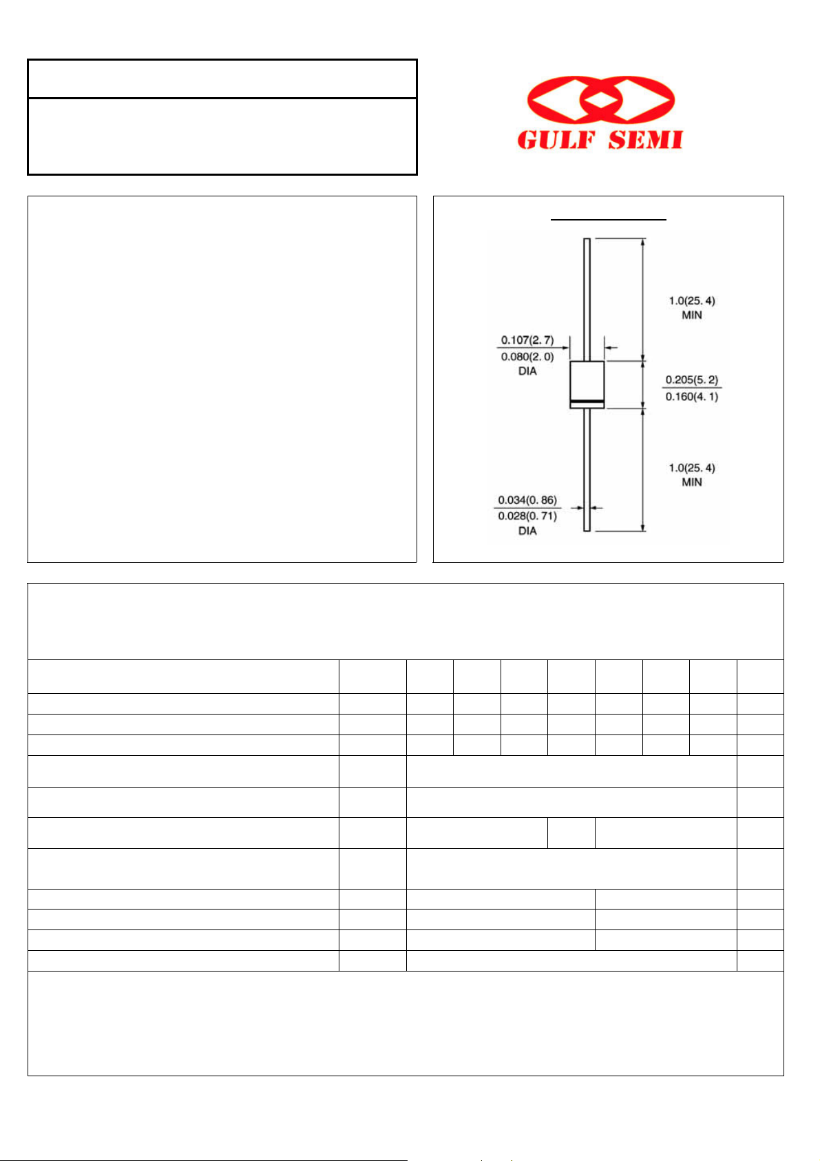
DO -41\DO-204AL
Dimensions in inches and (millimeters)
MAXIMUM RATINGS AND ELECTRICAL CHARACTERISTICS
(single-phase, half -wave, 60HZ, resistive or inductive load rating at 25°C, unless otherwise stated)
Maximum Recurrent Peak Reverse Voltage
Maximum RMS Voltage
Maximum DC blocking Voltage
Maximum Average Forward Rectified
Current 3/8”lead length at Ta =55°C
Peak Forward Surge Current 8.3ms single
half sine-wave superimposed on rated load
Maximum Forward Voltage at Forward current
1A Peak
Maximum DC Reverse Current Ta =25°C
at rated DC blocking voltage Ta =100°C
Maximum Reverse Recovery Time (Note 1)
Typical Junction Capacitance (Note 2)
Typical Thermal Resistance (Note 3)
Storage and Operating Junction Temperature
SYMBOL
Vrrm
Vrms
Vdc
If(av)
Ifsm
Vf
Ir
Trr
Cj
R(ja)
Tstg,Tj
SUF
4001
Note:
1. Reverse Recovery Condition If =0.5A, Ir =1.0A, Irr =0.25A
2. Measured at 1.0 MHz and applied reverse voltage of 4.0Vdc
3. Thermal Resistance from Junction to Ambient at 3/8”lead length, P.C. Board Mounted
SUF
4002
50 100
35 70
50 100
1.0 1.4 1.7
50 75
15 12
50 60
SUF
4003
200 400 600 800 1000
140 280 420 560 700
200 400 600 800 1000
SUF
4004
1.0
30.0
10.0
100.0
-50 to +125
SUF
4005
SUF
4006
SUF
4007
units
V
V
V
A
A
V
µA
µA
nS
pF
°C/W
°C
Rev.4, 1-Jul-03 www.gulfsemi.com
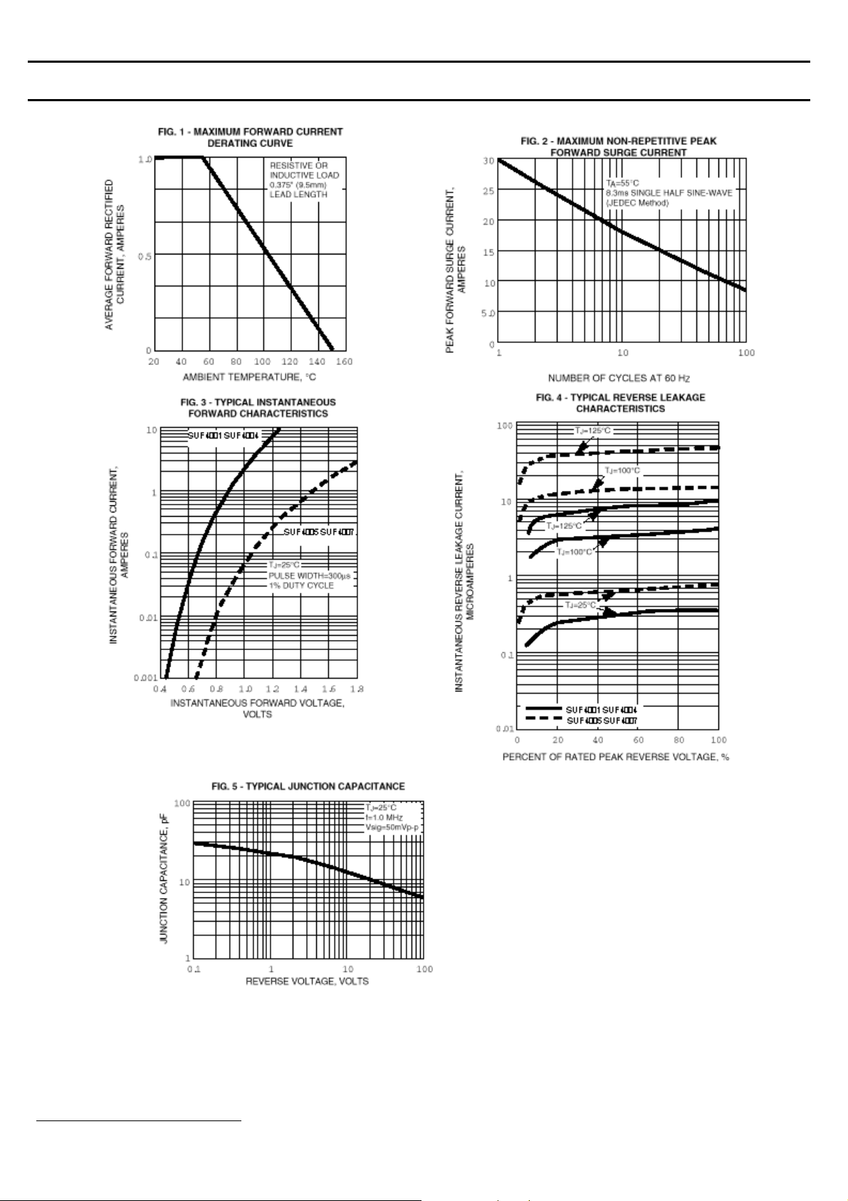
RATINGS AND CHARACTERISTIC CURVES SUF4001 THRU SUF4007
1
1
Rev.4, 1-Jul-03 www.gulfsemi.com
 Loading...