

Philips ST-D777ES Service Manual

ST-D777ES
AEP Model
UK Model
SERVICE MANUAL
DAB/FM/AM TUNER
SPECIFICATIONS
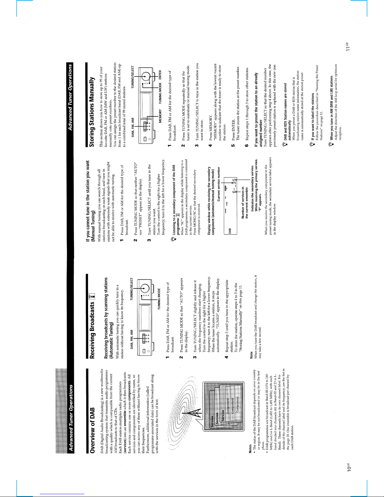
DAB tuner section
Frequency range 174.928 (5A) - 239.200 (13F) MHz
1452.960 (L1) - 1490.624 (L23) MHz
Sensitivity 6.9 µV/28 dBf
Signal-to-noise ratio 100 dB
THD+N 0.005 % (1 kHz)
Channel separation 90 dB (1 kHz)
Selectivity 35 dB (at adjacent channel)
Frequency response +0.2/-0.3 dB (5 Hz - 20 kHz)
DA converter Pulse D/A S-TACT128
Digital filter VC24 (only for DAB analog output)
Digital output Terminals: Coaxial and Optical
Sampling frequncy: 48 kHz
RDI output Optical
Aerial terminal 75 Ω, F female
FM tuner section
Frequency range 87.5 - 108.0 MHz
Sensitivity at 40 kHz derivation
at 26 dB quieting (mono) 0.9 µV/10.3 dBf
at 46 dB quieting (stereo) 23 µV/38.5 dBf
Signal-to-noise ratio at 40 kHz derivation
80 dB (mono), 76 dB (stereo)
THD+N 1 kHz, 40 kHz derivation
WIDE
0.035 % (mono), 0.045 % (stereo)
Channel separation 50 dB (1 kHz) WIDE
Selectivity at 400 kHz
WIDE 85 dB
NARROW 90 dB
Frequency respose +0.2/-0.3 dB (30 Hz - 15 kHz)
Aerial terminal 75Ω, IEC male
AM tuner section
Frequency range MW: 522 - 1,611 kHz (9 kHz step)
LW: 144 - 288 kHz
(1 kHz step: Manual tuning)
(3 kHz step: Automatic tuning)
Sensitivity (with AM loop aerial)
MW: 200 µV/m
LW: 700 µV/m
Signal-to-noise ratio MW: 54 dB (50 mV/m, 999 kHz)
LW: 50 dB (50 mV/m, 216 kHz)
Harmonic distortion 0.3 %
Sensitivity 50 dB
Aerial terminal Push lever
General
Power requirements 230 V , A C 50/60 Hz
Power consumption 20 W
Dimensions 430 × 97.5 × 374 mm (w/h/d)
Weight 6.2 kg
Remote control capability
IR
Station preset capacitymax. 99 (DAB, FM and AM total)
Supplied accessories • Audio cord (1)
• AM loop aerial (1)
• FM wire aerial (1)
• DAB wire aerial (1)
• Remote commander (1)
• R6 (size AA) baatteries (2)
Design and specifications are subject to change without notice.
2
TABLE OF CONTENTS
SAFETY-RELATED COMPONENT WARNING!!
COMPONENTS IDENTIFIED BY MARK 0 OR DOTTED LINE WITH
MARK 0 ON THE SCHEMATIC DIAGRAMS AND IN THE PARTS
LIST ARE CRITICAL TO SAFE OPERATION. REPLACE THESE
COMPONENTS WITH SONY PARTS WHOSE PART NUMBERS
APPEAR AS SHOWN IN THIS MANUAL OR IN SUPPLEMENTS
PUBLISHED BY SONY .
1. GENERAL ······································································· 3
2. TEST MODE ·································································12
3. ELECTRICAL ADJUSTMENTS····························· 14
4. DIAGRAMS ··································································· 17
4-1. BLOCK DIAGRAM·························································· 17
4-2. CIRCUIT BOARDS LOCATION ·····································18
4-3. PRINTED WIRING BOARD MAIN SECTION ············ 19
4-4. SCHEMATIC DIAGRAM MAIN SECTION (1/4) ········20
4-5. SCHEMATIC DIAGRAM MAIN SECTION (2/4) ········21
4-6. SCHEMATIC DIAGRAM MAIN SECTION (3/4) ········22
4-7. SCHEMATIC DIAGRAM MAIN SECTION (4/4) ········23
4-8. SCHEMATIC DIAGRAM DISPLAY SECTION ···········24
4-9. PRINTED WIRING BOARD DISPLAY SECTION ······25
4-10. SCHEMATIC DIAGRAM POWER SECTION ············· 26
4-11. PRINTED WIRING BOARD POWER SECTION ········ 27
4-12. IC PIN FUNCTION DESCRIPTION ·······························28
4-13. IC BLOCK DIAGRAMS ·················································· 31
5. EXPLODED VIEWS···················································· 34
5-1. FRONT PANEL SECTION··············································· 34
5-2. MAIN SECTION······························································· 35
6. ELECTRICAL PARTS LIST ···································· 36
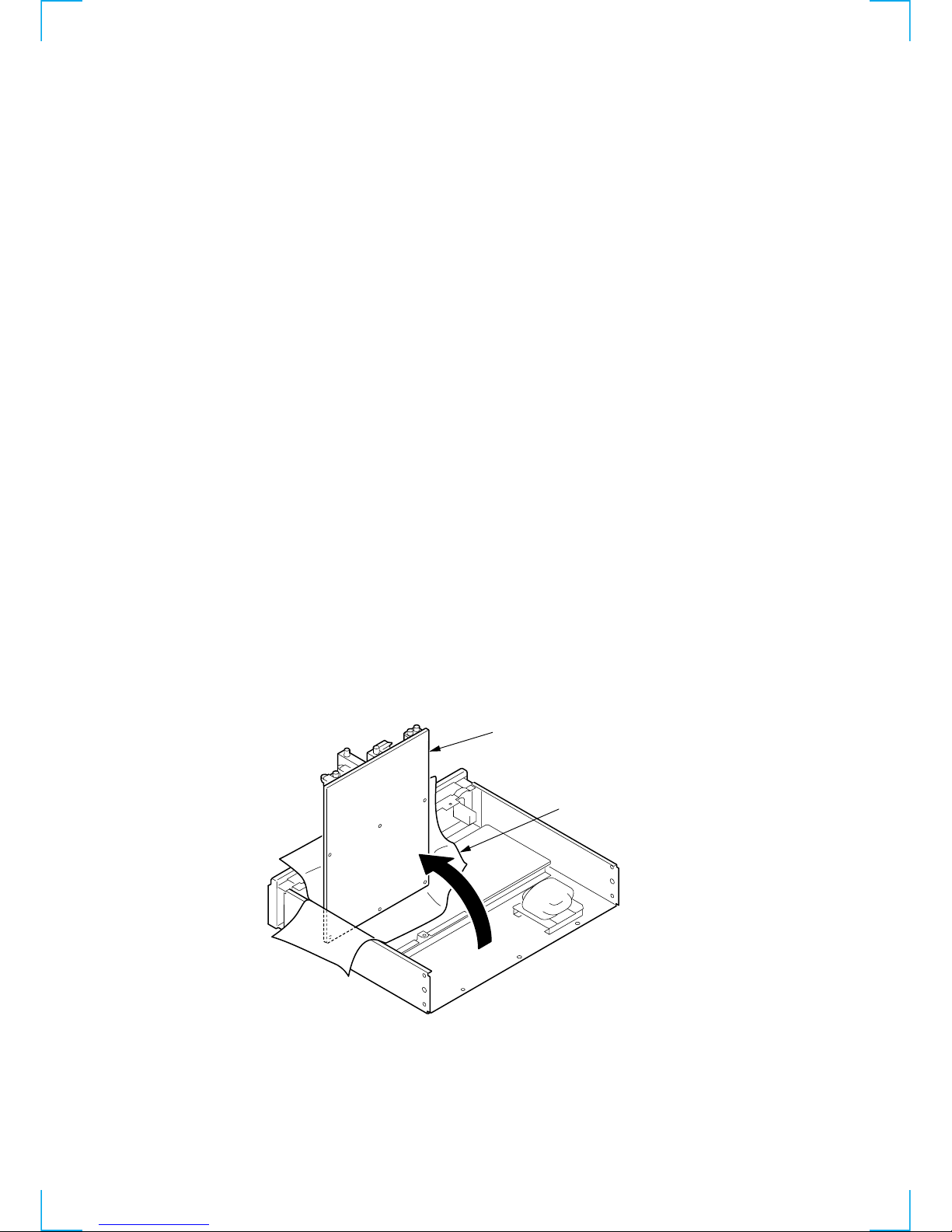
SERVICE POSITION
• The service position of the MAIN board is the state in which the back-panel is removed
and the MAIN board is swing-raised by 90 °.
(An insulating material is necessary to prevent the machine from shorting.)
Insulating material
MAIN board
3
SECTION 1
GENERAL
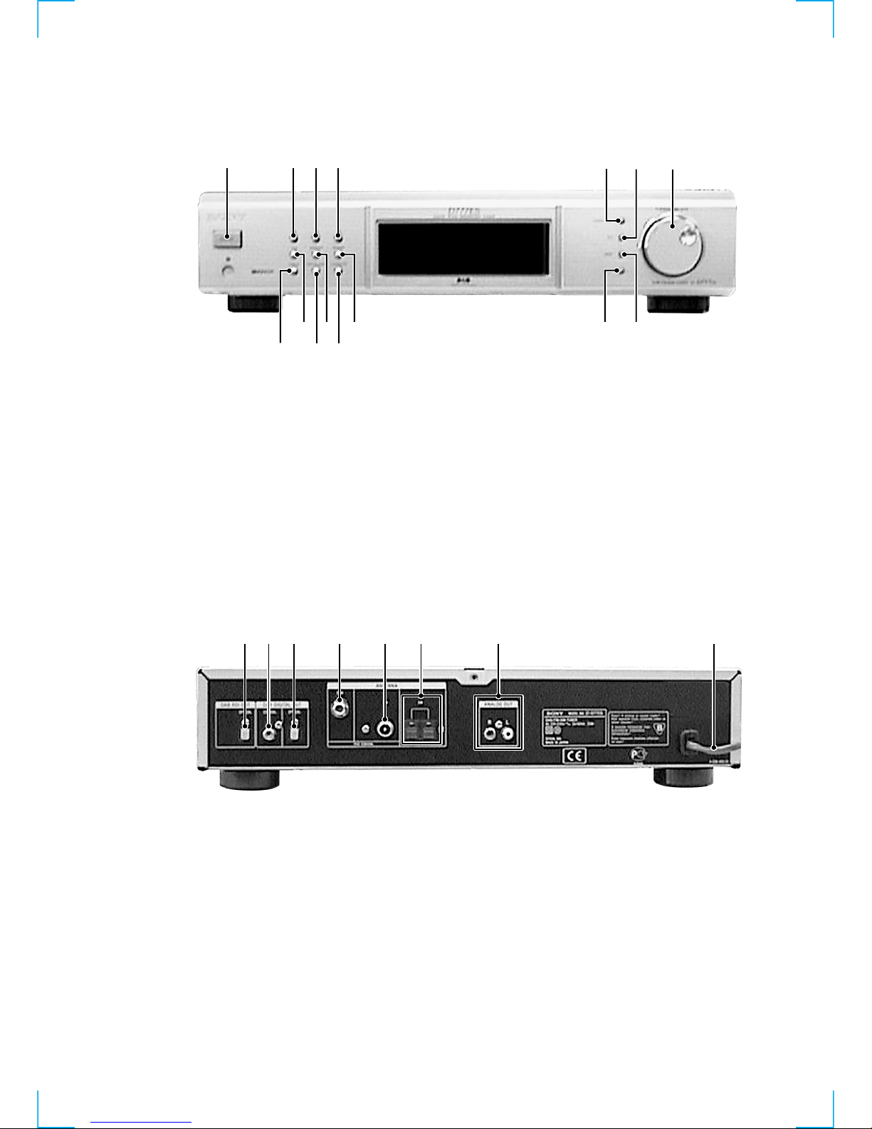
FRONT PANEL
REAR PANEL
1 234
8
765
9
qd qa
0qsqf
qg
1 2 3 4 5 6 7 8
1 ?/1 switch
2 DAB button
3 FM button
4 AM button
5 TUNING MODE button
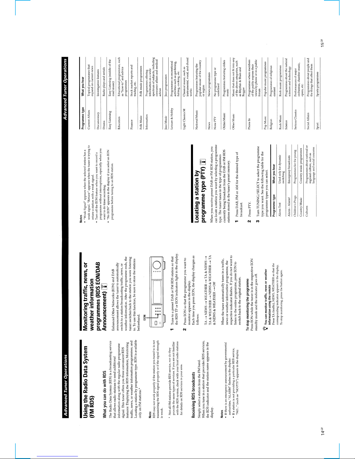
6 PTY button
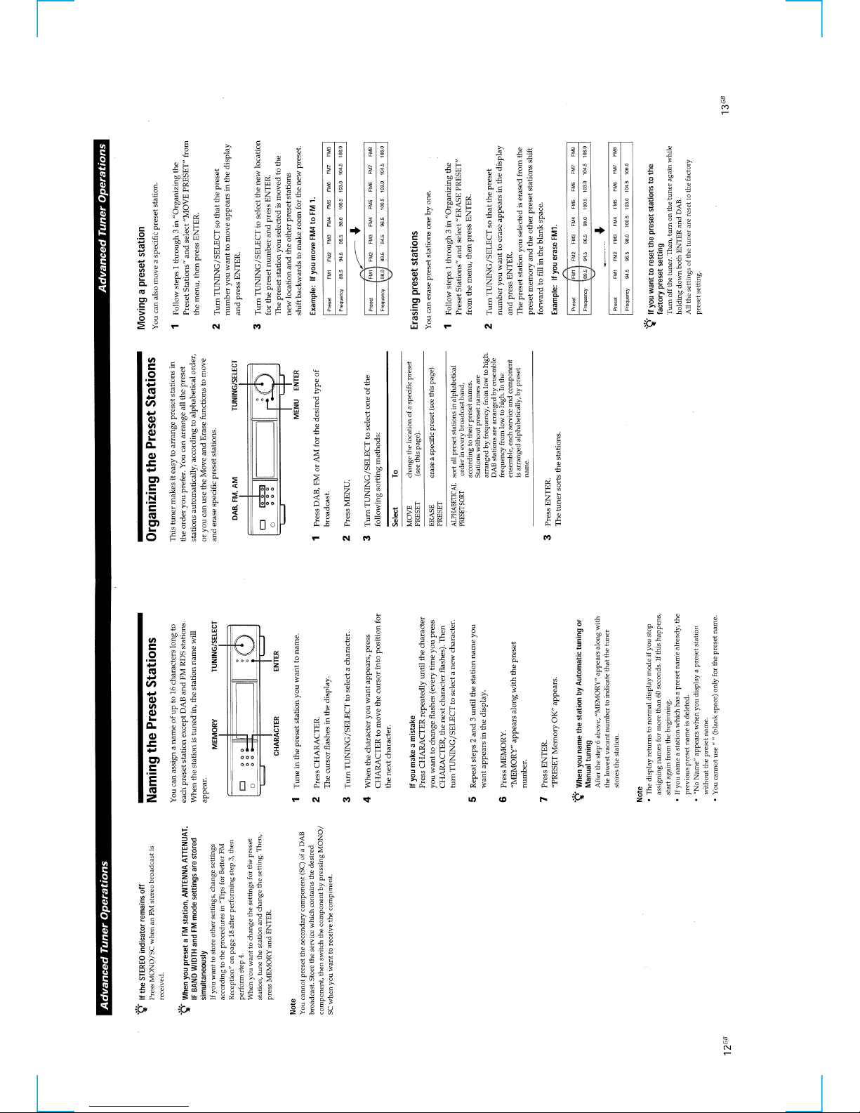
7 TUNING/SELECT button
8 MENU button
9 ENTER button
0 MEMORY button
qa CHARACTER button
qs MONO/SC button
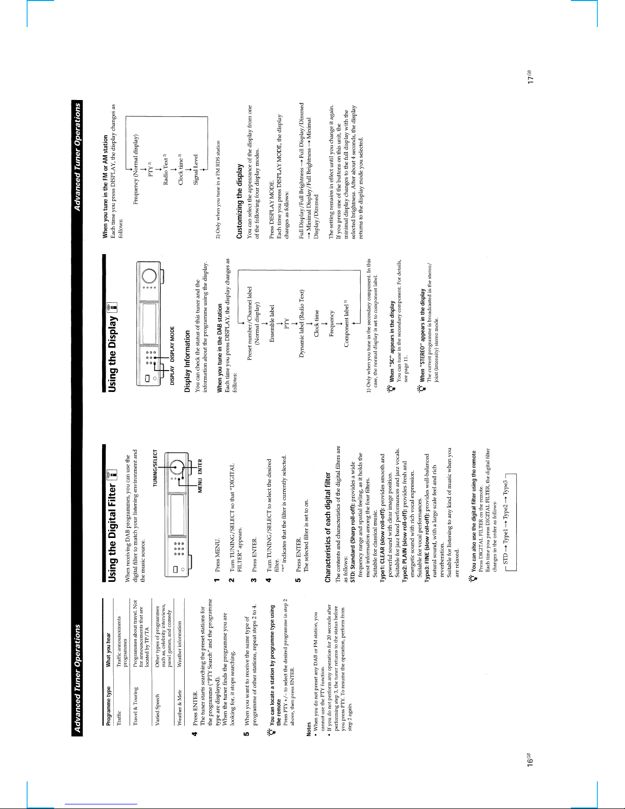
qd DISPLAY MODE button
qf EON button
qg DISPLAY button
1 DAB RDI OUT OPTICAL jack
2 DAB DIGITAL OUT COAXIAL jack
3 DAB DIGITAL OUT OPTICAL jack
4 ANTENNA DAB jack
5 ANTENNA FM jack
6 ANTENNA AM terminal
7 ANALOG OUT jack
8 POWER cord

4
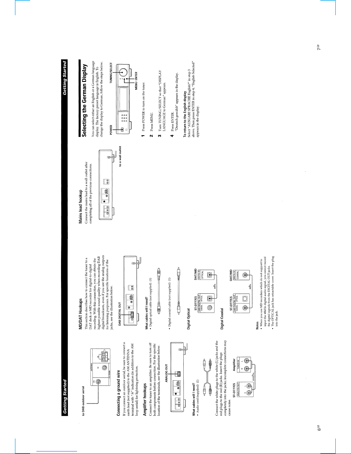
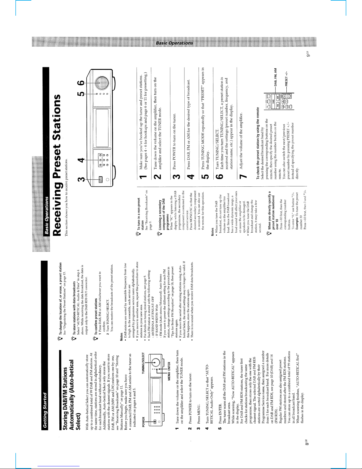
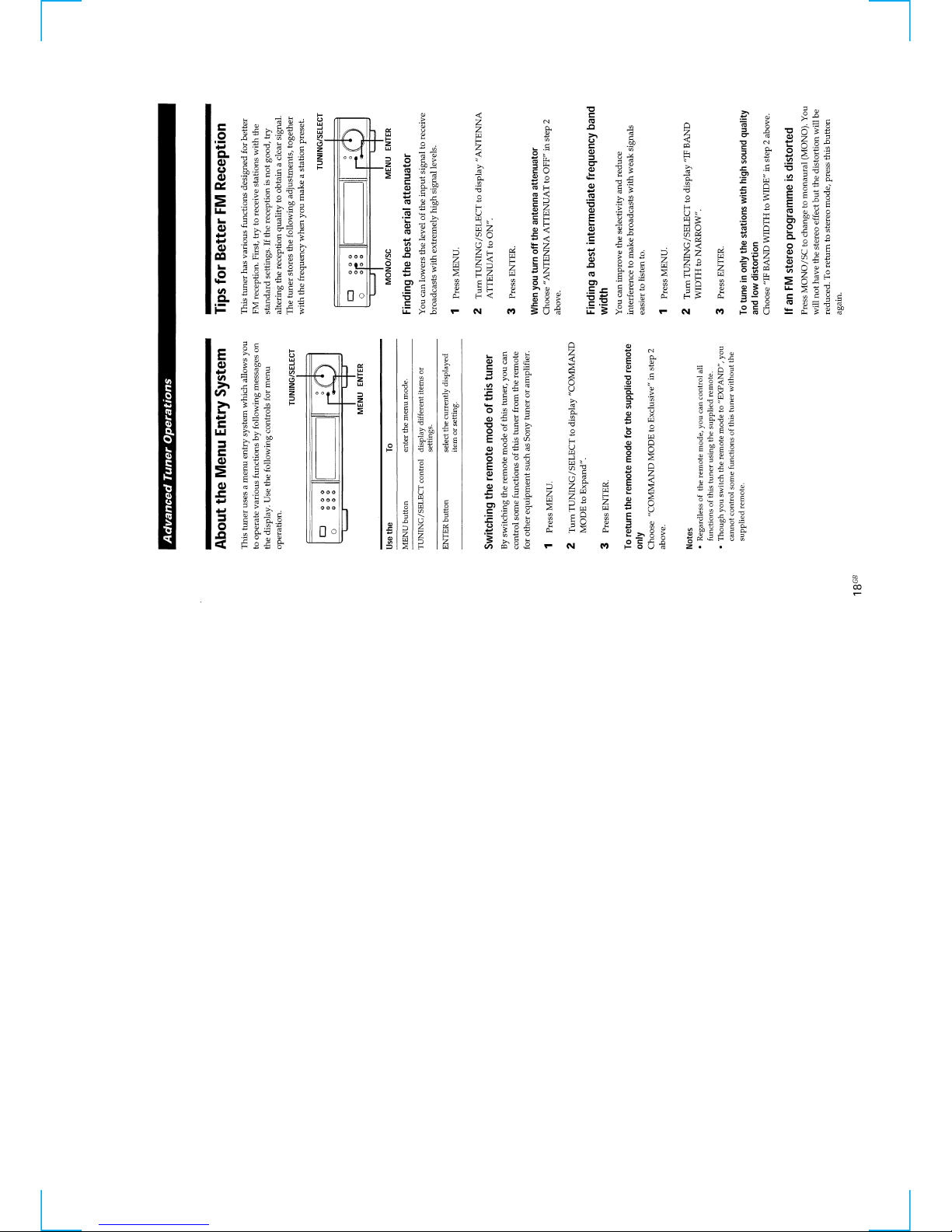
This section is extracted
from instruction manual.
5
6
7
8
9
10
11
12
2. Entering the Factory Preset (In case perform just to write memory of the Factory Preset.)
1. Turn OFF the power.
2. While pressing [ENTER] and [DAB] together, turn ON [POWER] .
3. Microprocessor Version Display Mode
1. Turn off the power.
2. While pressing [MENU] and [AM] together, turn ON [POWER] .
3. The version and the date of the microprocessor are displayed.
4. Press the [ENTER] button to end this mode.
SECTION 2
TEST MODE
DAB
FM
AM
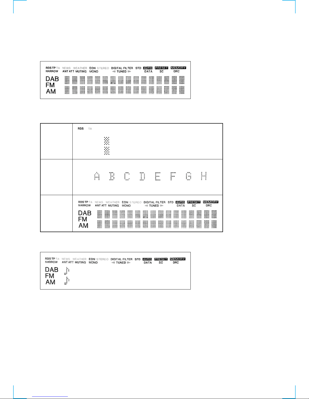
1. Display Tube Check and KEY Check mode
1. Turn OFF the power.
2. While pressing [DISPLAY] and [MENU] together, turn ON [POWER] .
3. Display tube all lit.
4. Each time the button is pressed, the key number is counted down. After all the 14 buttons are pressed, “OK” appears.
When the [DAB], [FM] or [AM] button is pressed only, the following display appears.
5. The two eighth notes are moved from the left to the right by turning the [TUNING/SELECT] dial clockwise. The notes are mov ed from
the right to the left by turning the dial counterclockwise.
13
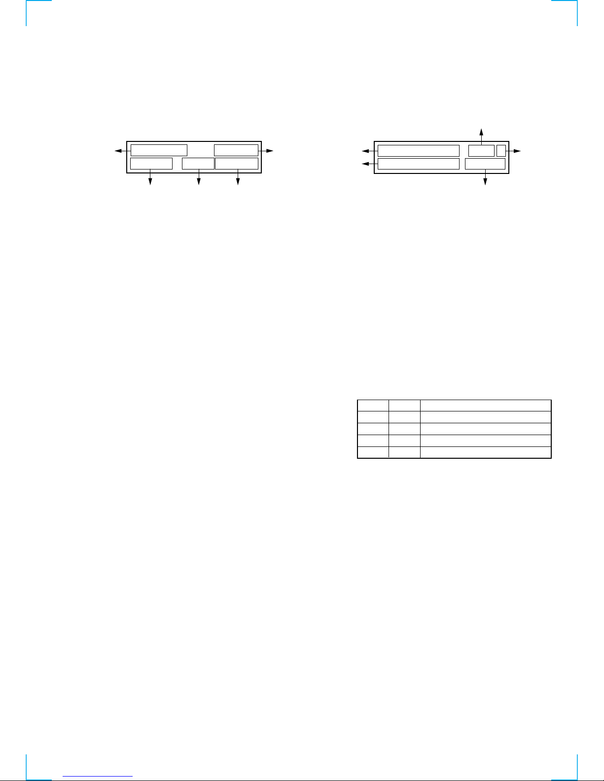
• DAB error rate display
Press [DAB] and [CHARACTER] at the same time under the DAB
tuned condition. (When the software version is 1.04, press [DAB]
ten times while [CHARACTER] is kept pressed.)
The bit error rate is displayed.
1: PIC error rate
2: MSC error rate
3: Bit rate
4: In case of audio service
F : 48 kHz sampling
H : 24 kHz sampling
In case of data service
S : stream data
F : FIDC
P : pocket data
5: DAB decoder status information
Check the contents in binary notation.
Bit 7 : not used
Bit 6 : 1 when AFC is converged.
Bits 5 to 3 : The number of CRC errors during MPEG
decode
Bit 2 : 1 when initial pulling-in is complete.
Bits 1, 0 : Contents of DAB frame length judgment
• Audio information display (DAB only)
Press [DISPLAY] and [ENTER] at the same time under the D AB tuned
condition.
Audio information for service that is selected at present is displayed.
1: Bit rate
2: Audio contents
stereo = stereo broadcast
joint = joint stereo broadcast
dual = dual channel broadcast
single = single channel broadcast
stream = stream data broadcast
FIDC = FIDC data broadcast
Packet = packet data broadcast
3: Sampling frequency
4: Protection level
5: Transmission mode
2 5 6 k b p s
4 8 k H z
s t e r e o
P L v 2 m o d e 1
1
34
5
2
F : 0 . 0 0 E + 0 0
M : 0 . 0 0 E + 0 0
2 5 6 F
S T : C 5
1
5
4
2
3
Bit 1
0
0
1
1
Frame length
96 ms
48 ms
24 ms
Judgment impossible
Bit 0
1
0
0
1
14
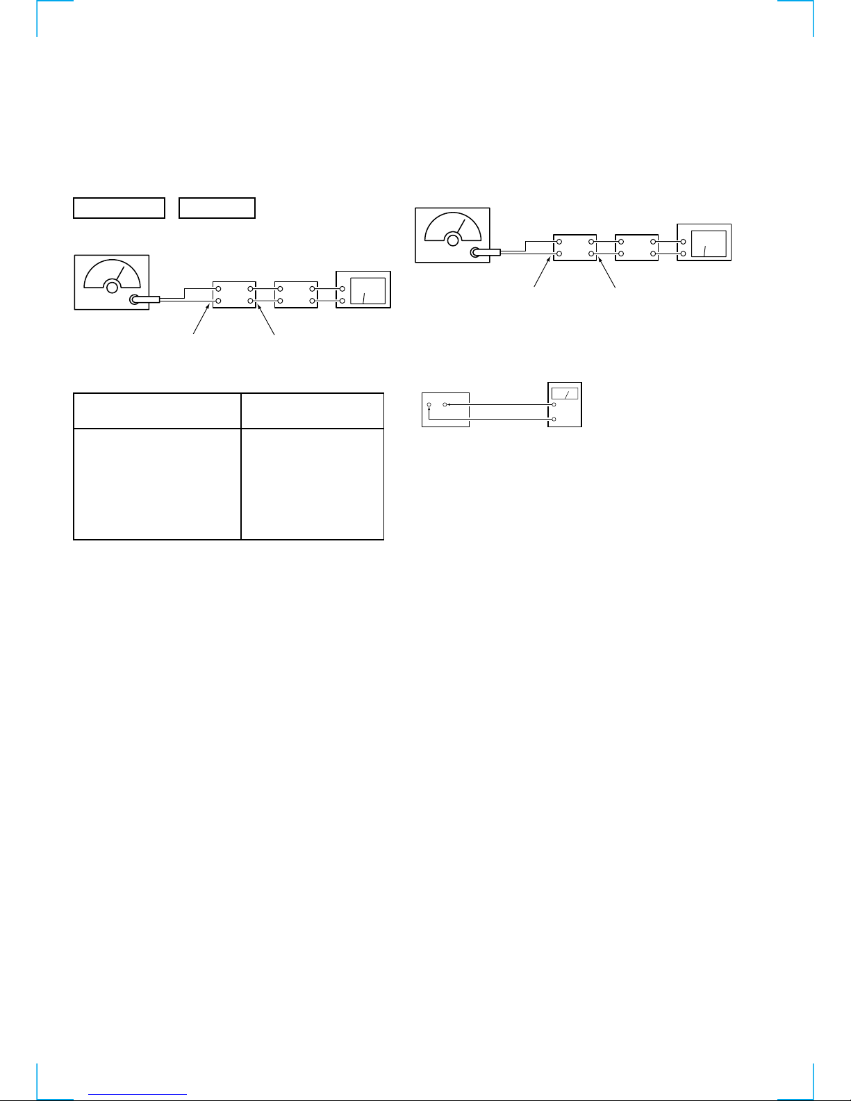
FM Discriminator ADJUSTMENT
(NULL and MONO Distortion Adjustment)
Setting:
Procedure:
1. Tune the set to 98 MHz.
2. Adjust IFT202 for 0V reading on the digital voltmeter.
................... NULL
3. Adjust IFT203 for a minimum reading on the distortion meter.
................... MONO Distortion (THD)
4. Repeat the adjustments of 2 and 3 several times.
Note : When replacing the ceramic filter, perform this alignment.
SECTION 3
ELECTRICAL ADJUSTMENTS
Precautions in Repairing
If the front end unit fails, it is difficult to repair the inner circuits, so
replace the entire front end unit.
• Standard Setting of FM Stereo RF Signal Generator.
FM SECTION 0dB = 1µV
set
FM RF SSG
1kHz
highpass
filter
distortion mete
r
FM ANTENNA (75Ω)
LINE OUT
STEREO STANDARD SIGNAL
MONAURAL
STANDARD SIGNAL
Carrier frequency : 98MHz
Modulation : Audio 1kHz
Main channel (L+R) : 33.75kHz
deviation
Sub channel (L–R) : 33.75kHz
deviation
Pilot : 7.5kHz
Deviation
Carrier frequency : 98MHz
Modulation : Audio 1kHz
75kHz deviation
set
FM RF SSG
1kHz
highpass
filter
distortion mete
r
FM ANTENNA (75Ω)
Modulation : Monaural Standard signal
Output level : 6mV (76dB) (at 75 Ω open)
LINE OUT
Digital Voltmete
r
(DC range)
TP201
NULL terminal
All the settings are performed in the Factory Preset state. (Refer to page 13.)
 Loading...