


Instructions for Use
Avalon Fetal Monitor
FM20/30, FM40/50, Avalon CL
Release L.3 with Software Revision L.3x.xx
Patient Monitoring


1Table of Contents
1 Introduction 9
Who this Book is For 9
Confirm Fetal Life Before Using the Monitor 10
Introducing the Avalon Family of Fetal Monitors 11
2 What's New 21
What's New in Release L.3 21
What's New in Release J.3 23
3 Basic Operation 27
Supported Measurements 28
Avalon FM20 and FM30 29
Avalon FM40 and FM50 30
Getting to Know Your Avalon FM20/FM30 31
Getting to Know Your Avalon FM40/FM50 34
Connecting the Monitor to AC Mains 36
Wired Transducers 36
Operating and Navigating 38
Operating Modes 44
Automatic Screen Layouts 45
Settings 45
Preparing to Monitor 48
After Monitoring 70
Switching the Monitor to the Standby Screen 71
Disconnecting from Power 71
Power On/Power Off Behavior 71
Monitoring After a Power Failure 72
Troubleshooting 72
4 Cableless Monitoring 73
Avalon CL Transducer System 73
Basics of Cableless Systems 74
Twins and Triplets Support 75
Configuration of Cableless Systems 75
Getting to Know Your Avalon CL 76
Cableless Transducers 84
CL Pods 89
Calling Patients 93
Telemetry 94
Preparing to Monitor Cablelessly 100
3

Battery Lifetime Management 106
Patient Transport Within the Hospital 107
Underwater Monitoring 108
5 FM20/30 Battery Option 109
External Power Supply M8023A 109
Using Batteries 110
Optimizing Battery Performance 113
Storing the Battery 115
Cableless Monitoring with FM20/30 Battery Option 116
Patient Transport Within the Hospital 116
6 Alarms 117
Alarm Mode 118
Nurse Call Systems 118
Visual Alarm Indicators 119
Audible Alarm Indicators 119
Acknowledging Alarms 121
Acknowledging Disconnect INOPs 121
Alarm Reminder 122
Pausing or Switching Off Alarms 122
Alarm Limits 124
Reviewing Alarms 126
Latching Alarms 126
Testing Alarms 128
Alarm Behavior at Power On 128
7 Patient Alarms and INOPs 129
Alarm Messages 129
Technical Alarm Messages (INOPs) 132
8 Admitting and Discharging 147
Admit/Discharge on the Monitor 147
New Patient Check 149
OB TraceVue/IntelliSpace Perinatal 149
9 Non-S tress Test Timer 151
Setting NST Autostart/Autostop 151
Viewing the NST Timer 151
Timer Expiry Notification 151
Accessing the NST Setup Pop-up Keys 152
10 Non-S tress Test Report 153
Setting Up an NST Report 153
NST Report Status Window 154
NST Criteria 157
4

11 Cross-Channel Verification (CCV) 159
Misidentification of Heart Rates 159
Cross-Channel Verification Functionality 160
Overview of Cross-Channel Comparisons 161
Coincidence Examples 162
Recommended Actions for Coincidence INOP 164
12 Monitoring FHR and FMP Using Ultrasound 165
Technical Description 165
Limitations of the Technology 166
Misidentification of Maternal HR as FHR 166
What You Need 166
Cableless Monitoring - Important Considerations 167
Preparing to Monitor 168
Selecting Fetal Heart Sound 169
Changing the Fetal Heart Sound Volume 170
Fetal Movement Profile 170
Troubleshooting 172
Additional Information 173
13 Monitoring Twin FHRs 183
Important Considerations 183
Monitoring Twins Externally 184
Monitoring Twins Internally 185
Separating FHR Traces 185
Troubleshooting 189
14 Monitoring Triple FHRs 191
Important Considerations 191
Monitoring Triplets 192
Separating FHR Traces 192
"Standard" Separation Order 193
"Classic" Separation Order 194
Switching Trace Separation On and Off 195
When Trace Separation is On 195
When Trace Separation is Off 195
Troubleshooting 196
15 Fetal Heart Rate Alarms 197
Changing Alarm Settings 197
Changing Signal Loss Delay 198
16 Monitoring FHR Using DECG 199
Misidentification of Maternal HR as FHR 199
What You Need 200
Making Connections 202
5

Monitoring DECG 202
Suppressing Artifacts 204
Troubleshooting 205
Testing DECG Mode 205
17 Monitoring Uterine Activity Externally 207
What You Need 207
External Toco Monitoring 208
Toco Sensitivity 208
Troubleshooting 208
18 Monitoring Uterine Activity Internally 211
What You Need 211
Internal (IUP) Monitoring 213
Troubleshooting 214
19 Monitoring aFHR, aHR, and aToco 215
Fetal Heart Rate aFHR 215
Uterine Activity aToco 216
What You Need 217
At the Monitor 217
Troubleshooting 218
20 Monitoring Maternal Heart / Pulse Rate 221
Priority for Maternal Heart / Pulse Rate 221
Misidentification of Maternal HR for FHR 222
Maternal HR from MECG Electrodes 222
Monitoring MECG Wave 225
Pulse Rate from Toco MP 227
Pulse Rate from SpO2 228
Adjusting the Heart Rate / Pulse Alarm Limits 228
Average Pulse Rate from Noninvasive Blood Pressure 228
Testing MECG Mode 229
21 Printing the ECG Waveform 231
22 Monitoring Noninvasive Blood Pressure 235
Introducing the Oscillometric Noninvasive Blood Pressure Measurement 235
Preparing to Measure Noninvasive Blood Pressure 237
Starting and Stopping Measurements 239
Enabling Automatic Mode and Setting Repetition Time 239
Enabling Sequence Mode and Setting Up the Sequence 240
Choosing the Alarm Source 240
Assisting Venous Puncture 241
Calibrating NBP 241
Troubleshooting 242
6

23 Monitoring SpO2 243
Selecting an SpO2 Sensor 243
Applying the Sensor 243
Connecting SpO2 Cables 244
Measuring SpO2 244
SpO2 Signal Quality Indicator (FAST SpO2 only) 245
Assessing a Suspicious SpO2 Reading 246
Understanding SpO2 Alarms 246
Setting Up Tone Modulation 247
Setting the QRS Volume 247
24 Monitoring Maternal Temperature 249
Measuring Tympanic Temperature 249
Entering Temperature Manually 254
25 Paper Save Mode for Maternal Measurements 255
26 Recovering Data 257
Recovering Traces on Paper 257
Recovering Traces on an OB TraceVue/IntelliSpace Perinatal System 258
Manually Recording Stored Data 258
27 Care and Cleaning 261
General Points 261
Cleaning and Disinfecting 262
Cleaning and Disinfecting Monitoring Accessories 263
Cleaning and Disinfecting the Tympanic Temperature Accessories 264
Cleaning and Disinfecting CL Transducers and CL Pods 264
Sterilizing 265
28 Maintenance 267
Inspecting the Equipment and Accessories 267
Inspecting the Cables and Cords 268
Maintenance Task and Test Schedule 268
Recorder Maintenance 269
Cleaning the Print Head 273
Returning Equipment for Repair 273
Disposing of the Monitor 274
29 Accessories and Supplies 275
Information on Latex 275
Avalon CL Base Station 275
Transducers 276
Fetal Accessories 276
Noninvasive Blood Pressure Accessories 278
SpO2 Accessories 280
7

Tympanic Temperature Accessories 285
Recorder Paper 285
Batteries 285
30 Specifications and Standards Compliance 287
Environmental Specifications 287
Physical Specifications 289
Interface Specifications 293
Performance Specifications 295
Recorder Specifications 308
External Displays: FM40/FM50 Only 310
Manufacturer's Information 310
Trademark Acknowledgment 310
Regulatory and Standards Compliance 311
Environment 321
Monitoring After a Loss of Power 321
ESU, MRI, and Defibrillation 321
Cardiac Pacemakers and Electrical Stimulators 322
Fast Transients/Bursts 322
Symbols on the System 322
31 Default Settings Appendix 327
Alarm and Measurement Default Settings 327
Recorder Default Settings 330
Index 333
8

1Introduction
Who this Book is For
This book is for trained healthcare professionals using the Avalon FM20, FM30, FM40, and FM50
fetal/maternal monitors, and the Avalon CL Transducer System. It describes how to set up and use the
monitor and transducers. Familiarize yourself with all instructions including warnings and cautions
before starting to monitor patients. Read and keep the Instructions for Use that come with any
accessories, as these contain important information about application, care, and cleaning that is not
repeated in this book.
If you have received this Instruction for Use because your fetal monitor has been upgraded to a newer
software version L.3, be aware that the standards compliance information contained in the
Instructions for Use for L.3 does not apply to your fetal monitor. Refer to your original Instructions
for Use for standards compliance information.
You should be:
1
• Trained in the use of fetal heart rate (FHR) monitors.
• Trained in the interpretation of FHR traces.
• Familiar with using medical devices and with standard fetal monitoring procedures.
For information on how to configure and service the monitor, see the Configuration Guide and the
Service Guides, or contact your authorized service provider.
Your monitor may not have all of the features and options described in this guide. The exact
appearance of the monitor may differ slightly from that shown in the illustrations.
This guide may contain descriptions of functionality and features that are not implemented in the
equipment currently shipped to Japan and/or of products that are not currently sold in Japan due to
limitations and restrictions under the applicable local laws and regulations in Japan. Please contact your
local sales representative and/or Philips Customer Support for details.
In this guide:
•A warning alerts you to a potential serious outcome, adverse event, or safety hazard. Failure to
observe a warning may result in death or serious injury to the user or patient.
•A caution alerts you to where special care is necessary for the safe and effective use of the
product. Failure to observe a caution may result in:
– minor or moderate personal injury,
– damage to the product or other property,
– possibly in a remote risk of more serious injury.
9

1 Introduction
• Monitor refers to the entire fetal/maternal monitor. Display refers to the physical display unit.
Screen refers to everything you see on the monitor's display, such as measurements, alarms,
patient data, and so forth.
FM30 • Whenever a monitor’s identifier appears to the left of a heading or paragraph, it means that the
information applies to that monitor only. Where the information applies to all models, no
distinction is made.
Avalon CL
Avalon CTS
Whenever one of these identifiers appear to the left of a heading or paragraph, it means that the
information applies to that cableless transducer system. Where the information applies to both
systems, no distinction is made.
For installation instructions and technical description, see the corresponding Service Guide of the fetal
monitors.
Confirm Fetal Life Before Using the Monitor
Fetal monitoring technology available today is not always able to differentiate a fetal heart rate (FHR)
signal source from a maternal heart rate (MHR) source in all situations. Therefore, you should confirm
fetal life by independent means before starting to use the fetal monitor, for example, by palpation of fetal
movement or auscultation of fetal heart sounds using a fetoscope, stethoscope, or Pinard stethoscope.
If you cannot hear the fetal heart sounds, and you cannot confirm fetal movement by palpation,
confirm fetal life using obstetric ultrasonography. Continue to confirm that the fetus is the signal
source for the FHR during monitoring.
Be aware that:
• a maternal HR trace can exhibit features that are very similar to those of an FHR trace, even
including accelerations and decelerations. Do not rely solely on trace pattern features to identify a
fetal source.
• Fetal Movement Profile (FMP) annotations on a fetal trace alone may not always indicate that the
fetus is alive. The body of a deceased fetus can move and cause the monitor to annotate fetal body
movements.
10
Here are some examples where the maternal HR can be misidentified as the FHR.
When using an ultrasound transducer:
• It is possible to pick up maternal signal sources, such as the aorta or other large vessels.
• Misidentification may occur when the maternal HR is higher than normal (especially when it is
over 100 bpm).
When using a fetal scalp electrode:
• Electrical impulses from the maternal heart can sometimes be transmitted to the fetal monitor
through a recently deceased fetus via the spiral scalp electrode cable, appearing to be a fetal signal
source.
• The recorded maternal HR (and any artifact) can be misinterpreted as an FHR (especially when it
is over 100 bpm).
When Fetal Movement Profile (FMP) is enabled:
FMP annotations in the absence of fetal life may be a result of:
• Movement of the deceased fetus during or following maternal movement.
• Movement of the deceased fetus during or following manual palpation of fetal movement
(especially if the pressure applied is too forceful).

1 Introduction
• Movement of the ultrasound transducer.
• The ultrasound transducer detecting a maternal movement source, such as the mother coughing.
See also “Monitoring FHR and FMP Using Ultrasound” on page 165 and “Monitoring FHR Using
DECG” on page 199.
To reduce the possibility of mistaking the maternal HR for an FHR, it is recommended that you
monitor both maternal and fetal heart rates. The monitor's cross-channel verification (CCV) feature
can help by automatically detecting when a maternal HR coincides with an FHR. For further details,
see “Cross-Channel Verification (CCV)” on page 159.
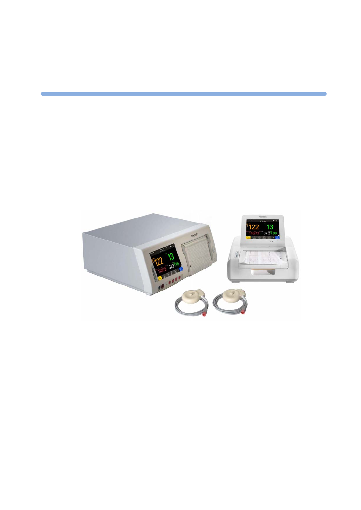
Introducing the Avalon Family of Fetal Monitors
The Avalon family of fetal monitors consists of the Avalon FM20, FM30, FM40, and FM50. While the
FM20/FM30 and the FM40/FM50 have different form factors, the method of operation is very
similar for all monitors. The Avalon fetal monitors also share transducers, accessories, software, and
are compatible with the Avalon CL, and Avalon CTS Fetal Transducer Systems.
Intended Use
The Philips Avalon FM20 (M2702A), FM30 (M2703A), FM40 (M2704A), and FM50 (M2705A) fetal/
maternal monitors are intended for:
• noninvasive monitoring of fetal heart rates and movements.
• noninvasive monitoring of maternal heart rates, maternal pulse rates, uterine activity, maternal
noninvasive blood pressure, maternal oxygen saturation, and maternal temperature.
• invasive monitoring of direct fetal heart rate, intrauterine pressure, and for displaying and
recording of fetal and maternal electrocardiogram (ECG) (FM30 and FM50 only).
• displaying, storing, and recording patient data and parameter values, and for generating alarms
from fetal and maternal parameters.
• transmitting patient data and parameter values to a patient information and surveillance system.
• use by trained health care professionals.
• use in antepartum testing areas, in labor and delivery rooms, and during postpartum recovery in
the hospital environment. They are not intended for use in intensive care units or operating rooms.
+
• monitoring in a bath or shower (Avalon CL cableless transducers Toco
ECG/IUP only).
• transport situations in healthcare facilities, for healthcare facilities outside hospitals, such as
doctors’ offices, and for use in private households (FM20 and FM30 only).
MP, Ultrasound, and
11

1 Introduction
WARNING
The fetal/maternal monitors are not intended for:
• use during defibrillation, electro-surgery, or magnetic resonance imaging (MRI).
• Electrocardiography (ECG) measurements on patients connected to electrical stimulator or with
cardiac pacemakers.
• use of the invasive measurements IUP and fetal DECG, use of the patient module (M2738A) and
use of the Avalon CL system in domestic establishments, and those connected directly to the
public low-voltage supply network that supplies buildings used for domestic purposes.
• measuring the maternal temperature using the tympanic thermometer (866149) in private
households.
WARNING
No modification of the fetal monitors, transducers, and the Avalon CL base station is allowed.
CAUTION
U.S. federal law restricts this device to sale by, or on the order of, a physician.
All users must read the Instructions for Use before working with the fetal monitor. Disregarding the
contents of the Instructions for Use is considered abnormal use.
12

Indications for Use
Avalon Fetal/Maternal Monitor FM20
Indicated for use by trained health care professionals whenever there is a need for monitoring the
physiological parameters uterine activity, heart rate, oxygen saturation, noninvasive blood pressure,
pulse rate, and temperature of pregnant women, and the fetal heart rates of single fetuses, twins, and
triplets in labor and delivery rooms, in antepartum testing areas, in private households and during
transports in healthcare facilities.
Avalon Fetal/Maternal Monitor FM30
Indicated for use by trained health care professionals whenever there is a need for monitoring the
physiological parameters uterine activity, heart rate, electrocardiography (ECG), oxygen saturation,
noninvasive blood pressure, and pulse rate, and temperature of pregnant women, and the fetal heart
rates of single fetuses, twins, and triplets in labor and delivery rooms, in antepartum testing areas, in
private households and during transports in healthcare facilities.
Avalon Fetal/Maternal Monitor FM40
Indicated for use by trained health care professionals whenever there is a need for monitoring the
physiological parameters uterine activity, heart rate, oxygen saturation, noninvasive blood pressure,
and pulse rate, and temperature of pregnant women, and the fetal heart rates of single fetuses, twins,
and triplets in labor and delivery rooms and in antepartum testing areas.
Avalon Fetal/Maternal Monitor FM50
Indicated for use by trained health care professionals whenever there is a need for monitoring the
physiological parameters uterine activity, heart rate, electrocardiography (ECG), oxygen saturation,
noninvasive blood pressure, and pulse rate, and temperature of pregnant women, and the fetal heart
rates of single fetuses, twins, and triplets in labor and delivery rooms and in antepartum testing areas.
1 Introduction
Safety Information
In this guide:
• A warning alerts you to a potential serious outcome, adverse event or safety hazard. Failure to
observe a warning may result in death or serious injury to the user or patient.
• A caution alerts you to where special care is necessary for the safe and effective use of the product.
Failure to observe a caution may result in minor or moderate personal injury or damage to the
product or other property, and possibly in a remote risk of more serious injury.
13

1 Introduction
No Host Monitoring
No Host Monitoring
cl NBP Disconnect
cl
SpO Disconnect
Electrical Hazards
WARNING
Electrical shock hazard: Do not open the monitor housing. Refer all servicing to qualified service
personnel.
• Always use the supplied power cord with the earthed mains plug to connect to an earthed AC
mains socket. Never adapt the mains plug from the fetal monitor to fit an unearthed AC mains
socket.
• Do not use AC mains extension cords or multiple portable socket-outlets.
• FM20/FM30 only: The protective earth conductor is required for EMC purposes. It has no
protective function against electric shock. Double and/or reinforced insulation protects this
device against electric shock.
• Do not connect any devices that are not supported as part of a system.
• Any non-medical device placed and operated in the patient’s vicinity must be powered with an
approved isolation transformer that ensures mechanical fixing of the power cords, and covering of
any unused power outlets.
• The fetal/maternal monitor is NOT intended for use during defibrillation, electro-surgery, or
MRI. Remove all transducers, sensors, and accessories before performing electro-surgery,
defibrillation, or MRI, otherwise harm to the patient or the user can result.
• Do not touch the charging contacts for the cableless transducers at the Avalon CL base station
while you are touching the patient.
Leakage currents: If several items of equipment used to monitor a patient are interconnected, the
resulting leakage current may exceed allowable limits.
Radio Frequency Interference
WARNING
• Short range radio connections are subject to interruption due to interference from other radio
sources in the vicinity, including microwaves, bluetooth devices, WLAN devices (802.11b,g,n), and
cordless phones. Depending on the strength and duration of the interference, the interruption may
occur for an extended period. A loss of connection, due to moving out-of-range, interference, or
for other reasons, is indicated with a
on the IntelliVue CL NBP or CL SpO
INOP at the fetal monitor. Correct channel configuration is important, refer to
the Service Guides and the Configuration Guide for details.
• To avoid magnetic interference affecting the mode of the pacemaker, ensure that the
Avalon CL base station does not come into close contact with implanted pacemakers.
• This equipment generates, uses, and radiates radio-frequency energy, and if it is not installed and
used in accordance with its accompanying documentation, may cause interference to radio
communications. Operation of this equipment in a residential area may cause interference, in
which case the users must take whatever measures may be required to correct the interference.
• Do not use cordless/mobile phones or any other portable RF communication system within the
patient vicinity, or within a 1.0 m radius of any part of the fetal monitoring system.
Pods, or a
2
INOP (here the host is the fetal monitor)
, or
, or
14

• For paced patients: The radiated SRR power of the CL SpO2, CL NBP Pods, CL F&M Pod, and
the CL Wide Range Pod, and other sources of radio-frequency energy, when used in very close
proximity of a pacemaker, might be sufficient to interfere with pacemaker performance. Due to
shielding effects of the body, internal pacemakers are somewhat less vulnerable than external
pacemakers. However, caution should be exercised when monitoring paced patients.
• In order to minimize the possibility of interference, avoid positioning and wearing the Cableless
Measurement Devices in very close proximity to a pacemaker. Consult the pacemaker
manufacturer for information on the RF susceptibility of their products.
Use Environment
WARNING
Explosion Hazard:
• Do not use in the presence of flammable anesthetics, such as a flammable anesthetic mixture with
air, oxygen, nitrous oxide, or in oxygen rich environment. Use of the devices in such an
environment may present an explosion hazard.
• Use only Philips batteries part number M4605A with the FM20 or FM30 with battery option. Use
of a different battery may present a risk of fire or explosion.
1 Introduction
Environmental Specifications:
• The performance specifications for the monitors, measurements, and accessories apply only for
use within the temperature, humidity, and altitude ranges specified in “Environmental
Specifications” on page 287.
Liquid Ingress:
• Do not operate the monitor if it is wet. If you spill liquid on the monitor, contact your service
personnel, or Philips service engineer.
• Never immerse the fetal monitor or the CL base station in liquid. You must protect them against
water sprays or splashes. Place the fetal monitor and the CL base station where there is no chance
of contact with, or falling into water or other liquids.
• Do not perform underwater monitoring (for example, in a bath or shower) using wired
transducers.
• The CL Fetal & Maternal Pod is not intended for underwater monitoring. The contacts between
the CL Fetal & Maternal Pod and the electrode patch have to be kept dry at all times. The CL Fetal
& Maternal Pod mounted on the electrode patch, can be worn underneath a shower, as long as the
CL Fetal & Maternal Pod stays mounted. Radio transmissions in the shower may be compromised.
Heat Exposure:
• Do not dry equipment using heating devices such as heaters, ovens (including microwave ovens),
hair dryers, and heating lamps.
• Do not put equipment or accessories in autoclave (for sterilization).
Positioning Equipment:
• The device should not be used adjacent to, or stacked with, other equipment unless otherwise
specified.
15

1 Introduction
INOP only
Alarms
Accessories
Prohibited Environments:
• The monitors and their transducers, Pods, and accessories are not intended for use in an MRI
environment or in an oxygen-enriched environment (for example, hyperbaric chambers).
WARNING
• Do not rely exclusively on the audible alarm system for fetal monitoring. Adjustment of alarm
volume to a low level or off during monitoring may result in a dangerous situation. Remember that
the most reliable method of fetal monitoring combines close personal surveillance with correct
operation of monitoring equipment.
• Alarm systems of the monitor and those of the connected obstetrical information and surveillance
system are independent and not synchronized.
•In
mode, no fetal/maternal patient alarms are enabled or indicated.
WARNING
Philips' approval: Use only Philips-approved accessories. Using non-Philips-approved accessories
may compromise device functionality and system performance, and cause a potential hazard.
Reuse: Never reuse disposable transducers, sensors, accessories, and so forth, that are intended for
single use, or single patient use only. Reuse may compromise device functionality and system
performance, and cause a potential hazard.
Electromagnetic compatibility: The use of accessories, transducers, and cables other than those
specified may result in increased electromagnetic emissions or decreased electromagnetic immunity of
the device.
Damage: Do not use a damaged sensor or one with exposed electrical contacts.
Cables and tubing: When connecting devices for acquiring measurements, always position cables and
NBP tubing carefully to avoid entanglement or potential strangulation.
16

Security Information
Erase All
Stored Data Recording
Protecting Personal Information
Protecting personal health information is a primary component of a security strategy. Each facility
using the monitors must provide the protective means necessary to safeguard personal information
consistent with country laws and regulations, and consistent with the facility’s policies for managing
this information. Protection can only be realized if you implement a comprehensive, multi-layered
strategy (including policies, processes, and technologies) to protect information and systems from
external and internal threats.
As per its intended use, the patient monitor operates in the patient vicinity and contains personal and
sensitive patient data. This also includes the trace print-outs at the monitor.
The monitor also includes controls to allow you to adapt the monitor to the patient's care model.
To ensure the patient's safety and protect their personal health information, you need a security
concept that includes:
• Physical security access measures - access to the monitor must be limited to authorized users.
It is essential that you consider physical security measures to ensure that unauthorized users
cannot gain access.
• Operational security measures - for example, ensuring that patients are discharged after
monitoring in order to remove their data from the monitor.
• Procedural security measures - for example, assigning only staff with a specific role the right to
use the monitors.
In addition, any security concept must consider the requirements of local country laws and regulations.
1 Introduction
Always consider data security aspects of the network topology and configuration when connecting
patient monitors to shared networks. Your medical facility is responsible for the security of the
network, where sensitive patient data from the monitor may be transferred.
When a monitor is returned for repair, disposed of, or removed from your medical facility for other
reasons, always ensure that all patient data is removed from the monitor by ending monitoring for the
last patient (see “Discharging a Patient” on page 148). Also select
menu, to erase all stored data.
NOTE
Log files generated by the monitors and measurement modules are used for system troubleshooting
and do not contain protected health data.
About HIPAA Rules
If applicable, your facility’s security strategy should include the standards set forth in the Health
Insurance Portability and Accountability Act of 1996 (HIPAA), introduced by the United States
Department of Health and Human Services. You should consider both the security and the privacy
rules and the HITECH Act when designing policies and procedures. For more information, please
visit:
http://www.hhs.gov/ocr/privacy/
in the
17
1 Introduction
About the EU Directives
If applicable, your facility’s security strategy should include the practices set forth in the Directive on
the protection of individuals with regard to the processing of personal data and on the free movement
of such data (Directive 95/46/EC of the European Parliament and of the Council of
24 October 1995). In addition, your facility should also take into account any additional, more
stringent standards put forward by any individual EU countries; that is, Germany, France, and so on.
Philips Product Security Policy Statement
Additional security and privacy information can be found on the Philips product security web site at:
http://www.healthcare.philips.com/main/support/equipment-performance/product-security/
index.wpd
Manufacturer Disclosure Statement for Medical Device Security – MDS2
You can view the Manufacturer Disclosure Statements for Medical Device Security (MDS2) for
specific devices at:
http://www.healthcare.philips.com/main/support/equipment-performance/product-security/
index.wpd
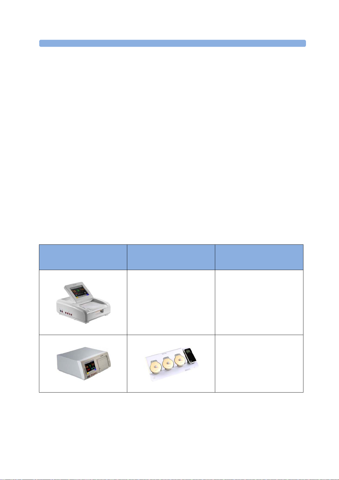
Overview of System Components
The Avalon CL system consists of the Avalon CL base station, the Avalon CL transducers, the
Avalon CL Fetal & Maternal Pod, the CL Wide Range Pod, and the IntelliVue CL Pods.
The IntelliVue CL Pods are only used for maternal measurements within the Avalon CL solution.
The following table provides an overview of all the devices.
Avalon FM20/FM30 and FM40/
FM50
Wired Transducers
FM20/FM30
M2702A and M2703A
FM40/FM50
M2704A and M2705A
Avalon CL Base Station
Avalon CL Transducers
Avalon CL Base Station
866074
CL Pods
18
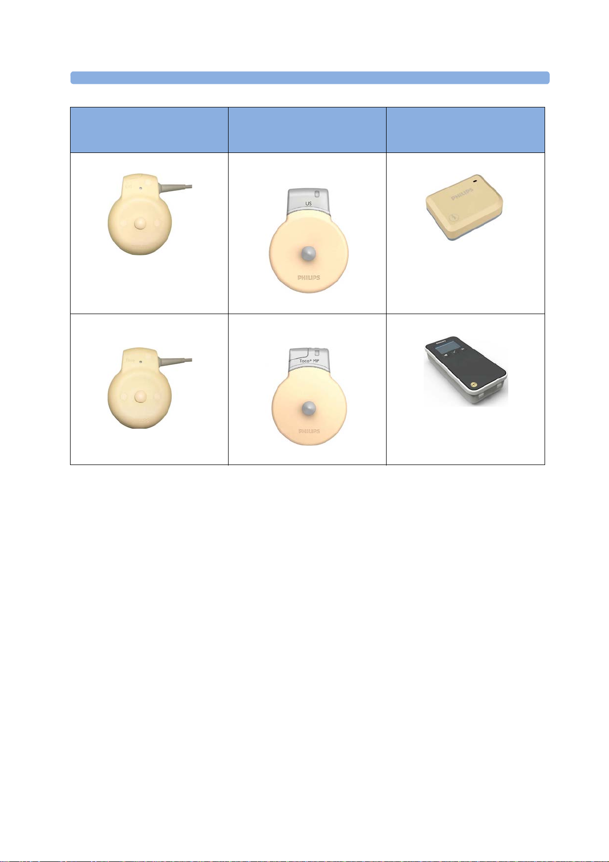
1 Introduction
Avalon FM20/FM30 and FM40/
FM50
Wired Transducers
US transducer (wired)
M2736A
Toco/ Toco MP transducer
(wired)
Avalon CL Base Station
Avalon CL Transducers
Avalon CL US Transducer
(cableless)
866076
Avalon CL Toco+ MP Transducer
(cableless)
CL Pods
Avalon CL Fetal & Maternal Pod
866488
Avalon CL Wide Range Pod
M2734A and M2734B
866487
866075
19
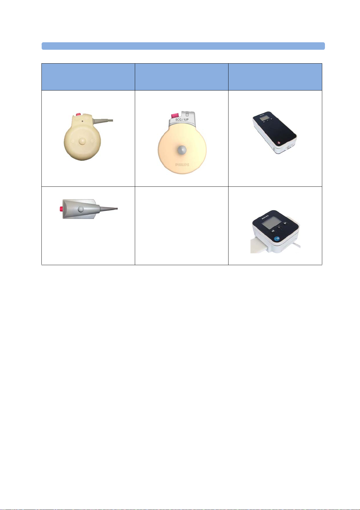
1 Introduction
Avalon FM20/FM30 and FM40/
FM50
Wired Transducers
Toco+ transducer with ECG/IUP
capability (wired)
M2735A
Patient Module for ECG/IUP
M2738A
Avalon CL Base Station
Avalon CL Transducers
Avalon CL ECG/IUP Transducer
(cableless)
866077
CL Pods
IntelliVue CL NBP Pod
(cableless)
865216
IntelliVue CL SpO2 Pod
(cableless)
865215
20

2What's New
aFHR
aHR
aToco
cl F&M Electrode Status
cl F&M Status
This section lists the most important new features and improvements to the fetal monitors and their
user interface introduced with Release L.3.
You may not have all of these features, depending on the fetal monitor configuration purchased.
What's New in Release L.3
Avalon CL Fetal & Maternal Pod
The Avalon CL Fetal & Maternal Pod is an extension of the Avalon CL solution. The Avalon
CL Fetal & Maternal Pod is used together with a single use patch with five abdominal electrodes. Prior
to use, the Avalon CL Fetal & Maternal Pod is charged and assigned at the Avalon CL base station.
The Avalon CL Fetal & Maternal Pod is used with singleton pregnancies. This solution provides
especially benefits to patients with high body mass index (BMI), although it can be used for all patients.
2
The Avalon CL Fetal & Maternal Pod includes the following features:
• The Avalon CL Fetal & Maternal Pod measures fetal heart rate (
and uterine activity (
•The
contact status, when the CL Fetal & Maternal Pod is placed on the electrode patch, and the patch,
and the electrodes are applied to the patient's abdominal skin. The window can be opened by
selecting the new SmartKey
setup menu.
• The Avalon CL Fetal & Maternal Pod and the CL Wide Range Pod are assigned at the CL base
station in the same easy way as the IntelliVue CL Pods.
• The functions Finder LED and Call Patient work also with the Avalon CL Fetal & Maternal
Pod.
See “Avalon CL Fetal & Maternal Pod” on page 21, “CL Fetal & Maternal Electrode Patch” on
page 91, “Applying the CL Fetal & Maternal Patch and Pod” on page 100, and “CL Pod Assignment”
on page 99.
) from electrical signals.
window at the monitor gives an overview of the current electrode
, or selecting the corresponding function in the main
), maternal heart rate (
),
21

2 What's New
Enter Note
Type a note
Avalon CL Wide Range Pod
The Avalon CL Wide Range Pod is an extension of the Avalon CL solution. The Avalon CL Wide
Range Pod extends the signal range of the cableless measurements. It transmits the cableless
measurement signals via the hospital WLAN/WiFi to the fetal monitors. Wearing the CL Wide Range
Pod, the patient can walk freely within the hospital's WLAN/WiFi range during monitoring. Prior to
use, the Avalon CL Wide Range Pod is charged and assigned at the Avalon CL base station.
• A new WLAN symbol is printed on the trace to indicate the use of an assigned and active Avalon
CL Wide Range Pod.
• During monitoring with an active Avalon CL Wide Range Pod, the sound from the fetal heart rate
is replaced by an artificial QRS sound (when the patient is monitored with a CL US transducer or
CL F&M Pod).
See “CL Wide Range Pod” on page 91.
Dawes/Redman
Dawes/Redman is a method of fetal monitoring trace interpretation for helping to assess fetal
well-being. The algorithm based on the Dawes/Redman criteria uses the parameters fetal heart rate,
gestational age, fetal movement, accelerations and decelerations, and long, and short term variability to
generate a report.
Not available in the USA and territories relying on FDA market clearance.
Support of XDS Remote Display
The fetal monitor software supports the IntelliVue XDS “Remote Display” functionality only in
combination with IntelliSpace Perinatal revision K or higher. From the user interface of the
IntelliSpace Perinatal system, you can access all screen-operable functions of the currently connected
fetal monitor. These functions include for example, starting and stopping physiological measurements,
changing measurement modes, changing alarm limits, and silencing alarms.
New Alarm Behavior of CL Battery Empty INOP
The CL <xxx> Battery Empty INOP issued by the CL devices and the fetal monitor has a new alarm
behavior:
• At the fetal monitor, it is issued now with a cyan INOP alarm and tone.
• At CL devices (CL transducers and CL Pods), it is issued now with a tone.
See “Patient Alarms and INOPs” on page 129.
Using CL Pods with FM20/30 #E25
The CL Pods can now also be used with a battery operated FM20 or FM30 (option #E25). The
CL Pods can be assigned and activated. The CL F&M Pod can also be charged.
See “Using Batteries” on page 110.
Entering Notes - Type a Note
In the menu
pre-configured notes. To enter a note, select the new menu item
keypad opens. The typed note can be up to 30 characters long.
See “Typing Notes” on page 70.
, it is now possible to enter a note manually, instead of selecting one of the
. A window with a touch
22

What's New in Release J.3
Avalon CL Transducer System
The Avalon CL Transducer System provides cableless monitoring with the Avalon FM20/FM30 and
FM40/FM50 with the same functionality and performance as the wired measurement devices (e.g.
twin and triplets monitoring). The Avalon CL Transducer System has a straight-forward handling and
operating concept. The CL transducers are assigned by simply docking them at the CL base station, no
further configuration is necessary.
The Avalon CL Transducer System includes the following features:
• Cableless monitoring of twins and triplets (see “Monitoring Twin FHRs” on page 183 and
“Monitoring Triple FHRs” on page 191)
• Cableless maternal measurement Pods CL SpO
page 92)
• Maternal pulse from a CL Toco
Pulse Rate” on page 221)
• A cableless ECG/IUP transducer measuring IUP or fetal/maternal ECG (see “Monitoring
MECG Wave” on page 225 and “Monitoring FHR Using DECG” on page 199)
• Watertight cableless transducers that can be used to monitor in water (see “Underwater
Monitoring” on page 108)
+
MP (Smart Pulse) transducer (see “Monitoring Maternal Heart /
2 What's New
and CL NBP (see “IntelliVue CL Pods” on
2
• Patient call that pages an ambulating mother with an audible signal emitted by the worn CL
transducers (see “Calling Patients” on page 93)
• Out-of-range audible signal emitted by the worn CL transducers to inform an ambulating mother
that she has reached the limit of the active signal area-of-reach (see “Standard Radio Range of CL
Transducers” on page 87)
• A transducer finder LED on all CL transducers to help identify the assigned transducer (see
“Cableless Transducer LED Indication” on page 86)
Support For Use of Maternal Cableless Measurement Devices
The IntelliVue CL measurement Pods are patient-worn, battery-powered measurement devices for
and NBP. The devices provide measurement values on the built-in display and communicate
SpO
2
them to the fetal monitor using the wireless short range radio (SRR) interface of the Avalon CL base
station (see “IntelliVue CL Pods” on page 92).
Maternal Temperature Measurement
To measure maternal temperature, the new optional tympanic thermometer (866149) is available for
the Avalon fetal monitors (“Monitoring Maternal Temperature” on page 249). The measurement data
is:
• documented and printed out at the local recorder, and transmitted to the obstetrical information
and surveillance system.
• displayed as a numeric on the screen.
23

2 What's New
Record on Trace
Send to OB Sys
Start ECG
Record ECG
Call Patient
Tele Info
Tele Info
Tele Info
Enter Temp
NBP Modes
QuickAdmit
Coincidence
Coincidence
Manually Entered Maternal Temperature Measurements
Manually measured temperatures can be entered at the fetal monitor. They are displayed as a numeric
on screen, and are printed out on the recorder trace (“Monitoring Maternal Temperature” on
page 249).
SpO2 Recordings and Transmissions
SpO2 annotation on local recorder
You can now configure the interval for printing the SpO
the new configuration setting
transmission to an obstetrical information and surveillance system
SpO
2
You can now configure the interval for transmitting the SpO
information and surveillance system. With the new configuration setting
interval to 1 or 5 minutes.
New Design for the User Interface
The user interface for the fetal monitors has been redesigned to bring the presented information into
the foreground, letting the structural elements such as keys and frames retreat into the background.
Additionally special regard was given to making the "look and feel" similar to that of standard software
products (see “Operating and Navigating” on page 38).
New SmartKeys
•The
• With the
transducers.
• With the
the
connected Avalon CL base station.
• With the
manually measured maternal temperature values.
• With the
start and stop a measurement.
• With the
All new SmartKeys are optional, and have to be configured in Configuration Mode for use (see
“SmartKeys” on page 42).
SmartKey and menu item is renamed to
SmartKey, you can now page patients who are ambulating wearing Avalon CL
SmartKey, you can call up the
window, you can control and view the status of the cableless transducers from the
SmartKey, a pop-up window opens showing a numeric pad for entering
SmartKey, you can access the NBP Mode selection and setup, and can directly
SmartKey, you can quick admit a patient to the monitor.
numeric values on the recorder trace. With
2
, you can set the interval to 1 or 5 minutes.
numeric values to an obstetrical
2
, you can set the
.
window on the fetal monitor display. In
Coincidence INOP Tone
When the cross-channel verification detects that the signal of the maternal heart rate coincides with the
fetal heart rate, the
INOP tone has a configurable delay see “Cross-Channel Verification (CCV)” on page 159.
24
INOP is now issued with a tone at the fetal monitor. The

Increased Internal Back-up Memory
ECG Leads Off, Cuff Overpress, Cuff NotDeflated, Battery Empty, No
Pulse
The internal back-up memory is now able to store traces and data from at least the last 3.5 hours with
the software revision J.3, and minimum 7 hours with the new mainboard hardware revision A 00.18
(see “Manually Recording Stored Data” on page 258 and “Recovering Data” on page 257).
Dual System Interface Support
If the fetal monitor is connected via a LAN connection to OB TraceVue/IntelliSpace Perinatal, the
RS232 interface can be used independently to connect e.g. an EMR system on read-only basis. The
system connected to the RS232 interface in this case cannot alter any data (such as ADT data, or the
date and time setting), or interfere with functions of the monitor, but is able to read output data. The
obstetrical information and surveillance system connected via LAN has priority.
USB Interface
An optional USB interface allows the use of bar code readers and input devices such as a keyboard, or
mouse (see “Getting to Know Your Avalon FM20/FM30”/“Bottom” on page 32 and “Getting to
Know Your Avalon FM40/FM50”/“Rear” on page 33).
Flexible Nurse Call Interface
An optional Flexible Nurse Call interface allows the connection of a nurse call device to the fetal
monitors (see “Getting to Know Your Avalon FM20/FM30”/“Bottom” on page 32 and “Getting to
Know Your Avalon FM40/FM50”/“Rear” on page 33).
2 What's New
DHCP Support
The DHCP support offers an alternative to BOOTP. DHCP (Dynamic Host Configuration Protocol)
enables the fetal monitors to request an IP address (internet protocol address) from the connected
network (OB TraceVue/IntelliSpace Perinatal) automatically.
Data Export Support
You can now export measurement values from the monitor to other devices via the LAN interface, or
with the optional MIB RS232 interface (see “Getting to Know Your Avalon FM20/FM30”/“Bottom”
on page 32 and “Getting to Know Your Avalon FM40/FM50”/“Rear” on page 33).
NBP Configurable Measurement Sequence
Up to four measurement cycles can be set up which will run consecutively. For each cycle, you can set
the number of measurements and the interval between them. By setting the last cycle to run
continuously, you can have regular measurements continue after the sequence has run (see “Enabling
Sequence Mode and Setting Up the Sequence” on page 240.
Alarms Enhancements
In addition to the standard cyan INOPs, some INOPs can now be configured as red or yellow INOPs
to provide a severity indication (
) (see “Alarms” on page 117).
25

2 What's New
Alarm Reminder
Alarm Reminder
Auto Free
Alarm Reminder
In Configuration Mode, you can set now an
reminder of alarm conditions that remain active after the alarm is acknowledged. This reminder may
take the form of a repetition of the alarm tone for a limited time, or an unlimited repetition of the
alarm tone (this is the same as a new alarm). The interval between silencing the alarm and sounding the
reminder tone can be set to one, two, or three minutes (see “Alarm Reminder” on page 122).
Auto Free
In Configuration Mode, you can now set an
when the fetal monitor has been powered off, or is in standby mode for a set time. Only the
demographic patient data is deleted, the trace data is not affected.
setting which discharges a patient automatically
. The
emits an audible
26
3Basic Operation
This chapter gives you an overview of the monitor and its functions. It tells you how to perform tasks
that are common to all measurements (such as entering data, switching on a measurement, changing
some monitor settings, and setting up the recorder). The alarms section gives an overview of alarms.
The remaining sections tell you how to perform individual measurements, and how to care for and
maintain the equipment.
3
27

3 Basic Operation
Supported Measurements
Different measurements for the same physiological parameter may have a different appearance on the
trace, due to: variability (HR), averaging, delay, amplitude, or artifacts. Before interpreting the trace,
regard the fetal monitor setup and transducers used.
The following Fetal measurements are supported:
Measurements FM20 FM30 FM40 FM50
Fetal Heart Rate (FHR) via
US (including Twins)
Triple FHR via US
dFHR via Direct ECG
(DECG)
aFHR via CL F&M Pod
To co
aToco via CL F&M Pod
Intrauterine Pressure (IUP)
The following Maternal measurements are supported:
Measurements FM20 FM30 FM40 FM50
Maternal Heart Rate (MHR)
via Maternal ECG Electrodes
Maternal ECG (MECG wave)
aHR via CL F&M Pod
Maternal Pulse from Toco
Standard Standard Standard Standard
Optional Optional Optional Optional
- Standard - Standard
Optional Optional Optional Optional
Standard Standard Standard Standard
Optional Optional Optional Optional
- Standard - Standard
Standard Standard Standard Standard
- Standard - Standard
Optional Optional Optional Optional
Standard Standard Standard Standard
Noninvasive Blood Pressure
with Pulse Rate
Pulse Oximetry (Maternal
SpO
) with Pulse Rate
2
Maternal Temperature
28
Optional Optional Optional Optional
Optional Optional Optional Optional
Optional Optional Optional Optional
Avalon FM20 and FM30
This section outlines the capabilities of your monitor.
3 Basic Operation
Avalon FM20
The Avalon FM20 fetal/maternal monitor provides a solution for external fetal monitoring
applications, and optional noninvasive maternal vital signs.
You can monitor fetal heart rates (FHRs) externally using ultrasound, uterine activity and maternal
pulse using an external Toco transducer, and the maternal heart rate (MHR) with maternal ECG
electrodes, and optionally, noninvasive blood pressure and maternal oxygen saturation (SpO
Measurements are displayed on a 6.5 inch color display as numerics. The display is a touchscreen, and
you operate the monitor using this touchscreen interface. The integrated recorder documents fetal and
maternal measurements as well as the user-defined annotations.
You can connect the monitor to an OB TraceVue/IntelliSpace Perinatal system via the RS232
connection, or over a LAN connection (with OB TraceVue Revision E.00.00 and later, or IntelliSpace
Perinatal Revision H.0 and later).
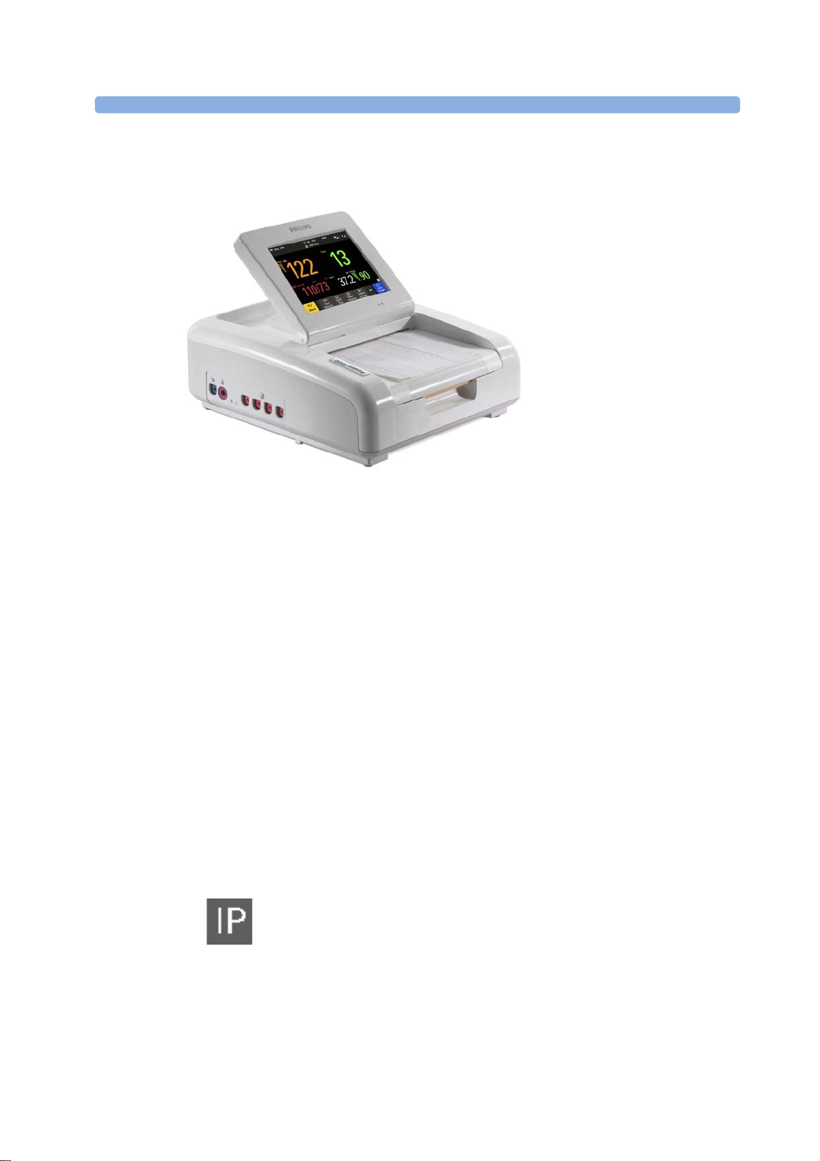
Avalon FM30
The Avalon FM30 fetal/maternal monitor offers a solution for both external and internal fetal
monitoring applications, and optional noninvasive maternal vital signs.
The Avalon FM30 shares all the features and capabilities of the Avalon FM20. In addition, you can
monitor one FHR internally with a direct fetal electrocardiogram (DECG), uterine activity internally
using an intrauterine pressure (IUP) catheter together with a Toco
The Avalon FM30 carries the IP label, indicating that it is capable of intrapartum monitoring.
2
+
transducer or patient module.
).
29
3 Basic Operation
FM20/30 with
Battery
Option #E25
The battery option for the FM20/30 provides support for the in-transport monitoring of all
measurements when disconnected from a power supply. Existing data storage is automatically
uploaded to OB TraceVue or IntelliSpace Perinatal after reconnecting it to the system. Trace printing
Only
during transport is also possible.
Avalon FM40 and FM50
This section outlines the capabilities of your monitor.
Avalon FM40
The Avalon FM40 fetal/maternal monitor provides a solution for external fetal monitoring
applications, and noninvasive maternal vital signs.
You can monitor fetal heart rates (FHRs) externally using ultrasound, uterine activity using an external
Toco transducer, and the maternal heart rate (MHR) via maternal ECG electrodes, and noninvasive
blood pressure and maternal oxygen saturation (SpO
Measurements are displayed on a 6.5 inch color display as numerics. The display is a touchscreen, and
you operate the monitor using this touchscreen interface. The integrated recorder documents fetal and
maternal measurements as well as the user-defined annotations.
You can connect the monitor to an OB TraceVue/IntelliSpace Perinatal system with the RS232
connection, or over a LAN connection (with OB TraceVue Revision E.00.00 and later, or IntelliSpace
Perinatal Revision H.0 and later).
).
2
30

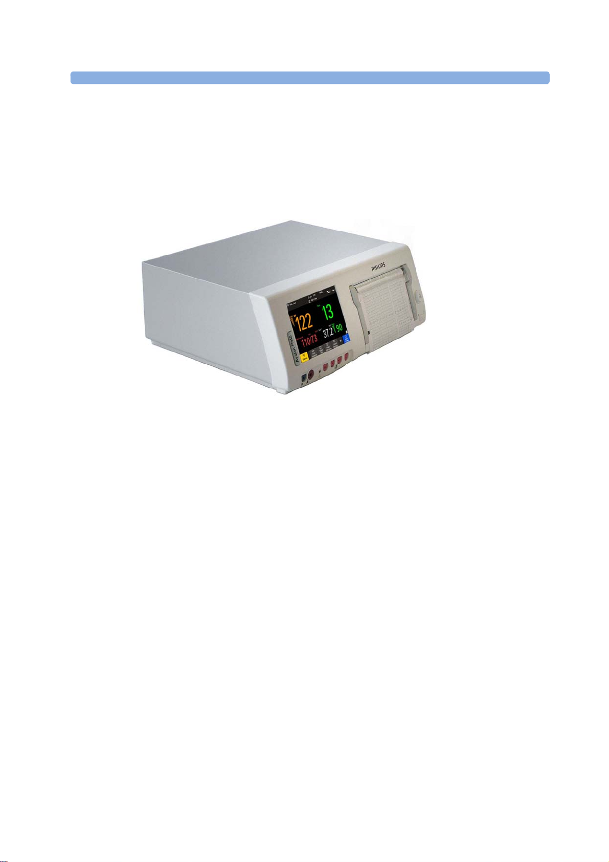
Avalon FM50
The Avalon FM50 fetal/maternal monitor offers a solution for both external and internal fetal
monitoring applications, and noninvasive maternal vital signs.
The Avalon FM50 shares all the features and capabilities of the Avalon FM40. In addition, you can
monitor one FHR internally with a direct fetal electrocardiogram (DECG), and uterine activity
+
internally using an intrauterine pressure (IUP) catheter together with a Toco
module.
The Avalon FM50 carries the IP label, indicating that it is capable of intrapartum monitoring.
transducer or patient
Getting to Know Your Avalon FM20/FM30
Overview
1 Touchscreen display (tilt and fold)
3 Basic Operation
Right Side
2 Power LED
3 Paper drawer
4 Paper drawer release
5 Connectors
1 On/Off switch
2 Power connector
31

3 Basic Operation
with Battery
Option
Left Side
1 On/Standby button with power LED
2 MSL connector for external power
supply
Bottom
1 SpO
2 Noninvasive Blood Pressure
3 Fetal sensor sockets
Each of the fetal sensor sockets accepts any fetal transducer, one Avalon CL or one Avalon CTS
Cableless Fetal Transducer System base station, or an event marker.
There are five optional interfaces available for the Avalon FM20/30 monitor:
• LAN/RS232 system interface
• Dual PS/2 interface
• Dual MIB/RS232 interface
• Flexible Nurse Call interface
• USB ports interface
socket (optional)
2
socket (optional)
32

You can use two of the five optional interfaces at the same time.
Optional Interfaces Description
Flexible nurse call interface card
Quad. USB ports
3 Basic Operation
1 LAN/RS232 system
interface
2 Dual PS/2 system
interface
Rear
Dual MIB/RS232
1 Display release
2 Carrying handle
3 Built-in stand
33

3 Basic Operation
Getting to Know Your Avalon FM40/FM50
Front
1 Touchscreen color display
2 Transparent paper guide with tear-off
edge
3 Paper eject button
4 Power LED
5 On/Standby button
6 Recorder paper table
7 Fetal sensor sockets
8 Noninvasive blood pressure socket
(optional)
9 SpO
socket (optional)
2
Connect any fetal sensor or patient module at the fetal sensor sockets, including an Avalon CL or an
Avalon CTS via interface cable (with red connector).
34

Rear
3 Basic Operation
1 Reserved for future use: protective
earth intended for use in system
installations
2 Equipotential grounding point
3 Power cord connector
4 Loudspeaker
5 Slot 01 for optional LAN/RS232
system interface (for connection to an
obstetrical information and
surveillance system)
6 Slot 03 reserved for future use
7 Video output (VGA)
8 Telemetry interface
9 Slot 02 for optional interfaces: Either
dual PS/2 system interface (A) for
mouse and keyboard connection) Or
MIB interface (B) for external
touchscreen connection, or the
optional interfaces for the flexible
nurse call or USB ports
Two Avalon CL base stations, or one Avalon CTS can be also connected to the Telemetry interface
sockets using the interface cable (with black connector).
Additional Optional Interfaces
Optional Interfaces Description
Flexible nurse call interface card
Quad. USB ports
Dual MIB/RS232 interface
35

3 Basic Operation
Global Settings
Connecting the Monitor to AC Mains
WARNING
• Always use the supplied power cord with the earthed mains plug to connect to an earthed AC
mains socket. Never adapt the mains plug from the fetal monitor to fit an unearthed AC mains
socket.
• Check that the line frequency is correctly configured in the
• FM20/FM30 only: The protective earth conductor is required for EMC purposes. It has no
protective function against electric shock. Double and/or reinforced insulation protects this
device against electric shock.
• Do not use AC mains extension cords or multiple portable socket-outlets.
Always ensure that the monitor is positioned so that the AC mains plug is easily accessible, to allow
disconnection of the monitor from the AC mains.
Wired Transducers
menu.
1 Transducer finder LED - lights up
on the transducer supporting to
identify the measurement source
2 "MP" for M2734B "Toco MP"
transducers (additionally capable
of providing the maternal pulse
measurement)
3 Belt button
36
Toco (M2734A) and Toco MP Transducer (M2734B)

Ultrasound Transducer (M2736A)
3 Basic Operation
1 Cable - connects to any of the
four fetal sensor sockets on the
monitor
The M2736AA US transducer is
identical to the M2736A US
transducer, including all specifications
1 Connector - for connecting
ECG/IUP adapter cables
(M2735A Toco
+
transducer only)
+
Transducer with ECG/IUP capability
Toco
(M2735A)
Patient Module for ECG/IUP (M2738A)
1 Butterfly belt clip (shown fitted;
for use with belts without button
holes)
2 Close-up of MECG adapter cable
connected to Toco
3 Close-up of active finder LED
1 Connector - for connecting ECG/
+
transducer
IUP adapter cables (same as for
+
transducer)
Toco
2 Cable - connects to any of the four
fetal sensor sockets on the monitor
37

3 Basic Operation
Operating and Navigating
Your monitor has a touchscreen. Everything you need to operate the monitor, except the on and off
switch, is contained on its screen. Most screen elements are interactive. Screen elements include
measurement numerics, screen keys, information fields, status indicators, alarms fields, and menus.
Operator Position
The typical operator's position is in front of the monitor.
FM40/50 If an optional external touch display is connected to the monitor, you can operate the monitor using
the external touch display.
1 Monitor
information line
2 Measurement area
3 Key area
38
CAUTION
The screen contains sensitive personal data. For information how to protect personal information, see
“Protecting Personal Information” on page 17.

Screen Elements
Monitor Information Line
1 LAN connection status indicator only. RS232 system connection is not indicated. The
locomotive icon indicates if the fetal monitor is connected to OB TraceVue/IntelliSpace
Perinatal, via a LAN cable or not.
2 Patient identification
3 Date and time
4 Bed label (when connected to a Philips OB TraceVue/IntelliSpace Perinatal system)
5 Fetal heart sound volume adjust/indicator
6 Alarm volume adjust/indicator
7 INOP and alarm status area - shows active alarm messages
3 Basic Operation
39

3 Basic Operation
Measurement Area
1 Antenna symbol (indicates a cableless measurement from a connected Avalon CL or Avalon CTS
system)
2 Configurable alarm limits
3 NST test
4 Audio source symbol
5 Measurement numeric
6 Alarms off symbol
7 Fetal trace recorder - status indicator
8 Avalon CL or Avalon CTS system - status indicator
9 Battery status indicator
10 Status line - shows status and prompt messages
11 Signal quality indicator: good, acceptable, poor
12 Fetal heart rate measurement label
13 Measurement unit (configurable)
14 Coincidence symbol (see “Cross-Channel Verification (CCV)” on page 159)
15 NST timer, if configured (default is Off)
40

Screen Details
Paper Save Mode
Paper Save Mode
CL
Main Screen
Silence
Icon Description
3 Basic Operation
The antenna symbol indicates a cableless measurement
(Avalon CL or Avalon CTS).
Indicates a short range radio measurement (CL Pods).
Signal quality indicator:
1 Good
2 Acceptable
3 Poor
Fetal trace recorder - status indicator
Fetal recorder is on
Fetal recorder is off (when
is off)
Key Area
Fetal recorder is off (when
There is a user-solvable recorder error (paper out, paper jam,
wrong paper scale set)
Fetal recorder is defective: call service
When an Avalon CL or Avalon CTS system is connected to the
monitor, a
symbol is shown. It changes with the states of the
connected cableless device see “Cableless Status Indication” on
page 95.
1 SmartKeys - these can vary according to your monitor's configuration
2
- closes all open menus and windows and returns to main screen
is on)
3 Scroll to display more SmartKeys
4
- acknowledges all active alarms by switching off audible alarm indicators
41

3 Basic Operation
Silence
Main Screen
FRStart/Stop
Start Rec
Stop Rec
Paper Advance
Set Marker
Enter Notes
Record ECG
Stored Rec
NST Report
Sound Vol. Up
Sound Vol. Down
Toco/IUP Bsl
Tele Info
Tele Info
Keys
The monitor has three different types of keys.
Permanent Keys
A permanent key is a graphical key that remains permanently on the screen, giving you fast access to
functions.
Key Name Function
Acknowledges all active alarms by switching off audible
alarm indicators.
Closes all open menus and windows and returns to the
main screen.
SmartKeys
SmartKeys are configurable graphical keys, located at the bottom of the main screen. They give you
fast access to functions. The selection of SmartKeys available on your monitor depends on your
monitor configuration, and on the options purchased.
SmartKey Name Function
Turns the trace recorder on or off
Turns the trace recorder on
Turns the trace recorder off
Advances the paper automatically to the next fold
Marks an event
Enters notes
Starts printing the MECG, DECG, or both waves, when
both are available
Prints trace data from the monitor's memory
42
Initiates an NST trace interpretation and obtains a Nonstress test (NST) report
Increases the fetal heart rate volume
Decreases the fetal heart rate volume
Resets Toco baseline
Calls up the
window

Call Patient
cl F&M Status
cl F&M Electrode Status
Pause Alarms
Alarms Off
Defaults
Main Setup
Strt/Stp NBP
Start NBP
Stop NBP
Stop All NBP
Repeat NBP
NBP Modes
Enter Temp
Zero IUP
Timer
Standby
Patient Demogr.
QuickAdmit
Blank Key
SmartKey Name Function
Pages the patient. Only enabled if at least one
CL transducer is currently active
Calls up the
3 Basic Operation
window
Enters main setup menu
Pauses alarm indicators. Pause duration depends on
monitor configuration. If the pause duration is infinite, this
key is labeled
Select again to immediately re-enable alarm indicators
Loads User Default
Starts/stops manual noninvasive blood pressure
measurement
Starts auto series
Stops current automatic measurement within series
Starts manual noninvasive blood pressure measurement
Starts auto series
Stops manual noninvasive blood pressure measurement
Stops current automatic measurement within series
Stops all noninvasive blood pressure measurements
Sets the time interval between two noninvasive blood
pressure measurements
Access NBP mode selection and setup, with direct start/
stop function
Allows the manual input of the patient's temperature
Resets the display and trace to 0. If you do not zero the IUP
measurement properly, the pressure trace may exceed the
paper scaling.
Enters NST timer window
Switches to standby screen, suspends monitoring. All
numerics and waves disappear from the display. All settings
and patient data information are retained
Enters the patient identification menu to admit/discharge
Quick admits the patient for monitoring
Blank key, can be used as divider between a group of keys
43

3 Basic Operation
Confirm
Main Screen
Main Screen
Main Screen
Main Setup
Operating Modes
Pop-Up Keys
Pop-up keys are context-sensitive graphical keys that appear automatically on the monitor screen when
required. For example, the
pop-up key appears when you need to confirm a change.
Using the Touchscreen
Select screen elements by pressing them directly on the monitor's screen.
Disabling Touchscreen Operation
1 To temporarily disable the touchscreen operation of the monitor, press and hold the
permanent key for about three seconds. A red padlock will blink on the
key.
2 Press and hold the
touchscreen operation.
permanent key again for about three seconds to re-enable the
Operating Modes
When you switch on the monitor, it starts up in Monitoring Mode. To change to a different mode:
1 Select the
2 Select
Your monitor has four operating modes. Some are passcode protected.
Mode Description Password
menu.
and select a mode.
permanent
Protected
44
Monitoring Mode The Monitoring Mode is the normal operating mode to
monitor patients. You can change elements such as alarm
limits. When you discharge the patient, these elements
return to their default values.
You cannot select or change grayed out items. These items
are for your information only. To change these items,
switch to the Configuration Mode.
Demo Mode The Demo Mode is used for demonstration and training
purposes. Do not change into Demo Mode during
monitoring. When transducers are connected to the
monitor and the recorder is on, a demo trace is recorded.
But the demo trace is not transmitted when the fetal
monitor is connected via RS232 to an information and
surveillance system such as OB TraceVue/IntelliSpace
Perinatal.
no
yes

3 Basic Operation
Mode Description Password
Protected
Configuration Mode The Configuration Mode is for personnel trained in
configuration tasks. You can change and store the default
values and patient profiles permanently in the
Configuration Mode. These tasks are described in the
Configuration Guide. During installation, the fetal
monitor is configured for use in your environment. This
configuration defines the default settings you work with
when you switch on the fetal monitor.
Service Mode The Service Mode is for trained and authorized service
personnel only.
A field displayed at the fetal monitor screen indicates if the monitor is in Demonstration Mode,
Configuration Mode, or Service Mode. To change to a different mode, select this field.
Automatic Screen Layouts
Your monitor's preconfigured screen layouts define how measurement information is arranged on the
screen. The monitor automatically applies the correct screen layout for the measurements you are
monitoring. No user action is required.
Connecting or disconnecting transducers, or activating or deactivating a cableless measurement, results
in an automatic adjustment of the screen layout. When a measurement is off, its numerics are removed
from the monitor's screen. The monitor stops acquiring data and generating alarms for this
measurement. If you disconnect a transducer while it is performing a measurement, the monitor issues
a disconnect INOP (and in the case of SpO
mark).
2
yes
yes
, replaces the measurement numeric with a question
Settings
This section describes the various settings available on the monitor.
Active Settings
What the monitor displays, and the way it operates, is controlled by its settings. They determine sound
volume settings, recorder settings, high and low alarm limits and so forth.
The "active settings" are the current settings the monitor uses, including any adjustments made by the
last user. Active settings are not permanent, but are retained after a loss of mains power.
There are also two preconfigured default settings:
•User Default
• Factory Default
45

3 Basic Operation
User Defaults
User Defaults
User Defaults
Defaults
Confirm
User Defaults
Factory Defaults
Factory Defaults
Factory Defaults
Factory Defaults
User Defaults
Global Settings
User Defaults
Global Settings
Setup FHR1
FHR1
Main Setup
Main Setup
Measurements
User Default
The
store the active settings, modified to your preference, in the
are a complete configuration stored in the monitor's long-term memory. You can
(in Configuration Mode).
In Monitoring Mode, you can load the
1 Select the
2 Select
Factory Default
The
SmartKey.
in the dialog box to load the
is a complete configuration predefined at the factory. You cannot modify it. In
Configuration Mode, you can load the
CAUTION
This resets all settings to factory defined values, but be aware that some values will differ from those
with which the fetal monitor was originally shipped from the factory (recorder speed and paper scale
type will need to be corrected, for instance). After loading the
if necessary, change them to the settings you normally use.
You can use the
as the basis for producing your
Guide for details.
Global Settings
General monitor configuration settings are stored in the
frequency, QRS type, and whether the monitor is automatically reset to the
interruption of more than one minute. You can change the
Changing Measurement Settings
Each measurement has a setup menu in which you can adjust all of its settings. You can enter a setup
menu:
settings to return to your preferred settings:
.
as the active settings.
, check the settings, and
. See the Configuration
. These include settings for line
after a power
in Configuration Mode.
46
1 with the measurement numeric - select the measurement numeric on the screen to enter its setup
menu. For example, to enter the
2 with the
switched off, use the
name from the pop-up list. With this SmartKey you can access any setup menu in the monitor.
This guide always describes the entry method using the measurement's setup menu. You can use the
method you prefer.
SmartKey - if you want to set up a measurement when the measurement is
SmartKey and select
menu, select the
(fetal heart rate 1) numeric.
. Then select the measurement

Changing Monitor Settings
Main Setup
User Interface
Main Setup
User Interface
Brightness
Optimum
Alarm Volume, QRS Volume
Timer Volume
Main Setup
User Interface
Audio Volumes
Date,
Time
Year, Month, Day, Hour
Minute
.
Store Date, Time
To change monitor settings such as brightness, or touch tone volume:
3 Basic Operation
1 Enter the
2 Select the setting you want to change, or select
menu.
change user interface settings.
Adjusting the Screen Brightness
1 Enter the
2 Select
3 Select
4 Select the appropriate setting for the screen brightness. 10 is the brightest, 1 is the least bright.
Adjusting Audio Volume
is suitable for most situations.
Here you can adjust the audio volume for
audio volume:
1 Enter the
menu.
.
.
menu.
to enter a sub menu where you can
, and
. To adjust an
2 Select
3 Select
loudest and 1 is the quietest. Selecting zero switches the volume off.
Setting the Date and Time
The current date and time is displayed in its own element in the information line of the monitor screen.
1 Select the date and time screen element from the monitor's information line to enter the
menu.
2 Select, in turn, the
3 Select
WARNING
Do not change the date and time setting, if the fetal monitor is connected to a Philips OB TraceVue/
IntelliSpace Perinatal system. The monitor uses the OB TraceVue/IntelliSpace Perinatal system date
and time, including daylight saving time changes. As long as the fetal monitor is connected to the OB
TraceVue/IntelliSpace Perinatal system via the LAN-setup (locomotive symbol displayed on the
monitor's screen), the option to change the date and time settings at the fetal monitor are disabled, this
is not valid for RS232 connections, or the connection to other systems.
.
, then select one of the volume types, and select an audio level. 10 is the
(in 24 hour format), and
, as necessary
to change the date and time.
47

3 Basic Operation
Main Setup, Revisions
Monitor Revision
Monitor Revision
Selftest: OK
Auto Start
On
When disconnected from AC power, the monitor retains the date and time setting for at least two
months. If the monitor is off longer than two months, and the operating system detects that the date
and time settings are invalid, the monitor initiates a "cold" start and sets the date to 1 Jan 1997 and the
time to 00:00.
Checking Your Monitor Revision
1 Select
2 From the
information.
to open the
menu, select the monitor component for which you need revision
Preparing to Monitor
Confirm fetal life before you begin fetal monitoring. Familiarize yourself with the basic operation
principles before you start to monitor.
CAUTION
Check the fetal monitors housing for damage before you start to monitor as part of your safety
precautions.
menu.
After you switch on the monitor:
1 Check that you have the correct patient cables and transducers plugged in for the measurement
you want to monitor.
2 If you use an Avalon CL or Avalon CTS system, check if the cableless transducers are ready and
charged (apparent by either a lit up green or yellow LED indicator).
3 Admit your patient to the monitor (see “Admitting a Patient” on page 147).
4 Check that the alarm limits, alarm and fetal heart rate volumes, patient category, and so forth, are
appropriate for your patient. Change the settings if necessary.
5 Refer to the appropriate measurement section for details of how to perform the measurements
you require.
6 Start recording.
There is no special emergency access for the Avalon Fetal monitors. For all clinical use cases according
the Intended Use, the monitors are taken into operation by connecting them to AC mains and by
switching them on.
Switching On: FM20/FM30
1 Connect the monitor to AC mains and switch the monitor on.
– The green power-on LED lights up.
– The monitor performs a self-test as it starts up.
for the software and firmware are printed on the fetal trace paper (if recorder
).
Battery
Option
configured to
– The monitor display comes on.
– There is a start-up tone from the loudspeaker.
• If this option has been chosen, the green power-on LED on both the external power supply and
the battery LED indicator will light up.
, the serial number, and revisions
is
48

Switching On: FM40/FM50
Selftest: OK
Auto Start
On
1 Connect the monitor to AC mains.
– The green LED lights up.
2 Press the On/Standby switch.
– The monitor performs a self-test as it starts up.
for the software and firmware are printed on the fetal trace paper (if recorder
configured to
).
– The monitor display comes on.
– There is a start-up tone from the loudspeaker.
Adjusting the Display Angle (FM20/FM30)
You can tilt the display on the FM20 and FM30 to one of five different positions, or you can fold it
completely down. The tilt/fold mechanism works on a one-way ratchet system. You hear a click as
each of the five positions is reached. The screen can be folded back down only after tilting the display
forwards as far as it will go.
To tilt the display from the folded position:
1 Unlock the display by releasing the catch.
3 Basic Operation
, the serial number, and revisions
is
2 Lift the display forward. You will hear a click as the first position engages. If you want to tilt the
display further, lift the display further forward until you reach the desired angle.
49

3 Basic Operation
3
4 Then push the display all the way back until it clicks shut.
To fold the display, pull the display forwards as far as it will go.
If your monitor is wall-mounted, the display should be folded flat.
Fastening Belts and Transducers
You can use more than one belt if, for example, you are monitoring uterine activity and FHR
simultaneously. There are two basic ways to fasten belts and transducers:
• Belts with button fixings.
• Velcro belts together with the butterfly belt clip.
What You Need
• Ultrasound transducer
• Toco MP or CL Toco
• Ultrasound gel
• Transducer belt (and optional butterfly belt clip, if applicable)
50
+
MP transducer

Using Belts with Button Fixings
1 Place the transducer belt across the bed, so that the fixing button will face away from the mother
when it is fastened.
2 Lie the patient on the bed and arrange the belt around her until it is tight but still comfortable.
3 Fasten the belt by pushing the fixing button through the overlapping section of the belt. Ensure
that the fixing button and the loose ends of the belt are at the patient's side.
3 Basic Operation
4 When you have positioned a transducer satisfactorily, you can attach it to the belt by pushing the
belt button on the transducer through one of the holes in the belt.
51

3 Basic Operation
5
Alternatively, attach the butterfly belt clip to the transducer belt button and use this to attach the
transducer to the belt. The clip allows you to slide the transducer for easy repositioning.
Using Belt with Velcro Fixings
Insert one end of the belt between the belt guides on one side of the butterfly belt clip, and secure with
the velcro fixing. Insert the other end of the belt between the belt guides on the other side of the
butterfly belt clip, adjust for the correct tension, then secure with the velcro fixing.
1 Velcro fixing
2 Belt guides
3 Velcro fixing
52
WARNING
When connecting devices for acquiring measurements, always position cables and NBP tubing
carefully to avoid entanglement or potential strangulation.

Repositioning Transducers
A patient possibly wears transducers for long periods without interruption. In rare cases, skin
irritations may occur if a transducer is attached to one location for a longer period. To ensure there are
no adverse effects on the patient's skin, inspect the transducer application site at least every three
hours. If the skin quality changes, move the transducer to another site.
The ultrasound transducer is often repositioned to follow the fetal heart as part of the normal
monitoring process, but this is not so for the Toco transducer. Therefore, remember to check its
application site (between contractions) at least every three hours.
To reduce the risk of skin irritations, do not allow a cleaning or disinfecting agent to remain on the
transducer. Follow all instructions that accompany the specific cleaning and disinfecting agents you are
using. Remove agent residues with a cloth dampened in water before applying a transducer to a patient.
See “Care and Cleaning” on page 261 for further information, and a list of approved agents.
Connecting a Transducer to the Monitor
3 Basic Operation
1 SpO
2 Noninvasive blood pressure socket
3 Fetal sensor sockets
socket
2
You can plug a fetal transducer, an ECG/IUP patient module, an Avalon CL or
Avalon CTS Cableless Fetal Transducer System interface cable (red connector), or
an external event marker into any of the four fetal sensor sockets marked by the
fetal symbol, or "Fetal Sensors" (depending on geography).
For measuring maternal SpO2, connect the sensor to the socket marked with the
SpO
symbol or "SpO2" (depending on geography).
2
For maternal noninvasive blood pressure, connect the cuff to the socket marked
with the NBP symbol or "NBP" (depending on geography).
53

3 Basic Operation
FHR1
FHR2
FHR3
For the FM20 and FM30, you can connect an Avalon CL or Avalon CTS Cableless Fetal Transducer
system interface cable (red connector) to one of the fetal sensor sockets at the left side of the monitor.
For the FM40 and FM50, you can connect an Avalon CL or Avalon CTS Cableless Fetal Transducer
System interface cable (black connector) to one of the two dedicated black sockets marked "Tele" at
the rear of the monitor, as an alternative to using one of the fetal sensor sockets (red connector) at the
front.
What You See on the Monitor
When you connect a transducer or sensor, the measurement numeric appears on the screen.
1 Interface cable to Avalon CL and
Avalon CTS Cableless Fetal
Transducer System.
2 Connect the black connector to one
of the two black sockets (marked
"Tele") on the rear of the monitor.
54
FM20/FM30 FM40/FM50
Fetal heart rate measurements are labeled in the order in which you plug in the transducers for those
measurements. It does not matter which fetal sensor socket you use, as the monitor allocates a channel
automatically. For instance, when monitoring triplets, the first transducer you connect is automatically
allocated a channel, and the measurement is labeled
, the second
, and the third
. See
also chapters “Monitoring Twin FHRs” on page 183 and “Monitoring Triple FHRs” on page 191.
When you touch a measurement numeric on the screen, the setup menu for that measurement opens.
The fetal sensor socket to which the transducer for this measurement is connected is identified by the
transducer position indicator in the setup menu header.

3 Basic Operation
Scale Type (US
Internat'l
Fetal
Recorder
The blue finder LED on a wired fetal transducer lights up when you touch the measurement on the
screen, allowing you to identify the corresponding transducer.
1 finder LED
The white finder LED on a cableless fetal transducer lights up when you touch the measurement on
the screen, allowing you to identify the corresponding transducer.
The recorder prints an annotation showing the date, time, recorder speed, and Monitoring Mode. It
repeats this every 10 minutes.
Start Recording
Checking/Setting Paper Scale
You can check the paper
menu. In Monitoring Mode, you can see these settings (grayed out), but you cannot change
them. They can be changed in Configuration Mode, see the Configuration Guide.
NOTE
Check if the scale type of the paper and the settings in the fetal monitor match.
for USA, or
1 finder LED cableless transducer
for other geographies) in the
55

3 Basic Operation
Main Setup
Fetal Recorder
Start/ Stop
Start Recordng
Selftest: OK
Paper Guide FM40/FM50
The recorder in the FM40 and FM50 features a transparent paper guide which:
• facilitates correct alignment of the paper, both during loading and while the recorder is running.
See “Loading Paper FM40/FM50” on page 65.
• incorporates a tear-off edge, which not only allows you to tear off the trace paper where you like
(not necessarily at a fold), but also helps to avoid paper misalignment while doing so (see “Tearing
Off the Paper” on page 61).
• is removable (see “Removing the Paper Guide: FM40/FM50” on page 269).
Switching the Recorder On and Off
In addition to the normal recording of real-time traces, you will sometimes see a trace recovery
printout from the monitor's internal backup memory at high speed when the recorder is started. For
details, see “Recovering Traces on Paper” on page 257.
For an explanation of the various symbols that can appear on the trace recording, see “Recorder
Specifications” on page 308.
To switch the recorder on, select in
SmartKeys:
or
.
the menu item
, or press one of the
The "recorder on" status indicator is displayed in the bottom right-hand corner of the screen when you
switch on the recorder.
The paper advances quickly for 2 cm and then returns to the set speed. Whenever the recorder is
switched on, a trace header is printed vertically on the trace paper, containing the following:
•
: confirmation that the monitor's self-test completed successfully, and that it is ready to
use
• the software revision and firmware revision
• the serial number
• the time
• the date
• patient name and medical record number (if entered)
56
• the recorder speed

3 Basic Operation
1 Fetal heart rate label
2 Uterine activity label
The current monitoring modes (if any transducers are connected to the monitor) are printed.
Whenever a transducer's mode is changed, the following are printed:
• the time
• the date
• trace identification symbols
• the recorder speed
The monitor prints the time, date, recorder speed, and monitoring modes in the trace header when
first switched on, in a periodic time stamp every ten minutes after, and if the monitoring modes
change. The time stamp begins with the symbol shown below. The data is reprinted in the header if the
time and date are locally adjusted, or if an obstetrical information and surveillance system is connected
that readjusts the time and date automatically.
57

3 Basic Operation
Start/Stop
Fetal Recorder
Start/ Stop
Stop
Recordng
Confirmed Stop
Paper Save Mode
Off
Paper Save Mode
The trace records maternal parameters also. When measuring noninvasive blood pressure, the
annotation is made at the end of the measurement. If the noninvasive blood pressure measurement
repetition time is short, the noninvasive blood pressure numeric may not always be printed.
1 Time stamp printed every ten
minutes
The recording of notes (see “Entering Notes” on page 69) or time/date information may be
interrupted by connecting, or unplugging a transducer, or by a change in measurement-related setting
(for example, artifact suppression, Toco sensitivity, or alarm settings).
A new patient admission or a change to the paper scale setting stops all annotations, and prompts a
new vertical trace header to be printed.
To switch off the recorder:
1 Either select
2 Or press one of the SmartKeys (depending on configuration): fetal recorder
from the
menu.
or
.
If your recorder is configured with
need to confirm that you want to stop the recorder, before it will stop.
on (a Configuration Mode setting), you will
When the recorder is off, the "recorder off" status indicator is displayed in the bottom right-hand
corner of the screen: When the
and when
is On the icon shows a paper trace icon.
is set to
the paper symbol shows an x mark,
58

Recording Elements
A variety of information can appear on the recorder trace. Here is a sample trace with some of the
most common elements and their meaning. Each trace header contains the last name and first name,
the patient ID, patient date of birth, the current date and time, patient's bed label, and the gestational
age of the pregnancy.
3 Basic Operation
1 Name, patient ID, date of birth, current date and time
2 Recorder speed
3 Gestational age and patient bed label
4 FMP - Fetal Movement Profile
5 Other measurements for the patient such as temperature, arterial oxygen saturation, and pulse
6 Entered notes such as patient repositioned, or MD notified, or others
7 Time stamp
8 Trace separation
9 Recorder speed
10 Maternal ECG
11 Direct ECG
12 Coincidence of heart rate detected
13 HR with Alarms Off symbol
14 Alarm Limits
15 dFHR2 (second fetal heart rate from DECG)
16 FHR1 (first fetal heart rate)
59

3 Basic Operation
Paper Advance
Fetal Recorder
Set Marker
Caution
The trace contains sensitive personal data. For information how to protect personal information, see
“Protecting Personal Information” on page 17.
Choosing Recorder Speed
You can choose a recorder speed of 1, 2, or 3 centimeters per minute (cm/min). The default setting is
3 cm/min.
The ACOG technical bulletin on FHR monitoring states that "accurate pattern recognition is difficult if not
impossible at 1 cm/min and that 1 cm/min is only recommended for more economic screening. When FHR
abnormalities arise, the faster recorder speeds will enhance FHR pattern recognition".
Additionally, because a change in recorder speed results in a change in the appearance of an FHR trace,
you are advised to ensure ALL monitors in your institution are set to the same speed.
To set the recorder speed (in Configuration Mode), see the Configuration Guide.
Advancing the Paper
You can advance the paper automatically to the next fold by pressing the
any time except during a stored data recording. This is also possible using the
SmartKey at
menu.
Marking an Event
You can record significant events on the trace paper (for example, when pain medication is
administered or when the mother changes position). The mother can use the remote event marker to
mark events herself. You connect the remote event marker to any free fetal sensor socket.
To mark an event on the trace paper, you can:
1 Either select the
2 Or press the button on the optional remote event marker (989803143411). The remote event
marker is connected to the monitor via any fetal transducer socket.
SmartKey.
60

3 Basic Operation
Start/ Stop
Stop Recordng
A small arrow is printed on the heart rate scale on the trace paper.
This reflects exactly when the marker button was first pressed; keeping the button pressed has no
influence on the annotation.
Tearing Off the Paper
CAUTION
Never pull on the paper to advance it, as this can cause misalignment of the paper. Always tear off the
paper along the perforation.
FM40/FM50 The recorder's paper guide incorporates a tear-off edge, allowing you to tear off the trace paper cleanly
where you like (not necessarily at a fold). When you are not using the paper guide, always tear off the
paper along the perforation.
To tear off the trace paper after monitoring using the paper guide:
1 If the recorder is running (the "recorder on" status indicator is displayed), turn off the recorder by
selecting the fetal recorder
2 Tear off the paper as shown in the picture. To ensure a clean tear, always tear in an upwards
motion, as indicated by the arrows. You can start tearing from the left or right (right-handed user
SmartKey or the
SmartKey.
61

3 Basic Operation
Paper Advance
Paper Advance
Paper
Advance
Bridge Paperout
shown). You may want to use both hands to guarantee that the paper is not misaligned during the
tear off.
3 If you wish to tear off the paper at a fold, select the
SmartKey, wait for the paper to
stop, then tear it off.
FM20/FM30 The FM20/FM30 does not have a paper guide. The procedure is the same as described for the FM40/
FM50 with the exception that you should advance the paper to a perforation.
If you wish to tear off the paper at a perforation, select the
SmartKey, wait for the paper
to stop, then tear it off.
Paper-Out Indication
Each pack of paper has 150 pages. The monitor issues a paper-out warning in the status line at the
bottom of the screen, when there are five pages to go. If you switch on the recorder or press the
key when there are fewer than five pages remaining, it may take two pages before the alarm is
activated. Load a new pack in time.
If the recorder runs out of paper, an audible paper-out alarm is sounded, if so configured. See
“Loading Paper FM40/FM50” on page 65, and “Loading Paper FM20/FM30” on page 62 to learn
how to reload paper.
Fetal traces continue to be recorded into the monitor's backup memory, and can be retrieved and
printed completely if new paper is loaded within one hour, when the
in Configuration Mode. See “Recovering Traces on Paper” on page 257 for further information.
setting is enabled
Loading Paper FM20/FM30
CAUTION
Using recorder paper that is not approved by Philips can result in accelerated paper fading and can
damage the thermal line printhead. This type of damage is not covered by warranty.
62

FM20/FM30 To load a pack of paper:
Start/ Stop
Stop Recordng
3 Basic Operation
1 If the recorder is on, press the recorder
SmartKey or the
SmartKey to
turn it off before loading a new pack of paper.
2 Press the paper table release to unlock the paper drawer and then pull the table forward to open it
fully.
3 Lift out any remaining paper from the tray.
4 Prepare to place the new pack of paper in the tray with the bottom side down. The bottom side is
indicated by the word STOP printed on the final page of the new pack.
63

3 Basic Operation
5
Unfold the top page of the pack and position the uterine activity scale on the right.
6 Slide the pack into the tray.
64

Push the paper drawer back until it "clicks" closed.
Start/ Stop
Start Recordng
Start/ Stop Rec
Stop Recordng
7
3 Basic Operation
8 Press the recorder
Annotations of trace information are printed on the trace paper (see “Switching the Recorder On and
Off” on page 56 for details).
Loading Paper FM40/FM50
CAUTION
Using recorder paper that is not approved by Philips can result in accelerated paper fading and can
damage the thermal line printhead. This type of damage is not covered by warranty.
FM40/FM50 To load a pack of paper:
1 If the recorder is on, press the
off before loading a new pack of paper.
2 Press the paper eject button to open the paper drawer.
SmartKey or the
SmartKey or the
SmartKey to switch on the recorder.
SmartKey to turn it
65

3 Basic Operation
3
4 Press and hold the paper eject button to partially eject the paper, thus making it easier to remove.
5 Hinge the transparent paper guide forward. It is held in the closed position by a small protrusion
Lift out any remaining paper from the tray.
on each side of the holder.
66
A - Protrusion holds paper guide in closed position.

3 Basic Operation
Prepare to place the new pack of paper in the tray with the bottom side down. The bottom side is
6
indicated by the word STOP printed on the final page of the new pack.
7 Unfold the top page of the pack and position the uterine activity scale on the right.
8 Slide the pack into the tray.
9 Feed the paper evenly through the paper guide. Do not close the paper guide yet.
67

3 Basic Operation
Start/ Stop
Start Recordng
10
11 Now close the paper guide.
Close the paper drawer.
68
12 Press the recorder
Annotations of trace information are printed on the trace paper (see “Switching the Recorder On
SmartKey or the
SmartKey to switch on the recorder.
and Off” on page 56 for details).

Entering Notes
Enter Notes
Enter Note
Confirm
Patient Repositioned
Vaginal Examination
MD Notified
Sitting
On Back
Left Lateral
Ambulating
Tocolytic Given
Membranes Ruptured
Amniotomy
Amniotic Fluid Clear
Amniotic Fluid Not Clear
Oxytocin
Urinary Catheter
Micro Blood Analysis
Your monitor has a set of 15 factory pre-configured notes (see below). It is possible to edit these notes
in Configuration Mode (see the Configuration Guide). The maximum length of one single note is
30 characters.
To enter a note:
3 Basic Operation
1 Select the
2 Scroll if necessary, then select the note you wish to enter. A confirmation dialog box opens:
3 Select
SmartKey to open the
menu.
to enter the note. The note is then shown in the status line of the display, and is
annotated on the fetal trace if the fetal recorder is on.
4 By default, notes are printed lengthwise in the direction of the trace, in the space between the FHR
grid and the uterine activity grid. If you prefer, you can configure the recorder to print across the
trace. You can change this in Configuration Mode.
The following are the pre-configured notes from which to choose:
1
2
3
4
5
6
7
8
9
10
11
12
13
14
15
Up to two notes can be printed directly, and the monitor can temporarily store up to a further two
notes, and these are printed after the first two have been printed. Any further notes are discarded. For
example, if you enter six notes in quick succession, the first two notes you entered are printed right
away, the next two are stored in memory and then printed when the first two have been printed, and
the last two are discarded.
If the printing of two notes happens to coincide with the regular printing of the time stamp that takes
place once every ten minutes, the time stamp is delayed until the notes have finished printing.
69

3 Basic Operation
Enter Note
Enter Notes
Enter Note
Type a note
Typing Notes
Other than the pre-configured notes selectable in the
manually.
menu, a note can be typed in
To type a note:
1 Select the
2 Select
3 Type the note and select Enter. The typed note can be up to 30 characters long. The note is shown
in the status line of the display, and is annotated on the fetal trace if the fetal recorder is on.
NOTE
The typed note remains in the window until it is deleted by using the backspace button of the
keyboard.
Signal Quality
During monitoring, if the fetal heart rate signal quality fluctuates, and becomes poor, it does not
necessarily mean that the transducer needs repositioning. The fluctuation may be caused by fetal
movement. Allow time for the signal to stabilize before deciding whether to reposition the transducer
(ultrasound), or apply a new electrode (ECG). For the best trace quality, the signal quality indicator
should be full, indicating good signal quality, even though it may be possible to make traces at a lower
signal quality level.
After Monitoring
SmartKey to open the
and a window with a touch keypad opens.
menu.
Wired and cableless transducers
1 Discharge the patient.
2 Remove the transducer from the patient and, using a soft tissue, remove any gel from it. Then
clean the transducers.
3 Dock CL transducers to the base station so they can recharge.
4 Tear off the paper at the fold. To avoid misalignment of the recorder mechanism, NEVER pull on
the paper to advance it, or try to tear it other than at a fold (unless using the paper guide with the
FM40/FM50).
5 Switch off the monitor.
NOTE
If an Avalon CL base station is connected to your FM20/30 monitor, do not turn off the monitor if
you need to recharge the batteries of the CL transducers. They can only be recharged if the FM20/30
monitor is on. If an Avalon CL base station is connected to an FM40/50 at the Telemetry ports in the
rear, the batteries of the CL transducers can be recharged while the monitor is not switched on. If you
disconnect a base station from a fetal monitor when the CL transducers are not fully charged, the base
station starts beeping. If you want to still disconnect it, confirm your choice by pressing the Standby
key of the base station, and the beeping stops.
70

3 Basic Operation
Monitor Standby
Main Setup
Monitor Standby
Switching the Monitor to the Standby Screen
To switch the monitor to the Standby screen:
Either
1 Select the
Or
1 Enter the
2 Select
3 Pressing any key or selecting any field on the screen will resume monitoring.
SmartKey.
menu using the SmartKey.
.
Disconnecting from Power
FM20/30
To disconnect the monitor from AC power, switch the monitor off using the On/Off switch located
on the right side of the device, or unplug the power cord from the AC mains socket.
FM20/FM30 with Battery Option and FM40/FM50
The On/Standby button does not disconnect the monitor from the AC power source. To disconnect,
unplug the power cord from the AC mains socket. Note that if the power cord is unplugged from the
AC mains socket before the monitor is put into Standby, a beeper is activated. The beeper warns you if
the monitor is accidentally disconnected from AC mains.
External Power Supply for the Avalon CL Base Station
To disconnect, unplug the power supply from the AC mains socket. Note that if the power supply is
unplugged from the AC mains socket before all CL devices are fully charged, a beep is issued. To
confirm the disconnection from power, and to silence the beep, press the On/Standby button of the
CL base station.
Power On/Power Off Behavior
The general rules determining the behavior of the fetal monitors when connected to, or disconnected
from power are as follows:
• A fetal monitor that was switched on prior to a temporary power loss, switches on again when
power is restored.
• A fetal monitor that was switched off prior to a temporary power loss, remains off when power is
restored.
• When AC mains power is lost, a battery powered monitor (FM20/30) continues to run without
interruption on battery power.
71

3 Basic Operation
Automat. Default
Yes
Automat. Default
Automat. Default
Check Paper
FetRec Equip Malf
Paper End
Wrong Paper Scale
Monitoring After a Power Failure
• A fetal monitor that was switched on prior to a temporary power loss, switches on again when
power is restored.
• A fetal monitor that was switched off prior to a temporary power loss, remains off when power is
restored.
• If the fetal monitor is without power for less than one minute, monitoring will resume with all
active settings unchanged.
• If the fetal monitor is without power for more than one minute, the behavior depends on your
configuration.
–If
–If
48 hours. The
Troubleshooting
Problem Possible Causes Solutions
Light or no trace Wrong paper Use recommended paper
End of paper noted when pack not
finished
INOP is displayed INOP messages always indicate
INOP is displayed
INOP is displayed
INOP is displayed
is set to
, the default profile will be loaded when power is restored.
is set to No, all active settings are retained, if power is restored within
setting is made in Configuration Mode.
Dirty printhead Clean printhead, see “Cleaning the
Print Head” on page 273
FM20/30 only: Paper misaligned due
to drawer not being correctly shut
Shut the drawer fully, pushing evenly
with both hands
Bad paper feed or wrong paper Check paper feed and use
recommended paper
See “Patient Alarms and INOPs” on
equipment problems
page 129
72

4Cableless Monitoring
Avalon CL Transducer System
The Avalon CL Fetal Transducer System lets you monitor the patient continuously with cableless
transducers during the antepartum period, labor, and delivery.
You can monitor the fetal heart rate (FHR):
• Using noninvasive CL Ultrasound transducers
• Invasively, using the CL ECG/IUP transducer or CL Toco
electrode
• Noninvasively, with the CL F&M Pod
The uterine activity can be monitored using:
• Externally, using the CL Toco
+
MP transducer
+
MP transducer with a fetal scalp
4
• Externally, using the CL F&M Pod
• Invasively, using the CL ECG/IUP transducer or CL Toco
The fetal and maternal parameters are measured and transmitted via radio frequency from the
CL transducers and CL Pods to the CL base station, eliminating the need for patient cables. With the
Avalon CL Transducer System, you can monitor a single fetus, twins, and triplets.
The Avalon fetal monitor (FM20-FM50) connected to the CL base station displays and records the
parameters. All the CL transducers and the CL F&M Pod are watertight. The IntelliVue CL Pods
should not be immersed in water. You can continuously monitor patients in a bath or shower using the
+
CL Toco
MP and the CL Ultrasound transducers, the CL F&M Pod should not be used during a bath.
+
MP with an IUP catheter
73

4 Cableless Monitoring
Tele
Info
Basics of Cableless Systems
Avalon CL Transducer System Avalon CTS Transducer System
Assigning Cableless Devices
The cableless devices of the Avalon CL are assigned by simply docking them at the base station
connected to the patient’s fetal monitor. See the Avalon CTS Instructions for Use for the assignment
of the CTS transducers.
Activating Cableless Devices
The CL devices of the Avalon CL are activated by picking them up from the base station. If the
CL devices are activated, a corresponding symbol is displayed on the fetal monitor screen next to the
numeric of the measurement. See the Avalon CTS Instructions for Use for the activation of the
CTS transducers.
Deactivating Cableless Devices
The CL devices of the Avalon CL are deactivated by redocking them at a base station. To deactivate all
cableless devices at once, press the Standby key of the Avalon CL base station. See the Avalon CTS
Instructions for Use for the deactivation of the CTS transducers.
Unassigning Cableless Devices
The CL devices of the Avalon CL are unassigned by manually removing them in the corresponding
setup menu from the group of assigned cableless devices, or by unassigning them directly in the
window. See the Avalon CTS Instructions for Use for the unassignment of the CTS transducers.
74

Twins and Triplets Support
Fetal Movement Off
Twins and Triplets Singletons only
4 Cableless Monitoring
Avalon CL Transducer System and
CL transducers
Avalon CTS System
Avalon CL Transducer System with
CL Fetal & Maternal Pod
Configuration of Cableless Systems
You have to configure the radio channels of the Avalon CL and Avalon CTS transducer system for
communication to work, and not to interfere with any other telemetry devices.
The configuration of a connected Avalon CL system is done in Configuration Mode or Service Mode
of the fetal monitor. Service Mode functions can be used to identify channel assignment conflicts in
the hospital environment. The configuration should be carried out by authorized and qualified service
personnel, either by the hospital's biomedical department, or by Philips Support.
For a detailed description of the configuration see the Avalon CL Service Guide and the Fetal Monitor
Configuration Guide. For details regarding the configuration of a connected Avalon CTS system see
the Avalon CTS Service Guide.
Fetal Movement Profile
When using an Avalon CL or Avalon CTS you should be aware that monitoring FMP is not
recommended when the mother is likely to move, and you should disable Fetal Movement Profile
(FMP) on the fetal monitor (
likely to create artifact in the FMP output. See also “Switching FMP On and Off” on page 171, the
sections “Cableless Monitoring - Important Considerations” on page 167, and “Fetal Movement
Profile” on page 170.
) if the mother is walking. Maternal movements are
75

4 Cableless Monitoring
Getting to Know Your Avalon CL
Front
1 Transducer docking slots
2 On/Standby button with LED
3 Device label
4 LED for optional cableless Pods
5 Docking slot for cableless Pods
WARNING
• To avoid magnetic interference affecting the mode of the pacemaker, ensure that the Avalon
CL base station does not come into close contact with implanted pacemakers.
• This equipment generates, uses, and radiates radio-frequency energy, and if it is not installed and
used in accordance with its accompanying documentation, may cause interference to radio
communications. Operation of this equipment in a residential area may cause interference, in
which case you must take whatever measures may be required to correct the interference.
76

Docking Slots for Cableless Transducers
The Avalon CL base station has three docking slots to hold the CL transducers. The transducers are
charged while docked. The base station has a built-in radio interface with an integrated antenna to
communicate with the transducers.
On/Standby Button
Pressing the On/Standby button switches the Avalon CL base station between the two modes On and
Standby.
4 Cableless Monitoring
1 On/Standby button
If you switch the base station to On, the LED button lights up green. The base station is ready for use.
When the transducers are picked up from their docking slot, the base station sets up the radio
communication to the CL transducer automatically. Wired transducers connected to the fetal monitor
are disabled, and the antenna symbol for the CL transducer is displayed on the screen of the fetal
monitor.
If you switch the base station to Standby, the LED button turns off. The base station is now in
Standby mode. No radio communication occurs, any existing radio communication is stopped.
If the LED of the On/Standby button turns red, it indicates a technical problem has occurred that
needs your attention. Check your monitor for a possible related INOP message.
77

4 Cableless Monitoring
No Host Monitoring
cl NBP Disconnect
cl SpO Disconnect
Docking Slot for Cableless Measurement Pods
The Avalon CL base station has one docking slot to hold a CL F&M Pod or an IntelliVue CL Pod.
The CL Pod is charged while docked. The LED under the docking slot indicates the battery status of
the CL Pod. The base station has a built-in short range radio interface with an integrated antenna to
communicate with the CL Pod.
1 Docking slot for CL Pods
WARNING
Short range radio connections are subject to interruption due to interference from other radio sources
in the vicinity, including microwaves, bluetooth devices, WLAN devices (802.11b,g,n), and cordless
phones. Depending on the strength and duration of the interference, the interruption may occur for an
extended period. A loss of connection, due to moving out-of-range, interference, or for other reasons,
is indicated with a
Pods, or a
SpO
2
configuration is important, see the Configuration Guide for details.
Audio Signal CL Base Station
The Avalon CL base station has two audio signals:
• If the base station issues a descending tone sequence, the attempt to set up radio communication
to a CL transducer or CL Pod has failed.
• The base station issues a permanent beeping tone if it is disconnected from a fetal monitor, or if
the FM20 or FM30 monitor is switched off, and the base station has transducers or a Pod
currently docked that need to be recharged.
Alarming is only available at the Avalon Fetal Monitor, not at the Cableless Measurement Devices, see
the Instructions of Use for the IntelliVue Cableless Measurements.
INOP (here the host is the fetal monitor) on the NBP or
or
INOP at the fetal monitor. Correct channel
78

Rear and Bottom
4 Cableless Monitoring
1 Name plate
1 Manufacturer label
2 Cable reel
79

4 Cableless Monitoring
Connection Options
The fetal monitors FM20/FM30 and FM40/FM50 are compatible with the Avalon CL and Avalon
CTS Transducer Systems. Regard the following points for cableless monitoring:
• You can connect one Avalon CL base station with a red connector to an FM20/FM30 or an
FM40/FM50 (fetal socket), or one Avalon CL base station with a black connector to an FM40/
FM50 (telemetry socket).
80
• You can connect two Avalon CL base stations with black connectors to an FM40/FM50
(telemetry sockets)

4 Cableless Monitoring
•You cannot connect two Avalon CL base stations to an FM40/FM50, if one Avalon CL base
station has a red connector, and the other Avalon CL base station has a black connector.
• You can connect one Avalon CTS system to an FM20/FM30 or FM40/FM50 at a time (either
fetal or telemetry socket).
81

4 Cableless Monitoring
•You cannot connect an Avalon CTS and an Avalon CL at the same time to the same fetal monitor.
• Monitoring a multiple pregnancy using cableless transducers is supported by the Avalon CL system
only.
• Using a mixture of wired and cableless fetal transducers is not supported. You can use either wired
or cableless fetal transducers.
• If you cannot get sufficient signal quality using Avalon CTS transducers, switch to wired
transducers.
82

Connecting Two CL Base Stations to an FM40/50 Monitor
Tele Info
Two base stations can be connected to an FM 40/50 fetal monitor at the rear black telemetry ports. At
both base stations CL transducers and CL Pods can be assigned, activated, and redocked for charging.
The base stations work as one extended system together. Pressing the Standby key of either base
station, puts both base stations in Standby mode. The
operation.
4 Cableless Monitoring
window shows both base stations in
External Power Supply (Option K60)
In combination with the optional external AC power supply an Avalon CL base station serves only as
a charging station for Avalon CL transducers and IntelliVue CL Pods, and all radio communications
are disabled. The On/Standby button of the base station lights up white in this operation mode. The
charging indication of the LEDs of the docked CL transducers and the IntelliVue CL Pods remain the
same as described in the sections “Cableless Transducer LED Indication” on page 86 and “Battery
Status LED for CL Pods” on page 93.
When a transducer is picked up from the base station after charging, it needs to be activated for
monitoring by docking it on a CL base station connected to the patient's fetal monitor.
83

4 Cableless Monitoring
Cableless Transducers
The cableless Avalon CL transducers have a built-in radio interface with an on-board, integrated
antenna. The fetal monitor connected to the Avalon CL base station can control the transducer using
radio communication. The CL transducer transmits measured values, alarms, and status information to
the fetal monitor.
The CL transducers are assigned by simply docking them at the Avalon CL base station. If they are
picked up from their docking slot at the base station, they are automatically activated.
CAUTION
To ensure the correct assignment of CL transducers to the fetal monitor in use, always dock them at
the base station connected to that fetal monitor before use. This is particularly important when you
add an additional CL transducer that was previously docked at another base station.
NOTE
Avoid dropping the transducers.
1 Transducer finder LED - lights
up on the transducer providing
the measurement source.
2 CL Toco
(capable of providing the
maternal pulse measurement)
3 Belt button
CL Ultrasound transducer
+
MP transducers
84

CL ECG/IUP transducer
Connector Cap for the CL Toco+ MP Transducer
The CL Toco+ MP transducer is delivered with a connector cap covering the MECG/DECG/IUP
connector. The connector cap is designed to cover the connector, not to protect it from water. (The
connector itself is water-proof and may be immersed in water).
4 Cableless Monitoring
85

4 Cableless Monitoring
Call Patient
Cableless Transducer LED Indication
The cableless transducers have a multi-color LED that indicates the status of the transducer with
specific colors. This LED remains visible when the transducer is correctly attached to the transducer
belt (Philips standard belt).
1 LED
LED Status Meaning
White The LED lights up to identify the transducer among other transducers,
and to easily verify the correct transducer assignment (transducer finder).
The transducer finder LED is controlled by the fetal monitor. Press the
numerics to identify the corresponding transducer.
The LED also lights up when the mother is paged with the
SmartKey.
White one short blink The LED shortly lights up to indicate that the transducer successfully
opened a radio communication with the base station and that it is ready to
use.
Green The LED lights up green when the transducer is fully charged and docked
at the base station.
Yellow The LED lights up yellow when the transducer is charging and docked at
the base station.
Red The LED flashes red when the transducer is out of battery and has to be
recharged.
When a docked transducer performs an update, the LED will blink fast
red for about 1 minute. In this case, do not remove the transducer until
the LED lights up green or yellow again.
Cyan The LED lights up cyan to indicate a technical problem that needs your
attention. Check your fetal monitor for a related INOP.
86

Audio Signal CL Transducers
Tele Info
cl US Disconnect
The Avalon CL transducers have three audio signals:
• If an ascending tone sequence is played three times, the transducer was triggered by the fetal
monitor to page the patient wearing it, or to locate a not docked transducer.
• If the CL transducer's battery is empty, the transducer issues three beeps in intervals.
• An INOP tone indicates that the transducer has detected a technical problem (INOP). Check your
fetal monitor for a related INOP message.
Standard Radio Range of CL Transducers
The CL transducers have an operating range around the base station of at least 100 m/300 ft in the
line of sight. Obstructions such as walls, metal doors, elevators, and other environment structures can
lead to signal loss. The CL symbol indicator and the
“Screen Elements” on page 39 and “Tele Info Window” on page 94) provide information on the
status of the signal strength.
When a patient is approaching the end of range, the US sound is replaced by an artificial QRS sound
(like DECG), and the DECG and MECG waves are no longer displayed on the monitor.
Out of Range
If the patient walks out-of-range, the CL transducer LED lights up cyan and every 16 seconds a twotone audio signal is emitted. At the monitor the INOP e.g.
patient to return to the CL base station, when a CL transducer starts beeping.
4 Cableless Monitoring
window on the monitor's display (see
is issued. Inform the
Radiated Transmission Power
The Avalon CL transducers provide all the benefits and flexibility of cableless operation, but do so
with an effective radiated transmission power significantly less than that of a typical remote controlled
child’s toy or mobile phone.
Extended Range Radio
Using the optional CL Wide Range Pod extends the radio range of the CL transducers and the
CL Pods to the local WLAN infrastructure. If the CL Wide Range Pod is active, the US sound is
replaced by an artificial QRS sound (like DECG), and the DECG and MECG waves are no longer
displayed on the fetal monitor. Numerics, alarms, and traces are shown at the fetal monitor as usual.
See also “CL Wide Range Pod” on page 91.
87

4 Cableless Monitoring
Using CL Transducers with a Belt Clip
The Avalon CL transducers can also be used with an optional belt clip to be ordered separately
(989803184851).
1 Avalon CL belt clip
88

CL Pods
CL Fetal & Maternal Pod
The CL F&M Pod provides measurement values for FHR, Toco, and HR. It communicates them to
the fetal monitor using short range radio (SRR). It is controlled via SRR from the Avalon CL base
station and the connected fetal monitor.
The CL F&M Pod is assigned by docking it at the Avalon CL base station. Before monitoring, the
CL F&M Pod is mounted on a single-use electrode patch, and held in place by integrated magnets.
When the CL F&M Pod is active, the wired transducers connected to the fetal monitor are disabled.
4 Cableless Monitoring
CL F&M Pod
CL F&M Patch
WARNING
The CL Fetal & Maternal Pod has been validated with a gestational age of >36 weeks with patients in
labor. It is only intended for singleton pregnancies. If the measurement signals are not good or in any
way suspicious, use other means of monitoring (CL transducers or wired transducers).
89

4 Cableless Monitoring
Call Patient
CL Fetal & Maternal Pod LED Indication
The CL F&M Pod has a multi-color LED that indicates the status of the CL F&M Pod with specific
colors.
LED Status Meaning
1 LED
White The LED lights up to identify the CL Pod, and to easily verify the correct
assignment (finder). The finder LED is controlled by the fetal monitor.
Select the numerics to identify the corresponding CL Pod.
The LED also lights up when the mother is paged with the
SmartKey.
White, one short blink The LED briefly lights up to indicate that the CL Pod successfully
opened a radio communication with the base station and that it is ready to
use.
Green The LED lights up green when the CL Pod is fully charged and docked at
the base station.
Yellow The LED lights up yellow when the CL Pod is charging and docked at the
base station.
Red The LED flashes red when the CL Pod's battery is empty, and has to be
recharged.
Cyan The LED lights up cyan to indicate a technical problem that needs your
attention. Check your fetal monitor for a related INOP.
Audio Signal CL Fetal & Maternal Pod
The Avalon CL F&M Pod has three audio signals:
• If an ascending tone sequence is played three times, the CL F&M Pod was triggered by the fetal
monitor to page the patient wearing it, or to locate a not docked CL F&M Pod.
90
• If three beeps are issued at intervals, the CL F&M Pod's battery is empty.
• An INOP tone indicates that the CL F&M Pod has detected a technical problem (INOP). Check
your fetal monitor for a related INOP message.

CL Fetal & Maternal Electrode Patch
The single-use disposable adhesive electrode patch holds the CL F&M Pod at the intended application
site on the abdomen of the patient. The electrode patch has five adhesive electrodes. The CL F&M
Pod is held in place during monitoring with magnetic contacts, and a connector. The electrode patch
and the CL F&M Pod can only be used together and within the Avalon Cableless Transducer System
solution for monitoring.
CAUTION
The electrode patch is single-patient use only, do not reuse the electrode patch on another patient to
avoid possible cross-infection.
4 Cableless Monitoring
CL Wide Range Pod
The Avalon CL Wide Range Pod is a battery-powered auxiliary network device that converts the SRR
and OB radio technology of Avalon CL transducers and the CL Pods into WLAN technology. This
allows data from the measurement devices to be transmitted to a fetal monitor while the patient is
ambulating.
The Avalon CL Wide Range Pod is a mobile device which can be worn by the patient or by an
attending caregiver. The display on the CL Wide Range Pod shows only technical data that may be
useful for troubleshooting system problems.
CL Wide Range Pod
91

4 Cableless Monitoring
IntelliVue CL Pods
The two IntelliVue CL Pods provide measurement values for SpO2 and NBP on the built-in display,
and communicate them to the fetal monitor using short range radio (SRR). They are controlled with
SRR from the Avalon CL base station and the connected fetal monitor.
The maternal measurement pods are assigned by docking them at the Avalon CL base station.
CL NBP Pod CL SpO
The CL SpO
Pod and the CL NBP Pod have an LCD display and three keys for basic operation e.g.
2
Pod
2
to assign the device to a patient:
1 Integrated LCD display
2 Hardkeys
3 Measurement identifier
For further details, see the IntelliVue Cableless Measurements Instructions for Use.
92

Battery Status LED for CL Pods
Call Patient
The CL Pods do not have their own battery status LED, but a small battery gauge on their display. On
the Avalon CL base station, the battery status LED for the CL Pods is located directly under the
docking slot.
1 Battery status LED for CL Pods
The battery status LED shows five different states:
Status Meaning
Green The docked CL Pod is fully charged.
Yellow The docked CL Pod is charging.
Yellow blinking The communication is established with the docked CL Pod.
Cyan Indicates that the docked CL Pod or the charging slot has a technical
problem that needs your attention. Check your fetal monitor for a related
INOP message.
Off The battery status LED is off, when no CL Pod is docked.
4 Cableless Monitoring
Audio Signal CL Pods
The CL Pods have audio signals to let you know when a battery has to be recharged. If a CL Pod's
battery is empty, the CL Pod issues three beeps at intervals.
Calling Patients
To call a patient currently not near the fetal monitor and base station, select the SmartKey
at the fetal monitor. The base station will then select one transducer, or the CL F&M Pod if it is
assigned and active, to emit the tone sequence to notify the patient. Inform the ambulating patient, if
the cableless device is issuing any beeping sounds, to return to the room with the fetal monitor.
93

4 Cableless Monitoring
Tele Info
Tele Info
Tele Info
Tele Info
Main Setup
Tele Info
Remove
Find
Battery Report
Telemetry
Tele Info Window
The
Below is an exemplary view of the
of the connected system.
To open the
1 Configure a
2 select the CL symbol on the main screen, or
3 select the
window of the fetal monitors allows you to manage the Avalon CL or CTS system.
window. Your window may differ depending on the status
window, you can:
SmartKey to open the window,
and then
.
1 CL transducer symbol assigned with the parameter labels
94
2 Cableless measurement symbol and equipment ID
3 Base station symbol with docking indication (the white slot indicates a charging transducer)
4 Key
5 Key
6 Key
7 CL symbol
8 Remaining battery time
9 Out of battery symbol
10 Indication of radio signal quality
(in Service Mode)

Cableless Status Indication
When the monitor recognizes a connected Avalon CL or Avalon CTS interface cable (red or black
connector), it confirms the recognition with the following status indicators displayed in the lower
right-hand corner of the screen:
Avalon CTS
Indicator Description
Avalon CTS interface cable is connected to the monitor, but the Avalon CTS base station is not
connected to the interface cable, or it is disconnected from AC mains, or is in Standby mode.
Avalon CTS interface cable is connected to the monitor, Avalon CTS base station is connected,
powered on, and cableless transducers are ready to use, but no cableless transducers are currently
active (all are still docked at the base station).
Avalon CTS interface cable is connected to the monitor, Avalon CTS base station is connected,
powered on, and at least one cableless transducer is active and assigned.
Avalon CL
4 Cableless Monitoring
Indicator Avalon CL
A base station is connected to the monitor, but the base station is in Standby mode.
A base station is connected to the monitor, but the base station is in Standby mode. The CL Wide
Range Pod is activated and trying to connect to the monitor.
A base station is connected to the monitor, but the base station is in Standby mode. The CL Wide
Range Pod is activated and connected to the monitor.
A base station is connected to the monitor but no cableless transducers and no cableless Pods are
currently active. All are still docked at the base station, or the base station holds no transducers.
A base station is connected to the monitor but no cableless transducers and no cableless Pods
(except the CL Wide Range Pod) are currently active. All are still docked at the base station, or the
base station holds no transducers. The CL Wide Range Pod is activated and trying to connect to
the monitor.
A base station is connected to the monitor but no cableless transducers and no cableless Pods
(except the CL Wide Range Pod) are currently active. All are still docked at the base station, or the
base station holds no transducers. The CL Wide Range Pod is activated and connected to the
monitor.
A base station is connected to the monitor, it is on, and minimum one assigned cableless
transducer or cableless Pod is active.
95

4 Cableless Monitoring
cl US Disconnect
Tele
Info
cl SpO Added
Remove
Remove
Find
Find
Indicator Avalon CL
A base station is connected to the monitor, it is on, and minimum one assigned cableless
transducer or cableless Pod is active. The CL Wide Range Pod is activated and trying to connect
to the monitor.
A base station is connected to the monitor, it is on, and minimum one assigned cableless
transducer or cableless Pod is active. The CL Wide Range Pod is activated and connected to the
monitor.
A CL transducer has moved away from the base station and is approaching the limit of the area of
reach (min. 100 m/300 ft in line of sight). The US sound is replaced by an artificial QRS sound
(like DECG). The DECG and MECG waves are no longer displayed.
A CL transducer has moved away from the base station and is approaching the limit of the area of
reach (ca. min. 100 m/300 ft in line of sight). The US sound is replaced by an artificial QRS sound
(like DECG). The DECG and MECG waves are no longer displayed. The CL Wide Range Pod is
activated and trying to connect to the monitor.
NOTE
A CL transducer is considered still active, even if it has an INOP condition (e.g.
it is either deactivated by docking it at the base station, or until it is manually removed from the
window.
Pop-up Keys
), until
Messages
Pop-Up key Function
Selecting the
key deactivates and unassigns the selected active
transducer or CL Pod and removes it from the list. This key is disabled if no
active device is selected.
Selecting the
key pages the selected active CL transducer. This key is
disabled if no active device is selected.
The fetal monitor issues messages to certain user interactions. For example, if the CL SpO2 Pod is
picked up from the base station to activate it, the monitor displays the message
and the
equipment label of the CL Pod.
96

4 Cableless Monitoring
Use Priority When Combining Cableless and Wired Measurements
CL Transducers versus wired transducers
CL transducers have priority over wired transducers. If an Avalon CL or Avalon CTS base station is
connected to the fetal monitor, and both wired and CL transducers are connected to the monitor, all
the wired transducers are disabled whenever one CL transducer is active. To switch back to using
wired transducers, switch the base station to Standby mode, or redock all CL transducers at the base
station, and continue monitoring with the wired transducers.
CL NBP and CL SpO
CL NBP and CL SpO
CL SpO
To switch back to the built-in measurements, switch the base station to Standby mode, or redock the
CL Pods at the base station.
CL F&M Pod versus wired transducers
The CL F&M Pod has priority over wired transducers. If a CL F&M Pod is active, all the wired
transducers are disabled. To switch back to using wired transducers, switch the base station to Standby
mode, or redock the CL F&M Pod at the base station.
Pod is activated, the corresponding built-in measurement of the fetal monitor is deactivated.
2
2
have priority over the built-in NBP and SpO2 measurements. If a CL NBP or
2
About RF Signal Quality
If you cannot get sufficient ultrasound signal quality using the Avalon CTS base station, try
repositioning the transducers, or switch to wired transducers.
Using an Avalon CL base station you should get a better signal by reducing the distance between the
CL transducer and the base station.
Signal transmission can be disturbed if:
• the patient is out of range of the receiving area.
• there is interference from another, possibly stronger, RF signal (a broadcasting station, for
instance).
versus fetal monitor built-in NBP and SpO2 measurements
• the patient is near material that absorbs electromagnetic waves (for example, metal-reinforced
concrete, elevator doors) or the base station is in an enclosed metal rack.
97

4 Cableless Monitoring
Tele Info
FHR1
Remove
Please Confirm
Device will be removed
Confirm
cl US has been removed
Tele Info
Remove
Please Confirm
Device will be removed
Confirm
cl US has been removed
CL Transducer Assignment
The CL transducers are assigned by simply docking them at the Avalon CL base station connected to
the patient’s fetal monitor.
Since twins and triplets can be monitored with the Avalon CL base station, it can be delivered with up
to six CL transducers: one CL Toco
four CL transducer can be assigned at one time to the Avalon CL base station. Four assigned
CL transducers enable monitoring combinations such as 1 CL Toco
transducers for monitoring triplets externally, or 1 CL Toco
1 CL ECG/IUP transducer for monitoring twins.
Three CL transducers can be docked and charged at the Avalon CL base station at a time. If a fourth
transducer should be assigned to the Avalon CL base station:
1 Remove first the three docked CL transducers from the base station and place them on the patient.
2 Then dock the remaining fourth transducer at the base station and wait until the LED of the
fourth transducer signals that it has communication with the base station.
+
MP, three CL US, and two CL ECG/IUP transducers. Up to
+
MP transducer + 3 CL US
+
MP transducer + 2 CL US transducer +
3 Place the fourth CL transducer on the patient and check on the fetal monitor in the
window if the base station and the monitor have communication with all four transducers, and if
their numerics are displayed on the screen of the fetal monitor.
CL Transducer Unassignment
The cableless transducer needs to be unassigned:
• before being used with another base station on another patient
• to allow cleaning before docking it back onto the base station (e.g. to replace it with a fully charged
transducer of the same type)
There are three methods to do this:
1 Open the setup menu of the measurement e.g.
2 Select
from the open setup menu.
3 A confirmation window opens with the prompt
4 Select the
pop-up key. A message confirms
or
1 Open the
window.
2 Select the symbol of the cableless transducer you want to unassign, and select
pop-up menu.
3 A confirmation window opens with the prompt
4 Select
the pop-up key. A message confirms
by selecting the numeric on the screen.
and
.
and
.
.
from the
.
98
or
1 Redock the CL transducer at the base station.
2 Switch the base station to stand-by.
3 Remove the CL transducer; it is now unassigned.

NOTE
Remove
Confirm
Device will be removed
Confirm
<cl Measurement> has been removed
Tele Info
Remove
Confirm
Device will be removed
Confirm
<cl Measurement> has been removed
When a CL transducer is unassigned, all the measurements from this transducer are no longer
monitored; e.g. if you unassign a CL Toco
possibly also MECG or DECG are no longer monitored.
CL Pod Assignment
The CL Pods are assigned by simply docking them at the Avalon CL base station connected to the
patient’s fetal monitor.
CL Pod Unassignment
The CL Pods have to be unassigned:
• before assigning them to another base station or to another patient
• to allow cleaning, before docking them back onto the base station
There are three methods to do this:
1 Open the setup menu of the measurement e.g. by selecting the numeric on the screen.
2 Select
+
MP transducer, the Toco measurement, maternal Pulse, or
from the open setup menu.
4 Cableless Monitoring
3 A confirmation window opens with the prompt
4 Select the
pop-up key. A message confirms
or
1 Open the
window.
2 Select the symbol of the CL Pod, and select
3 A confirmation window opens with the prompt
4 Select the
pop-up key. A message confirms
or
1 Redock the CL Pod at the base station.
and
.
from the pop-up menu.
and
.
.
.
2 Switch the base station to stand-by.
3 Remove the CL Pod; it is now unassigned.
To unassign a IntelliVue CL Pod using its user interface, see the Cableless Measurement
Instructions for Use.
NOTE
If you unassign a CL Pod, all the measurements from it are no longer monitored, or are monitored by
a connected lesser prioritized sensor.
99

4 Cableless Monitoring
Preparing to Monitor Cablelessly
When monitoring cablelessly with the FM20/30/40/40 monitors, most of the same procedures apply
as described in “Preparing to Monitor” on page 48. Additions and deviations applying to cableless
devices and existing procedures are described here.
CL Transducers
1 To monitor cablelessly with the CL transducers, assign them at the base station as described in
“CL Transducer Assignment” on page 98.
2 Place the CL transducers and the belt on the patient described in “Fastening Belts and
Transducers” on page 50.
3 Check the measurements on the monitor, and if necessary, move the CL transducers until you have
a good signal for all measurements.
IntelliVue CL Pods
1 To monitor cablelessly with the IntelliVue CL Pods, assign them at the base station as described in
“CL Pod Assignment” on page 99.
2 Put the CL Pods in their cradles and place them on the patient as described in the IntelliVue
Cableless Measurements Instructions for Use.
Applying the CL Fetal & Maternal Patch and Pod
WARNING
Do not use the CL Fetal & Maternal Pod and electrode patch for monitoring if:
• The skin on the abdomen of the patient has established erythema, lesions, infection, inflammation,
or any kind of injuries at the applications site
• The patient has a history of skin irritation, allergies, or hypersensitivity to adhesives
• The patient carries multiple fetuses
• The gestational age is less than 36 completed weeks. The measurement method is also only
validated with patients in labor.
CAUTION
During handling, avoid close contact of the CL Fetal & Maternal Pod or the electrode patch to an
implanted pacemaker or defibrillator.
100
 Loading...