

Page 1

Instructions for Use
IntelliVue Patient Monitor
MX600/MX700/MX800
Release H.0 with Software Revision H.1x.xx
Patient Monitoring
Page 2

Part Number 453564260091
Printed in Germany 05/11
*453564260091*
Page 3

1Table of Contents
1 Introduction 13
Introducing the Monitor 13
Devices for Acquiring Measurements 15
Operating and Navigating 24
Operating Modes 31
Understanding Screens 32
Connecting Additional Displays to the Monitor 33
Using the XDS Remote Display 34
Using the Visitor Screen 34
Understanding Profiles 34
Understanding Settings 36
Changing Wave Speeds 37
Freezing Waves 38
Using Labels 39
Entering Measurements Manually 42
Changing Monitor Settings 42
Checking Your Monitor Revision 43
Getting Started 43
Disconnecting from Power 45
Networked Monitoring 45
Using the Integrated PC 46
Using the X2 or MP5 with a Host Monitor 47
2 Alarms 49
Visual Alarm Indicators 50
Audible Alarm Indicators 51
Acknowledging Alarms 53
Pausing or Switching Off Alarms 54
Alarm Limits 56
Reviewing Alarms 60
Latching Alarms 61
Testing Alarms 62
Alarm Behavior at Power On 62
Alarm Recordings 63
3 Patient Alarms and INOPs 65
Patient Alarm Messages 65
Technical Alarm Messages (INOPs) 70
3
Page 4

4 Managing Patients 95
Admitting a Patient 95
Quick Admitting a Patient 96
Editing Patient Information 97
Discharging a Patient 97
Transferring Patients 98
Data Upload from an MMS 102
Care Groups 105
5 ECG, Arrhythmia, ST and QT Monitoring 111
Skin Preparation for Electrode Placement 111
Connecting ECG Cables 111
Selecting the Primary and Secondary ECG Leads 112
Checking Paced Status 112
Understanding the ECG Display 112
Monitoring Paced Patients 113
Changing the Size of the ECG Wave 114
Changing the Volume of the QRS Tone 115
Changing the ECG Filter Settings 115
Selecting Positions of Va and Vb Chest Leads (for 6-lead placement) 116
Choosing EASI or Standard Lead Placement 116
About ECG Leads 116
ECG Lead Fallback 117
ECG Lead Placements 117
Capture 12-Lead 123
EASI ECG Lead Placement 125
ECG and Arrhythmia Alarm Overview 126
Using ECG Alarms 127
ECG Safety Information 128
About Arrhythmia Monitoring 129
Switching Arrhythmia Analysis On and Off 130
Choosing an ECG Lead for Arrhythmia Monitoring 130
Understanding the Arrhythmia Display 132
Arrhythmia Relearning 134
Arrhythmia Alarms 135
About ST Monitoring 139
Switching ST On and Off 140
Understanding the ST Display 141
Updating ST Baseline Snippets 142
Recording ST Segments 142
About the ST Measurement Points 143
ST Alarms 145
Viewing ST Maps 146
About QT/QTc Interval Monitoring 149
QT Alarms 152
Switching QT Monitoring On and Off 153
4
Page 5

6 Monitoring Pulse Rate 155
Entering the Setup Pulse Menu 155
System Pulse Source 155
Switching Pulse On and Off 156
Using Pulse Alarms 156
7 Monitoring Respiration Rate (Resp) 159
Lead Placement for Monitoring Resp 159
Understanding the Resp Display 160
Changing Resp Detection Modes 160
Changing the Size of the Respiration Wave 161
Changing the Speed of the Respiration Wave 162
Using Resp Alarms 162
Changing the Apnea Alarm Delay 162
Resp Safety Information 162
8 Monitoring SpO2 165
SpO2 Sensors 165
Applying the Sensor 165
Connecting SpO2 Cables 166
Measuring SpO2 166
SpO2 Signal Quality Indicator (Fast SpO2 only) 167
Assessing a Suspicious SpO2 Reading 168
Changing the Averaging Time 168
Understanding SpO2 Alarms 168
Pleth Wave 171
Perfusion Numeric 171
Perfusion Change Indicator 171
Setting SpO2/Pleth as Pulse Source 172
Setting Up Tone Modulation 172
Setting the QRS Volume 172
Calculating SpO2 Difference 172
9 Monitoring NBP 173
Introducing the Oscillometric NBP Measurement 173
Preparing to Measure NBP 175
Starting and Stopping Measurements 176
Enabling Automatic Mode and Setting Repetition Time 178
Enabling Sequence Mode and Setting Up The Sequence 178
Choosing the NBP Alarm Source 178
Switching Pulse from NBP On/Off 179
Assisting Venous Puncture 179
Calibrating NBP 179
10 Monitoring Temperature 181
Making a Temp Measurement 181
5
Page 6

Calculating Temp Difference 182
11 Monitoring Invasive Pressure 183
Setting up the Pressure Measurement 183
Zeroing the Pressure Transducer 184
Adjusting the Calibration Factor 186
Displaying a Mean Pressure Value Only 187
Changing the Pressure Wave Scale 187
Optimizing the Waveform 187
Using the Wave Cursor 187
Non-Physiological Artifact Suppression 188
Choosing the Pressure Alarm Source 188
Calibrating Reusable Transducer CPJ840J6 189
Calculating Cerebral Perfusion Pressure 191
Calculating Pulse Pressure Variation 191
Measuring Pulmonary Artery Wedge Pressure 192
Editing the Wedge 193
Identifying the Pressure Analog Output Connector 193
12 Monitoring Cardiac Output 195
Hemodynamic Parameters 195
Using the C.O. Procedure Window 196
Accessing the Setup C.O. and Setup CCO Menus 197
Entering the HemoCalc Window 198
Measuring C. O. Using the PiCCO Method 198
Measuring C.O. Using the Right Heart Thermodilution Method 203
Documenting C.O. Measurements 206
C.O. Injectate Guidelines 206
C.O./CCO Curve Alert Messages 207
C.O./CCO Prompt Messages 209
C.O./CCO Warning Messages 209
C.O./CCO Safety Information 210
13 Monitoring Carbon Dioxide 213
Measurement Principles 214
Measuring CO2 using M3014A or X2 214
Measuring Mainstream CO2 using M3016A 218
Measuring Microstream CO2 using M3015A/B 220
Setting up all CO2 Measurements 222
14 Monitoring Airway Flow, Volume and Pressure 225
Attaching the Flow Sensor 226
Zero Calibration 228
Automatic Purging 228
Manual Purging 229
Gas Compensation 229
6
Page 7

Setting up Spirometry 230
15 Monitoring tcGas 233
Identifying tcGas Module Components 233
Setting the tcGas Sensor Temperature 233
Using the tcGas Site Timer 234
Setting the tcGas Barometric Pressure 235
Remembraning the tcGas Transducer 235
Calibrating the tcGas Transducer 235
Applying the tcGas Transducer 237
Finishing tcGas Monitoring 238
TcGas Corrections 238
16 Monitoring Intravascular Oxygen Saturation 241
Selecting a Measurement Label 242
Preparing to Monitor with the M1021A Wide Module 242
Preparing to Monitor with the M1011A Narrow Module 246
Further Information for Both Modules 247
17 Monitoring EEG 249
EEG Monitoring Setup 249
Using the EEG Impedance/Montage Window 250
About Compressed Spectral Arrays (CSA) 252
Changing EEG Settings 253
EEG Reports 254
EEG Safety Information 254
EEG and Electrical Interference 255
18 Monitoring BIS 257
BIS Monitoring Setup 257
BIS Continuous Impedance Check 259
BIS Cyclic Impedance Check 260
BIS Window 260
Changing the BIS Smoothing Rate 261
Switching BIS and Individual Numerics On and Off 262
Changing the Scale of the EEG Wave 262
Switching BIS Filters On or Off 262
BIS Safety Information 262
19 Assigning a Telemetry Device and a Monitor to One Patient 265
How Can You Combine Devices? 265
Functions Available When the Telemetry Data Window is Displayed 267
General Telemetry-related Functions 268
Use Models With Telemetry 269
7
Page 8

20 Trends 271
Viewing Trends 271
Setting Up Trends 274
Documenting Trends 278
Trends Databases 278
Screen Trends 279
21 Calculations 283
Viewing Calculations 284
Reviewing Calculations 285
Performing Calculations 285
Entering Values for Calculations 286
Documenting Calculations 287
22 High Resolution Trend Waves 289
Changing the Hi-Res Trend Waves Displayed 289
Hi-Res Trend Wave Scales 289
Hi-Res Trend Waves and OxyCRG 289
Printing Hi-Res Trend Wave Reports 290
Hi-Res Trend Wave Recordings 290
23 Event Surveillance 291
Levels of Event Surveillance 291
Event Groups 292
Event Episodes 292
Events Pop-Up Keys 293
Event Triggers 294
The Events Database 298
Viewing Events 298
Annotating Events 301
Documenting Events 301
24 ProtocolWatch 309
SSC Sepsis Protocol 309
25 Recording 317
Central Recording 317
Starting and Stopping Recordings 317
Overview of Recording Types 319
All ECG Waves Recordings 319
Creating and Changing Recordings Templates 320
Changing ECG Wave Gain 321
Recording Priorities 321
Recording Strip 321
Reloading Paper 323
Recorder Status Messages 323
8
Page 9

26 Printing Patient Reports 325
Starting Report Printouts 325
Stopping Reports Printouts 326
Setting Up Reports 327
Setting Up Individual Print Jobs 328
Checking Printer Settings 329
Printing a Test Report 329
Switching Printers On Or Off for Reports 329
Dashed Lines on Reports 329
Unavailable Printer: Re-routing Reports 330
Checking Report Status and Printing Manually 330
Printer Status Messages 331
Sample Report Printouts 332
27 Using the Drug Calculator 337
Accessing the Drug Calculator 338
Performing Drug Calculations 338
Charting Infusion Progress 340
Using the Titration Table 341
Documenting Drug Calculations 341
28 IntelliBridge EC10 Module 343
Connecting an External Device 343
Changing Waves and Numerics Displayed 344
Viewing the IntelliBridge Device Data Window 344
Using Screens with External Device Data 344
Alarms/INOPs from External Devices 345
Language Conflict with External Device Drivers 345
29 VueLink Modules 347
Connecting an External Device 348
Changing VueLink Waves and Numerics Displayed 348
Viewing the VueLink Device Data Window 349
Using VueLink Screens 349
Switching VueLink On and Off 349
Alarms/INOPs From External Devices 350
Language Conflict with External Device Drivers 350
30 Using Timers 351
Viewing Timers 351
Timer Setup Pop-up Keys 352
Setting Up Timers 352
Displaying a Timer On The Main Screen 353
Displaying A Clock On The Main Screen 354
9
Page 10

31 Respiratory Loops 355
Viewing Loops 355
Capturing and Deleting Loops 356
Showing/Hiding Loops 356
Changing Loops Display Size 356
Using the Loops Cursor 356
Changing Loops Type 357
Setting Up Source Device 357
Documenting Loops 357
32 Laboratory Data 359
Viewing Received Data 359
33 Care and Cleaning 361
General Points 361
Cleaning the Monitor 362
Disinfecting the Monitor 362
Sterilizing the Monitor 363
Cleaning, Sterilizing and Disinfecting Monitoring Accessories 363
Cleaning the SO2 Optical Module 363
Cleaning the Recorder Printhead (M1116B only) 363
34 Maintenance and Troubleshooting 365
Inspecting the Equipment and Accessories 365
Inspecting the Cables and Cords 366
Maintenance Task and Test Schedule 366
Troubleshooting 367
Disposing of the Monitor 367
Disposing of Empty Calibration Gas Cylinders 367
35 Accessories 369
ECG/Resp Accessories 369
NBP Accessories 372
Invasive Pressure Accessories 375
SpO2 Accessories 376
Temperature Accessories 380
Cardiac Output (C.O.) Accessories 381
Mainstream CO2 Accessories 382
Sidestream CO2 Accessories 382
Mainstream CO2 Accessories (for M3016A) 383
Microstream CO2 Accessories 383
Spirometry Accessories 384
tcGas Accessories 385
EEG Accessories 385
BIS Accessories 385
SO2 Accessories for M1021A 386
10
Page 11

SO2 Accessories for M1011A 386
Recorder Accessories 386
Battery Accessories 386
36 Specifications 387
Intended Use 387
Manufacturer's Information 387
Symbols 389
Installation Safety Information 390
Monitor Mounting Precautions 393
Altitude Setting 393
Monitor Safety Specifications 393
EMC And Radio Regulatory Compliance 393
Physical Specifications 395
Environmental Specifications 397
Performance Specifications 399
Interface Specifications 401
Measurement Specifications 405
Safety and Performance Tests 424
37 Default Settings Appendix 429
Country-Specific Default Settings 429
Alarm and Measurement Default Settings 436
Alarm Default Settings 436
ECG, Arrhythmia, ST and QT Default Settings 437
Pulse Default Settings 438
Respiration Default Settings 439
SpO2 Default Settings 439
NBP Default Settings 440
Temperature Default Settings 440
Invasive Pressure Default Settings 441
Cardiac Output Default Settings 443
CO2 Default Settings 444
Spirometry Default Settings 444
tcGas Default Settings 445
Intravascular Oxygen Saturation 445
SvO2 Default Settings 446
ScvO2 Default Settings 446
EEG Default Settings 446
BIS Default Settings 447
VueLink Default Settings 447
Index 449
11
Page 12

12
Page 13

1
1Introduction
These Instructions for Use are for clinical professionals using the IntelliVue MX600/MX700/MX800
patient monitor.
This basic operation section gives you an overview of the monitor and its functions. It tells you how to
perform tasks that are common to all measurements (such as entering data, switching a measurement
on and off, setting up and adjusting wave speeds, working with profiles). The alarms section gives an
overview of alarms. The remaining sections tell you how to perform individual measurements, and
how to care for and maintain the equipment.
Familiarize yourself with all instructions including warnings and cautions before starting to monitor
patients. Read and keep the Instructions for Use that come with any accessories, as these contain
important information about care and cleaning that is not repeated here.
This guide describes all features and options. Your monitor may not have all of them; they are not all
available in all geographies. Your monitor is highly configurable. What you see on the screen, how the
menus appear and so forth, depends on the way it has been tailored for your hospital and may not be
exactly as shown here.
In this guide:
•A warning alerts you to a potential serious outcome, adverse event or safety hazard. Failure to
observe a warning may result in death or serious injury to the user or patient.
•A caution alerts you to where special care is necessary for the safe and effective use of the
product. Failure to observe a caution may result in minor or moderate personal injury or damage
to the product or other property, and possibly in a remote risk of more serious injury.
Introducing the Monitor
The IntelliVue MX600/MX700/MX800 patient monitor offers a monitoring solution optimized for
the high-end surgical, cardiac, medical and neonatal care environments. Combining patient surveillance
and data management, it allows multi-measurement monitoring by linking separate modules. The
MX600 uses the navigation knob as primary input device and the MX700/MX800 use the touch
screen as primary input device. All monitors have a remote control for convenient access to the five
main keys and numeric data input.
13
Page 14

1Introduction
The monitor stores data in trend, event, and calculation databases. You can see tabular trends (vital
signs) and document them on a printer. You can view measurement trend graphs, with up to three
measurements combined in each graph, to help you identify changes in the patient's physiological
condition. You can view fast-changing measurement trends with beat to beat resolution and see up to
four high resolution trend segments. Event surveillance enhances documentation and review of
physiologically significant events by automatically detecting and storing up to 50 user-defined clinical
events over a 24 hour period.
With the optional Integrated PC, you have computer functionality directly in the monitor. You can use
standard applications (e.g. Web browsers), connect to the hospital network or intranet, and run a
second independent display with content from the patient monitor.
An IntelliVue X2 or MP5 can be connected to your monitor, where it acts as a multi-measurement
module, acquiring measurements for the host monitor. When the X2 or MP5 is disconnected from the
the original host monitor, it continues to monitor the patient as a fully independent, battery powered
patient monitor, eliminating the need for a separate transport monitor. On connection to a new host
monitor, the X2 or MP5 resumes its role as multi-measurement module, ensuring fully continuous
monitoring.
Major Parts and Keys
MX600/700:
1 Color coded alarm lamps
2 Alarms Off lamp
3 Power on/Standby switch with
integrated LED: Green - On/
Standby, Red - Error
4 AC power LED
5 Mounting quick-release lever
(when this is pressed the
monitor is not fixed on the
mounting)
6 Part number and serial number
7 Hardkeys (Silence, Alarms Off,
Main Screen)
8 Navigation knob
14
Page 15

MX800:
1 Introduction
1 Color coded alarm lamps
2 Alarms Off lamp
3 Power on/Standby switch with
integrated LED: Green - On/
Standby, Red - Error
4 AC power LED
5 Mounting quick-release lever
(when this is pressed the
monitor is not fixed on the
mounting)
6 Part number and serial number
Devices for Acquiring Measurements
The patient monitor acquires patient measurements using the devices described in this section. You
can also extend the measurement capabilities of your monitor with such devices. Of these
measurement devices, only the X2 has its own power on/standby switch, and can be powered from an
external power supply or a rechargeable battery when not directly connected to the monitor (refer to
the IntelliVue X2 Instructions for Use for details). All the rest take their power exclusively from the
monitor, and switch on automatically when you turn on the monitor. A green power-on LED indicates
when they are drawing power from the monitor. A permanently illuminated, or flashing, red LED
indicates a problem with the unit that requires the attention of qualified service personnel.
All symbols used on the front panels are explained in “Symbols” on page 389.
WARNING
When connecting devices for acquiring measurements, always position cables and tubing carefully to
avoid entanglement or potential strangulation.
Flexible Module Rack (M8048A)
The 8-slot flexible module rack (FMS-8) lets you use up to eight plug-in physiological measurement
modules. For the MX800, you can connect two FMSs to use up to 10 measurement modules.
The maximum number of specific module types that can be used simultaneously in an FMS-8 is: five
pressure modules, four temperature modules, four VueLink or IntelliBridge modules (any
combination).
15
Page 16

1Introduction
Connect the FMS to the monitor via the measurement link cable (MSL). Use the MSL connector on
the left-hand side to connect an additional MMS. Use the connector on the right to connect to the
monitor.
4-Slot Flexible Module Rack (FMS-4)
The 4-Slot flexible module rack (FMS-4) lets you use up to four plug-in physiological measurement
modules.
1 X1 Multi-Measurement Module
2 Multi-Measurement Module
mount
3 Flexible Module Rack FMS-8
4 Power on LED
5 Interruption indicator
The maximum number of specific module types that can be used simultaneously in an FMS-4 is: four
pressure modules, four temperature modules, four VueLink or IntelliBridge modules (any
combination).
Connect the FMS to the monitor via the measurement link cable (MSL). Use the MSL connector on
the left-hand side (if you have the appropriate option) to connect an additional MMS. Use the
connector on the back to connect to the monitor.
Measurement Modules
You can use up to eight measurement modules with the Flexible Module Rack (M8048A). Available
modules are:
• Invasive blood pressure (M1006B)
• Temperature (M1029A)
• Oxygen saturation of arterial blood (SpO
• Cardiac output (M1012A), and Continuous cardiac output with M1012A Option #C10
• Transcutaneous gas (M1018A)
• Mixed venous oxygen saturation - SvO
• Intravascular Oxygen Saturation - ScvO
16
) (M1020B)
2
(M1021A)
2
or SvO2 (M1011A)
2
Page 17

1 Introduction
• Recorder (M1116B)
• VueLink device interface (M1032A)
• IntelliBridge EC10
• EEG (M1027A)
• Bispectral Index - BIS (M1034A)
• Spirometry (M1014A)
You can plug in and unplug modules during monitoring. Insert the module until the lever on the
module clicks into place. Remove a module by pressing the lever upwards and pulling the module out.
A measurement automatically switches on when you plug the module in, and switches off when you
unplug it. Reconnecting a module to the same monitor restores its label and measurement settings,
such as alarms limits. If you connect it to a different monitor, the module remembers only its label.
The connector socket on the front of each module is the same color as the corresponding connector
plug on the transducer or patient cable.
Press the Setup key on the module's front to display the measurement's setup menu on the monitor
screen. When the setup menu is open, a light appears above the key. Some modules have a second key.
On the pressure module, for example, it initiates a zeroing procedure.
Example Module (SpO2)
1 Module name
2 Setup key LED
3 Setup key to enter setup menu of measurement modules or
external device data window. Some modules have a second
module-specific key next to this one, for example Zero.
4 Connector socket for patient cable/transducer
X1 Multi-Measurement Module (M3001A)
The X1 Multi-Measurement Module (MMS) can simultaneously monitor 3-, 5-, 6- or 10-lead ECG
(including arrhythmia and ST monitoring), respiration, SpO
temperature.
You can connect it to the monitor via a cable or mount it on the left side of the FMS.
, NBP and either invasive pressure or
2
17
Page 18

1Introduction
X1 Connectors and Symbols
1 White ECG/Resp connector
X2 Multi-Measurement Module (M3002A)
The X2 Multi-Measurement Module (MMS) can simultaneously monitor 3-, 5-, 6- or 10-lead ECG
(including arrhythmia and ST monitoring), respiration, SpO
temperature, or CO
. It has a color touchscreen display.
2
2 Blue SpO
3 Red NBP connector
4 Combined pressure (red) and temperature
connector
2
(brown) connector - connect either invasive
pressure transducer or temperature probe.
You might have a version of the MMS that
does not have this connector.
5 NBP STAT key - starts NBP STAT series
of measurements
OR
Zero key - initiates a zero procedure for the
connected pressure transducer when
pressed and held for a second
6 NBP Start/Stop key - starts or stops NBP
measurements
7 Silence: acknowledges all active alarms by
switching off audible alarm indicators and
lamps
, NBP and either invasive pressure and
2
18
Page 19

1 Introduction
The X2 has the added capability to operate as a stand-alone monitor, and can be powered by a
rechargeable battery. This makes it particularly suited to transport situations. When the X2 is
disconnected from the original host monitor, it continues to monitor the patient as a stand-alone
monitor running on battery power, eliminating the need for a separate transport monitor. When the
X2 is connected to a new host monitor, it resumes its role as MMS, ensuring fully continuous
monitoring. For details of using the X2 as a stand-alone monitor, refer to the IntelliVue X2 Instructions
for Use.
X2 Overview
When connected to a host monitor (
Companion Mode is indicated), the X2 takes power from the
host, including that required for battery charging. The X2 can also be powered by AC mains when not
connected to a host monitor using the optionally available external power supply (M8023A). See the
IntelliVue X2 Instructions for Use for details.
1 On/Standby switch
2 Power and battery indicators (see “X2
Controls and Indicators” on page 20)
3 3.5-inch TFT LCD touchscreen QVGA
display
4 Alarm lamps (see “X2 Controls and
Indicators” on page 20)
5 Battery eject button
6 Hard keys (see “X2 Controls and
Indicators” on page 20)
7 Measurement connectors (see “X2 Patient
Connectors, Right Side” on page 21)
8 Battery compartment
19
Page 20

1Introduction
X2 Controls and Indicators
1 External power LED. Green when monitor is powered from an external power source.
2 Battery status LED. Yellow when charging. Flashing red when battery is empty.
3 On/Standby LED. Green when monitor is on. Red indicates an error.
4 On/Standby switch. Disabled when X2 is connected to a host monitor
5 Main Screen key: closes all open menus/windows and returns to the main screen.
6 SmartKeys key: brings up SmartKeys on the screen.
7 Alarms key: turns alarms On/Off, or pauses them.
8 Silence key
9 Active alarm lamp. Red or yellow, depending on alarm level. Blinks until active alarm is
acknowledged.
10 Active INOP alarm lamp in light blue. Blinks until active INOP is acknowledged.
11 Alarms off indicator. When alarms are suspended, the lamp is red, and the alarms off symbol is
shown.
20
Page 21

X2 Patient Connectors, Right Side
Showing symbols version (international) - English version has text labels
1 Introduction
1 Pressure (option)
2 Temperature (option)
3 Noninvasive blood pressure
X2 Left Side
4 SpO
5 ECG sync pulse output
6 ECG/Respiration
7 CO
1 Loudspeaker
2 MSL Connector. Connects to the external power
2
(option in place of Pressure and Temperature)
2
supply or a host monitor via the MSL cable for AC
mains operation, battery charging, and
communication with a network.
MMS Extensions
The MMS extensions connect to the X1 and X2 MMS and use the MMS settings and power. Trend
data and measurement settings from the measurements in the extensions are stored in the MMS.
WARNING
• The MMS extensions can only function when they are connected to an MMS. If the MMS is
removed during monitoring, the measurements from both the MMS and the extension are lost.
• Measurements from an MMS extension connected to an X2 are not available when the X2 is
running on its own battery power. They are only available when the X2 is powered from AC mains,
when connected to a host monitor or the external power supply (M8023A), or from the Battery
Extension.
To separate an extension from the MMS, press the release lever down, and push the MMS forward.
21
Page 22

1Introduction
M3014A, M3015A, M3015B and M3016A Capnography MMS Extensions
The optional M3014A Capnography extension adds mainstream capnography or sidestream
capnography, and optionally one pressure plus either a pressure or a temperature, Cardiac Output and
Continuous Cardiac Output to the MMS.
M3014A
1 Pressure connectors (red)
2 Temperature connector (brown)
3 Mainstream/sidestream connector CO
4 Cardiac Output connector
2
22
Page 23

1 Introduction
The optional M3015A Microstream CO2 extension adds microstream capnography and optionally
either pressure or temperature to the MMS. The optional M3015B Microstream CO
extension adds
2
microstream capnography, two pressures and a temperature to the MMS.
M3015A M3015B
1 Pressure connectors (red) - M3015A optional
2 Temperature connector (brown) - M3015A optional
3 Inlet
4 Microstream connector CO
2
5 Gas sample outlet
The optional M3016A Mainstream CO
extension adds mainstream capnography and optionally either
2
pressure or temperature to the MMS.
M3016A
1 Pressure connectors (red)
2 Temperature connector (brown)
3 Mainstream/sidestream connector CO
(optional)
2
When a capnography extension is connected to an X2 MMS with CO
will be automatically deactivated in favor of the one in the X2. If you prefer to use the CO
, the CO2 from the extension
2
2
measurement on the extension, you can activate it via the measurement selection key (see “Resolving
Label Conflicts” on page 40).
23
Page 24

1Introduction
The cardiac output measurement in the M3014A is deactivated when the extension is used with an X2
MMS, even if the X2 is connected to an external power supply. The cardiac output measurement is
only available when the X2 is connected to a host monitor.
M3012A Hemodynamic MMS Extension
The M3012A Hemodynamic extension can be connected to the M3001A Multi-Measurement Module
to provide the following additional measurements: Temperature, Pressure, an additional Pressure or
Temperature, and C.O. and CCO measurements.
1 Cardiac Output (orange; optional)
2 Connection to MMS
3 Pressure connectors (red)
4 Temperature connectors (brown)
The cardiac output measurement is deactivated when the extension is used with an X2 MMS unless the
X2 is connected to a host monitor.
Operating and Navigating
Everything you need to operate the monitor is contained on its screen. Almost every element on the
screen is interactive. Screen elements include measurement numerics, waveforms, screen keys,
information fields, alarms fields and menus.
The configurability of the monitor means that often you can access the same element in different ways.
For example, you might be able to access an item through its on-screen setup menu, via a hard key, or
via a SmartKey.
24
Page 25
1 Introduction
Monitor information line Other screen elements
network connection indicator
1
(documented in Information
Center Instructions for Use)
bed label
2
patient identification
3
patient category
4
paced status
5
date and time
6
access the Profiles menu
7
current screen name/enter
8
Change Screen menu
adjust alarm volume/level
9
indicator
alarm status area - shows active alarm messages
10
status line - shows information messages and prompting you for action
11
close all open menus and windows and return to main screen
12
enter Main Setup menu
13
scroll right to display more SmartKeys
14
SmartKeys - these change according to your monitor's configuration
15
scroll left to display more SmartKeys
16
Pause Alarms - pauses alarm indicators. Pause duration depends on monitor
17
configuration. If pause duration is infinite, this key is labeled Alarms Off. Select again
to immediately re-enable alarm indicators.
Silence - acknowledges all active alarms by switching off audible alarm indicators and
18
lamps permanently or temporarily, if alarm reminder (ReAlarm) is configured on.
Selecting Screen Elements
Select a screen element to tell the monitor to carry out the actions linked to the element. For example,
select the Patient Identification element to call up the
HR numeric to call up the
menu.
Setup ECG menu. Select the ECG wave segment to call up the ECG Lead
Patient Demographics window, or select the
Note that the space between each line of a menu may be configured to wide or narrow to facilitate
your most common method of operation, either touch, remote control or a pointing device such as a
mouse.
25
Page 26
1Introduction
Using the Touchscreen
Select screen elements by pressing them directly on the monitor's screen.
Disabling Touchscreen Operation
To temporarily disable touchscreen operation of the monitor, press and hold the Main Screen
permanent key. A padlock will appear on the
Main Screen permanent key.
Press and hold the
Main Screen permanent key again to re-enable the touchscreen operation.
Using a Mouse or Trackball
If you are using a mouse or trackball, select screen elements by clicking on them (press and release the
left mouse button). While you are moving the mouse, a cursor appears and a highlight shows your
current position.
Moving Windows
You can move windows and menus using the Touchscreen or a mouse. To move a window,
1 Select the title of the window and keep your finger on the title, or the mouse button pressed.
2 Move your finger on the Touchscreen, or move the mouse, to move the window.
3 Take your finger off the screen, or release the mouse button, to place the window in the final
position.
The new position is only active until the window or menu is closed. Not all locations on the screen can
be a target position, a window cannot overlap the monitor info line, the alarms and INOPs or the
status line.
Using Keys
The monitor has four different types of keys:
Permanent Keys
A permanent key is a graphical key that remains on the screen all the time to give you fast access to
functions.
26
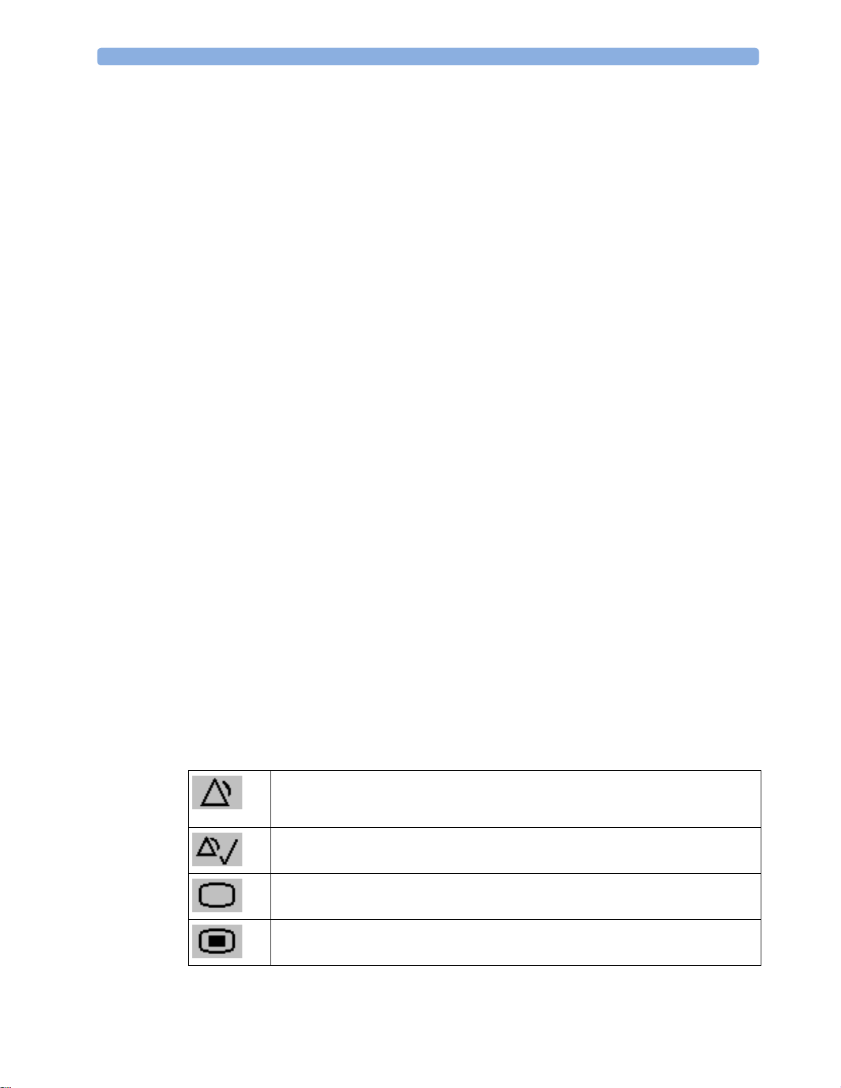
Pause Alarms - pauses alarm indicators. Pause duration depends on monitor
configuration. If pause duration is infinite, this key is labeled
Select again to immediately re-enable alarm indicators.
Silence - acknowledges all active alarms by switching off audible alarm indicators and
lamps.
Main Screen - close all open menus and windows and return to the main screen.
Main Setup - enter main setup menu.
Alarms Off.
Page 27
SmartKeys
1 Introduction
A SmartKey is a configurable graphical key, located at the bottom of the main screen. It gives you fast
access to functions. The selection of SmartKeys available on your monitor depends on your monitor
configuration and on the options purchased. If you have an integrated PC (iPC) you may also see
Smartkeys generated by applications on the iPC.
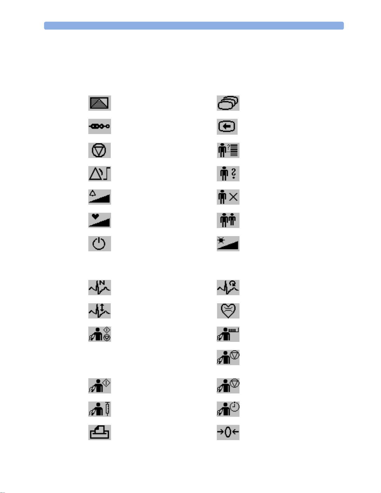
enter profile menu, or revert to
default profile
show BIS Sensor previous Screen
freeze waves quick admit a patient
set alarm limits enter patient identification menu to
change alarm volume end case to discharge a patient
change QRS volume view information for patients in
enter standby mode - suspends
patient monitoring. All waves and
numerics disappear from the display.
All settings and patient data
information are retained.
change Screen, or revert to default
screen
admit/discharge/transfer
other beds
change screen brightness (not for
independent displays)
review beat labels (annotate
arrhythmia wave)
change amplitude (size) of ECG
wave
- start/stop manual NBP
measurement
- start auto series
- stop current automatic
measurement within series
start NBP measurement and
measurement series
start veni puncture (inflate cuff to
subdiastolic pressure)
access patient reports zero invasive pressure transducer
re-learn arrhythmia
enter cardiac output procedure
start NBP STAT measurement
stop automatic or STAT NBP
measurement and measurement
series
stop current NBP measurement
set the NBP repeat time
27
Page 28
1Introduction
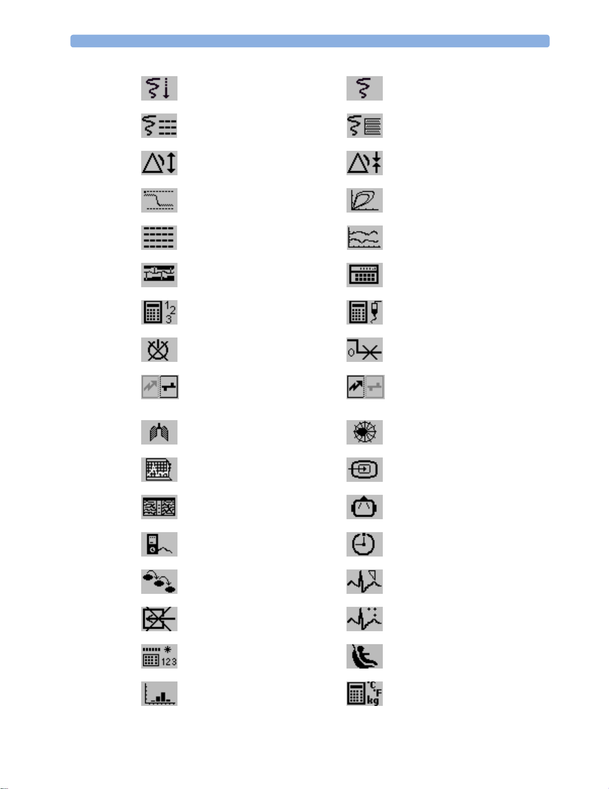
start a delayed recording access pop-up recording keys
access Vital Signs recording function access Select Waves recording
function
set wide automatic alarm limits set narrow automatic alarm limits
access wedge procedure window access the Loops window
review vital signs trend review graph trend
access event surveillance access calculations
access the calculator access the Drug Calculator
gas analyzer - exit standby mode suppress zero for all gas
measurements
unpair equipment and continue
central monitoring with the monitor
unpair equipment and continue
central monitoring with the telemetry
device
access the spirometry data window access ST Map application
start 12-Lead Capture (only available
if Information Center is connected)
access remote applications (if
Application Server is connected)
access EEG CSA access the EEG montage
display external device information access timers
access ProtocolWatch set standard or EASI lead placement
switch CO
pump off new lead setup
2
28
enter data manually start/stop car seat assessment record
open the
Histogram window open Unit Conversion window
Page 29

Hardkeys
A hardkey is a physical key on a monitoring device, such as the zero pressure key on the MMS or a
setup key on a module.
Pop-Up Keys
Pop-up keys are task-related graphical keys that appear automatically on the monitor screen when
required. For example, the
Confirm pop-up key appears only when you need to confirm a change.
Using the Remote Control
1 Introduction
The remote control provides you with direct access to five hard keys, a navigation knob and a numeric
keypad:
Hardkeys
1 Silence - acknowledges all active alarms by switching off audible alarm indicators and lamps.
Behavior follows the Silence permanent key configuration.
2 Alarms Off/Pause Alarms - pauses alarm indicators. Behavior follows the Pause Alarms
permanent key configuration.
3 Main Screen - close all open menus and windows and return to the main screen.
4 SmartKeys - display a block of SmartKeys specially configured for remote tasks (see below)
5 Back - go back one step to the previous menu.
29
Page 30

1Introduction
Keypad
6 Type numeric data on the keypad and press the Enter key to enter the data on the monitor.
Navigation knob
7 Rotate the knob to highlight screen elements, then press to select the highlighted element.
The remote control can be used with a USB cable connection to the monitor or without a cable using
short range radio. When used without a cable, the remote control must be assigned to the monitor.
The assignment is made in Configuration or Service mode.
CAUTION
When using a remote control without a cable, it is important that the user knows which remote control
is assigned to which monitor. Use the tethering cable delivered with the remote control to attach it to a
bed rail or IV pole, or label the remote control with the bed or monitor ID.
Using the SmartKeys Key
The SmartKeys hard key on the remote control displays a block of SmartKeys on the monitor screen.
Nine SmartKeys appear in a 3 by 3 matrix which corresponds to the layout of the numeric pad on the
remote control.
Pressing the 1 key on the remote control selects the top left SmartKey, pressing the 8 key selects the
bottom center SmartKey. The . and the key can be used to select the arrow keys to page up and
down in the available SmartKeys.
The SmartKeys which appear can be configured so that you have the functions available which you
most often need when using the remote control. If no list of SmartKeys has been configured, the
standard SmartKeys will be displayed and you can page through to the key you want.
Using the On-Screen Keyboard
30
Use this as you would a conventional keyboard. Enter the information by selecting one character after
another. Use the
single characters, or use the
entered and close the on-screen keyboard.
If a conventional keyboard is connected to the monitor, you can use this instead of or in combination
with the on-screen keyboard.
Shift and capital Lock keys to access uppercase letters. Use the Back key to delete
Clr key to delete entire entries. Select Enter to confirm what you have
Page 31

Using the On-Screen Calculator
You can use the on-screen calculator to perform any of the standard operations for which you would
normally use a handheld calculator.
1 Introduction
• To access the on-screen calculator, select the
Calculations followed by Calculator.
Operating Modes
When you switch the monitor on, it starts up in monitoring mode. To change to a different mode:
1 Select the Main Setup menu.
2 Select Operating Modes and choose the mode you require.
Your monitor has four operating modes. Some are passcode protected.
• Monitoring Mode: This is the normal, every day working mode that you use for monitoring
patients. You can change elements such as alarm limits, patient category and so forth. When you
discharge the patient, these elements return to their default values. Changes can be stored
permanently only in Configuration Mode. You may see items, such as some menu options or the
altitude setting, that are visible but ‘grayed out’ so that you can neither select nor change them.
These are for your information and can be changed only in Configuration Mode.
• Demonstration Mode: Passcode protected, this is for demonstration purposes only. You must
not change into Demonstration Mode during monitoring. In Demonstration Mode, all stored
trend information is deleted from the monitor’s memory.
• Configuration Mode: Passcode protected, this mode is for personnel trained in configuration
tasks. These tasks are described in the Configuration Guide. During installation the monitor is
configured for use in your environment. This configuration defines the default settings you work
with when you switch on, the number of waves you see and so forth.
Calculator SmartKey, or select Main Setup then
• Service Mode: Passcode protected, this is for trained service personnel.
When the monitor is in Demonstration Mode, Configuration Mode, or Service Mode, this is indicated
by a box with the mode name in the center of the Screen and a symbol in the bottom right-hand
corner. Select the mode box in the center of the screen to change to a different mode.
When an X2 or MP5 is connected to a host monitor (
• The monitor in companion mode will adopt the operating mode of the host monitor.
• You cannot change the operating mode at the monitor in companion mode.
Standby Mode
Standby mode can be used when you want to temporarily interrupt monitoring.
To enter Standby mode,
• select the
•select
The monitor enters Standby mode automatically after the End Case function is used to discharge a
patient.
Companion Mode is indicated):
Monitor Standby SmartKey or
Main Setup, followed by Monitor Standby.
31
Page 32

1Introduction
Standby suspends patient monitoring. All waves and numerics disappear from the display but all
settings and patient data information are retained. A special Standby screen is displayed. This can be
configured to a moving image or a blank screen. If a patient location is entered at the Information
Center, this will also be displayed on the Standby screen (availability depends on Information Center
revision).
To resume monitoring,
• Select anything on the screen or press any key.
If you connect an X2 or MP5 that is powered on (and not in Standby) to a host monitor in Standby
mode, the host will leave Standby mode. When connected to a host monitor, with both the host and
the monitor in companion mode in Standby mode, leaving Standby on the monitor in companion
mode will also make the host leave Standby.
Understanding Screens
Your monitor comes with a set of pre-configured Screens, optimized for common monitoring
scenarios such as OR adult, or ICU neonatal. A Screen defines the overall selection, size and position
of waves, numerics and other elements on the monitor screen when you switch on. You can easily
switch between different Screens during monitoring. Screens do NOT affect alarm settings, patient
category and so forth.
When you switch from a complex to a less complex Screen layout, some measurements may not be
visible but are still monitored in the background. If you switch to a more complex Screen with, for
example, four invasive pressure waves but you have only two pressures connected to the monitor, the
"missing" two pressures are either left blank or the available space is filled by another measurement.
Switching to a Different Screen
1 To switch to a different Screen, select the current Screen name in the monitor info line, or select
Change Screen SmartKey.
the
2 Choose the new Screen from the pop-up list.
Changing a Screen's Content
If you do not want to change the entire Screen content, but only some parts of it, you can substitute
individual waves, numerics, high-res waves, or trends. Be aware that these changes cannot be stored
permanently in Monitoring Mode.
To change the selection of elements on a Screen,
1 Select the element you want to change.
2 From the menu that appears, select Change Wave, Change Numeric, or ChangeHiResTrend, and
then select the wave or numeric you want, or select the high-resolution trend wave you want from
the list of available waves.
If you do not see
the numeric beside its wave. Changing the wave will automatically change the numeric.
Change Numeric in the menu, this Screen may be configured to always display
32
The changed Screen is shown with an asterisk in the monitor info line.
Change Screen menu, the changed Screen is shown linked to the original Screen and marked
In the
with an asterisk.
Page 33

Up to three modified Screens can be accessed via the Change Screen menu.
To recall Screens, either
1 Introduction
• select the name of the Screen in the
Change Screen menu
or
• use the previous/next arrows at the top of the
Change Screen menu to move back and forth in
the Screen history. The ten most recently-used Screens including up to three modified Screens can
be accessed.
After a patient discharge, the monitor's default Screen is shown. Modified Screens are still available in
Change Screen menu.
the
If the monitor is switched off and then on again, modified Screens are erased from the monitor's
memory and cannot be recalled. If a modified Screen was the last active Screen when the monitor was
switched off, it is retained (unless
Automat. Default is configured to Yes).
Connecting Additional Displays to the Monitor
You can connect a second display, showing the same Screen as the main display, to your monitor, for
viewing only.
If you have the optional independent display interface, you can connect a second display which can be
configured and operated individually using standard input devices.
For monitors with multiple displays and multiple input devices, the usage and behavior can be
configured according to specific requirements at installation (for example, use for two independent
operators or tracking of mouse input across two displays). For details refer to the Service Guide.
When two operators are using two displays, the scope of an action depends on the type of operation:
• Patient monitoring operations such as Silence or Pause alarms take effect for the monitor as a
whole, the results will be seen on both displays.
• Display operations such as the
Main Screen key and Back hardkey will take effect only on the
display being operated.
If you are operating two displays with one remote control, to navigate from one display to another:
1 Move the highlight to the Main Screen key and then turn one click further.
The highlighting moves to a special "jump" field at the edge of the Screen.
2 Press the navigation knob on the remote control to confirm; the highlighting will automatically
move to the other display.
The content of each Screen can be changed individually as described in the previous section. If you are
operating two displays, you can choose Screens for both displays from one location:
1 Select Profiles in the monitor info line of the first display,
2 Select Display 1, or Display 2, then select the Screen you want to appear on that display from the
list of available Screens.
When two displays are mounted next to each other or one above the other, a special Screen can be
assigned which spans across both displays. The Screen content for these Tall and Wide Screens can
then use the increased area available with two displays. These Screens appear in the Screen list with a
special Tall Screen or Wide Screen symbol.
33
Page 34

1Introduction
Certain windows (for example: cardiac output procedure) can only be shown on one display at a time.
If you try to open one of these windows when it is already shown on another display, you will see a
blank gray window with a cross through it.
Using the XDS Remote Display
Using the IntelliVue XDS solution it is possible to view an independent monitor screen on an external
display. The XDS solution consists of a medical grade PC-based hardware platform, XDS application
software and the XDS connectivity option on the monitor. Depending on the configuration you can
also operate the monitor from the external display. The XDS must be connected to the same Local
Area Network (LAN) as the monitor.
It is also possible to use an existing PC, connected to the same LAN, to host the XDS Application
software.
For more details, including limitations and restrictions, refer to the Instructions for Use for the XDS
Application.
Using the Visitor Screen
If a visitor Screen is configured for your monitor, you can use it to clear the screen of all waves and
numerics but continue to monitor the patient with active alarms and trend storage at the bedside and
Information Center. You can change the name of the visitor Screen in Configuration Mode.
• To activate this Screen, select the Screen name in the monitor info line to open the
menu, then select the name of the visitor Screen configured for your monitor from the list of
available Screens.
To select a Screen with waves and numerics again,
• Touch the gray box in the center of the screen, showing the visitor Screen's name, to open the
Change Screen menu and select a different Screen to show waves and numerics again.
Understanding Profiles
Profiles are predefined monitor configurations. They let you change the configuration of the whole
monitor so you can adapt it to different monitoring situations. The changes that occur when you
change a complete profile are more far reaching than those made when you change a Screen. Screens
affect only what is shown on the display. Profiles affect all monitor and measurement settings.
The settings that are defined by Profiles are grouped into three categories. Each category offers a
choice of 'settings blocks' customized for specific monitoring situations. These categories are:
• Display (screens)
Each profile can have a choice of many different predefined screens.
If you are using a second display, each display can have its own individual screen selection.
When you change the profile, the screen selection configured for the new profile becomes active.
• Measurement Settings
Each profile can have a choice of different predefined measurement settings. These relate directly
to individual measurements, for example, measurement on/off, measurement color, alarms limits,
NBP alarm source, NBP repeat time, temperature unit (°F or °C), pressure unit (mmHg or kPa).
Change Screen
34
Page 35
1 Introduction
• Monitor Settings
Each profile can have a choice of different predefined monitor settings. These relate to the
monitor as a whole; for example, display brightness, alarms off/paused, alarm volume, QRS tone
volume, tone modulation, prompt tone volume, wave speed, resp wave speed, pulse source.
You can change from one complete profile to another or swap individual settings blocks (display/
monitor settings/measurement settings) to change a subset of a profile. Changes you make to any
element within the settings blocks are not saved when you discharge the patient, unless you save them
in Configuration Mode.
Depending on your monitor configuration, when you switch on or discharge a patient the monitor
either continues with the previous profile, or resets to the default profile configured for that monitor.
WARNING
If you switch to a different profile, the patient category and paced status normally change to the setting
specified in the new profile. However some profiles may be set up to leave the patient category and
paced status unchanged. Always check the patient category, paced status, and all alarms and settings,
when you change profiles.
When you leave Demonstration Mode, the monitor uses the default profile.
Swapping a Complete Profile
1 Select Profiles in the monitor info line, or select the Profiles SmartKey.
2 In the Profiles menu, select Profile.
3 Chose a profile from the pop-up list.
4 Confirm your selection.
Swapping a Settings Block
1 Select Profiles in the monitor info line, or select the Profiles SmartKey.
2 In the Profiles menu, select Display or Measmnt.Settings or Monitor Settings to call up a list of
the settings blocks in each category.
3 Choose a settings block from the pop-up list.
4 Confirm your selection.
Default Profile
Your monitor has a default profile that it uses when you leave Demonstration, or Service modes, or
when you discharge a patient. This profile is indicated by a diamond shaped symbol.
35
Page 36

1Introduction
Locked Profiles
Some profiles are locked, so that you cannot change them, even in Configuration Mode.
These are indicated by this lock symbol.
Understanding Settings
Each aspect of how the monitor works and looks is defined by a setting. There are a number of
different categories of settings, including,
Screen Settings, to define the selection and appearance of elements on each individual Screen
Measurement settings, to define settings unique to each measurement, for example, high and low
alarm limits
Monitor settings, including settings that affect more than one measurement or Screen and define
general aspects of how the monitor works, for example, alarm volume, reports and recordings, and
display brightness.
You must be aware that, although many settings can be changed in Monitoring Mode, permanent
changes to settings can only be done in the monitor's Configuration Mode. All settings are reset to the
stored defaults:
• when you discharge a patient
• when you load a Profile
• when the monitor is switched off for more than one minute (if
Changing Measurement Settings
Each measurement has a setup menu in which you can adjust all of its settings. You can enter a setup
menu:
• via the measurement numeric - select the measurement numeric to enter its setup menu. For
example, to enter the
• via the Setup hardkey (on plug-in modules) - press the Setup hardkey on the module front.
•via the
• via the Measurement Selection key.
This guide always describes the entry method using the setup menu. But you can use any method you
prefer.
Main Setup permanent key - if you want to setup a measurement when the measurement is
switched off, use the
measurement name from the pop-up list. With this permanent key you can access any setup menu
in the monitor.
Setup ECG menu, select the HR (heart rate) numeric.
Main Setup permanent key and select Measurements. Then select the
Automat. Default is set to Yes).
36
Page 37

Switching a Measurement On and Off
When a measurement is off, its waves and numerics are removed from the monitor's screen. The
monitor stops data acquisition and alarming for this measurement. A measurement automatically
switches off if you disconnect its module or MMS. If you disconnect a transducer, the monitor
replaces the measurement numeric with question marks. If in this situation alarms are paused or
switched off, the measurement in question may be switched off completely, depending on monitor
configuration.
1 Enter the measurement's setup menu and select the measurement.
2 Select the measurement name to switch between on and off. The screen display indicates the active
setting.
Switching Numerics On and Off
For some measurements, such as EEG, you can choose which numerics to view on the screen.
In the measurement's setup menu, select the numeric name to toggle between on and off.
1 Introduction
For example in the
Setup EEG menu, select the EEG numeric name to toggle between on and off.
Adjusting a Measurement Wave
To quickly adjust wave-related measurement settings (such as speed or size), select the measurement
wave itself. This displays the measurement wave menu, which has only wave-related measurement
settings.
Changing Wave Speeds
Lowering the wave speed compresses the wave and lets you view a longer time period. Increasing the
speed expands the waveform, giving you a more detailed view.
The monitor distinguishes three groups of wave speed settings,
RespiratorySpeed, for all respiratory waves: CO
•
• EEG Speed, for all EEG and BIS waves
Global Speed, for all waves not included in the other two groups.
•
Changing the Wave Group Speed
The wave speed group setting defines the speed of all the waves in the group.
To change the wave speed of a wave speed group,
, anesthetic agents and O
2
2
1 Select Main Setup, then select User Interface
2 Select Global Speed, RespiratorySpeed, or EEG Speed as required
3 Select a value from the list of available speeds.
Changing Wave Speed for a Channel
To change the wave speed of an individual wave channel,
1 Enter the Wave menu for a measurement by selecting its wave.
2 Select Change Speed.
37
Page 38

1Introduction
To set the speed to the wave group speed, select RespiratorySpeed, EEG Speed, or Global Speed.
3
To set an individual channel speed, select a numeric value from the list of available speeds. This
overrides the wave group speed setting and set the speed for the individual wave channel on the
monitor Screen. The wave channel speed is independent of the wave (label) depicted in the
channel, if you change the wave, the new wave will retain the set channel speed.
Freezing Waves
You can freeze waves on the screen and measure parts of the wave using cursors. The waves are frozen
with a history of 20 seconds so that you can go back and measure what you have seen.
Freezing An Individual Wave
To freeze a wave,
1 Enter the Wave menu for the measurement by selecting the wave on the screen.
2 Select Freeze Wave.
The realtime wave is replaced with the frozen wave.
Freezing All Waves
To freeze all waves on the screen,
1 Select the Freeze Waves SmartKey.
All realtime waves are replaced with frozen waves.
Measuring Frozen Waves
To measure a frozen wave,
1 Select the frozen wave.
If you are using touch, this automatically positions the vertical cursor. The cursor can be
repositioned by touching the required point on the wave, or
2 Using the SpeedPoint or another pointing device or touch: use the right/left arrow keys to move
the vertical cursor.
The vertical cursor moves through the time axis and the current value is displayed next to the
cursor.
3 Use the up/down arrow keys to activate and move the horizontal cursor.
The horizontal cursor measures the wave value, which is displayed above the cursor line. If the
wave is a pressure wave, the cursor value can be stored as a systolic, diastolic or mean pressure
value; if the pressure wave is a PAP wave it can also be stored as a PAWP value; for pressure waves
P, P1 to P8 it can also be stored as an IAP value. The stored value appears in the trend database as
a manually entered value.
Changing The Wave Speed
Lowering the wave speed compresses the wave and lets you view a longer time period. Increasing the
speed expands the waveform, giving you a more detailed view.
38
Page 39

To change the wave speed:
1 Select the frozen wave.
2 Select Change Speed.
3 Select a speed from the list.
Updating The Frozen Wave
To update the wave, that is freeze the current wave:
1 Select the frozen wave.
2 Select Freeze Again.
Releasing Frozen Waves
To release frozen waves,
1 Select a frozen wave.
2 Select Unfreeze Waves.
All frozen waves are released.
1 Introduction
Using Labels
You may have more than one instance of some measurements, for example pressure, being used
simultaneously. The monitor uses labels to distinguish between them. The default settings defined in
the profile (such as measurement color, wave scale, and alarm settings) are stored within each label.
When you assign a label to a measurement, the monitor automatically applies these default settings to
the measurement. The labels assigned are used throughout the monitor, in reports, recordings, and in
trends.
Changing Measurement Labels (e.g. Pressure)
To change a measurement label of a measurement with multiple labels (e.g. invasive pressure or
temperature),
1 Enter the wave menu of the measurement.
2 Select Label.
3 Choose a label from the list.
The monitor automatically applies the scale, color, etc. settings stored in the Profile for the label you
select. You can change scale settings in Monitoring Mode, but color can only be changed in the
monitor's Configuration Mode.
Any labels already being used in the monitor are shown "grayed-out" in the list and cannot be selected.
About Label Sets
Your monitor may be configured to use a Restricted or Full label set. The Full label set provides extra
labels for Pressure and Temp. See the sections on Pressure and Temperature in these Instructions for
Use for more information.
If you connect an MMS from a monitor using a
Restricted label set or an M3/M4 monitor, any additional labels switch to labels available in the target
monitor. This may cause a label conflict with other monitored measurements.
Full label set to an IntelliVue monitor using a
39
Page 40

1Introduction
Be aware that connecting a monitor using the Full label set to an Information Center with certain
software revisions may affect the availability of measurement information from the additional labels on
the Information Center. See the Information Center documentation and your monitor's Configuration
Guide for information on label set compatibility.
Resolving Label Conflicts
Each label must be unique, that is, it can only be assigned once. You cannot monitor two pressures
labeled "ICP" at the same time. If you need to use two identical pressures, you must assign different
labels to them, for example, P and ICP.
Measurement labels are stored in the measurement device (module or MMS). If you try to use two
measurement devices that have identical labels, this causes a label conflict in the monitor.
Measurement selection key with question marks indicating a label conflict.
Depending on your configuration, the monitor will either
• resolve the conflict automatically, by assigning a new, generic label to the most recently connected
conflicting label (e.g. a second FAP label could be changed to ABP)
•display the
• take no action, you must enter the
Measurement Selection window automatically for you to resolve the conflict
Measurement Selection window and resolve the conflict.
All the currently available measurement devices, for example MMSs, MMS extensions, measurement
modules, Gas analyzers, devices connected to a host monitor and manually entered measurements
(marked ), are depicted in the
Measurement Selection window.
De-activated devices are grayed-out (here
the Temp measurement on the left)
Any measurement labels causing a label conflict are shown in red. If a measurement device is
connected but currently unavailable, for example, because it was deactivated due to a label conflict, the
device is shown "grayed-out".
40
Page 41

1 Introduction
When an X2 or MP5 is connected to a host monitor, the measurement selection window looks like
this:
X2 connected to host monitor MP5 connected to host monitor
WARNING
When an X2 or MP5 with an active measurement, say SpO2, is connected to a host monitor with the
same measurement already active, the SpO
Meas. DEACTIVATED INOP is displayed. The measurement can only be reactivated if the X2 or MP5
measurement on the X2 or MP5 is deactivated and the
2
is disconnected from the host monitor. The label conflict can be resolved on the host monitor like any
other label conflict.
To resolve a label conflict:
1 Select the measurement selection key or select Main Setup, then Meas. Selection to display the
Measurement Selection window.
2 Select the device whose label you want to correct.
3 Use the measurement selection pop-up keys to resolve the conflict. Select either:
Change Label: to assign a different label to the conflicting label
–
–
De- Activate: to disable the conflicting device. It retains its label for future use but becomes
invisible to the monitor, as though it had been unplugged. When the device has been
deactivated the question marks under the measurement selection key will be replaced by XXX.
Setup <Measurement Label>: to enter the Setup menu for the measurement and change the
–
conflicting device's label to a different label.
Modify Driver (VueLink/IntelliBridge only): - to modify the device driver setup to disable the
–
conflicting device's label.
Label Compatibility
When a new measurement is introduced, or new labels for an existing measurement, these labels will
not be shown on older Information Centers, and consequently not on the Overview screen sourced
from the Information Center.
When a patient is transferred from a monitor with these new labels to one with an older software
revision, the labels will be replaced with a generic label for that measurement. The settings for that
generic label will then be used.
41
Page 42

1Introduction
If it is critical that the measurement labels are available at the Information Center and after transfers,
the older monitors and the Information Center must be upgraded to the appropriate software revision.
Entering Measurements Manually
You can enter values into the monitor that have been measured with other equipment or manually (for
example, manual temperatures, lab values). These values are then stored in the database, included in
trends and reports, and passed on to the Information Center and central charting systems. There is no
alarm functionality for manually entered measurements.
To enter values,
1 Select the Enter Values SmartKey or select Main Setup then select Enter MeasValues.
2 Select the measurement you want to enter values for. The Edit window will open.
3 If the measurement is switched off, switch it on by selecting the label.
4 Select Value and enter the value.
5 Select Date/Time to enter the date and time for the value. The default is always the current date
and time.
6 For compound labels, for example ABPs, ABPd and ABPm, select the Format field to select
whether all values are required or a single value.
7 Select Save.
When a manually entered value has been configured to display as a numeric on the screen, you can also
enter a new value for this measurement by selecting the numeric, then selecting
Manually entered measurement values are marked with a * on the display, in trends, and so forth. Each
measurement has a defined measurement interval after which a value becomes invalid (no value is then
displayed). Values can be entered up to two hours after they have been measured or up to the
measurement interval, if this is shorter.
The list of measurement labels which appears in the
Configuration Mode.
No values can be entered manually on a monitor in companion mode when it is connected to a host
monitor.
Enter Measurement Values window is set in
Switching Manually Entered Measurements On and Off
To switch a manually entered measurement on or off,
1 Select the Enter Values SmartKey or select Main Setup then select Enter MeasValues.
2 Select the measurement you want to switch on or off.
3 Select the measurement label field to switch between On and Off.
Changing Monitor Settings
Enter MeasValues.
42
To change monitor settings such as brightness, or QRS tone volume, select the Main Setup permanent
key and then select
User Interface to enter a submenu where you can change these settings.
Page 43

Adjusting the Screen Brightness
1 Select the Brightness SmartKey.
2 Select the appropriate setting for the screen brightness. 10 is the brightest, 1 is the least bright.
Optimum is suitable for most monitoring locations and optimizes power usage for battery
powered monitors.
Your monitor may be configured with a lower brightness for Standby mode and also (for battery
powered monitors) for transport to conserve battery power. These settings can only be changed in the
monitor's Configuration Mode.
1 Introduction
If you are using a monitor with an external display, the
brightness of this display. See the instructions supplied with the external display for instructions.
Brightness SmartKey does not adjust the
Setting the Date and Time
1 Select the Date, Time screen element from the monitor's info line to enter the Date, Time menu.
2 Select, in turn, the Year, Month, Day, Hour (in 24 hour format, only) and Minute as necessary.
Select the correct values from the pop-up list.
3 Select Store Date, Time to change the date and time.
If your monitor is connected to an Information Center, the date and time are automatically taken from
this. Once it is set, the internal clock retains the setting even when you switch off the monitor.
WARNING
Changing the date or time will affect the storage of trends and events.
Checking Your Monitor Revision
1 Select Main Setup then select Revisions to open the Monitor Revision menu.
2 Select the correct device from the device pop-up keys.
3 From the Monitor Revision menu, select the monitor component for which you need revision
information.
Getting Started
Once you understand the basic operation principles, you can get ready for monitoring. We also
recommend working through the CBT for self-training before using the monitor (not available in all
languages).
43
Page 44

1Introduction
Inspecting the Monitor
WARNING
If the monitor is mechanically damaged, or if it is not working properly, do not use it for any
monitoring procedure on a patient. Contact your service personnel.
1 Before you start to make measurements, carry out the following checks on the monitor including
all connected MMSs, modules, or MMS extensions.
– Check for any mechanical damage.
– Check all the external cables, plug-ins and accessories.
2 Plug the power cord into the AC power source.
3 Check all the functions of the instrument that you need to monitor the patient, and ensure that the
instrument is in good working order.
Switching On
Press the power on/standby switch on the monitor for one second. The monitor performs a self test
during which all lamps will light up and a tone will be sounded, and is then ready to use. If you see a
message such as
measurement. Connected devices usually take their power from the monitor. External devices such as
gas monitors and those connected via VueLink/IntelliBridge have their own power switches.
CO₂ SENS.WARMUP wait until it disappears before starting to monitor that
Power On/Power Off Behavior
The general rules determining the behavior of the monitor when connected to, or disconnected from
power are as follows:
• A monitor that was switched on prior to a temporary power loss switches on again when power is
restored.
• A monitor that was switched off prior to a temporary power loss remains off when power is
restored.
• An X2 or MP5 switches on automatically when connected to a running host monitor.
• When an X2 or MP5 is disconnected from a running host monitor, the X2 or MP5 continues to
run without interruption on battery power.
Setting up the Modules
1 Decide which measurements you want to make.
2 Connect the required modules, MMSs, or MMS extensions.
3 Check that you have the correct patient cables and transducers plugged in. The connectors are
color-coded to the patient cables and transducers for easy identification.
Starting Monitoring
After you switch on the monitor,
44
1 Admit your patient to the monitor.
2 Check that the profile, alarm limits, alarm and QRS volumes, patient category and paced status and
so forth are appropriate for your patient. Change them if necessary.
Page 45

Refer to the appropriate measurement chapter for further details of how to perform the
3
measurements you require.
WARNING
During MR imaging, remove all transducers, sensors and cables from the patient. Induced currents
could cause burns.
Disconnecting from Power
The On/Standby switch does not disconnect the monitor from the ac power source. To disconnect,
unplug the power cable.
Monitoring After a Power Failure
If the monitor is without power for less than one minute, monitoring will resume with all active
settings unchanged. If the monitor is without power for more than one minute, the behavior depends
on your configuration. If
is restored. If
48 hours. The
Automat. Default is set to No, all active settings are retained, if power is restored within
Automat. Default setting is made in Configuration Mode.
Automat. Default is set to Yes, the default profile will be loaded when power
1 Introduction
Networked Monitoring
You can connect your monitor to an Information Center on a network, using one of the optional
interfaces:
• Standard wired LAN
• Wireless LAN
• IntelliVue Instrument Telemetry System (IIT).
WARNING
Do not connect patient monitors to the standard hospital network.
Additionally, when an IntelliVue X2 or MP5 is equipped with IIT and declared at the Information
Center as a telemetry device, it allows data continuity when paired to a host monitor. After
disconnection from the host monitor, it continues to monitor the patient during transport and
provides continuous data to the same sector on the Information Center. (See “Assigning a Telemetry
Device and a Monitor to One Patient” on page 265.)
If your monitor is connected to a network, a network symbol is displayed in the upper left corner next
to the bed label. To see details about the Care Group, the monitoring equipment, and technical
information about the network,
• in the monitor info line, select the bed label.
Be aware that some network-based functions may be limited for monitors on wireless networks in
comparison to those on wired networks.
Printout functionality and data export are not guaranteed when using a standard hospital network.
45
Page 46

1Introduction
Using the Integrated PC
If your monitor has the optional integrated PC (iPC), you can run applications on the iPC. The
applications display data on the monitor's display (or on a second independent display) that is
generated on and retrieved from the iPC or externally.
For details about applications, refer to the XDS/iPC Instructions for Use.
The monitor runs independently of the iPC, and vice versa.
WARNING
• Some clinical applications may show data from another patient. Be aware that some of the data on
your patient monitor display may not always be from your patient.
• Applications running on the iPC cannot act as a primary alarming device and cannot be relied
upon for alarm notification. There may be no audible or visible indications apart from what is
shown on the screen and any data shown may be delayed.
Starting the iPC
Your monitor may be configured to have the iPC start up automatically when the monitor is switched
on. If not:
1 Select Main Setup then Internal PC.
2 In the Internal PC menu, select Switch PC On to start the iPC.
Viewing the iPC Desktop on the Monitor Display
If the Desktop is not displayed on the monitor display:
1 Select the iPC key , or
2 Select Main Setup, Internal PC, then Show PC Window.
To hide the Desktop again, select
Main Screen.
Adjusting the iPC Audio Volume
The Audio from the iPC is normally configured to be off. However, your monitor may have the iPC
audio configured on for use with specific PC applications.
WARNING
Always minimize the iPC audio volume or mute it completely when it is not needed for an iPC
application. This will avoid iPC tones distracting from or masking tones from the monitor.
46
Page 47

Using Input Devices with the iPC and Monitor
You can connect input devices such as a mouse, trackball and keyboard to the rear of the patient
monitor (using the left hand row of USB connectors) and use them for input to the monitor.
Correspondingly you can connect input devices to the rear of the patient monitor (using the right
hand row of USB connectors) or to the front USB connector and use them for the iPC. Input devices
connected to the iPC can also be shared with the patient monitor. Sharing input devices and
touchscreen input requires a specific software application; refer to the IntelliVue XDS Application
Instructions for Use for details.
If the iPC is switched off when input devices are shared, any input devices connected to it will not be
available for use with the monitor.
Shutting the iPC Down
The iPC will be shut down automatically when the monitor is switched off.
If you want to shut down the iPC when the monitor is on,
1 Select Main Setup then Internal PC.
2 In the Internal PC menu, select Switch PC Off.
If there is a problem with the shutdown, and you need to switch off the iPC manually,
1 Introduction
1 Select Main Setup then Internal PC.
2 In the Internal PC menu, select Force PC Off to force the iPC to power down.
Special Situations at Shutdown
• If you switch the monitor off and then on again immediately, the iPC will continue running and
will not be shut down.
• In some situations, shutting down the iPC can take a little time. The monitor will go into Standby
mode until the shutdown is complete. By touching the touchscreen, you can bring the monitor
back into operating mode. If you do this, the iPC will restart when the shutdown is complete.
• If the shutdown cannot be completed within a certain time, a window will open giving the reason:
for example, that a file has not been saved, or that updates are being installed. You can then decide
whether to wait (for example, in the case of the updates) or to take action (for example by saving
the unsaved file). You will also have the option to force shutdown, if necessary.
Using the X2 or MP5 with a Host Monitor
When you connect an X2 or MP5 in companion mode to a host monitor, an integrated system is
formed for monitoring a single patient. The following general observations and considerations apply to
such a system:
• The host monitor is the "master" of the system, and you have full control over all the system's
operation only via the host monitor.
• Functions you can operate on a monitor in companion mode are restricted to measurements
originating in that device. If you try to operate controls that are disabled, you are prompted by the
message
Not available in Companion Mode.
47
Page 48

1Introduction
• Depending on how it is configured, your host monitor can determine whether the user interface of
• Global settings such as line frequency, QRS sound and ECG lead colors from the host monitor,
• No audible alarms are available on a monitor in companion mode when connected to a host
• The host monitor is the master of all ADT information. ADT operations on the monitor in
• The date and time of the monitor in companion mode is synchronized with that of the host
• Event surveillance in the monitor in companion mode is disabled. Main Setup menu operations
a connected monitor in companion mode is completely disabled or not, and what is displayed on
the screen (a standard main screen, or a blank screen indicating
Companion Mode).
This is controlled by two monitor settings that are applied to the monitor in companion mode on
connection. You can change the settings in Configuration Mode.
are applied to the monitor in companion mode on connection. When disconnected from the host,
the monitor in companion mode re-applies its own global settings.
monitor. The only visual alarm indication is provided by the alarm lamps which are controlled by
the host monitor. Alarms become active again as soon as the monitor in companion mode is
disconnected from the host monitor.
companion mode are disabled, and any pending actions on the monitor in companion mode (for
example, admit or end case) are canceled.
monitor.
and SmartKeys are disabled. While connected to a host monitor, no new events are detected in the
monitor in companion mode, and no events are deleted. There is no transfer of stored events from
the monitor in companion mode to the host monitor. After disconnection from the host monitor,
event surveillance is enabled again in the monitor in companion mode, and new events are
detected.
48
Page 49

2
2Alarms
The alarm information here applies to all measurements. Measurement-specific alarm information is
discussed in the sections on individual measurements.
The monitor has two different types of alarm: patient alarms and INOPs.
Patient Alarms
Patient Alarms are red and yellow alarms. A red alarm indicates a high priority patient alarm such as a
potentially life threatening situation (for example, asystole). A yellow alarm indicates a lower priority
patient alarm (for example, a respiration alarm limit violation). Additionally there are short yellow
alarms, most of which are specific to arrhythmia-related patient conditions (for example, ventricular
bigeminy).
INOPs
INOPs are technical alarms, they indicate that the monitor cannot measure or detect alarm conditions
reliably. If an INOP interrupts monitoring and alarm detection (for example,
places a question mark in place of the measurement numeric and an audible indicator tone will be
sounded. INOPs without this audible indicator indicate that there may be a problem with the reliability
of the data, but that monitoring is not interrupted.
LEADS OFF), the monitor
Most INOPs are light blue, however there are a small number of INOPs which are always yellow or
red to indicate a severity corresponding to red and yellow alarms. The following INOPs can also be
configured as red or yellow INOPs to provide a severity indication:
ECG LEADS OFF
•
• NBP CUFF OVERPRESS
• CUFF NOT DEFLATED
• OCCLUSION
• TELE DISCONNECTED
• Replace TeleBatt
All monitors in a unit should have the same severity configured for these INOPs.
Alarms are indicated after the alarm delay time. This is made up of the system delay time plus the
trigger delay time for the individual measurement. See the Specifications section for details.
If more than one alarm is active, the alarm messages are shown in the alarm status area in succession.
An arrow symbol next to the alarm message informs you that more than one message is active.
49
Page 50

2 Alarms
The monitor sounds an audible indicator for the highest priority alarm. If more than one alarm
condition is active in the same measurement, the monitor announces the most severe. Your monitor
may be configured to increase alarm indicator volume automatically during the time when the alarm is
not acknowledged.
Visual Alarm Indicators
WARNING
• No alarms are available on an X2 or MP5 when connected to a host monitor (Companion Mode
is indicated). Alarms become active again as soon as the X2 or MP5 is disconnected from the host
monitor.
• Alarm fields and other visual alarm indicators are disabled on an X2 or MP5 when connected to a
host monitor. The only visual alarm indication is provided by the alarm lamps, which are
controlled by the host monitor.
Alarm Message
An alarm message text appears in the alarm status area at the top of the screen indicating the source of
the alarm. If more than one measurement is in an alarm condition, the message changes every two
seconds, and has an arrow ( ) at the side. The background color of the alarm message matches the
alarm priority: red for red alarms, yellow for yellow alarms, light blue for standard INOPs, red for red
INOPs and yellow for yellow INOPs. The asterisk symbols (
alarm priority:
not have a symbol, red and yellow INOPs have exclamation marks beside the alarm message:
red INOPs and
Depending on how your monitor is configured, it may display alarm limit violation messages:
• in text form, for example
• in numeric form, for example
deviation from the alarm limit, and the second number shows the currently set limit.
*** for red alarms, ** for yellow alarms, * for short yellow alarms. Standard INOPs do
Flashing Numeric
The numeric of the measurement in alarm flashes.
Bright Alarm Limits
If the alarm was triggered by an alarm limit violation, the corresponding alarm limit on the monitor
screen is shown more brightly if
screen.
Alarm Lamp
A lamp on the monitor's front panel flashes. The alarm lamp is divided into two sections. The right
one flashes for a patient alarm, except for short yellow alarms where the lamp will light for
approximately six seconds. The color is yellow or red corresponding to the highest priority patient
alarm currently present. The left one lights continuously for a light blue INOP and flashes for yellow
or red INOPs as follows:
*) beside the alarm message match the
!!! for
!! for yellow INOPs.
** SpO₂ LOW or
**Pulse xxx>yyy where the first number shows the maximum
Show ALarmLimits is enabled and there is sufficient room on the
50
Page 51

INOP Lamp Color On Off
Yellow 1.0 seconds 1.0 seconds
Red 0.25 seconds 0.25 seconds
If only patient alarms are present, and no INOPs, the patient alarms will use both left and right
sections to flash (for red and yellow alarms) or light for approximately six seconds (for short yellow
alarms). If only INOPs are present, and no patient alarms, red and yellow INOPs will use both left and
right sections to flash but light blue INOPs will always light continuously in the left section only.
Nurse Call Systems
If configured to do so, red, yellow and light blue alarms are indicated on any device connected to the
nurse call relay.
Audible Alarm Indicators
The audible alarm indicators configured for your monitor depend on which alarm standard applies in
your hospital. Audible alarm indicator patterns are repeated until you acknowledge the alarm by
switching it off or pausing it, or until the alarm condition ceases (if audible alarm indication is set to
non-latching).
2 Alarms
WARNING
• Do not rely exclusively on the audible alarm system for patient monitoring. Adjustment of alarm
volume to a low level or off during patient monitoring may result in patient danger. Remember
that the most reliable method of patient monitoring combines close personal surveillance with
correct operation of monitoring equipment.
• No audible alarm indicators are available on an X2 or MP5 when connected to a host monitor
Companion Mode is indicated). Alarms become active again as soon as the X2 or MP5 is
(
disconnected from the host monitor.
Alarm Tone Configuration
The audible alarm indicators of your monitor are configurable. In the monitor's Configuration Mode,
you can:
• increase the alarm volume of unacknowledged alarms at regular intervals
• change the interval between alarm sounds (ISO/IEC Standard alarms only)
• change the base volume of the red and yellow alarm tones and the INOP tones
• change the alarm sound to suit the different alarm standards valid in different countries.
Traditional Audible Alarms (HP/Agilent/Philips/Carenet)
• Red alarms and red INOPs: A high pitched sound is repeated once a second.
• Two-star yellow alarms and yellow INOPs: A lower pitched sound is repeated every two seconds.
• One-star yellow alarms (short yellow alarms): The audible indicator is the same as for yellow
alarms, but of shorter duration.
51
Page 52

2 Alarms
• Standard INOPs: an INOP tone is repeated every two seconds.
ISO/IEC Standard Audible Alarms
• Red alarms and red INOPs: A high pitched tone is repeated five times, followed by a configurable
pause.
• Two-star yellow alarms and yellow INOPs: A lower pitched tone is repeated three times, followed
by a configurable pause.
• One-star yellow alarms (short yellow alarms): The audible indicator is the same as for yellow
alarms, but of shorter duration.
• Standard INOPs: a lower pitched tone is repeated twice, followed by a pause.
Changing the Alarm Tone Volume
• The alarm volume symbol at the top right of the monitor screen gives you an indication of the
current volume.
To change the volume, select the volume symbol and then select the required volume from the
pop-up selection.
• If you want to see a numerical indication of the current alarm volume on a scale from zero to 10,
or change the setting, select the
The volume scale pops up. The current setting is indented. To change the setting, select the
required number on the scale. Any settings that are inactive ("grayed out") have been disabled in
the monitor's Configuration Mode.
• When the alarm volume is set to zero (off), the alarm volume symbol reflects this.
If you switch the alarm volume off, you will not get any audible indication of alarm conditions.
There is no alarm volume indication on the screen of an X2 or MP5 when connected to a host monitor
Companion Mode is indicated).
(
Alarm Volume SmartKey.
Minimum Volume for No Central Monitoring INOP
If your monitor is connected to an Information Center, and the connection is interrupted, the INOP
message
ensure that this INOP, and any other active alarm, is not overlooked, the INOP and alarm tones may
be configured to have a minimum volume. In this case, INOP and alarm tones will sound even if the
monitor alarm volume is set to zero.
No Central Monit. will appear within 30 seconds, accompanied by an INOP tone. To help
Minimum Volume for Severe Yellow or Red INOPs
Severe yellow or red INOPs require action to ensure the well-being of the patient. Therefore the
minimum volume for the INOP tone is set to at least alarm volume 8, irrespective of the current alarm
volume setting. The INOP tone will sound even if the monitor alarm volume is set to zero.
52
Page 53
The severe INOPs for which this applies are:
CUFF NOT DEFLATED (configurable to yellow or red)
NBP CUFF OVERPRESS (configurable to yellow or red)
!!INSERT BATTERY - X2 (yellow)
Power Loss Tone
When power is lost - no power is available via the power cable - a buzzer will sound, if so configured.
The tone can be silenced by pressing the On/Off power switch.
Acknowledging Alarms
To acknowledge all active alarms and INOPs, select the Silence permanent key. This switches off the
audible alarm indicators and alarm lamps.
2 Alarms
Alternatively, you can acknowledge alarms by pressing the
SpeedPoint. The hardkeys follow the behavior configured for the permanent key.
A check mark beside the alarm message indicates that the alarm has been acknowledged . If the
monitor is configured to re-alarm, a dashed check mark will be shown .
If the condition that triggered the alarm is still present after the alarm has been acknowledged, the
alarm message stays on the screen with a check mark symbol beside it, except for NBP alarms and
alarms from other intermittent measurements. When such an alarm is acknowledged the alarm
message disappears.
If the alarm condition is no longer present, all alarm indicators stop and the alarm is reset.
Switching off the alarms for the measurement in alarm, or switching off the measurement itself, also
stops alarm indication.
Acknowledging Disconnect INOPs
Acknowledging an INOP that results from a disconnected transducer switches off the associated
measurement, unless the monitor is configured to not allow this. The only exception is ECG/Resp:
acknowledging a disconnect INOP for ECG leads does not switch off the ECG and Resp
measurements. Acknowledging a disconnect INOP at the Information Center switches off the audible
INOP indicator but does not switch off the measurement.
Silence hardkey on the MMS or on the
Unplugging an MMS or a plug-in module automatically switches off its measurements.
53
Page 54

2 Alarms
Alarm Reminder
If Alarm Reminder is configured on for your monitor, you will get an audible reminder of alarm
conditions that remain active after you have acknowledged the alarm. This reminder may take the form
of a repetition of the alarm tone for a limited time, or an unlimited repetition of the alarm tone (this is
the same as a new alarm).
yellow and red INOPs.
In Configuration Mode, you can set the interval between silencing the alarm and sounding the
reminder tone to one, two, or three minutes.
The alarm reminder behavior at the Information Center is different to that at the monitor. Refer to the
Information Center Instructions for Use for further information.
Alarm Reminder is not available for standard, light blue INOPs but for
Pausing or Switching Off Alarms
If you want to temporarily prevent alarms from sounding, for example while you are moving a patient,
you can pause alarms. Depending on your monitor configuration, alarms are paused for one, two, or
three minutes, or infinitely.
To view the alarm pause setting chosen for your unit,
1 Select Main Setup, Alarms, then Alarm Settings
2 Check the Alarms Off setting.
This setting can only be changed in Configuration Mode.
To Pause All Alarms
• Select the Pause Alarms permanent key. If your monitor is configured to infinite pause time, the
permanent key is labeled
• Or press the Alarms hardkey on the SpeedPoint or Navigation Point. The hardkey follows the
behavior configured for the permanent key.
Depending on the configuration, you may need to select
To Switch All Alarms Off
You can only switch alarms off permanently if your monitor is configured to allow infinite alarms
pause and the permanent key is labeled
• Select the
Alarms Off permanent key.
Alarms Off, and selecting it switches alarms off.
Confirm to complete the change.
Alarms Off.
54
• Or press the Alarms hardkey on the SpeedPoint or Navigation Point. The hardkey follows the
behavior configured for the permanent key.
Depending on the configuration, you may need to select
Pausing alarms infinitely is the same as switching them off.
Confirm to complete the change.
Page 55

To Switch Individual Measurement Alarms On or Off
1 Select the measurement numeric to enter its setup menu.
2 Select Alarms to switch between on and off.
The alarms off symbol is shown beside the measurement numeric.
While Alarms are Paused or Off
• The red Alarms Paused lamp on the monitor front panel is lit.
In the alarm field, the monitor displays the message
together with the alarms paused symbol or the alarms off symbol.
Alarms Paused Alarms Off
ALARMS PAUSED 1:28 or ALARMS OFF,
2 Alarms
• No alarms are sounded and no alarm messages are shown.
• INOP messages are shown but no INOP tones are sounded.
The only exceptions are the INOPs
relating to empty, missing and malfunctioning batteries.
These INOPs switch the alarms on, and the INOP tones are sounded, even if alarms are paused or
off. You need to remove the INOP condition first before you can switch the alarm tones off again.
• The nurse call relay is not active.
If a disconnect INOP is present and alarms are paused or switched off, the measurement in question
may be switched off, depending on monitor configuration.
CUFF NOT DEFLATED, NBP CUFF OVERPRESS and INOPs
Restarting Paused Alarms
To manually switch on alarm indication again after a pause, select the permanent key Pause Alarms (or
Alarms Off) again.
Alarm indication starts again automatically after the pause period expires. If the monitor is configured
to stay paused infinitely, you must select
Alarms Off again to restart alarm indication.
Resetting Arrhythmia Alarm Timeout s
To reset the arrhythmia alarm timeout period, select the Alarms Off or Pause Alarms permanent key
and then reselect it.
Extending the Alarm Pause Time
If your monitor has extended alarm pause enabled, you can extend the alarm pause time. Use this to
prevent alarms being indicated, for example, while you are washing a patient or carrying out a
procedure. Only extend the alarm pause time when you are sure that clinical personnel are available to
monitor the patient's condition closely.
55
Page 56

2 Alarms
To extend the alarm pause time to five or 10 minutes,
1 Select one of the alarm fields. This calls up the Alarm Messages window.
2 Select either the pop-up key PauseAl. 5 Min or the pop-up key PauseAl. 10 Min. Each time you
select one of these pop-up keys, the Alarm Pause Time is reset to five (or 10) minutes.
Alarm Limits
The alarm limits you set determine the conditions that trigger yellow and red limit alarms. For some
measurements (for example, BIS and SpO
alarm limit to 100 switches the high alarm off, or setting the low alarm limit to 0 switches it off. In
these cases, the alarms off symbol is not displayed.
WARNING
Be aware that the monitors in your care area may each have different alarm settings, to suit different
patients. Always check that the alarm settings are appropriate for your patient before you start
monitoring.
), where the value ranges from 100 to 0, setting the high
2
Viewing Individual Alarm Limits
You can usually see the alarm limits set for each measurement next to the measurement numeric on
the main screen.
If your monitor is not configured to show the alarm limits next to the numeric, you can see them in the
appropriate measurement setup menu. Select the measurement numeric to enter the menu and check
the limits.
Viewing All Alarm Limits
The Alarm Limits overview window lists the currently set alarm limits for all measurements. If an
Apnea alarm delay time is set, this is also shown. The alarms off symbol is shown beside the
measurement label of any measurement whose alarm switched off.
To open the
then select the
Alarm Limits window, either select any alarm field to open the Alarm Messages window,
Alarm Limits pop-up key, or select the Alarm Limits SmartKey, if configured.
56
Page 57

2 Alarms
1 Measurement labels, with alarms off symbol where appropriate
2 Current alarm limits
3 Graphic view of current yellow and red alarm limits and currently monitored measurement value.
Off indicates the measurement is switched off
•Select
Show ST Limits to expand the list of ST leads and view the currently set alarm limits.
Selecting
Hide ST Limits hides the list again.
You can use the pop-up keys that open with the
All Al. On/All Al. Off
–
– All Lim. Narrow/All Lim. Wide to set narrow or wide alarm AutoLimits for all measurements.
Print Limits/Record Limits to print a list of all current alarm limit settings on a connected
–
printer or recorder.
These pop-up keys are not available in the window for changing individual alarm limits which you
access by selecting the measurement label in the
Changing Alarm Limits
To change individual measurement alarm limits using the measurement's Setup Menu,
1 In the measurement's setup menu, select the alarm limit you want to change. This calls up a list of
available values for the alarm limit.
2 Select a value from the list to adjust the alarm limit.
Alternatively, you can use the keys in the measurement alarm limits window, which you access by
selecting the measurement label in the
Alarm Limits window to perform common tasks:
Alarm Limits window.
Alarm Limits window.
57
Page 58

2 Alarms
T
1
2
3
4
5
6
7
8
9
10
11
Parameter label
High red alarm (view only)
High yellow alarm field. Select to open a pop-up list of high alarm limits
Alarms On/Off key - select to switch between alarms on or off
Preview Alarm AutoLimits for a measurement before applying
Select to apply wide AutoLimits
Select to apply narrow AutoLimits
Low yellow alarm field. Select to open a pop-up list of low alarm limits
Low red alarm (view only)
Graphic view of alarm limits with currently measured value
15-min trend, showing alarm limits and monitored measurement values
To change alarm limits,
1 Enter the Alarm Limits window.
2 Using touch: to set the high alarm limit, select the high yellow alarm field to open a pop-up list of
high alarm limits. Select a limit from the list. Repeat to set the low yellow alarm field.
Using a SpeedPoint or Navigation Point: position the cursor in the high yellow alarm field,
then press the knob inwards. Rotate the knob to the left or right to adjust the limit. Press the knob
again to set the displayed limit. Repeat to set the low yellow alarm limit.
58
If you set the yellow alarm limit outside the red alarm limit, the monitor will automatically adapt the
red alarm limit.
When an ST measurement is in the alarm limits window there are also two pop-up keys available
labeled
All ST Narrow/All ST Wide. With these keys you can set Auto Limits for all ST Leads.
Page 59

About Automatic Alarm Limits
The monitor can automatically set alarm limits suited to your individual patient, using the Automatic
Alarm Limits function (AutoLimits). This tells the monitor to adapt the alarm limits of selected
measurements to the measured vital signs within a defined safe limit. The monitor calculates safe
AutoLimits for each patient based on the measured values from the last 12 seconds.
The wide and narrow limits have a fixed relationship to the measured value within the nonpathological range. Outside of this range, no auto limits are calculated. To set values outside of the
non-pathological range, limits must be changed manually, based on the clinician's judgment about the
specific patient.
2 Alarms
1 Wide alarm limits
2 Narrow alarm limits
3 Alarm Limits
4 Measurement value
Limits Narrow sets limits close to the currently measured values for situations where it is critical for
you to be informed about small changes in your patient's vital signs.
Limits Wide sets limits further away from the currently measured values for situations where small
changes are not so critical.
Use the keys in the measurement alarm limits window to apply AutoLimits for individual
measurements. These keys are not available if AutoLimits have been disabled for the measurement in
the monitor's Configuration Mode.
AutoLimits are not available for all measurements. The list of measurements for which AutoLimits can
be used is defined in the monitor's Configuration mode.
Use the measurement alarm limits window to check AutoLimits before you apply them to ensure that
they are appropriate for your individual patient and their clinical condition. Once applied, AutoLimits
are shown on the monitor screen just like manually-set alarm limits. If the AutoLimits are not
appropriate for your patient, you must set alarm limits manually. The limits remain unchanged until
you set them again or change them manually.
About Smart Alarm Delays
The monitor can be configured to apply a delay before announcing limit alarms. The delay is calculated
using an intelligent algorithm. This capability can be used to suppress alarms which occur because a
limit is exceeded for a short time or by a small amount. Currently, Smart Alarm Delays are available
only for SpO
control. See the Monitoring SpO2 chapter for details.
limit alarms and are not available in the U.S.A. or in clinical environments under FDA
2
59
Page 60

2 Alarms
WARNING
Before using Smart Alarm Delays, make sure that you fully understand how the delay is applied and
what the consequences are.
Documenting Alarm Limits
The alarm limits pop-up keys appear with the Alarm Limits and measurement alarm limits windows.
• Select the
• Select the
Print Limits pop-up key to print an overview of all alarm limits on a connected printer.
Record Limits pop-up key to send a recording of the alarm limits to a recorder.
Reviewing Alarms
You can see which alarms and INOPs are currently active in the respective alarms and INOPs fields at
the top of the screen.
To see the currently active alarms and INOPs listed in one place, select any of the alarm status areas on
the monitor screen. The
All alarms and INOPs are erased from the
if you change to Demonstration Mode.
Alarm Messages Window
The Alarm Messages window shows all the currently active alarms and INOPs sorted by priority,
beginning at the top with the most recent. INOPs are shown on the left hand side and patient alarms
are shown on the right hand side. Any active red alarms are shown first, followed by yellow alarms.
Acknowledged alarms or INOPs are shown with the check mark symbol.
Alarm Messages window pop-up keys appear when the window is opened. If alarm pause
The
extension is disabled, the pause pop-up keys are inactive ("grayed-out"). Selecting the
pop-up key opens the
Alarm Messages window pops up.
Review Alarms window.
Alarm Messages window when you discharge a patient, or
Review Alarms
If you do not immediately understand an INOP or alarm message, refer to its help text.
•In the
• If the alarm or INOP was generated in a device other than the monitor (for instance, in an MMS
Alarm Messages window, select the INOP message. This calls up a help window with an
explanation of the INOP message and, where appropriate, a suggested solution for the problem.
or FMS), this source is specified at the end of the help text.
Review Alarms Window
The Review Alarms window contains a list of the most recent alarms and INOPs with date and time
information.
If configured to do so, each alarm is shown with the alarm limit active when the alarm was triggered
and the maximum value measured beyond this limit. The
monitor was switched on (after being switched off for longer than 1 minute) and any actions related to
switching alarms on and off, entering or leaving Standby mode, silencing alarms or changing the ECG
source.
60
Review Alarms window also shows when the
Page 61

2 Alarms
When you select an item from the list, you can get additional information about that item. If you select
a high or low limit alarm in the list, the
you select an alarm resulting from an event alarm notification, the
Graphical Trends window will open to provide further data. If
Event Episode window for that
event will open. If you select an alert other than a high or low alarm, a help text window opens with
more information. This is the same as the help text window that opens in the
Alarm Messages
window. Some items in the list are simply log items not related to a patient alert as such (for example,
Alarms On or Alarms Off). You cannot see any further information if you select one of these items.
When you close these windows you will return to the
Review Alarms window.
The information in the
Review Alarms window is deleted when a patient is discharged, and when you
leave Demonstration Mode.
Review Alarms window pop-up keys appear when the window is opened. If alarm pause
The
extension is disabled, the pause pop-up keys are inactive. Selecting the
opens the
Alarm Messages window.
Latching Alarms
The alarm latching setting for your monitor defines how the alarm indicators behave when you do not
acknowledge them. When alarms are set to non-latching, their indicators end when the alarm condition
ends. Switching alarm latching on means that visual and/or audible alarm indications are still displayed
or announced by the monitor after the alarm condition ends. The indication lasts until you
acknowledge the alarm.
Viewing the Alarm Latching Settings
To see the alarm latching setting for your monitor
1 In the monitor's Main Setup menu, select Alarms.
2 Select Alarm Settings, and see the Visual Latching and Audible Latching settings.
This setting can only be changed in Configuration Mode. You should be aware of the settings chosen
for your unit. There are three possible choices each for visual and audible latching, red, red and yellow,
and off. These choices can be combined to give the following settings:
Active Alarms pop-up key
Visual Latching Audible Latching
Red&Yellow Red&Yellow
Red&Yellow Red Only
Red&Yellow Off
Red Only Red Only
Red Only Off
Off Off
61
Page 62
2 Alarms
Alarm Latching Behavior
Red & Yellow Measurement
Alarms
Alarm has not
been
acknowledged.
Alarm has been
acknowledged.
Alarm condition
still present.
Alarm condition
no longer present.
Alarm condition
still present.
Alarm condition
no longer present.
All INOPs are non-latching. See “Yellow Arrhythmia Alarms” on page 136 for information on onestar yellow alarms latching behavior.
Testing Alarms
Non-latching alarms Visual and audible latching Visual latching, audible
non-latching
Alarm tone on. Alarm lamp on.
Alarm message. Flashing
numerics.
All audible and visual alarm
indicators automatically stop.
Alarm tone off. Alarm lamp off.
Alarm message. Flashing
numerics. Audible alarm
reminder (if configured).
Audible and visual alarm
indicators automatically stop.
Alarm tone on. Alarm lamp
on. Alarm message. Flashing
numerics.
Alarm tone on.
Alarm lamp on.
Alarm message.
Flashing numerics.
Alarm tone off. Alarm lamp
off. Alarm message. Flashing
numerics. Audible alarm
reminder (if configured).
Audible and visual alarm
indicators automatically stop.
Alarm tone on. Alarm lamp
on. Alarm message. Flashing
numerics.
Alarm message. Flashing
numerics.
Audible alarm indicators
automatically stop.
Alarm tone off. Alarm lamp
off. Alarm message. Flashing
numerics. Audible alarm
reminder (if configured).
Audible and visual alarm
indicators automatically stop.
When you switch the monitor on, a selftest is started. You must check that the alarms lamps light, one
after the other, and that you hear a single tone. This indicates that the visible and audible alarm
indicators are functioning correctly. For further testing of individual measurement alarms, perform the
measurement on yourself (for example SpO
or CO2) or use a simulator. Adjust alarm limits and check
2
that appropriate alarm behavior is observed.
Alarm Behavior at Power On
If the monitor is switched off for longer than one minute and then switched on again (or after a loss of
power lasting longer than one minute, or when a patient is discharged), the monitor can be configured
to:
• restore the alarm settings from the monitor's configured default Profile,
• restore the most recently used alarm settings, or
• switch the alarms off.
After any of these situations, you should check that the alarm settings are appropriate for your patient
and monitoring situation, and if necessary, select the correct Profile and patient category.
If power is lost for less than one minute, the alarm on/off condition prior to the power loss is
restored.
62
Page 63

Alarm Recordings
You can set up your monitor so that it automatically triggers alarm recordings at the Information
Center, or if configured, to a printer as a realtime report.
1 Press the Main Setup SmartKey.
2 Select Alarms from the Main Setup menu.
3 Select Alarm Recording from the Alarms menu to open the Alarm Recordings menu.
4 Select a measurement from those listed for which you want to change the alarm condition that
triggers an alarm recording. This opens a pop-up list.
5 For the desired measurement(s), choose the alarm condition to trigger an alarm recording:
Red Only: an alarm recording will automatically be triggered when the measurement enters a red
alarm condition.
Red&Yellow: both yellow and red alarms will trigger an alarm recording.
Off: disables automatic alarm recording.
Refer to the Recording chapter for details of how to set up a recording.
2 Alarms
63
Page 64

2 Alarms
64
Page 65

3Patient Alarms and INOPs
This chapter lists patient alarms alphabetically, and technical alarms (INOPs) arranged by the source of
the INOP and then alphabetically, irrespective of their priority. All alarms and INOPs are listed here;
the ones which can appear on your monitor will depend on the model and the individual options.
For information on alarms and INOPs from the gas modules refer to your Gas Module Instructions
for Use.
Patient Alarm Messages
The measurement labels and abbreviations for pressure, temperature, SpO2, and anesthetic agent
alarms are explained in the individual chapters.
Some alarms may be shown at the Information Center in shortened form, when transferred through
IntelliVue Instrument Telemetry. These shortened alarm texts are included in the list and identified
with the note "at Information Center".
3
Note that yellow arrhythmia alarms may be shown with one or with two stars, depending on your
monitor configuration and the Information Center revision you are using.
Refer to your IntelliBridge Device Driver Instructions for Use for patient alarms from connected
external devices.
Refer to your Gas Module Instructions for Use for patient alarms and INOPs from the gas modules.
Alarm Message From Condition Indication
* AFIB
** AFIB
*** APNEA
*** APNEA x:yy
*** APNEA >10min
*** ASYSTOLE ECG No QRS detected for a period greater than the
** awRR HIGH CO
** awRR LOW CO
ECG/Arrhythmia Atrial fibrillation waveform detected yellow alarm lamp, short yellow
audible alarm
CO2, Resp,
Spirometry
, Resp, AGM The airway respiration rate has exceeded the
2
, Resp, AGM The airway respiration rate has dropped below
2
Respiration has stopped for longer than the
preset apnea time. "x:yy" denotes the Apnea
duration in minutes and seconds
asystole threshold (in the absence of Vfib or
chaotic ECG)
high alarm limit.
the low alarm limit.
numeric flashes, red alarm lamp,
alarm tone
numeric flashes, red alarm lamp,
alarm tone
numeric flashes and high limit is
highlighted, yellow alarm lamp,
alarm tone
numeric flashes and low limit is
highlighted, yellow alarm lamp,
alarm tone
65
Page 66
3 Patient Alarms and INOPs
Alarm Message From Condition Indication
** BIS HIGH BIS The Bispectral Index value has exceeded the
high alarm limit.
** BIS LOW BIS The Bispectral Index value has dropped below
the low alarm limit.
** CCO HIGH
** CCI HIGH
** CCO LOW
** CCI LOW
CCO Continuous Cardiac Output or CC Index is
above the high alarm limit.
CCO Continuous Cardiac Output or CC Index is
below the low alarm limit.
** CPP HIGH CPP The CPP value has exceeded the high alarm
limit.
** CPP LOW CPP The CPP value has fallen below the low alarm
limit.
*** DESAT
*** DESAT xx < yy
SpO
2
The SpO2 value has fallen below the
desaturation alarm limit. xx denotes the lowest
measured value, and yy is the desaturation limit.
** EC10 ALARM
*** EC10 ALARM
at Information Center
EC10 Intellibridge A yellow (**) or red (***) patient alarm is
present on the IntelliBridge module. Check the
monitor display for more detailed alarm
information.
** etCO₂ HIGH CO
, Resp, AGM The end tidal CO2 high alarm limit has been
2
exceeded.
** etCO₂ LOW CO
, Resp, AGM The end tidal CO2 value has fallen below the
2
low alarm limit.
** etO₂ HIGH O
, AGM The end tidal O2 high alarm limit has been
2
exceeded.
** etO₂ LOW O
, AGM The end tidal O2 value has fallen below the low
2
alarm limit.
* EVENT
** EVENT
*** EVENT
Event surveillance An event has occurred and the event
notification is configured to alarm. Check on
the monitor for more details on event group.
at Information center
* EVENT:<Event
Group>
Event surveillance An event has occurred and the event
notification is configured to alarm.
** EVENT:<Event
Group>
*** EVENT:<Event
Group>
*** EXTREME BRADY ECG The bradycardia limit has been exceeded. numeric flashes and alarm limit is
numeric flashes and high limit is
highlighted, yellow alarm lamp,
alarm tone
numeric flashes and low limit is
highlighted, yellow alarm lamp,
alarm tone
numeric flashes and high alarm
limit is highlighted, yellow alarm
lamp, alarm tone
numeric flashes and low alarm limit
is highlighted, yellow alarm lamp,
alarm tone
numeric flashes and high limit is
highlighted, yellow alarm lamp,
alarm tone
numeric flashes and low limit is
highlighted, yellow alarm lamp,
alarm tone
numeric flashes, red alarm lamp,
alarm tone
(on monitor) yellow or red alarm
lamp; the alarm text is defined by
the Intellibridge device driver
numeric flashes and high limit is
highlighted, yellow alarm lamp,
alarm tone
numeric flashes and low limit is
highlighted, yellow alarm lamp,
alarm tone
numeric flashes and high limit is
highlighted, yellow alarm lamp,
alarm tone
numeric flashes, and low limit is
highlighted, yellow alarm lamp,
alarm tone
(on monitor) event group name
flashes, yellow or red alarm lamp
and alarm tone
event group name flashes, yellow or
red alarm lamp and alarm tone
highlighted, red alarm lamp, alarm
tone
66
Page 67
3 Patient Alarms and INOPs
Alarm Message From Condition Indication
** HR LOW ECG The heart rate has fallen below the low alarm
limit.
* IRREGULAR HR
** IRREGULAR HR
* MISSED BEAT
** MISSED BEAT
* MULTIFORM PVCs
** MULTIFORM PVCs
** NBP HIGH NBP The measured NBP value is above the high
** NBP LOW NBP The measured NBP value is below the low
* NON-SUSTAIN VT
** NON-SUSTAIN VT
* PACER NOT CAPT
** PACER NOT CAPT
* PACER NT PACING
** PACER NT PACING
* PAIR PVCs
** PAIR PVCs
* PAUSE
** PAUSE
*** <Press Label> HIGH PRESS The measured pressure value is above the
** <Press Label> HIGH PRESS The measured pressure value is above the high
ECG/Arrhythmia Consistently irregular heart rhythm. numeric flashes, yellow alarm lamp,
ECG/Arrhythmia No beat detected for 1.75*R-R interval, or if
HR>120bpm no beat detected for one second
(non-paced patients only).
ECG/Arrhythmia Two differently shaped Vs detected, each
occurring at least twice within the last 300 beats
and at least once within the last 60 beats.
alarm limit.
s, d, or m after the label indicates whether the
systolic, diastolic or mean pressure has crossed
the limit.
alarm limit.
s, d, or m after the label indicates whether the
systolic, diastolic or mean pressure has crossed
the limit.
ECG/Arrhythmia A run of Vs having a ventricular HR>V-Tach
HR limit, but lasting for less than the V-Tach
Run limit has been detected.
ECG/Arrhythmia
(paced patients
only)
ECG/Arrhythmia
(paced patients
only)
ECG/Arrhythmia A non-ventricular contraction, followed by two
ECG/Arrhythmia No beat detected for a period greater than the
A missed beat with a pace pulse was detected. numeric flashes, yellow alarm lamp,
A missed beat without a pace pulse was
detected.
ventricular contractions, followed by a nonventricular contraction has been detected.
pause threshold.
extreme high alarm limit.
s, d, or m after the label indicates whether the
stolic, diastolic or mean pressure has crossed
sy
the limit.
alarm limit.
s, d, or m after the label indicates whether the
systolic, diastolic or mean pressure has crossed
the limit.
numeric flashes and low limit is
highlighted, yellow alarm lamp,
alarm tone. If configured to short
yellow, the sound switches off after
5 seconds if Arrhythmia is switched
on.
short yellow audible alarm
numeric flashes, yellow alarm lamp,
short yellow audible alarm
numeric flashes, yellow alarm lamp,
short yellow audible alarm
numeric flashes and high limit is
highlighted, yellow alarm lamp,
alarm tone
numeric flashes and low limit is
highlighted, yellow alarm lamp,
alarm tone
numeric flashes, yellow alarm lamp,
short yellow audible alarm
short yellow audible alarm
numeric flashes, yellow alarm lamp,
short yellow audible alarm
numeric flashes, yellow alarm lamp,
short yellow audible alarm
numeric flashes, yellow alarm lamp,
short yellow audible alarm
numeric flashes, high limit is
highlighted, red alarm lamp, alarm
tone
numeric flashes, high limit is
highlighted, yellow alarm lamp,
alarm tone
67
Page 68
3 Patient Alarms and INOPs
Alarm Message From Condition Indication
*** <Press Label> LOW PRESS The measured pressure value is below the
extreme low alarm limit.
s, d, or m after the label indicates whether the
systolic, diastolic or mean pressure has crossed
the limit.
** <Press Label> LOW PRESS The measured pressure value is below the low
alarm limit.
s, d, or m after the label indicates whether the
systolic, diastolic or mean pressure has crossed
the limit.
** Pulse HIGH PRESS, SpO
The pulse rate has exceeded the high alarm
2
limit.
** Pulse LOW PRESS, SpO
The pulse rate has dropped below the low
2
alarm limit.
* PVCs/min HIGH
** PVCs/min HIGH
ECG/Arrhythmia More premature ventricular contractions have
been detected in a minute than the limit.
** QTc HIGH ECG/QT QTc value has exceeded the QTc high limit for
more than 5 minutes
* R-ON-T PVCs
** R-ON-T PVCs
ECG/Arrhythmia For HR <100, a PVC with R-R interval < 1/3
the average interval followed by a
compensatory pause of 1.25 x average R-R
interval or two such Vs without compensatory
pause occurring within 5 minutes of each other.
(When HR >100, 1/3 R-R interval is too short
for detection.).
** RR HIGH RESP The respiration rate has exceeded the high
alarm limit.
** RR LOW RESP The respiration rate has dropped below the low
alarm limit.
* RUN PVCs HIGH
ECG/Arrhythmia A run of PVCs greater than 2 was detected. numeric flashes, yellow alarm lamp,
** RUN PVCs HIGH
** <SO₂ Label> HIGH SvO
/SO
2
2
The the measured intravascular oxygen
saturation has exceeded the high limit.
** <SO₂ Label> LOW SvO
/SO
2
2
The measured intravascular oxygen saturation
has fallen below the low limit.
** <SpO₂ Label> HIGH SpO
2
The arterial oxygen saturation has exceeded the
high alarm limit.
** <SpO₂ Label> LOW SpO
2
The arterial oxygen saturation has fallen below
the low alarm limit.
** ST-<n> HIGH ECG/ST The ST elevation in lead <n> is higher than the
limit.
numeric flashes and low limit is
highlighted, red alarm lamp, alarm
tone
numeric flashes and low limit is
highlighted, yellow alarm lamp,
alarm tone
numeric flashes and high limit is
highlighted, yellow alarm lamp,
alarm tone
numeric flashes and low limit is
highlighted, yellow alarm lamp,
alarm tone
numeric flashes, yellow alarm lamp,
short yellow audible alarm
numeric flashes, yellow alarm lamp,
alarm tone
numeric flashes, yellow alarm lamp,
short yellow audible alarm
numeric flashes and high limit is
highlighted, yellow alarm lamp,
alarm tone
numeric flashes and low limit is
highlighted, yellow alarm lamp,
alarm tone
short yellow audible alarm
numeric flashes and high alarm
limit is highlighted, yellow alarm
lamp, alarm tone
numeric flashes and low alarm limit
is highlighted, yellow alarm lamp,
alarm tone
numeric flashes and high limit is
highlighted, yellow alarm lamp,
alarm tone
numeric flashes and low limit is
highlighted, yellow alarm lamp,
alarm tone
numeric flashes and high alarm
limit is highlighted, yellow alarm
lamp, alarm tone
68
Page 69
3 Patient Alarms and INOPs
Alarm Message From Condition Indication
** ST-<n> LOW ECG/ST The ST depression in lead <n> is lower than
the limit.
* SVT
** SVT
ECG/Arrhythmia A run of supraventricular beats greater than the
SVT run limit has been detected and the HR
has exceeded the SVT HR limit.
** Tblood HIGH C.O. The blood temperature value has exceeded the
high alarm limit.
** Tblood LOW C.O. The blood temperature value has fallen below
the low alarm limit.
** tcpO₂ HIGH
** tcpCO₂ HIGH
** tcpO₂ LOW
** tcpCO₂ LOW
* TELE ALARM
** TELE ALARM
*** TELE ALARM
tcGas The tcpO
high alarm limit.
tcGas The tcpO
the low alarm limit.
Telemetry This is a generic alarm from the telemetry
system. The specific alarm cause is indicated in
the alarm message in the Telemetry Data
or tcpCO2 value has exceeded the
2
or tcpCO2 value has fallen below
2
Window.
** <Temp Label> HIGH TEMP The temperature has exceeded the high alarm
limit.
** <Temp Label> LOW TEMP The temperature has fallen below the low alarm
limit.
* VENT BIGEMINY
** VENT BIGEMINY
ECG/Arrhythmia A dominant rhythm of N, V, N, V (N =
supraventricular beat, V = ventricular beat) was
detected.
*** VENT FIB/TACH ECG A fibrillatory waveform for 4 consecutive
seconds was detected.
* VENT RHYTHM
** VENT RHYTHM
ECG/Arrhythmia A dominant rhythm of adjacent Vs > vent
rhythm limit and ventricular HR < VTach HR
limit was detected.
* VENT TRIGEMINY
** VENT TRIGEMINY
ECG/Arrhythmia A dominant rhythm of N, N, V, N, N, V (N =
supraventricular beat, V = ventricular beat) was
detected.
*** VTACH ECG, Arrhythmia Ventricular tachycardia has been detected
(Consecutive PVCs exceed V-Tach Run limit
and HR exceeds V-Tach HR limit).
** VueLink ALARM
*** VueLink ALARM
at Information Center
VueLink A yellow (**) or red (***) patient alarm is
present on the VueLink module. Check the
monitor display for more detailed alarm
information.
** ΔQTc HIGH ECG/QT ΔQTc value has exceeded the ΔQTc high limit
for more than 5 minutes
numeric flashes and low alarm limit
is highlighted, yellow alarm lamp,
alarm tone
numeric flashes, yellow alarm lamp,
alarm tone
numeric flashes, high alarm limit is
highlighted, yellow alarm lamp,
alarm tone
numeric flashes, low alarm limit is
highlighted, yellow alarm lamp,
alarm tone
numeric flashes, high alarm limit is
highlighted, yellow alarm lamp,
alarm tone
numeric flashes, low alarm limit is
highlighted, yellow alarm lamp,
alarm tone
yellow or red alarm lamp and alarm
tone
numeric flashes and high limit is
highlighted, yellow alarm lamp,
alarm tone
numeric flashes and low limit is
highlighted, yellow alarm lamp,
alarm tone
numeric flashes, yellow alarm lamp,
short yellow audible alarm
numeric flashes, red alarm lamp,
alarm tone
numeric flashes, yellow alarm lamp,
short yellow audible alarm
numeric flashes, yellow alarm lamp,
short yellow audible alarm
numeric flashes, red alarm lamp,
alarm tone
(on monitor) yellow or red alarm
lamp; the alarm text is defined by
the VueLink device driver
numeric flashes, yellow alarm lamp,
alarm tone
69
Page 70
3 Patient Alarms and INOPs
Alarm Message From Condition Indication
***BRADY/P xxx<yyy
***BRADY xxx < yyy
***<Pressure>
DISCONNECT
**ST MULTI <n>,<n> ECG/ST The ST depression or elevation is outside of
**ST MULTI
at Information Center
***TACHY xxx > yy ECG The tachycardia limit has been exceeded numeric flashes and alarm limit is
***TACHY/P xxx>yy
or
***TACHY xxx > yy
Press, SpO
PRESS The pressure is non-pulsatile and the mean
ECG/ST The ST depression or elevation is outside of
Press, SpO
2
, ECG The tachycardia limit has been exceeded. xxx
2
The heart rate from the Pulse signal has fallen
below the bradycardia limit. xxx denotes the
lowest measured value; yyy is the bradycardia
limit.
pressure is continuously less than 10mmHg
(1.3kPa). This alarm occurs only with arterial
pr es su re s ( P, A BP, AR T, A o , BA P, FA P, PAP,
UAP, P1, P2, P3, P4).
the limit in two or more leads <n> and <n>.
the limit in two or more leads. Check on the
monitor
denotes the highest measured value; yy is the
tachycardia limit.
numeric flashes and alarm limit is
highlighted, red alarm lamp, alarm
tone
numeric flashes, red alarm lamp,
alarm tone
numeric flashes, yellow alarm lamp,
alarm tone
(on monitor) numeric flashes,
yellow alarm lamp, alarm tone
highlighted, red alarm lamp, alarm
tone
numeric flashes, alarm limit is
highlighted, red alarm lamp, alarm
tone
Technical Alarm Messages (INOPs)
If an INOP interrupts monitoring and alarm detection, the measurement numeric will be replaced
by
-?-. If an INOP may lead to unreliable measurement values, a ? appears next to the numeric.
The measurement labels and abbreviations for pressure, temperature, SpO
messages are explained in the individual measurement chapters.
Monitor INOPs
INOP Message, Indication What to do
!! CHECK PAIRING
INOP tone
Bad Server Link
INOP tone
CENTRAL: TELE ONLY
INOP tone
Check Alarm Lamps
INOP tone
Check DrugSettings
INOP tone
!!CHECK ECG SOURCE
INOP tone
There is a problem with device pairing. Check that the monitor and telemetry device are correctly
paired.
1) An MMS with an incompatible software revision is connected to the monitor. This combination
does not allow monitoring, OR
2) You cannot use this combination of monitor, MMS and cable. Switch off the monitor and contact
your service personnel.
System connectivity via telemetry device is limited (No alarms, only local numerics) when in
companion mode and host monitor does not have system connectivity. Only telemetry device
parameters can be displayed at central station.
Perform a visual check of the alarm lamp to establish whether there is a problem. Contact your service
personnel to check the internal connections to the alarm lamps.
There was a problem loading the drug settings. Check that the settings are complete and correct.
The telemetry device and the monitor both have valid ECG signals. Unpair the telemetry device and
the monitor if they are no longer used for the same patient.
, and VueLink INOP
2
70
Page 71
3 Patient Alarms and INOPs
INOP Message, Indication What to do
Check Flex Texts
INOP tone
Check Keyboard
INOP tone
Check Main Board 2
INOP tone
Check Monitor Func
INOP tone
Check Monitor Temp
INOP tone
Check Mouse Device
INOP tone
Check MSL Voltage
INOP tone
Check Network Conf
INOP tone
Check Screen Res.
INOP tone
Check Settings
INOP tone
Check SpeedPoint
INOP tone
Check Touch Input
INOP tone
Check Waves
INOP tone
CHK ECG Sync Cable
INOP tone
Chk IndepDsp Cable The monitor cannot communicate with the D80 Intelligent Display. Check the MSL coupling cable.
Chk MSL Connection
INOP tone
ECG EQUIP MALF T
Numeric is displayed with a -?INOP tone
Internal.Comm.Malf
INOP tone
MCC Reversed
INOP tone
MCC Unsupported
INOP tone
Check the names of the monitor menus, for example the labels for screens, profiles, event or trend
group names, before you resume monitoring. If they are unexpected, there may be a problem with the
monitor software. Contact your service personnel.
Perform a visual and functional check of the keyboard. Contact your service personnel.
There is a problem with the second main board in the monitor. Contact your service personnel.
Potential problem with alarm lamps, display or interfaces detected. Contact your service personnel.
The temperature inside the monitor is too high. Check that the monitor ventilation is not obstructed.
If the situation continues, contact your service personnel.
Perform a visual and functional check of the mouse input device. Contact your service personnel.
There is a problem with the voltage of the Measurement Link (MSL). Contact your service personnel.
The monitor is receiving network topology information from more than one source, e.g. the Database
Server and an Application Server. Contact your service personnel.
The Screen you have selected uses a resolution which is not supported by the display. The monitor will
show a generic Screen instead until you select a different Screen.
Contact your service personnel if you want the Screen deleted from the Profile(s) to avoid this in
future.
If this INOP appears, check the monitor and patient settings before you resume monitoring. If the
settings are unexpected, there may be a problem with the monitor software. Contact your service
personnel.
Perform a visual and functional check of the SpeedPoint input device. Contact your service personnel.
Perform a visual and functional check of the touch input device. Contact your service personnel.
The options purchased with this monitor may not support the number of waves required to show the
selected Screen, so some waves or high resolution trends are missing from the Screen. Select a
different Screen with fewer waves.
Contact your service personnel if you want the Screen deleted from the Profile(s) to avoid this in
future.
The ECG Sync is detecting an invalid signal, or the ECG Sync cable is disconnected.
The end with the gray connector must be connected to the Intelligent Display.
Check that the MSL cable is properly connected. If this is the case, try using another MSL cable, to
check if your cable is defective. If this does not help, the device connected via the MSL cable may be
defective, contact your service personnel.
Contact your service personnel.
The ECG in the Telemetry device is faulty.
There is a problem with I2C Bus communication in the monitor. Contact your service personnel.
The MSL coupling cable is reversed. Connect the end with the gray connector to the Intelligent
Display.
An MSL coupling cable has been connected to a device which does not support MSL coupling.
71
Page 72
3 Patient Alarms and INOPs
INOP Message, Indication What to do
Meas. DEACTIVATED An X2 or MP5 has been connected to a host monitor (companion mode) and all derived
measurements have been deactivated and/or measurements with a label conflict. The measurements
can only be reactivated by disconnecting the measurement device from the host monitor.
!!MORE BED ALARMS
!!!MORE BED ALARMS
at Information Center
MSL Power High The power consumption of the devices connected to the Measurement Link (MSL) cable is too high.
MSL Power Off
INOP tone
MSL Power Overload
INOP tone
No Central Monit.
INOP tone
NO ECG AT CENTRAL The ECG measured with the monitor ECG is not being sent to the Information Center via the
Rem.AlarmDev.Malf.
INOP tone
Settings Malfunc.
INOP tone
Speaker Malfunct. Contact your service personnel to check the speaker and the connection to the speaker.
SRR INTERFERENCE
INOP tone
SRR INVALID CHAN
INOP tone
SRR MALFUNCTION Malfunction in the short range radio device. If the INOP persists contact your service personnel.
TAAP DISABLED
INOP tone
TELE CONFIG UNSUPP
INOP tone
TELE EQUIP MALF
INOP tone
TELE INCOMPATIBLE SRR-enabled telemetry device is not supported by this central software revision. Please check
TELE UNSUPPORTED
INOP tone
TimeExpired:<Timer
Label>
INOP tone
Unsupported LAN
INOP tone
User I/F Malfunct.
INOP tone
The monitor is associated with a telemetry device and is sending data to the Information Center via
the telemetry device. There are currently more alarms at the bedside than can be transmitted to the
Information Center.
If this situation continues, the MSL will be switched off. Contact your service personnel.
The power consumption of the devices connected to the Measurement Link (MSL) cable was too high
for too long and the MSL has been switched off. Contact your service personnel.
The power consumption of the devices connected to the Measurement Link (MSL) cable is much too
high or there has been a short circuit. The MSL has been switched off. Contact your service personnel.
There is a problem with the communication to the network. Central monitoring is currently not
possible (no patient alarms or information). Check the connection. In case the connection is via a
telemetry device, the current telemetry use model does not support central monitoring. Contact your
service personnel.
telemetry device.
There is a problem with the connection to the remote alert device. Contact your service personnel to
check the remote alert device and its connections.
The monitor cannot use the predefined settings for monitoring. Contact your service personnel.
The short range radio connection has interference from another device. Try using another channel.
The channel configuration of the Short Range Radio is invalid. Check channel and channel mask
configuration.
The currently selected telemetry configuration on the monitor does not allow connection of telemetry
devices to the monitor.
Telemetry device not supported (companion mode)
The telemetry device has a malfunction. Disconnect and reconnect the telemetry device. If the INOP
reappears, replace the telemetry device.
configuration.
This telemetry device is not supported for direct connection to the monitor.
The time has expired for the timer indicated in the INOP text. Clearing the timer clears the INOP.
There is a problem with the communication to the network and central monitoring is currently not
possible. Check the connection. If the INOP persists, switch off the monitor and contact your service
personnel.
Perform a visual and functional check of all the monitor input devices. Contact your service personnel.
72
Page 73
Battery INOPs
INOP Message, Indication What to do
3 Patient Alarms and INOPs
Batt 1 MISSING
Batt 2 MISSING
INOP tone
During this INOP, alarms cannot
be paused or switched off.
Batt EMPTY
INOP tone, battery LED flashes
During this INOP, alarms cannot
be paused or switched off.
BATT EXTENSN MALF
INOP tone
Batt INCOMPAT.
INOP tone
Batt LOW
INOP tone
Batt MALFUNCTION
INOP tone, battery LED flashes
During this INOP, alarms cannot
be paused or switched off unless
the monitor is connected to
mains power.
BATTERIES EMPTY
Batt 1 EMPTY
Batt 2 EMPTY
INOP tone, battery LED flashes
During this INOP, alarms cannot
be paused or switched off.
BATTERIES INCOMPAT
Batt 1 INCOMPAT.
Batt 2 INCOMPAT.
INOP tone
BATTERIES LOW
Batt 1 LOW
Batt 2 LOW
INOP tone
BATTERIES MALFUNC.
Batt 1 MALFUNCTION
Batt 2 MALFUNCTION
INOP tone, battery LED flashes
During this INOP, alarms cannot
be paused or switched off unless
the monitor is connected to
mains power.
Charge Batt 1 Now
Charge Batt 2 Now
INOP tone
CHARGER MALFUNC.
INOP tone, battery LED may
flash
The monitor requires two batteries but can detect only one battery. Insert the missing battery
immediately.
The estimated remaining battery-powered operating time is less than 10 minutes. Replace the battery
immediately.
If the condition persists and the monitor is not connected to mains power, this INOP is re-issued two
minutes after you acknowledge it.
There is a hardware error in the Battery Extension. Contact your service personnel.
The battery cannot be used with this monitor. Replace with the correct battery (M4607A).
The estimated battery-powered operating time remaining is less than 20 minutes.
The monitor cannot determine the battery status. If this INOP persists, replace the faulty battery. If
the condition persists and the monitor is not connected to mains power, this INOP is re-issued two
minutes after you acknowledge it.
Place the battery in a different monitor or in a battery charger. If the same INOP is shown, contact
your service personnel.
The estimated remaining battery-powered operating time of the indicated battery or batteries is less
than 10 minutes. Replace the batteries immediately.
If the condition persists and the monitor is not connected to mains power, this INOP is re-issued two
minutes after you acknowledge it.
The indicated battery or batteries cannot be used with this monitor. Replace with the correct battery or
batteries as specified in this book.
The estimated battery-powered operating time remaining is less than 20 minutes.
The monitor cannot determine the battery status. If this INOP persists, replace the faulty battery or
batteries. If the condition persists and the monitor is not connected to mains power, this INOP is reissued two minutes after you acknowledge it.
Place the batteries in a different monitor or in a battery charger. If the same INOP is shown, contact
your service personnel.
Battery must be charged. Connect the monitor to mains power or exchange the battery.
There is a problem with the battery charger in the monitor. Connect the monitor to mains power and
contact your service personnel.
73
Page 74
3 Patient Alarms and INOPs
INOP Message, Indication What to do
CHECK BATT TEMP
INOP tone
Chk MSL Connection Check the MSL connection between X2/MP2 and the battery extension for damage or loose
ExtBat EMPTY The estimated battery-powered operating remaining time is less than 10 minutes. Replace the battery in
ExtBat INCOMPAT. The battery in the battery extension cannot be used.
ExtBat LOW The estimated battery-powered operating time remaining is less than 20 minutes.
ExtBat MALFUNCTION The monitor cannot determine the status of the battery in the battery extension. If this INOP persists,
ExtBat MISSING There is no battery in the Battery Extension
!!INSERT BATTERY
Severe yellow INOP tone
During this INOP, alarms cannot
be paused or switched off.
MSL Power High The power consumption of the devices connected to the Battery Extension is too high. If this
MSL Power Off The power consumption of the devices connected to the Battery Extension was too high for too long.
The temperature of one or both batteries is too high. Check that ventilation openings (if applicable)
are not blocked and monitor is not exposed to heat.
connections. Check also if a second X1 or X2 has been connected accidentally (e.g. in companion
mode).
the battery extension immediately.
replace the faulty battery in the battery extension. If the condition persists and the monitor is not
connected to mains power or a host monitor, this INOP is re-issued two minutes after you
acknowledge it.
X2/MP2 only: There is no battery in the battery compartment. You cannot operate the monitor on
AC mains while the battery compartment is open (not sealed with a battery). Load a battery
immediately.
situation continues, the Battery Extension will be switched off. Contact your service personnel.
The Battery Extension has been switched off. Contact your service personnel.
MMS, MMS Extensions and FMS INOPs
INOP Message, Indication What to do
FMS UNPLUGGED
INOP tone
FMS UNSUPPORTED
INOP tone
MEASSRV UNSUPPORTD
INOP tone
MMS Ext. UNPLUGGED
INOP tone
MMS Ext. Unpowered
INOP tone
MMS Ext.EQUIP MALF
INOP tone
MMS UNPLUGGED
INOP tone
Make sure that the Flexible Module Rack is connected to the monitor. All FMS measurements are off
while the FMS is unplugged.
The Flexible Module Rack is not supported by your monitor. Contact your service personnel.
The Multi-Measurement module is not supported by the monitor. Contact your service personnel.
The MMS extension has been disconnected from the Multi-Measurement Module.
The MMS extension cannot operate while the Multi-Measurement Module is running on battery
power.
Loss of communication between the Multi-Measurement Module and the MMS extension. Contact
your service personnel.
Make sure that the Multi-Measurement Module is connected to the monitor. All MMS measurements
are off while the MMS is unplugged.
74
Page 75
3 Patient Alarms and INOPs
INOP Message, Indication What to do
MMS UNSUPPORTED
INOP tone
MMSExt.Unsupported
INOP tone
NO PPV FROM FMS The measurement device does not supply a beat-to-beat arterial pressure value. Contact your service
NO PPV FROM MMS The measurement device does not supply a beat-to-beat arterial pressure value. Contact your service
The Multi-measurement Module is not supported by your monitor. Contact your service personnel.
The MMS extensions not supported by your monitor. Contact your service personnel.
personnel.
personnel.
Display INOPs
INOP Message, Indication What to do
Indep.Dsp Malfunc. There is a problem with the Independent Display. Check the MSL coupling cable then contact your
service personnel.
Indep.Dsp NotSupp. The monitor does not support a second main display. The monitor software is incompatible. Contact
your service personnel.
Intell.Dsp Malf. There is a problem with the Intelligent Display. Check the MSL coupling cable then contact your
service personnel.
Intell.Dsp Missing The monitor has lost contact with the connected Intelligent Display. Contact your service personnel.
Intell.Dsp Unsupp. The monitor does not support the connected Intelligent Display. The monitor software is
incompatible.
ECG, Arrhythmia, QT and ST INOPs
INOP Message, Indication What to do
C LEAD OFF
HR Numeric is replaced by -?-
for 10 seconds.
INOP tone
CANNOT ANALYZE ECG The arrhythmia algorithm cannot reliably analyze the ECG data. Check the ECG signal quality of the
CANNOT ANALYZE QT The QT algorithm cannot generate a valid QT value for more than 10 minutes, or 1 minute in the
CANNOT ANALYZE ST The ST algorithm cannot generate a valid ST value. Possible causes are large variations in the measured
ECG EL. NOISY <ECG
Lead>
ECG EQUIP MALF
Numeric is replaced by -?INOP tone
The C electrode (AAMI: V electrode) has become detached from the patient or the lead set has been
changed. Reattach the electrode or select New Lead Setup in the Setup ECG menu to confirm the
new lead set.
selected primary and secondary leads. If necessary, improve lead position or reduce patient motion.
If you have arrhythmia analysis on, and you are not getting a reliable HR because the signal is below a
minimum amplitude, unstable, or contains artifact, and you have tried to improve the system
performance by choosing another lead and changing electrodes, you should consider turning
arrhythmia analysis off.
initial phase.
ST values for consecutive beats, or ventricular paced beats. Review the ECG signal quality and the ST
measurement points.
If the patient has a ventricular pacemaker, ST analysis is not possible.
The ECG signal from the named ECG electrodes [RA, LA, LL, RL, V (or C)] is noisy. Check the ECG
connections and make sure that the electrode indicated is attached.
Contact your service personnel.
The ECG hardware is faulty.
75
Page 76
3 Patient Alarms and INOPs
INOP Message, Indication What to do
<ECG Lead> LEAD OFF
!! <ECG Lead> LEAD OFF
!!! <ECG Lead> LEAD OFF
Numeric is replaced by -?INOP tone
ECG LEADS OFF
!! ECG LEADS OFF
!!!ECG LEADS OFF
ECG NOISY SIGNAL
INOP tone
!!ECG/AR ALARM OFF All ECG alarms have been switched off, or the HR alarm source is not ECG. To resume ECG alarm
ECG/ARRH ALARM OFF
!!ECG/AR ALARM OFF
EcgOut EQUIP MALF
INOP tone
LA LEAD OFF
Numeric is replaced by -?- for 10
seconds.
INOP tone
LL LEAD OFF
Numeric is replaced by -?- for 10
seconds.
INOP tone
RA LEAD OFF
Numeric is replaced by -?INOP tone
RL LEAD OFF
Numeric is replaced by -?- for 10
seconds.
INOP tone
SOME ECG ALRMS OFF This message appears (if configured to do so) when the on/off settings of the yellow arrhythmia
V LEAD OFF
Numeric is replaced by -?- for 10
seconds.
INOP tone
Not all the required leads for ECG monitoring are connected. Check the ECG connections and make
sure that the electrode indicated by <ECG lead> [RA, LA, LL, RL, V or C] electrodes is attached. In
EASI mode, all 5 electrodes must be connected.
Check that all of the required ECG leads are attached, and that none of the electrodes have been
displaced.
The ECG signal is too noisy. Check that the electrodes are properly placed and have not dried out.
Remove any possible sources of signal noise (such as power cords) from the area around the cable and
the patient.
The ECG signal may be saturated or overloaded.
generation, switch ECG alarms on or select ECG as the alarm source.
All ECG alarms have been switched off, or the HR alarm source is not ECG. To resume ECG alarm
generation, switch ECG alarms on or select ECG as the alarm source.
There is a problem with the device connected to the ECG Out connector. Contact your service
personnel.
The LA electrode has become detached from the patient or the lead set has been changed. Reattach
the electrode or select New Lead Setup in the Setup ECG menu to confirm the new lead set.
The LL electrode has become detached from the patient or the lead set has been changed. Reattach the
electrode or select New Lead Setup in the Setup ECG menu to confirm the new lead set.
The RA electrode has become detached from the patient or the lead set has been changed. Reattach
the electrode or select New Lead Setup in the Setup ECG menu to confirm the new lead set.
The RL electrode has become detached from the patient or the lead set has been changed. Reattach
the electrode or select New Lead Setup in the Setup ECG menu to confirm the new lead set.
alarms differ from the current Profile.
The V electrode (IEC: C electrode) has become detached from the patient or the lead set has been
changed. Reattach the electrode or select New Lead Setup in the Setup ECG menu to confirm the
new lead set.
Pulse INOPs
INOP Message, Indication What to do
PULSE NO ALARMING
Numeric is replaced by -?INOP tone
76
Pulse has no alarming because the system pulse is measured by an external device. Select another pulse
source to enable pulse alarming.
Page 77
Resp INOPs
INOP Message, Indication What to do
3 Patient Alarms and INOPs
Resp EQUIP MALF
Numeric is replaced by -?INOP tone
Resp ERRATIC
Numeric is replaced by -?-
Resp LEADS OFF
Numeric is replaced by -?INOP tone
Contact your service personnel. The RESP hardware is faulty.
The monitor has detected too many artifacts in the measured Resp signal. Check that the RA and LL
electrodes are correctly attached and have not dried out.
Not all the required leads for Resp monitoring are attached. Make sure that the RA and LL leads are
attached.
NBP INOPs
INOP Message, Indication What to do
!! CUFF NOT DEFLAT
!!!CUFF NOT DEFLAT
Numeric is displayed with a -?Severe yellow/red INOP tone
During this INOP, alarms cannot
be paused or switched off.
!! CUFF OVERPRESS
!!!CUFF OVERPRESS
Numeric displayed with -?Severe yellow/red INOP tone
During this INOP, alarms cannot
be paused or switched off.
NBP DEACTIVATED
INOP tone
NBP EQUIP MALF
Numeric is replaced by -?INOP tone
NBP INTERRUPTED
Numeric is replaced by -?INOP tone
NBP MEASURE FAILED
Numeric may be displayed with a
-?INOP tone
Remove the cuff from the patient. Make sure that the tubing is not kinked or twisted and that the
correct patient category is selected. Try repeating the measurement.
You can silence the INOP, but the INOP message remains visible until the next NBP measurement is
started or the Stop All SmartKey is selected.
[Adult or pediatric patients: The NBP cuff pressure has exceeded 15 mmHg (2kPa) for more than 3
minutes.
Neonatal patients: The NBP cuff pressure has exceeded 5mmHg (0.7kPa) for more than 90 seconds.]
The NBP cuff pressure exceeds the overpressure safety limits. Remove the cuff from the patient. Make
sure that the tubing is not kinked or twisted and that the correct patient category is selected. Try
restarting the measurement.
You can silence this INOP, but the INOP message remains visible until the next measurement is
started or the Stop All SmartKey is selected.
The NBP measurement label in the measurement device has been deactivated by deactivating the label
in the Measurement Selection window. The measurement automatically disappears from the
display. To switch the measurement on again, reactivate the measurement label in the Measurement
Selection window.
Remove the cuff from the patient. The NBP hardware is faulty. Contact your service personnel.
You can silence this INOP, but the INOP message remains visible until the next measurement is
started or the Stop All SmartKey is selected.
Check the tubing and cuff for leakages or kinks. Check that you are using the correct cuff size and
placement, and that the correct patient category is selected. Try restarting the measurement.
If the INOP occurs repeatedly, contact your service personnel.
You can silence this INOP, but the INOP message remains visible until the next measurement is
started or the Stop All SmartKey is selected.
This INOP arises when the measurement needed longer than the maximum time for inflation,
deflation or the total measurement.
Check that you are using the correct cuff size and placement, and that the correct patient category is
selected. Try restarting the measurement.
You can silence this INOP, but the INOP message remains visible until the next measurement is
started or the Stop All SmartKey is selected.
Check the condition and suitability of the patient for NBP monitoring. Use another cuff to continue
measuring.
77
Page 78
3 Patient Alarms and INOPs
Temperature INOPs
INOP Message, Indication What to do
T1, T2, T3, T4 INOPs See <Temp Label> INOPs
Tamb INOPs See <Temp Label> INOPs
Tart INOPs See <Temp Label> INOPs
Tcereb INOPs See <Temp Label> INOPs
Tcore INOPs See <Temp Label> INOPs
<Temp Label>
DEACTIVATED
INOP tone
<Temp Label> EQUIP
MALF
Numeric is replaced by -?INOP tone
<Temp Label> NO
TRANSDUC
Numeric is replaced by -?INOP tone
<Temp Label>
OVERRANGE
Numeric is replaced by -?INOP tone
<Temp Label>
UNPLUGGED
INOP tone
Tesoph INOPs See <Temp Label> INOPs
Tnaso INOPs See <Temp Label> INOPs
Trect INOPs See <Temp Label> INOPs
Tskin INOPs See <Temp Label> INOPs
Ttymp INOPs See <Temp Label> INOPs
Tven INOPs See <Temp Label> INOPs
Tvesic INOPs See <Temp Label> INOPs
A Temp measurement label in the measurement device has been deactivated, either by connecting a
Pressure transducer in the shared Press/Temp socket, or by deactivating the label in the
Measurement Selection window.
The measurement automatically disappears from the display.
To switch the measurement on again, either reconnect a Temp transducer or reactivate the
measurement label in the Measurement Selection window.
Contact your service personnel.
The temperature hardware is faulty.
Make sure the TEMP probe is connected to the MMS or module.
If you silence this INOP, the measurement will be switched off.
Try changing the application site of the transducer.
[The temperature is less than -1°C, or greater than 45°C.]
A Temp measurement label has been deactivated, either by unplugging a module, or by deactivating
the label in the Measurement Selection window.
The measurement automatically disappears from the display.
To switch the measurement on again, either replug the module or reactivate the measurement label in
the Measurement Selection window.
78
Page 79
SpO2 INOPs
INOP Message, Indication What to do
3 Patient Alarms and INOPs
<SpO₂ Label>
DEACTIVATED
INOP tone
<SpO₂ Label> EQUIP MALF
Numeric is replaced by -?INOP tone
<SpO₂ Label> ERRATIC
Numeric is replaced by -?INOP tone
<SpO₂ Label>
EXTD.UPDATE
Numeric is replaced by -?(questionable numeric)
<SpO₂ Label>
INTERFERNCE
Numeric is replaced by -?INOP tone
<SpO₂ Label> LOW PERF
Numeric is replaced by -?(questionable numeric)
<SpO₂ Label> NO SENSOR
Numeric is replaced by -?INOP tone
<SpO₂ Label> NOISY SIGN.
Numeric is replaced by -?INOP tone
<SpO₂ Label> NONPULSAT.
Numeric is replaced by -?INOP tone
<SpO₂ Label> POOR
SIGNAL
Numeric is replaced by -?(questionable numeric)
<SpO₂ Label> PULSE?
Numeric is replaced by -?INOP tone
<SpO₂ Label> SEARCHING
Numeric unavailable
<SpO₂ Label> SENSOR
MALF
Numeric is replaced by -?INOP tone
The SpO
measurement label in the measurement device has been deactivated by deactivating the label
2
in the Measurement Selection window. The measurement automatically disappears from the
display. To switch the measurement on again, reactivate the measurement label in the Measurement
Selection window.
The MMS or module is faulty. Unplug and replug the MMS or module. If the INOP persists, contact
your service personnel.
Check the sensor placement. Try another adapter cable and sensor. If the INOP persists, contact your
service personnel.
The update period of displayed values is extended due to an NBP measurement on the same limb or
an excessively noisy signal.
There is too much interference, caused by a high level of ambient light and/or electrical interference.
Cover the sensor to minimize ambient light. If the INOP persists, make sure that the sensor cable is
not damaged or positioned too close to power cables.
Accuracy may be compromised due to very low perfusion. Stimulate circulation at sensor site. If INOP
persists, change the measurement site.
Make sure the SpO
sensor is connected. If the INOP persists, try another adapter cable and sensor. If
2
you silence this INOP, the measurement will be switched off.
Excessive patient movement or electrical interference is causing irregular pulse patterns. Try to reduce
patient movement or to relieve the cable strain on the sensor.
Check the perfusion at measurement site. If necessary, stimulate circulation or change measurement
site. If the INOP is due to NBP measurement on the same limb, wait until the NBP measurement is
finished.
The signal condition of the SpO
measurement is poor and measurement accuracy may be
2
compromised.
The detectable pulsations of the SpO
SpO
is analyzing the patient signal to derive Pulse, SpO2 and Perf values. Please wait until the search
2
signal are outside the specified pulse rate range.
2
analysis is complete.
The SpO
sensor or adapter cable is faulty. Try another adapter cable and sensor. If the INOP persists,
2
contact your service personnel.
79
Page 80
3 Patient Alarms and INOPs
INOP Message, Indication What to do
<SpO₂ Label> SENSOR
OFF
Numeric is replaced by -?INOP tone
<SpO₂ Label>
UNKN.SENSOR
Numeric is replaced by -?-
<SpO₂ Label>
UNPLUGGED
Numeric is replaced by -?INOP tone
<SpO₂ Label> UPGRADE
Numeric is replaced by -?Numeric is unavailable
The SpO2 sensor is not properly applied to the patient. Apply the sensor following the instructions
supplied by the manufacturer.
The connected sensor or adapter cable is not supported by the SpO
sensors and cables.
An SpO
2
the label in the Measurement Selection window.
The measurement automatically disappears from the display.
To switch the measurement on again, either replug the module or reactivate the measurement label in
the Measurement Selection window.
The SpO
Pressure INOPs
measurement. Use only specified
2
measurement label has been deactivated, either by unplugging a module, or by deactivating
measurement is currently in upgrade mode. Monitoring is not possible in this mode.
2
INOP Message, Indication What to do
ABP INOPs See <Press Label> INOPs
Ao INOPs See <Press Label> INOPs
ART INOPs See <Press Label> INOPs
BAP INOPs See <Press Label> INOPs
CPP CHK SOURCES
Numeric is replaced by -?INOP tone
CPP CHK UNITS
Numeric is replaced by -?-
CPP UNPLUGGED With the default profile settings, the CPP measurement is disabled in the adult profile and enabled in
CVP INOPs See <Press Label> INOPs
FAP INOPs See <Press Label> INOPs
IC1 / IC2 INOPs See <Press Label> INOPs
ICP INOPs See <Press Label> INOPs
LAP INOPs See <Press Label> INOPs
P / P1 / P2 / P3 / P4 INOPs See <Press Label> INOPs
PAP INOPs See <Press Label> INOPs
PPV BAD <Press Label>
SIGNAL
PPV BAD SIGNAL
at Information Center
PPV CHK SOURCES The arterial pressure source selected for PPV is unplugged or switched off. When this INOP has
<Press Label> ARTIFACT
Numeric questionable
Not all measurements or values required to perform the calculation are available. Check the
measurement sources.
The monitor has detected a conflict in the units used for this calculation. Check the unit settings.
the pediatric and neonatal profiles. When changing from a pediatric or neonatal profile to an adult
profile, this INOP can occur. Enable CPP in the adult profile to clear the INOP.
The arterial pressure source selected for PPV is not providing a pulsatile signal.
The arterial pressure source selected for PPV is not providing a pulsatile signal.
displayed for 1 minute PPV will be switched off.
A non-physiological event (flush or blood sample) is detected. A resulting limit alarm or non-pulsatile
INOP will be suppressed.
80
Page 81
INOP Message, Indication What to do
<Press Label>
DEACTIVATED
INOP tone
<Press Label> EQUIP
MALF
Numeric is replaced by -?INOP tone
<Press Label> NO
TRANSDUCER
Numeric is replaced by -?INOP tone
<Press Label> NOISY
SIGNAL
Pulse numeric is replaced by -?INOP tone
<Press Label> NONPULSATILE
Pulse numeric is replaced by -?INOP tone
<Press Label>
OVERRANGE
Numeric is replaced by -?INOP tone
<Press Label> REDUCE
SIZE
<Press Label>
UNPLUGGED
INOP tone
<Press Label>
ZERO+CHECK CAL
Numeric is replaced by -?-
RAP INOPs See <Press Label> INOPs
UAP INOPs See <Press Label> INOPs
UVP INOPs See <Press Label> INOPs
A Pressure measurement label in the measurement device or extension has been deactivated, either by
connecting a Temp transducer in the shared Press/Temp socket, or by deactivating the label in the
Measurement Selection window.
The measurement automatically disappears from the display.
To switch the measurement on again, either reconnect a Pressure transducer or reactivate the
measurement label in the Measurement Selection window.
Contact your service personnel.
The pressure hardware is faulty.
Make sure that the pressure transducer is connected to the measurement device or module.
If you silence this INOP, the measurement will be switched off.
This INOP can only arise when a pressure is selected as the pulse source. It occurs when the pulse
detector finds a pulse rate above 350bpm. This is usually caused by movement artifact or electrical
interference.
This INOP can only arise when a pressure is selected as the pulse source. It occurs when the pulse rate
being measured is less than 25 beats per minute or the amplitude is less than three mmHg.
Check the catheter and connections to the patient.
Make sure that the measurement has been properly prepared and zeroed, and that the transducer is
level with the heart. If this INOP persists, try another transducer.
Possible causes are a measured pressure outside the allowed pressure range, or a broken wire to the
transducer.
Increase the scale for the pressure wave.
A Pressure measurement label has been deactivated, either by unplugging a module, or by deactivating
the label in the Measurement Selection window.
The measurement automatically disappears from the display.
To switch the measurement on again, either replug the module or reactivate the measurement label in
the Measurement Selection window.
Perform a zero and check the calibration of the transducer.
3 Patient Alarms and INOPs
81
Page 82
3 Patient Alarms and INOPs
CO2 INOPs
INOP Message, Indication What to do
!! CO₂ OCCLUSION
!!! CO₂ OCCLUSION
Numeric is replaced by -?INOP tone
CO₂ AUTO ZERO
Numeric is replaced by -?if the Autozero lasts >15 sec,
INOP tone sounds.
CO₂ CAL MODE
CO
numeric displays current
2
CO2 value for accuracy check
CAL RUNNING
CO
2
Numeric is replaced by -?-
CO₂ CHECK CAL
Numeric is replaced by -?INOP tone
CO₂ CHK ADAPTER
Numeric is replaced by -?INOP tone
CO₂ DEACTIVATED
INOP tone
CO₂ EQUIP MALF
Numeric is replaced by -?INOP tone
CO₂ FAILED CAL
Numeric is replaced by -?INOP tone
CO₂ NO SENSOR
from M3014A
Numeric is replaced by -?INOP tone
CO₂ NO TRANSDUC
from mainstream CO
(except
2
M3014A)
Numeric is replaced by -?INOP tone
CO₂ NO TUBING
Numeric is replaced by -?INOP tone
CO₂ OVERRANGE
Numeric is replaced by -?INOP tone
CO₂ PUMP OFF
Numeric is replaced by -?-.
CO₂ PURGING
Numeric is replaced by -?INOP tone
The sample line or exhaust tube is blocked. Check the tubing, then disconnect and reconnect the
sample line. If the INOP persists, connect a new sample line.
The automatic zero calibration is in progress. This typically takes 10 seconds. During this time the CO
values may not be updated, or they may be replaced by -?-. Wait until the zero calibration is complete
to resume monitoring.
Currently no calibration is running. Accuracy can be checked by placing the transducer on the two cells
of the calstick and starting calibration. To start monitoring, leave Cal. Mode.
Wait until calibration is finished.
The CO
value is outside the measurement range. Perform an accuracy check for both calstick cells
2
and, if necessary, recalibrate the transducer.
Check that the sensor is connected to the airway adapter, clean the airway adapter, if necessary.
Perform a zero calibration. If the INOP persists, contact your service personnel.
The CO
measurement label in the measurement device has been deactivated by deactivating the label
2
in the Measurement Selection window. The measurement automatically disappears from the
display. To switch the measurement on again, reactivate the measurement label in the Measurement
Selection window.
The Measurement Extension is faulty. Unplug and replug the Multi-Measurement Module with
Extension. If you are using the mainstream method, unplug and replug the transducer or try another
transducer. If the INOP persists, contact your service personnel.
Make sure that the Cal cell was changed between CAL1 and CAL2. Repeat the calibration. If the
INOP reappears, try another transducer. If the INOP persists, contact your service personnel.
There is no CO
sensor connected. If you silence this INOP the CO2 measurement will be switched
2
off.
There is no CO
calibrated. If you silence this INOP the CO
transducer connected. If you replace the transducer, the new transducer must be
2
measurement will be switched off.
2
Either the sample line is disconnected, or an incorrect line is attached. Check the connection. If
necessary, connect another sample line (Use only the approved accessories).
If you silence this INOP, the measurement will be switched off.
The CO
value is higher than the measurement range. If you suspect a false high value, contact your
2
service personnel.
The pump has been switched off for fifteen minutes. To switch it on again, select Pump On in the
Setup CO₂ menu.
The Filterline is being purged to remove an occlusion in the line or airway adapter. If the occlusion is
removed, the INOP will disappear. If not, the INOP CO₂ OCCLUSION is displayed.
2
82
Page 83
INOP Message, Indication What to do
CO₂ SENS.WARMUP
Wait until the sensor reaches operating temperature and the INOP disappears.
Numeric is replaced by -?Microstream CO
: INOP tone
2
Mainstream CO2: no INOP tone
CO₂ UPDATE FW
Numeric is replaced by -?-
The software in the Measurement Extension does not match the software in the MMS. Contact your
service personnel.
INOP tone
CO₂ WAIT CAL2
Numeric is replaced by -?-
CO₂ ZERO FAILED
Numeric is replaced by -?-
Calibration on the first calstick cell is complete. Place the transducer on the other calstick cell and start
the CAL2 calibration cycle.
An error occurred during the last zero calibration. Check the airway adapter and clean, if necessary.
Perform another zero calibration. If the INOP persists, contact your service personnel.
INOP tone
CO₂ ZERO REQU'D
Perform zero calibration for the CO
Numeric is replaced by -?INOP tone
CO₂CHANGE SCALE The CO
wave is clipped. Select a more appropriate wave scale to display the whole wave.
2
CO₂ZERO RUNNING Wait until zero calibration is finished.
3 Patient Alarms and INOPs
sensor. If the INOP persists, contact your service personnel.
2
SO2 INOPs
INOP Message, Indication What to do
<SO₂ Label> CAL FAILED
Numeric is replaced by -?INOP tone
<SO₂ Label> CAL MODE
Numeric is replaced by -?INOP tone
<SO₂ Label> CANNOT
MEAS
Numeric is replaced by -?INOP tone
<SO₂ Label> CONN
OPTMOD
Numeric is replaced by -?INOP tone
<SO₂ Label> EQUIP MALF
Numeric is replaced by -?INOP tone
<SO₂ Label> INCOMPAT.
INOP tone
<SO₂ Label> IN-VIVO CAL The in-vivo calibration is not yet complete. Lab values must be stored to the Optical Module to
<SO₂ Label> LOW LIGHT
Numeric is replaced by -?INOP tone
<SO₂ Label> NO OPTMOD
Numeric is replaced by -?INOP tone
The calibration failed. Check the catheter-to-Optical-Module connection. Manually restart the
calibration. Try another catheter and Optical Module. If the catheter is already inserted, perform an in-
vivo calibration.
Pre-insertion calibration is complete, but the catheter tip is still inside the optical reference. The
catheter is now ready for insertion.
The signal is out of the normal range, and no oxygen saturation can be derived. Perform an in-vivo
calibration. If the INOP persists, try another Optical Module and catheter.
The Optical Module was disconnected during data storage. Reconnect the Optical Module for at least
20 seconds.
The SO
SvO
The SO
/SvO2 Module or Optical Module is faulty. Unplug and replug the Optical Module and SO2/
2
module. Exchange the modules. If the INOP persists, contact your service personnel.
2
Module or Optical Module is not supported. Contact your service personnel.
2
complete the calibration. Either continue with the next steps of the current calibration or recall the
previous calibration.
The optical signal levels are too low. Check that the catheter is either in the optical reference or
inserted into the patient. Check the catheter-to-Optical Module connection. If INOP persists, try
another catheter and Optical Module.
Connect the Optical Module. If the INOP persists, try another Optical Module. Silencing this INOP
switches the measurement off.
83
Page 84
3 Patient Alarms and INOPs
INOP Message, Indication What to do
<SO₂ Label> OPTMOD
MALF
<SO₂ Label> PRE-INS CAL
Numeric is replaced by -?INOP tone
<SO₂ Label> UNPLUGGED
Numeric is replaced by -?INOP tone
<SO₂ Label> UPGRADE
INOP tone
<SO₂ Label> WARMUP
Numeric is replaced by -?-
<SO₂ Label>CAL
REQUIRED
Numeric is replaced by -?INOP tone
<SO₂ Label>CONFIG
ERROR
Numeric is replaced by -?INOP tone
<SO₂ Label>LIGHT INTENS
Numeric is replaced by -?INOP tone
The Optical Module memory is faulty, and calibration data cannot be stored for transport or during
power failure. If this capability is needed, use another Optical Module.
The pre-insertion calibration is running. This typically takes one minute. During this time alarms are
switched off. Wait until the calibration is complete.
Measurement switched on and SO
The SO
Monitoring is not possible in this mode.
The Optical Module has not yet reached the operating temperature. Wait a few minutes until warm-up
is finished.
There is no valid calibration data in the Optical Module. Perform either a pre-insertion or an in-vivo
calibration.
The Optical Module has been configured to SaO
menu to reconfigure to venous saturation mode.
The intensity changed considerably since the last light intensity calibration. This may indicate that the
catheter tip is positioned against a blood vessel wall or that there is low blood flow. Reposition the
catheter (and perform a Light Intensity Calibration).
module is currently in upgrade mode.
2
/SvO2 module unplugged from the rack.
2
Mode. Use Change to Venous in the setup
2
C.O. INOPs
INOP Message, Indication What to do
C.O. DEACTIVATED
INOP tone
C.O. EQUIP MALF
Numeric is replaced by -?INOP tone
C.O. UNPLUGGED
Numeric is replaced by -?INOP tone
CCI NO BSA
CCI numeric unavailable
INOP tone
CCO BAD PRESS SIGN
Numeric is replaced by -?INOP tone
CCO NO CALIBRATION
Numeric is replaced by -?-
CCO NO <Press Label>
Numeric is replaced by -?INOP tone may sound
The Cardiac Output measurement label in the measurement device has been deactivated by
deactivating the label in the Measurement Selection window. The measurement automatically
disappears from the display. To switch the measurement on again, reactivate the measurement label in
the Measurement Selection window.
There is a problem with the C.O. hardware. Contact your service personnel.
Plug in the C.O. module. Silencing this INOP switches off the measurement.
CCI cannot be calculated because the patient's body surface area is unknown. Enter the patient weight
and height to provide the BSA for CCI calculation.
The arterial pressure wave can currently not be used for pulse contour calculation for CCO or CCI
measurement. Possible causes are air bubbles in the tubing or a physiological condition, for example
severe arrhythmia.
The CCO measurement is currently not calibrated.
CCO/CCI cannot be calculated. Make sure that the pressure chosen in the Setup CCO menu under
CCO From matches the pressure measured with the arterial catheter for CCO measurement. A
pressure from an external device cannot be used. Select another pressure label, either ABP, Ao, ART,
BA P, FA P, or UA P.
84
Page 85
INOP Message, Indication What to do
CCO NO PRESS
at Information Center
CCO NOT SUPPORTED
Numeric is replaced by -?INOP tone
CCO OVERRANGE
CCI OVERRANGE
Numeric is replaced by -?INOP tone
CCO PRESS INVALID
at Information Center
CCO <Press Label>
INVALID
Numeric is replaced by -?INOP tone may sound
CCO PRESS OVERRANG
Numeric is replaced by -?INOP tone
CCO PULSE OVERRANG
Numeric is replaced by -?INOP tone
CCO RECALIBRATE
Numeric is replaced by -?-
CCO/Tbl NO TRANSD.
Numeric is replaced by -?INOP tone
Tblood NO TRANSDUC
Numeric is replaced by -?INOP tone
Tblood OVERRANGE
Numeric is replaced by -?-
CCO/CCI cannot be calculated. Make sure that the pressure chosen in the Setup CCO menu under
CCO From matches the pressure measured with the arterial catheter for CCO measurement. A
pressure from an external device cannot be used. Select another pressure label, either ABP, Ao, ART,
BA P, FA P, or UA P.
A catheter for transpulmonary C.O. measurements has been unplugged and replaced with a Right
Heart C.O. catheter, or the measurement mode has been changed manually. Silencing this INOP
switches the measurement off.
The measured CCO or CCI value is not within the specified range for CCO/CCI measurement.
The arterial pressure selected for pulse contour calculation for CCO is available but currently invalid.
Make sure the pressure transducer is connected and the zero calibration is valid.
The arterial pressure selected for pulse contour calculation for CCO is available but currently invalid.
Make sure the pressure transducer is connected and the zero calibration is valid.
The mean value of the arterial pressure values used for pulse contour calculation for CCO is below 0
mmHg or above 300 mmHg.
The pulse rate of the pressure used for pulse contour calculation for CCO is below 30 bpm or above
240 bpm.
The most recent CCO or CCI calibration was made over 8 hours ago or the arterial pressure
measurement used for CCO calculation has been zeroed after the CCO calibration was performed.
You should recalibrate CCO or CCI with transpulmonary C.O. measurements at least every 8 hours or
when the hemodynamic condition of the patient has changed. The pressure measurement must be
zeroed before a CCO calibration.
No transducer attached to the module or catheter disconnected.
No transducer attached to the module or catheter disconnected.
Tblood out of range 17°C - 43°C.
3 Patient Alarms and INOPs
85
Page 86
3 Patient Alarms and INOPs
tcGas INOPs
INOP Message, Indication What to do
<tcGas Label> CAL FAILED
Numeric is replaced by -?INOP tone
<tcGas Label> CAL
REQUIRD
Numeric is replaced by -?INOP tone
<tcGas Label> CAL
RUNNING
Numeric displays first -?-, then
numeric is displayed with a ?
<tcGas Label> CHANGE
SITE
If Heat Switch Off is
configured to Yes, numeric is
replaced by -?INOP tone
<tcGas Label> CHECK
TIME
<tcGas Label> EQUIP
MALF
Numeric is replaced by -?INOP tone
<tcGas Label> NO
TRANSDUC
Numeric is replaced by -?INOP tone
<tcGas Label>
STABILIZING
Numeric is replaced by ?
<tcGas Label>
UNPLUGGED
Numeric is replaced by -?INOP tone
A calibration failed. Check the calibration unit, gas pressure, and tubing connections, then restart the
calibration. If the calibration has failed more than once, remembrane the transducer and restart the
calibration. If this INOP persists, contact your service personnel.
Calibration is required before applying the transducer to the patient.
Insert a membraned transducer into the calibration chamber on the module, connect the calibration
unit to the calibration chamber, open the gas valve and start the calibration. If this INOP occurs
during a calibration, there may be a module or transducer malfunction: contact your service personnel.
Wait until the tcpO
Site Timer has timed out. Change the application site to avoid skin burns. To reset the Site Timer,
either calibrate and change the measurement site, or change the measurement site and reset the Site
Timer manually by selecting the appropriate site time from the Setup tcGas menu.
Site Timer due to time out in 15 minutes or less.
There is a malfunction in the transducer or module. Connect another transducer. If this INOP persists,
contact your service personnel.
No transducer is connected to the tcpO
measurement.
The transducer has not yet reached the selected temperature and/or skin hyperemization is not yet
finished. This INOP will disappear within three minutes.
The measurement is switched on but the module is unplugged.
The measurement automatically disappears from the display. Silencing this INOP switches off the
measurement.
/tcpCO2 calibration is finished.
2
/tcpCO2 module. Silencing the alarm switches off the
2
86
Page 87
EEG INOPs
INOP Message, Indication What to do
3 Patient Alarms and INOPs
EEG EQUIP MALF
INOP tone
EEG IMPEDANCE HIGH
EEG1 IMPED. HIGH
EEG2 IMPED. HIGH
EEG LINE NOISE
EEG1 LINE NOISE
EEG2 LINE NOISE
EEG MUSCLE NOISE
EEG1MUSCLE NOISE
EEG2MUSCLE NOISE
EEG NO TRANSDUC
INOP tone
EEG UNPLUGGED
INOP tone
EEG1 LEAD OFF <n>
EEG2 LEAD OFF <n>
[n = electrode]
EEG1 LEAD OFF
EEG2 LEAD OFF
at Information Center
EEG1 LEADS OFF
EEG2 LEADS OFF
EEG1 OVERRANGE
EEG2 OVERRANGE
The EEG hardware is faulty. Contact your service personnel.
The signal electrode in one or both channels exceeds the user-selected impedance limit, or the
impedance of a single electrode exceeds the limit. Check the impedance. If the impedance is too high,
reconnect the electrodes according to the EEG monitoring setup guidelines. If the INOP persists,
contact your service personnel.
Excessive line noise has been detected in either channel EEG1 or EEG2, or in both EEG channels.
Keep all cables together and away from metallic bodies, other cables & radiated fields.
Too much power above 30 Hz has been detected in channel EEG1 or EEG2, or both.
Check the Electrode-to-Skin Impedance and reposition the electrode away from possible muscle
activity, if necessary.
The trunk cable is disconnected from the EEG plug-in module. Reconnect the trunk cable. Silencing
this INOP switches the measurement off.
Plug in module. Silencing this INOP switches off the measurement.
Reconnect specified electrode.
One or more electrodes are not connected. Check in the EEG Impedance / Montage window on
the monitor which electrode(s) are affected and reconnect the electrodes.
Two or more electrodes are not connected. Check in the EEG Impedance / Montage window
which electrodes are affected and reconnect the electrodes.
Input signal is too high in one or both channels. This is usually caused by interfering signals such as
line noise or electrosurgery.
BIS INOPs
INOP Message, Indication What to do
BIS CABLE INCOMPAT
INOP tone
BIS CABLE USAGE
INOP tone
BIS DSC DISCONN
INOP tone
BIS DSC INCOMPT
INOP tone
BIS DSC MALFUNC Electrocautery used during self-test OR malfunction in the DSC hardware.
BIS DSC UPDATE
INOP tone
The semi-reusable sensor cable connected is unknown or not supported by your software revision.
Replace it with a Philips-supported sensor cable.
The semi-reusable sensor cable has exceeded the maximum number of uses. Replace the cable.
DSC is not properly connected OR either DSC or BIS engine may be faulty.
Make sure that the DSC is properly connected to the BIS Engine. If INOP persists, replace DSC with
a known good one of the same type.
If INOP persists replace BIS engine.
Silencing this INOP switches the measurement off.
DSC is not supported by the BIS engine or new DSC connected to an old BIS engine. A software
upgrade may be required. Contact your service personnel.
Make sure not to use electrocautery during the self-test procedure. Disconnect and reconnect the DSC
to the BIS engine. If the INOP persists, replace the DSC or contact your service personnel.
DSC update currently being carried out. This INOP will disappear when the DSC update is finished.
Do not disconnect the DSC during the update. No action is needed.
87
Page 88
3 Patient Alarms and INOPs
INOP Message, Indication What to do
BIS ELECTR. DISC.
INOP tone
BIS ENGINE DISCONN
INOP tone
BIS ENGINE INCOMPT
INOP tone
BIS ENGINE MALFUNC
INOP tone
BIS EQUIP MALF
INOP tone
BIS HIGH IMPEDANCE
INOP tone may sound
BIS IMPEDANCE CHCK
INOP tone may sound
BIS ISOELECTRC EEG No discernible EEG activity is detected for longer than one minute.
BIS LEAD OFF
INOP tone may sound
BIS OVERCURRENT
INOP tone
BIS SENSOR DISCONN
INOP tone
BIS SENSOR INCOMPT
INOP tone
BIS SENSOR MALFUNC
INOP tone
BIS SENSOR USAGE
INOP tone
BIS SQI < 15% (INOP tone)
OR
BIS SQI < 50% (no INOP
tone)
One or more electrodes are not connected to the semi-reusable sensor cable. Check all electrode
connections.
BIS engine not connected OR Module Cable defective.
Make sure that the Module Cable is properly connected. If INOP persists, replace the Module Cable.
Silencing this INOP switches the measurement off.
BIS engine software is not supported. A software upgrade may be required. Contact your service
personnel.
MP20/30 - BIS engine not supported.
Malfunction in the BIS engine hardware. Disconnect and reconnect the BIS engine. If the INOP
persists, replace BIS engine.
There is a malfunction in the BIS hardware. Unplug and replug the BIS module. If the INOP persists,
contact your service personnel.
Impedance of one or more electrode(s) is above the valid range, most often caused by bad skin
preparation. Check the sensor montage and press the electrode pads firmly. If this INOP persists,
replace the sensor(s) in question using correct skin preparation.
If INOP persists, contact your service personnel.
The Cyclic Impedance check is running. It will stop automatically if all impedances are within the valid
range. If any electrodes do not pass the impedance test, check the sensor montage and press the
electrode pads firmly.
To manually stop the Cyclic Impedance Check, select Cyclic Check off in the Setup BIS menu.
Check the patient. Check that the electrodes are properly connected.
One or more electrodes have no skin contact and therefore impedances cannot be measured. Check
the sensor montage and press the electrode pads firmly.
If this INOP persists, replace the sensor(s) in question, using correct skin preparation.
Unplug and replug the BIS module or, f or the MP20/MP30, disconnect and reconnect the BISx from
the Interface board. If the INOP persists, contact your service personnel.
The sensor is not properly connected to the patient interface cable (PIC) and/or the PIC is not
properly connected to the DSC or BISx, or the sensor or PIC or DSC or BISx may be faulty.
Check all the connections.
Disconnect and reconnect the sensor, PIC, DSC, BISx.
If the INOP persists, replace the sensor.
If the INOP persists, replace PIC. If INOP persists, contact your service personnel.
Silencing this INOP switches the measurement off.
Unsupported sensor connected or sensor type unknown or not supported by your software revision.
Replace the sensor, using only Philips supported sensors.
Malfunction in the sensor hardware, most often caused by liquids permeating into the connectors OR
patient interface cable (PIC) or DSC or BISx may be faulty.
Replace the sensor. Manually initiate a Cyclic Impedance Check. Make sure all electrodes pass the test.
Make sure that the both sides of the PIC connector (between PIC and sensor) are dry. If you are not
sure that the connector is dry, replace the PIC until it has dried. If this INOP persists, contact your
service personnel.
Excessive sensor usage. Replace sensor.
A Cyclic Impedance Check will start automatically.
If the signal quality is below 50%, BIS numerics cannot be reliably derived.
If the signal quality is below 15%, no BIS numerics can be derived.
This may occur as a result of artifacts such as those generated from motion or the presence of
electrocautery devices. Make sure the sensor is properly attached to the patient. Manually initiate a
Cyclic Impedance Check. Make sure all electrodes pass the test. Make sure the patient is completely
relaxed (even small motions of the facial muscles affect the signal quality).
88
Page 89
3 Patient Alarms and INOPs
INOP Message, Indication What to do
BIS UNPLUGGED
INOP tone
BISx DISCONNECTED
INOP tone
BISx INCOMPATIBLE
INOP tone
BISx MALFUNCTION
INOP tone
Plug in the BIS module. Silencing this INOP switches off the measurement.
The BISx is not connected to the BIS module or the BIS interface board. Silencing this INOP switches
the measurement off.
The BISx software is not compatible with the BIS module or with the MP20/MP30 monitor software.
A software upgrade may be required. Contact your service personnel.
The BISx is faulty. Disconnect and reconnect it to the module or BIS interface board. If the INOP
persists, replace the BISx.
MP20/MP30 - Malfunction on interface board. If the INOP persists, contact your service personnel.
Spirometry INOPs
INOP Message, Indication What to do
AWFCHANGE SCALE Airway flow signal exceeds range of selected scale. Adjust scale to display complete wave.
AWPCHANGE SCALE Airway pressure signal exceeds range of selected scale. Adjust scale to display complete wave.
AWVCHANGE SCALE Airway volume signal exceeds range of selected scale. Adjust scale to display complete wave.
SPIRO ALARMS SUPPR Alarming is suppressed for the spirometry module.
SPIRO CANNOT MEAS Measurement is at its limit, e.g. ambient pressure out of range.
SPIRO GAS COMPENS? Gas compensation is set to Gas Analyzer but not all gases necessary for compensation are
measured by a gas monitor. Some of the fall-back values provided by the user are used. Measurement
accuracy might be reduced.
SPIRO INCOMPATIBLE Module revision not compatible with the host monitor software revision. Contact your service
personnel.
SPIRO MALFUNCTION Module failure detected. Contact your service personnel.
SPIRO NO BREATH No breath was detected for more than 25 seconds. Breath derived numerics are not available.
SPIRO NO SENSOR No sensor detected. Make sure the correct sensor is attached to the breathing circuit.
SPIRO PATIENT CAT. Mismatch of patient size configured in the host monitor and sensor type plugged into the module.
Check the instructions on selecting the correct sensor in the chapter on Spirometry.
SPIRO PURGE FAILED The purge operation could not be completed successfully. Check for kinked sensor tubings, hard
occlusions and make sure that the pump is running and all valves are switching.
SPIRO PURGING A purge operation is in progress - no data update on the screen. Wait until purge is complete.
SPIRO UNKN. SENSOR An unknown sensor ID code was detected. Use only the sensors listed in the Accessories chapter.
SPIRO UPGRADE The module is running a firmware upgrade. Wait until upgrade is completed before resuming
monitoring.
89
Page 90
3 Patient Alarms and INOPs
VueLink INOPs
INOP Message, Indication What to do
VueLink ALARM
at Information Center
<VueLink Option> CHECK
SETUP
INOP tone
<VueLink Option> CHK
CABLE
INOP tone
<VueLink Option> CHK
CONF.
INOP tone
<VueLink Option> EQUIP
MALF
INOP tone
<VueLink Option> NO
CONFIG
INOP tone
<VueLink Option>
UNPLUGGED
INOP tone
A technical alarm is present on the VueLink module. The INOP text on the monitor is defined by the
VueLink device driver.
No information was received from the external device. The device may be switched off or
disconnected.
VueLink INOP abbreviations may differ slightly depending on the device category.
No cable or the wrong cable connected to the VueLink module, or incorrect device selected. Silencing
this INOP switches the measurement off.
VueLink INOP abbreviations may differ slightly depending on the device category.
The wrong external device has been selected on the VueLink module, or the external device has not
been correctly setup, or the wrong cable has been used to connect the device to the VueLink module.
VueLink INOP abbreviations may differ slightly depending on the device category.
Malfunction in the VueLink module. If this message appears repeatedly, the module must be replaced.
Contact your service personnel.
VueLink INOP abbreviations may differ slightly depending on the device category.
The VueLink module has not been configured during installation. The installation process should be
completed by either your biomedical engineering department or the Philips service engineer.
VueLink INOP abbreviations may differ slightly depending on the device category.
The VueLink module has been unplugged from the rack, or the whole rack has been disconnected.
The measurement automatically disappears from the display. Silencing this INOP switches off the
measurement.
VueLink INOP abbreviations may differ slightly depending on the device category.
IntelliBridge INOPs
INOP Message, Indication What to do
DEVICE CHECK CONF.
INOP tone
DEVICE CHECK SETUP
INOP tone
DEVICE DEMO DATA
INOP tone
DEVICE REAL DATA
INOP tone
DEVICE UNSUPPORTED
INOP tone
<EC10 / EC40> EQUIP
MALF
INOP tone
Device identification completed, but communication could not be established due to error.
IntelliBridge INOP abbreviations may differ slightly depending on the device category.
Device identification completed, but communication could not be established due to timeout.
IntelliBridge INOP abbreviations may differ slightly depending on the device category.
The device connected to the IntelliBridge module reports demo data but the monitor is not in DEMO
mode.
The monitor is in DEMO mode but the device connected to the IntelliBridge module reports data that
are not flagged as demo data.
Device identification completed, but no appropriate device driver installed.
IntelliBridge INOP abbreviations may differ slightly depending on the device category.
Malfunction in the IntelliBridge module. If this message appears repeatedly, the module must be
replaced. Contact your service personnel.
90
Page 91
INOP Message, Indication What to do
EC10 INOP
!! EC10 INOP
!!! EC10 INOP
at Information Center
<External Device>
UNPLUGGED
INOP tone
NO DEVICE DATA Communication with connected device has been lost.
TEXT UPLOAD FAILED
INOP tone
A technical alarm is present on the IntelliBridge EC10 module.
On the monitor the indication is a red (!!!), yellow (!!) or cyan alarm lamp (as appropriate) and an INOP
text that is defined by the IntelliBridge EC10 device driver.
The IntelliBridge module has been unplugged from the rack, or the whole rack has been disconnected.
Silencing this INOP switches off the measurement.
IntelliBridge INOP abbreviations may differ slightly depending on the device category.
Incoming text from the IntelliBridge modules exceeds the maximum limit. Try unplugging one of the
IntelliBridge modules. If the INOP occurs repeatedly contact your service personnel; a software
upgrade may be necessary.
Telemetry INOPs
INOP Message, Indication What to do
3 Patient Alarms and INOPs
!! REPLACE BATT. T
!!!REPLACE BATT. T
Severe yellow/red INOP tone
During this INOP, alarms cannot
be paused or switched off.
!! TELE INOP
!!! TELE INOP
Severe yellow/red INOP tone
BATTERY LOW T The battery in the Telemetry device is low and must be replaced soon.
Check ECG Settings
INOP tone
!!CHECK ECG SOURCE Both the telemetry device and the monitor have valid ECG signals
Chk SpO₂T Settings
INOP tone
INVALID LEADSET The leadset plugged in cannot be used with the telemetry device.
LEADSET UNPLUGGED The leadset has been unplugged from the telemetry device.
NO ECG SOURCE A telemetry device is paired with the monitor but the Information Center is not detecting a valid ECG
!!TELE DISCONNECT
!!!TELE DISCONNECT
INOP tone
Tele Sync Unsupp.
INOP tone
The battery in the telemetry device is almost empty and must be replaced.
Check for further details at the Information Center or in the Telemetry Data window on the monitor.
Synchronization of ECG settings between the monitor and Information Center has failed. Check that
the ECG settings in use are appropriate.
Synchronization of SpO
that the SpO2T settings in use are appropriate.
signal from either of them.
Telemetry transceiver was disconnected or short range radio link was lost.
For cable connections; check Telemetry interface, cable connection and setup.
For short range radio connections: if the telemetry transceiver has not moved out-of-range, check for
interference sources close to the monitor (bluetooth devices, DECT phones, cellular phones,
microwaves, etc.). If this INOP persists, ask your service personnel to survey the interference sources.
The MMS in use does not support synchronization of ECG and SpO
and central station after a telemetry device has been paired. Use an MMS with revision E.0 or above.
T settings between the monitor and Information Center has failed. Check
2
settings between the monitor
2
91
Page 92
3 Patient Alarms and INOPs
ProtocolWatch INOPs
INOP Message, Indication What to do
PW In Conflict There is a patient information mismatch which has not yet been resolved (>15 minutes).
PW: Check Settings Contact your service personnel. Settings could not be loaded or interpreted correctly.
PW:Action Required The protocol currently running requires a user response. Check which pop-up window is displayed and
provide the appropriate response.
Calculated Values INOPs
INOP Message, Indication What to do
Sp-vO₂ CHK SOURCES
Numeric is replaced by -?-
Sp-vO₂ CHK UNITS
Numeric is replaced by -?-
SVR CHK SOURCES
SVRI CHK SOURCES
Numeric is replaced by -?-
SVR CHK UNITS
SVRI CHK UNITS
Numeric is replaced by -?-
SVR SET CVP USED
SVRISET CVP USED
ΔSpO₂ CHK SOURCES
Numeric is replaced by -?-
ΔSpO₂ CHK UNITS
Numeric is replaced by -?-
ΔTemp CHK SOURCES
Numeric is replaced by -?-
ΔTemp CHK UNITS
Numeric is replaced by -?-
Not all measurements or values required to perform the calculation are available. Check measurement
sources.
The monitor has detected a conflict in the units used for this calculation. Check the unit settings.
Not all measurements or values required to perform the calculation are available. Check measurement
sources.
The monitor has detected a conflict in the units used for this calculation. Check the unit settings.
A CVP value is required for this calculation, but is not currently being measured. The monitor is using
the CVP value preset in the Setup SVR menu.
Not all measurements or values required to perform the calculation are available. Check measurement
sources.
The monitor has detected a conflict in the units used for this calculation. Check the unit settings.
Not all measurements or values required to perform the calculation are available. Check measurement
sources.
The monitor has detected a conflict in the units used for this calculation. Check the unit settings.
Cableless Measurement Device INOPs
INOP Message, Indication What to do
cl NBP Batt Empty The remaining battery time of the NBP Pod is below 30 minutes. Change the battery.
cl NBP Batt Incomp The battery in use with the NBP Pod is incompatible. Replace it with one approved for use with the
NBP Pod.
cl NBP Batt Low The remaining battery time of the NBP Pod is below 2 hours.
cl NBP Batt Malf There is a malfunction in the NBP Pod's battery system. Contact your service personnel.
cl NBP Batt Temp The temperature of the battery in the NBP Pod is critically high. Check that the Pod is not covered or
exposed to a heat source. If the INOP persists, remove the Pod from the patient and contact your
service personnel.
cl NBP Check Batt The battery in the NBP Pod is nearing the end of its useful life. Only 50 charge/discharge cycles
remain. Contact your service personnel to replace the battery.
cl NBP Disconnect The NBP Pod has lost the connection to the monitor.
92
Page 93
3 Patient Alarms and INOPs
INOP Message, Indication What to do
cl NBP No Cradle The NBP Pod is not in its cradle.
cl NBP Remove The temperature of the battery in the NBP Pod is too high. Remove the Cableless Measurement
Device from the patient and contact service personnel.
cl NBP Serv Batt The battery in the NBP Pod has reached the end of its useful life. It can no longer be charged. Contact
your service personnel to replace the battery.
cl SpO₂ Batt Empty The remaining battery time of the SpO
cl SpO₂ Batt Incmp The battery in use with the SpO
SpO2 Pod.
cl SpO₂ Batt Low The remaining battery time of the SpO
cl SpO₂ Batt Malf There is a malfunction in the SpO
cl SpO₂ Batt Temp The temperature of the battery in the SpO
exposed to a heat source. If the INOP persists, remove the Pod from the patient and contact your
service personnel.
cl SpO₂ Check Batt The battery in the SpO
Pod is nearing the end of its useful life. Only 50 charge/discharge cycles
2
remain. Contact your service personnel to replace the battery.
cl SpO₂ Disconnect The SpO
cl SpO₂ No Cradle The SpO
Pod has lost the connection to the monitor.
2
Pod is not in its cradle.
2
cl SpO₂ Remove The temperature of the battery in the SpO
and contact service personnel.
cl SpO₂ Serv Batt The battery in the SpO
Pod has reached the end of its useful life. It can no longer be charged. Contact
2
your service personnel to replace the battery.
Pod is below 30 minutes. Change the battery.
2
Pod is incompatible. Replace it with one approved for use with the
2
Pod is below 2 hours.
2
Pod's battery system. Contact your service personnel.
2
Pod is critically high. Check that the Pod is not covered or
2
Pod is too high. Remove the SpO2 Pod from the patient
2
93
Page 94

3 Patient Alarms and INOPs
94
Page 95

Use the Patient Demographics window and its associated pop-up keys to admit, discharge, and
transfer (ADT) patients.
All patient demographic and ADT information is shared between the patient monitor and the
Information Center, for example, patients admitted to the monitor are automatically admitted to a
connected Information Center.
Note that when an X2 or MP5 monitor is connected to a host monitor, its ability to admit or discharge
a patient is disabled, and the host monitor controls patient demographic and ADT information.
Admitting a Patient
The monitor displays physiological data and stores it in the trends as soon as a patient is connected.
This lets you monitor a patient who is not yet admitted. It is however important to admit patients
properly so that you can identify your patient on recordings, reports, and networked devices.
4
4Managing Patients
During admission you enter data that the monitor needs for safe and accurate operation. For example,
the patient category setting determines the algorithm the monitor uses to process and calculate some
measurements, the safety limits that apply for some measurements, and the alarm limit ranges.
NOTE
It is strongly recommended that the same patient data fields be configured to be mandatory at the
monitor and the Information Center.
To admit a patient,
1 Select the patient name field or select the Admit/Dischrg SmartKey to open the Patient
Demographics
2 Clear any previous patient data by selecting the Dischrge Patient or End Case pop-up key and
then
Confirm.
If you do not discharge the previous patient, you will not be able to distinguish data from the
previous and current patients, for example, in the trend database.
3 Select Admit Patient.
4 Enter the patient information: select each field and use the on-screen keyboard or choose from the
pop-up list of alternatives to input information.
If a conventional keyboard or a barcode scanner is connected to the monitor you can use this to
enter patient information.
Last Name: Enter the patient's last name (family name), for example Doe.
–
First Name: Enter the patient's first name, for example Doe, John.
–
window.
95
Page 96

4 Managing Patients
– Middle Name (if configured to appear): Enter the patient's middle name.
–
Lifetime Id, Encounter Id: Whether these fields appear and how they are labeled can be
configured for your hospital. One or both fields may be displayed and the labels may read:
MRN, Case Id, Visit Id, or other alternatives. Enter the appropriate data for the fields
displayed.
Patient Cat.: Choose the patient category, either Adult, Pedi, or Neo.
–
Paced: Choose Yes or No (You must use Yes if your patient has a pacemaker).
–
–
Height: Enter the patient's height.
Weight: Enter the patient's weight.
–
BSA: The monitor calculates the body surface area automatically.
–
–
Date Of Birth: Enter the patient's date of birth. Enter this in the form dd/mm/yyyy.
Age: The monitor calculates the patient age automatically.
–
Gender: Choose Male or Female.
–
–
Notes (1) / Notes (2): Enter any extra information about the patient or treatment.
Confirm. The patient's name appears on the monitor info line at the top of the screen.
Select
Patient Category and Paced Status
The patient category setting determines the algorithm the monitor uses to process and calculate some
measurements, the safety limits that apply for some measurements, and the alarm limit ranges.
The paced setting determines whether the monitor shows pacemaker pulses or not. When
No, pace pulses are filtered and therefore do not show in the ECG wave.
to
WARNING
Patient Cat. and Paced status will always contain a value, regardless of whether the patient is fully
admitted or not. If you do not specify settings for these fields, the monitor uses the default settings
from the current profile, which might not be correct for your patient.
Patient category
Changing the patient category may change the arrhythmia and NBP alarm limits. Always check alarm
limits to make sure that they are appropriate for your patient.
Paced status
For paced patients, you must set
Paced to Yes. If it is incorrectly set to No, the monitor could mistake
a pace pulse for a QRS and fail to alarm during asystole.
Admitting a Centrally-Monitored Patient
You can admit a patient at either the bedside or the Information Center. When you admit a patient, the
patient's name appears on the bedside monitor and the Information Center.
If you do not fill in all patient information required by the Information Center, the Information Center
may reject the admission. Complete all the required fields and try again to admit the patient.
Paced is set
Quick Admitting a Patient
Use Quick Admit only if you do not have the time or information to fully admit a patient. Complete
the rest of the patient demographic details later.
96
Page 97

Select the Quick Admit SmartKey.
1
2 Enter the required data (ID fields or last name depending on configuration) with the keyboard or a
barcode scanner.
3 Select Enter.
4 In the confirmation window, select Confirm to discharge the previous patient (if confirmation is
configured).
5 Check that patient category and paced status are correct for the new patient.
If the monitor is connected to an Information Center and only the ID field is entered, the patient name
is set to - - - at the Information Center. Complete the rest of the demographic details as soon as
possible to fully identify the patient on the network, on the monitor and on printed reports. To
complete the details, select
Admit Patient again and complete all required fields.
Editing Patient Information
To edit the patient information after a patient has been admitted, select the patient name field on the
Main Screen to open the
Patient Demographics window, and make the required changes.
Discharging a Patient
4 Managing Patients
WARNING
Always perform a discharge before starting monitoring for a new patient, even if your previous patient
was not admitted. Failure to do so can lead to data being attributed to the wrong patient.
A discharge:
– clears the information in the
– erases all patient data (such as trend, event, and calculation data) from the monitor,
measurement modules and Information Center. This ensures that data from a previous patient
are not mixed with data from the new patient.
– resets patient category and paced settings to the settings defined in the default Profile
– resets all monitor and measurement settings as well as the active Screen to the settings defined
in the default Profile
– discharges the patient from the Information Center.
When a patient is discharged from the monitor or from an Information Center, all patient data is
deleted. Make sure that you have printed out any required reports before discharging. Check that a
functioning local or central printer is available before you use
To Discharge a Patient
1 Select the patient name field or select the Admit/Dischrg SmartKey to open the Patient
Demographics
window and associated pop-up keys.
Patient Demographics window
End Case.
2 Select the pop-up key for either:
97
Page 98

4 Managing Patients
– End Case - to print any configured end case reports or vital signs recording, discharge the
patient and clear the patient database, then enter standby mode. If an
End Case SmartKey is
configured for your monitor, you can also select this instead and then confirm.
To see which end case reports are set up for your monitor, select
Auto Reports. For each auto report, if End Case Report is set to On, this report will be
printed when you select
information on setting up end case reports.
Dischrge Patient - to discharge the patient without printing any reports.
–
New Patient Check
The monitor can be configured to ask you in certain situations:
• after a specified power-off period
• after a specified standby period
• when no basic vitals (HR, RR, Pulse, SpO
whether a new patient is now being monitored. The pop-up window is entitled
Patient?
patient and a
. The monitor offers a Yes key to discharge the previous patient and begin monitoring a new
No key to continue monitoring with the current patient data and settings.
The time periods for the three conditions can be configured independently.
Transferring Patients
To save you from having to enter the same patient data multiple times and enable patient transfer
without loss of data, information can be shared between Multi-Measurement Modules (MMS), patient
monitors, and Information Centers.
Main Setup, Reports, then
End Case. See “Setting Up Auto Reports” on page 327 for
, NBP) have been measured for a specified period
2
Is This A New
– patient demographic information is shared between connected MMSs, patient monitors, and
Information Centers
– measurement settings and calibration data can be uploaded from an MMS to a patient
monitor, if configured
– trend information can be uploaded from an MMS to a patient monitor, if configured.
Different sets of patient and measurement-related data are stored in the monitor and the MultiMeasurement Module. Understanding this will help you to understand what happens to patient data
when you transfer patients.
98
Page 99
4 Managing Patients
Patient Infor mation Stored in Monitor Stored in MMS and
extensions
Patient demographics (name,
yes yes
DOB, patient IDs)
Monitor settings (alarm
yes no
pause time, alarm volume)
Measurement settings for all
measurements (alarm limits,
yes yes, for all MMS and extensions
measurements
measurement on/off, etc.)
Trend data
yes, for all MMS and extensions
measurements (up to a
maximum of 16 or 32,
most recent 8 hours of
information, for all MMS and
extensions measurements
depending on your database
configuration)
Calculation data (HemoCalc
yes no
data)
Events data
WARNING
yes no
If the monitor is not battery-powered, you cannot monitor during transport.
Transferring a Centrally-Monitored Patient
Scenario: A centrally-monitored patient is moved to another monitoring location on the same
Information Center database server without interrupting the collection of patient trend information.
1 Before you disconnect the MMS from the monitor, select the patient name field or select the
Admit/ Dischrge SmartKey to open the Patient Demographics window, then select the Transfer
pop-up key. If the patient is not admitted or not monitored by an Information Center, the
Transfer key is inactive ("grayed-out").
This step preserves the patient's demographic data during the transfer.
2 Remove the MMS and any connected extensions from the monitor.
3 Connect the MMS to the transfer monitor and monitor your patient during the move.
4 At the new location, connect the MMS to the monitor. If the monitor detects a patient mismatch,
a window will open showing your patient's data and asking whether to
This Patient?
5 Select Yes to complete the transfer. This re-admits the patient from the transfer list to the new
monitor. This will upload the patient demographics, and, if configured, the measurement settings
and trend data stored in the MMS to the receiving monitor.
6 Verify that the settings for patient category and paced mode are correct.
.
Complete Transfer Of
99
Page 100

4 Managing Patients
Transferring a Centrally-Monitored Patient with X2 or MP5
WARNING
Measurements from a MMS extension connected to an X2 are not available when the X2 is running on
battery power. They are only available when the X2 is running on external power, either when
connected to a host monitor or the external power supply (M8023A).
Scenario: A centrally-monitored patient is moved to another monitoring location on the same
Information Center database server without interrupting the collection of patient trend information.
1 Before you disconnect the X2/MP5 from the host monitor, select the patient name field or select
Admit/ Dischrge SmartKey to open the Patient Demographics window, then select the
the
Transfer pop-up key. If the patient is not admitted or not monitored by an Information Center,
Transfer key is inactive ("grayed-out").
the
This step preserves the patient's demographic data during the transfer.
2 Remove the X2/MP5 and any connected extensions from the monitor.
3 Move the patient using the X2/MP5 as the transport monitor.
4 At the new location, connect the X2/MP5 to the new host monitor. If the monitor detects a
patient mismatch, a window will open showing your patient's data and asking
Of This Patient?
.
Complete Transfer
5 Select Yes to complete the transfer. This re-admits the patient from the transfer list to the new
monitor. This will upload the patient demographics, and, if configured, the measurement settings
and trend data stored in the X2/MP5 to the receiving monitor.
6 Verify that the settings for patient category and paced mode are correct.
Transferring a Centrally-Monitored Patient with X2 or MP5 using IIT
WARNING
Measurements from a MMS extension connected to an X2 are not available when the X2 is running on
battery power. They are only available when the X2 is running on external power, either when
connected to a host monitor or the external power supply (M8023A).
Scenario: A centrally-monitored patient is moved with an X2 or MP5 to another monitoring location
on the same Information Center database server without interrupting the collection of patient trend
information. The X2/MP5 has an IntelliVue Instrument Telemetry interface (IIT), is connected to a
host monitor, and is declared as a telemetry device at the Information Center.
NOTE
The Transfer key is not available while the X2/MP5 is connected to a host monitor (Companion
is indicated).
Mode
1 Remove the X2/MP5 and any connected extensions from the host monitor.
100
2 Move the patient using the X2/MP5 as the transport monitor.
3 At the new location, just before connecting the X2/MP5 to the new host monitor:
–open the
– select the
Patient Demographics window.
Transfer pop-up key.
 Loading...