


Instructions for Use
Draft
IntelliVue Cableless Measurement s
IntelliVue CL SpO2 Pod and CL NBP Pod
Release A.0
Patient Monitoring

Part Number 453564199661
Printed in Germany 07/10
*453564199661*

1Table of Contents
1 Introduction and Basic Operation 7
Introducing the IntelliVue Cableless Measurements 8
Operating and Navigating 11
Operating Modes 15
Using the Patient Menu 16
Using Profiles 17
Setting the Date and Time 17
Charging IntelliVue Cableless Measurement Devices 17
2 Monitoring with the IntelliVue Cableless Measurements 19
IntelliVue Cableless Measurements Use Models 19
Assigning an IntelliVue Cableless Measurement Device to a Patient Monitor or Telemetry Device 20
Controls Available with a Patient Monitor 22
Controls Available With a Telemetry Device 23
3 Monitoring SpO2 25
SpO2 Sensors 25
Connecting SpO2 Sensors 26
Applying the Sensor 27
Measuring SpO2 28
Selecting Measurement Modes 28
Understanding SpO2 Numerics and Symbols 29
Assessing a Suspicious SpO2 Reading 30
Changing the Averaging Time 30
Understanding SpO2 Alarms 30
Perfusion Numeric (only available on the Patient Monitor) 31
4 Monitoring NBP 33
Introducing the Oscillometric NBP Measurement 33
Preparing to Measure NBP 35
Starting and Stopping Measurements 36
Enabling Automatic Mode and Setting Repetition Time 37
Enabling Sequence Mode and Setting Up The Sequence 37
Understanding the NBP Numerics and Symbols 38
Correcting the Measurement if Limb is not at Heart Level 38
Switching Pulse from NBP On/Off 38
Assisting Venous Puncture 39
Calibrating NBP 39
3

5 Technical Alarms (INOPs) 41
Display of INOPs 41
Acknowledging an INOP 41
Displaying a List of Current INOPs 41
Setting the Volume of the INOP Tone 42
Reference List of all INOPs 42
6 Care and Cleaning 47
General Points 47
Cleaning and Disinfecting the IntelliVue Cableless Measurements 48
7 Maintenance and Troubleshooting 51
Inspecting the Equipment and Accessories 51
Maintenance Task and Test Schedule 51
Troubleshooting 52
Disposing of the IntelliVue Cableless Measurement Devices 52
8 Integrated Battery Handling 53
Battery Care 53
Handling Precautions 53
Storage 54
Battery Lifetime Management 54
9 Accessories 55
IntelliVue CL SpO2 Pod Accessories 55
IntelliVue CL NBP Pod Accessories 56
Miscellaneous Accessories 57
10 Specifications 59
Intended Use 59
Manufacturer's Information 59
Symbols 60
Installation Safety Information 61
Safety Specifications 61
EMC And Radio Regulatory Compliance 61
IntelliVue CL SpO2 Pod Specifications 63
IntelliVue CL NBP Pod Specifications 65
Alarm Specifications 68
Telemetry Device Battery Runtime Specifications 69
IntelliVue CL Charging Station Specifications 69
IntelliVue CL Transmitter Base Station Specifications 70
Safety and Performance Tests 72
Electromagnetic Compatibility (EMC) Specifications 72
Accessories Compliant with EMC Standards 72
Electrosurgery Interference/Defibrillation 72
4

Index 73
5

6

1
1Introduction and Basic
Operation
These Instructions for Use are for clinical professionals using the IntelliVue Cableless Measurements
and their respective accessories together with IntelliVue Patient Monitors MP5/MP5T, MP2 or X2 or
with the IntelliVue Telemetry System Transceiver TRx4841A/TRx4851A for monitoring and
recording arterial oxygen saturation, pulse rate and non-invasive blood pressure of adult and pediatric
patients.
This section gives you an overview of the cableless measurements and how they are used. The
remaining sections tell you how to perform individual measurements, and how to care for and
maintain the equipment.
Familiarize yourself with all instructions including warnings and cautions, and attend one of the
training courses, before starting to make measurements with patients. Read and keep the Instructions
for Use that come with any accessories, as these contain important information about care and
cleaning that is not repeated here.
When using the IntelliVue Cableless Measurements with an IntelliVue Patient Monitor or the
telemetry system, refer to and adhere to all warnings in the Instructions for use of the respective
device.
In this guide:
•A warning alerts you to a potential serious outcome, adverse event or safety hazard. Failure to
observe a warning may result in death or serious injury to the user or patient.
•A caution alerts you to where special care is necessary for the safe and effective use of the
product. Failure to observe a caution may result in minor or moderate personal injury or damage
to the product or other property, and possibly in a remote risk of more serious injury.
IntelliVue Cableless Measurements refers to the IntelliVue Cableless Measurements product family
consisting of the IntelliVue CL SpO
auxiliary devices such as the IntelliVue CL Charging Station. Display refers to the physical display of
the CL device. Screen refers to everything you see on the IntelliVue CL measurement's display, such
as measurement values, patient data and so forth.
Pod and IntelliVue CL NBP Pod with their accessories and
2
7

1 Introduction and Basic Operation
Introducing the IntelliVue Cableless Measurements
The IntelliVue Cableless Measurements family consists of the following components and their
respective accessories:
IntelliVue CL SpO
IntelliVue CL Charging Station
Pod IntelliVue CL NBP Pod
2
The cableless measurement devices provide measurement values on the built-in display and
communicate them to other system components using a wireless short range radio (SRR) interface.
They can also be controlled via SRR from an assigned patient monitor or an IntelliVue Information
Center via a telemetry device. They have an LCD display and three keys for basic operation e.g. to
assign the device to a patient.
8

IntelliVue CL SpO2 Pod
The IntelliVue CL SpO2 Pod is a battery powered, cableless Pulse Oximetry measuring device. It is a
wrist-worn device; you need a Mobile CL SpO
wristband to fix the cradle to a patient's arm.
1 Introduction and Basic Operation
Cradle to hold the sensor connector in place and a
2
Specialized single-patient SpO
details regarding the complete set of single-patient supplies, cradle, wristband and sensors, refer to the
Accessories chapter.
IntelliVue CL NBP Pod
The IntelliVue CL NBP Pod is a battery powered, cableless, non-invasive blood pressure (NBP)
measuring device.
To measure NBP, you need a Mobile CL NBP Cradle and Mobile CL Cuffs. The cradle is used to
attach the Pod to the cuffs and to allow easy removal of the Pod.
sensors are available for use with the IntelliVue CL SpO2 Pod. For
2
Specialized single-patient and reusable NBP cuffs are available for use with the IntelliVue CL NBP
Pod. For details regarding the cuffs and single-patient cradle, refer to the Accessories chapter.
IntelliVue CL Charging Station
The IntelliVue CL Charging Station is used to charge the IntelliVue CL SpO2 Pod and the IntelliVue
CL NBP Pod. It contains nine charger slots for IntelliVue Cableless measurement devices. Depending
on its size a measurement device may occupy one or two charger slots at a time.
As soon as a device is placed onto a charger slot, the device will switch on and the charging cycle
begins automatically.
9

1 Introduction and Basic Operation
If the ambient temperature is high, the built-in fan will switch on automatically to cool the charging
station.
WARNING
Ensure that the charging station does not come into close contact with implanted pacemakers, to avoid
magnetic interference affecting the mode of the pacemaker.
CAUTION
The charging station generates a magnetic field. Do not store magnetic media (such as identity cards or
credit cards with magnetic strips or magnetic tapes/disks) near to the charging station, as the data may
be damaged.
Availability of Patient Alarms
When the Cableless Measurement Devices are used alone, without an assignment to a monitor or
telemetry device, no patient alarms will be generated.
When the Cableless Measurement Devices are assigned to a monitor or telemetry device, alarms may
be announced at the host device.
• When assigned to a monitor: Alarm messages will be displayed and audible alarm indicators
sounded at the monitor in the same way and under the same conditions as for its own
measurements. See the Instructions for Use of the patient monitor for details.
• When assigned to a telemetry device: Measurement values sent via the telemetry device to the
IntelliVue Information Center can generate alarms at the Information Center when the values
meet the criteria set there for alarms. The alarms will be announced in the same way as
measurements from other sources. See the Instructions for Use of the Information Center for
details.
10

Measurement Device Main Parts and Keys
All IntelliVue Cableless Measurement devices have an integrated monochrome LCD display and 3
keys.
1 Integrated monochrome LCD display
2 Hard keys: ◄, 9, ►
3 Measurement identifier
Operating and Navigating
The following sections describe operation on the IntelliVue Cableless Measurement device itself. For
operation from a patient monitor, see “Controls Available with a Patient Monitor” on page 22 and for
operation from an Information Center via a telemetry system, see “Controls Available With a
Telemetry Device” on page 23.
1 Introduction and Basic Operation
The IntelliVue CL Cableless Measurement devices have three hard keys for basic operation and a set
of configurable SmartKeys which appear on the screen. These are used to navigate through the screen
elements and activate the on-screen menus for the individual items.
Switching the Devic es On and Off
The first time an IntelliVue Cableless Measurement Device is used, or after a device has been powered
off for storage, place it on the IntelliVue CL Charging Station. This will automatically switch the device
on. For Power Off details, see the IntelliVue Cableless Measurements Service Guide.
To switch off a device manually, select the
Confirm. Press any key to turn the device on again.
When an IntelliVue Cableless Measurement Device is not operated, it will automatically switch off the
screen lighting after a short time.A little later the low-activity screen will be displayed.
Screen Layout
There are three variations of the Main Screen layout depending on the INOP status and the general
activity level.
Main Setup SmartKey, then select Device Off, then
11

1 Introduction and Basic Operation
Standard Layout
When assigned to a monitor or telemetry device:
When not assigned to a monitor or telemetry device:
1 Connection status indicator
2 Indicator that alarming capability has been transferred
to the host (to the monitor or, for the telemetry
device, to the Information Center). No patient alarms
will be announced on the Cableless Measurement
Device.
3 Battery indicator
4 Measurement values
5 Measurement-related symbols (see the measurement
chapters for details)
6 Patient identification (from a monitor or telemetry
device)
INOP Layout
1 Connection status indicator
2 Battery indicator
3 Measurement values
4 Measurement-related symbols (see the measurement
chapters for details) The Alarms Off symbols indicate
that no physiological alarms are available from the
Cableless Measurement Devices when not assigned to
a host.
5 Patient identification (from a monitor or telemetry
device)
If an INOP occurs the full INOP message appears at the top of the screen. After the INOP message
has been acknowledged the INOP indicator is shown as an icon on the right side of the screen.
1 Full length INOP message
2 INOP indicator
12

1 Introduction and Basic Operation
Low-Activity Screen
If the measurement device has not been operated for a while, the screen lighting will switch itself off
and a little later the screen will switch to a pre-configured "low-activity" screen.
When a Cableless Measurement Device Cannot be Activated
If you cannot activate a device by pressing a key, the battery in the device may have been empty for an
extended period of time. In this case, activate the device by placing it on the IntelliVue CL Charging
Station and leave it there until the battery is fully charged.
Using the Hard Keys
The IntelliVue CL Cableless Measurement devices have three hardkeys: ◄, 9, ►.
In the Main Screen, use ◄ and ► to highlight screen elements (e.g. numeric, battery symbol) and
then 9 to select that element and activate the corresponding menu.
The three hardkeys also have an additional function when the key is held down for a couple of
seconds:
◄ opens the Add To screen to assign a device
9 opens the SmartKeys menu
► returns to the Main Screen. If already on the Main Screen, it locks the keys and a lock symbol
appears on the screen above the battery symbol.
Using the SmartKey s
A SmartKey is a graphical key which appears on the screen and gives you fast access to functions.
Smart Keys Menu
Press the 9 hardkey (without any screen element highlighted) to get to the SmartKeys menu.
13
1 Introduction and Basic Operation
Use the ◄ and ► hardkeys to move along the row of SmartKeys. The highlighted SmartKey is
displayed in full above the row of SmartKeys. When you use the ◄ or ► hardkey at the end of the
row, an
Exit screen appears and then with further presses you move on to the next page of SmartKeys.
To leave the SmartKeys menu you can use the
seconds to return to the Main Screen.
When the required SmartKey is highlighted, press the 9 key to activate the corresponding function.
To get to the next page of the SmartKeys menu, highlight the rightmost SmartKey then press the ►
key.
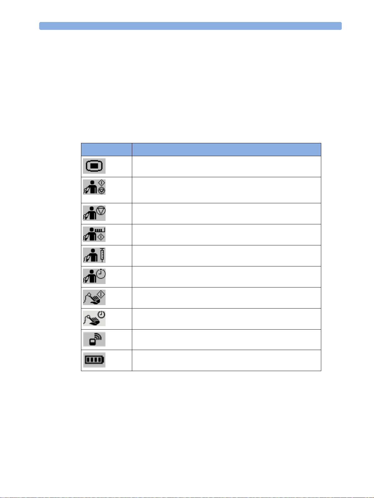
List of Available SmartKeys
SmartKey Text L ab els
Main Setup
- start/stop manual NBP measurement
- start auto series
- stop current automatic measurement within series
stop any NBP measurement and measurement series
Exit screen or press the ► hardkey for a couple of
start NBP STAT measurement
start venipuncture (inflate cuff to subdiastolic pressure)
set the NBP repetition time
start an SpO
set the SpO
Add/Remove device
measurement
2
repetition time
2
enter Battery menu
14
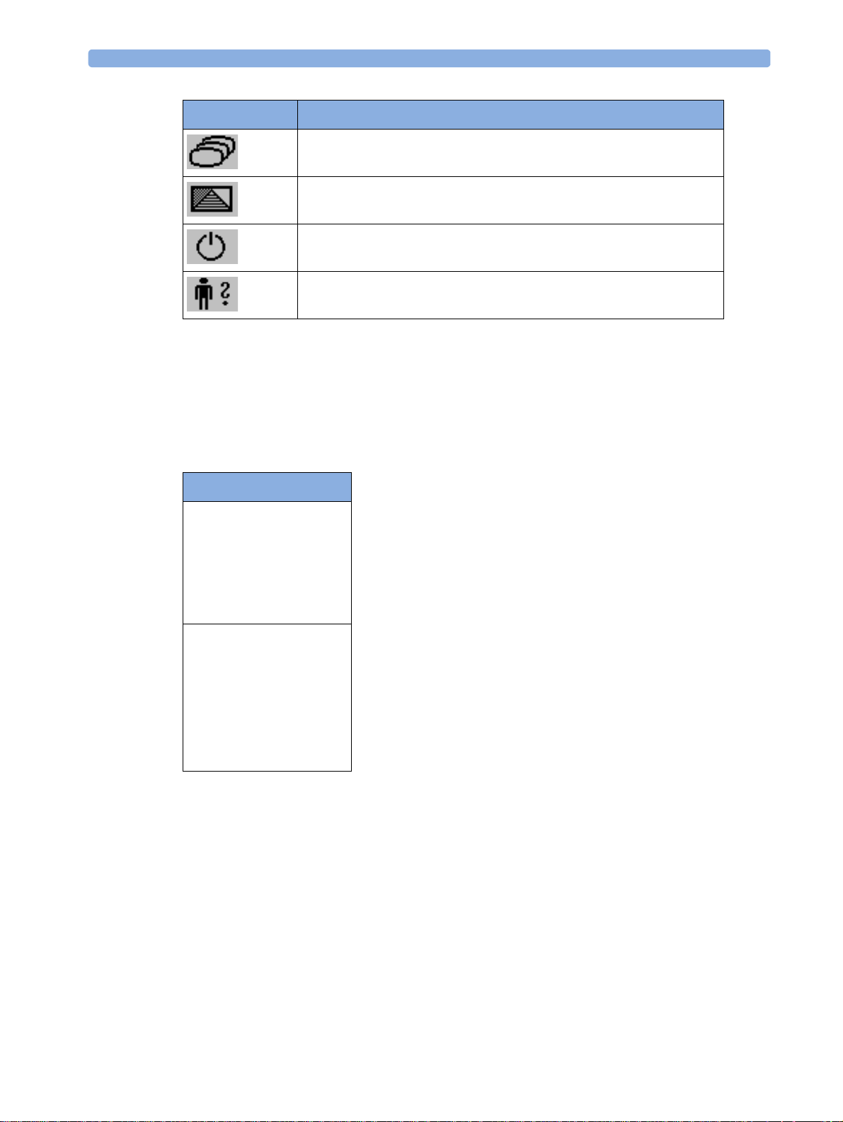
SmartKey Text L ab els
change Screen
enter
Profiles menu
switch device off
Patient menu
enter
Using the Main Setup Menu
In addition to the hard keys and SmartKeys for the most needed functions, the Main Setup menu gets
you to all settings that can be adjusted for the respective device. Select the
to the
Main Setup menu.
1 Introduction and Basic Operation
Main Setup SmartKey to get
Main Setup
SpO₂
INOPs
Patient
Equipment
User Interface
Device Off
Profiles
Operating Modes
Date, Time
Battery
Revisions
Operating Modes
Your device has four operating modes. Some are passcode protected.
• Monitoring Mode: This is the normal, every day working mode that you use for making
measurements. You can change elements such as measurement modes, patient category and so
forth. When you remove the patient from the device, these elements return to their default values.
Changes can be stored permanently only in Configuration Mode. You may see items, such as some
menu options, that are visible but 'grayed out' so that you can neither select nor change them.
These are present for your information only and can be changed only in Configuration Mode.
15

1 Introduction and Basic Operation
• Demonstration Mode: Passcode protected, this is for demonstration purposes only. You must
not change into Demonstration Mode during monitoring.
• Configuration Mode: Passcode protected, this mode is for personnel trained in configuration
tasks. These tasks are described in the Configuration Guide. During installation the Cableless
Measurement Device is configured for use in your environment. This configuration defines the
default settings you work with when you switch on.
• Service Mode: Passcode protected, this is for trained service personnel.
When you switch the device on, it starts up in monitoring mode. To change to a different mode:
1 Use the Main Setup SmartKey to get to the Main Setup menu.
2 Select Operating Modes and choose the mode you require.
Standby Mode
The IntelliVue Cableless Measurement devices do not have standby mode. However, when connected
to a monitor that is in standby mode, the IntelliVue Cableless Measurement Device will show a
standby screen.
Using the Patient Menu
The Patient menu allows you to see patient demographics information and to remove a patient from a
device. Patient Demographic information is only displayed if the Cableless Measurement Device is
assigned to a patient monitor.
at the Cableless Measurement Device, but only when the device is not assigned to a patient monitor or
telemetry device.
Patient Category is the only item of patient data which can be selected
Displaying the Patient Menu
To display the Patient menu,
• select the
• select the
Patient SmartKey, or
Main Setup SmartKey followed by Patient.
Removing a Patient From The Device
To remove a patient from the Cableless Measurement Device,
•in the
All patient data is cleared, settings are reset to the defaults and the device is removed from the monitor
or telemetry device.
Patient menu select Free Device.
Adding a New Patient to the Device
To use a device for a new patient,
•in the
Patient menu, select New Patient.
16
If the device was not free, the existing data will be deleted and the profile set to the default.

Using Profiles
A profile is a set of measurement and general settings which have been customized for a particular
purpose. The Cableless Measurement Devices can have four different profiles configured to your
requirements. The default profile is marked with a symbol. To select a different profile,
1 Select the Profiles SmartKey or the Main Setup SmartKey followed by Profiles.
2 Select the required profile from the list.
1 Introduction and Basic Operation
Selecting
New Patient or Free Device will always reset the profile to the default.
Setting the Date and Time
If the Cableless Measurement Device is assigned to a patient monitor or to a telemetry device, the date
and time will be taken from the host. If this is not the case, you can set the date and time on the
Cableless Measurement Device,
1 Select the Main Setup SmartKey and then Date, Time.
2 Enter the data for date and time one after another.
3 Select Store Date, Time.
If the time has not been set, --:-- will display on the device.
Charging IntelliVue Cableless Measurement Devices
All IntelliVue Cableless Measurement Devices are battery powered and need to be recharged using the
IntelliVue CL Charging Station. The battery is built in and can only be exchanged by trained service
personnel.
To charge a battery, place it onto a charger slot on the charging station. The NBP Pod should always
be placed on one of the slots in the upper row. The battery power indicators will supply information
about the charge status.
WARNING
• Always use the supplied power cord with the grounded mains plug to connect the charging station
to a grounded AC mains socket. Never adapt the mains plug from the power supply to fit an
ungrounded AC mains socket.
• Do not use AC mains extension cords or multiple portable socket outlets. If a multiple portable
socket outlet without an approved isolation transformer is used, the interruption of its protective
grounding may result in enclosure leakage currents equal to the sum of the individual ground
leakage currents, so exceeding allowable limits.
• Do not connect any devices that are not supported as part of a system.
Battery Power Indicators
There are various indications which help you keep track of the battery power status:
• LEDs on the charging station slots
17

1 Introduction and Basic Operation
• battery status information on both the device's and the charging station's display
• INOP messages
• battery icon on the patient monitor's screen (when assigned to a patient monitor)
The indicators always show the remaining capacity in relation to the battery's actual maximum capacity,
which may lessen as the battery ages. You can see the actual capacity in the
Charging Station LEDs
The nine charger slot LEDs show the battery status of the device in their slot, and are switched off if
no device is inserted.
If an IntelliVue Cableless Measurement Device is put on a charging station slot, the corresponding
LED will flash yellow until the device and its current state have been identified. Then a beep is issued
and the LED reflects the device's battery status as described in the table below.
Status LED
no device on charger slot off
device put on charger slot flashing yellow
device not properly recognized, error cyan
device recognized, battery charging yellow
device recognized, battery full (≥90%) green
Battery menu.
The AC Power / Error LED is
• green when the Charging Station is connected to AC power
• cyan during startup or to indicate a general Charging Station error
Battery Status on the Charging Station Display
The IntelliVue CL Charging Station display provides a quick overview of all the connected devices and
their battery status. The screen is arranged in the same layout as the charger slots.
Battery Status on the Cableless Device
All IntelliVue Cableless Measurement Devices show their battery status on their display both in
operating and charging condition. The battery status indicator is located in the lower right corner of
the screen during operation and in the middle of the screen during charging.
Battery Status Menu
Select the battery symbol using the ◄ and ► keys, then press the 9 key to open the Battery menu.
The
Battery menu provides the following information: full-charge and remaining capacity, voltage,
current and temperature.
18

2Monitoring with the IntelliVue
Cableless Measurements
IntelliVue Cableless Measurements Use Models
With these patient-worn measurement devices you can measure and transmit a patient's vitals regularly
or on an intermittent data collection basis. There are two typical use models:
With a Patient Monitor
The SpO2 and the NBP Pods can be used together with an MP5/MP5T, MP2 or X2 patient monitor
(with a SRR interface). They can communicate their measurement values via short range radio to the
monitor. The monitor may be assigned to a patient sector at the IntelliVue Information Center (IIC).
When assigned to the Information Center, certain actions can be performed at both the patient
monitor and the Information Center. See the table “Controls Available with a Patient Monitor” on
page 22.
2
In situations where patients are becoming more mobile (for example, in step-down/intermediate care
units) the lightweight, cableless SpO
radio range, without giving up vital signs monitoring.
When assigned to a patient monitor, the admitted patient name is displayed on the Pod.
A telemetry device can be assigned to a patient monitor equipped with short range radio at the same
time as any SpO
If the connection between the monitor and the NBP Pod or SpO
displayed at the monitor:
will be displayed on the Pod.
and NBP Pods are also assigned to this monitor.
2
With a Telemetry Devi ce
The SpO2 and the NBP Pods can be assigned to a patient with the telemetry device TRx4841A/
TRx4851A. They can communicate their measurement values via short range radio to the telemetry
device which communicates them to an IntelliVue Information Center to provide a consolidated set of
patient values.
Some of the measurement tasks can be performed remotely from the Information Center. See the
table “Controls Available With a Telemetry Device” on page 23.
If the patient name is available at the Information Center, it will be also displayed on the Pod.
and NBP Pods allow increased mobility within the short range
2
Pod is lost, an INOP will be
2
cl SpO₂ Disconnect or cl NBP Disconnect. A No System Monitor. INOP
19

2 Monitoring with the IntelliVue Cableless Measurements
When a cableless measurement device is assigned to a telemetry device, it is not possible for the
telemetry device to be wirelessly assigned or directly connected to a patient monitor.
If the connection between the telemetry device and the NBP Pod or SpO
be displayed at the Information Center:
Monitor. INOP will be displayed on the Pod.
cl SpO₂ Disconnect or cl NBP Disconnect. A No System
Pod is lost, an INOP will
2
Device Compatibility
The Cableless Measurement Devices require the following software levels in the associated equipment:
• Patient Monitor - Release H.0 or above
• Information Center - Release M or above
• Telemetry device TRx4841A/TRx4851A - Revision D.XX
Assigning an IntelliVue Cableless Measurement Device to a Patient Monitor or Telemetry Device
When an IntelliVue Cableless Measurement Device is used with a patient monitor or telemetry device,
the Cableless Measurement Device must be assigned to that monitor/telemetry device.
The assignment can be done at the Cableless Measurement Device itself (this is the only way for a
telemetry device) or at the patient monitor.
WARNING
Short Range Radio connections are subject to interruption due to interference from other radio
sources in the vicinity, including microwaves, bluetooth devices, WLAN devices (802.11b,g,n) and
DECT phones. Depending on the strength and duration of the interference, the interruption may
occur for an extended period. A loss of connection, due to moving out-of-range, interference, or for
other reasons, is indicated with a
cl NBP Disconnect or cl SpO₂ Disconnect INOP at the host monitor. Correct channel configuration
a
is important, refer to the Configuration Guide for details.
No Host Monitoring INOP on the Cableless Measurement Device or
Assignment at the Measur eme nt Dev ice
To make an assignment, select:
• the Assignment SmartKey , or
• the connection status symbol (or if the device is not assigned), or
•hold the ◄ key pressed.
If the device was not assigned, this opens the
monitors and telemetry devices within the SRR range. In order to save power, the list is only visible for
a short time; the menu is automatically closed after 40 seconds.
Add To menu which lists the available patient
20

2 Monitoring with the IntelliVue Cableless Measurements
A telemetry device must be put into assignment mode by pressing the 9 key on the telemetry device
before it can appear in the list. Pressing the 9 key starts an SRR channel search to find the clearest
channel available. During the search all 4 LEDs flash once per second. The search will take
approximately 20-25 seconds. Once a channel is identified, the first LED will light up and blink once
per second to indicate that the telemetry device is ready for assignment.
Add To
Mon 1
Mon 2
Tele 33
Tele 44
1 Select a patient monitor or telemetry system using the ◄ and ► keys.
If you select a patient monitor, the measurement selection key on that monitor will change to show
the type of measurement device.
2 Activate the assignment by pressing the 9 key twice on the measurement device.
The cableless measurement device is assigned to the selected patient monitor or telemetry device.
A telemetry device plays the assignment tone when the assignment is successful. A patient monitor
issues an assignment prompt message.
If the internal measurement in the patient monitor is active (the measurement selection key is yellow),
you will need to confirm that it should be deactivated in favor of the cableless measurement device you
want to assign. To do this:
1 Select the measurement selection key on the monitor.
A prompt message appears with the
2 Select Confirm to deactivate the internal measurement.
Confirm and Cancel keys.
When the cableless measurement device is assigned, the symbol appears on its display indicating
that alarming capability has been transferred to the host (to the monitor or, for the telemetry device, to
the Information Center). No patient alarms will be announced on the Cableless Measurement Device.
If the device was assigned, this opens a menu for the patient monitor or telemetry system. To
unassign the measurement device from that monitor or telemetry system, select
confirmation the SRR connection is disconnected.
Assignment at the Pa tie nt Monitor
The cableless measurement device must be prepared for assignment by activating the Add/Remove
SmartKey.
At the patient monitor,
1 Open the Add Cableless window, e.g. using the measurement selection key followed by the Add
Cbleless
The available cableless measurement devices are shown in the window
pop-up key.
Remove From. After
2 Select the device which you want to assign to the patient in the monitor.
3 The monitor displays the assignment prompt message.
If the internal measurement in the patient monitor is active, you will need to confirm that it should be
deactivated in favor of the cableless measurement device you want to assign.
21

2 Monitoring with the IntelliVue Cableless Measurements
When the cableless measurement device is assigned, the symbol appears on its display indicating
that alarms from the device will be sent to the patient monitor.
An assigned cableless measurement device can be removed in the
Measurement Selection window.
For more details see the Instructions for Use for your patient monitor.
Controls Available wit h a Patient M onitor
The controls available when the Cableless Measurement Device is assigned to a patient monitor are
described in the table below.
Action At Cableless
Measurement
Device
SpO
2
Start SpO
2
Change SpO
Select SpO
2
Assign SpO
Remove SpO
Mode Yes Yes No
2
Repetition Time Yes Yes No
Pod Yes Yes No
2
Pod Yes Yes No
2
Yes Yes No
Change Alarm Limits No Yes No
Place Device in Standby No Yes Yes
Alarm Silence No Yes Yes
Alarm Off/Pause No Yes Yes
At Patient
Monitor
At IIC
NBP
Start/Stop/Stat NBP Yes Yes Yes
Change NBP Mode Yes Yes No
Change NBP Repetition Time Yes Yes No
Change Alarm Limits No Yes No
Assign NBP Pod Yes Yes No
Remove NBP Pod Yes Yes No
Place Device in Standby No Yes Yes
Alarms Silence No Yes Yes
Alarm Off/Pause No Yes Yes
22

2 Monitoring with the IntelliVue Cableless Measurements
WARNING
If a patient being monitored by Cableless Measurement Devices moves out of range of the patient
monitor, the measurements are available on the Cableless Measurement Device only. They are not
transmitted to the patient monitor or the Information Center. If this occurs, the
No Host Monitoring
message is displayed on the measurement device. The measurement device will also sound the INOP
tone. No alarms will be available for the measurements when the devices are out of range, as alarms are
only available on the patient monitor.
Keep the patient monitor with the patient during transport.
Controls Available With a Telemetry Device
The controls available when the Cableless Measurement Device is assigned to a TRx4841/TRx4851A
Transceiver with a short range radio adapter (SRRA) are described in the table below.
Action At the Cableless
At the IIC
Measurement Device
SpO
2
Start SpO
2
Change SpO
Select SpO
2
Assign SpO
Remove SpO
Mode Yes Yes
2
Repetition Time Yes No
Pod Yes No
2
Pod Yes Yes
2
Yes Yes
Change Alarm Limits No Yes
Place Device in Standby No No
Alarm Silence No Yes
Alarm Off/Pause No Yes
NBP
Start/Stop/Stat NBP Yes No
Change NBP Mode Yes No
Change NBP Repetition Time Yes No
Change Alarm Limits No Yes
Assign NBP Pod Yes No
Remove NBP Pod Yes Yes
Place Device in Standby No No
Alarms Silence No Yes
Alarm Off/Pause No Yes
23

2 Monitoring with the IntelliVue Cableless Measurements
NOTE
When you unplug the ECG cable from the telemetry device and plug it into the monitor associated
with the same patient, the ECG source will automatically be from the monitor. The SpO
measurement devices assigned to the telemetry device will continue to source data to the telemetry
device and the Information Center. You may need to change screens on the patient monitor to see the
measurements.
NOTE
The SpO2 measurement sourced from the telemetry device (label: SpO2T) has priority over the
IntelliVue CL SpO
as it is available and the IntelliVue CL SpO
measurement. The SpO2T measurement is sent to the Information Center as long
2
measurement is available on the measurement device only.
2
and/or NBP
2
24

3
3Monitoring SpO2
Philips pulse oximetry uses a motion-tolerant signal processing algorithm, based on Fourier artifact
suppression technology (FAST). A sensor is used that transmits light of two different wavelengths
through the tissue of the patient. The measurement principle of pulse oximetry is based on the specific
absorption characteristics of oxyhemoglobin and deoxyhemoglobin and the pulsating arteriolar
vascular bed at the measurement site. It provides four measurements:
• Oxygen saturation of arterial blood (SpO
the sum of oxyhemoglobin and deoxyhemoglobin (functional arterial oxygen saturation).
• Pleth waveform - visual indication of patient's pulse (only on patient monitor or Information
Center, if assigned).
• Pulse rate (derived from pleth wave) - detected pulsations per minute.
• Perfusion indicator - numerical value for the pulsatile portion of the measured signal caused by
arterial pulsation (only on patient monitor, if assigned).
NOTE
No alarms are generated for SpO2 and Pulse when measuring SpO2 with the SpO2 Pod not assigned to
a host.
SpO2 Sen so rs
Specialized SpO2 Sensors are available for use with the IntelliVue CL SpO2 Pod. See “Accessories” on
page 55 for details.
Familiarize yourself with the instructions for use supplied with your sensor before using it. In
particular, check that the sensor being used is appropriate for your patient category and application
site.
) - percentage of oxygenated hemoglobin in relation to
2
Additional Information
The following documents contain additional information, depending on which accessories you are
using:
• Mobile CL Single-Patient SpO
• Mobile CL Reusable SpO
• Mobile CL SpO
1
may not be available in all geographies
2
Sensor Instructions for Use
2
Sensor1 Instructions for Use
2
Wristband Instructions for Use
25

3 Monitoring SpO2
Connecting SpO2 Sensors
1 Connect the sensor to the single patient Mobile CL SpO
2 Insert the SpO
matching blue dot inside the cradle.
CAUTION
Pod into the Mobile CL SpO2 Cradle. The correct orientation is indicated by a
2
Cradle (if not already connected).
2
Make sure that the contacts of the SpO2 Pod and the sensor are dry and free of residues.
3 Secure the cradle on the patient's arm using the wristband.
a. Feed the free end of the wristband through the slot in the cradle, starting from the underside
of the cradle.
b. Slide the wristband onto the patient's arm and pull the free end until the wristband fits snugly.
c. Close the wristband using the Velcro patch on the free end of the band.
26

Removing the Pod from the Cradle
To remove the SpO2 Pod from the cradle,
3 Monitoring SpO2
pull on the Pod at the opening
in the cradle, while holding the
cradle in place on the patient's
arm.
Applying the Sensor
1 Choose a finger of the patient that matches the sensor dimension in a way that the sensor optical
components are properly aligned and the sensor is neither too loose nor applies too much pressure
to the finger. For small pediatric patients consider the thumb. For large adults the little finger
might be suitable.
2 Remove colored nail polish from the application site.
3 Apply the sensor to the patient. The application site should match the sensor size so that the
sensor can neither fall off, nor apply excessive pressure. See the sections below for details on
applying the different sensors.
4 Check that the light emitter and the photodetector are directly opposite each other. All light from
the emitter must pass through the patient's tissue.
WARNING
Loose Sensor: If a sensor is too loose, it might compromise the optical alignment or fall off. If it is
too tight, for example because the application site is too large or becomes too large due to edema,
excessive pressure may be applied. This can result in venous congestion distal from the application site,
leading to interstitial edema, hypoxemia and tissue malnutrition. Skin irritations or lacerations may
occur as a result of the sensor being attached to one location for too long. To avoid skin irritations and
lacerations, periodically inspect the sensor application site and change the application site at least every
four hours.
Venous Pulsation: Do not apply sensor too tightly as this results in venous pulsation which may
severely obstruct circulation and lead to inaccurate measurements.
Ambient Temperature: At elevated ambient temperatures be careful with measurement sites that are
not well perfused, because this can cause severe burns after prolonged application. All listed sensors
operate without risk of exceeding 41°C on the skin if the initial skin temperature does not exceed
35°C.
27

3 Monitoring SpO2
Extremities to Avoid: Avoid placing the sensor on extremities with an arterial catheter, an NBP cuff
or an intravascular venous infusion line.
Measuring SpO2
During measurement, ensure that the application site:
– has a pulsatile flow, ideally with a perfusion indicator value above 1.0 or, if the perfusion
indicator is not available, with signal quality indicator of at least medium.
– has not changed in its thickness (for example, due to edema), causing an improper fit of the
sensor.
WARNING
• For fully conscious pediatric or adult patients, who have a normal function of perfusion and
sensory perception at the measurement site:
To ensure skin quality and correct optical alignment of the sensor, inspect the application site
when the measurement results are suspicious or when the patient complains about pressure at
the application site, but at least every 24 hours. Correct the sensor alignment if necessary.
Move the sensor to another site, if the skin quality changes.
• For all other patients:
Inspect the application site every two to three hours to ensure skin quality and correct optical
alignment. Correct the sensor alignment if necessary. If the skin quality changes, move the
sensor to another site.
Change the application site at least every four hours.
• Injected dyes such as methylene blue, or intravascular dyshemoglobins such as methemoglobin
and carboxyhemoglobin may lead to inaccurate measurements.
• Inaccurate measurements may result when the application site for the sensor is deeply pigmented
or deeply colored, for example, with nail polish, artificial nails, dye or pigmented cream.
• Interference can be caused by:
– High levels of ambient light (including IR warmers) or strobe lights or flashing lights (such as
fire alarm lamps). (Hint: cover application site with opaque material.)
–Another SpO
performed on the same patient). Always cover both sensors with opaque material to reduce
cross-interference.
– Electromagnetic interference, especially at perfusion numeric values below 1.0 or signal quality
indicator below medium.
– Excessive patient movement and vibration.
sensor in close proximity (e.g. when more than one SpO2 measurement is
2
Selecting Measurement Modes
There are three different modes available for making SpO2 measurements:
28

3 Monitoring SpO2
• Continuous mode - SpO2 is measured continuously until the measurement is switched off.
• Manual mode - a single SpO
SpO₂ menu item is selected. One set of values is then displayed with the time the measurement was
measurement is made when the Start SpO₂ SmartKey or the Start
2
made.
• Automatic mode - a series of measurements is made with an interval between them. The interval
is selected using the
Repeat Time SmartKey or the Repeat menu item. The measurement starts
automatically when automatic mode is selected.
The values measured in manual mode or automatic mode will be displayed for one hour. After that the
values are regarded as invalid and are no longer displayed.
Understanding SpO2 Numerics and Symbols
1 SpO
2 Pulse rate numeric
3 Symbol indicating pulse rate
4 Measurement mode - indicates here that Auto
5 Alarms Off symbol for Pulse
numeric
2
mode is active and shows the time to the next
measurement.
Note: The Alarms Off symbols indicate that no physiological alarms are available from the Cableless
Measurement Devices when not assigned to a host.
SpO2 Signal Quality Indicator
The SpO2 numeric is displayed together with a signal quality indicator (if configured and enough space
is available) which gives an indication of the reliability of the displayed values.
The level to which the triangle is filled shows the quality of the signal; the indicator below shows a
medium signal quality, the signal quality is at a maximum when the triangle is completely filled.
6 Timestamp
7 Alarms Off symbol for SpO
1 SpO
Quality Indicator
2
2
29

3 Monitoring SpO2
Assessing a Suspicious SpO2 Reading
Traditionally, pulse rate from SpO2 was compared with heart rate from ECG to confirm the validity of
the SpO
the correct calculation of SpO
When pulse rate is very low, or strong arrhythmia is present, the SpO
heart rate calculated from ECG but this does not indicate an inaccurate SpO
If you doubt the measured SpO
patient monitor, the pleth wave and perfusion indicator on the monitor to assess the signal quality.
WARNING
With pulse oximetry, sensor movement, ambient light (especially strobe lights or flashing lights) or
electromagnetic interference can give unexpected intermittent readings when the sensor is not
attached. Especially bandage-type sensor designs are sensitive to minimal sensor movement that might
occur when the sensor is dangling.
reading. With newer algorithms, such as FAST-SpO2, this is no longer a valid criteria because
2
is not directly linked to the correct detection of each pulse.
2
pulse rate may differ from the
2
, use the signal quality indicator (if available) or, when used with a
2
value.
2
Changing the Averaging Time
Depending on the monitor configuration, you may be able to change the averaging time for the SpO2
values.
The averaging time represents the approximate time period used for the calculation. The exact
averaging time also depends on the signal conditions. The longer the averaging time, the longer the
time needed until the SpO
numerical values: SpO
averaging is useful for situations where an extremely fast measurement is required or few artifacts are
expected. Use slow averaging where you expect the number of artifacts to be relatively high.
1 In the SpO₂ menu, select Average.
2 Select the required averaging time from the list.
values reflect the physiological event. The same averaging is applied to all
2
, pulse rate and Perfusion Index (only available at the patient monitor). Fast
2
Understanding SpO2 Alarms
If you are using the SpO2 pod with an assigned patient monitor, you will see SpO2 alarms and pulse
rate alarms (if configured) on the monitor.
There is a delay between a physiological event at the measurement site and the corresponding alarm at
the host system. This delay has two components:
• The general system delay time is the time between the occurrence of the physiological event and
when this event is represented by the displayed numerical values. This delay depends on the
algorithmic processing and the configured averaging time. The longer the averaging time
configured, the longer the time needed until the numerical values reflect the physiological event.
30

3 Monitoring SpO2
• The time between the displayed numerical values crossing an alarm limit and the alarm indication
on the monitor. This delay depends on the host system.
Refer to the Instructions for Use of the monitor for information about the SpO
and pulse rate alarms.
2
Perfusion Numeric (only available on the Patient Monitor)
The perfusion numeric (Perf) gives a value for the pulsatile portion of the measured signal caused by
the pulsating arterial blood flow.
You can also use the perfusion numeric as a quality indicator for the SpO
optimal, between 0.3-1 is acceptable. Below 0.3 is marginal; reposition the sensor or find a better site.
measurement. Above 1 is
2
31

3 Monitoring SpO2
32

4
4Monitoring NBP
The IntelliVue CL NBP Pod uses the oscillometric method for measuring NBP. The blood pressure
measurements determined with this device comply with the American National Standard for
Electronic or Automated Sphygmomanometers (ANSI/AAMI SP10:2002/(R)2008 + A1:2003/
(R)2008) in relation to mean error and standard deviation, when compared to auscultatory
measurements (depending on the configuration) in a representative patient population. The fifth
Korotkoff sound was used to determine the diastolic pressure.
The accuracy of the mean arterial pressure (MAP) was validated by comparative laboratory testing to
the M3000A Multi-Measurement Server using an NBP simulator and a patient signal database. The
accuracy of the MAP of the M3000A was validated in a clinical evaluation using the intra-arterial
reference method.
The NBP measurement is suitable for use in the presence of electrosurgery and during the discharge of
a cardiac defibrillator according to IEC 60601-2-30:1999/EN 60601-2-30:2000.
A physician must determine the clinical significance of the NBP information.
Introducing the Oscillometric NBP Measurement
Oscillometric devices measure the amplitude of pressure changes in the occluding cuff as the cuff
deflates from above systolic pressure. The amplitude suddenly increases as the pulse breaks through
the occlusion in the artery. As the cuff pressure decreases further, the pulsations increase in amplitude,
reach a maximum (which approximates to the mean pressure), and then diminish.
Studies show that, especially in critical cases (arrhythmia, vasoconstriction, hypertension, shock),
oscillometric devices are more accurate and consistent than devices using other noninvasive measuring
techniques.
WARNING
Patient Category: Do not use the IntelliVue CL NBP Pod on neonatal patients. The initial inflation
pressure and overpressure safety limits are too high for neonatal patients and could cause fractures and
bruises.
Intravenous infusion: Do not use the NBP cuff on a limb with an intravenous infusion or arterial
catheter in place. This could cause tissue damage around the catheter when the infusion is slowed or
blocked during cuff inflation.
Skin Damage: Do not measure NBP in cases of sickle-cell disease or any condition where skin
damage has occurred or is expected.
33

4 Monitoring NBP
Unattended measurement: Use clinical judgement to decide whether to perform frequent
unattended blood pressure measurements in cases of severe blood clotting disorders because of the
risk of hematoma in the limb fitted with the cuff.
CAUTION
If you spill liquid onto the equipment or accessories, particularly if there is a chance that it can get
inside the tubing or the measurement device, contact your service personnel.
Measurement Limi tations
Measurements are impossible with heart rate extremes of less than 40 bpm or greater than 300 bpm, or
if the patient is on a heart-lung machine.
The measurement may be inaccurate or impossible:
• with excessive and continuous patient movement such as shivering or convulsions
• if a regular arterial pressure pulse is hard to detect
• with cardiac arrhythmias
• with rapid blood pressure changes
• with severe shock or hypothermia that reduces blood flow to the peripheries
• with obesity, where a thick layer of fat surrounding a limb dampens the oscillations coming from
the artery
• on an edematous extremity.
The effectiveness of this sphygmomanometer has not been established in pregnant, including preeclamptic patients.
Measurement Modes
There are four modes for measuring NBP:
•
Manual - measurement on demand.
•
Auto - continually repeated measurements (between one minute and 24 hours adjustable interval).
•
Sequence - up to four measurement cycles which will run consecutively, with number of
measurements and interval between them configurable for each cycle.
•
STAT - rapid series of measurements over a five minute period, then the monitor returns to the
previous mode. Use only on supervised patients.
Reference Me th o d
The measurement reference method is always Auscultatory (manual cuff). For further information, see
the Application Note supplied on the documentation DVD.
34

Preparing to Measure NBP
1 Attach the cradle to the NBP cuff and insert the NBP Pod into the cradle.
2 Plug the air tubing into the NBP Pod. Hold the flat part of the connector vertically when plugging
it into the inlet, then twist it clockwise to lock into place. Avoid compression or restriction of
pressure tubes. Air must pass unrestricted through the tubing.
4 Monitoring NBP
3 Make sure that you are using a Philips-approved correct sized cuff and that the bladder inside the
cover is not folded or twisted.
A wrong cuff size, and a folded or twisted bladder, can cause inaccurate measurements. The width
of the cuff should be in the range from 37% to 47% of the limb circumference.
4 Apply the cuff to the upper arm at the same level as the heart. If it is not at heart level, you must
use the measurement correction formula to correct the measurement.
CAUTION
Make sure that the air vent, located next to the air tubing connector on the NBP Pod, is not
covered during operation. If air cannot enter the air vent, the pump may be damaged.
Apply the cuff so that the NBP Pod is located at the outside of the arm. The bladder of the cuff is
then automatically over the artery. Make sure that the D-ring is not over the artery as this can lead
to missing or inaccurate readings. Do not wrap the cuff too tightly around the limb. It may cause
discoloration, and ischemia of the extremities. Inspect the application site regularly to ensure skin
quality and inspect the extremity of the cuffed limb for normal color, warmth and sensitivity. If the
skin quality changes, or if the extremity circulation is being affected, move the cuff to another site
or stop the blood pressure measurements immediately. Check more frequently when making
automatic or stat measurements.
Additional Information
The following documents contain additional information, depending on which accessories you are
using:
• Mobile CL Reusable NBP Cuffs Instructions for Use
35

4 Monitoring NBP
• Mobile CL Single-Patient NBP Cuffs Instructions for Use
• Mobile CL NBP Cradle Instructions for Use
• Mobile CL Extension Air Hose Instructions for Use
Using a Carrying Pou ch
As an alternative to fixing the NBP Pod on the cuff, you can insert it in a telemetry pouch which can
be worn. In this case the NBP Pod is connected via an extension hose to the cuff.
1 Apply the cuff as described in step 4 above.
2 Secure the pouch on the patient, with the upper ties around the patient's head and arm and the
lower ties around the patient's torso.
3 Insert the NBP Pod into the cradle.
4 Attach the extension hose to the NBP Pod in the cradle.
5 Insert the NBP cradle into the pouch
6 Connect the extension hose to the cuff.
See the Accessories chapter for ordering details for pouches and extension hose.
Starting and Stopping Measurements
Use the setup menu or SmartKeys to start and stop measurements.
Action to be Performed NBP Setup menu SmartKeys
Start manual measurement
Start Auto series
Start STAT measurement
Stop Manual measurements
Stop current Auto measurement
Stop current STAT measurement and
end STAT mode
Start/Stop
Start NBP Stat
Start/Stop
Start/Stop
Start/Stop
Start/Stop
Start NBP STAT
Start/Stop
Start/Stop
36
Stop Auto, Manual or STAT
measurement, end STAT mode AND
Auto/Sequence series
Start/Stop
Stop All
Stop All

4 Monitoring NBP
CAUTION
Use clinical judgment to decide whether to perform repeated series of STAT measurements because of
the risk of purpura, ischemia and neuropathy in the limb with the cuff.
Enabling Automatic Mode and Setting Repetition Time
1 In the NBP menu, select Mode and select Auto from the pop-up menu.
2 For an automatic measurement, select Repeat and set the time interval between two
measurements.
Enabling Sequence Mode and Setting Up The Sequence
1 In the NBP menu, select Mode and select Sequence from the pop-up menu.
2 Select Setup Sequence to open the Setup Sequence menu.
Up to four measurement phases can be setup which will run consecutively. For each phase you can
set the number of measurements and the interval between them. If you want to run less than four
phases in a sequence, you can set the number of measurements for one or more phases to
3 Select each phase in turn (A, B, C and D) and select the number of measurements and the time
interval between the measurements.
4 To have measurements continue after the sequence, set the number of measurements for your last
phase to
CAUTION
Be aware that, if none of the phases are set to Cont, NBP monitoring will end after the last
measurement of the phase.
When the NBP measurement mode is set to Sequence, the repetition time for Auto mode cannot be
changed.
Cont and this phase will run indefinitely.
Off.
37

4 Monitoring NBP
Understanding the NBP Numerics and Symbols
1 Systolic/Diastolic pressure
2 Mean pressure
3 Pulse rate
4 Pulse rate indicator
5 Measurement mode (see below)
6 Alarms Off symbol for Pulse
7 Timestamp
8 Alarms Off symbol for NBP
Note: The Alarms Off symbols indicate that no physiological alarms are available on the Cableless
Measurement Devices when not assigned to a host.
Measurement modes with a series of measurements can be indicated with two different symbols:
indicates that a series is running and
shows the relative time to the next
measurement.
An S in front of the symbol indicates
the sequence is currently running.
Sequence mode and an A, B, C or D indicates which phase of
indicates that auto or sequence mode is
selected but the measurement series has
not yet started.
During Measurements
The cuff pressure is displayed instead of the timestamp.
Correcting the Measure ment if Limb is not at Heart Level
To correct the measurement if the limb is not at heart level, to the displayed value
add 0.75 mmHg (0.10 kPa) for each centimeter
higher or
add 1.9mmHg (0.25kPa) for each inch higher. deduct 1.9mmHg (0.25kPa) for each inch
deduct 0.75 mmHg (0.10 kPa) for each
centimeter lower or
lower.
Switching Pulse from NBP On/Off
In the process of making the NBP measurement, a pulse value can be derived and displayed. The pulse
value is displayed together with the time the measurement was made. After one hour the value
becomes invalid.
To switch the display of the pulse value on or off:
38

•In the NBP menu select Pulse.
Assisting Venous Puncture
You can use the NBP cuff to cause sub-diastolic pressure. The cuff deflates automatically after a set
time (adult/pediatric 170 seconds) if you do not deflate it.
1 In the NBP menu select Veni Puncture, or select the Veni Puncture SmartKey.
2 Puncture vein and draw blood sample.
3 Reselect Veni Puncture to deflate the cuff.
During measurement, the NBP display shows the inflation pressure of the cuff and the remaining time
in venous puncture mode.
Calibrating NBP
NBP is not user-calibrated. Cuff-pressure transducers must be verified and calibrated, if necessary, at
least once every two years by a qualified service professional. See the Service Guide for details.
4 Monitoring NBP
39

4 Monitoring NBP
40

5
5Technical Alarms (INOPs)
Technical alarms, also known as INOPs, indicate that the measuring device cannot measure reliably. If
an INOP interrupts monitoring (for example,
place of the measurement numeric. An INOP tone sounds at the Cableless Measurement Device only
when there is no SRR connection to a monitor.
Some INOPs have a severity indication: !! for a medium severity INOP and !!! for a high severity
INOP.
NOTE
The IntelliVue Cableless Measurements do not provide physiological alarms locally on the IntelliVue
CL SpO
Pod and the IntelliVue CL NBP Pod.
2
NBP INTERRUPTED), there will be a question mark in
Display of INOPs
INOP messages are shown in black on a light gray background and coded according to their severity:
A status or INOP message that appears is automatically highlighted. Use the 9 key to acknowledge the
message. An acknowledge message is displayed at the bottom of the screen and highlighted. Press 9
again to confirm the acknowledgment of the INOP. After the confirmation, any ongoing INOP
message is displayed in the icon tray on the right side of the screen.
Acknowled ging an INO P
To acknowledge an INOP, select the INOP message and press the 9 key.
This will silence the INOP tone and clear the INOP message. If the condition which caused the INOP
is still present, the INOP icon will be displayed on the right hand side of the screen (see “INOP
Layout” on page 12).
Displaying a List of Current INOPs
To display a list of the currently active INOPs,
1 Select the Main Setup SmartKey.
2 Select INOPs.
3 Select INOP Messages Messages
41

5 Technical Alarms (INOPs)
Setting the Volume of the INOP Tone
To set the volume for the INOP tone,
1 Select the Main Setup SmartKey.
2 Select INOPs.
3 Select Inop Vol and select a volume setting.The maximum is 10 and the minimum depends on
your configuration.
Reference List of all IN OPs
INOP Message, Indication Source What to do
Batt Incompatible
INOP tone
Batt Malfunction
INOP tone
Battery Empty
INOP tone
Battery Low
INOP tone
Check Batt Temp
INOP tone
Check Battery
INOP tone
Check Charger I/F
INOP tone
Check Settings
INOP tone
Battery Battery cannot be used with this Cableless Measurement
Device. Replace battery with one that has been approved
for use with this Cableless Measurement Device. Contact
your service personnel.
Battery Malfunction of the battery system detected (charger
circuit or battery). Contact your service personnel.
Battery The remaining monitoring time is below 30 minutes.
Charge battery.
Battery The remaining monitoring time is below 2 hours.
Battery The temperature of the battery is critically high. Check
that Cableless Measurement Device is not covered and
not exposed to a heat source. If INOP persists, remove
Cableless Measurement Device from patient and contact
your service personnel.
Battery The maximum number of charge/discharge cycles of the
battery will be reached in less than 50 cycles. Contact
your service personnel to replace the battery.
Battery Overvoltage or undervoltage detected at the charger
interface. Clean contacts of charger interface at Cableless
Measurement Device and charging station. If the INOP
persists, contact your service personnel.
Cableless
Measurement Device
If this INOP appears and an INOP tone sounds, check
the Cableless Measurement Device and patient settings
before you resume making measurements. If the settings
are unexpected, there may be a problem with the
Cableless Measurement Device software. Contact your
service personnel.
42
If this INOP is acknowledged at the Cableless
Measurement Device, it is cleared. If it is silenced
remotely, only the tone is cleared.

INOP Message, Indication Source What to do
5 Technical Alarms (INOPs)
cl NBP Disconnect
at Information Center or at patient
monitor
cl SpO₂ Disconnect
at Information Center or at patient
monitor
CUFF NOT DEFLATED
Numeric is replaced by -?INOP tone
During this INOP, alarms cannot
be paused or switched off.
NBP CUFF OVERPRESS
Numeric is replaced by -?INOP tone
During this INOP, alarms cannot
be paused or switched off.
NBP EQUIP MALF
Numeric is replaced by -?INOP tone
NBP INTERRUPTED
Numeric is replaced by -?INOP tone
NBP MEASURE FAILED
Numeric is replaced by -?INOP tone
Cableless
Measurement Device
Cableless
Measurement Device
The NBP Pod has lost the SRR connection to the
telemetry device or the patient monitor.
The SpO
Pod has lost the SRR connection to the
2
telemetry device or the patient monitor.
NBP The NBP cuff pressure has exceeded 15mmHg (2kPa) for
more than 3 minutes.
Remove the cuff from the patient. Make sure that the
tubing is not kinked or twisted and that the correct
patient category is selected. Try repeating the
measurement. You can acknowledge the INOP, but the
INOP message remains visible until the next NBP
measurement is started or the
Stop All SmartKey is
selected.
NBP The NBP cuff pressure exceeds the overpressure safety
limits. Remove the cuff from the patient. Make sure that
the tubing is not kinked or twisted and that the correct
patient category is selected. Try restarting the
measurement. You can acknowledge this INOP, but the
INOP message remains visible until the next
measurement is started or the
Stop All SmartKey is
selected.
NBP Remove the NBP Pod and cuff from the patient. The
NBP hardware is faulty. Contact your service personnel.
You can acknowledge this INOP, but the INOP message
remains visible until the next measurement is started or
the
Stop All SmartKey is selected.
NBP Check the tubing and cuff for leakages or kinks. Check
that you are using the correct cuff size and placement,
and that the correct patient category is selected. Try
restarting the measurement. If the INOP occurs
repeatedly, contact your service personnel. You can
silence this INOP, but the INOP message remains visible
until the next measurement is started or the
Stop All
SmartKey is selected. This INOP arises when the
measurement needed longer than the maximum time for
inflation, deflation or the total measurement.
NBP Check that you are using the correct cuff size and
placement, and that the correct patient category is
selected. Try restarting the measurement. You can silence
this INOP, but the INOP message remains visible until
the next measurement is started or the
Stop All
SmartKey is selected. Check the condition and suitability
of the patient for NBP monitoring. Use another cuff to
continue measuring.
43

5 Technical Alarms (INOPs)
INOP Message, Indication Source What to do
NBP Neo Patient?
NBP The patient monitor that the NBP pod is assigned to is in
Numeric is replaced by -?INOP tone
No Cradle
NBP The NBP Pod is not in the cradle. You can silence this
Numeric is replaced by -?INOP tone
No Host Monitoring
INOP tone
No System Monitor. Cableless
Cableless
Measurement Device
Measurement Device
Remove From Pat
INOP tone
Service Battery
Cableless
Measurement Device
Battery Maximum number of charge/discharge cycles for battery
INOP tone
<SpO₂ Label> EQUIP MALF
SpO
2
Numeric is replaced by -?INOP tone
<SpO₂ Label> ERRATIC
SpO
2
Numeric is replaced by -?INOP tone
<SpO₂ Label> EXTD.UPDATE
SpO
2
Numeric is replaced by -?-
<SpO₂ Label> INTERFERNCE
SpO
2
Numeric is replaced by -?INOP tone
<SpO₂ Label> LOW PERF
SpO
2
Numeric is replaced by -?-
<SpO₂ Label> NeoPatient?
SpO
2
Numeric is replaced by -?INOP tone
neonatal mode or a neonatal cuff has been detected. The
monitor must be in adult or pediatric mode.
INOP, but the INOP message remains visible until the
NBP Pod is inserted into the cradle and the next
measurement is started or the
Stop All SmartKey is
selected.
If INOP appears with the NBP Pod inserted into the
cradle, remove and replace the cradle.
There is a problem with the communication to the
assigned patient monitor and monitoring is currently not
possible (no patient alarms or information). Check the
connection. Contact your service personnel.
There is a problem with the communication to the
network and central monitoring is currently not possible.
Check the connection. Contact your service personnel.
Displayed on the Cableless Measurement Device. The
temperature of the battery is too high. Remove the
Cableless Measurement Device from the patient and
contact service personnel.
exceeded. Charging of the battery is inhibited. Contact
your service personnel to replace battery.
The SpO2 Pod is faulty. Contact your service personnel.
Check the sensor placement. Try another adapter cable
and sensor. If the INOP persists, contact your service
personnel.
The update time for displayed values is extended due to
an NBP measurement on the same limb or an excessively
noisy signal.
There is too much interference, caused by a high level of
ambient light and/or electrical interference. Cover the
sensor to minimize ambient light. If the INOP persists,
make sure that the sensor cable is not damaged or
positioned too close to power cables.
Accuracy may be compromised due to very low
perfusion. Stimulate circulation at sensor site. If INOP
persists, change the measurement site.
The patient monitor the SpO2 Pod is assigned to is in
neonatal mode. The INOP will remain active until the
monitor is changed to adult or pediatric mode.
44

INOP Message, Indication Source What to do
5 Technical Alarms (INOPs)
<SpO₂ Label> NO SENSOR
SpO
Numeric is replaced by -?INOP tone
<SpO₂ Label> NOISY SIGN.
SpO
Numeric is replaced by -?INOP tone
<SpO₂ Label> NON-PULSAT.
SpO
Numeric is replaced by -?INOP tone
<SpO₂ Label> POOR SIGNAL SpO
<SpO₂ Label> PULSE?
SpO
Numeric is replaced by -?INOP tone
<SpO₂ Label> SEARCHING
SpO
Numeric is unavailable
<SpO₂ Label> SENSOR MALF
SpO
Numeric is replaced by -?INOP tone
<SpO₂ Label> SENSOR OFF
SpO
Numeric is replaced by -?INOP tone
<SpO₂ Label> UNKN.SENSOR
SpO
Numeric is replaced by -?INOP tone
<SpO₂ Label> UPGRADE
SpO
Numeric is replaced by -?-
2
Make sure the SpO2 sensor is connected. If the INOP
persists, try another sensor. If you acknowledge this
INOP, the measurement will be switched off.
2
Excessive patient movement or electrical interference is
causing irregular pulse patterns. Try to reduce patient
movement or to relieve the cable strain on the sensor.
2
Check the perfusion at the measurement site. If
necessary, stimulate circulation or change the
measurement site. If the INOP is due to an NBP
measurement on the same limb, wait until the NBP
measurement is finished.
2
The signal quality of the SpO2 measurement is poor. The
accuracy may be compromised.
2
The detectable pulsations of the SpO2 signal are outside
the specified pulse rate range.
2
The patient signal is analyzed, but no valid numerics are
available yet.
2
The SpO2 sensor is faulty. Try another sensor. If the
INOP persists, contact your service personnel.
2
The algorithm has determined that a sensor is connected,
but not properly applied to the patient. The ability of the
algorithm to detect this condition depends on the used
sensor type.
2
The connected SpO2 sensor is not supported by this
measurement hardware.
2
SpO2 in upgrade mode, no patient monitoring possible.
45

5 Technical Alarms (INOPs)
46

Use only the Philips-approved substances and methods listed in this chapter to clean or disinfect your
equipment. Warranty does not cover damage caused by using unapproved substances or methods.
Philips makes no claims regarding the efficacy of the listed chemicals or methods as a means for
controlling infection. Consult your hospital’s Infection Control Officer or Epidemiologist. For
comprehensive details on cleaning agents and their efficacy refer to “Guideline for Disinfection and
Sterilization in Healthcare Facilities” issued by the U.S. Department of Health and Human Services,
Public Health Service, Centers for Disease Control, Atlanta, Georgia, 2008. See also any local policies
that apply within your hospital, and country.
General Points
Keep your IntelliVue Cableless Measurement devices and accessories free of dust and dirt. After
cleaning and disinfection, check the equipment carefully. Do not use if you see signs of deterioration
or damage. If you need to return any equipment to Philips, decontaminate it first.
6
6Care and Cleaning
Observe the following general precautions:
• Always dilute according to the manufacturer’s instructions or use lowest possible concentration.
• Do not allow liquid to enter the case.
• Do not immerse any part of the equipment or any accessories in liquid if it is not explicitly allowed
and described in the respective accessory Instructions for Use.
• Do not pour liquid onto the charging station.
• Never use abrasive material (such as steel wool or silver polish).
WARNING
If you spill liquid on the charging station or accessories, or if any device or accessory is accidentally
immersed in liquid, contact your service personnel or Philips service engineer. Do not operate the
equipment before it has been tested and approved for further use.
47

6 Care and Cleaning
Cleaning and Disinfecting the IntelliVue Cableless Measurements
The following instructions apply to the IntelliVue CL SpO2 Pod, the IntelliVue CL NBP Pod, the
corresponding single patient Mobile CL Cradles and the IntelliVue CL Charging Station. Clean with a
lint-free cloth, moistened with warm water (40°C/104°F maximum) and soap, a diluted non-caustic
detergent, tenside, ammonia- or alcohol-based cleaning agent. Do not use strong solvents such as
acetone or trichloroethylene.
CAUTION
Solutions: Do not mix disinfecting solutions (such as bleach and ammonia) as hazardous gases may
result.
Hospital policy: Disinfect the product as determined by your hospital’s policy only using the cleaning
agents specified below, to avoid long term damage to the cableless device.
Drying devices: Do not use heat sources, such as ovens or hairdryers, to dry the Pods. Do not put the
Pods in a microwave.
No sterilizing: Do not put the Pods in an autoclave, the devices are not sterilizable.
Rinse the SpO2 Pod and the NBP Pod in water, paying special attention to the contact area to remove
all residues. Wipe them dry with a clean cloth and then leave them to dry completely.
Do not allow any liquid to enter the charging station case and avoid pouring it on the charging station
while cleaning.
The wristbands used with the Mobile CL SpO
or disinfected.
Refer to the accessory Instructions for Use for cleaning and disinfection information for SpO
NBP cuffs and hoses.
Cradles are single-patient items and cannot be cleaned
2
Recommended Disinfection Agents
We recommend that you use one of the following disinfectants:
Product Name Product Type Ingredients
Isopropanol liquid Isopropanol 80%
Bacillol® AF liquid, spray 100 g concentrate contains:
Propan-1-ol 45.0 g; Propan-2-ol 25.0 g; Ethanol 4.7 g
Bacillol®25 liquid Ethanol 100 mg/g
Propan-2-ol (= 2-Propanol) 90 mg/g; Propan-1-ol (= 1Propanol) 60 mg/g
Meliseptol® spray 50% 1-Propanol
Accel TB RTU liquid 0.5% accelerated hydrogen peroxide
Oxivir® Tb Cleaner Disinfectant spray 0.5% accelerated hydrogen peroxide
Oxivir® Tb Wipes wipes 0.5% accelerated hydrogen peroxide
sensors,
2
48

Product Name Product Type Ingredients
Carpe Diem
TM/MC
Tb
spray 0.5% accelerated hydrogen peroxide
Ready-to-Use General Virucide,
Bactericide, Tuberculocide,
Fungicide, Sanitizer
Carpe Diem
Super Sani-Cloth
Germicidal Disposable Wipes
SANI-CLOTH® PLUS
Germicidal Disposable Wipes
SANI-CLOTH® HB Germicidal
Germicidal Disposable Wipes
TM/MC
Tb Wipes wipes 0.5% accelerated hydrogen peroxide
wipes isopropanol 55%
quaternary ammonium chlorides 0.5%
wipes isopropanol 15%
quaternary ammonium chlorides 0.25%
wipes isopropanol < 0.15%
quaternary ammonium chlorides 0.14%
Refer to the accessory Instructions for Use for cleaning and disinfection information for SpO2 sensors,
NBP cuffs and hoses.
6 Care and Cleaning
49

6 Care and Cleaning
50

7
7Maintenance and
Troubleshooting
WARNING
Schedule: Failure on the part of the responsible individual hospital or institution employing the use of
this equipment to implement a satisfactory maintenance schedule may cause undue equipment failure
and possible health hazards.
Contact: If you discover a problem with any of the equipment, contact your service personnel, Philips,
or your authorized supplier.
Inspecting the Equipment and Accessories
You should perform a visual inspection before every use, and in accordance with your hospital's policy.
With the device switched off:
1 Examine unit exteriors for cleanliness and general physical condition. Make sure that the housings
are not cracked or broken, that everything is present, that there are no spilled liquids and that there
are no signs of abuse.
2 Inspect all accessories (cables, sensors and so forth). If any show signs of damage, do not use
them.
WARNING
If the IntelliVue Cableless Measurement Device is mechanically damaged, or if it is not working
properly, do not use it for any monitoring procedure on a patient, contact your service personnel.
Maintenance Task and Test Schedule
All maintenance tasks and performance tests are documented in detail in the service documentation
supplied on the IntelliVue Cableless Measurements documentation DVD. These tasks are for Philipsqualified service professionals only.
51

7 Maintenance and Troubleshooting
Ensure that these tasks are carried out as indicated by the device's maintenance schedule, or as
specified by local laws. Contact a Philips-qualified service provider if your device needs a safety or
performance test. Clean and disinfect equipment to decontaminate it before testing or maintaining it.
Troubleshooting
If a device will not switch on when you press a key, place it onto a charger slot on the charging
station.
If you suspect a problem with an individual measurement device, read the Instructions for Use
and double check that you have set up the measurement correctly. Check also that the measurement
has not been switched off at the patient monitor that the device is assigned to.
If you suspect an intermittent, system-wide problem call your service personnel.
Disposing of the Int elliVue Cabl eless Measurement Devices
WARNING
To avoid contaminating or infecting personnel, the environment or other equipment, make sure you
disinfect and decontaminate the IntelliVue Cableless Measurement Devices appropriately before
disposing of them in accordance with your country's laws for equipment containing electrical and
electronic parts. For disposal of parts and accessories, where not otherwise specified, follow local
regulations regarding disposal of hospital waste.
You will find detailed disposal information on the following webpage:
http://www.healthcare.philips.com/in_en/about/Sustainability/Recycling/pm.wpd
The Recycling Passports located there contain information on the material content of the equipment,
including potentially dangerous materials which must be removed before recycling (for example,
batteries and parts containing mercury or magnesium).
Do not dispose of waste electrical and electronic equipment as unsorted municipal waste. Collect it
separately, so that it can be safely and properly reused, treated, recycled, or recovered.
For information in disposal of accessories, refer to the accessory Instructions for Use.
52

8Integrated Battery Handling
Battery Care
Battery care begins when you receive a new IntelliVue Cableless Measurement Device with built-in
battery and continues throughout the life of the device. The table below lists battery care activities and
when they should be performed.
Activity When to perform
Perform a visual inspection Before using the IntelliVue Cableless Measurement Device
Charge the battery Upon receipt, after use, or if a low battery state is indicated.
Store the device in a state of charge in
the range of 40 - 50% and switch off the
device completely.
8
To optimize performance, a fully (or almost fully)
discharged battery should be charged as soon as possible.
When not in use for an extended period of time.
Handling Precautions
Lithium ion batteries store a large amount of energy in a small package. Use caution when handling the
IntelliVue Cableless Measurement Devices with built-in battery; misuse or abuse could cause bodily
injury and/or property damage.
•Handle with care.
• Do not expose the device to liquids.
• Do not attempt to disassemble the device.
• Do not put device in autoclave.
• Damaged devices should not be used anymore.
WARNING
• Do not crush or puncture - mechanical abuse can lead to internal damage and internal short
circuits which may not be visible externally.
• Do not incinerate the devices or expose them to temperatures above 60°C (140°F).
53

8 Integrated Battery Handling
Storage
If unused IntelliVue Cableless Measurement Devices are stored for an extended period of time:
• they should be powered off for storage
• they should be stored in a cool place, ideally between 15°C and 25°C (60°F and 77°F)
• the state of charge should be between 40 and 50%
• they should be recharged every six months
Storing in a cool place slows the aging process of the batteries. They should be fully charged prior to
use. Do not store the device at a temperature outside the range of -20°C (-4°F) to 60°C(140°F).
Do not store cableless devices in direct sunlight.
NOTE
Storing the devices at temperatures above 40°C (104°F) for extended periods of time could
significantly reduce the battery's life expectancy.
Battery Lifetime Management
The lifetime of a Lithium Ion battery depends on the frequency and duration of use. When properly
cared for, the useful life is approximately 4 years or 400 complete charge-discharge cycles, whichever
comes first. In addition, experience indicates that the incidence of failure may increase with battery
service life due to the accumulated stresses of daily use. We therefore strongly recommend that lithium
ion batteries be replaced after 4 years or 400 complete charge-discharge cycles.
The age of a lithium ion battery begins at the date of manufacture. To see the date of manufacture and
the number of charge-discharge cycles:
1 Select the battery symbol on the Main Screen.
2 Press the ► hardkey to view the battery details.
The date of manufacture and the number of charge-discharge cycles are listed with other battery data
on the screen.
54

9
9Accessories
You can order parts and accessories from Philips supplies at www.medical.philips.com or consult your
local Philips representative for details.
WARNING
Reuse: Never reuse single-patient sensors, accessories and so forth that are intended for single use, or
single patient use only. Reuse may compromise device functionality and system performance and cause
a potential hazard, in particular with regard to cross-contamination.
Philips’ approval: Use only Philips-approved accessories. Using non-Philips-approved accessories
may compromise device functionality and system performance and cause a potential hazard.
IntelliVue CL SpO2 Pod Accessories
All listed sensors operate without risk of exceeding 41°C on the skin, if the initial skin temperature
does not exceed 35°C.
Make sure that you use only the accessories that are specified for use with this device, otherwise patient
injury can result.
Order Number Description Contents
20 Single-Patient Mobile CL DSpO
989803165941 Mobile CL 20 single patient SpO
Sensors and Cradles for use on pediatric
and adult patients >10kg
989803165921 Mobile CL 20 single patient SpO
Sensors for use on pediatric and adult
patients >10kg
2
2
Sensors
20 Single-Patient Wristbands
20 Single-Patient Cradles
pre-assembled
20 Single-Patient Mobile CL DSpO
Sensors
-1A
2
-1A
2
55

9 Accessories
Order Number Description Contents
9898031659311Mobile CL reusable SpO2 sensor and
Cradles for use on pediatric and adult
patients >15kg
989803165951 Mobile CL 20 SpO
patient)
989803165961 Mobile CL 50 SpO
patient)
989803168861 Mobile CL SpO
1
May not be available in all geographies
Cradles (single
2
Wristbands (single
2
Battery Kit 1 Battery
2
1 Reusable Mobile CL RSpO2-1A Sensor
20 Single-Patient Cradles with preattached Wristbands
20 Single-Patient Cradles with preattached Wristbands
50 Single-Patient Wristbands
1 disassembly tool
1 front housing
IntelliVue CL NBP Pod Accessories
Order Number Description Limb
Circumference
Range
989803163171 Mobile CL Reusable Small Adult
Cuff
989803163191 Mobile CL Reusable Adult Cuff 26.0 - 34.5 cm 13.0 cm 1 cuff
989803163211 Mobile CL Reusable Large Adult
Cuff
989803163181 Mobile CL Single-Patient Small
Adult Cuff
989803163201 Mobile CL Single-Patient Adult
Cuff
989803163221 Mobile CL Single-Patient Large
Adult Cuff
989803163251 Mobile CL NBP Cradle Kit - - 20 cradles
989803163131 Mobile CL Extension Air Hose,
1.0 m
989803163261 Mobile CL NBP Battery Kit - - 1 Battery
21 - 27 cm 10.5 cm 1 cuff
33.5 - 45.0 cm 16.0 cm 1 cuff
21 - 27 cm 10.5 cm 20 cuffs
26.0 - 34.5 cm 13.0 cm 20 cuffs
33.5 - 45.0 cm 16.0 cm 20 cuffs
- - 1 extension air hose
Bladder Width Contents
1 disassembly tool
1 front housing
56

9 Accessories
Order Number Description Limb
Circumference
Range
989803137831 Telemetry Pouch with window - - 50 pouches
989803140371 Telemetry Pouch with window - - 4 boxes of 50
989803101971
(9300-0768-050)
989803101981
(9300-0768-200)
White Telemetry Pouch with
Snaps; box of 50.
White Telemetry Pouch with
Snaps; 4 boxes of 50.
- - 50 pouches
- - 4 boxes of 50
Bladder Width Contents
pouches
pouches
Miscellaneous Accessories
IntelliVue CL Transmitter Base Station - Product Number 865237
Used for service-related activities, refer to IntelliVue Cableless Measurements Service Guide for
details.
WARNING
The IntelliVue CL Transmitter Base Station may not be operated in the patient vicinity.
Ensure that the CL Transmitter Base Station does not come into close contact with implanted
pacemakers, to avoid magnetic interference affecting the mode of the pacemaker.
CAUTION
The CL Transmitter Base Station generates a magnetic field. Do not store magnetic media (such as
identity cards or credit cards with magnetic strips or magnetic tapes/disks) near to the charging station,
as the data may be damaged.
57

9 Accessories
58

10
10Specifications
The specifications in this section apply to the IntelliVue CL SpO2 Pod, the IntelliVue CL NBP Pod,
IntelliVue CL Charging Station and the IntelliVue CL Transmitter.
The IntelliVue Cableless Measurements might not meet the performance specification listed in this
chapter, if stored or operated outside the specified environmental conditions.
WARNING
The IntelliVue Cableless Measurement Devices are not intended for use in an MRI environment or in
an oxygen-enriched environment (e.g. hyperbaric chambers). During MR imaging, remove all
IntelliVue Cableless Measurement Devices and sensors from the patient. Induced currents could cause
burns.
Intended Use
IntelliVue CL SpO2 Pod:
The intended use of the IntelliVue CL SpO
MP5/MP5T, MP2, X2, or with the IntelliVue Telemetry System Transceiver TRx4841A/TRx4851A is
for monitoring, recording, and alarming arterial oxygen saturation and pulse rate of adult and pediatric
patients inside hospitals. The device is intended for use by health care professionals. It is NOT
intended for home use.
The IntelliVue CL SpO
IntelliVue CL NBP Pod:
The intended use of the IntelliVue CL NBP Pod when used together with IntelliVue Patient Monitors
MP5/MP5T, MP2, X2, or with the IntelliVue Telemetry System Transceiver TRx4841A/TRx4851A,
is for monitoring, recording, and alarming of systolic, diastolic and mean pressure and pulse rate of
adult and pediatric patients inside hospitals. The device is intended for use by health care professionals.
It is NOT intended for home use.
The IntelliVue CL NBP Pod is not a therapeutic device.
Rx only: US Federal Law restricts these devices to sale by or on the order of a physician.
Pod is not a therapeutic device.
2
Pod when used together with IntelliVue Patient Monitors
2
Manufacturer's Information
You can write to Philips at this address
59

10 Specifications
Philips Medizin Systeme Boeblingen GmbH
Hewlett-Packard-Str. 2
71034 Boeblingen
Germany
Visit our website at: www.healthcare.philips.com/us/.
© Copyright 2010. Koninklijke Philips Electronics N.V. All Rights Reserved.
Symbols
These symbols can appear on the cableless measurement devices and associated equipment.
Symbols
Caution, consult
accompanying
documents
Equipotential grounding Alternating current Connector has special
Error LED Built-in wireless network
Non-ionizing radiation
symbol
Always use separate
collection for waste
electrical and electronic
equipment (WEEE)
Indicates location of
serial number
Indicates location of
ingress protection grade
Refer to accompanying
documents
(WLAN)
NBP identifier SpO
Identifies year and
month of manufacture
Indicates location of
catalog number
Protective earth
protection against
electric shocks and is
defibrillator proof
USB interface
Indicates location of the
date of manufacture
and/or name and address
of manufacturer
Indicates location of
service number
identifier
2
60

Installation Safety Informatio n
Grounding The charging station must be grounded during operation. If a
three-wire receptacle is not available, consult the hospital
electrician. Never use a three-wire to two-wire adapter.
Equipotential Grounding If the charging station is used in an OR, ensure that the room
incorporates an equipotential grounding system to which the
charger has a connection.
Combining Equipment Combinations of medical equipment with non-medical equipment
must comply with IEC 60601-1-1. Never use a multiple portable
socket-outlet or extension cord when combining equipment unless
the socket outlet is supplied specifically for use with that
equipment.
Fusing The charging station uses double pole/neutral fusing.
Safety Specifications
10 Specifications
IntelliVue CL SpO2 Pod, CL NBP Pod:
CL Charging Station, CL Transmitter:
The devices comply with the Medical Device Directive 93/42/EEC.
In addition, the devices comply with:
IEC 60601-1:1988 + A1:1991 + A2:1995; EN60601-1:1990 + A1:1993 + A2:1995; UL 60601-1:2003;
CAN/CSA C22.2#601.1-M90 + S1 + A2; JIS T 0601-1:1999; IEC 60601-1-1:2000; EN 60601-11:2001; IEC 60601-1-2:2001 + A1 2004; EN 60601-1-2:2001 + A1 2004.
The possibility of hazards arising from software errors was minimized in compliance with ISO
14971:2007, EN60601-1-4:1996 + A1:1999 and IEC 60601-1-4:1996 + A1:1999.
Classification (according to IEC 60601-1):
IntelliVue CL SpO
IntelliVue CL Charging Station: Class I, Continuous Operation
Pod, CL NBP Pod, CL Transmitter: Class II, Type CF, Continuous Operation
2
EMC And Radio Regulatory Compliance
FCC and Industry Canada Ra dio Compliance
This ISM device complies with Canadian ICES-001. Cet appareil ISM est conforme a la norme NMB001 du Canada.
61

10 Specifications
This device complies with Part 15 of the FCC Rules and RSS-210 of Industry Canada. Operation is
subject to the following two conditions: (1) this device may not cause harmful interference, and (2) this
device must accept any interference received, including interference that may cause undesired
operation. Any changes or modifications to this equipment not expressly approved by Philips Medical
Systems may cause harmful radio frequency interference and void your authority to operate this
equipment.
Devices Including the Short Range Radio Interface
Philips Medizin Systeme Boeblingen GmbH hereby declares that the radio component used
in this product is in compliance with the essential requirements and other relevant provisions of
Directive 1999/5/EC (Radio Equipment and Telecommunications Terminal Equipment Directive).
Class 1 radio equipment.
In addition the product complies with: ETSI EN 300 328; AS/NZS 4771+A1; ARIB STD-T66.
To obtain a copy of the original Declaration of Conformity, please contact Philips at the address as
stated in the "Manufacturer's Information" section of these Instructions for Use.
WARNING
• This equipment generates, uses and radiates radio-frequency energy, and if it is not installed and
used in accordance with its accompanying documentation, may cause interference to radio
communications.
• The device, equipped with a wireless network interface, intentionally receives RF electromagnetic
energy for the purpose of its operation. Therefore, other equipment may cause interference, even
if that other equipment complies with CISPR emission requirements.
IntelliVue 802.11 WLAN Adapter
FCC and Industry Canada Radio Compliance: This device complies with Part 15 of the FCC Rules and
RSS-210 of Industry Canada. Operation is subject to the following two conditions: (1) this device may
not cause harmful interference, and (2) this device must accept any interference received, including
interference that may cause undesired operation. Any changes or modifications to this equipment not
expressly approved by Philips Medical Systems may cause harmful radio frequency interference and
void your authority to operate this equipment.
The maximum antenna gain permitted (for devices in the 5250-5350 MHz and 5470-5725 MHz bands)
complies with the e.i.r.p. limits as stated in RSS-210.
The maximum antenna gain permitted (for devices in the 5725-5825 MHz band) complies with the
e.i.r.p. limits specified for point-to-point operation, as stated in RSS-210.
The device for the band 5150-5250 MHz is only for indoor usage to reduce potential for harmful
interference to co-channel mobile satellite systems.
The OEM radio device used in this product is in compliance with the essential requirements and other
relevant provisions of Directive 1999/5/EC. This product is intended to be connected to the Publicly
Available Interfaces (PAI) and used throughout the EEA.
62

CAUTION
High power radars are allocated as primary users (meaning they have priority) of 5250-5350 MHz and
5650-5850 MHz and these radars could cause interference and /or damage to LE-LAN devices.
IntelliVue 802.11 WLAN Adapter CE compliances:
This device is compliant to Council Directive 73/23/EEC (Low voltage directive) & 89/336/
EEC (EMC directive) & 1999/5/EC (Radio Equipment and Telecommunications Terminal
Equipment Directive)
The radio component contained in this device is compliant to Council Directive 1999/5/
EC (Radio Equipment and Telecommunications Terminal Equipment Directive)
Radiofrequency Radiation Exposure Information
IntelliVue CL Transmitter
For body worn operation, this device has been tested and meets FCC RF exposure guidelines when
used in the standard configuration with the rear side towards the body, without a gap. Alternatively, it
can be used with any accessory that positions the front side of the device a minimum of 10mm from
the body and itself contains no metal parts. Use of other accessories may not ensure compliance with
FCC RF exposure guidelines.
10 Specifications
IntelliVue CL SpO2 Pod Specifications
Complies with ISO 9919:2005 / EN ISO 9919:2009.
Physical Specifications
Size (W X D X H) 53.5 mm x 65 mm x 27 mm ±5%
(without cradle and sensor)
Weight 80 g ±10%
Robustness Provides essential performance during exposure to
random vibration according to IEC TR 60721-4-7
Class 7M1
Survives shock, random vibration and bump
according to IEC TR 60721-4-7 Class 7M3 as well as a
1m drop
Ingress Protection IP34 according to IEC 60529 (protection against
ingress of water when water drips, falls or splashes
from any direction)
63

10 Specifications
Environmental Specifications
Operating Temperature Range 0 to 40°C (32 to 104°F)
Operating Humidity Range ≤95% RH @ 40°C (104°F)
Operating Altitude Range -500 to 3000 m
Storage/Transportation Temperature Range -20 to 60°C (-4 to 140°F)
Storage/Transportation Humidity Range ≤90% RH @ 60°C (140°F)
Storage/Transportation Altitude Range -500 to 4600 m
Measurement Validation: The SpO2 accuracy has been validated in human studies against arterial
blood sample reference measured with a CO-oximeter. Pulse oximeter measurements are statistically
distributed, only about two-thirds of the measurements can be expected to fall within the specified
accuracy compared to CO-oximeter measurements.
Display Update Period: Typical: 2 seconds, Maximum: 30 seconds. Maximum with NBP INOP
suppression on: 60 seconds.
Performance Specifications
no condensation
SpO
2
Measurement Range 0 to 100%
Accuracy
The specified accuracy is the root-mean-square
(RMS) difference between the measured values and
the reference values
Mobile CL DSpO2-1A single patient sensor:
3% (70 to 100%)
Mobile CL RSpO
-1A reusable sensor:
2
3% (70 to 100%)
Resolution 1%
Pulse Oximeter Calibration Range 70% to 100%
Pulse
Measurement Range 30 to 300 bpm
Accuracy ±2% or 1 bpm, whichever is greater
Resolution 1 bpm
Sensors
LED Power Dissipation Temperature rise at sensor skin interface in
compliance with ISO 9919
Optical Output Power ≤15 mW
Wavelength Range
500 to 1000 nm
Information about the wavelength range can
be especially useful to clinicians (for instance,
when photodynamic therapy is performed)
For further information on accessory specifications, refer to the accessory Instructions for Use.
64
Display Specifications
Type monochrome (4 gray scales), passive LCD (STN),
positive/transflective

Performance Specifications
Viewing Area 25.6 mm x 19.2 mm
Dot Size 0.2 mm x 0.2 mm
Resolution 128 x 96 pixel
Backlight white LED
Sounds
Battery
Runtime (fully charged battery) Continuous measurement:
Charging Time max 2.5 hours
Hardkey operation tone
INOP tone
Integrated rechargeable Li-Ion battery with battery
gauge and cycle counter
Typically 24 hours
Minimum 12 hours
Intermittent measurement:
Typically > 32 hours with repetition interval of 2.5
minutes
10 Specifications
Short Range Radio Specifications
Type built in interface with integrated antenna
Technology IEEE 802.15.4
Frequency band 2.4 GHz ISM (2.400 - 2.483 GHz)
Modulation DSSS (O-QPSK)
Receiver bandwidth 5 MHz
Effective radiated power (ERP) max. 0 dBm (1 mW)
Electronic Article Surveillance (EAS)
Real Time Clock Accuracy
EAS tag inside the housing
less than 5 seconds per day (typically) as long as device
is in power state "Device on" or "Device off".
Automatically synchronized with assigned patient
monitor/telemetry device.
IntelliVue CL NBP Pod Specifications
Complies with IEC 60601-2-30:1999/EN 60601-2-30:2000.
65

10 Specifications
NOTE
The effectiveness of this sphygmomanometer has not been established in pregnant, including preeclamptic patients.
Physical Specifications
Size (H x W x D) 138 x 65 x 30.5 mm ±5%
Weight 220 g ±10%
Robustness Provides essential performance during exposure to
Ingress Protection IP32 according to IEC 60529 (protected against
(without cradle and cuff)
(without cradle and cuff)
random vibration according to IEC TR 60721-4-7
Class 7M1
Survives shock, random vibration and bump
according to IEC TR 60721-4-7 Class 7M3 as well as a
1m drop
ingress of water when the water is dripping vertically
and the monitor is tilted up to 15° and protected
against contact with or ingress of objects larger than
2.5 mm)
Environmental Specifications
Operating Temperature Range 0 to 40°C (32 to 104°F)
Operating Humidity Range ≤95% RH @ 40°C (104°F)
Operating Altitude Range -500 to 3000 m
Storage/Transportation Temperature Range -20 to 60°C (-4 to 140°F)
Storage/Transportation Humidity Range ≤90% RH @ 60°C (140°F) (non-condensing)
Storage/Transportation Altitude Range -500 to 4600 m
IntelliVue CL NBP Pod Performance Specifications
Display Specifications
Type monochrome (4 gray scales), passive LCD (STN),
positive/transflective
Viewing Area 25.6 mm x 19.2 mm
Dot Size 0.2 mm x 0.2 mm
Resolution 128 x 96 pixel
Backlight white LED
Sounds
Hardkey operation tone
Assignment tone
NBP done tone
INOP tone
Battery
Integrated rechargeable Li-Ion battery with battery
gauge and cycle counter
66

IntelliVue CL NBP Pod Performance Specifications
10 Specifications
Runtime (fully charged battery)
Minimum 8 hours @ 4 measurements per hour
Typical 24 hours @ 2 measurements per hour
Battery Recharge Time
Maximum 2.5 hours
Short Range Radio Specifications
Type built in interface with integrated antenna
Technology IEEE 802.15.4
Frequency band 2.4 GHz ISM (2.400 - 2.483 GHz)
Modulation DSSS (O-QPSK)
Receiver bandwidth 5 MHz
Effective radiated power (ERP) max. 0 dBm (1 mW)
Electronic Article Surveillance (EAS)
Real Time Clock Accuracy
EAS tag inside the housing
less than 5 seconds per day (typically) as long as device is
in power state "Device on" or "Device off".
Automatically synchronized with assigned patient
monitor/telemetry device.
Measurement Ranges
Adult:
Systolic: 30 to 270 mmHg (4.0 to 36.0 kPa)
Mean: 20 to 255 mmHg (2.5 to 34.0 kPa)
Pressure Transducer Accuracy (0 to
300 mmHg)
Blood Pressure Measurement Accuracy
Pulse Rate Measurement Range
Pulse Rate Measurement Accuracy
Diastolic: 10 to 245 mmHg (1.5 to 32.0 kPa)
Pediatric:
Systolic: 30 to 180 mmHg (4.0 to 24.0 kPa)
Mean: 20 to 160 mmHg (2.5 to 21.0 kPa)
Diastolic: 10 to 150 mmHg (1.5 to 20.0 kPa)
±3 mmHg @ 15 to 25 °C
±(3 mmHg or 2% whichever is greater) @ 10 to 40°C
According to ANSI/AAMI SP10:2002/(R)2008 +
A1:2003
8 mmHg standard deviation
±5 mmHg mean error
40 to 300 bpm
40 - 100 bpm: ±5 bpm
101 - 200 bpm: ±5% of reading
201 - 300 bpm: ±10% of reading
(average over NBP measurement cycle)
67

10 Specifications
IntelliVue CL NBP Pod Performance Specifications
Measurement Time
STAT Mode Cycle Time
Initial Cuff Inflation Pressure
Venipuncture Pressure Range
Venipuncture Pressure Accuracy
Cuff size detection
Measurement Validation: The blood pressure measurements determined with this device comply
with the American National Standard for Electronic or Automated Sphygmomanometers (ANSI/
AAMI SP10:2002/(R)2008 + A1:2003/(R)2008) in relation to mean error and standard deviation,
when compared to auscultatory measurements in representative patient population. For the
auscultatory reference the 5th Korotkoff sound was used to determine the diastolic pressure.
Auto/manual/sequence mode:
Typical 40 seconds @ >60 bpm and normal adult cuff
Maximum 180 seconds
STAT Mode:
Typical 30 seconds @ >60 bpm and normal adult cuff
Maximum 180 seconds
5 minutes
Adult: 165 ±15 mmHg
Pediatric: 130 ±15 mmHg
Adult: 20 to 120 mmHg in steps of 5 mmHg
Pediatric: 20 to 80 mmHg in steps of 5 mmHg
±10 mmHg
INOP, if neonatal cuff size is detected
Alarm Specifications
When the Cableless Measurement Devices are used alone, without an assignment to a monitor or
telemetry device, no patient alarms will be generated.
When the Cableless Measurement Devices are assigned to a monitor or telemetry device, alarms may
be announced at the host device (for the telemetry device, at the Information Center). See the
respective Instructions for Use for detailed alarm specifications.
Alarm delay times are as specified in the Instructions for Use of your patient monitor or IntelliVue
Information Center plus 4 seconds.
NOTE
If the SRR connection between the Cableless Measurement Device and the patient monitor or
telemetry device is interrupted, the patient monitor or telemetry device will issue an INOP within 5
seconds.
68

10 Specifications
Telemetry Device Battery Runtime Specifications
Operating Mode Battery Runtime
ECG Only Telemetry Device with CL SpO2/NBP Pod connected
Telemetry Device is host to CL SpO
ECG/SpO
continuous mode and CL SpO
Telemetry Device is host to CL SpO
(continuous) Telemetry Device with internal SpO2 running in
2
/NBP Pod
2
/NBP Pod connected
2
/NBP Pod
2
20 hours
8 hours
IntelliVue CL Charging Station Specifications
The IntelliVue CL Charging Station is intended for recharging and performing battery maintenance
procedures for the IntelliVue Cableless Measurement devices. The IntelliVue CL Charging Station is
intended for use in medically used rooms (including use within the patient vicinity) which fulfill the
requirements regarding electrical installation according to IEC 60364-7-710 "Requirements for special
installations or locations - Medical locations", or corresponding local regulations.
Physical Specifications
Size (W X D X H) 343 mm x 172 mm x 117 mm ±5%
Weight 2000 g ±10%
Robustness Operating within specification during exposure to
random vibration according to IEC TR 60721-4-7
Class 7M1
Survives shock and 0.05 m free fall according to IEC
TR 60721-4-7 Class 7M1
Environmental Specifications
Operating Temperature Range 0 to 35°C (32 to 104°F)
A temperature-controlled fan becomes active at
operating temperatures above 30°C (typical)
Operating Humidity Range ≤95% RH @ 40°C (104°F)
Operating Altitude Range -500 to 3000 m
Storage/Transportation Temperature Range -20 to 60°C (-4 to 140°F)
Storage/Transportation Humidity Range ≤90% RH @ 60°C (140°F)
no condensation
Storage/Transportation Altitude Range -500 to 4600 m
69

10 Specifications
Performance Specifications
Display Specifications
Type monochrome (4 grey scales), passive LCD (STN),
Viewing Area 25.6 mm x 19.2 mm
Dot Size 0.2 mm x 0.2 mm
Resolution 128 x 96 pixel
Backlight white LED
Sounds
Charging Current (all slots) max. 4.8A (24W @5V)
Charging Current (one slot) max. 2A (10W @ 5V)
Mains Power 50/60 Hz; 1.3 - 0.7A; 100 - 240V~
USB Downstream Standard: USB 2.0 low/full speed Host Port
positive/transflective
Hardkey operation tone
Power Output: 5V ± 5%, 500 mA max
Connector: USB series "Standard-A" receptacle
USB Upstream Standard: USB 2.0 full speed Device Port
Power input: "self powered device"
Connector: USB series "Standard-B" receptacle
IntelliVue CL Transmitter Base Station Specifications
Physical Specifications
Size (W X D X H) 75 mm x 173 mm x 45 mm ±5%
Weight 210 g ±10%
Robustness Operating within specification during exposure to
random vibration according to IEC TR 60721-4-7
Class 7M1
Survives shock and 0.05 m free fall according to IEC
TR 60721-4-7 Class 7M1
Ingress Protection IP21 according to IEC60529 (protection against
ingress of water when the water is dripping vertically)
70

10 Specifications
Environmental Specifications
Operating Temperature Range 0 to 40°C (32 to 104°F)
Operating Humidity Range ≤95% RH @ 40°C (104°F)
Operating Altitude Range -500 to 3000 m
Storage/Transportation Temperature Range -20 to 60°C (-4 to 140°F)
Storage/Transportation Humidity Range ≤90% RH @ 60°C (140°F)
no condensation
Storage/Transportation Altitude Range -500 to 4600 m
Performance Specifications
Charging Interface (output)
Power output (PoE powered) 5V ±10%
Power output (USB powered) USB input voltage - 100mV (@500mA)
Communication USB 2.0 full speed
USB Interface
Standard USB 2.0 full speed Device Port
Power Input 4.5V - 5.5V (8W)
Connector USB series “Standard-B” receptacle
Network
Standards IEEE 802.3 10-Base-T, IEEE 802.3af (PoE Class 3)
Connector RJ45 (8 pin)
External AC/DC 5V requirements (connection to USB)
Output voltage 5V +/-5%
Power output min. 8 W
Isolation double according to IEC60950-1 Class II
Classification Limited Power Source according to IEC60950-1
External AC/DC 48V requirements (connection to RJ45)
Output Voltage 48V +/-10%
Power output min. 8 W
Compliancy IEEE 802.3af (PoE Class 3)
Isolation double according to IEC60950-1 Class II
Classification Limited Power Source according to IEC60950-1
Connector RJ45 (Data-in), RJ45 (Data&Power Out)
71

10 Specifications
Safety and Performance Te sts
You must observe any national regulations on the qualification of the testing personnel and suitable
measuring and testing facilities. See the maintenance section for a list of required tests. Safety and
performance tests, and what to do if the instrument does not meet these specifications, are described
in the IntelliVue Cableless Measurements Service Guide.
Electromagneti c Compatibility (EMC) Specifications
Take special precautions regarding electromagnetic compatibility (EMC) when using the IntelliVue
Cableless Measurements. You must operate your IntelliVue Cableless Measurements according to the
EMC information provided in this book and in the Cableless Measurements Service Guide. Portable
and mobile radio frequency (RF) communications equipment can affect the IntelliVue Cableless
Measurements.
WARNING
For paced patients: The output power of the Pods' SRR transceivers and other sources of radio
frequency energy, when used in very close proximity of a pacemaker, might be sufficient to interfere
with pacemaker performance. Due to shielding effects of the body, internal pacemakers are somewhat
less vulnerable than external pacemakers. However, caution should be exercised when monitoring
paced patients.
In order to minimize the possibility of interference, avoid positioning and wearing the Pods in very
close proximity of a pacemaker. Consult the pacemaker manufacturer for information on the RF
susceptibility of their products.
Accessories Compliant with EMC Standards
All IntelliVue CL SpO2 Pod and CL NBP Pod accessories comply, in combination with the IntelliVue
Cableless Measurements, with the requirements of IEC 60601-1-2:2001 + A1:2004.
WARNING
Using accessories other than those specified may result in increased electromagnetic emission or
decreased electromagnetic immunity of the IntelliVue Cableless Measurements.
Electrosurgery Interference/Defibrillation
Measurement accuracy may be temporarily decreased while performing electrosurgery or defibrillation.
This does not affect patient or equipment safety. Do not expose the equipment to X-ray or strong
magnetic fields (MRI).
72

1Index
A
Accessories 55
Accessories Compliant with EMC
Standards
72
Acknowledging an INOP 41
Adding a New Patient to the Device 16
Additional Information 25, 35
Alarm Specifications 68
Applying the Sensor 27
Assessing a Suspicious SpO2 Reading 30
Assigning an IntelliVue Cableless
Measurement Device to a Patient Monitor
or Telemetry Device
20
Assignment at the Measurement Device 20
Assignment at the Patient Monitor 21
Assisting Venous Puncture 39
Availability of Patient Alarms 10
B
Battery Care 53
Battery Lifetime Management 54
Battery Power Indicators 17
Battery Status Menu 18
Battery Status on the Cableless Device 18
Battery Status on the Charging Station
Display
18
C
Calibrating NBP 39
Care and Cleaning 47
Changing the Averaging Time 30
Charging IntelliVue Cableless
Measurement Devices
17
Charging Station LEDs 18
Cleaning and Disinfecting the IntelliVue
Cableless Measurements
48
Connecting SpO2 Sensors 26
Controls Available with a Patient
Monitor
22
Controls Available With a Telemetry
23
Device
Correcting the Measurement if Limb is not
at Heart Level
38
D
Device Compatibility 20
Devices Including the Short Range Radio
Interface
62
Display of INOPs 41
Displaying a List of Current INOPs 41
Displaying the Patient Menu 16
Disposing of the IntelliVue Cableless
Measurement Devices
52
During Measurements 38
E
Electromagnetic Compatibility (EMC)
Specifications
Electrosurgery Interference/
Defibrillation
EMC And Radio Regulatory
Compliance 61
Enabling Automatic Mode and Setting
Repetition Time
Enabling Sequence Mode and Setting Up
The Sequence
72
72
37
37
F
FCC and Industry Canada Radio
Compliance
61
G
General Points 47
H
Handling Precautions 53
I
INOP Layout 12
Inspecting the Equipment and
Accessories 51
Installation Safety Information 61
Integrated Battery Handling 53
IntelliVue 802.11 Bedside Adapter (Option
J35 Wireless Network Adapter)
IntelliVue Cableless Measurements Use
Models 19
IntelliVue CL Charging Station 9
IntelliVue CL Charging Station
Specifications
69
IntelliVue CL NBP Pod 9
IntelliVue CL NBP Pod Accessories 56
IntelliVue CL NBP Pod Specifications 65
IntelliVue CL SpO2 Pod 9
62
IntelliVue CL SpO2 Pod Accessories 55
IntelliVue CL SpO2 Pod Specifications 63
IntelliVue CL Transmitter Base Station
Specifications
70
Intended Use 59
Introducing the IntelliVue Cableless
Measurements
8
Introducing the Oscillometric NBP
Measurement 33
Introduction and Basic Operation 7
L
List of Available SmartKeys 14
Low-Activity Screen 13
M
Maintenance and Troubleshooting 51
Maintenance Task and Test Schedule 51
Manufacturer's Information 59
Measurement Device Main Parts and
11
Keys
Measurement Limitations 34
Measurement Modes 34
Measuring SpO2 28
Miscellaneous Accessories 57
Monitoring NBP 33
Monitoring SpO2 25
Monitoring with the IntelliVue Cableless
Measurements
19
O
Operating and Navigating 11
Operating Modes 15
P
Perfusion Numeric (only available on the
Patient Monitor) 31
Preparing to Measure NBP 35
R
Radiofrequency Radiation Exposure
Information
Recommended Disinfection Agents 48
Reference List of all INOPs 42
Reference Method 34
Removing a Patient From The Device 16
63
73

Removing the Pod from the Cradle 27
S
Safety and Performance Tests 72
Safety Specifications 61
Screen Layout 11
Selecting Measurement Modes 28
Setting the Date and Time 17
Setting the Volume of the INOP Tone 42
Smart Keys Menu 13
Specifications 59
SpO2 Sensors 25
SpO2 Signal Quality Indicator 29
Standard Layout 12
Standby Mode 16
Starting and Stopping Measurements 36
Storage 54
Switching Pulse from NBP On/Off 38
Switching the Devices On and Off 11
Symbols 60
T
Technical Alarms (INOPs) 41
Telemetry Device Battery Runtime
Specifications
Troubleshooting 52
69
U
Understanding SpO2 Alarms 30
Understanding SpO2 Numerics and
Symbols
Understanding the NBP Numerics and
Symbols
Using a Carrying Pouch 36
Using Profiles 17
Using the Hard Keys 13
Using the Main Setup Menu 15
Using the Patient Menu 16
Using the SmartKeys 13
29
38
W
When a Cableless Measurement Device
Cannot be Activated 13
With a Patient Monitor 19
With a Telemetry Device 19
74
 Loading...