

Philips SAA7282ZP Datasheet

INTEGRATED CIRCUITS
DATA SH EET
SAA7282
Terrestrial Digital Sound Decoder
(TDSD2)
Product specification
File under Integrated Circuits, IC02
July 1993

Philips Semiconductors Product specification
Terrestrial Digital Sound Decoder (TDSD2) SAA7282
FEATURES
• Full EBU NICAM 728 specification decoder
• Microcomputer controlled via I2C-bus
• Automatic decoding and output configuration depending
upon transmission:
– digital stereo
– digital mono and data
– 2 independent mono signals
• On board RAM for de-interleaving and 10 to 14-bit word
expansion
• Automatic mute function which silences the digital data
and switches to FM sound (if valid) when error rate
exceeds user definable limit
• User mute function (
MUTE pin) to enable user to
perform muting to their own software algorithm if
required, or to simply silence the output
• 4 times over-sampling digital filter
• Selectable digital de-emphasis
• 256 times over-sampling Noise Shapers
• Fully integrated 1-bit DACs
• Integrated switching networks allowing selection
between NICAM Sound, FM Sound or external
“Daisy-Chain” input
• Digital Audio Interface conforming with EBU/IEC 958
• I2C-bus transceiver enabling a master device to read
– status information
– error count byte
– additional data bits
and write:
– switch control codes
– decoder control
– upper and lower error rate limits.
APPLICATIONS
• Television receivers
• Video cassette recorders.
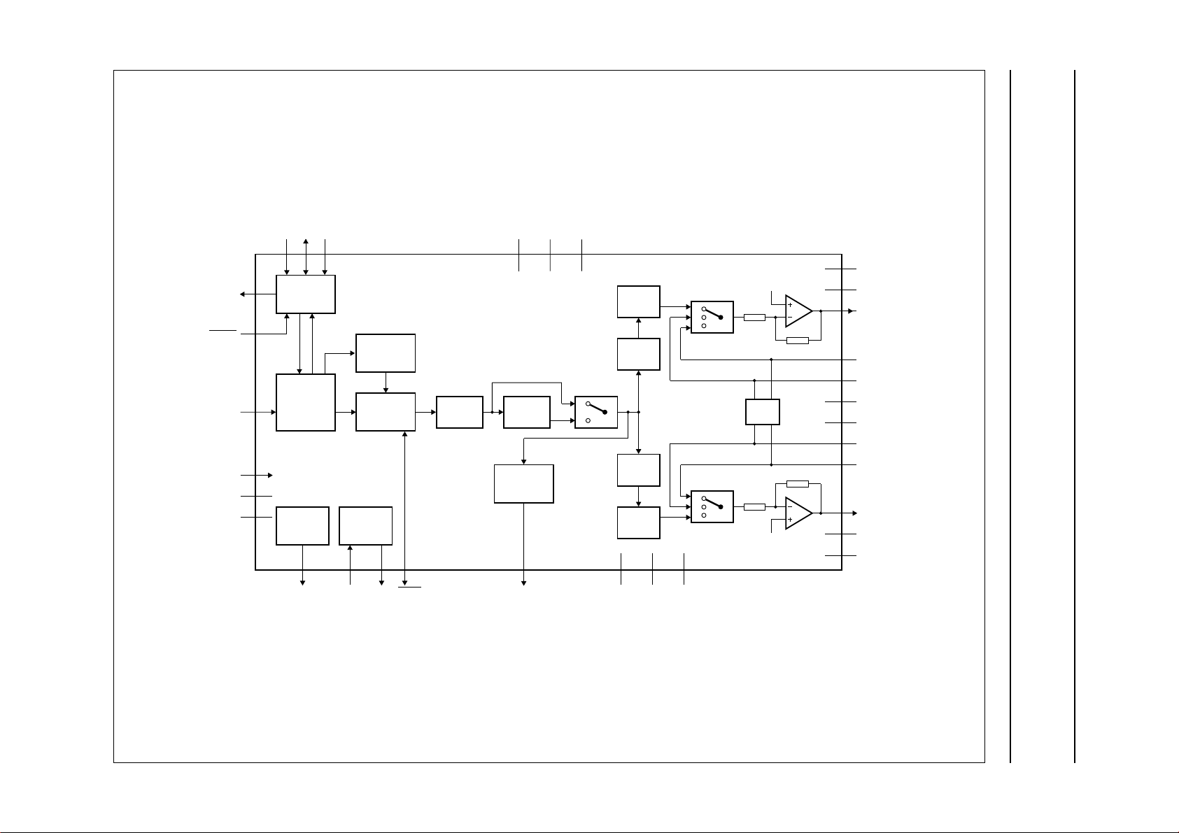
GENERAL DESCRIPTION
Performing all digital decoding functions for a NICAM 728
digital stereo sound system, the SAA7282 is a highly
integrated CMOS circuit which only requires a DQPSK
(Differential Quadrature Phase Shift Keying) demodulator
(TDA8732) and minimum external components to achieve
a full NICAM solution.
The device may also be interfaced to other DQPSK
demodulators.
QUICK REFERENCE DATA
SYMBOL PARAMETER MIN. TYP. MAX. UNIT
V
DD
I
DD
f
XTAL
T
amb
positive supply voltage 4.5 5.0 5.5 V
supply current − 50 100 mA
crystal frequency − 8.192 − MHz
operating ambient temperature 0 − 70 °C
ORDERING INFORMATION
EXTENDED TYPE
NUMBER
PINS PIN POSITION MATERIAL CODE
PACKAGE
SAA7282ZP 32 DIL32SHR plastic SOT232A
SAA7282GP 44 QFP plastic SOT205AG
Note
1. SAA7282ZP: 32-DIL32SHR; plastic (SOT232A); SOT232-1; 1996 November 28.
2. SAA7282GP: 44-QFP; plastic (SOT205AG); SOT205-1; 1996 November 28.
July 1993 2
(1)
(2)
This text is here in white to force landscape pages to be rotated correctly when browsing through the pdf in the Acrobat reader.This text is here in
_white to force landscape pages to be rotated correctly when browsing through the pdf in the Acrobat reader.This text is here inThis text is here in
white to force landscape pages to be rotated correctly when browsing through the pdf in the Acrobat reader. white to force landscape pages to be ...
July 1993 3
Philips Semiconductors Product specification
Terrestrial Digital Sound Decoder (TDSD2) SAA7282
PORT2
RESET
DATA
i.c.
V
DD
V
SS
5
2
32
26
27
29
SDA
ADSELSCL
4
6
3
2
I C
AUTO
MUTE
NICAM
728
DECODING
FREQ.
SYNTH.
13031
SWITCHING
XTAL
OSC
XIN XOUTPCLK
DIGITAL
7
MUTE
V
DAC
18
SAA7282ZP
FILTER DE-EMPH
DIGITAL
AUDIO
INTERFACE
28
DOBM V
CDL
INTL
20
19
1-BIT
DAC
NOISE
SHAPER
NOISE
SHAPER
1-BIT
DAC
17
REF
CDR
15
16
INTR
VRC
BIAS
VRC
25
24
23
21
22
10
11
13
14
12
MLB152
V
DDAL
V
SSAL
OPL
FML
EXTL
VRO
VRC
EXTR
FMR
OPR
8
V
DDAR
9
V
SSAR
handbook, full pagewidth
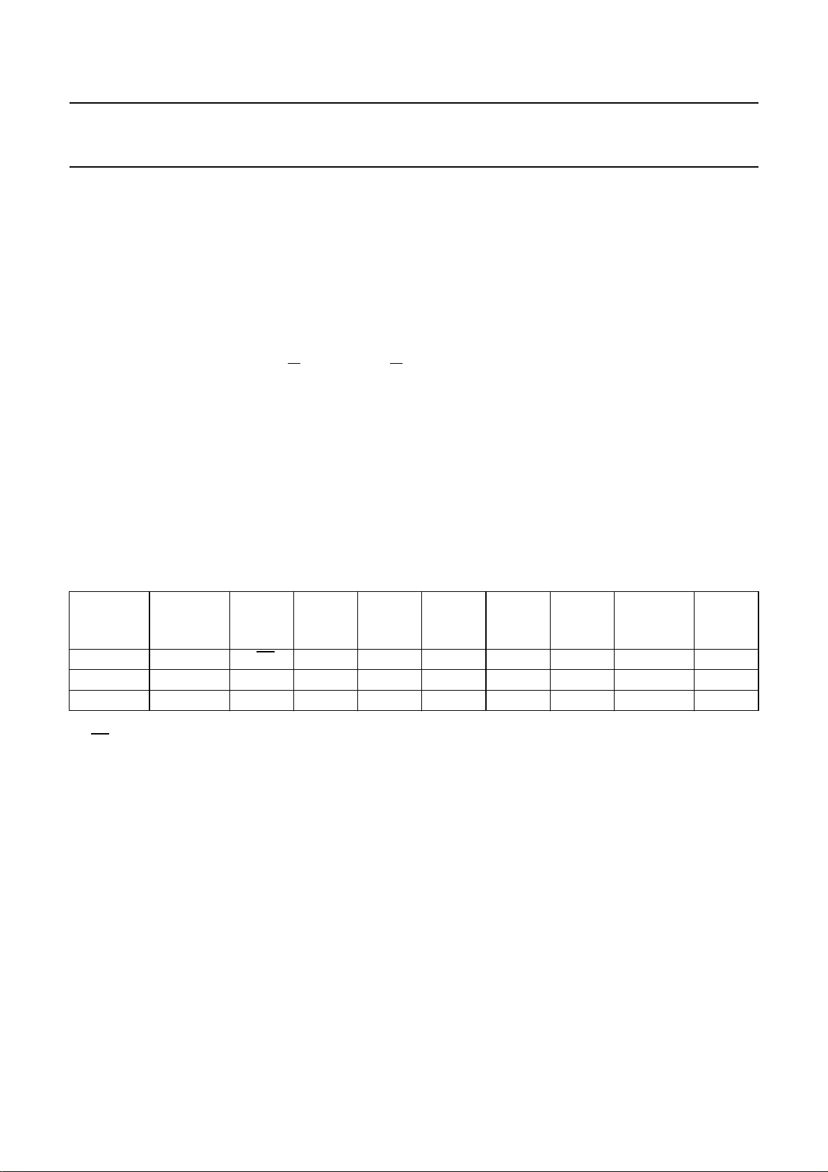
Fig.1 Block diagram; pin numbering for SOT232A.
Philips Semiconductors Product specification
Terrestrial Digital Sound Decoder (TDSD2) SAA7282
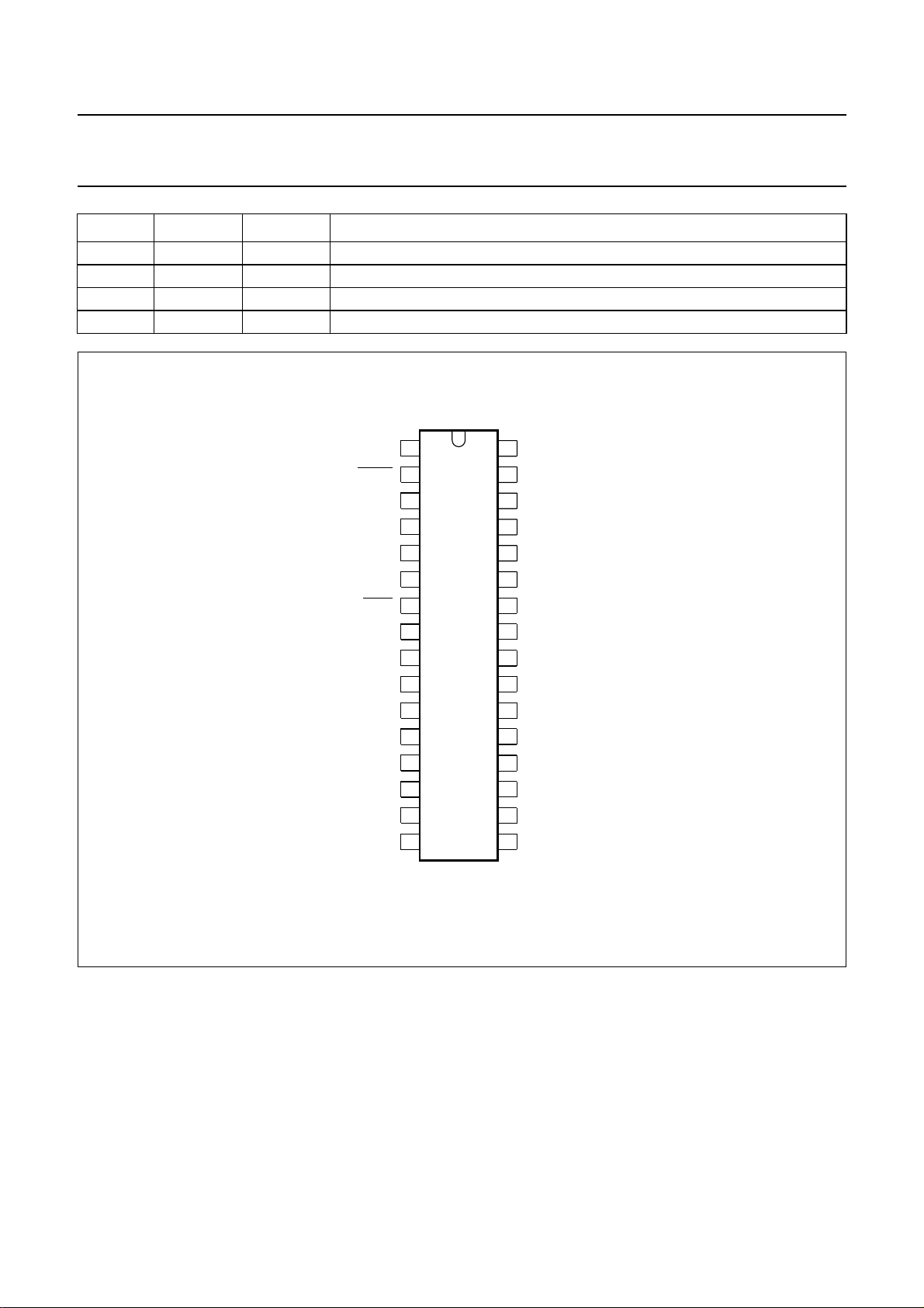
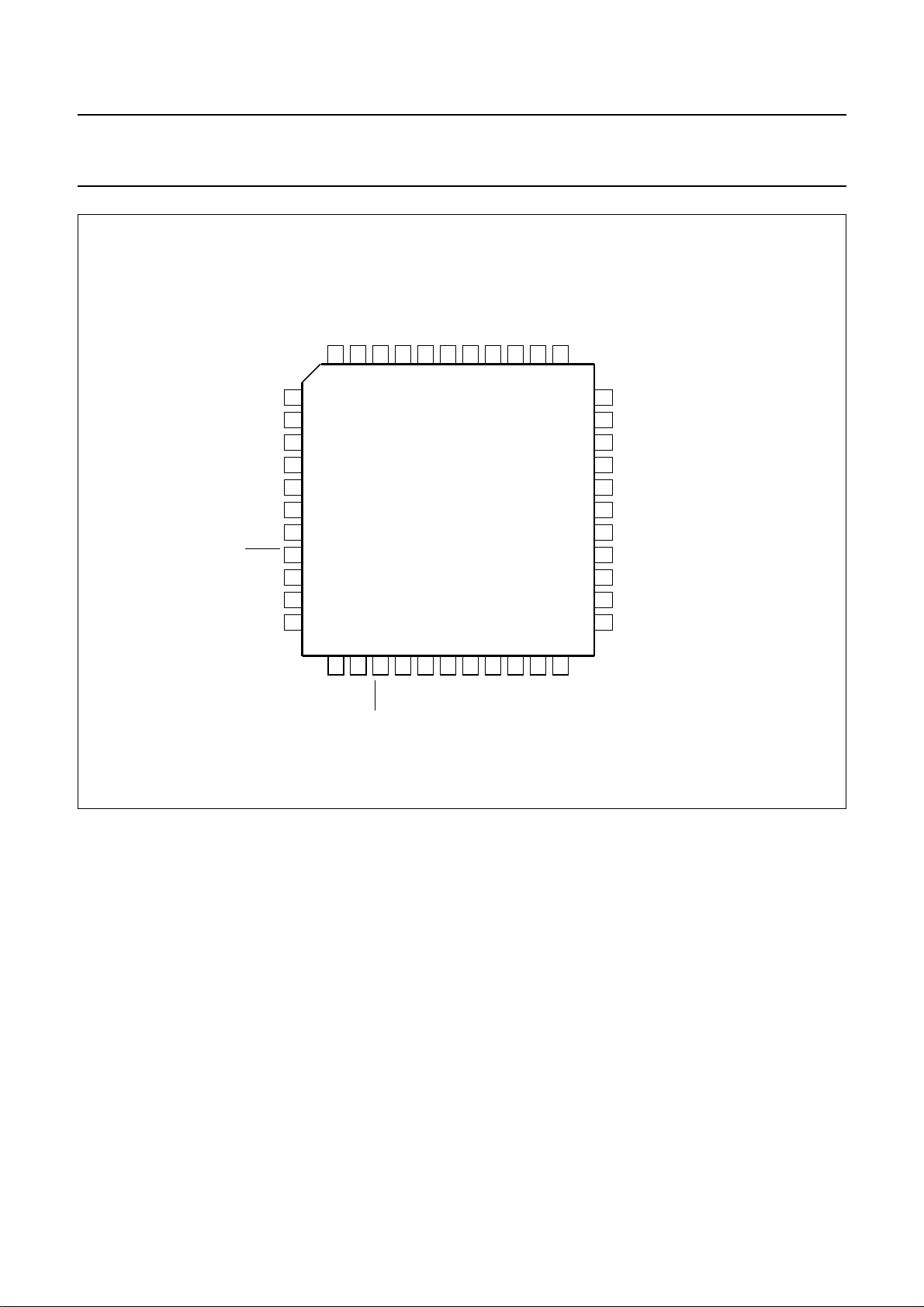
PINNING
SYMBOL SOT205AG SOT232A DESCRIPTION
DOBM 1 28 digital audio interface output
V
SS
n.c. 3 − not connected
XIN 4 30 crystal input at 256fs (8.192 MHz)
XOUT 5 31 crystal output at 256fs (8.192 MHz)
DATA 6 32 serial data input at 728 kbits/s from DQPSK demodulator
PCLK 7 1 output clock at 728 kHz to DQPSK demodulator
RESET 8 2 active LOW reset; used to set the device in a valid initial condition
SCL 9 3 clock input for I
SDA 10 4 data port for I
PORT2 11 5 output mirroring the I
n.c. 12 − not connected
ADSEL 13 6 I2C-bus slave address selection input; allows selection of one of two separate
MUTE 14 7 active LOW mute input; when set LOW, sets the digital data to zero and either
n.c. 15 to 17 − not connected
V
DDAR
V
SSAR
VRO 20 10 internal reference voltage buffer output
VRC 21 11 internal reference voltage buffer HIGH impedance node
n.c. 22 − not connected
OPR 23 12 analog output from the right audio channel
EXTR 24 13 external analog input to the right audio channel
FMR 25 14 FM sound input to the right audio channel
INTR 26 15 integrator output from the right audio channel
CDR 27 16 integrator connection to an external damping capacitor
n.c. 28 − not connected
V
REF
V
DAC
CDL 31 19 integrator connection to an external damping capacitor
INTL 32 20 integrator output from the left audio channel
FML 33 21 FM sound input to the left audio channel
EXTL 34 22 external analog input to the left audio channel
OPL 35 23 analog output from the left audio channel
n.c. 36 − not connected
V
SSAL
V
DDAL
2 29 ground connection for the digital section
2
C control bus
2
C control bus, input/open drain output
2
C control register bit PORT2
slave addresses, defaults to logic 1
silences the output or switches it to analog FM, depending on the status of
MUTEDEF (control bit in the I2C register) and RSSF; overridden by automute
(if automute is used, then MUTE is automatically pulled LOW)
18 8 analog supply voltage for the right audio channel
19 9 analog ground connection for the right audio channel
29 17 reference voltage input; 2.5 V (typical)
30 18 quiet VSS to DACs
37 24 analog ground connection for the left audio channel
38 25 analog supply voltage for the left audio channel
July 1993 4
Philips Semiconductors Product specification
Terrestrial Digital Sound Decoder (TDSD2) SAA7282
SYMBOL SOT205AG SOT232A DESCRIPTION
n.c. 39 to 41 − not connected
i.c. 42 26 internally connected; must be left open-circuit in application
n.c. 43 − not connected
V
DD
44 27 digital supply voltage
handbook, halfpage
PCLK
RESET
SCL
SDA
PORT2
ADSEL
MUTE
V
DDAR
V
SSAR
VRO
VRC
OPR
EXTR
FMR
INTR
CDR
1
2
3
4
5
6
7
8
SAA7282ZP
9
10
11
12
13
14
15
16
MLB153
32
31
30
29
28
27
26
25
24
23
22
21
20
19
18
17
DATA
XOUT
XIN
V
SS
DOBM
V
DD
i.c.
V
DDAL
V
SSAL
OPL
EXTL
FML
INTL
CDL
V
DAC
V
REF
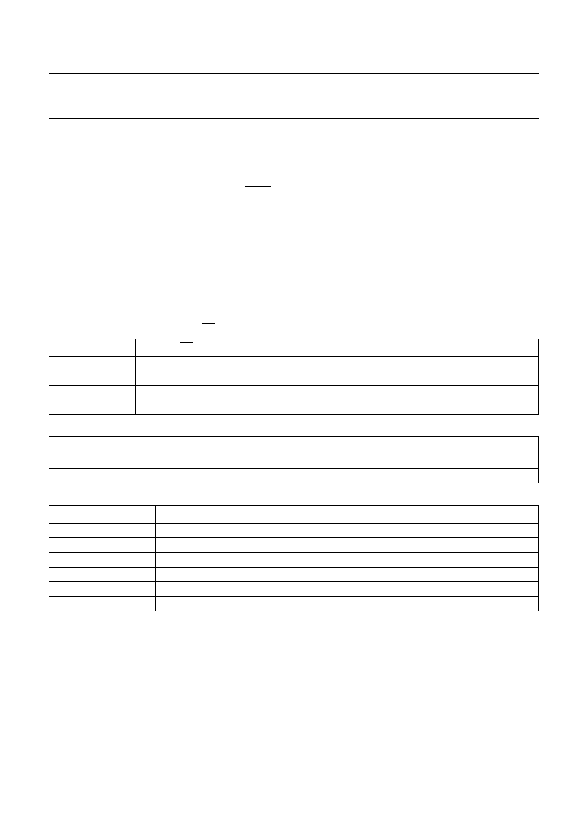
Fig.2 Pin configuration (SOT232A).
July 1993 5
Philips Semiconductors Product specification
Terrestrial Digital Sound Decoder (TDSD2) SAA7282
handbook, full pagewidth
DOBM
V
SS
n.c.
XIN
XOUT
DATA
PCLK
RESET
SCL
SDA
PORT2
DD
n.c.
V
44
43
1
2
3
4
5
6
7
8
9
10
11
12
13
n.c.
ADSEL
i.c.
42
14
MUTE
n.c.
n.c.
41
SAA7282GP
15
n.c.
n.c.
DDAL
SSAL
38
18
DDAR
V
37
19
SSAR
V
n.c.
36
20
VRO
OPL
35
21
VRC
EXTL
34
22
n.c.
33
32
31
30
29
28
27
26
25
24
23
MLB154
FML
INTL
CDL
V
DAC
V
REF
n.c.
CDR
INTR
FMR
EXTR
OPR
n.c.
V
40
39
16
17
n.c.
V
Fig.3 Pin configuration (SOT205AG).
July 1993 6
Philips Semiconductors Product specification
Terrestrial Digital Sound Decoder (TDSD2) SAA7282
I2C-BUS FORMATS
The SAA7282 contains an I2C-bus slave transceiver permitting a master device to:
• Read decoder status information derived from the transmitted digital audio signal
• Read an error count byte to determine the bit error rate for user mute purposes and to indicate quality of NICAM signal
• Read additional transmitted data bits. Their purpose has yet to be defined but accessibility is provided to allow future
services to be implemented in receiver software
• Write control codes to select the available analog switching configurations
• Write upper and lower error count limits for automatic muting function
The device slave address is A(7:1)(R/W) = 101101X(R/W). An ADSEL pin is provided to allow selection of one of two
different slave addresses via programmable address bit A1. (X = ADSEL logic level).
The SAA7282 does not acknowledge the I2C-bus general call address.
The slave receiver format is:
S SLAVE_ADDR.0 ACK SUB_ADDR ACK DATA BYTE ACK P
<−n bytes−>
Where S = start, ACK = acknowledge, P = stop.
Auto-increment of the sub-address is provided with wrap-around from 02 (HEX) to 00 (HEX).
The slave receiver data byte format, as a function of sub-address, is as shown in Table 1.
Table 1 Slave receiver data byte.
SUB-
ADDRESS
00 90 M1/M2 DMSEL SSWIT3 SSWIT2 SSWIT1 PORT2 MUTEDEF AMDIS
01 50 EMAX7 EMAX6 EMAX5 EMAX4 EMAX3 EMAX2 EMAX1 EMAX0
10 14 EMIN7 EMIN6 EMIN5 EMIN4 EMIN3 EMIN2 EMIN1 EMIN0
M1/
M2
This bit in conjunction with DMSEL bit, determines the output configuration in dual mono mode (see Table 2).
Power-on resets to logic 1.
DMSEL
This bit determines whether one or both of the dual mono signals are output (see Table 2). Power-on resets to logic 0.
PORT2
PORT2 controls a bit out, providing direct access to a dedicated output pin (PORT2) via the I2C-bus. See Table 3.
Power-on resets to logic 0.
RESET
VALUE
HEX
D7 D6 D5 D4 D3 D2 D1 D0
SSWIT3/2/1
These bits control the analog switching, selecting between the FM, external, and NICAM signals. With the NICAM source
the signals select whether the de-emphasis is performed and what gain is applied after the filtering and de-emphasis
stage. The signal states and their meaning are listed in Table 4. Power-on resets to 0/1/0.
July 1993 7
Philips Semiconductors Product specification
Terrestrial Digital Sound Decoder (TDSD2) SAA7282
AMOGMDIS
This bit enables and disables the automute function (which
is activated according to the error limit registers).
Power-on resets to enabled (i.e. AMDIS = logic 0). AMDIS
should be disabled for the user definable mute (MUTE) to
be used.
MUTEDEF
This defines the operation of the user definable MUTE pin
when it is pulled LOW externally. If MUTEDEF is HIGH and
RSSF = logic 1, the output of the device is switched to FM
input. If MUTEDEF is HIGH and RSSF = logic 0, or if
MUTEDEF is LOW, the output is muted. Power on resets
to LOW.
Table 2 Output as a function of M1/
DMSEL M1/
0 0 selects DIGITAL; L = M2, R = M2
0 1 selects DIGITAL; L = M1, R = M1
1 0 selects DIGITAL; L = M2, R = M1
1 1 selects DIGITAL; L = M1, R = M2
M2 and DMSEL.
M2 FUNCTION
ERROR LIMIT REGISTERS
UPPER ERROR LIMIT REGISTER
This defines the number of errors in 128 ms period which
will cause automute to switch IN. User definable, but
power on resets to 50 Hex.
LOWER ERROR LIMIT REGISTER
This defines the number of errors in 128 ms period which
will cause automute to switch OUT. User definable, but
power on resets to 14 Hex.
Table 3 Port 2 control.
PORT2 PIN OUTPUT STATE
0 LOW
1 HIGH
Table 4 SSWIT signal states and function.
SSWIT3 SSWIT2 SSWIT1 FUNCTION
0 0 0 NICAM source de-emphasis switched out, no gain
0 0 1 NICAM source de-emphasis switched in, no gain
0 1 0 NICAM source de-emphasis switched in, −6 dB gain; power-on reset state
0 1 1 NICAM source de-emphasis switched in, +12 dB gain
1 x 0 external inputs switched in, no change to previous de-emphasis/gain setting
1 x 1 FM inputs switched in, no change to previous de-emphasis/gain setting
Note
1. Where x = don’t care.
(1)
July 1993 8
 Loading...