

Page 1
REMstar Auto A-Flex
USER MANUAL
Page 2

© 2012 Koninklijke Philips Electronics N.V. All rights reserved.
Page 3

Table of Contents
Intended Use ........................................................................................................................................................... 2
Important ................................................................................................................................................................. 2
Warnings ..................................................................................................................................................................2
Cautions ................................................................................................................................................................... 3
Contraindications .................................................................................................................................................. 3
Symbol Key .............................................................................................................................................................. 4
System Contents .................................................................................................................................................... 5
System Overview ................................................................................................................................................... 5
Control Buttons ..................................................................................................................................................... 6
Available Therapy Modes ...................................................................................................................................... 6
Available Flex Comfort Features ........................................................................................................................6
Installing the Air Filters ......................................................................................................................................... 7
Connecting the Breathing Circuit ...................................................................................................................... 7
Where to Place the Device ................................................................................................................................. 7
Supplying AC Power to the Device ....................................................................................................................7
Navigating the Device Screens ............................................................................................................................8
Starting the Device ................................................................................................................................................ 8
Ramp Feature .......................................................................................................................................................... 9
Opti-Start Feature ................................................................................................................................................. 9
Mask Fit Check Feature ........................................................................................................................................ 9
Humidier Preheat ..............................................................................................................................................10
Flex Screen ............................................................................................................................................................ 10
Setup Screen .........................................................................................................................................................11
Info Screen .............................................................................................................................................................13
Device Alerts ........................................................................................................................................................15
Troubleshooting ...................................................................................................................................................18
Accessories ...........................................................................................................................................................19
Traveling with the System ..................................................................................................................................20
Cleaning the Device ............................................................................................................................................20
Cleaning or Replacing the Filters .....................................................................................................................20
Cleaning the Tubing ..............................................................................................................................................20
Service ....................................................................................................................................................................20
Specications ........................................................................................................................................................21
Disposal ..................................................................................................................................................................22
How to Contact Philips Respironics ...............................................................................................................22
EMC Information ................................................................................................................................................. 23
Limited Warranty ...................................................................................................................................Back Page
1User Manual
Page 4

CAUTION: U. S. federal law restricts this device to sale by or on the order of a physician.
Intended Use
The Philips Respironics REMstar Auto A-Flex system delivers positive airway pressure therapy for the treatment of Obstructive Sleep
Apnea in spontaneously breathing patients weighing over 30kg (66 lbs). It is for use in the home or hospital/institutional environment.
Important
The device is to be used only on the instruction of a licensed physician. The system can deliver CPAP therapy or Auto-CPAP
therapy. For enhanced pressure relief in CPAP mode, the device can also deliver C-Flex or C-Flex+. For enhanced pressure relief in
Auto mode, the device can deliver C-Flex or A-Flex. Your home care provider will make the correct pressure settings according to
your health care professional’s prescription.
When set in the Auto-CPAP therapy, the system will monitor your breathing as you sleep and automatically adjust the pressure to
meet your needs. When in CPAP therapy, the system will deliver a continuous, set pressure during the night.
Several accessories are available to make your OSA treatment with the REMstar Auto A-Flex system as convenient and comfortable
as possible. To ensure that you receive the safe, effective therapy prescribed for you, use only Philips Respironics accessories.
Warnings
A warning indicates the possibility of injury to the user or the operator.
• This manual serves as a reference. The instructions in this manual are not intended to supersede the health care professional’s
instructions regarding the use of the device.
• The operator should read and understand this entire manual before using the device.
• This device is not intended for life support.
• The device should be used only with masks and connectors recommended by Philips Respironics or with those recommended by the
health care professional or respiratory therapist. A mask should not be used unless the device is turned on and operating properly.
The exhalation port(s) associated with the mask should never be blocked. Explanation of the Warning: The device is intended
to be used with special masks or connectors that have exhalation ports to allow continuous ow of air out of the mask. When
the device is turned on and functioning properly, new air from the device ushes the exhaled air out through the mask exhalation
port. However, when the device is not operating, enough fresh air will not be provided through the mask, and exhaled air may be
rebreathed. Rebreathing of exhaled air for longer than several minutes can in some circumstances lead to suffocation.
• If you are using a full face mask (a mask covering both your mouth and your nose), the mask must be equipped with a safety (entrainment) valve.
• When using oxygen with this system, the oxygen supply must comply with local regulations for medical oxygen.
• Oxygen supports combustion. Oxygen should not be used while smoking or in the presence of an open ame.
• When using oxygen with this system, turn the device on before turning on the oxygen. Turn the oxygen off before turning the
device off. This will prevent oxygen accumulation in the device. Explanation of the Warning: When the device is not in
operation and the oxygen ow is left on, oxygen delivered into the tubing may accumulate within the device’s enclosure. Oxygen
accumulated in the device enclosure will create a risk of re.
• When using oxygen with this system, a Philips Respironics Pressure Valve must be placed in-line with the patient circuit between
the device and the oxygen source. The pressure valve helps prevent the backow of oxygen from the patient circuit into the device
when the unit is off. Failure to use the pressure valve could result in a re hazard.
• Do not connect the device to an unregulated or high pressure oxygen source.
• Do not use the device in the presence of a ammable anaesthetic mixture in combination with oxygen or air, or in the presence of nitrous oxide.
• Do not use the device near a source of toxic or harmful vapors.
• Do not use this device if the room temperature is warmer than 35° C (95° F). If the device is used at room temperatures warmer
than 35° C (95° F), the temperature of the airow may exceed 43° C (109° F). This could cause irritation or injury to your airway.
• Do not operate the device in direct sunlight or near a heating appliance because these conditions can increase the temperature of
the air coming out of the device.
• Contact your health care professional if symptoms of sleep apnea recur.
• If you notice any unexplained changes in the performance of this device, if it is making unusual or harsh sounds, if it has been
dropped or mishandled, if water is spilled into the enclosure, or if the enclosure is broken, disconnect the power cord and
discontinue use. Contact your home care provider.
• Repairs and adjustments must be performed by Philips Respironics-authorized service personnel only. Unauthorized service could
cause injury, invalidate the warranty, or result in costly damage.
• Periodically inspect electrical cords and cables for damage or signs of wear. Discontinue use and replace if damaged.
• To avoid electrical shock, always unplug the power cord from the wall outlet before cleaning the device. DO NOT immerse the
device in any uids.
2 User Manual
Page 5

• If the device is used by multiple persons (such as rental devices), a low-resistance, main ow bacteria lter should be installed in-
line between the device and the circuit tubing to prevent contamination.
• Be sure to route the power cord to the outlet in a way that will prevent the cord from being tripped over or interfered with by
chairs or other furniture.
• This device is activated when the power cord is connected.
• For safe operation when using a humidier, the humidier must always be positioned below the breathing circuit connection at
the mask and the air outlet on the device. The humidier must be level for proper operation.
Note: Please see the “Limited Warranty” section of this manual for information on warranty coverage.
Cautions
A Caution indicates the possibility of damage to the device.
• Medical electrical equipment needs special precautions regarding EMC and needs to be installed according to EMC information.
Contact your home care provider regarding EMC installation information.
• Mobile RF communications equipment can affect medical electrical equipment.
• Pins of connectors marked with the ESD warning symbol shall not be touched and connections shall not be made without
special precautions. Precautionary procedures include methods to prevent build-up of electrostatic charge (e.g., air conditioning,
humidication, conductive oor coverings, non-synthetic clothing), discharging one’s body to the frame of the equipment or
system or to earth. It is recommended that all individuals that will handle this device understand these precautionary procedures
at a minimum as part of their training.
• Before operating the device, ensure that the SD card cover is replaced whenever any of the accessories such as the Link Module
or Modem are not installed. Refer to the instructions that came with your accessory.
• Condensation may damage the device. If this device has been exposed to either very hot or very cold temperatures, allow it to
adjust to room temperature (operating temperature) before starting therapy. Do not operate the device outside of the operating
temperature range shown in the Specications.
• Do not use extension cords with this device.
• Do not place the device directly onto carpet, fabric, or other ammable materials.
• Do not place the device in or on any container that can collect or hold water.
• A properly installed, undamaged reusable foam inlet lter is required for proper operation.
• Tobacco smoke may cause tar build-up within the device, which may result in the device malfunctioning.
• Dirty inlet lters may cause high operating temperatures that may affect device performance. Regularly examine the inlet lters as
needed for integrity and cleanliness.
• Never install a wet lter into the device. You must ensure sufcient drying time for the cleaned lter.
• Always ensure that the DC power cord securely ts into your therapy device prior to use. Contact your home care provider or
Philips Respironics to determine if you have the appropriate DC cord for your specic therapy device.
• When DC power is obtained from a vehicle battery, the device should not be used while the vehicle’s engine is running. Damage
to the device may occur.
• Only use a Philips Respironics DC Power Cord and Battery Adapter Cable. Use of any other system may cause damage to the device.
Contraindications
When assessing the relative risks and benets of using this equipment, the clinician should understand that this device can deliver
pressures up to 20 cm H2O. In the event of certain fault conditions, a maximum pressure of 30 cm H2O is possible. Studies have
shown that the following pre-existing conditions may contraindicate the use of CPAP therapy for some patients:
• Bullous Lung Disease
• Pathologically Low Blood Pressure
• Bypassed Upper Airway
• Pneumothorax
• Pneumocephalus has been reported in a patient using nasal Continuous Positive Airway Pressure. Caution should be used when
prescribing CPAP for susceptible patients such as those with: cerebral spinal uid (CSF) leaks, abnormalities of the cribriform
plate, prior history of head trauma, and/or pneumocephalus. (Chest 1989; 96:1425-1426)
The use of positive airway pressure therapy may be temporarily contraindicated if you exhibit signs of a sinus or middle ear
infection. Not for use with patients whose upper airways are bypassed. Contact your health care professional if you have any
questions concerning your therapy.
3User Manual
Page 6
Symbol Key
The following symbols may appear on the device and power supply:
Sy m b o l Def i ni t io n
Consult accompanying instructions for use.
AC Power
DC Power
IP22
Drip Proof Equipment
Caution, consult accompanying documents.
ESD Warning symbol
Class II (Double Insulated)
Type BF Applied Part
For Indoor Use Only.
Do not disassemble.
For Airline Use. Complies with RTCA/DO-160F section 21, category M.
Separate collection for electrical and electronic equipment per EC Directive
2002/96/EC.
Use only with the standard 60W power supply 1091398.
(not for use with Heated Tubing)
Use only with the Heated Tubing compatible 80W power supply 1091399.
(can also be used when Heated Tubing is not in use)
4 User Manual
Page 7
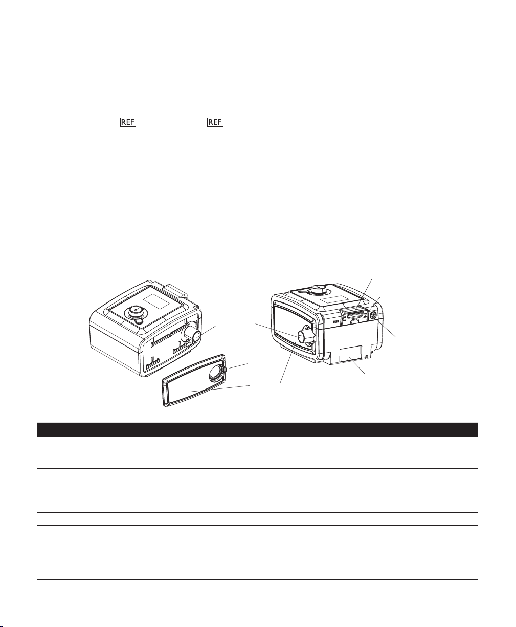
System Contents
Air Outlet Port
Power Inlet
Filter Area
SD Card (Accessory) Slot
Side Cover
T a b
SD Card Cover
Your REMstar Auto A-Flex system may include the following items:
• Device • SD card
• User manual • Side cover panel (optional)
• Carrying case • Reusable gray foam lter
• Flexible tubing • Disposable ultra-ne lter (optional)
• Power cord • Humidier (optional)
• Power supply (60W 1091398, or 80W 1091399)
Note: If any of these items are missing, contact your home care provider.
System Overview
The REMstar Auto A-Flex is a CPAP (Continuous Positive Airway Pressure) device designed for the treatment of
Obstructive Sleep Apnea (OSA). It can deliver CPAP therapy or Auto-CPAP therapy.
When prescribed for you, the device provides several special features to help make your therapy more comfortable.
The ramp function allows you to lower the pressure when you are trying to fall asleep. The air pressure will gradually
increase until your prescription pressure is reached. You also have the option of not using the ramp feature at all.
Additionally, the C-Flex, C-Flex+ and A-Flex comfort features provide you with pressure relief when you exhale
during therapy.
Several accessories are also available for use with your REMstar Auto A-Flex device. Contact your home care
provider to purchase any accessories not included with your system.
This gure illustrates some of the device features, described in the following table.
De v i c e fe a t u r e De S c r i p t i o n
Air Outlet Port
(conical, 22 mm)
SD Card (Accessory) Slot If applicable, insert the optional accessory SD card here.
SD Card Cover If applicable, the optional accessories such as a Link Module or Modem can be installed here.
Power Inlet Connect the power cord here.
Filter Area A reusable, gray foam lter must be placed in the lter area to screen out normal household
Side Cover (optional) If using a humidier with the device, this side cover can be easily removed with the release
Connect the 15 or 22 mm Philips Respironics exible tubing here.
Note: Heated Tubing should only be connected to the Air Outlet Port of the compatible
System One Heated Humidier and not to the Air Outlet Port of the therapy device.
Refer to the instructions supplied with the accessor y. When not using an accessory, this
cover must be in place on the device.
dust and pollens. A white ultra-ne lter can also be used for more complete ltration of very
ne particles.
tab before attaching the humidier. Refer to the humidier manual.
5User Manual
Page 8
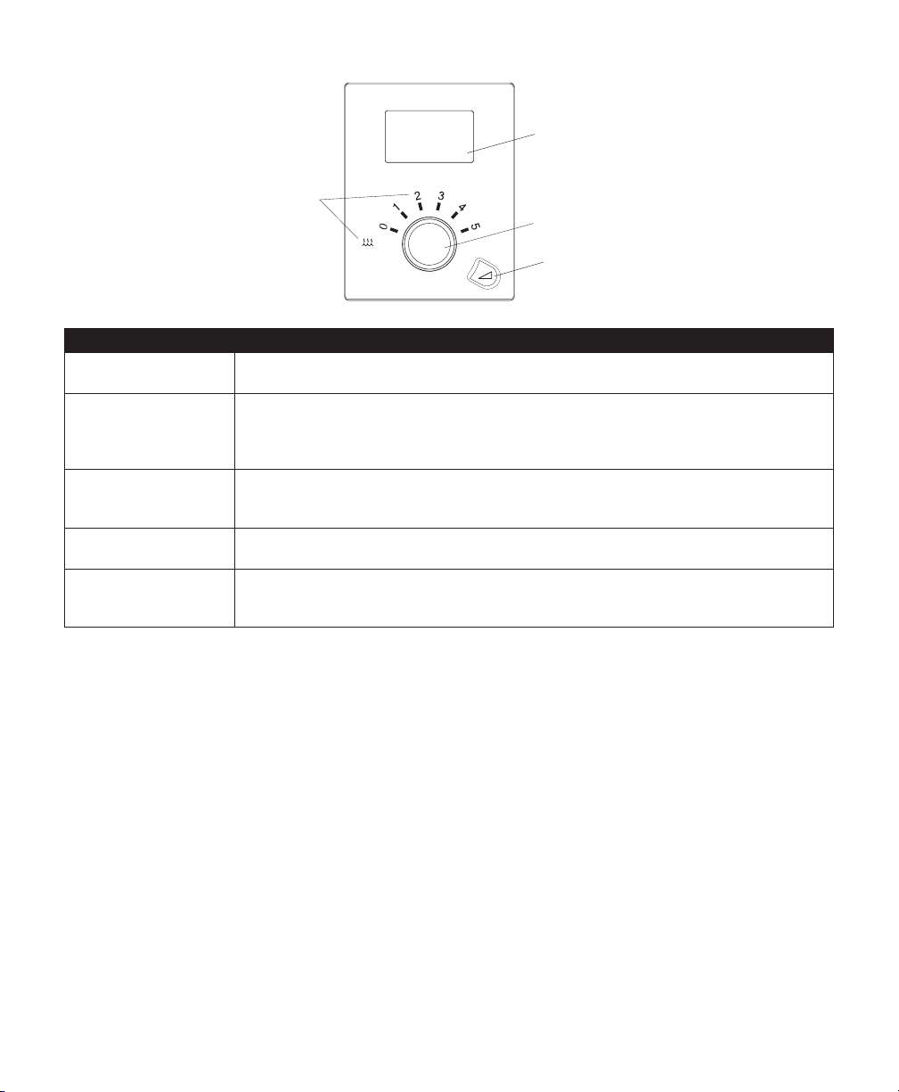
Control Buttons
LCD Display Screen
Ramp Button
Control Wheel/Push Button
Humidifier Icon &
Number Settings
This gure shows the primary control buttons on the device, described in the following table.
Fe a t u r e De s c r i p t i o n
Display Screen Shows therapy settings, patient data, and other messages. The startup screen is shown temporarily
Humidier Icon This Icon lights up (different colors) when the optional humidier and/or heated tube is attached
Humidier Numbers The humidier number settings are only visible when the humidier is attached and therapy is active.
Control Wheel/Push
Button
Ramp Button When the airow is on, this button allows you to activate or restart the ramp function. When
when the unit is rst powered.
and heat is being applied. White means classic humidication is selected. Blue means System One
humidication is selected. Orange means the heated tube is attached. Please refer to the humidier
user manual for more information.
You can use the control wheel to change the number settings for the humidier. When the heated
tube is being used with the humidier, these numbers will control the heated tube setting.
Turn the wheel to toggle between options on the screen. Press the wheel to choose an option.
Primary function is to turn airow on/off.
the airow is off, this button allows you to activate the Mask Fit Check. This button lights up when
therapy is active or during specic alerts.
Available Therapy Modes
The REMstar Auto A-Flex device offers the following therapy modes:
• CPAP – This mode delivers Continuous Positive Airway Pressure; CPAP maintains a constant level of pressure
• Auto-CPAP – This mode delivers CPAP therapy while automatically adjusting the pressure level to meet your needs.
• Auto-Trial – If available on your device, this mode delivers CPAP therapy while automatically adjusting the
• CPAP-Check – If available on your device, this mode delivers CPAP therapy while automatically adjusting the
Available Flex Comfort Features
The REMstar Auto A-Flex device offers the following optional Flex comfort features:
• C-Flex – Provides pressure relief upon exhalation to improve comfort based on your needs.
• A-Flex/C-Flex+ – Provides pressure relief taking place at the end of inhalation and at the start of exhalation to
6 User Manual
throughout the breathing cycle.
pressure level to meet your needs. Auto-Trial mode is limited to a specic number of days which is set by your
physician. Once the set number of days has elapsed, your device will automatically transition to CPAP-Check mode.
pressure level to meet your needs. Pressure adjustments while in CPAP-Check mode are more gradual than those
that occur in Auto-Trial mode and the amount of adjustment that can be made over time is limited.
improve comfort based on your needs. When providing Auto-CPAP or Auto-Trial therapy, this comfort feature is
called A-Flex. When providing CPAP or CPAP-Check therapy, this comfort feature is called C-Flex+.
Page 9

Installing the Air Filters
CAUTION: A properly installed, undamaged gray foam lter is required for proper operation.
The device uses a gray foam lter that is washable and reusable, and a white ultra-ne lter that is disposable. The
reusable lter screens out normal household dust and pollens, while the ultra-ne lter provides more complete
ltration of very ne particles. The gray reusable lter must be in place at all times when the device is operating. The
ultra-ne lter is recommended for people who are sensitive to tobacco smoke or other small particles.
The reusable gray foam lter is supplied with the device. A disposable ultra-ne lter may also be included. If your
lter is not already installed when you receive your device, you must at least install the reusable gray foam lter
before using the device. To install the lter(s):
1. If you are using the white disposable ultra-ne lter, insert it into the lter area rst, mesh-side facing in, towards the device.
2. Insert the required gray foam lter into the lter area after the ultra-ne lter.
Note: If you are not using the white disposable lter, simply insert the gray foam lter into the lter area.
Connecting the Breathing Circuit
To use the system, you will need the following accessories in order to assemble the recommended circuit:
• Philips Respironics interface (nasal mask or full face mask) with integrated exhalation port, or Philips Respironics
interface with a separate exhalation device (such as the Whisper Swivel II)
WARNING: If you are using a full face mask (a mask covering both your mouth and your nose), the mask must be
equipped with a safety (entrainment) valve.
• Philips Respironics 22 mm (or 15 mm) exible tubing, 1.83 m (6 ft.)
• Philips Respironics headgear (for the mask)
WARNING: If the device is used by multiple persons (such as rental devices), a low-resistance, main ow bacteria lter
should be installed in-line between the device and the circuit tubing to prevent contamination.
To connect your breathing circuit to the device, complete the following steps:
1. Connect the exible tubing to the air outlet on the side of the device.
Note: Make sure the Tubing type setting (15 or 22) matches the tubing you are using (Philips Respironics 15 or 22
mm tubing).
Note: Heated Tubing should only be connected to the Air Outlet Port of the compatible System One Heated
Humidier and not to the Air Outlet Port of the therapy device.
Note: If required, connect a bacteria lter to the device air outlet, and then connect the exible tubing to the
outlet of the bacteria lter.
Note: When using the bacteria lter, the device performance may be affected. However, the device will remain
functional and deliver therapy.
2. Connect the tubing to the mask. Refer to the instructions that came with your mask.
3. Attach the headgear to the mask if necessary. Refer to the instructions that came with your headgear.
Where to Place the Device
Place the device on a rm, at surface somewhere within easy reach of where you will use it at a level lower than your
sleeping position. Make sure the lter area on the back of the device is not blocked by bedding, curtains, or other items.
Air must ow freely around the device for the system to work properly. Make sure the device is away from any heating
or cooling equipment (e.g., forced air vents, radiators, air conditioners).
CAUTION: Do not place the device directly onto carpet, fabric, or other ammable materials.
CAUTION: Do not place the device in or on any container that can collect or hold water.
Supplying AC Power to the Device
CAUTION: Condensation may damage the device. If this device has been exposed to either very hot or very cold
temperatures, allow it to adjust to room temperature (operating temperature) before starting therapy. Do not
operate the device outside of the operating temperature range shown in the Specications.
WARNING: Be sure to route the power cord to the outlet in a way that will prevent the cord from being tripped
over or interfered with by chairs or other furniture.
WARNING: This device is activated when the power cord is connected.
IMPORTANT: If you are using your device with a humidier, refer to the instructions included with your
humidier for details on how to power the device and humidier.
7User Manual
Page 10

Complete the following steps to operate the device using AC power:
1. Plug the socket end of the AC power cord (included) into the power supply (also included).
IMPORTANT: When you are using Heated Tubing with the compatible System One Heated Humidier, you must
use the 80W power supply.
2. Plug the pronged end of the AC power cord into an electrical outlet that is not controlled by a wall switch.
3. Plug the power supply cord’s connector into the power inlet on the back of the device.
4. Ensure that all connections are secure.
IMPORTANT: To remove AC power, disconnect the power supply cord from the electrical outlet.
WARNING: Periodically inspect electrical cords and cables for damage or signs of wear. Discontinue use and
replace if damaged.
CAUTION: Do not use extension cords with this device.
Navigating the Device Screens
Turn the wheel to toggle between options and settings on the screen. Press the wheel to choose an option or setting
that is highlighted. If you choose “Back” on any screen, it will take you back to the previous screen.
Note: The screens shown throughout this manual are examples only. Actual screens may vary slightly. Examples are
for reference only.
Starting the Device
1. Supply power to the device.
2. The Home screen will appear, shown below.
Home Screen
Note: “Flex” shown above will display as the current Flex mode chosen by the provider.
Note: The SD card icon will display next to “Info”, if the SD card is inserted.
3. Put on your mask assembly.
Note: If you are having trouble with your mask, refer to the instructions supplied with the mask.
4. Turn the wheel to toggle between the four options. Highlight “Therapy”. Press the wheel to turn on the airow
and begin therapy. The Therapy screen will appear, which will show the current pressure setting being delivered
(example shown below).
Therapy Screen
Note: The SD card icon will display in the lower left corner if the SD card is inserted.
Note: If the Ramp feature is on, the Ramp icon will display in the lower right corner.
5. Make sure that no air is leaking from your mask into your eyes. If necessary, adjust the mask and headgear until the
air leak stops. See the instructions provided with your mask for more information.
Note: A small amount of mask leak is normal and acceptable. Correct large mask leaks or eye irritation from an air
leak as soon as possible.
6. If you are using the device in a bed with a headboard, try placing the tubing over the headboard. This may reduce
tension on the mask.
7. Press the wheel again to turn off therapy and return to the Home screen.
8 User Manual
Page 11

Ramp Feature
The device is equipped with an optional ramp feature that your home care provider can enable or disable. This
feature reduces the air pressure when you are trying to fall asleep and then gradually increases (ramps) the pressure
until your prescription setting is reached, allowing you to fall asleep more comfortably.
If ramp is enabled on your device, after you turn on the airow, press the RAMP ( ) button on the top of the
device. You can use the RAMP button as often as you wish during the night.
Note: If the Ramp feature is on, the Ramp icon ( ) will display in the lower right corner of the Therapy screen.
Note: If the airow is off and you press the RAMP button, the mask t check feature will start if it is enabled by
your provider.
Note: If the device is in Auto-CPAP therapy mode and Ramp is disabled, pressing the RAMP button will reduce the
air pressure and restart Auto-CPAP therapy at the Auto minimum pressure.
Opti-Start Feature
This feature allows your device to use your most recent sleep performance as an input to your next Auto-CPAP
therapy session. The goal is to start your therapy closer to your adjusted pressure. This optional feature can be
enabled or disabled by your home care provider.
The therapy screen will display “Opti-Start” below the starting therapy pressure, example shown here.
Therapy Screen with Opti-Start
“Opti-Start” will only appear on the therapy screen at the start of therapy. It will only stay on the screen for as long as
the device is delivering the starting therapy pressure. As soon as the pressure changes, “Opti-Start” will disappear.
Note: Opti-Start is only available if the device is in Auto-CPAP therapy mode.
Mask Fit Check Feature
The optional mask t check feature can be enabled or disabled by your home care provider. This feature allows you
to check the t of your mask prior to starting therapy. This is done by measuring the amount of leak.
Put on your mask assembly. If mask t check is enabled, before you turn on the airow, press the RAMP ( )
button on the top of the device. Airow will start and the mask t check screen will appear, shown below.
Mask Fit Check
The device will deliver a test pressure while the screen will count down 40 seconds. After the test, normal therapy
will start and the screen will either display a checkmark ( ) or an . The shows that the leak found allows for
optimal performance of the device. The shows that the leak may affect device performance, however, the device
will remain functional and deliver therapy.
Note: If you choose to try to improve your mask t, you can stop therapy, adjust the t of your mask, and rerun the
Mask Fit Check. Please refer to the instructions that came with your mask and headgear for the proper tting procedure.
Note: Mask Fit Check is only available if the device is in Auto-CPAP or Auto-Trial therapy mode.
Note: If Split night is enabled, Mask Fit Check will be disabled.
9User Manual
Page 12

Humidier Preheat
When using a humidier, the device can preheat the water tank for up to 30 minutes prior to starting therapy.
In order to activate the preheat mode, the blower must be “off” and a humidier must be attached. From the device
Home screen, highlight “Therapy”, then press and hold down the control wheel for 5 seconds. You will hear a single
beep and the device will now be in preheat mode. The humidier icon ( ) will illuminate during this time.
During the 30 minute preheat, you will still be able to use the control wheel to select other menu options from the
Home screen. If you press the wheel while “Therapy” is highlighted on the Home screen, preheat mode will end and
the blower will turn “on” to begin therapy. The humidier number selected in the setup menu (0, 1, 2, 3, 4, or 5) will
now take effect.
Flex Screen
From the Home screen, highlight “Flex” and press the wheel. The following Flex screen will appear.
Flex Screen
Note: “Flex” shown above will display as the current Flex mode chosen by the provider.
• Flex - The Flex comfort feature allows you to adjust the level of air pressure relief that you feel when you exhale
during therapy. Your home care provider can enable or disable this feature. When your provider enables Flex, a
level will already be set for you on the device. If this is not comfortable, you can increase or decrease the setting.
The setting of “1” provides a small amount of pressure relief, with higher numbers providing additional relief. If the
provider has disabled this feature, this setting will not display.
Note: This same setting is also available under the “Setup” screen.
• Flex demo - The Flex setting allows you to set the Flex level prior to beginning therapy. The Flex demo setting
allows you to try out the different Flex settings in real time. After a period of time of inactivity, the device will
stop therapy and will use the last Flex demo setting as the new Flex setting for your device. When therapy is again
started from the Home screen, the device will operate using the new Flex setting.
10 User Manual
Page 13

Setup Screen
Back
Flex 1 2 3
Heated Tube humidication on o
SYSTEM ONE humidication on o
Humidier 0 1 2 3 4 5
Humidity level 1 2 3
Tube temperature 0 1 2 3 4 5
Ramp time 0:00 - 0:45
Ramp start 4.0 - (auto min)or(CPA P pres)
Tubing type 15 22 15H
SYSTEM ONE resistance X1 X2 X3 X4 X5
Auto on on o
Auto o on o
Mask alert on o
Humidier LED Backlight on o
Silent mode on o
Language EN ES
Back
Setup
From the Home screen, highlight “Setup” and press the wheel. The following Setup screen will appear. The user can
change settings in the Setup menu. All settings are shown here. Your display will vary based on device settings.
Setup Screen
Note: The screen will only show a few lines at a time. As you rotate the wheel to toggle over different options
the screen will slide up and down accordingly. If the text is too long to completely t on the screen, it will scroll
horizontally across the screen when highlighted.
• Flex - This displays the Flex level set by your home care provider. Your home care provider will either enable or
disable Flex. If Flex is enabled and the setting is not comfortable, you can increase or decrease this setting. If your
provider has disabled Flex, you will not see this setting.
Note: This same setting is also available under the “Flex” screen.
• Heated Tube humidication - This setting will only display if you are using the heated tube. You can enable or
disable this feature.
• SYSTEM ONE humidication - System One humidity control maintains a consistent mask humidity by
monitoring and adjusting for changes in room temperature and room humidity. You can enable or disable this
feature. If the System One humidity control has been disabled, the classic style of basic temperature controlled
heated humidication will be used. This will only display if the humidier is attached.
• Humidier - This setting allows you to choose the desired humidity setting: 0, 1, 2, 3, 4 or 5. If the System One
humidity control has been disabled, the classic style of basic temperature controlled heated humidication will be
used and the display will show: 0, C1, C2, C3, C4 or C5 for these settings. This will only display if the humidier is
attached. Please refer to the humidier manual if using a humidier.
Note: When not using Heated Tubing, the control wheel can also be used to change this setting.
IMPORTANT: The ideal humidier setting depends on room temperature and humidity. Initially, a setting of 2 is
recommended. You can adjust this at any time.
• Humidity level - This setting will only display if you are using the heated tube. This setting allows you to choose
the desired humidity setting for the humidier: 1, 2 or 3. This setting can only be changed from the Setup screen.
• Tube temperature - This setting will only display if you are using the heated tube. This setting allows you to
choose the desired temperature for the heated tube: 0, 1, 2, 3, 4 or 5. If you choose zero (0), this will turn off both
the humidier and the heated tube.
Note: When using Heated Tubing, the control wheel can also be used to change this setting.
11User Manual
Page 14

• Ramp time - This enables you to modify the Ramp time setting in 5 minute increments. The range for this setting
is 0 to 45 minutes
• Ramp Start - This displays the ramp starting pressure. You can increase or decrease the ramp starting pressure
in 0.5 cm H2O increments. This is only available if Ramp time has been set to >0 and therapy pressure >4 cm H2O.
This will not display if your provider enabled Split night on your device.
• Tubing Type - This setting allows you to select the correct size diameter tubing that you are using with the
device. You can choose either (22) for the Philips Respironics 22 mm tubing, or (15) for the Philips Respironics 15
mm tubing. When using Heated Tubing, the device will automatically change this setting to the appropriate tubing
type (15H) and you will not be able to change it.
Note: If the Heated Tubing is removed, the device will default back to the previous tubing type setting.
• SYSTEM ONE resistance ( ) - This setting allows you to adjust the level of air pressure relief based on
the specic Philips Respironics mask. Each Philips Respironics mask may have a “System One” resistance control
setting. Contact your home care provider if you cannot nd this resistance setting for your mask. If your provider
has locked the resistance setting into place, you can view the setting but cannot change it, and the screen will
display a lock symbol. If your provider has disabled resistance, you will not see this setting.
• Auto on - You can enable this feature if you want the device to automatically turn the airow on whenever you
apply the interface (mask) to your airway. You can also disable this feature.
• Auto off - You can enable this feature if you want the device to automatically turn the airow off whenever you
remove the interface (mask) from your airway. You can also disable this feature.
• Mask alert - You can enable or disable the mask alert setting. If this feature is enabled, when a signicant mask
leak is detected, the mask alert will appear on the display screen and an audible alert will sound. Refer to the
Device Alerts section for more information about the mask alert.
• Humidier LED backlight (Ramp Backlight) - You can enable or disable the LED backlight for the humidier
number settings and Ramp button on the device.
Note: If the Humidier is not attached, this feature will display “Ramp Backlight” and control the LED backlight for
the Ramp button only.
Note: If the Humidier LED Backlight is enabled or disabled, the humidier icon will always remain on (if
humidier is attached and heat is being applied), but will dim after 30 seconds of inactivity.
• Silent mode - You can disable this feature if you want the device to emit an audible indicator (beep) during the
following device operations: power on, therapy start, therapy stop, mask t check, and humidier preheat mode.
The device defaults to the Silent mode being enabled, meaning the device does not emit a beep during these
operations.
• Language - This feature allows you to choose which language to display on the interface. You can choose English
(EN) or Spanish (ES).
12 User Manual
Page 15

Info Screen
Back
Status
Phone-in
Compliance VIC
Therapy hours
Days > 4
Large leak
AHI
Periodic breathing
90% pressure
Auto-Tr ial
CPAP-Check
Humidier
Back
Info
From the Home screen, highlight “Info” and press the wheel. The following Info screen will appear. The user cannot
change settings in the Info menu.
Note: These screens are only for reference. Your home care provider may periodically ask you for this information.
Info Screen
Note: The screen will only show a few lines at a time. As you rotate the wheel to toggle over different options the
screen will slide up and down accordingly.
• Status - This displays information sent from a peripheral (SD card , modem , etc.). If two peripherals are
attached, two lines will appear with corresponding icons.
Note: This will not display if no peripherals are being used.
• Phone-in - This screen displays the total therapy hours for the device, the total blower hours, and the total
number of days used when the sessions were greater than 4 hours since the device was last reset by the home care
provider. This screen also displays a compliance check number used by your home care provider to validate that
the data provided by you is the data taken from this screen. This setting only appears if your provider has enabled
this feature.
• Compliance VIC (Visual Inspection Check) - This screen displays the start day and the total number of days
used when the sessions were greater than 4 hours. This screen also displays a check code number used by your
home care provider to validate that the data provided by you is the data taken from this screen. This setting only
appears if your provider has enabled this feature.
• Therapy hours - The device is capable of recognizing the difference between the time the patient is actually
receiving therapy and the time when the blower is simply running. This screen displays the amount of time the
patient is actually receiving therapy on the device for the most recent 1 day time frame. It also displays the
average amount of time the patient is actually receiving therapy on the device over a 7 day and a 30 day time frame
(provided the device has at least 7 or 30 days of data respectively). If the device has only 5 days of data to use for
the calculation, the 5 day average value will be seen under the 7 day display.
• Days > 4 - This screen displays the cumulative number of device therapy sessions that exceeded 4 hours over a 1
day, a 7 day, and a 30 day time frame.
13User Manual
Page 16

• Large leak - During any given night, the device recognizes the percentage of time the patient was experiencing
what it deemed to be a large leak. Large leak is dened as the level of leak that is so large, it is no longer possible
to determine respiratory events with statistical accuracy. This screen displays the nightly value of percentage of time
in large leak for the most recent 1 day time frame. It also displays the average of these individual nightly values of
percentage of time in large leak over a 7 day and a 30 day time frame (provided the device has at least 7 or 30 days
of data respectively). If the device has only 5 days of data to use for the calculation, the 5 day average value will be
seen under the 7 day display. If you see a large increase in the percent of time in large leak indicated here, contact
your home care provider for assistance. This screen only displays if your home care provider has enabled it.
• AHI - The device accumulates individual Apnea/Hypopnea indices (AHI) for each session the patient used the
device. This screen displays the nightly AHI value for the most recent 1 day time frame. It also displays the average
of these individual nightly AHI values over a 7 day and a 30 day time frame (provided the device has at least 7 or
30 days of data respectively). If the device has only 5 days of data to use for the calculation, the 5 day average value
will be seen under the 7 day display. This screen only displays if your home care provider has enabled it.
• Periodic Breathing - During any given night, the device recognizes the percentage of time the patient was
experiencing periodic breathing. This screen displays the nightly value of periodic breathing for the most recent
1 day time frame. It also displays the average of these individual nightly values of periodic breathing over a 7 day
and a 30 day time frame (provided the device has at least 7 or 30 days of data respectively). If the device has only
5 days of data to use for the calculation, the 5 day average value will be seen under the 7 day display. If you see
a large increase in the percent of time in periodic breathing indicated here, contact your home care provider for
assistance. This screen only displays if your home care provider has enabled it.
• 90% Pressure - During any given night, the device recognizes the 90% Pressure achieved by the Auto Algorithm.
90% Pressure is dened as the pressure at which the device spent 90% of the session time at or below. For
example, if the device recognized airow for 10 hours, and 9 hours were spent at or below 11 cm H2O, and 1
hour was spent above 11 cm H2O, then the 90% Pressure would be 11 cm H2O. This screen displays the nightly
value of 90% Pressure for the most recent 1 day time frame. It also displays the average of these individual nightly
values of 90% Pressure over a 7 day and a 30 day time frame (provided the device has at least 7 or 30 days of
data respectively). If the device has only 5 days of data to use for the calculation, the 5 day average value will be
seen under the 7 day display. This screen only displays if the device is in Auto-CPAP or Auto-Trial therapy mode.
• Auto-Trial - If Auto-Trial mode is available, this screen displays Days: xx/xx (where xx/xx is the number of
accumulated trial days / number of selected trial days). This screen only displays if your home care provider has
enabled Auto-Trial.
• CPAP-Check - If CPAP-Check mode is available, this screen will either display XX.X (where XX.X is the CPAP-
Check Pressure) or 90%(XX.X) (where XX.X is the 90% pressure level, if already established by Auto-Trial mode).
This screen will also display xx/30 (where xx is the number of Hours Used / 30 Hours). This screen only displays if your
home care provider has enabled CPAP-Check.
• Humidier - This screen will display 3 settings: power supply (either the 60W or 80W), tubing type, and either
humidier or tube temperature setting (if using).
14 User Manual
Page 17

Device Alerts
• High Priority: These alerts require immediate operator response. The alert signal consists of a high priority sound,
which is a continuous two-beep pattern (indicated in the following table as: • • • •). Additionally, the backlights on
the buttons will provide a high priority ashing pattern consisting of a continuous, bright-to-off, two-ash pattern
(indicated in the following table as: ◊◊ ◊◊).
• Medium Priority: These alerts require prompt operator response. The alert signal consists of a medium priority
sound, which is a continuous one-beep pattern (indicated in the following table as: • •). Additionally, the backlights
on the buttons will provide a medium priority ashing pattern consisting of a continuous, bright-to-dim, one-ash
pattern (indicated in the following table as: ◊ ◊).
Alert Summary Table: The following table summarizes the alerts.
al e r t au D i b l e
Service Required
Mask Alert
Auto Off single beep Screen displays
Humidier Alert none
Power Supply Alert none
in D i c a t o r
• • • • ◊◊ ◊◊
• • ◊ ◊
Vi s u a l
in D i c a t o r
Screen displays
“Service required”.
Screen displays
“Mask alert”.
“Auto off”.
◊ ◊
Humidier LED
icon will ash on
the device.
◊ ◊
Humidier LED
icon will ash
orange for 30
seconds then
return to solid
blue.
De V i c e a c t i o n po s s i b l e
The device enters
the “Safe state” in
which the device
power remains on,
but the airow is
disabled.
Alert present until
action is taken.
The airow shuts
off and the device
enters the Standby
state approximately
45-60 seconds
after detection.
Alert present for
30 seconds or until
user acknowledges.
Only displayed when
both the humidier
and therapy is on.
Only displayed when
incorrect power
supply is used with
the heated tube.
ca u s e
Device failure. Press either the wheel or ramp
The breathing
circuit is
disconnected
or there is a
large air leak.
The mask has
been removed.
Humidier
failure.
Using wrong
power supply.
pa t i e n t ac t i o n
button to silence the alert.
Remove the power supply cord
from the device to remove power.
Plug the cord back into the
device’s power inlet to restore
power. If the alert continues to
occur, contact your home care
provider.
Turn off airow. Check your
breathing circuit connections
and reconnect the tubing if it has
come loose. Make sure your
mask is on properly before you
restart the airow. If the alert
continues to occur, contact your
home care provider to have your
mask checked. You may need a
mask retting.
Put your mask back on and turn
the airow on to resume therapy.
Alert is present for 12 minutes or
until the condition is xed. Turn
off airow and reconnect the
humidier to the device according
to the humidier instructions.
If the alert continues to occur,
contact your home care provider.
Alert is present for 30 seconds
or until the condition is xed. You
must use the 80W power supply
when using the heated tube. If the
alert continues to occur, contact
your home care provider.
15User Manual
Page 18

al e r t au D i b l e
in D i c a t o r
Heated Tube Error none Humidier LED
Vi s u a l
in D i c a t o r
icon will slowly
ash orange for
30 seconds then
return to solid
blue.
De V i c e a c t i o n po s s i b l e
Alert present for
30 seconds or until
condition is xed.
ca u s e
Tubing may be
overheating or
malfunctioning.
pa t i e n t ac t i o n
Alert is present for 30 seconds or
until the condition is xed. Turn off
airow and reconnect the heated
tubing to the humidier according
to the humidier instructions.
If the alert continues to occur,
contact your home care provider.
Instant Message single beep Home care
Patient Reminder single beep Screen displays
SD Card: Prescription
Accepted
SD Card: Prescription
Rejected
SD Card: Inserted
Incorrectly
SD Card: Full
SD Card: Remove single beep
single beep Screen displays
single beep
• • ◊ ◊
• • ◊ ◊
provider will
supply text to be
displayed.
message from the
provider.
“SD card inserted,
prescription
accepted”.
◊ ◊
Screen displays
“SD card inserted,
prescription
rejected”.
Screen displays
“SD card inserted
incorrectly”.
Screen displays
“SD card full”.
◊ ◊
Screen displays
“SD card
removed”.
Only displayed when
therapy is off.
Only displayed when
therapy transitions
from on to off.
Alert present for
6 minutes or until
user acknowledges.
Alert present for
30 seconds or until
user acknowledges.
Alert present for
30 seconds or until
user acknowledges.
Alert present until
action is taken.
Alert present until
action is taken.
Alert present for
30 seconds or until
user acknowledges.
Message from
the provider.
Message from
the provider.
n/a Card status can be checked in
Prescription
missing or
incorrect.
SD card
inserted
incorrectly.
SD card is full. Alert is present until card is
SD card has
been removed.
Your home care provider may
send an instant message. Contact
your home care provider with any
questions.
Your home care provider may
set a patient reminder scheduled
to pop up at a particular time to
remind you to replace your mask,
change your lters, etc. “Check
your mask, a new one may be
available. Call your provider.” is the
default message. The provider may
change the message.
Status menu.
Contact your home care provider
for correct prescription.
Alert is present until card is
removed. Remove SD card and
reinsert correctly. If the alert
continues to occur, contact your
home care provider.
removed. Remove SD card and
replace. Card status can be
checked in the Status menu from
the Info screen. Refer to “Using
the SD Card” in the “Accessories”
section of this manual for more
information about the SD card.
No action needed.
SD Card: Data
Activity
16 User Manual
single beep Screen displays
“Data activity: Do
not remove card”.
Alert present for
30 seconds or until
user acknowledges
or data activity
complete.
n/a No action needed. Refer to “Using
the SD Card” in the “Accessories”
section of this manual for more
information about the SD card.
Page 19

al e r t au D i b l e
SD Card: Corrupt
in D i c a t o r
• • ◊ ◊
Screen displays
“Corrupt card
inserted reformat
card?”.
Vi s u a l
in D i c a t o r
De V i c e a c t i o n po s s i b l e
Alert present until
action is taken.
ca u s e
A problem
exists with the
SD card. The
data may be
corrupted.
pa t i e n t ac t i o n
Choose “yes” to reformat
the card. Screen displays
“Reformatting... do not remove
card”.
If you choose no, the alert will
disappear and the card will
not be reformatted. Note: Any
information on the card will be
lost when reformatted. Contact
your home care provider with any
questions.
SD Card: Remove
and Reinsert
Modem: Making Call single beep Modem will
Modem: Unsuccessful
Call
• • ◊ ◊
Screen displays
“SD card error:
remove and
reinsert”.
display its own
icon on the device.
Refer to modem
instruction manual.
single beep
Modem will
display its own
icon on the device.
Refer to modem
instruction manual.
◊ ◊
Alert present until
action is taken.
Alert present for 30
seconds after call
sequence or until
user acknowledges.
Alert present for
30 seconds or until
user acknowledges.
Device cannot
read the
SD card. A
problem may
exist with the
SD card or
it is inserted
incorrectly.
Refer to
modem
instruction
manual.
Refer to
modem
instruction
manual.
Remove SD card and reinsert.
If the alert continues to occur,
replace with another card or
contact your home care provider.
If modem is making call while
therapy is active, alert for call
sequence is not displayed.
No action needed.
17User Manual
Page 20

Troubleshooting
The table below lists some of the problems you may experience with your device and possible solutions to those problems.
pr o b l e m Wh y it ha p p e n e D Wh a t t o Do
Nothing happens
when you apply
power to the device.
The backlights on the
buttons do not light.
The airow does not
turn on.
The device’s display is
erratic.
The Ramp feature
does not work when
you press the Ramp
button.
The airow is much
warmer than usual.
The airow pressure
feels too high or too
low.
Tube Temperature is
turned on in “Setup”
screen but Heated
Tubing is not warm.
Tube Temperature is
turned on in “Setup”
screen but Humidier
LED does not stay
orange (changes to
blue).
There’s no power
at the outlet or the
device is unplugged.
There may be a
problem with the
blower.
The device has
been dropped or
mishandled, or
the device is in
an area with high
Electromagnetic
Interference (EMI)
emissions.
Your home care
provider did not
prescribe Ramp for
you, or your therapy
pressure is already
set to the minimum
setting.
The air lters may
be dirty.
The device may be
operating in direct
sunlight or near a
heater.
The Tubing type
setting may be
incorrect.
Incorrect power
supply is being used
(60W is used instead
of 80W).
Heated Tubing is
attached incorrectly
or damaged.
If you are using AC power, check the outlet and verify that the device is properly
plugged in. Make sure there is power available at the outlet. Make sure the AC power
cord is connected correctly to the power supply and the power supply cord is securely
connected to the device’s power inlet. If the problem continues to occur, contact your
home care provider. Return both the device and power supply to your provider, so they
can determine if the problem is with the device or power supply.
If you are using DC power, make sure your DC power cord and battery adaptor cable
connections are secure. Check your battery. It may need recharged or replaced. If the
problem persists, check the DC cord’s fuse following the instructions supplied with your
DC cord. The fuse may need to be replaced. If the problem still occurs, contact your
home care provider.
Make sure the device is powered correctly. Make sure “Therapy” is highlighted when
pressing the control wheel to start airow. If the airow does not turn on, there may be
a problem with your device. Contact your home care provider for assistance.
Unplug the device. Reapply power to the device. If the problem continues, relocate the
device to an area with lower EMI emissions (away from electronic equipment such as
cellular phones, cordless phones, computers, TVs, electronic games, hair dryers, etc.). If
the problem still occurs, contact your home care provider for assistance.
If Ramp has not been prescribed for you, discuss this feature with your home care
provider to see if they will change your prescription.
If your provider has enabled Ramp, but the feature still does not work, check the current
pressure setting on the Therapy screen. If the therapy pressure is set to the minimum
setting (4.0 cm H2O), or the Ramp starting pressure is the same as the therapy pressure,
the Ramp feature will not work. Make sure that the ramp time setting is >0.
Clean or replace the air lters.
The temperature of the air may vary somewhat based on your room temperature.
Make sure that the device is properly ventilated. Keep the device away from bedding or
curtains that could block the ow of air around the device. Make sure the device is away
from direct sunlight and heating equipment.
If using the humidier with the device, check the humidier settings. Refer to the
humidier instructions to make sure the humidier is working properly.
If the problem continues, contact your home care provider.
Make sure the Tubing type setting (22 or 15) matches the tubing that you are using
(Philips Respironics 22 or 15 mm tubing).
If you are using the Heated Tubing, this setting will be 15H and you cannot change it.
Make sure the 80W power supply is being used. This can be conrmed by looking at the
power supply for the 60W or 80W symbols. This can also be checked by looking at the
“Humidier” settings under the “Info” screen.
Inspect Heated Tubing for damage and reconnect. If the problem continues, contact your
home care provider.
18 User Manual
Page 21

Accessories
There are several accessories available for your REMstar Auto A-Flex system such as a humidier or a modem.
Contact your home care provider for additional information on the available accessories. When using optional
accessories, always follow the instructions enclosed with the accessories.
CAUTION: Pins of connectors should not be touched. Connections should not be made to these connectors
unless ESD precautionary procedures are used. Precautionary procedures include methods to prevent build-up
of electrostatic charge (e.g., air conditioning, humidication, conductive oor coverings, non-synthetic clothing),
discharging one’s body to the frame of the equipment or system or to earth or a large metal object, and bonding
oneself by means of a wrist strap to the equipment or system or to earth.
Adding a Humidier with or without Heated Tubing
You can use the heated humidier and the heated tube with your device. They are available from your home care
provider. A humidier and heated tube may reduce nasal dryness and irritation by adding moisture to the airow.
WARNING: For safe operation, the humidier must always be positioned below the breathing circuit
connection at the mask and the air outlet on the device. The humidier must be level for proper operation.
Note: Refer to the humidier’s instructions for complete setup information.
Using the SD Card
The REMstar Auto A-Flex system comes with an SD card inserted in the SD card slot on the back of the device to
record information for the home care provider. Your home care provider may ask you to periodically remove the
SD card and send it to them for evaluation.
If the SD card is inserted in the device, the SD card icon ( ) will display next to “Info” on the Home screen, in the
lower left corner of the Therapy screen, and in the Status menu from the Info screen. While the SD card is recording
information (data activity), this icon will change to ( ) and then return to the original icon ( ) once the data
transfer is complete. If the SD card becomes full, this icon will remain as ( ) until the SD card is replaced.
Note: The SD card does not need to be installed for the device to work properly. The SD card records device
usage information for your home care provider. You can refer to the Device Alerts section in this manual for
more information on the SD card. Contact your provider if you have any questions about the SD card.
Adding Supplemental Oxygen
Oxygen may be added at the mask connection. Please note the warnings listed below when using oxygen with the device.
WARNINGS:
• When using oxygen with this system, the oxygen supply must comply with local regulations for medical oxygen.
• Oxygen supports combustion. Oxygen should not be used while smoking or in the presence of an open ame.
• When using oxygen with this system, a Philips Respironics Pressure Valve must be placed in-line with the patient
circuit between the device and the oxygen source. The pressure valve helps prevent the backow of oxygen from
the patient circuit into the device when the unit is off. Failure to use the pressure valve could result in a re hazard.
Note: Refer to the pressure valve’s instructions for complete setup information.
• When using oxygen with this system, turn the device on before turning on the oxygen. Turn the oxygen off
before turning the device off. This will prevent oxygen accumulation in the device.
• Do not connect the device to an unregulated or high pressure oxygen source.
Supplying DC Power to the Device
A Philips Respironics DC power cord can be used to operate this device in a stationary recreational vehicle, boat,
or motor home. In addition, a Philips Respironics DC battery adapter cable, when used with a DC power cord,
allows the device to be operated from a 12 VDC free-standing battery.
CAUTION: Always ensure that the DC power cord securely ts into your therapy device prior to use.
Contact your home care provider or Philips Respironics to determine if you have the appropriate DC cord for
your specic therapy device.
CAUTION: When DC power is obtained from a vehicle battery, the device should not be used while the
vehicle’s engine is running. Damage to the device may occur.
CAUTION: Only use a Philips Respironics DC Power Cord and Battery Adapter Cable. Use of any other
system may cause damage to the device.
Refer to the instructions supplied with the DC power cord and adapter cable for information on how to operate
the device using DC power.
19User Manual
Page 22

Traveling with the System
When traveling, the carrying case is for carry-on luggage only. The carrying case will not protect the system if it is put
through checked baggage.
For your convenience at security stations, there is a note on the bottom of the device stating that it is medical
equipment and is suitable for airline use. It may be helpful to bring this manual along with you to help security
personnel understand the REMstar Auto A-Flex device.
If you are traveling to a country with a line voltage different than the one you are currently using, a different power
cord or an international plug adaptor may be required to make your power cord compatible with the power outlets
of the country to which you are traveling. Contact your home care provider for additional information.
Airline Travel
The REMstar Auto A-Flex device is suitable for use on airlines when the device is operating from an AC or DC
power source.
Note: It is not suitable for airline use with any of the modems or humidiers installed in the unit.
Cleaning the Device
WARNING: To avoid electrical shock, always unplug the power cord from the wall outlet before cleaning the
device. DO NOT immerse the device in any uids.
1. Unplug the device, and wipe the outside of the device with a cloth slightly dampened with water and a mild
detergent. Let the device dry completely before plugging in the power cord.
2. Inspect the device and all circuit parts for damage after cleaning. Replace any damaged parts.
Cleaning or Replacing the Filters
Under normal usage, you should clean the gray foam lter at least once every two weeks and replace it with a new
one every six months. The white ultra-ne lter is disposable and should be replaced after 30 nights of use or sooner
if it appears dirty. DO NOT clean the ultra-ne lter.
CAUTION: Dirty inlet lters may cause high operating temperatures that may affect device performance.
Regularly examine the inlet lters as needed for integrity and cleanliness.
1. If the device is operating, stop the airow. Disconnect the device from the power source.
2. Remove the lter(s) from the enclosure by gently squeezing the lter in the center and pulling it away from the
device.
3. Examine the lter(s) for cleanliness and integrity.
4. Wash the gray foam lter in warm water with a mild detergent. Rinse thoroughly to remove all detergent residue.
Allow the lter to air dry completely before reinstalling it. If the foam lter is torn, replace it. (Only Philips
Respironics-supplied lters should be used as replacement lters.)
5. If the white ultra-ne lter is dirty or torn, replace it.
6. Reinstall the lters, inserting the white ultra-ne lter rst if applicable.
CAUTION: Never install a wet lter into the device. You must ensure sufcient drying time for the cleaned lter.
Cleaning the Tubing
Clean the exible tubing before rst use and daily. Disconnect the exible tubing from the device. For the
15 or 22 mm exible tubing, gently wash the tubing in a solution of warm water and a mild detergent. Rinse
thoroughly. Air dry.
Note: Refer to the humidier manual for the instructions on how to clean the heated tube.
Service
The device does not require routine servicing.
WARNING: If you notice any unexplained changes in the performance of this device, if it is making unusual or
harsh sounds, if it has been dropped or mishandled, if water is spilled into the enclosure, or if the enclosure is
broken, disconnect the power cord and discontinue use. Contact your home care provider.
20 User Manual
Page 23

Specications
Environmental
Operating Temperature: 5° to 35° C (41° to 95° F)
Storage Temperature: -20° to 60° C (-4° to 140° F)
Relative Humidity (operating & storage): 15 to 95% (non-condensing)
Atmospheric Pressure: 101 to 77 kPa (0 - 2286 m / 0 - 7500 ft)
Physical
Dimensions: 18 x 14 x 10 cm (7” L x 5.5” W x 4” H)
Weight (Device with power supply): Approximately 1.53 kg (3.37 lbs)
Standards Compliance This device is designed to conform to the following standards:
IEC 60601-1 General Requirements for Safety of Medical Electrical Equipment
EN ISO 17510-1 Sleep Apnea Breathing Therapy Devices
EN 60601-1-2 Electromagnetic Compatibility
RTCA/DO-160F section 21, category M; Emission of Radio Frequency Energy
IEC 60601-1 Classication
Type of Protection Against Electric Shock: Class II Equipment
Degree of Protection Against Electric Shock: Type BF Applied Part
Degree of Protection against Ingress of Water:
Device: Drip Proof, IP22
60W power supply: Drip Proof, IP22
80W power supply: Drip Proof, IP22
Mode of Operation: Continuous
Electrical
AC Power Consumption (with 60W power supply): 100 – 240 VAC, 50/60 Hz, 2.1 A
AC Power Consumption (with 80W power supply): 100 – 240 VAC, 50/60 Hz, 2.0 A
DC Power Consumption: 12 VDC, 6.67 A
Fuses: There are no user-replaceable fuses.
Declared Dual-Number Noise Emissions Values In accordance with ISO 4871
The measured A-weighted emission sound pressure level is 27 dB(A) with an uncertainty of 2 dB(A).
The measured A-weighted sound power level is 35 dB(A) with an uncertainty of 2 dB(A).
Notes:
• These measurements apply to this device with an optional humidier. Use of this device without a
humidier would result in measurements equal to or less than the stated values.
• Values determined according to noise test code given in ISO 17510-1:2007, using the basic standards
ISO 3744 and ISO 4871.
21User Manual
Page 24

Pressure Accuracy
Pressure Increments: 4.0 to 20.0 cm H
Pressure Stability:
Device ± 0.5 cm H2O ≤ 0.5 cm H2O ≤ 1.0 cm H2O
Device w/ Humidier ± 0.5 cm H2O ≤ 0.5 cm H2O ≤ 1.0 cm H2O
O (in 0.5 cm H2O increments)
2
Static Dynamic
< 10 cm H2O
Dynamic
≥ 10.0 to 20 cm H2O
Maximum Flow Rate (typical)
Test pressures (cm H2O)
4.0 8.0 12.0 16.0 20.0
22 mm
tubing
15 mm
tubing
(heated
or nonheated)
Measured pressure at the patient
connection port (cm H2O)
Average ow at the patient
connection port (l/min)
Measured pressure at the patient
connection port (cm H2O)
Average ow at the patient
connection port (l/min)
3.6 7.5 11.0 15.0 19.0
84.1 135.2 154.5 146.9 128.7
3.8 7.0 11.0 15.0 19.0
85.1 120.7 121.6 119.3 119.2
Disposal
Separate collection for electrical and electronic equipment per EC Directive 2002/96/EC. Dispose of this device in
accordance with local regulations.
How to Contact Philips Respironics
To have your device serviced, contact your home care provider. If you need to contact Philips Respironics directly, call
the Philips Respironics Customer Service department at 1-800-345-6443 or 1-724-387-4000. You can also use the
following address:
Respironics, Inc.
1001 Murry Ridge Lane
Murrysville, PA 15668
22 User Manual
Page 25

EMC Information
Guidance and Manufacturer’s Declaration - Electromagnetic Emissions – This device is intended for use in the electromagnetic
environment specied below. The user of this device should make sure it is used in such an environment.
em i S S i o n S te S t co m p l i a n c e el e c t r o m a g n e t i c en v i r o n m e n t - gu i D a n c e
RF emissions
CISPR 11
Group 1 The device uses RF energy only for its internal function. Therefore, its RF emissions
are very low and are not likely to cause any interference in nearby electronic
equipment.
RF emissions
CISPR 11
Harmonic emissions
Class B The device is suitable for use in all establishments, including domestic establishments
and those directly connected to the public low-voltage power supply network.
Class A
IEC 61000-3-2
Voltage uctuations/Flicker emissions
Complies
IEC 61000-3-3
Guidance and Manufacturer’s Declaration - Electromagnetic Immunity – This device is intended for use in the electromagnetic
environment specied below. The user of this device should make sure it is used in such an environment.
im m u n i t y te S t iec 60601 te S t
le v e l
Electrostatic
±6 kV contact
Discharge (ESD)
±8 kV air
IEC 61000-4-2
Electrical fast
±2 kV for power supply lines
Transient/burst
±1 kV for input-output lines
IEC 61000-4-4
Surge
±1 kV differential mode
IEC 61000-4-5
±2 kV common mode
Voltage dips, short
interruptions and voltage
variations on power supply
input lines
IEC 61000-4-11
<5% U
T
(>95% dip in UT) for
0.5 cycle
40% U
T
(60% dip in UT) for
5 cycles
70% UT (30% dip in
UT) for 25 cycles
<5% UT (>95% dip in UT) for
5 sec
Power frequency (50/60 Hz)
3 A/m 3 A/m Power frequency magnetic elds should be at
magnetic eld
IEC 61000-4-8
NOTE: UT is the a.c. mains voltage prior to application of the test level.
co m p l i a n c e le v e l el e c t r o m a g n e t i c en v i r o n m e n t -
gu i D a n c e
±6 kV contact
Floors should be wood, concrete or ceramic tile.
If oors are covered with synthetic material, the
±8 kV air
±2 kV for supply mains
relative humidity should be at least 30%.
Mains power quality should be that of a typical
home or hospital environment.
±1 kV for input/output lines
±1 kV differential mode
Mains power quality should be that of a typical
home or hospital environment.
±2 kV for common mode
<5% U
T
(>95% dip in UT) for
0.5 cycle
40% U
T
(60% dip in UT) for 5 cycles
70% UT (30% dip in UT) for
Mains power quality should be that of a typical
home or hospital environment. If the user of
the device requires continued operation during
power mains interruptions, it is recommended
that the device be powered from an
uninterruptible power supply or a battery.
25 cycles
<5% UT (>95% dip in UT) for
5 sec
levels characteristic of a typical location in a
typical hospital or home environment.
23User Manual
Page 26

Guidance and Manufacturer’s Declaration - Electromagnetic Immunity – This device is intended for use in the electromagnetic
environment specied below. The user of this device should make sure it is used in such an environment.
im m u n i t y te S t iec 60601 teS t le v e l co m p l i a n c e le v e l el e c t r o m a g n e t i c en v i r o n m e n t -gu i D a n c e
Portable and mobile RF communications equipment should be
used no closer to any part of the device, including cables, than the
recommended separation distance calculated from the equation
applicable to the frequency of the transmitter.
Conducted RF
IEC 61000-4-6
Radiated RF
IEC 61000-4-3
NOTE 1 At 80 MHz and 800 MHz, the higher frequency range applies.
NOTE 2 These guidelines may not apply in all situations. Electromagnetic propagation is affected by absorption and reection from structures,
objects, and people.
a Field strengths from xed transmitters, such as base stations for radio (cellular/cordless) telephones and land mobile radios, amateur radio,
AM and FM radio broadcast and TV broadcast cannot be predicted theoretically with accuracy. To assess the electromagnetic environment
due to xed RF transmitters, an electromagnetic site survey should be considered. If the measured eld strength in the location in which
the device is used exceeds the applicable RF compliance level above, the device should be observed to verify normal operation. If abnormal
performance is observed, additional measures may be necessary, such as re-orienting or relocating the device.
b Over the frequency range 150 kHz to 80 MHz, the eld strengths should be less than 3 V/m.
3 Vrms
150 kHz to 80 MHz
3 V/m
80 MHz to 2.5 GHz
3 Vrms
3 V/m
Recommended separation distance
d = 1.2
d = 1.2 80 MHz to 800 MHz
d = 2.3 800 MHz to 2.5 GHz
where P is the maximum output power rating of the transmitter in
watts (W) according to the transmitter manufacturer and d is the
recommended separation distance in meters (m).
Field strengths from xed RF transmitters, as determined by an
electromagnetic site surveya, should be less than the compliance level in
each frequency range.
Interference may occur in the vicinity of equipment marked with the
following symbol:
b
Recommended Separation Distances between Portable and Mobile RF Communications Equipment and This Device: The device is
intended for use in an electromagnetic environment in which radiated RF disturbances are controlled. The customer or the user
of this device can help prevent electromagnetic interference by maintaining a minimum distance between portable and mobile RF
communications equipment (transmitters) and this device as recommended below, according to the maximum output power of the
communications equipment.
ra t e D Ma x i M u M po w e r
ou t p u t o F tr a n s M i t t e r
w
150 kHz t o 80 MHz
d = 1.2
0.01 0.12 0.12 0.23
0.1 0.38 0.38 0.73
1 1.2 1.2 2.3
10 3.8 3.8 7.3
100 12 12 23
For transmitters rated at a maximum output power not listed above, the recommended separation distance d in meters (m) can be estimated using
the equation applicable to the frequency of the transmitter, where P is the maximum output power rating of the transmitter in watts (W) according
to the transmitter manufacturer.
Note 1: At 80 MHz and 800 MHz, the separation distance for the higher frequency range applies.
Note 2: These guidelines may not apply in all situations. Electromagnetic propagation is affected by absorption and reection from structures,
objects, and people.
se p a r a t i o n Di s t a n c e ac c o r D i n g t o Fr e q u e n c y o F tr a n s M i t t e r
80 MHz t o 800 MHz
d = 1.2
M
800 MHz t o 2.5 gHz
d = 2.3
24 User Manual
Page 27

Limited Warranty
Respironics, Inc. warrants that the system shall be free from defects of workmanship and materials and will perform in
accordance with the product specications for a period of two (2) years from the date of sale by Respironics, Inc. to
the dealer. If the product fails to perform in accordance with the product specications, Respironics, Inc. will repair
or replace – at its option – the defective material or part. Respironics, Inc. will pay customary freight charges from
Respironics, Inc. to the dealer location only. This warranty does not cover damage caused by accident, misuse, abuse,
alteration, water ingress, and other defects not related to material or workmanship. The Respironics, Inc. Service
department shall examine any devices returned for service, and Respironics, Inc. reserves the right to charge an
evaluation fee for any returned device as to which no problem is found after investigation by Respironics, Inc. Service.
This warranty is non-transferable by unauthorized distributors of Respironics, Inc. products and Respironics, Inc.
reserves the right to charge dealers for warranty service of failed product not purchased directly from Respironics,
Inc. or authorized distributors.
Respironics, Inc. disclaims all liability for economic loss, loss of prots, overhead, or consequential damages which
may be claimed to arise from any sale or use of this product. Some states do not allow the exclusion or limitation of
incidental or consequential damages, so the above limitation or exclusion may not apply to you.
This warranty is given in lieu of all other express warranties. In addition, any implied warranties – including any
warranty of merchantability or tness for the particular purpose – are limited to two years. Some states do not allow
limitations on how long an implied warranty lasts, so the above limitation may not apply to you. This warranty gives
you specic legal rights, and you may also have other rights which vary from state to state.
To exercise your rights under this warranty, contact your local authorized Respironics, Inc. dealer or contact
Respironics, Inc. at:
1001 Murry Ridge Lane
Murrysville, Pennsylvania 15668-8550
1-724-387-4000
Page 28

1095599
1095365 R02
JR 5/25/2012
EN-DOM
 Loading...