

Page 1

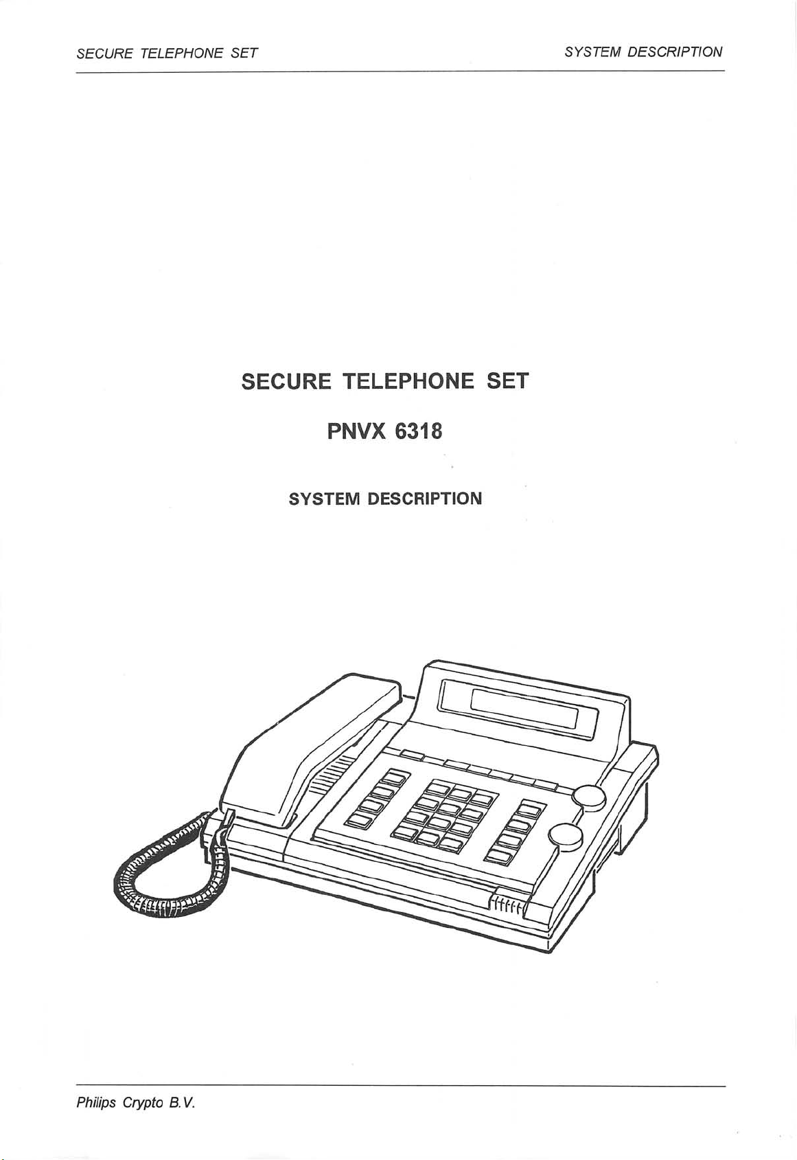
SECURE TELEPHONE SET
PNVX 6318
SYSTEM DESCRIPTION
Philips
Crypto B.V.
PHILIPS
PHILIPS
Page 2
SECURE TELEPHONE SET
SECURE TELEPHONE SET
SYSTEM DESCRIPTION
PNVX 6318
SYSTEM DESCRIPTION
Philips Crypto B. V.
Page 3
S E C U R E T E L E P H O N E S E T S Y S T E M D E S C R I P T I O N
Philips Crypto B. V.
Document No. 9922 154 19463
• Philips Crypto B.V. 1995
All rights reserved
This document is classified commercial in confidence.
It may not be reproduced wholly or partly in any way,
or shown to a third party, without prior permission
from Philips Crypto B.V.
Subject to modification without prior notice.
Printed in The Netherlands
Page 4
S E C U R E T E L E P H O N E S E T S Y S T E M D E S C R I P T I O N
C O N T E N T S P a g e
1 I N T R O D U C T I O N 1
2 S P E C I F I C A T I O N S 2
2 . 1 C r y p t o g r a p h i c s p e c i fi c a t i o n 2
2.2 Electrical specification 2
2 . 2 . 1 E l e c t r i c a l s i g n a l s 2
2 . 2 . 2 B a t t e r y b a c k u p 3
2 . 2 . 3 P o w e r s u p p l y 3
2.3 Mechanical specification 3
2 . 4 N u m b e r s t o r e 4
2 . 5 E n v i r o n m e n t a l c o n d i t i o n s 5
2 . 5 . 1 C l i m a t i c 5
2.5.2 Mechanical 5
2 . 6 S a f e t y 5
2 . 7 T e s t s a n d s e r v i c e a b i l i t y 5
2 . 8 R e l i a b i l i t y 5
2.9 Sealing 6
2 . 1 0 C o m p o s i t i o n , t y p e n u m b e r s a n d a c c e s s o r i e s 6
3 T E C H N I C A L D E S C R I P T I O N 6
3.1 General 7
3.2 Working 8
3.2.1 Introduction 8
3 . 2 . 2 F u n c t i o n a l p a r t s o f b l o c k d i a g r a m 8
3.2.3 Survey of operational situations of the Secure Telephone Set 15
4 O P E R A T I O N 1 7
5 G L O S S A R Y O F T E R M S A N D A B B R E V I A T I O N S 2 1
ILLUSTRATIONS
F i g . 1 : P h i l i p s S e c u r e T e l e p h o n e S e t P N V X 6 3 1 8 1
F i g . 2 : S e c u r e T e l e p h o n e S e t : d i m e n s i o n s 4
F i g . 3 : S e c u r e T e l e p h o n e S e t : s i m p l i fi e d b l o c k d i a g r a m 7
Fig. 4: Secure Telephone Set: firmware control 9
Fig. 5: RS232-C/CCITT V.24 interface 11
F i g . 6 : K e y C a r d I n t e r f a c e : b l o c k d i a g r a m 1 2
F i g . 7 : S u r v e y o f s y n c h r o n i s a t i o n / r e s y n c h r o n i s a t i o n 1 3
F i g . 8 : S u r v e y o f o p e r a t i o n a l s i t u a t i o n s 1 5
F i g . 9 : S e c u r e T e l e p h o n e S e t : b l o c k d i a g r a m 1 6
F i g . 1 0 : S e c u r e T e l e p h o n e S e t : c o n t r o l s 1 7
Fig. 11: Keypad layout 20
P h i l i p s C r y p t o B . V . / / /
Page 5
SECURE TELEPHONE SET SYSTEM DESCRIPTION
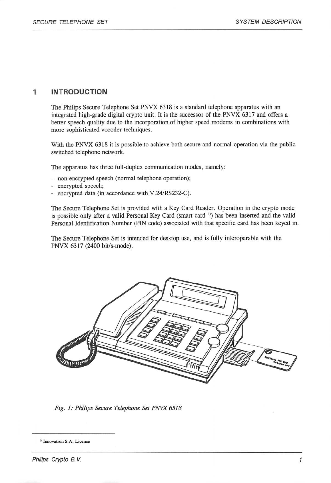
INTRODUCTION
The Philips Secure Telephone Set PNVX 6318 is a standard telephone apparatus with an
integrated high-grade digital crypto unit. It is the successor of the PNVX 6317 and offers a
better speech quality due to the incorporation of higher speed modems in combinations with
more sophisticated vocoder techniques.
With the PNVX 6318 it is possible to achieve both secure and normal operation via the public
switched telephone network.
The apparatus has three full-duplex communication modes, namely:
- non-encrypted speech (normal telephone operation);
- encrypted speech;
- encrypted data (in accordance with V.24/RS232-C).
The Secure Telephone Set is provided with a Key Card Reader. Operation in the crypto mode
is possible only after a valid Personal Key Card (smart card °) has been inserted and the valid
Personal Identification Number (PIN code) associated with that specific card has been keyed in.
The Secure Telephone Set is intended for desktop use, and is fully interoperable with the
PNVX 6317 (2400 bit/s-mode).
Fig. 1: Philips Secure Telephone Set PNVX 6318
'} InnovatronS.A. Licence
Philips Crypto B. V.
Page 6
SECURE TELEPHONE SET
2 S PE C I FI C AT I ON S
2.1 Cryptographic specification
The cryptographic specification is classified information and can be obtained on request at the
NLNCSA.
2.2 Electrical specification
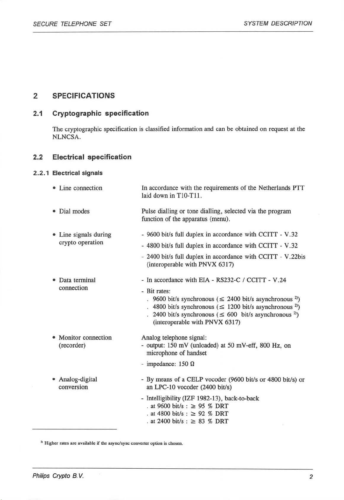
2.2.1 Electrical signals
• Line connection In accordance with the requirements of the Netherlands PTT
laid down in T10-T11.
SYSTEM DESCRIPTION
• Dial modes
Line signals during
crypto operation
Data terminal
connection
• Monitor connection
(recorder)
Analog-digital
conversion
Pulse dialling or tone dialling, selected via the program
function of the apparatus (menu).
- 9600 bit/s full duplex in accordance with CCITT - V.32
- 4800 bit/s full duplex in accordance with CCITT - V.32
- 2400 bit/s full duplex in accordance with CCITT - V.22bis
(interoperable with PNVX 6317)
- In accordance with EIA - RS232-C / CCITT - V.24
- Bit rates:
. 9600 bit/s synchronous (< 2400 bit/s asynchronous 2))
. 4800 bit/s synchronous (< 1200 bit/s asynchronous 2))
. 2400 bit/s synchronous (< 600 bit/s asynchronous 2))
(interoperable with PNVX 6317)
Analog telephone signal:
- output: 150 mV (unloaded) at 50 mV-eff, 800 Hz, on
microphone of handset
- impedance: 150 fl
- By means of a CELP vocoder (9600 bit/s or 4800 bit/s) or
an LPC-10 vocoder (2400 bit/s)
- Intelligibility (IZF 1982-13), back-to-back
. at 9600 bit/s
. at 4800 bit/s
. at 2400 bit/s
> 95 % DRT
> 92 % DRT
> 83 % DRT
21 Higher rates are available if the async/sync converter option is chosen.
Philips Crypto B.V.
Page 7
SECURE TELEPHONE SET
SYSTEM DESCRIPTION
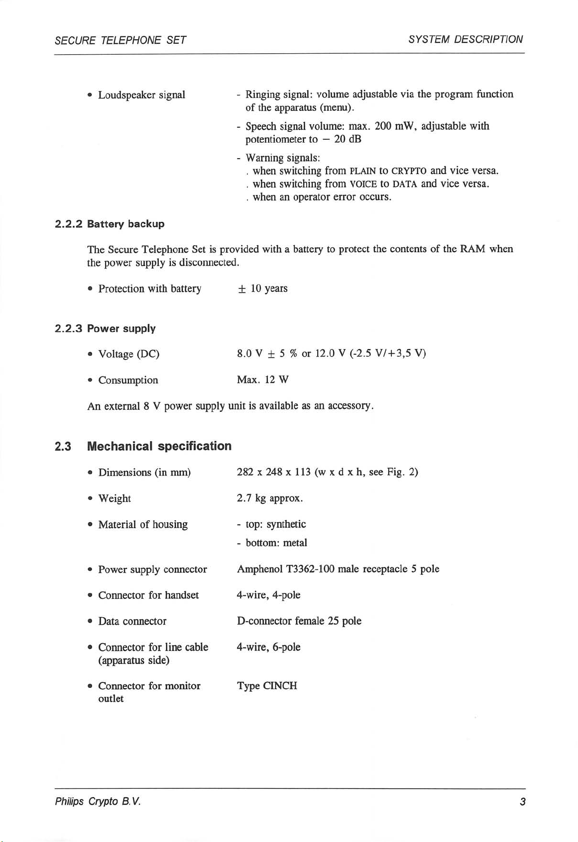
Loudspeaker signal
2.2.2 Battery backup
The Secure Telephone Set is provided with a battery to protect the contents of the RAM when
the power supply is disconnected.
Protection with battery
2.2.3 Power supply
• Voltage (DC) 8.0 V ± 5 % or 12.0 V (-2.5 V/ + 3,5 V)
• C o n s u m p t i o n M a x . 1 2 W
- Ringing signal: volume adjustable via the program function
of the apparatus (menu).
- Speech signal volume: max. 200 mW, adjustable with
potentiometer to - 20 dB
- Warning signals:
. when switching from plain to CRYPTO and vice versa.
. when switching from VOICE to data and vice versa.
. when an operator error occurs.
±10 years
An external 8 V power supply unit is available as an accessory.
2.3 Mechanical specification
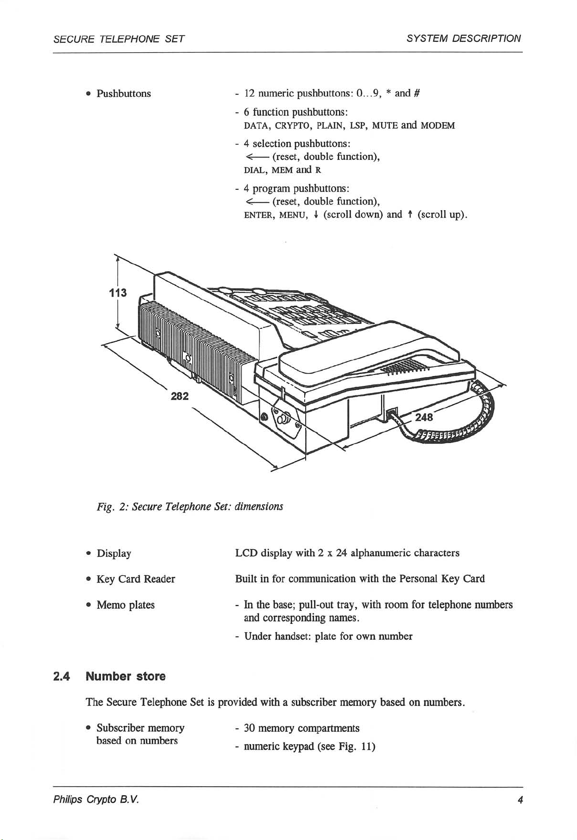
• Dimensions (in mm) 282 x 248 x 113 (w x d x h, see Fig. 2)
• W e i g h t 2 . 7 k g a p p r o x .
• Material of housing
• Power supply connector
• Connector for handset
• Data connector
• Connector for line cable
(apparatus side)
• Connector for monitor
outlet
- top: synthetic
- bottom: metal
Amphenol T3362-100 male receptacle 5 pole
4-wire, 4-pole
D-connector female 25 pole
4-wire, 6-pole
Typ e CIN CH
Philips Crypto B. V.
Page 8
SECURE TELEPHONE SET
Pushbuttons 12 numeric pushbuttons: 0...9, * and #
SYSTEM DESCRIPTION
6 function pushbuttons:
DATA, CRYPTO, PLAIN, LSP, MUTE and MODEM
4 selection pushbuttons:
< (reset, double function),
dial, mem and R
4 program pushbuttons:
< (reset, double function),
enter, menu, i (scroll down) and t (scroll up).
Fig. 2: Secure Telephone Set: dimensions
• Display
• Key Card Reader
• Memo plates
2.4 Number store
The Secure Telephone Set is provided with a subscriber memory based on numbers.
Subscriber memory
based on numbers
LCD display with 2 x 24 alphanumeric characters
Built in for communication with the Personal Key Card
- In the base; pull-out tray, with room for telephone numbers
and corresponding names.
- Under handset: plate for own number
30 memory compartments
numeric keypad (see Fig. 11)
Philips Crypto B.V.
Page 9
SECURE TELEPHONE SET
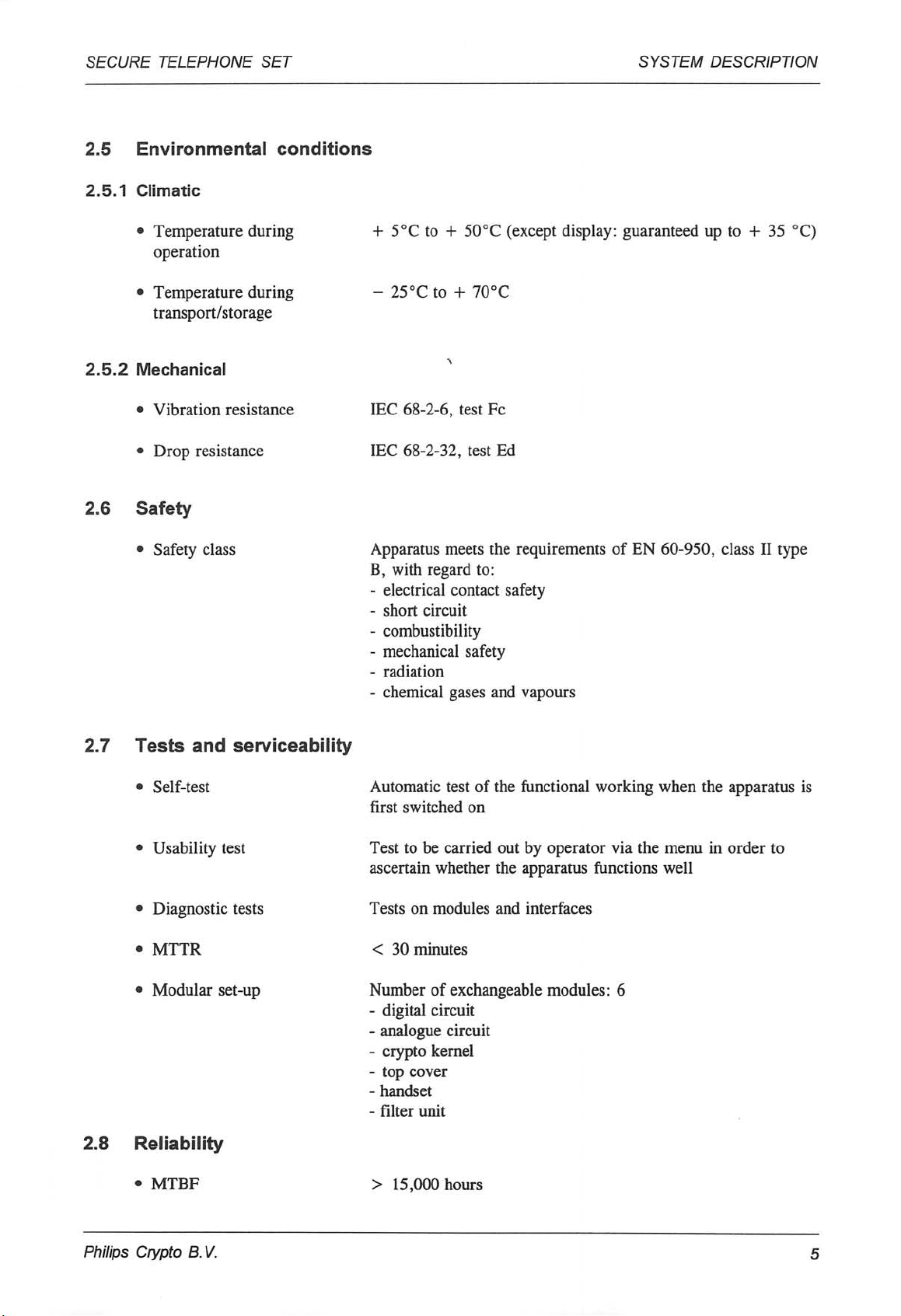
2.5 Environmental conditions
2.5.1 Climatic
SYSTEM DESCRIPTION
• Temperature during
operation
• Temperature during
transport/storage
2.5.2 Mechanical
• Vibration resistance
• Drop resistance
2.6 Safety
• Safety class
+ 5°C to + 50°C (except display: guaranteed up to + 35 °C)
- 25°Cto + 70°C
IEC 68-2-6, test Fc
IEC 68-2-32, test Ed
Apparatus meets the requirements of EN 60-950, class II type
B, with regard to:
- electrical contact safety
- short circuit
- combustibility
- mechanical safety
- radiation
- chemical gases and vapours
2. 7 Te s ts an d ser vi ce abi l ity
• Self-test
• Usability test
• Diagnostic tests
• MTTR
• Modular set-up
2.8 Reliability
• MTBF
Automatic test of the functional working when the apparatus is
first switched on
Test to be carried out by operator via the menu in order to
ascertain whether the apparatus functions well
Tests on modules and interfaces
< 30 minutes
Number of exchangeable modules: 6
- digital circuit
- analogue circuit
- crypto kernel
- top cover
- handset
- filter unit
> 15,000 hours
Philips Crypto B.V.
Page 10

SECURE TELEPHONE SET SYSTEM DESCRIPTION
2.9 Sealing
The Secure Telephone Set is provided with a seal which will be irreparably damaged if the
apparatus is opened.
2.10 Composition, type numbe r s and accessories
• Composition
Typ e numb er s
The Secure Telephone Set consists of the following parts:
- telephone set;
- handset with cable;
- packaging;
- operating instructions.
The Secure Telephone Set is fitted with a type plate bearing
the following text:
Philips Crypto B.V.
Made in Holland
Ty pe U P 63 1 8/X X ( z z) |
N C 9 9 2 2 4 1 6 3 1 8 x x !
N o c c c c d d d d !
INNOVATRON S.A. Licence
8.0 V
1.4 A
xx = version number (01 - 99)
cccc = serial number
dddd = week of production
zz = country code in accordance with UN-D 1157
Accessories
The following accessories are available:
- 8.0 V DC power supply unit;
- Line cable.
- Async/sync converter
Philips Crypto B. V.
Page 11

SECURE TELEPHONE SET
3 TE CHNI CA L DES CR IP TI ON
3.1 General
The Philips Secure Telephone Set is a standard telephone apparatus with a built-in high-grade
crypto unit.
This crypto unit makes use of digital encryption. For that purpose the apparatus is provided
with the means of converting the analog telephone signal into a digital signal and vice versa.
Full-duplex information transfer with a bit rate of 9600 bit/s, 4800 bit/s and 2400 bit/s can be
chosen, using a V32 or V22bis modem.
To obtain a speech transfer of good (fair) quality with these, relatively low, bit rates, two types
of speech coders are used; a CELP vocoder for the bit rates 9600 bit/s and 4800 bit/s and an
LPC-10 vocoder for the bit rate 2400 bit/s.
SYSTEM DESCRIPTION
Because the digital information produced by the crypto unit cannot be transmitted in that form,
the built-in modem converts the digital signal into an analog signal which is suitable for
transmission via the narrow-band (300 - 3400 Hz) Public Switched Telephone Network
(PSTN). At the same time (full-duplex), this modem recovers the original digital signal
encrypted at the other end of the link and offers it to the crypto unit for decryption.
MI C c — o
TEL
DATA o-
VOCODER
(CELP/
LPC-10)
V.24/
RS232-C
INTERFACE
L
o
-o | o-*CRYPTO
UNIT
MODEM
IH
T- Z
J
LINE
INTER
FACE
—o LINE
Fig. 3: Secure Telephone Set: simplified block diagram
Philips Crypto B.V.
o PLAIN
o CRYPTO VOICE
O CRYPTO DATA
Page 12

S E C U R E T E L E P H O N E S E T S Y S T E M D E S C R I P T I O N
3. 2 Wo rk ing
3.2.1 Introduction
The functional description in the following paragraphs is based on the more detailed block
diagram (Fig. 9 - see last page of this part). The most important functional parts of the block
diagram are described.
Following this, Figure 8 gives a survey of the operational states of the Secure Telephone Set
and shows the possible transitions resulting from operation and control commands.
3.2.2 Functional parts of block diagram (see Fig. 9)
■ System processor
The System Processor has full control of the Secure Telephone Set. This includes the control of
the functional units and the digital data flow, and also the initiation of tests (BITs) in the
various units.
Hardware
The System Processor is connected with all essential parts of the apparatus via a bus system.
Although the data flow reproduced in the block diagram (Fig. 9) has been correctly indicated
from a functional point of view, it must be appreciated that the practical realisation of the data
flow is slightly different, because all digital commands are transmitted via the common bus
system controlled by the System Processor.
The System Processor consists of an 80C528-microprocessor, an EPROM, an EEPROM, a
RAM and several ICs for decoding and buffering.
Firmware
The System Processor is controlled by the firmware. In the firmware not only are the various
functions laid down (e.g. authorisation of the user, identification, key selection, etc.), but also
the control and the selection of the various hardware parts.
For instance, the dialling information entered by the user via the pushbuttons is first read by the
firmware and then passed on to the line.
The firmware control is shown schematically in Fig. 4.
■ Analog circuit
The analog circuit forms the interface between the handset, the hands-free microphone, the
loudspeaker control, the monitor outlet, the analog in-/output of the PCM circuit and the plain
switch.
The circuit contains three amplifiers. Two of these are used for the amplification/adaptation of
the microphone and telephone signal; the third is used for the amplification/adaptation of the
monitor signal.
Philips Crypto B. V.
Page 13

SECURE TELEPHONE SET
SYSTEM DESCRIPTION
SWITCHES
ALARM
Presence
RS232/V.24
Data
Command
Audio route
(Plain/Handsfree/
Dial)
Al a rm In t err u pt
Card
Card
Command
Card
J L
KEY CARD KEYBOARD
Response
Voice
Command
VOCODER CRYPTO UNIT
t—i—r
Plain-
Message
Line Command MODEM
FIRMWARE
Dia l D i g i ts
Line Control
Matrix
Code
-Crypto
_L_
DISPLAY
Message
-Crypto
Commands
Display
command
LINE INTERF.
Fig. 4: Secure Telephone Set: firmware control
■ Hands-free circuit
This circuit, which is part of the analog circuit, uses the 'voice switching' principle; a halfduplex connection is set up when the Hands-free function is in use, and the level of the
microphone signal determines whether the microphone or the loudspeaker is switched on (i.e.
whoever is speaking gets the line).
■ Plain switch
The switch-over from plain to crypto, and vice versa, is accomplished with the help of different
types of analog multiplexers controlled by the System Processor.
■ PCM circuit
A/D conversion
In the A/D converter of the PCM circuit, the analog signal from the microphone is converted
into digital information in accordance with the pulse code modulation principle (Linear);
conversion takes place at a sampling frequency of 8 kHz. The digital output consists of 16-bit
words, which are transferred serially to the inlet of the Digital Signal Processor (DSP).
Philips Crypto B. V.
Page 14

S E C U R E T E L E P H O N E S E T S Y S T E M D E S C R I P T I O N
D/A conversion
The digital information from the DSP is transferred to the D/A converter of the PCM circuit,
where it is converted into an analog signal.
■ Digital Signal Processor
The Digital Signal Processor (DSP) has two vocoder functions:
- converting the digital information received from the PCM circuit to a digital stream of data
(and vice versa) according to the CELP principle (CELP = Code Excited Linear Prediction);
- converting the digital information received from the PCM circuit to a digital stream of data
(and vice versa) according to the LPC-10 principle (LPC = Linear Predictive Coding).
The firmware determines which of the two principles will be chosen. For the bit rates
9600 bit/s and 4800 bit/s the CELP principle will be chosen. When a bit rate of 2400 bit/s is
required the LPC-10 principle will be chosen. When interoperability with a Secure Telephone
Set of type PNVX 6317 is required the firmware will choose always the LPC-10 principle.
CELP vocoder
Transmitting end:
Frames of 240 samples from the A/D converter are temporarily stored in a speech buffer.
Every 30 ms a frame is converted into several speech parameters. These parameters contain
such information as quantified LPC filter coefficients. In order to minimise the effects of
transmission errors on bad lines, the most important speech parameters are protected using an
error correction code. The channel coding technique used provides stronger protection for the
most significant bits of these speech parameters. Interleaving is applied to randomise burst
errors and the resulting frame data is transferred to the crypto unit.
Receiving end:
After de-interleaving, error correction is carried out making use of the line quality information
from the modem. Under adverse transmission conditions some speech parameters may be badly
corrupted, this loss of data is concealed by repeating previous good values. The resulting set of
speech parameters are used to synthesise the output speech wave form which is then transferred
to the D/A converter.
LPC-10 vocoder
Transmitting end:
Frames of 180 samples are temporarily stored in a buffer. Every 22.5 ms LPC and pitch
analysis are carried out. The latter is performed using a DFT based harmonic sieve. The
resulting 54 bit data frame, formatted according to STANAG 4198 is transferred to the crypto
unit.
Receiving end:
Every 22.5 ms the crypto unit transfers the received data frame to the DSP. During unvoiced
frames forward error correcting Hamming codes are used to detect the amount of errors on the
channel and to form an estimate of the bit error rate (BER). Depending on the BER estimate
the speech parameters including the pitch are smoothed, thus concealing the channel errors. The
corrected and smoothed data are then used to synthesise the 180 samples of output speech
which are transferred to the D/A converter.
P h i l i p s C r y p t o B . V . 1 0
Page 15

SECURE TELEPHONE SET SYSTEM DESCRIPTION
■ Data/voice switch
The firmware determines which of two sources (DSP or data connection) will be enabled. The
data from the enabled source is passed on to the crypto unit.
■ RS232-C/V.24 interface
This circuit (see Fig. 5) takes care of the interface between the terminal connection and the bus
system (signals/levels are in accordance with V.24/V.28, CCITT).
The input signals are converted to HCMOS-level by level- converter 1 (receiver); the output
signals are converted to the right level by level converter 2 (driver).
D-connector
T
103
105 o
108 o
107
106
104 o—<—
115 o—<—
114 o—«—
109 o—«—
102 o
101
°TL
LEVEL
CONV.
(1)
-\ SYSTEM
-/ PROCESSOR
LEVEL
CONV.
(2)
j_L
HF-radiation protection
cct
pin
meaning
103 2 Data Input
105 4
108 20 Data Terminal Ready
107 6 Data Set Ready
106 5 Clear To Send
104 3 Data Output
115 17 Receive Clock
114 15 Transmit Clock
109 8 Carrier Dete ct
102 7
101 1 Protection Ground (case)
Request To Send
Digital Ground (on PCB)
Fig. 5: RS232-C/CCUT V.24 interface
■ Key Card interface
The Key Card interface detects the presence of the Personal Key Card and makes possible the
interchange of Identification Code and key information between the apparatus and the card. The
correctness of the Identification Code entered by the user is checked by the Personal Key Card.
Philips Crypto B. V.
11
Page 16

SECURE TELEPHONE SET SYSTEM DESCRIPTION
KEY CARD
CONNECTOR
-o Vcc
-o Vpp
PKC
-o GND
-o CLK
-o RST
-o I/O
o o
/
KEY
CARD
INTERFACE
-\ SYSTEM
-/ PROCESSOR
Fig. 6: Key Card Interface: block diagram
■ Crypto unit
General
The cryptographic circuit is implemented as an independent encryption/decryption unit.
Presentation of the input, communication with the Personal Key Card, and the further
processing of the output, are governed by the System Processor. The correctness of the
Identification Code entered by the user is checked by the Key Card.
Encryption/decryption
Encryption and decryption is achieved by means of the stream cipher technique, in which a
pseudo-random bitstream produced by a keystream generator is continuously mixed with the
stream of digital data presented. To protect against active eavesdropping (i.e. hostile
manipulation of the cipher text) and hence to protect the integrity of the transmitted data, a
keystream-dependent non-linear mixing principle is employed.
The pseudo-random bitstream produced by the keystream generator consists of a sequence of
keybits which depends upon the session key and the synchronisation information bits (message
key).
The keystream generator is designed in accordance with the latest cryptographic principles and
is based on Philips Crypto B.V's extensive expertise. Aspects such as key diversity, sequence
complexity and various methods of attack have been taken fully into consideration.
Authentication
When a connection is established the Secure Telephone Set is in the PLAIN VOICE mode. The
transition to the CRYPTO VOICE mode is initiated by pressing the CRYPTO button. Transition
to the CRYPTO DATA mode is initiated by pressing the data button.
A Peer Entity Authentication Protocol is exchanged between both crypto units for identity
check, key selection and authentication before communication in crypto can be established.
User Identification
The identity of each user (Key Card) known by the input of the correct Identification-code
(access control) is coded and sent to the other party.
Philips Crypto B. V.
12
Page 17

SECURE TELEPHONE SET SYSTEM DESCRIPTION
Key selection
If the identity of the other party is recognised and valid, each telephone set will retrieve (and
decrypt) the pairwise unique key information from its Key Card.
Peer Entity Authentication
A 'signature' calculated and coded by each party on basis of the pairwise unique key is sent to
the other party.
The verification of the signature received will guarantee the integrity of the other party (i.e. the
identified other party uses indeed the correct key).
Session key and synchronisation
When the authentication protocol is run through successfully both crypto units determine the
'session key'. Crypto synchronisation of the receiver is achieved by using the synchronisation
information bits received from the other party.
When synchronisation is achieved, both telephone sets adopt the CRYPTO VOICE (CRYPTO
DATA) mode. They can both be returned to the PLAIN mode by pressing the plain button.
Resynchronisation
Once both parties have been synchronised, it may subsequently become necessary to
synchronise again. In that case only synchronisation patterns are transmitted/received.
"CRYPTO" "DATA"
"CRYPTO" "DATA"
= authen ticatio n, key select ion and synch ronis ation
= res ynchronisation
Fig. 7: Survey of synchronisationlresynchronisation
Resynchronisation takes place in the following cases:
• if the crypto button is pressed during 'Crypto Voice' (to regain synchronisation after
disturbance of the line synchronisation)
• if the data button is pressed during 'Crypto Voice', as a consequence of which the
apparatus switches over to 'Crypto Data';
• if the crypto button is pressed during 'Crypto Data', as a consequence of which the
apparatus switches over to 'Crypto Voice';
Philips Crypto B. V. 13
Page 18

S E C U R E T E L E P H O N E S E T S Y S T E M D E S C R I P T I O N
• if the data button is pressed during 'Crypto Data' (to regain synchronisation after
disturbance of the line synchronisation).
• automatically during 'Crypto voice', if 'out of sync' is detected.
• after line signal interruptions (not more than 30 seconds). At 2400 bit/s not only a crypto
resynchronisation but also a modem resynchronisation takes place.
■ Modem
The modem converts the digital information presented (crypto-voice or crypto-data) into analog
signals suitable for the line, and vice versa.
During transmission the analog signal (carrier wave) is modulated with the digital signal
supplied from the crypto unit.
The digital signal transmitted by the other party is regained (demodulation) from the received
(analog) line signal and offered to the crypto unit for decryption. In this way the modem is
capable of processing full-duplex data at the chosen bit rate.
■ Dial circuit
This circuit receives the dialling information via the System Processor.
The circuit which is provided with anti-bounce measures, codes the pressing of a key into the
associated pulse or tone code and switches off the telephone/microphone signal route during
dialling (mute).
■ DC/DC-separation
Because the line interface circuit is fed from the line and the other circuits from the power
supply unit of the Secure Telephone Set, DC/DC-separation is incorporated; relays,
transformers and opto-couplers are applied at the points concerned.
■ Line interface
The universal line interface arranges the transfer of the analog signals from the Secure
Telephone Set to the public switched telephone network and vice versa.
This circuit also contains the hook relay, which is controlled by the hook contact signal
received from the System Processor.
■ Ringing signal detector
The ringing signal detector generates a control signal when the ringing signal is received from
the line. This control signal is transferred to the System Processor, which generates an
adjustable acoustic signal for the loudspeaker.
■ Recall circuit
When the R button is pressed (and the 'enable enquiry' facility is installed), the line connections
('a' and 'b') are connected to E. If the 'register recall' facility is installed, pressing the R button
will interrupt the line current for approx. 100 ms.
■ DC/DC converters
The built-in DC/DC converters supply the required DC voltages. The input voltage for these
converters is derived from an external DC power supply unit via a connector incorporated in
the housing.
P h i l i p s C r y p t o B . V . 1 4
Page 19

SECURE TELEPHONE SET SYSTEM DESCRIPTION
The required DC input voltage is 8 V.
The DC/DC converters supply the following output voltages: +5 V, -5 V, +24 V and +7 V.
3.2.3 Survey of operational situations of the Secure Telephone Set
«POWER 0N»
POWER OFF INITIALISATION
+
INTERNAL TEST
«MENU»
I—<- MENU PRE-DIALLING
«ON HOOK» a «OFF HOOK» ▼ KEY CARD
DIALLING
«D ATA» or |
«CRYPTO» ▼ [«SYNC DETECT»]t
\ , , l _
TX PROTOCOLS RX PROTOCOLS
TX SYNC
«CRYPTO»
or
«DATA»
ON HOOK / STAND BY
Jm
PLAIN VOICE
RX SYNC
[resi
▼ detect]a a
KEY CARD
CONTROL
CONTROL
cnc
CRYPTO VOICE or
CRYPTO DATA
«ON HOOK»
(crypto voice only)
«PLAIN» ▼ received]
«...» = by operation
[...] = by control signal
Fig. 8: Survey of operational situations
[message "plain"
Philips Crypto B.V.
15
Page 20

pulse dial
SWITCH
DIAL/PLAIN/CRYPTO
0 E
LINE
LINE
INTERF.
RING.
CIRC.
DC/DC separation
do •
p o—o
PLAIN SWITCH »
parts
u n d er c on tr ol
L2
CLOCK CIRCUIT
HOOK SWITCH
UNIT
CRYPTO
SWITCH
VOICE/ |—▶-
DATA
l_
1 GND
-▶ 4 7 V
♦ « p ar t u nde r co nt rol of t he S ys tem Pr oce ss or
oc » o pt o -c ou p l e r
t r - t ra n sf o rm e r
r el = r el a i s
PKC » Perso nal K ey Card
PLAIN
SWITCH
ANALOG
MIC
CIRCUIT
TEL
MON
HANDS ♦
MIC
FREE
LSP
RS232-C ♦
V.2 4
INTERFACE
KEY CARD ♦
INTERFACE
DC/DC
CONVERTER
2
S3
I
SI
f
3
Page 21

SECURE TELEPHONE SET
OPERATION
The Secure Telephone Set has the following operational facilities:
Key Card Reader
Before the Secure Telephone Set can be used for crypto operation, the apparatus must be
provided with a valid Personal Key Card, which must be inserted into a slot on the right-hand
side of the Secure Telephone Set. The correct Personal Identification Code for that Key Card
must then be keyed in.
SYSTEM DESCRIPTION
1 H a n d s e t
2 P r o g r am p us h b ut t o ns
3 D i s p l a y
4 Disp l a y c o n t r a st control
5 K e yc ar d r ea de r
Numerical pushbuttons
By means of the numerical pushbuttons 0 ... 9, * and #, it is possible to enter a subscriber
number, to enter the required Personal Identification Code, to select a number from the
subscriber number store, to enter a new number into the number store or to note a subscriber
number during a conversation (MEMO function).
Philips Crypto B. V.
6 Personal Key Card
7 Memo plate
8
Loudspeaker volume control
9
Facility and Function keys
10 Numerals
Fig. 10: Secure Telephone Set: controls
17
Page 22

S E C U R E T E L E P H O N E S E T S Y S T E M D E S C R I P T I O N
Function pushbuttons
The function pushbuttons are: CRYPTO, PLAIN, DATA, LSP, mute and MODEM.
The CRYPTO button is used to switch over from plain-voice or crypto-data mode to crypto-voice
mode.
The PLAIN button is used to switch over from crypto-voice or crypto-data mode to plain-voice
mode.
The data button is used to switch over from plain-voice or crypto-voice mode to crypto-data
transmission via the RS232-C connection. By means of the crypto button switching over from
crypto data to crypto-voice is possible.
The 'hands-free' function is switched on (handset is on-hook) by pressing the LSP button. This
switches the apparatus off-hook and switches on the built-in loudspeaker and special
microphone. The 'hands-free' function is also activated in the plain-voice or crypto-voice mode
when the handset is replaced while the LSP button is pressed.
The 'hands-free' function is cancelled, and the on/off-hook function taken over by the hook
contact, by pressing the LSP button once again.
Pressing the LSP button in plain-voice mode (handset off-hook) switches on the built-in
loudspeaker. The 'loudspeaking' function is cancelled again by pressing the LSP button again.
Replacing the handset with 'loudspeaking' function switched on and pressing the LSP button
enables the 'handsfree' function.
Pressing the mute button suppresses the microphone signal; the situation is restored by
pressing the mute button again.
The modem button is used to change the modem startup speed. The modem startup speed can
be changed in plain-voice mode or when the handset is on-hook. The modem button is also
used to change the bit rate in crypto-voice and crypto-data mode.
Selection pushbuttons
The < button is used to erase display information during the telephony function.
The dial button initiates a call to the subscriber number shown in the display (also REDIALfunction).
Pressing the mem button makes it possible to initiate a call to one of the pre-programmed
subscriber numbers.
By means of the R button - and in plain-voice mode only - a conversation with someone else
can be started and finished, provided that this facility is supported by the local switched
telephone network and installed via the ENABLE ENQUIRY menu option.
The R button can also be programmed via the menu as REGISTER RECALL if this facility is
supported by the local switched telephone network.
Program pushbuttons
Via the program buttons menu, I (scroll down), t (scroll up) and ENTER, the user has access
to the menu facilities, such as: storing and changing subscriber numbers, changing (software)
settings, and carrying out the (internal) off-line diagnosis tests or the user test.
Some menu facilities can be used only when the Key Card has been inserted and the associated
Personal Identification Code has been accepted.
P h i l i p s C r y p t o B . V . 1 8
Page 23

S E C U R E T E L E P H O N E S E T S Y S T E M D E S C R I P T I O N
Zeroize
All key material present in the PNVX (i.e. the red key material stored in the RAM) will be
erased when the crypto and ■* keys are pressed simultaneously. As a result, the
apparatus and the inserted Key Card are rendered unusable for all crypto functions. The crypto
functions of the apparatus can only be put back into service following a complete crypto
installation procedure. A zeroized Key Card can be programmed again.
Zeroizing is possible only if the zeroize function is made available during crypto installation.
On hook/off hook switch
The Secure Telephone Set has the usual hook contact.
Auto-answer facility
The PNVX 6318 will automatically set up a crypto data connection after detection of an
incoming call on the condition that the auto-answer mode has been enabled via the menu.
Display
The display contains two lines of 24 characters.
The upper line (state line) gives information with regard to the state of the Secure Telephone
Set, e.g. I plain voice 4.8 | is displayed when the apparatus is functioning as a normal
telephone (i.e. when speech is not being encrypted) and that the modem startup speed will be
4800 bit/s when switching over to crypto-voice or crypto-data mode.
I plain voice lsp 2.4 | in the upper line of the display indicates that the user has selected the
'loudspeaking' function and that the modem startup will be 2400 bit/s.
I crypto voice 2.4 | denotes that crypto security has been established, so that only
encrypted speech is passed to the line. '2.4' indicates that the actual bit rate equals 2400 bit/s.
I crypto voice hfr 9.6 I in the upper line of the display indicates that the user has selected the
'handsfree' function and that the actual bit rate is equal to 9600 bit/s.
I crypto data 4.8 I denotes that the apparatus is in the crypto-data mode (4800 bit/s) and
that crypto security is guaranteed.
The lower display line shows the information which plays a supporting part in the operation of
the Secure Telephone Set, e.g. a keyed-in subscriber number, a menu line, etc.
Modem Speed
The modem speed is the bit rate the CELP vocoder (9600 or 4800 bit/s) or LPC-10 vocoder
(2400 bit/s) uses during a crypto voice or crypto data connection.
The PNVX will use the modem startup speed to setup a crypto connection. This modem startup
speed can be the one which has been stored together with the subscriber number in the number
memory or the default one (which has been designated via the menu). The modem startup speed
can be changed by pressing the MODEM button when the handset is replaced or during a plain
voice connection.
If synchronisation is not possible at the modem startup speed (e.g. poor line or PNVX 6317 at
the other end) and if the "Auto fallback mode" is enabled, the PNVX 6318 will automatically
try to synchronise at a lower modem speed.
P h i l i p s C r y p t o B . V . 1 9
Page 24

SECURE TELEPHONE SET SYSTEM DESCRIPTION
The modem speed can also be changed manually during a crypto connection by pressing the
modem button. The PNVX will then use the new modem speed and re-synchronise.
Keypad layout
DATA enter MENU i t MODEM
CRYPTO 1 2 3
n-x-o
PLAIN 4 5 6 MEM
LSP 7 8 9
MUTE
*
0 # R
Fig. 11: Keypad layout
«-
rr-x-o
DIAL
Philips Crypto B.V. 20
Page 25

SECURE TELEPHONE SET
GLOSSARY OF TERMS AND ABBREVIATIONS
SYSTEM DESCRIPTION
TERM/ABBREVIATION
A/D
BER
BIT
CCITT
CCITT-V.22bis
CCITT-V.24
CCITT-V.28
CCITT-V.32
DESCRIPTION
Analog-digital
Bit Error Rate
Built-in Test
Comite Consultatif International Telephonique et
Te l e g r a p h i q u e
2400 bit/s duplex modem using the frequency division
standardised for use on the general switched telephone
network and on point-to-point 2-wire leased telephone-type
circuits.
List of definitions for interchange circuits between Data
Terminal equipment (DTE) and Data Circuit-terminating
Equipment (DCE).
Electrical characteristics for unbalanced double-current
interchange circuits.
A family of 2-wire, duplex modems operating at data
signalling rates of up to 9600 bit/s for use on the general
switched telephone network and on leased telephone-type
circuits.
CELP
CLK
CONV.
D/A
DFT
DRT
DSP
EEPROM
EIA
EPROM
GND
HCMOS
HF
Code Excited Linear Prediction
Clock pulse
Converter
Digital-analog
Discrete Fourier Transform
Diagnostic Rhyme Test
Digital Signal Processor
Electrically Erasable Programmable Read-Only Memory
Electronic Industries Association
Erasable Programmable Read-Only Memory
Ground
High-speed CMOS
High Frequency
Philips Crypto B. V.
21
Page 26

SECURE TELEPHONE SET
SYSTEM DESCRIPTION
TERM/ABBREVIATION
HFR
I/O
IZF
kB
LCD
LPC
LSP
MIC
MON
MTBF
MTTR
oc
PCM
DESCRIPTION
(continued)
HandsFRee
Input/Output
Instituut voor Zintuig Fysiologie (Institute for Sensory
Physiology)
kiloByte
Liquid Crystal Display
Linear Predictive Coding
LoudSPeaking (or LoudSPeaker)
Microphone
Monitor
Mean Time Between Failures
Mean Time To Repair
Opto-coupler
Pulse Code Modulation
PKC
PSTN
RAM
rel
RS232-C
RST
SYNC
TEL
tr
VOCODER
Personal Key Card
Public Switched Telephone Network
Random-Access Memory
Relay
Recommended Standard concerning: Interface between data
terminal equipment and communication equipment employing
serial binary interchange.
Reset
Synchronisation
Te l e p h o n e
Transformer
Voice Coder
Philips Crypto B.V.
22
Page 27

I Cfiiplo Museum %
1 I «™™. crvptQmuseum.com
 Loading...