

Page 1
Mounts by
A division of David Engineering & Mfg. Inc.
Model
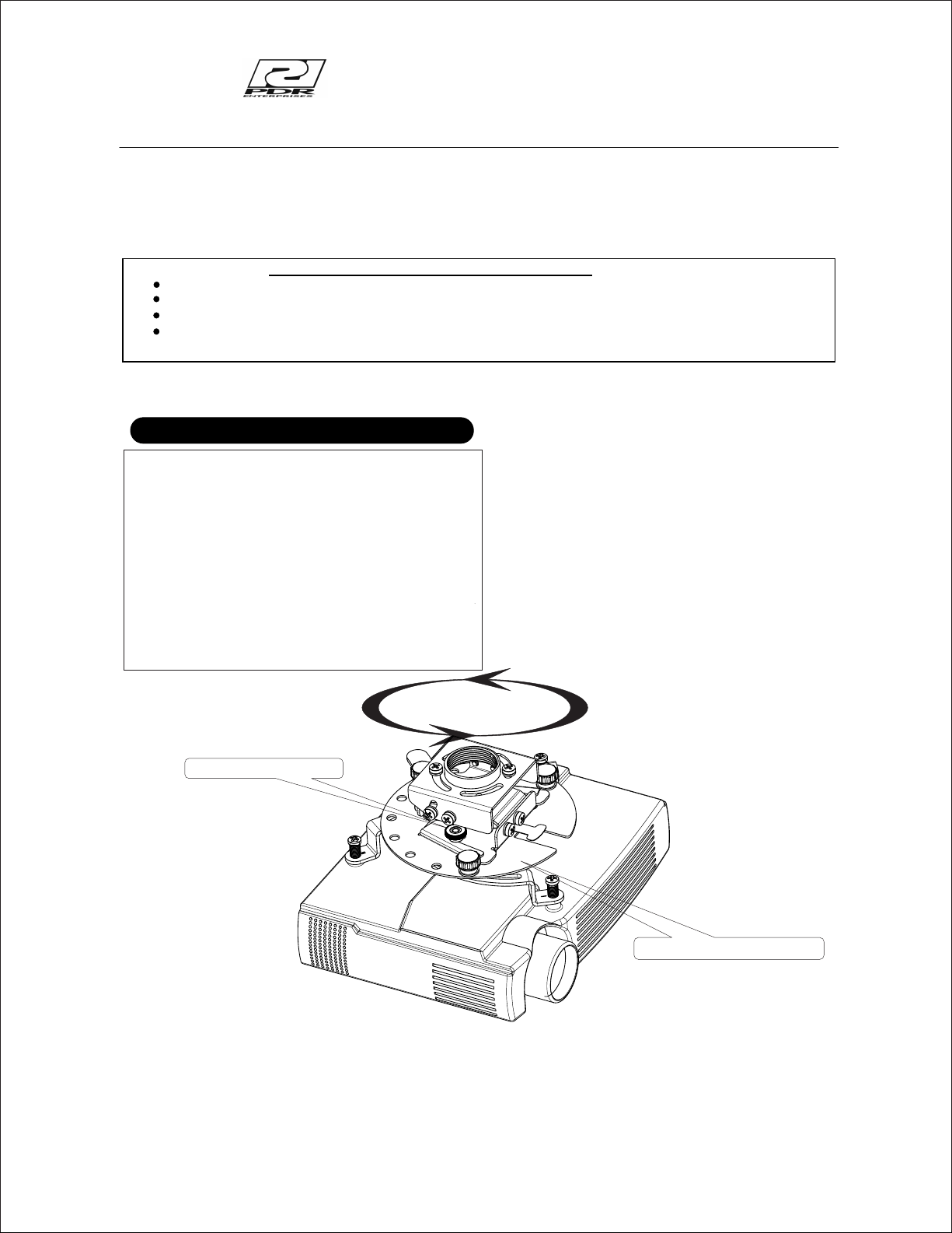
PMU50 PROJECTOR MOUNT
Thank you for purchasing the PDR Projector mount with the exclusive “Bayonet locking system”.
To ensure the correct usage, please read and follow the instructions
All PDR mounts and adapters carry a lifetime warranty against defects in material and workmanship. We are not liable for
improper installation that results in damage to mounts, adapters or presentation equipment.
To ensure customer safety, be sure to decide the installation location so that the strength is sufficient to withstand the weight of both the projector
and the mount.
Fully tighten all of the mounting screws as specified in the instructions.
Do not attempt to perform this work by yourself.
Request an installation specialist to install this unit.
Manufacturer assumes absolutely no responsibility for injuries and damages that may occur due to improper installation and handling.
Please remember that if you remove the mount from the wall/ceiling later, you will find the screw holes and anchor bolts for the
mounting unit left on the wall.
Special techniques are necessary for installation of the mount.
Features
manual thoroughly. Please store the instructions in a safe place
! Simple to adjust no-tools required
3 1/4 ”
! Low profile
! 1 ½”NPT-ready or flush mount
! +30° -5° Pitch
! + -5° yaw
! 360 ° rotation
! 55 lb load rating
! Lateral shift capable
! Quick projector removal with exclusive
“Bayonet locking system”
for future reference.
Locking thumb screw
Rotate 360 deg
Bayonet Locking System
1
Page 2

INSTALLATION LOCATION
The ceiling where the mount is to be installed must be capable of long-term support of
the total load of the projector and mount. Measures should be taken to ensure sufficient
strength to withstand the force of earthquakes, vibrations and other external forces.
Note:
Incorrect installation can cause the projector mount to fall and cause injury.
Total load of the mount (projector + Mount)
Maximum weight - 55 Lbs (25Kg.)
WARNING
INSTALLATION ON A WOODEN CEILING STRUCTURE
Always install so that the load is supported by a wood beam. If
Do not install on decorative ceilings or plaster board.
Avoid installing in locations where the temperature and humidity are excessively high, and where contact with any
water is possible. These can result in fire or electric shock.
Do not install close to an air conditioner intake or outlet. Do
oily smoke or tobacco smoke. Fire could result.
Do not block the ventilation holes. Leave sufficient clearance in regard to the surroundings to avoid blocking the ventilation..
The internal temperature could elevate and possibly result in fire. Install the projector (4") or more away from surroundings.
Do not install in locations where there is excessive vibration or impact. Injury and damage could result from the projector mount
falling.
Do not install where there is direct sunlight or other strong
.
the strength of the wood beam is not sufficient, add reinforcement.
Always confirm the center of the beam is used for the installation.
CAUTION
not install in locations where there are excessive amounts of dust,
.
light. Strong light could result in eye fatigue during usage.
Use the specified bolts and screws in the specified places and tighten firmly. Failure to do this could cause injury if the projector
mount falls.
Do not alter any of the parts. Do not use broken parts. This
C a u ti o n : I n s t a ll a t io n o f u n i t i s t o be c a rr i e d o u t b y q u a l i fi e d te c h ni c i an s o nl y. I n s t al l in a n ap p r op r i at e
l o c at i o n b y c h e ck i n g t h e w a ll s tr u c tu r e an d d ur a bi l i ty f o r s a f e t y a n d a c c i d en t p re v en t i on .
WARNING
could result with injury due to the projector mount falling. .
REV 031708
2
Page 3

PRODUCT SPECIFICATIONS
5°
5°
2.13”
3.26”
30°
Ø
15.75” MAX REACH
5°
3
Page 4

ADAPTER PLATE HARDWARE
A
B
C
D
E
F
G
H
I
M2.6 x 25mm Cheese Head slotted machine Screw 4 pcs
J
K
L
M
O
P
M6 x 25mm Pan Head Philips machine Screw 4 pcs
M4 x 25mm Pan Head Philips machine Screw 4 pcs
M 3 x 25mm Pan Head Philips machine Screw 4 pcs
1/4-20 x 5/8 carriage bolts 4 pcs
9/32” x 47/64” Nylon washer 4 pcs
4.3 mm x 8.9mm steel washer 4pcs
2.7mm x 6mm steel washer 4 pcs
Note: must be used with washer “E”
Leveling barrels 4 pcs
Black plastic knob 4 pcs
Adjustable arm (left) 2 pcs
Adjustable arm (right) 2 pcs
Adapter plate 1 pc
1/4” X 2” lag bolt 2 pcs
9/32” ID steel washer 2 pcs
Fig 1
A
K
4
G,H,I,J
D,E
F
C
M
B
L
Page 5

1. FASTEN THE PROJECTOR MOUNT TO 1 ½”NPT PIPE
1: The bracket must be secured to a ceiling structure capable of at least
2: Screw the bayonet sub assembly onto the 1 ½” NPT pipe (not supplied).
3: Secure with the locking set screw making sure the sub assembly safety lever is facing the front of the projector.
4: Fine adjustment can be made for rotation by loosening the two screws on the 1 ½’collar and rotating to the desired
position and tighten the two screws. SEE FIG 2
(4) times the weight of the projector + mount.
Fig 2
Pipe Not Supplied
Bayonet Sub Assembly
Projector Front
locking set screw
safety lever
Rotation screws
2. FLUSH MOUNTING THE PROJECTOR MOUNT
1: The bracket must be secured to a ceiling structure capable of at least (4) times the weight of the projector + mount.
2: For flush mounting of the pmu50 remove the 1 ½” collar and the side screws.
3: Position the pmu50 mounting plate against the ceiling structure with the chamfer facing the rear of the viewing screen (a solid wood
construction is required behind any ceiling structure). SEE FIG 3
4: Using the two lag bolts and washer supplied fasten to the ceiling.
5: Re-attach the bottom part of the mount using the side screws removed earlier. SEE FIG 3
Fig 3
Wood beam
Front of mount
Chamfer facing away
from the viewing screen
Side screws
P
O
5
Page 6

3. ATTACH THE ADAPTER PLATE TO THE PROJECTOR.
1: Start by screwing the leveling barrels ( A ) into the Adjustable arms (K and L). A screwdriver slot is provided in the barrel (A). The barrels only
need to be threaded approx. 1/8“ through the bottom of the arm (K and L). If the mounting plane of the projector is not flat, the barrels can be
adjusted to make up the difference in height. SEE FIG 1
2: Using the adapter plate ( M ) attach the adjustable arms ( K,L ) with the hardware supplied (B,C,F). No need to tighten at this time. SEE FIG 1
3: Place the Universal adapter plate onto the projector. Using the proper hardware supplied ( screws G,H,I,or J) (washers D or E )
lightly fasten to the projector. SEE FIG 3
4: Position the universal adapter plate approx over the center of the projector. Tighten the screws to the projector and then tighten the plastic knobs
(If needed you can also adjust the adapter plate assembly to access the filters and light source, or for lateral shift to suit)
Be careful to not over-tighten the projector screws.
Damage to the projector may occur if the screws to the projector are over tightened.
Fig 3
Adapter Plate Assembly
Projector assembly
4. MOUNT THE PROJECTOR ASSEMBLY TO THE PROJECTOR MOUNT
1: Place the projector assembly into the bayonet slots on the mount (small end into large end) and slide backward until
the safety lever engages SEE FIG 4.
2: Adjust the locking thumb screws to secure the mount to the projector.
3: To remove, loosen the thumb screws and lift the safety lever to slide the unit out.
4: Adjust for best view and tighten all hardware.
Bayonet Sub Assembly
Fig 4
Safety lever
Locking thumb screw
Projector assembly
6
 Loading...