

Philips PCK2021DGG, PCK2021DL Datasheet
INTEGRATED CIRCUITS
PCK2021
CK00 (100/133 MHz) spread spectrum
differential system clock generator
Product data
File under Integrated Circuits, ICL03
2001 Oct 11
Philips Semiconductors Product data
CK00 (100/133 MHz) spread spectrum
differential system clock generator
FEA TURES
•3.3 V operation
•Six differential CPU clock pairs
•Two PCI clocks at 33 MHz and one 3V66 clock
•Two 48 MHz clocks at 3.3 V
•One 14.318 MHz reference clock
•Power management control pins
•Host clock jitter less than 200 ps cycle-to-cycle
•Host clock skew less than 150 ps pin-to-pin
•Spread Spectrum capability
•Optimized frequency and spread spectrum performance
DESCRIPTION
The PCK2021 is a clock synthesizer/driver for a Pentium III and
other similar processors.
The PCK2021 has six differential pair CPU current source outputs,
two 33 MHz outputs, one 3V66 output, and two 48 MHz clocks
which can be disabled on power-up, and one 3.3 V reference clock
at 14.318 MHz which can also be disabled on power-up.
The part possesses a dedicated power-down input pin for power
management control. This input is synchronized on chip, and
ensures glitch-free output transitions. In addition, the part can be
configured to disable the 48 MHz outputs for lower power operation
and an increase in the performance of the functioning outputs. The
REF and PCI outputs can also be disabled for the highest
performance of the Host outputs.
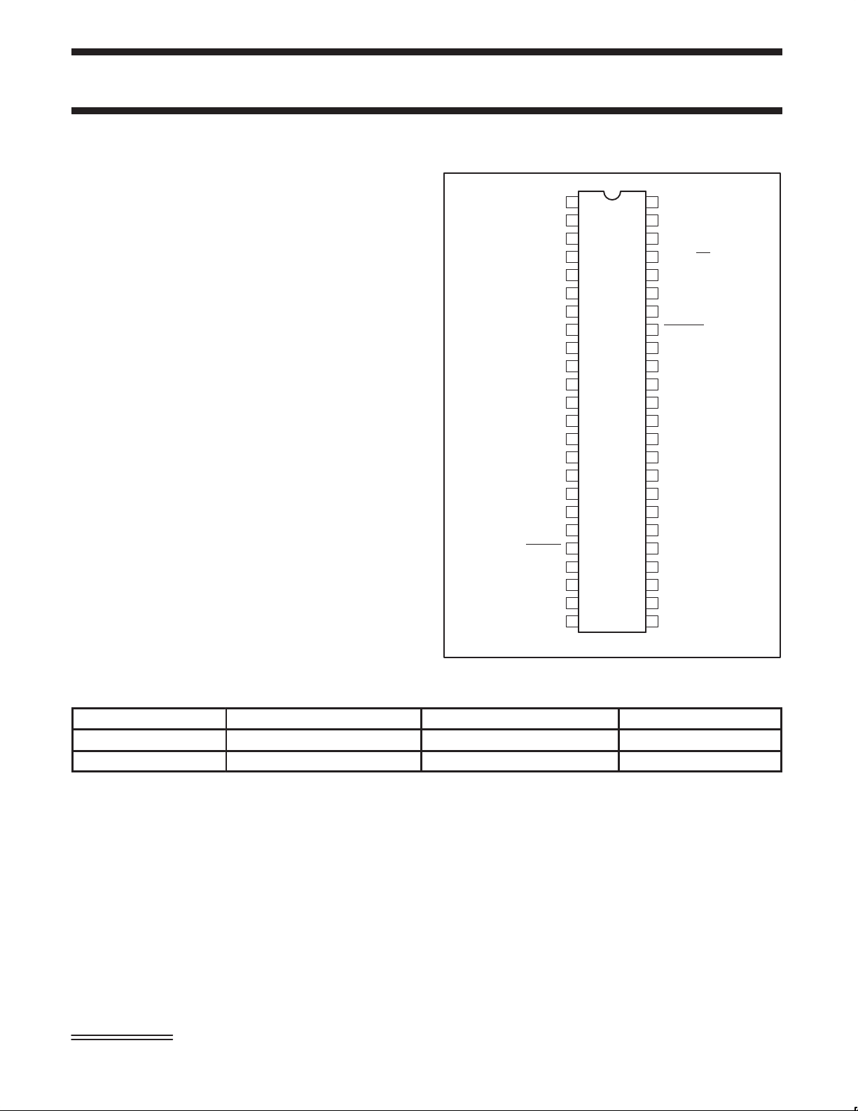
PIN CONFIGURATION
1
DDPCI
2
V
DD48
V
3V66
V
SS3V66
V
DD3V66
V
DDCPU
HCLK0
V
DDCPU
V
SSCPU
HCLK2
V
DDCPU
V
SSREF
XOUT
V
DDREF
SS48
REF
XIN
3
4
5
6
7
8
9
10
11
12 37
13
14
15
16
17
18 31
19 30
20
21
22
23
24 25
48M_0/SELA
48M_1/SELB
HCLKB0
HCLKB1
HCLKB2
PCK2021
48V
PCI0
47
PCI1
46
V
SSPCI
45
SEL133/100
44
NC
43
V
DDA
42
V
SSA
PWRDWN
41
40
V
DDCPU
39
HCLK3
38
HCLKB3
V
DDCPU
36HCLK1
HCLK4
HCLKB4
35
34
V
SSCPU
HCLK5
33
32
HCLKB5
V
DD
MULTSEL0
29SPREAD
MULTSEL1
V
28
SS
27
V
SSIREF
26
I
REF
V
DDIREF
SW00960
ORDERING INFORMA TION
PACKAGES TEMPERATURE RANGE ORDER CODE DRAWING NUMBER
48-Pin Plastic TSSOP 0 to +70 °C PCK2021DGG SOT362-1
48-Pin Plastic SSOP 0 to +70 °C PCK2021DL SOT370-1
Intel and Pentium III are trademarks of Intel Corporation.
2001 Oct 1 1 853-2301 27233
2
Philips Semiconductors Product data
CK00 (100/133 MHz) spread spectrum differential
PCK2021
system clock generator
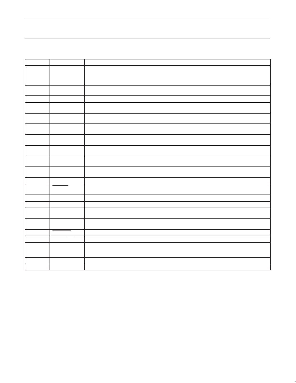
PIN DESCRIPTION
PIN(S) SYMBOL FUNCTION
1, 2, 8, 9,
12, 18, 24,
25, 31, 37,
40
3, 4 48M_0/SELA
6 3V66 66 MHz clock: 66 MHZ reference clock
10, 11 HCLK0
13, 14 HCLK1
16, 17 HCLK2
47, 48 PCI0
39, 38 HCLK3
36, 35 HCLK4
33, 32 HCLK5
19 REF 3.3 V fixed 14.318 MHz output
20 SPREAD Enables spread spectrum mode when held LOW on differential host outputs, 3V66 and PCI clocks.
22 XIN Crystal input
23 XOUT Crystal output
26 I
29, 30 MULTSEL0
41 PWRDWN Device enters power-down mode when held LOW. Asserts LOW .
45 SEL133/100 Select input pin for enabling 133 MHz or 100 MHz CPU outputs
5, 7, 15,
21, 27, 28,
34, 46
43 V
42 V
V
DD
48M_1/SELB
HCLKB0
HCLKB1
HCLKB2
PCI1
HCLKB3
HCLKB4
HCLKB5
REF
MULTSEL1
V
SS
DDA
SSA
3.3 V power supply
Pins 9, 12, and 18 supply host output pairs 0, 1, and 2.
Pins 37 and 40 supply host output pairs 3, 4, and 5.
3.3 V fixed 48 MHz clock outputs. During power-up pins function as latched inputs that enable SELA and
SELB prior to the pins being used for output of 3 V at 48 MHz. Part must be clocked to latch data in.
Host output pair 0
Host output pair 1
Host output pair 2
33 MHz clocks: 33 MHz reference clocks
Host output pair 3
Host output pair 4
Host output pair 5
Asserts LOW.
This pin controls the reference current for the host pairs. This pin requires a fixed precision resistor tied to
ground in order to establish the correct current.
Select input pin used to control the scaling of the HCLK and HCLKB output current.
Ground
3.3 V power supply for analog circuits
Ground for analog circuits
2001 Oct 1 1
3
Philips Semiconductors Product data
CK00 (100/133 MHz) spread spectrum differential
system clock generator
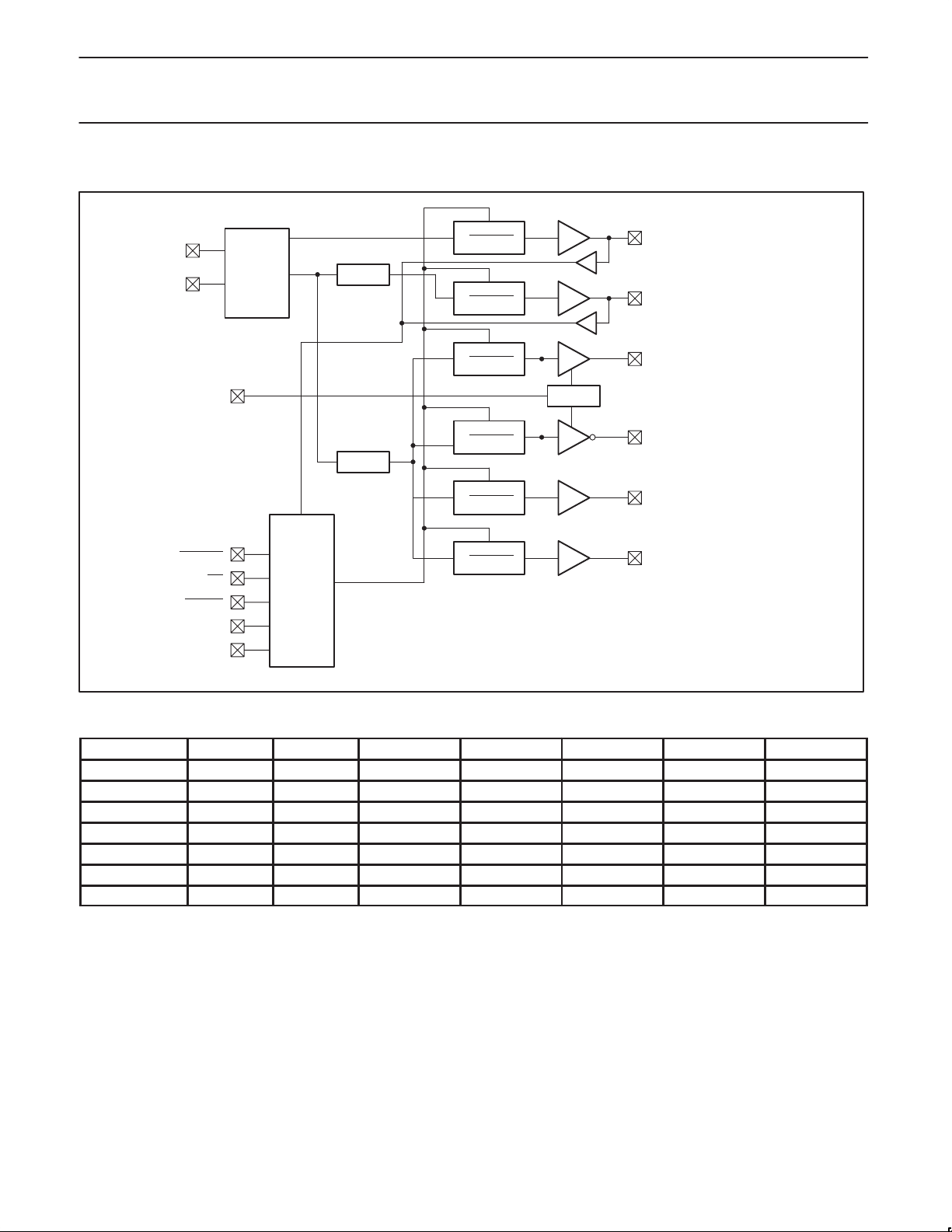
BLOCK DIAGRAM
XIN
XOUT
I
REF
14.318 MHz
OSC
USB PLL
SYS PLL
PWRDWN
PWRDWN
SELA/B
PWRDWN
PWRDWN
PWRDWN
PCK2021
REF[0] (14.318 MHz)
SELC
48MHz[0..1] (3 V)
HOST[0..5] (100/133 MHz)
IBIAS
HOST_BAR[0..5] (100/133 MHz)
PCI[0..1] (33 MHz)
PWRDWN
SEL133/100
SPREAD
MULTSEL0
MULTSEL1
PWRDWN
LOGIC
3V66[0] (66 MHz)
SW00961
FUNCTION TABLE
SEL100/133 SELA SELB HOST 48MHz PCI33MHz 66MHz REFCLK
0 0 0 100 MHz 48 MHz 33.3 MHz 66.7 MHz 14.3 MHz
0 0 1 100 MHz Disable/Low 33.3 MHz 66.7 MHz 14.3 MHz
0 1 0 100 MHz Disable/Low Disable/Low 66.7 MHz Disable/Low
0 1 1 Hi-Z Hi-Z Hi-Z Hi-Z Hi-Z
1 0 0 133 MHz 48 MHz 33.3 MHz 66.7 MHz 14.3 MHz
1 0 1 133 MHz Disable/Low 33.3 MHz 66.7 MHz 14.3 MHz
1 1 0 200 MHz 48 MHz 33.3 MHz 66.7 MHz 14.3 MHz
2001 Oct 1 1
4
Philips Semiconductors Product data
CK00 (100/133 MHz) spread spectrum differential
system clock generator
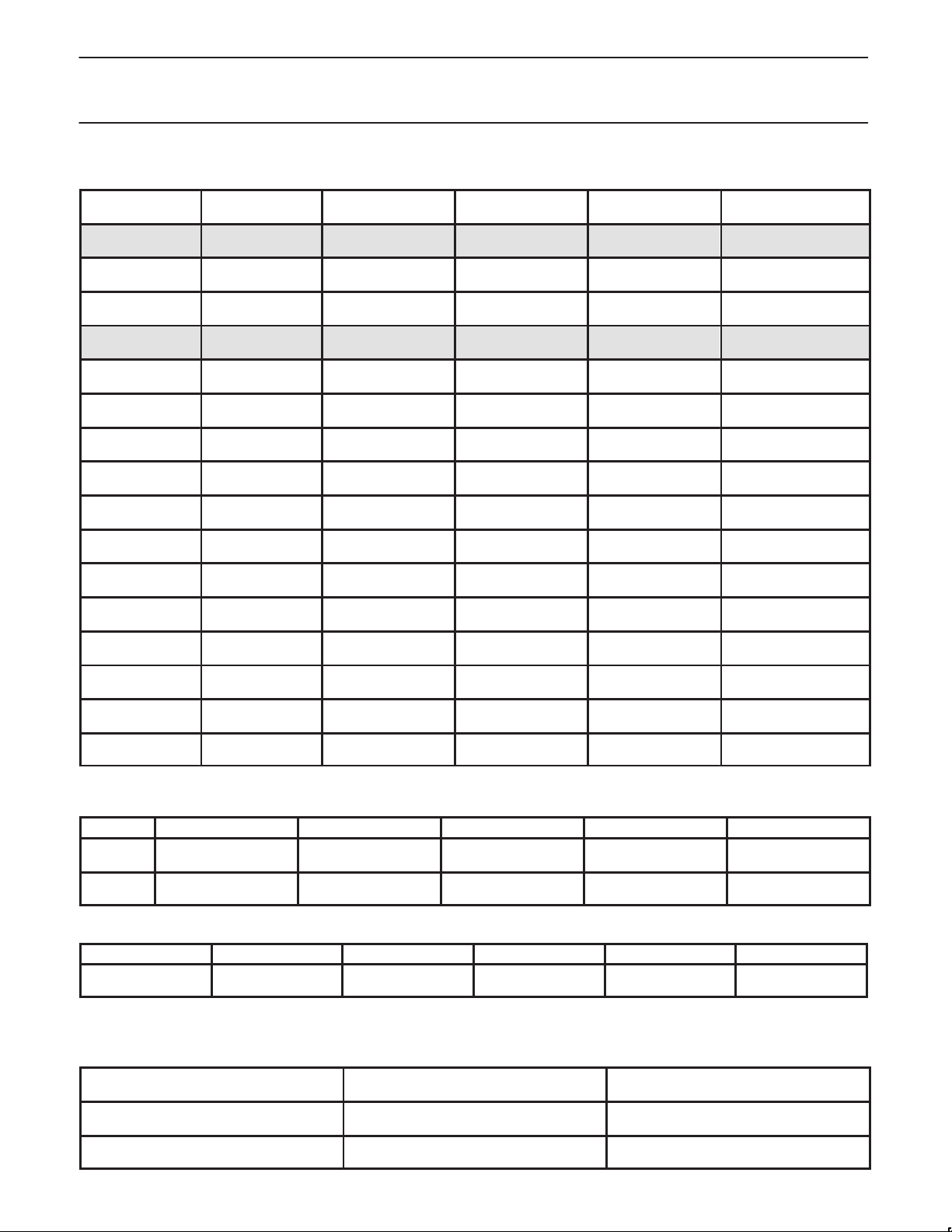
Table 1. Host swing select functions
MULTSEL0 MULTSEL1
0 0 60 Ω
0 0 50 Ω
0 1 60 Ω
0 1 50 Ω
1 0 60 Ω
1 0 50 Ω
1 1 60 Ω
1 1 50 Ω
0 0 30 Ω
0 0 25 Ω
0 1 30 Ω
0 1 25 Ω
1 0 30 Ω
1 0 25 Ω
1 1 30 Ω
1 1 25 Ω
NOTE:
The outputs are optimized for the configurations shown shaded.
BOARD
IMPEDANCE
R
I
R
I
R
I
R
I
R
I
R
I
R
I
R
I
R
R
R
R
R
R
R
R
REF
REF
REF
REF
REF
REF
REF
REF
REF
REF
REF
REF
REF
REF
REF
REF
REF
I
REF
I
REF
I
REF
I
REF
I
REF
I
REF
I
REF
I
REF
REF
REF
REF
REF
REF
REF
REF
I
REF
= 475 1%
= 2.32 mA
= 475 1%
= 2.32 mA
= 475 1%
= 2.32 mA
= 475 1%
= 2.32 mA
= 475 1%
= 2.32 mA
= 475 1%
= 2.32 mA
= 475 1%
= 2.32 mA
= 475 1%
= 2.32 mA
= 221 1%
= 5 mA
= 221 1%
= 5 mA
= 221 1%
= 5 mA
= 221 1%
= 5 mA
= 221 1%
= 5 mA
= 221 1%
= 5 mA
= 221 1%
= 5 mA
= 221 1%
= 5 mA
I
OH
IOH = 5*I
IOH = 5*I
IOH = 6*I
IOH = 6*I
IOH = 4*I
IOH = 4*I
IOH = 7*I
IOH = 7*I
IOH = 5*I
IOH = 5*I
IOH = 6*I
IOH = 6*I
IOH = 4*I
IOH = 4*I
IOH = 7*I
IOH = 7*I
REF
REF
REF
REF
REF
REF
REF
REF
REF
REF
REF
REF
REF
REF
REF
REF
PCK2021
VOH @ IREF = 2.32 mA
0.71 V
0.59 V
0.85 V
0.71 V
0.56 V
0.47 V
0.99 V
0.82 V
0.75 V
0.62 V
0.90 V
0.75 V
0.60 V
0.50 V
1.05 V
0.84 V
CONDITIONS CONFIGURATION LOAD MIN. MAX.
I
OUT
I
OUT
VDD = 3.3 V
VDD = 3.3 V ±5%
All combinations;
see Table 1 above
All combinations;
see Table 1 above
Nominal test load for
given configuration
Nominal test load for
given configuration
–7% of I
OH
see Table 1 above
–12% of I
see Table 1 above
OH
+7% of I
see Table 1 above
+12% of I
see Table 1 above
POWER-DOWN MODE
PWRDWN HCLK/HCLKB 3V66 PCI 48MHz REFCLK
Asserts LOW
0 = Active
Host = 2*I
Host_bar = undriven
REF
LOW LOW LOW LOW
NOTE:
The differential outputs should have a voltage forced across them when power-down is asserted.
SPREAD SPECTRUM FUNCTION
48 MHz PLL
REFCLK
No Spread
No Spread
2001 Oct 1 1
SPREAD # FUNCTION
1
0
Host, PCI, and 3V66
No Spread
Host, PCI, and 3V66
spread t0.5%
5
OH
OH
 Loading...