

Philips PCF1171CT Datasheet
INTEGRATED CIRCUITS
DATA SH EET
PCF1171C
4-digit LCD car clock
Product specification
Supersedes data of September 1993
File under Integrated Circuits, IC16
1997 Apr 16

Philips Semiconductors Product specification
4-digit LCD car clock PCF1171C
FEATURES
• Driving standard 31⁄2 or a 4-digit LCD
• Internal voltage regulator for 5 V LCD
• Option for external stabilized voltage supply
• 4.19 MHz oscillator
• Integrated oscillator output capacitor and polarization
resistor
• Operating ambient temperature: −40 to +85 °C
• 40-lead plastic SMD, face down (VSO40).
ORDERING INFORMATION
TYPE
NUMBER
PCF1171CT VSO40 plastic very small outline package; 40 leads; face down
PCF1171CU − uncased chip in tray
Notes
1. See Fig.1 and Chapter “Package outline” for pin layout and package details.
2. See Chapter “Chip dimensions and bonding pad locations” for pad layout and package details.
NAME DESCRIPTION VERSION
(2)
GENERAL DESCRIPTION
The PCF1171C is a single chip, 4.19 MHz CMOS car clock
circuit indicating hours and minutes. It is designed to drive
a 31⁄2 or 4-digit liquid crystal display (LCD).
Two external single-pole, single-throw switches will
accomplish all time setting functions. A bonding option
allows the selection of 12-hour or 24-hour display mode.
The circuit is battery-operated via an internal 5 V voltage
regulator or by an external stabilized voltage supply.
PACKAGE
(1)
SOT158-2
−
1997 Apr 16 2
Philips Semiconductors Product specification
4-digit LCD car clock PCF1171C
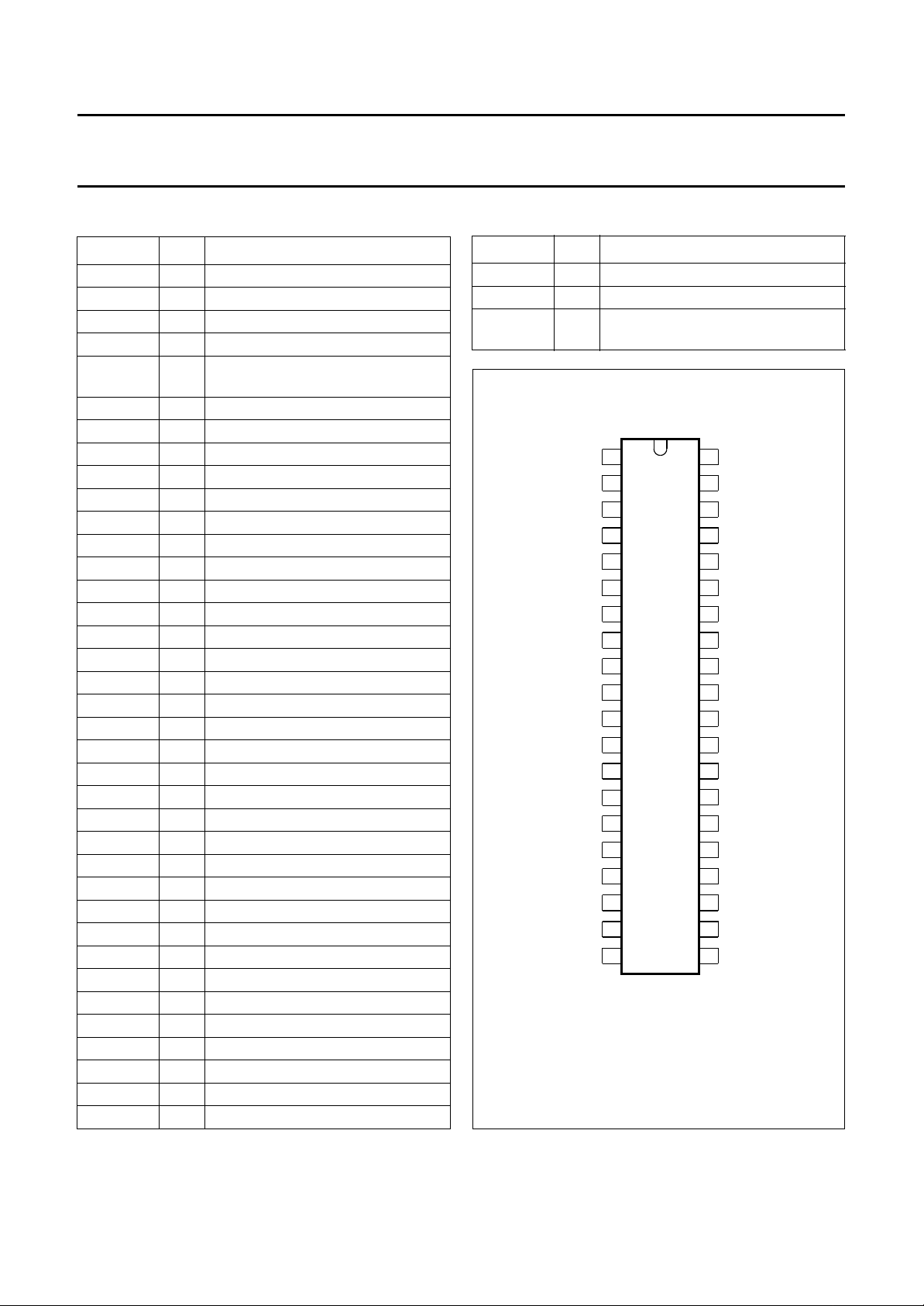
PINNING
SYMBOL PIN DESCRIPTION
OSC OUT 1 oscillator output
OSC IN 2 oscillator input
S1 3 set hour
S3 4 ±2 minute correction
BP 5 64 Hz backplane driver
(common of LCD)
ADEG1 6 segment driver
C1 7 segment driver
E2 8 segment driver
D2 9 segment driver
C2 10 segment driver
E3 11 segment driver
D3 12 segment driver
C3 13 segment driver
E4 14 segment driver
D4 15 segment driver
C4 16 segment driver
B4 17 segment driver
S2 18 set minutes
S4 19 internal voltage regulation
V
SS
20 negative supply
S6 21 selectable correction mode
S5 22 12/24-hour mode
V
DD
23 positive supply
A4 24 segment driver
F4 25 segment driver
G4 26 segment driver
B3 27 segment driver
A3 28 segment driver
F3 29 segment driver
G3 30 segment driver
P1, P2 31 colon flashing
P3, P4 32 colon static
B2 33 segment driver
A2 34 segment driver
F2 35 segment driver
G2 36 segment driver
B1 37 segment driver
SYMBOL PIN DESCRIPTION
TR 38 test reset; connect to (VDD)
TS 39 test speed-up; connect to (V
) 40 positive supply for test and oscillator
(V
DD
inputs
OSC OUT
OSC IN
S1
S3
BP
ADEG1
C1
E2
D2
C2
E3
D3
C3
E4
D4
C4
B4
S2
S4
V
SS
1
2
3
4
5
6
7
8
9
10
PCF1171CT
11
12
13
15
16
17
18
19
20
MSA981
(V )
40
DD
39
TS
38
TR
37
B1
36
G2
35
F2
34
A2
33
B2
32
P3, P4
31
P1, P2
30
G3
29
F3
28
A3
2714
B3
26
G4
25
F4
24
A4
V
23
DD
22
S5
21
S6
Fig.1 Pin configuration, PCF1171CT, (VSO40).
DD
)
1997 Apr 16 3
Philips Semiconductors Product specification
4-digit LCD car clock PCF1171C
F1
E1
TIME
A1
G1
D1
A2
B1
C1
F2
E2
G2
D2
B2
C2
P1 (P3)
P2 (P4)
F3
E3
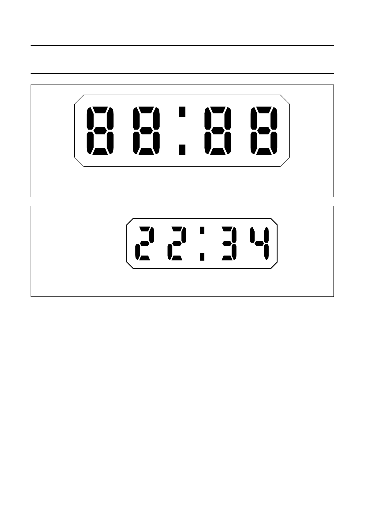
Fig.2 Segment designation of LCD.
Fig.3 Display mode (24-hour mode shown).
A3
G3
D3
B3
C3
F4
E4
A4
G4
D4
MSA985
B4
C4
MSA984
OPERATIONAL INPUTS
Operational inputs S1, S2 and S3 have an internal pull-up
resistor to facilitate use of external single-pole,
single-throw switches. A specific debounce circuit is
integrated as protection against contact debounce and
parasitic voltages.
In the description below, an arrangement as shown in
Fig.5 is assumed and S1, S2 and S3 refer to the external
switches rather than the corresponding inputs.
Set hours, switch S1
Closure of S1 increments the hours according to the
correction mode selected by S6 (see Chapter
“Input options”).
1997 Apr 16 4
Set minutes/reset seconds, switch S2
When S2 is closed, the minute setting is corrected
according to the correction mode determined by S6 (see
Chapter “Input options”).
The seconds counter is reset to zero each time S2 is
closed, and begins running each time S2 is opened.
Segment test/reset, switches S1 and S2
If S1 and S2 are closed simultaneously all LCD segments
are switched on. When the switches are released, the
clock starts at 1 : 00 in the 12-hour mode or 0 : 00 in the
24-hour mode.
Philips Semiconductors Product specification
4-digit LCD car clock PCF1171C
Time correction ±2 minutes, switch S3
This switch operates in two ranges:
• Displayed time ≥ 58 minutes 00 seconds
• Displayed time ≤ 1 minute 59 seconds.
When switch S3 is pressed in these ranges, the minutes
and seconds are reset to zero. For displayed
time ≥ 58 minutes 00 seconds, the hour is also
incremented by one.
INPUT OPTIONS
In the description below S4, S5 and S6 refer to the external
switches shown in Fig.5 rather than to the corresponding
inputs.
In a real application, these inputs will normally be bonded
to the appropriate level to give the required function mode.
Internal/external regulation, switch S4
For internal regulation, S4 is closed, the internal voltage
regulator is active and the voltage supply for the LCD is
regulated to 5 V. For external regulation, S4 is open and
the circuit has to be supplied with an externally regulated
voltage.
12/24-hour mode, switch S5
For 12-hour display mode, S5 is connected to VDD.
For 24-hour display mode, S5 is connected to VSS.
Single/continuous correction mode, switch S6
For single-set correction mode, S6 is connected to V
DD
.
Each closure of S1 or S2 advances the counter by one.
For continuous-set correction mode, S6 is connected to
VSS. Momentary closure of S1 or S2 causes single
increments as for single-set correction mode. If S1 or S2 is
kept closed for more than 1s, the counter is automatically
incremented by 1 for each full second that S1 or S2 is kept
closed.
TESTING
In normal operation the test inputs TR (pin 38) and TS
(pin 39) have to be connected to V
(pin 23). A test
DD
frequency (64 Hz) is available at BP (pin 5). The test mode
is activated by connecting TS to VSS (pin 20). All output
frequencies are then increased by a factor of 65536.
In this mode the maximum input frequency is 100 kHz
(external generator at OSC IN). By connecting TR to V
SS
all counters (seconds, minutes and hours) are stopped.
After connecting TR to VDD all counters start from an initial
state.
The switches/inputs described above also operate in the
test mode.
LIMITING VALUES
In accordance with the Absolute Maximum Rating System (IEC 134).
SYMBOL PARAMETER CONDITIONS MIN. MAX. UNIT
V
DD
supply voltage with respect to VSS with internal
note 1 − 8V
regulation disconnected;
V
I
T
amb
T
stg
all input voltages VSS− 0.3 VDD+ 0.3 V
operating ambient temperature −40 +85 °C
storage temperature −55 +125 °C
Note
1. Connecting the supply voltage with reverse polarity, will not harm the circuit, provided the current is limited to 10 mA
by the external resistor.
HANDLING
Inputs and outputs are protected against electrostatic discharges in normal handling. However, to be totally safe, it is
advisable to take handling precautions appropriate to handling MOS devices. Advice can be found in
“Data Handbook IC16, General, Handling MOS Devices”
.
1997 Apr 16 5
 Loading...