

Page 1
PageWriter TC Cardiograph
Network Configuration Guide
Page 2

Notice
About This Edition
Published by Philips
Medical Systems
Printed in USA
Publication number
453564114441
Edition History
Edition 1, August 2008
Software Revision
A.01.00 and higher
Edition 2, September 2010
Software Revision
A.04.01 and higher
Warranty
Philips Medical Systems
reserves the right to make
changes to both this
Network Configuration
Guide and to the product
that it describes. Product
specifications are subject
to change without notice.
Nothing contained within
this Network Configura-
tion Guide is intended as
any offer, warranty,
promise, or contractual
condition, and must not be
taken as such.
Copyright
©2010 Koninklijke
Philips Electronics N.V.
All rights are reserved. All
other product names are
the property of their
respective owners.
Reproduction in whole or
in part in any form, or by
any means, electrical,
mechanical or otherwise,
is prohibited without the
written consent of the
copyright holder.
Philips Medical Systems
3000 Minuteman Road
Andover, MA 01810 USA
(978) 687-1501
Unauthorized copying of
this publication may not
only infringe copyright
laws, but may also reduce
the ability of Philips
Medical Systems to
provide accurate and
current information to
users.
Compliance
The Philips Medical
Systems PageWriter
TC70, TC50, and TC30
cardiographs comply with
all relevant international
and national standards and
laws. Information on
compliance will be
supplied on request by a
local Philips Medical
Systems representative, or
by the manufacturer.
Intended Use of this
Network Configuration Guide
This Philips product is
intended to be operated
only in accordance with
the safety procedures and
operating instructions
provided in this Network
Configuration Guide, and
in accordance with the
purposes for which it was
designed. Installation, use,
and operation of this
product is subject to the
laws in effect in the jurisdiction(s) in which the
product is being used.
Users must only install,
use, and operate this
product in such a manner
that does not conflict with
applicable laws or regulations that have the force of
law. Use of this product
for purposes other than the
express intended purpose
provided by the manufacturer, or incorrect use and
operation, may relieve the
manufacturer (or agent)
from all or some responsibility for resultant noncompliance, damage, or
injury.
United States federal law
restricts this device to use
by or on the order of a
physician. THIS
PRODUCT IS NOT
INTENDED FOR HOME
USE.
Training
Users of this product must
receive adequate clinical
training on its safe and
effective use before
attempting to operate the
product as described in
this Network Configura-
tion Guide.
Training requirements
vary by country. Users
must ensure that they
receive adequate clinical
training in accordance
with local laws or regulations.
For further information on
available training on the
use of this product, please
contact a Philips Medical
Systems representative, or
the manufacturer.
Medical Device
Directive
The PageWriter TC70,
TC50 and TC30 cardiographs comply with the
requirements of the
Medical Device Directive
93/42/EEC and carries the
mark accordingly.
0123
Authorized EU-representative:
Philips Medizin Systeme
Böblingen GmbH
Hewlett Packard Str. 2
71034 Böblingen
Germany
Page 3

Contents
Chapter 1 Overview of Workflow Options
TraceMaster with OrderVue Workflow . . . . . . . . . . . . . . . . . . . . . . . . . . . . . . . . . . . . . . . . 1-1
ECG PDF Export and Remote PC Workflow . . . . . . . . . . . . . . . . . . . . . . . . . . . . . . . . . . . . 1-2
ECG Fax Workflow . . . . . . . . . . . . . . . . . . . . . . . . . . . . . . . . . . . . . . . . . . . . . . . . . . . . . . . . 1-3
Special Notes About Fax Transmission . . . . . . . . . . . . . . . . . . . . . . . . . . . . . . . . . . . . . . 1-3
Third Party ECG Management System Workflow . . . . . . . . . . . . . . . . . . . . . . . . . . . . . . . . . 1-4
Using the Cardiograph Setup Screens . . . . . . . . . . . . . . . . . . . . . . . . . . . . . . . . . . . . . . . . . . 1-5
Philips ECG XML Information. . . . . . . . . . . . . . . . . . . . . . . . . . . . . . . . . . . . . . . . . . . . . . . . . 1-7
Using the Philips InCenter Site . . . . . . . . . . . . . . . . . . . . . . . . . . . . . . . . . . . . . . . . . . . . . . . . 1-8
About Adobe Acrobat Versions . . . . . . . . . . . . . . . . . . . . . . . . . . . . . . . . . . . . . . . . . . . 1-8
Using Setup Help. . . . . . . . . . . . . . . . . . . . . . . . . . . . . . . . . . . . . . . . . . . . . . . . . . . . . . . . . . . 1-9
Contacting a Philips Response Center . . . . . . . . . . . . . . . . . . . . . . . . . . . . . . . . . . . . . . . . . 1-10
North America Response Centers . . . . . . . . . . . . . . . . . . . . . . . . . . . . . . . . . . . . . 1-10
South America Response Centers. . . . . . . . . . . . . . . . . . . . . . . . . . . . . . . . . . . . . . 1-10
Europe Response Centers . . . . . . . . . . . . . . . . . . . . . . . . . . . . . . . . . . . . . . . . . . . . 1-11
Europe Response Centers . . . . . . . . . . . . . . . . . . . . . . . . . . . . . . . . . . . . . . . . . . . . 1-12
Asia Response Centers . . . . . . . . . . . . . . . . . . . . . . . . . . . . . . . . . . . . . . . . . . . . . . 1-13
Africa and Middle East . . . . . . . . . . . . . . . . . . . . . . . . . . . . . . . . . . . . . . . . . . . . . . . 1-14
Chapter 2 Configuring Network Connectivity
About Network Settings. . . . . . . . . . . . . . . . . . . . . . . . . . . . . . . . . . . . . . . . . . . . . . . . . . . . . 2-1
Network Connection Status Window. . . . . . . . . . . . . . . . . . . . . . . . . . . . . . . . . . . . . . . 2-1
About the Refresh Button . . . . . . . . . . . . . . . . . . . . . . . . . . . . . . . . . . . . . . . . . . . . . 2-2
Obtaining a New IP Address for the Cardiograph . . . . . . . . . . . . . . . . . . . . . . . . . . 2-2
Obtaining the IP Address Automatically (Using DHCP) . . . . . . . . . . . . . . . . . . . . . . . . . 2-3
About Auto Negotiation . . . . . . . . . . . . . . . . . . . . . . . . . . . . . . . . . . . . . . . . . . . . . . . . . 2-3
Specifying IP Address (Fixed IP) . . . . . . . . . . . . . . . . . . . . . . . . . . . . . . . . . . . . . . . . . . . . 2-3
Checking the Cardiograph IP Address. . . . . . . . . . . . . . . . . . . . . . . . . . . . . . . . . . . . . . . 2-3
Configuring Multiple Cardiographs . . . . . . . . . . . . . . . . . . . . . . . . . . . . . . . . . . . . . . . . . 2-4
Configuring Cardiograph Network Settings. . . . . . . . . . . . . . . . . . . . . . . . . . . . . . . . . . . . . . 2-4
Configuring Wired LAN (Ethernet) Settings . . . . . . . . . . . . . . . . . . . . . . . . . . . . . . . . . . 2-6
Configuring Manual Ethernet Settings . . . . . . . . . . . . . . . . . . . . . . . . . . . . . . . . . . . . 2-8
About Wireless LAN Settings . . . . . . . . . . . . . . . . . . . . . . . . . . . . . . . . . . . . . . . . . . . . . 2-9
Other Resources and Information . . . . . . . . . . . . . . . . . . . . . . . . . . . . . . . . . . . . . . 2-9
Supported Security Options . . . . . . . . . . . . . . . . . . . . . . . . . . . . . . . . . . . . . . . . . . . 2-9
Configuring Wireless LAN Settings . . . . . . . . . . . . . . . . . . . . . . . . . . . . . . . . . . . . . . . . 2-12
Before You Begin . . . . . . . . . . . . . . . . . . . . . . . . . . . . . . . . . . . . . . . . . . . . . . . . . . . 2-13
Installing the Wireless LAN Card and Cover . . . . . . . . . . . . . . . . . . . . . . . . . . . . . 2-13
About Authentication Certificates and Private Keys . . . . . . . . . . . . . . . . . . . . . . . 2-15
Contents-1
Page 4

Table of Contents
Loading Authentication Certificates . . . . . . . . . . . . . . . . . . . . . . . . . . . . . . . . . . . . .2-16
Configuring Wireless Adapter Settings . . . . . . . . . . . . . . . . . . . . . . . . . . . . . . . . . . .2-19
Selecting the Active Profile . . . . . . . . . . . . . . . . . . . . . . . . . . . . . . . . . . . . . . . . . . . .2-25
Wireless LAN Connectivity Indicator. . . . . . . . . . . . . . . . . . . . . . . . . . . . . . . . . . . .2-26
Testing the Network or Modem Connection . . . . . . . . . . . . . . . . . . . . . . . . . . . . . . . . . . . .2-26
Chapter 3 Configuring TraceMaster ECG Management System
Settings
About Configuring TraceMaster Connections . . . . . . . . . . . . . . . . . . . . . . . . . . . . . . . . . . . . .3-2
About Supported TraceMaster Versions and Compatibility. . . . . . . . . . . . . . . . . . . . . . .3-2
About TraceMaster Supported Extended Lead Configurations . . . . . . . . . . . . . . . . . . . .3-8
About Security . . . . . . . . . . . . . . . . . . . . . . . . . . . . . . . . . . . . . . . . . . . . . . . . . . . . . . . . . .3-9
Configuring a TraceMaster Connection . . . . . . . . . . . . . . . . . . . . . . . . . . . . . . . . . . . . . . . . . .3-9
Configuring a Network TraceMaster Connection . . . . . . . . . . . . . . . . . . . . . . . . . . .3-9
Configuring a TraceMaster Connection with the Modem . . . . . . . . . . . . . . . . . . . .3-13
Testing the TraceMaster Connection . . . . . . . . . . . . . . . . . . . . . . . . . . . . . . . . . . . .3-16
Setting the Default TraceMaster Server . . . . . . . . . . . . . . . . . . . . . . . . . . . . . . . . . .3-17
Specifying Time Synchronization Settings . . . . . . . . . . . . . . . . . . . . . . . . . . . . . . . . .3-18
Editing TraceMaster Connection Settings . . . . . . . . . . . . . . . . . . . . . . . . . . . . . . . . . . . . . . .3-20
Chapter 4 Configuring OrderVue Settings
About OrderVue Workflow. . . . . . . . . . . . . . . . . . . . . . . . . . . . . . . . . . . . . . . . . . . . . . . . . . .4-1
OrderVue Configuration Overview . . . . . . . . . . . . . . . . . . . . . . . . . . . . . . . . . . . . . . . . . . . . .4-2
Before You Begin . . . . . . . . . . . . . . . . . . . . . . . . . . . . . . . . . . . . . . . . . . . . . . . . . . . . . . . . . . .4-3
Creating an OrderVue Worklist . . . . . . . . . . . . . . . . . . . . . . . . . . . . . . . . . . . . . . . . . . . . . . .4-3
Testing Order Worklist Settings . . . . . . . . . . . . . . . . . . . . . . . . . . . . . . . . . . . . . . . . . . . .4-8
Setting General OrderVue Options . . . . . . . . . . . . . . . . . . . . . . . . . . . . . . . . . . . . . . . . . . . .4-10
Editing Worklist Settings. . . . . . . . . . . . . . . . . . . . . . . . . . . . . . . . . . . . . . . . . . . . . . . . . . . . .4-11
Chapter 5 Configuring PDF Export and Remote PC Settings
TC Cardiograph PDF Export and Remote PC Features . . . . . . . . . . . . . . . . . . . . . . . . . . . . .5-1
About Log Files. . . . . . . . . . . . . . . . . . . . . . . . . . . . . . . . . . . . . . . . . . . . . . . . . . . . . . . . . .5-1
Configuration Overview. . . . . . . . . . . . . . . . . . . . . . . . . . . . . . . . . . . . . . . . . . . . . . . . . . .5-1
Configuring a PDF Export and Remote PC Connection . . . . . . . . . . . . . . . . . . . . . . . . . . . . .5-2
Editing Settings . . . . . . . . . . . . . . . . . . . . . . . . . . . . . . . . . . . . . . . . . . . . . . . . . . . . . . . . . . . . .5-3
Transmitting ECGs as PDF Files from the Archive . . . . . . . . . . . . . . . . . . . . . . . . . . . . . . . . .5-3
Transmitting or Receiving Log and Custom Setting Files . . . . . . . . . . . . . . . . . . . . . . . . . . . .5-4
Contents-2 PageWriter TC Cardiograph Network Configuration Guide
Page 5

Table of Contents
Chapter 6 Configuring Third Party ECG Management System
Settings
About Configuring Third Party (non-Philips) Connections . . . . . . . . . . . . . . . . . . . . . . . . . . 6-2
About Philips ECG XML Versions . . . . . . . . . . . . . . . . . . . . . . . . . . . . . . . . . . . . . . . . . . 6-2
About Security . . . . . . . . . . . . . . . . . . . . . . . . . . . . . . . . . . . . . . . . . . . . . . . . . . . . . . . . . 6-3
Configuring a Third Party ECG System Connection . . . . . . . . . . . . . . . . . . . . . . . . . . . . . . . 6-4
Configuring a Network Third Party Connection . . . . . . . . . . . . . . . . . . . . . . . . . . . . . . 6-4
Configuring a Third Party Modem Connection . . . . . . . . . . . . . . . . . . . . . . . . . . . . . . . . 6-7
Setting the Default Server . . . . . . . . . . . . . . . . . . . . . . . . . . . . . . . . . . . . . . . . . . . . . . . . 6-9
Testing the Third Party Connection . . . . . . . . . . . . . . . . . . . . . . . . . . . . . . . . . . . . . . . 6-10
Editing Third Party Settings. . . . . . . . . . . . . . . . . . . . . . . . . . . . . . . . . . . . . . . . . . . . . . . . . . 6-11
Chapter 7 Configuring FAX Settings
Special Notes About Fax Transmission . . . . . . . . . . . . . . . . . . . . . . . . . . . . . . . . . . . . . . 7-1
Before You Begin . . . . . . . . . . . . . . . . . . . . . . . . . . . . . . . . . . . . . . . . . . . . . . . . . . . . . . . 7-1
Creating a Fax Recipient. . . . . . . . . . . . . . . . . . . . . . . . . . . . . . . . . . . . . . . . . . . . . . . . . . 7-1
Editing a Fax Recipient . . . . . . . . . . . . . . . . . . . . . . . . . . . . . . . . . . . . . . . . . . . . . . . . . . . 7-3
Chapter 8 Troubleshooting Communication Issues
Troubleshooting a Wired Connection . . . . . . . . . . . . . . . . . . . . . . . . . . . . . . . . . . . . . . . . . . 8-1
Troubleshooting a Wireless Connection . . . . . . . . . . . . . . . . . . . . . . . . . . . . . . . . . . . . . . . . 8-2
Additional Troubleshooting Information . . . . . . . . . . . . . . . . . . . . . . . . . . . . . . . . . . . . . . . . 8-4
TraceMaster ECG Management System Issues . . . . . . . . . . . . . . . . . . . . . . . . . . . . . . . . 8-4
OrderVue Issues . . . . . . . . . . . . . . . . . . . . . . . . . . . . . . . . . . . . . . . . . . . . . . . . . . . . . . . 8-6
TraceMaster Remote Query Issues . . . . . . . . . . . . . . . . . . . . . . . . . . . . . . . . . . . . . . . . 8-8
Archive Screen Issues . . . . . . . . . . . . . . . . . . . . . . . . . . . . . . . . . . . . . . . . . . . . . . . . . . 8-10
Restarting the Cardiograph. . . . . . . . . . . . . . . . . . . . . . . . . . . . . . . . . . . . . . . . . . . . . . . . . . 8-16
Index
PageWriter TC Cardiograph Network Configuration Guide Contents-3
Page 6

Table of Contents
Contents-4 PageWriter TC Cardiograph Network Configuration Guide
Page 7

1About the Network Configuration
Guide
This PageWriter TC Cardiograph Network Configuration Guide is intended to assist with
configuring network or modem connectivity between Philips PageWriter TC cardiographs and
external order and ECG management systems.
Before attempting to operate the products described in this document, read this Network
Configuration Guide, and the applicable PageWriter TC Cardiograph Instructions for Use.
Note and strictly observe all Warning and Cautions as described in this document, and in the
PageWriter TC Cardiograph Instructions for Use.
Pay special attention to all warning and caution statements included in this document.
WARNING Warning statements describe conditions or actions that may result in a potentially
serious outcome, adverse event, or a safety hazard. Failure to follow a Warning may
result in death or serious injury to the user or to the patient.
CAUTION Caution statements describe when special care is necessary for the safe and effective use of the
product. Failure to follow a caution may result in minor to moderate personal injury or damage to the
product or other property, a remote risk of more serious injury, or may cause environmental
pollution.
NOTE Notes contain additional important information about a topic.
TIP A Tip contains suggested information on using a particular feature.
Menu items and button names appear in bold no-serif font. Example: Touch the Setup button.
PageWriter TC Cardiograph Network Configuration Guide i
Page 8

ii PageWriter TC Cardiograph Network Configuration Guide
Page 9

1
1Overview of Workflow Options
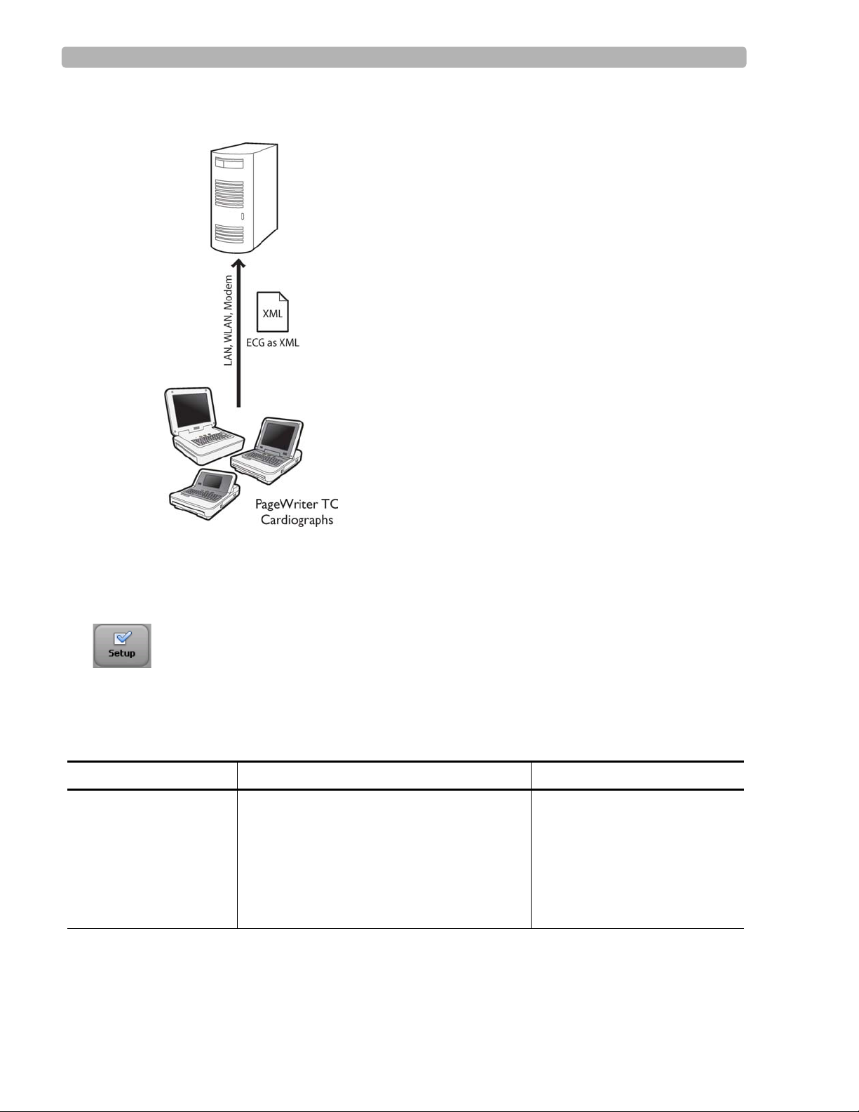
The PageWriter TC cardiographs can communicate over a wireless LAN, Ethernet LAN, or
modem with a Philips TraceMaster ECG Management System for an integrated order and
ECG management workflow solution. Enabling cardiograph connectivity with a TraceMaster
server allows for the direct downloading of pending patient orders to the cardiograph, and for
the subsequent uploading back to TraceMaster of the completed orders and associated ECGs
for reconciliation, review, and processing. With TraceMaster, you can also enable the Last
ECG and interactive query features on the cardiograph so that you can download ECGs
directly from a TraceMaster server, allowing for the on-screen review, printing, and
comparison of the most recent patient ECG directly at the cardiograph. The cardiograph can
also be configured to transmit completed ECGs to any third party (non-Philips) ECG
management system using a LAN, wireless LAN, or modem connection, and can be
configured to transmit completed ECGs as a fax transmission using the modem. The
cardiograph also supports the transmission of completed ECGs as a PDF file directly to any
remote networked PC or server.
For more information on purchasing any of the optional cardiograph features described in this
document (LAN, wireless LAN, modem/fax, orders), consult your Philips sales
representative, or your local dealer or distributor.
The following sections provide an overview of the supported ECG, order, fax, and PDF
workflow solutions available on the cardiograph, with references to the applicable
configuration instructions.
TraceMaster with OrderVue Workflow
The cardiograph can be configured to communicate with a TraceMaster ECG Management
System over a LAN, wireless LAN, or modem connection for a comprehensive bidirectional
orders, and ECG workflow management solution. In this workflow option, the TraceMaster
ECG Management System server receives orders and, as an option, ADT patient demographic
updates to existing orders, directly from a HIS in HL7 format. The system then converts the
order into an XML-based order format compatible with the PageWriter TC cardiograph.
Orders are then selected from the cardiograph Worklist at the beginning of each patient
session. Completed ECGs are then transferred back to the TraceMaster server for review and
reconciliation, with billing information transferred directly back to the HIS. For information
on configuring connectivity with a TraceMaster ECG Management System with the OrderVue
order handling option, see “Configuring TraceMaster ECG Management System Settings” on
page 3-1.
NOTE The ADT option available with OrderVue only provides for ADT updates to an existing HL7 patient
order received from the HIS.
1-1
Page 10
Overview of Workflow Options ECG PDF Export and Remote PC Workflow
Figure 1-1 TraceMaster with OrderVue Workflow
ECG PDF Export and Remote PC Workflow
The cardiograph can be configured to export ECGs as PDF files to any networked remote PC
or server using a LAN, or wireless LAN connection. The ECG PDF files may then be viewed
in PDF viewer software directly at the remote receiving PC or server. The remote PC or server
can also be configured to support the receipt of custom configuration files, or System Log files
from the cardiograph, and the remote server can transmit custom configuration files or
software update files directly to a cardiographs, accelerating the configuration and software
update processes. For more information on configuring PDF Export or Remote PC settings,
see “Configuring PDF Export and Remote PC Settings,” on page 5-1.
NOTE The ECG PDF Export and Remote PC workflow does not support the use of modem transmission.
1-2 PageWriter TC Cardiograph Network Configuration Guide
Page 11
Overview of Workflow Options ECG Fax Workflow
Figure 1-2 ECG PDF Export and Remote PC Workflow
ECG Fax Workflow
The cardiograph can be configured to fax completed ECGs to any remote receiving fax
machine using the optional modem. For more information on configuring the cardiograph
modem to fax ECGs, see “Configuring FAX Settings” on page 7-1.
Special Notes About Fax Transmission
CAUTION No guarantee is made as to the suitability of a faxed ECG for any particular purpose, due to the
variability inherent in fax technology.
CAUTION Faxed ECGs should only be sent to secure recipient fax machines.
PageWriter TC Cardiograph Network Configuration Guide 1-3
Page 12
Overview of Workflow Options Third Party ECG Management System Workflow
Figure 1-3 ECG Fax Transmission Workflow
Third Party ECG Management System Workflow
The cardiograph can be configured to transmit completed ECGs in a specified Philips XML
format to any remote receiving server using a modem, LAN, or wireless LAN connection. For
information on the Philips ECG XML Schema, see “Philips ECG XML Information” on
page 1-7. For information on configuring cardiograph connectivity with a third party (nonPhilips) ECG management system, see “Configuring Third Party ECG Management System
Settings” on page 6-1.
1-4 PageWriter TC Cardiograph Network Configuration Guide
Page 13
Overview of Workflow Options Using the Cardiograph Setup Screens
Figure 1-4 PageWriter TC Cardiograph to Third Party (non-Philips) ECG
Management System Transmission Workflow
Using the Cardiograph Setup Screens
All cardiograph networking and remote server settings, including TraceMaster or third party
ECG management system settings, are accessed through the Configuration Setup and Service
Utilities Menu. This menu is organized as described in Table 1-1. Touch
(bottom of screen) to open the menu, and then touch a button to make a selection from the
menu. Each menu selection is then organized into a series of buttons and tabs that appear at the
top of the screen. Touch a button or tab to select it. A selected button or tab appears
highlighted in blue.
Table 1-1 Configuration Setup and Service Utilites Main Menu Options
Menu Selection Features For details, see ...
Configure Cardiograph
Default Settings
Exams, Patient ID, Algorithm/Pacing,
Institution, Password, Filter, Locale, Power
Save/System, Save/Load Settings
Use the Help system on the
Setup screens for assistance in
specifying these clinical default
settings. For information on
using the Help system, see
“Using Setup Help” on
page 1-9.
Setup on the toolbar
PageWriter TC Cardiograph Network Configuration Guide 1-5
Page 14

Overview of Workflow Options Using the Cardiograph Setup Screens
Table 1-1 Configuration Setup and Service Utilites Main Menu Options (continued)
Menu Selection Features For details, see ...
Configure ECG
Network Settings,
LAN/WLAN
Configure ECG
Network Settings, ECG
Mgmt Systems
Wire Network
Use this tab to define Ethernet
connection and modem (available as an
option) settings for the cardiograph.
Wireless Network (available as an option)
Use this tab to define wireless connection
settings for the cardiograph, including
specifying settings in the Summit WLAN
Adapter utility.
Create TraceMaster Connection
Use this tab to configure a new
TraceMaster, or third party (non-Philips)
server connection, including
compression and encryption options.
Use this tab to configure remote PC or
server settings for the purposes of
transmitting PDF files, Log files, and
custom configuration files from the
cardiograph to a remote receiving PC or
server, and for transmitting custom
configuration files and software updates
from the networked PC or server to the
cardiograph.
“Configuring Wired LAN
(Ethernet) Settings” on page 2-
6.
“Configuring Wireless LAN
Settings” on page 2-12.
“Configuring a
TraceMaster Connection”
on page 3-9.
“Configuring Third Party
ECG Management System
Settings” on page 6-1.
“Configuring PDF Export
and Remote PC Settings”
on page 5-1.
Edit/Delete TraceMaster Connection
Use this tab to change or to delete
existing TraceMaster , third party, or PDF
export server settings, specify a default
server connection, enable Time Sync
feature, or to manually change the date
and time.
OrderVue Settings
Create OrderVue Inbox
Use this tab to create new OrderVue
Worklists for direct order download to
the cardiograph.
Edit/Delete OrderVue Inbox
Use this tab to change or to delete an
existing OrderVue Worklist.
1-6 PageWriter TC Cardiograph Network Configuration Guide
“Configuring OrderVue
Settings” on page 4-1.
Page 15

Overview of Workflow Options Philips ECG XML Information
Table 1-1 Configuration Setup and Service Utilites Main Menu Options (continued)
Menu Selection Features For details, see ...
Configure ECG
Network Settings, ECG
Mgmt Systems
Configure ECG
Network Settings, FAX
Service Utilities
ADT Settings
Create ADT Inbox
Notes: this feature is not supported on
PageWriter TC cardiographs with installed
software version A.04.04 and lower.
This ADT option is not used with OrderVue with
the ADT option installed. If using OrderVue with
the ADT option, you configure an OrderVue
(not ADT) Worklist.
Note: The Fax feature is only available with the
optional modem.
Create a Fax Recipient
Use this tab to create a new fax recipient,
including recipient name, number, and a
fax cover sheet.
Edit/Delete Fax Recipient
Use this tab to change or to delete an
existing fax entry.
Provides an overview of all cardiograph
operating information, and includes a set of
diagnostic tests and utilities that can be used
for troubleshooting purposes. Displays
system error and event log in real time for
immediate review.
“Configuring OrderVue
Settings” on page 4-1.
“Configuring FAX Settings” on
page 7-1.
PageWriter TC Cardiograph
Service Manual, available for
download from the Philips
InCenter site. For information,
see “Using the Philips InCenter
Site” on page 1-8.
Philips ECG XML Information
The PageWriter TC cardiographs export ECG data in XML (Extensible Markup Language)
format. There are three available XML schema versions on the cardiograph: version 1.03,
version 1.04, and version 1.04.01. Version 1.03 exports ECG data in 12-lead format only,
version 1.04 exports ECG data for up to 16 leads, and version 1.04.01 exports ECG data for up
to 16 leads and includes full interpretation from the Philips DXL Algorithm.
Information regarding the Philips ECG XML schema can be obtained directly from Philips
Medical Systems by sending an email request to:
name, facility, and the serial number of your PageWriter TC cardiograph in the email request.
PageWriter TC Cardiograph Network Configuration Guide 1-7
ecg@philips.com. Please include your
Page 16
Overview of Workflow Options Using the Philips InCenter Site
Using the Philips InCenter Site
The Philips InCenter site provides frequent updates to all Philips Cardiac Systems product
documentation and product software, including the PageWriter TC cardiographs.
The Philips InCenter site requires an active registration and password. To register, go to the
InCenter site at:
(located under the user login and password fields). On the following page, under
Updates
(lower right corner of page), click the Click here for account registration link. The
Cardiac Systems InCenter Registration page appears. Complete all of the information fields on
the page to receive a login and password for the InCenter site.
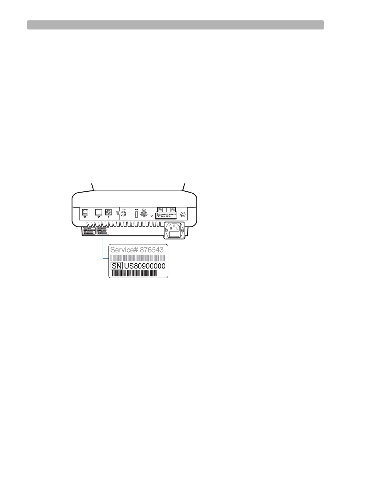
Registration for the InCenter site requires the serial number of at least one PageWriter TC
cardiograph in active use at your facility. The serial number is found on the product
identification label, located next to the text
the rear panel of the cardiograph, see Figure 1-5 on page 1-8.
Figure 1-5 Cardiograph Product Identification Label (rear view)
incenter.medical.philips.com and click on the Need help? link on the main page
Software
SN. The product identification label is located on
About Adobe Acrobat Versions
Adobe Acrobat Reader version 9.0 must be installed on the PC that is used to access the
Philips InCenter site. Previous versions of Acrobat Reader are not compatible with the Philips
InCenter site, and attempting to access InCenter with a previous version of Acrobat Reader
will result in error messages when opening documents. Uninstall all previous versions of
Acrobat Reader, and then proceed for a free install of Acrobat Reader 9.0 at:
Any version of Adobe Acrobat Professional or Acrobat Elements are also not compatible with
the Philips InCenter site, and error messages will appear when opening documents with these
applications. Acrobat Reader 9.0 must be installed in addition to Acrobat Professional or
Acrobat Elements.
Follow this procedure when accessing documents on the Philips InCenter site.
To access documents on the Philips InCenter site:
Exit Acrobat Professional or Acrobat Elements (if open).
1
2 Start Acrobat Reader 9.0.
1-8 PageWriter TC Cardiograph Network Configuration Guide
www.adobe.com.
Page 17
Overview of Workflow Options Using Setup Help
A
3 Open Internet Explorer , and go to the Philips InCenter site. Keep Acrobat Reader 9.0 open
the entire time while accessing the InCenter site.
Using Setup Help
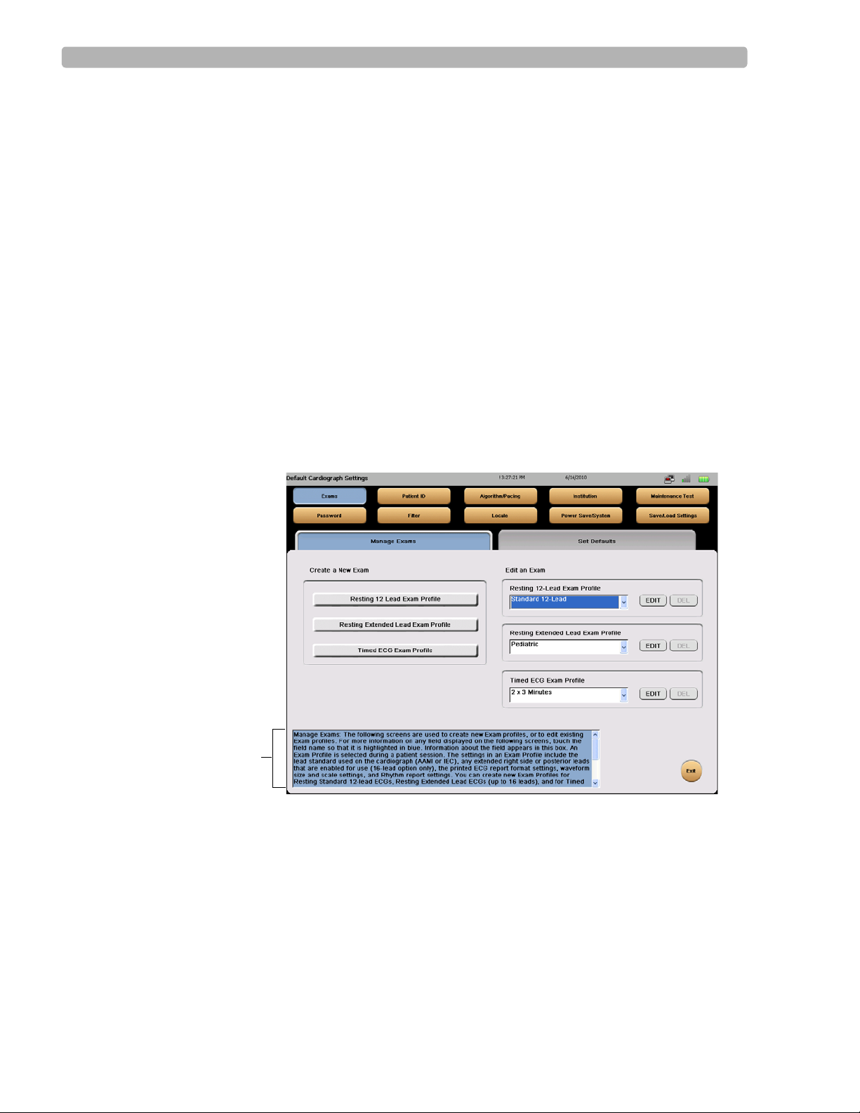
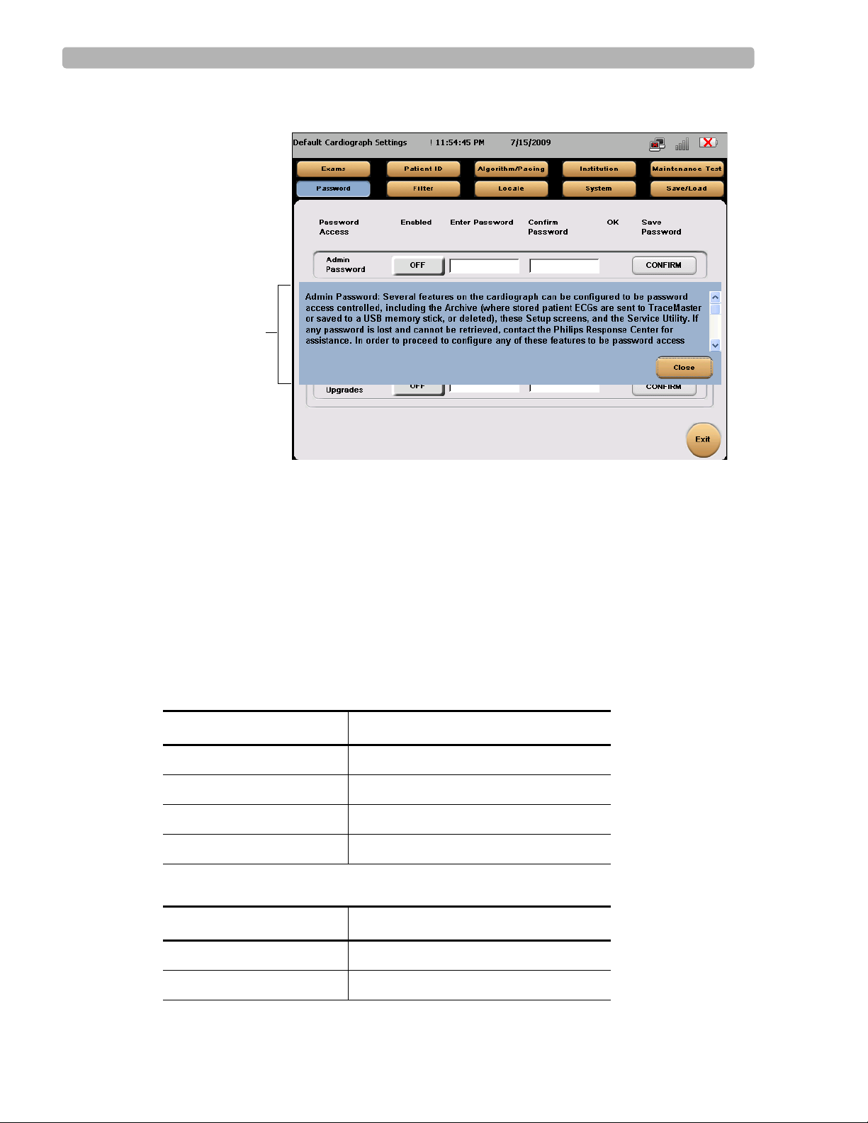
Each Setup screen within the cardiograph software application provides Help that describes
the currently selected option or field. Use the Help when configuring cardiograph settings, or
to learn more about a specific feature or item.
When a Setup screen is opened, Help displays in a blue Information box that appears on the
bottom of the screen. Touch a tab, or touch the name of any field or option displayed on the
screen to display Help for that specific item.
To view help for a tab or field:
Touch a tab or touch the name of the field or option so that it is highlighted in blue. Help
for the selected item displays in the blue Information box at the bottom of the screen (see
Figure 1-6 and Figure 1-7 on page 1-10).
Figure 1-6 PageWriter TC70 or TC50 Cardiograph Information Box on a Setup
screen
PageWriter TC Cardiograph Network Configuration Guide 1-9
Page 18
Overview of Workflow Options Contacting a Philips Response Center
A
Figure 1-7 PageWriter TC30 Cardiograph Information Box on a Setup screen
A Information Box
Contacting a Philips Response Center
The Philips Response Center can assist with product troubleshooting and provide technical
expertise to help with any issue with the PageWriter TC cardiographs or any of its accessories.
For more information on the Philips Response Center go to:
www.medical.philips.com/main/services/response_center
North America Response Centers
Country Telephone Number
Canada (800) 323 2280
Mexico 01 800 710 8128
Puerto Rico 1 787 754 6811
United States (800) 722 9377
South America Response Centers
Country Telephone Number
Argentina 54 11 4546 7698
1-10 PageWriter TC Cardiograph Network Configuration Guide
Brazil 0800 701 7789
Page 19

Overview of Workflow Options Contacting a Philips Response Center
South America Response Centers
Country Telephone Number
Chile 0800 22 3003
Columbia 01 8000 11 10 10
Peru 51 1 620 6440
Europe Response Centers
Country Telephone Number
United Kingdom 44 0870 532 9741
Fax: 44 01737 23 0550
Austria 43 1 60101 820
Belgium 32 2 525 7102 (French)
32 2 525 7103 (Flemish)
Czech Republic
31 40 2781619
MCR Response Center
(located in The
Netherlands)
Denmark 45 80 30 30 35
Finland 358 615 80 400
France 0 810 835 624
Germany 0180 5 47 5000
Greece
31 40 2781619
MCR Response Center
(located in The
Netherlands)
Hungary
31 40 2781619
MCR Response Center
(located in The
Netherlands)
Italy 0800 232100
Netherlands 31 40 27 211 27
Norway 47 800 84 080
PageWriter TC Cardiograph Network Configuration Guide 1-11
Page 20

Overview of Workflow Options Contacting a Philips Response Center
Europe Response Centers
Country Telephone Number
Poland
31 40 2781619
MCR Response Center
(located in The
Netherlands)
Rumania
31 40 2781619
MCR Response Center
(located in The
Netherlands)
Russia
31 40 2781619
MCR Response Center
(located in The
Netherlands)
Slovak Republic
31 40 2781619
MCR Response Center
(located in The
Netherlands)
Spain 34 90 230 4050
Sweden 46 200 81 00 10
Switzerland 0800 80 3000 (German)
0800 80 3001 (French)
Asia Response Centers
Country Telephone Number
Australia 1800 251 400
China 800 810 0038
Hong Kong 852 2876 7578
India 1600 112 444
Indonesia 62 21 7910040, ext 8610
Japan 81 (0)120 095 205
Korea 82 (0)2 3445 9010
Malaysia 1800 886 188
New Zealand 0800 251 400
Philippines 63 2 8162617 ext. 875
1-12 PageWriter TC Cardiograph Network Configuration Guide
Page 21

Overview of Workflow Options Contacting a Philips Response Center
Asia Response Centers
Country Telephone Number
Singapore 1800 Philips
Taiwan 0800 005 616
Thailand 66 (0)2 614 3569
Africa and Middle East
Country Telephone Number
All countries
MCR Response Center
(located in The Netherlands)
31 40 2781619
PageWriter TC Cardiograph Network Configuration Guide 1-13
Page 22

Overview of Workflow Options Contacting a Philips Response Center
1-14 PageWriter TC Cardiograph Network Configuration Guide
Page 23

Chapter 1Configuring Network Connectivity
About Network Settings
The PageWriter TC cardiographs communicate with various external servers using a wired or
wireless network connection, or a modem connection. In the network configuration settings
available on the cardiograph, all TCP/IP settings can be specified based on the needs of your
specific clinical environment.
Both automatic IP addressing via DHCP (Dynamic Host Configuration Protocol) and fixed IP
address settings are available. The network settings on the cardiograph support TCP/IP
protocol using a dynamic IP address or a static IP address, and support a DNS or WINS server.
Ethernet data transmission settings can be set to Auto Negotiation, where the system
automatically configures the correct settings for Ethernet speed and mode (half or full duplex),
or can be configured with fixed settings, if required.
2
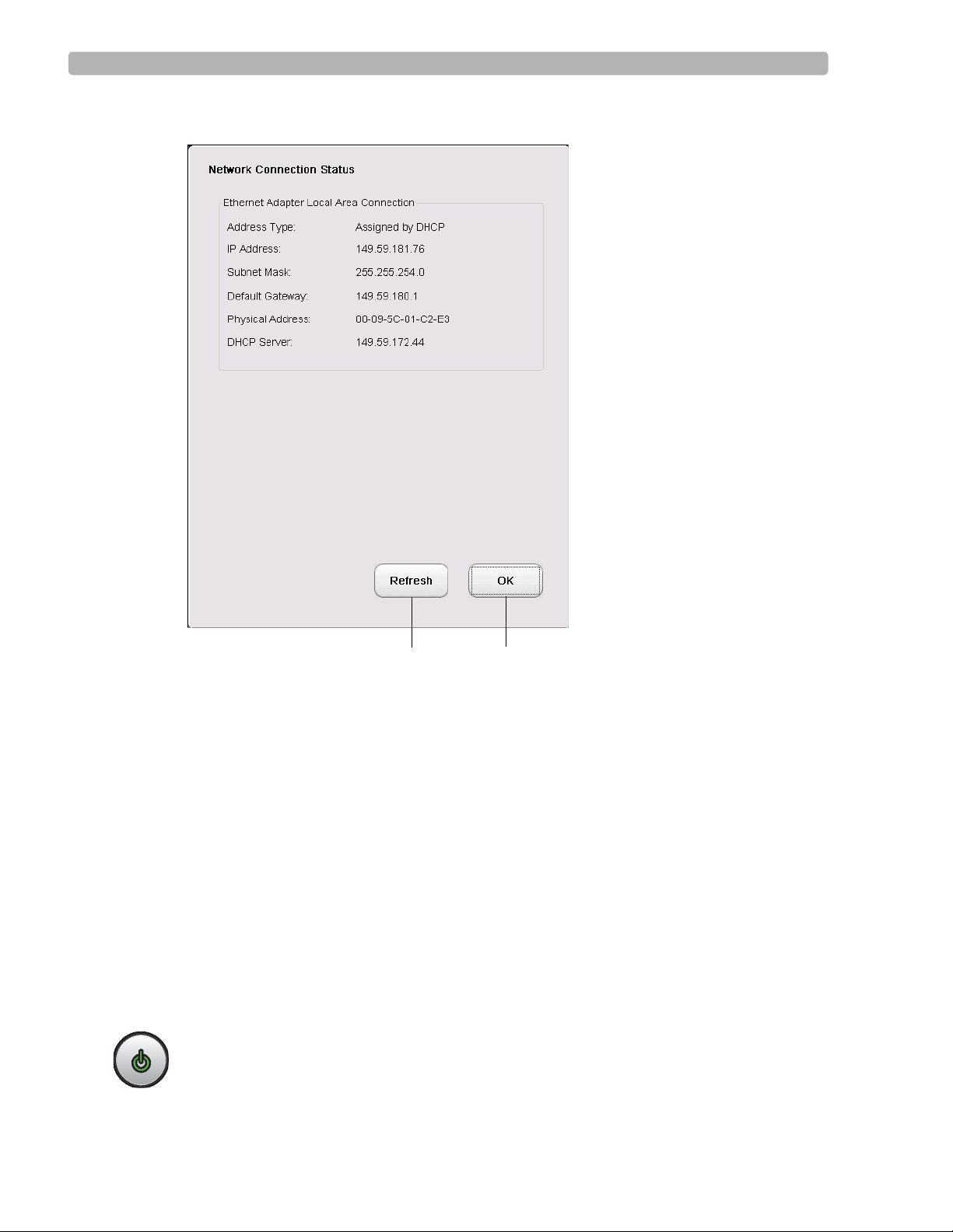
Network Connection Status Window
Tap the LAN icon or the wireless LAN icon on the Status Bar (top of screen) to view more
detailed information about a connection. The Network Connection Status window appears.
2-1
Page 24
Configuring Network Connectivity About Network Settings
Touch the Refresh button to
display the most current
network connection information
Touch the OK button to close
the window
Figure 2-1 The Network Connection Status window
About the Refresh Button
The Refresh button available on the Network Connection Status window (Figure 2-1 on
page 2-2) or on the Wire Network (LAN) or Wireless Network Setup screens, will (when
touched) obtain and display the most recently acquired IP address for the cardiograph. Please
note that this button does not provide a release and renew feature that is intended to acquire a
new IP address for the cardiograph. To obtain a new IP address for the cardiograph, you must
shut down and restart the cardiograph as described in the following procedure.
Obtaining a New IP Address for the Cardiograph
To obtain a new IP address for the cardiograph:
Ensure that any active patient data or ECG data has been saved.
1
NOTE When the cardiograph is shut down, any unsaved patient or ECG data is deleted.
2
Press and hold the On/Standby button on the cardiograph for two seconds. The
cardiograph shuts down.
3 Press the On/Standby button again to restart the cardiograph.
2-2 PageWriter TC Cardiograph Network Configuration Guide
Page 25

Configuring Network Connectivity About Network Settings
4 From the Main screen, touch the Setup button on the toolbar. The Setup main menu
appears.
5 On the menu, touch the Configure ECG Network Settings button.
6 The Wire Network tab is displayed, or to view the IP address set for a wireless
connection, touch the
Device Address field. The new IP address is displayed in the Device Address field.
Wireless Network tab. Touch the Refresh button next to the
Obtaining the IP Address Automatically (Using DHCP)
Touch the Obtain IP Address Automatically button (on the Wire Network or the Wireless
Network
unique MAC (Media Access Control) address of the cardiograph and provides a temporary
DHCP IP address. The IP address is obtained each time that the cardiograph is restarted, or is
returned to active use after being shut down.
tab) to retrieve an IP address dynamically from the network. The LAN records the
About Auto Negotiation
When obtaining the IP address from the local area network (LAN) dynamically using DHCP,
you can specify the Ethernet Adapter settings. The settings are set to Auto Negotiation, where
the system automatically configures the correct settings for Ethernet speed and mode (half or
full duplex).
NOTE If Auto-Negotiation fails, you may need to lock a specific switch or router port to a fixed setting (for
example, 100BaseT Full Duplex) to obtain a connection. For details, see “Configuring Manual Ethernet
Settings” on page 2-8.
Specifying IP Address (Fixed IP)
Touch the Specify IP Address button to define a fixed IP address for the cardiograph. Using a
fixed IP address allows the cardiograph to be recognized from multiple locations while
connected to the LAN, and does not require that the IP be reset in order to be recognized.
Using fixed IP addresses also avoids the problem of having multiple IP addresses assigned to a
single cardiograph.
Checking the Cardiograph IP Address
The Device Address field on the Wire Network and Wireless Network tabs displays the
current IP address for the cardiograph for each connection type.
If using a dynamic IP address using DHCP (by selecting the
Automatically
cardiograph is fully restarted, or is returned to active use after being shut down.
option), the IP address is automatically refreshed each time that the
Obtain IP Address
PageWriter TC Cardiograph Network Configuration Guide 2-3
Page 26

Configuring Network Connectivity Configuring Cardiograph Network Settings
To view the IP address for the cardiograph:
1
On the Main screen, touch Setup on the toolbar. The Setup ma in menu appears.
2 On the menu, touch the Configure ECG Network Settings button. The Wire Network
tab is displayed.
The IP address for the Ethernet (wired) connection is displayed in the
field. Touch the
3 To view the IP address set for a wireless connection, touch the Wireless Network tab.
The IP address for the wireless connection is displayed in the
Touch the
Refresh button to view the most current IP address for the connection.
Device Address field.
Refresh button to view the most current IP address for the connection.
Device Address
For information on manually resetting the IP address, see “Obtaining a New IP Address for the
Cardiograph” on page 2-2.
Configuring Multiple Cardiographs
When configuring multiple cardiographs with the same networking, TraceMaster, or
OrderVue settings, you can save all settings to a USB memory stick as a Network Settings file,
and then upload the settings to additional PageWriter TC cardiographs.
NOTES Wireless LAN card settings specified in the Summit WLAN Adapter are saved with the Network
Settings file.
You can load the same Network Settings file on all models of the PageWriter TC cardiograph.
Configuring Cardiograph Network Settings
If assistance is required with any of the settings described in this section, please consult your
network administrator.
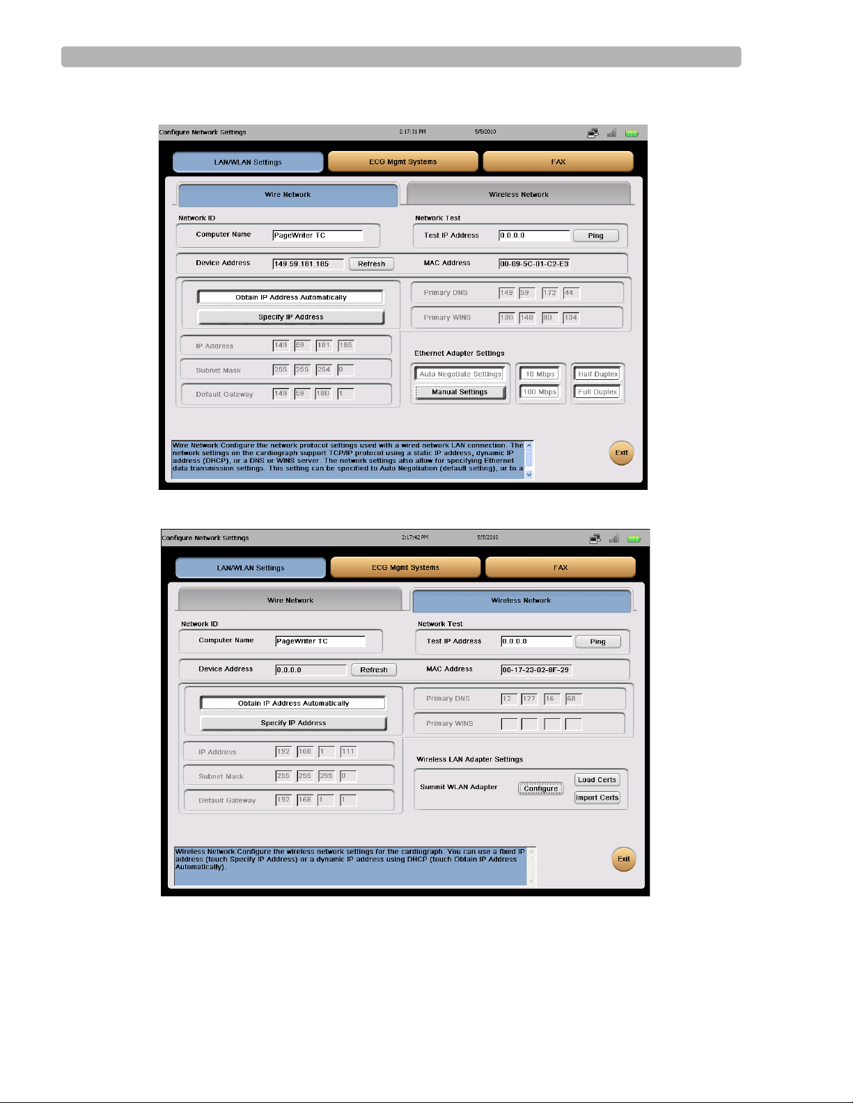
The Network settings are contained on two tabs:
specify connection settings using the appropriate tab. The selected tab is highlighted in blue.
TIP The blue information box at the bottom of each screen provides help information for all settings.
Touch the name of a setting to display help for that item. The selected item is highlighted in blue.
Wire Network and Wireless Network. You
2-4 PageWriter TC Cardiograph Network Configuration Guide
Page 27
Configuring Network Connectivity Configuring Cardiograph Network Settings
Figure 2-2 Wire Network tab
Figure 2-3 Wireless Network tab
For details on configuring network settings, see:
“Configuring Wired LAN (Ethernet) Settings” on page 2-6.
“Configuring Wireless LAN Settings” on page 2-12.
PageWriter TC Cardiograph Network Configuration Guide 2-5
Page 28
Configuring Network Connectivity Configuring Cardiograph Network Settings
Configuring Wired LAN (Ethernet) Settings
On the network configuration screen, you can define how the IP address is set (dynamic or
fixed), specify the subnet mask, default gateway, and primary DNS, and/or primary WINS.
To configure Wired LAN (Ethernet) settings:
1
On the toolbar, touch Setup. The Configuration Setup and Service Utilities menu appears.
2 On the menu, touch Configure ECG Network Settings. The Wire Network tab appe ars.
3 Touch the appropriate IP Address button:
– To use a dynamic IP address that is retrieved automatically each time the cardiograph
is reset, touch
Proceed to step
– If using a static IP Address, please proceed to step
Depending on which selection you make, different options are enabled on the tab.
4 If using a dynamic IP address, specify the following settings:
Setting Description
Obtain IP Address Automatically. This settings is enabled by default.
4.
5.
Computer Name
IP Address
Touch the text-entry field and type a unique name to
identify the specific cardiograph on the network (up to
sixteen letters or numbers).
NOTES
The Computer Name field cannot be left blank and cannot
contain any special characters or spaces. This field can only
contain the letters A-Z or the numerical digits 0-9.
If this field is left blank, PageWriter TC will appear in
this field by default.
The LAN automatically provides a dynamic IP address
to the cardiograph. The LAN records the unique MAC
(Media Access Control) address of the cardiograph and
provides a temporary DHCP IP address.
T o manually retrieve a new IP address from the network,
shut down the cardiograph (press and hold the On/
Standby button) ( ) and then press the On/Standby
button ( ) again to restart the cardiograph. This resets
the temporary DHCP IP address.
The Ethernet Adapter settings are always set to
Proceed to step
2-6 PageWriter TC Cardiograph Network Configuration Guide
6.
Auto Negotiation (page 2-3).
Page 29

Configuring Network Connectivity Configuring Cardiograph Network Settings
5 If specifying a fixed IP address, specify the following settings:
Setting Description
Computer Name
Touch the text-entry field and type a unique name to
identify the specific cardiograph on the network (up to
sixteen letters or numbers). This field is required, and
cannot be left blank.
NOTES
The Computer Name field cannot be left blank and cannot
contain any special characters or spaces. This field can only
contain the letters A-Z or the numerical digits 0-9.
If this field is left blank, PageWriter TC will appear in
this field by default.
PageWriter TC Cardiograph Network Configuration Guide 2-7
Page 30

Configuring Network Connectivity Configuring Cardiograph Network Settings
Setting Description
IP Address
Touch the first text entry field and, using the Tab key to
move between fields, type the IP address for this
cardiograph. No separating period (.) is required.
Subnet Mask
Touch the first text entry field and, using the Tab key to
move between fields, type the (optional) subnet mask
address. No separating period (.) is required.
Default Gateway
Touch the first text entry field and, using the Tab key to
move between fields, type the (optional) default
gateway. No separating period (.) is required.
Primary DNS
Touch the first text entry field and, using the Tab key to
move between fields, type the (optional) primary DNS
address. No separating period (.) is required.
Primary WINS
Touch the first text entry field and, using the Tab key to
move between fields, type the (optional) primary WINS
address. No separating period (.) is required.
6 Touch Exit, then touch Yes when prompted to save your settings.
After saving your changes, the IP address is saved in the registry. Other configuration settings
are saved in the configuration file.
Configuring Manual Ethernet Settings
By default, the cardiograph is configured for auto-negotiation. If auto-negotiation fails, you
may need to lock a specific switch or router port to a fixed setting (for example, 100BaseT Full
Duplex) to obtain a connection.
You specify the settings in the Ethernet Adapter Settings section of the
Wireless Network tabs (depending on your connection type).
To configure manual Ethernet settings:
On the Wire Network or Wireless Network tab, touch Manual Settings.
1
The buttons for each of the settings are enabled.
2 Touch the button(s) to select the appropriate settings. Options are 10 or 100 Mbps, Half or
Full Duplex.
NOTES Half Duplex means that data can be transmitted in both directions on a signal carrier, but not at
the same time. Full Duplex means that data can be transmitted in both directions on a signal
carrier, at the same time.
3
Save the settings by touching Exit.
Wire Network or
2-8 PageWriter TC Cardiograph Network Configuration Guide
Page 31

Configuring Network Connectivity Configuring Cardiograph Network Settings
4 When prompted to save your changes, touch Yes.
The cardiograph saves the settings to the registry and returns you to the Setup menu. You
must now restart the cardiograph.
5 Press and hold the On/St andby button for two seconds. The cardiogr aph shuts down. Press
the On/Standby button again to restart the cardiograph. The new settings are now applied.
About Wireless LAN Settings
The PageWriter TC cardiographs offer wireless connectivity through cardiograph wireless
LAN options D21 and D22. Both of these wireless options include the Summit Data
Communications Compact Flash Card wireless adapters with Integrated Antenna (also
referred to as a radio card). These adapters offer an integrated diversity antenna with
enhanced transmit power and receiver sensitivity, and with superior delay spread and roaming
capabilities, delivering dependable connectivity in almost all demanding clinical
environments, including those with limited access point availability, and those with numerous
and competing wireless devices.
The D21 adapter is compatible with both the 802.11b and g wireless standards, and operates in
the 2.4 GHz section of the radio frequency spectrum, providing a data transmission rate of 54
megabits per second (Mbps). The D22 adapter is compatible with the 802.11a, b, and g
standards, and operates dually in either the 2.5 GHz or 5 GHz section of the radio frequency
spectrum. Operating in the 5 GHz range provides optimal connectivity in high use,
competitive wireless environments. The PageWriter TC cardiograph software includes the
Summit Client Utility (SCU), which allows you to configure all radio operation and security
settings. The utility also enables you to view operating status and to troubleshoot adapter
issues.
Other Resources and Information
For additional information about the Summit adapter, see the product documentation available
at the Summit web site,
http://www.summitdatacom.com.
Supported Security Options
Authentication is supported through an integrated 802.1x supplicant supporting authentication
using pre-shared keys, as well as a broad range of Extensible Authentication Protocol
types, including EAP-TLS, PEAP-GTC, LEAP, PEAP-MSCHAPv2, and EAP-FAST.
NOTE The wireless LAN adapter does not support the EAP-TTLS authentication protocol.
Data privacy is ensured via encryption and decryption using AES (WPA2), TKIP (WPA), or
WEP. A comparison of popular EAP types used with 802.1X authentication and the certificate
requirements for the different authentication methods is included in Table 2-1.
You configure all wireless LAN security and connection options on the network configuration
screens accessed through the
Setup button on the main toolbar.
(EAP)
PageWriter TC Cardiograph Network Configuration Guide 2-9
Page 32

Configuring Network Connectivity Configuring Cardiograph Network Settings
NOTE Some authentication methods may require that a valid authentication certificate be loaded and enabled
on the cardiograph. For details on loading a certificate, see “Loading Authentication Certificates” on
page 2-16.
Table 2-1 Popular EAP types
Type Credential(s) Database(s) Pros and Cons
LEAP Microsoft
password
PEAP with EAPMSCHAP
PEAP with EAPGTC
Microsoft
password
Password
One-time
password
Token
EAP-FAST
Microsoft
Active
Directory (AD)
AD
AD, NDS,
LDAP, OTP
database
AD, others
password
Others
EAP-TLS Client certificate Certificate
authority (CA)
No certificates
Strong password required
Native support in Windows, CE
CA certificate on every client device
Broad range of credentials
CA certificate on every client device
No certificates
Complex provisioning process
Requires PAC file to be statically or
dynamically loaded on the client
device
Very strong authentication
Native support in Windows, CE
CA, user certificates on every client
device
2-10 PageWriter TC Cardiograph Network Configuration Guide
Page 33

Configuring Network Connectivity Configuring Cardiograph Network Settings
Table 2-2 describes the authentication options in the Summit Client Utility (SCU). The SCU
offers the following security setting options.
Table 2-2 Summit Client Utility Security Settings
Setting Description See ...
Encryption
This setting specifies the type of encryption that
the wireless adapter will use, and how the
encryption key will be created.
None: No encryption
Manual WEP: Wireless Equivalency Privacy
(WEP) with up to four static keys that can be
40-bit, 128-bit in ASCII, or 128-bit in hex.
Touch the
WEP keys/PSK button to enter the
keys.
Auto WEP: WEP with the key generated
during EAP authentication
WPA-PSK: TKIP with PSK, either ASCII
passphrase PSK or hex PSK. Touch the
keys/PSK
WPA-TKIP: TKIP with key generated during
button to enter the keys.
WEP
EAP authentication
WPA2-PSK: AES with PSK, either ASCII
passphrase PSK or hex PSK. Touch the
keys/PSK
button to enter the keys.
WEP
For details about setting these
options, see “Configuring Wireless
Adapter Settings” on page 2-19.
For additional information, consult
your network administrator and the
Summit documentation available at
http://www.summitdatacom.com.
WPA2-AES: AES with key generated during
EAP authentication
CCKM-TKIP: TKIP with key generated during
EAP authentication and with Cisco key
management protocol for fast
reauthentication
CKIP Manual: WEP with up to four static keys,
plus Cisco TKIP and/or Cisco MIC if
configured on AP. Touch the
WEP keys/PSK
button to enter the keys.
CKIP Auto: WEP with key generated during
EAP authentication, plus Cisco TKIP and/or
Cisco MIC if configured on AP.
PageWriter TC Cardiograph Network Configuration Guide 2-11
Page 34

Configuring Network Connectivity Configuring Cardiograph Network Settings
Table 2-2 Summit Client Utility Security Settings
Setting Description See ...
EAP Type
This setting is used with EAP authentication. For
more specifics on the available EAP types,
including certificate requirements, see Table 2-1
on page 2-10.
The available settings include:
None
LEAP
EAP-FAST
PEAP-MSCHAP
PEAP-GTC
EAP-TLS
(continued)
For details about setting these
options, see “Configuring Wireless
Adapter Settings” on page 2-19.
For additional information, consult
your network administrator and the
Summit documentation available at
http://www.summitdatacom.com.
Configuring Wireless LAN Settings
Configuring your wireless connection involves the following steps:
Configuration Step See ...
Install the wireless adapter and protective cover.
1
If your cardiograph already has the adapter
installed, proceed to step
2 Load an authentication certificate and private keys,
2.
if necessary.
“Installing the Wireless LAN
Card and Cover” on page 2-13
“Loading Authentication
Certificates” on page 2-16
If the encryption method you will use does not
require authentication certificate and private keys,
proceed to step
3 Configure one or more wireless profiles using the
Summit Client utility, accessed from the Wireless
3.
“Configuring Wireless Adapter
Settings” on page 2-19
Network configuration screen.
4 Select a profile to use, and restart the cardiograph. “Selecting the Active Profile” on
page 2-25
2-12 PageWriter TC Cardiograph Network Configuration Guide
Page 35

Configuring Network Connectivity Configuring Cardiograph Network Settings
Before You Begin
Before you start the configuration process, ensure you have the following available:
If you purchased the PageWriter TC Cardiograph Wireless LAN Upgrade Kit, you will
install the wireless adapter and its protective cover before configuring the adapter. For
details, see “Installing the Wireless LAN Card and Cover” on page 2-13.
If the cardiograph was shipped to you with the adapter installed (see Figure 2-4 on
page 2-13), you can proceed to loading certificates (if needed) and configuring the
adapter.
Authentication certificate, loaded onto a USB memory stick, if needed for the desired
encryption method
Certificate requirements for each encryption method are described in Table 2-1 on page 2-
10. Contact your network administrator to generate a certificate file for the authentication
method the cardiograph will use, if required. For details, see “Loading Authentication
Certificates” on page 2-16.
Installing the Wireless LAN Card and Cover
If you purchased the PageWriter TC Cardiograph Wireless LAN Upgrade Kit, you will install
the wireless adapter and its protective cover before proceeding with configuring the adapter.
For details, see “Installing the Wireless LAN Card and Cover” on page 2-13.
If the cardiograph was shipped to you with the wireless LAN adapter installed, you can skip
this installation procedure. The wireless LAN adapter, when installed in the cardiograph, is
housed inside of a plastic cover that protects the adapter from outside conditions, and also
prevents the adapter from being easily removed from the cardiograph. You can proceed
loading certificates (if needed) and configuring the adapter.
Figure 2-4 Summit Wireless LAN adapter with protective cover
CAUTION Only use Summit wireless LAN adapters with the PageWriter TC cardiograph that have been
purchased from Philips Medical Systems. The use of non-approved wireless LAN cards with the
PageWriter TC cardiograph is not tested or supported, and Philips Medical Systems does not
guarantee cardiograph operation or wireless LAN connectivity.
PageWriter TC Cardiograph Network Configuration Guide 2-13
Page 36

Configuring Network Connectivity Configuring Cardiograph Network Settings
The PageWriter TC Cardiograph Wireless LAN Upgrade Kit includes the Summit adapter, a
plastic protective cover, and two screws that are used to secure the cover to the cardiograph.
To install the wireless adapter and the protective cover:
1
Remove the flat plastic cover that is secured over the PC card slot on the rear panel of the
cardiograph. Once the plastic cover is removed, the PC card slot is visible.
2 Insert the Summit WLAN adapter into the PC card slot as shown. Ensure that the adapter
is fully inserted into the slot.
2-14 PageWriter TC Cardiograph Network Configuration Guide
Page 37

Configuring Network Connectivity Configuring Cardiograph Network Settings
3 Place the protective cover over the adapter and secure it with the two screws as shown.
You are now ready to configure the adapter for use.
About Authentication Certificates and Private Keys
The PageWriter TC cardiograph supports authentication certificates. For general certificates,
use the
private keys) from a USB memory stick into the Summit Client Utility’s certificate directory.
For user certificates (for example, EAP-TLS), use the
Microsoft Certificate Utility, which allows you to import a user certificate and private key
(located in the Summit Client Utility’s certificate directory) into the Microsoft System store.
Load Certs button to load and enable certificates (for example, 509 certificates and
Import Certs button to launch the
Figure 2-5 Wireless Network Setup Screen with Load Certs and Import Certs options
PageWriter TC Cardiograph Network Configuration Guide 2-15
Page 38

Configuring Network Connectivity Configuring Cardiograph Network Settings
If the encryption method you are using requires a certificate or an optional private key, have
the network administrator generate the certificate/private key as required, and load these files
onto a USB memory stick.
CAUTIONS Do not insert a USB memory stick into the cardiograph, or remove a USB memory from the
cardiograph when the cardiograph is acquiring ECG data from a patient.
The PageWriter TC cardiograph only supports the USB memory stick that is available for purchase
as an optional accessory from Philips Medical Systems. Philips does not guarantee that other USB
memory sticks are compatible with the PageWriter TC cardiograph.
Follow the steps described below to load authentication certificates and private keys, as
required.
Configuration Step See ...
1 Load an authentication certificate “Loading Authentication
Certificates” on page 2-16
2 Import user certificates and private keys “Importing User Certificates and
Private Key” on page 2-18
Loading Authentication Certificates
To load an authentication certificate:
Ensure the certificate is on a USB memory stick. Contact your network administrator for
1
the certificate.
2 Insert the USB memory stick into the USB connector located on the front right side of the
cardiograph.
3 On the Main screen, touch Setup on the toolbar.
The Configuration Setup and Service Utilities menu appears.
2-16 PageWriter TC Cardiograph Network Configuration Guide
Page 39

Configuring Network Connectivity Configuring Cardiograph Network Settings
4 Touch Configure ECG Network Settings.
The Configure Network Settings screens appear, and by default, the
LAN/WLAN Settings
tab (top of screen) is selected (highlighted in blue).
5 Touch the Wireless Network tab.
The wireless settings appear. The Wireless LAN Adapter Settings section provides access
to the Summit Client Utility (SCU) and to the Certificate loading utility.
6 Touch Load Certs. The Load Personal Certificate window appears. Touch Browse. This
shows the contents of the USB drive.
7 Locate and select the desired certificate, then touch OK to accept the entry and load the
certificate.
PageWriter TC Cardiograph Network Configuration Guide 2-17
Page 40

Configuring Network Connectivity Configuring Cardiograph Network Settings
8 If a private key is required, repeat step 6, but load the private key file.
9 Touch OK to close the window. The certificate is now loaded.
10 Verify the certificate is loaded from within the Summit Configuration Utility.
11 If you are using a user certificate that also has a private key, go to “Importing User
Certificates and Private Key” on page 2-18.
Importing User Certificates and Private Key
To import user certificates and private key:
1
Follow the instructions in “Loading Authentication Certificates” on page 2-16 to open the
Wireless Network Setup screen.
2 On the Wireless Network Setup screen, touch the Import Certs button.
3 Touch the dropdown list under the selected Stores tab, and select My Certificates. The list
of certificates that were previously loaded following the procedure “Loading
Authentication Certificates” on page 2-16 appear at the right.
4 Select the desired certificate file, then touch Import. The Import Certificate or Key
window appears, with the
From a File radio button selected.
5 Touch OK (top right of window). The Select a Certificate File browser opens.
6 Navigate to the Certificates folder by touching Storage Card, and then press the Enter
key (on keyboard).
7 On the following window, touch Philips, and then press the Enter key (on keyboard).
8 Ensure the Type dropdown (bottom of window) displays Certificates, and then touch the
certificate file to import. When done, touch
OK (top of the window). The certificate is
loaded onto the cardiograph.
9 To import the associated private key, repeat steps 3 through 8. In step 4, select the private
key file, then touch
10 In the Type dropdown (bottom of window), select Private Keys.
11 Touch the private key file to import, and then touch OK (top of window).
12 You are prompted for the password. Type the password associated with the key, and then
OK (top of the window). The private key is now imported.
touch
13 To confirm that the key was imported, touch the View button on the Certificates dialog
Import.
box. The Properties dialog box appears.
14 In the Field list, touch Private Key. If the key was properly imported, the Detail pane will
display
Present.
15 You now need to enable the certificate in the Summit Adapter Utility. Launch the Summit
Adapter Utility.
16 Touch Admin Login and log into the utility, see “Configuring Wireless Adapter Settings”
on page 2-19 for more information on using the utility.
2-18 PageWriter TC Cardiograph Network Configuration Guide
Page 41

Configuring Network Connectivity Configuring Cardiograph Network Settings
17 T ouch the Profile tab, then touch the Credentials button. You are prompted to provide the
user credentials.
18 Type the name of the certificate to use, and touch OK. The utility validates the certificate.
19 T ouch the Main tab of the utility, and you will see that the connection becomes secured by
the certificate. You can now exit the utility.
Configuring Wireless Adapter Settings
All wireless LAN settings are contained in a Profile that is created within the Summit Client
Utility (SCU). Once a profile is created, you can apply it to the cardiograph by selecting it as
the
Active Profile in the SCU.
You only need to configure the following settings for immediate use, which are described in
the next procedure:
SSID (service set identifier) of the wireless network you are using
Encryption method to use
If using a certificate for the selected encryption method, the user name and password
associated with the certificate
You can fine tune additional profile settings. The following table provides a high-level
overview of the settings you can configure. For more detailed information about fine-tuning
any of the settings in the SCU, refer to the Summit product documentation available at
www.summitdatacom.com.
Table 2-3 Summit Client Utility Profile Settings Overview
Setting Description Philips Recommended Default Setting
SSID
(Service Set
Identifier)
Client Name Defining a name (up to 16
Defines the accessible
access point(s). Can
contain up to 32
characters, and is case
sensitive.
characters) for the specific
Consult your network administrator for
more information on this setting.
NOTE If you leave the SSID field blank, the
cardiograph can associate with any access point
on the network that is configured to accept
broadcast SSIDs.
Consult your network administrator for
more information on this setting.
cardiograph allows an
administrator to determine
what devices are
connected to the network.
PageWriter TC Cardiograph Network Configuration Guide 2-19
Page 42

Configuring Network Connectivity Configuring Cardiograph Network Settings
Table 2-3 Summit Client Utility Profile Settings Overview
(continued)
Setting Description Philips Recommended Default Setting
Power Save Defines the power
consumption level for the
Fast PSP (Power Save Mode)
NOTES
wireless adapter.
CAM (Constantly
Awake Mode)
Maximum (Maximum
power savings)
Fast PSP (Fast power
save mode)
Tx Power Defines the power level at
Fast PSP is a power saving mode that
automatically adjusts battery consumption
based upon the amount of network traffic.
For example, during periods of low network
activity, less power is consumed.
CAM is not recommended for use due to
high power consumption.
The Maximum setting is not recommended
due to the low level of data throughput.
Max
which the wireless adapter
transmits to the access
point.
Max: Automatically
uses the maximum
allowable transmit
NOTE The Transmit Power setting can be
overridden by a Cisco AP if the CCX Support
global setting is set to Full, and AP defines
maximum transmit power for client as lower
value.
setting as defined by
the local regulatory
domain
Manual setting to any
of the following (all
in milliwats): 50, 30,
20, 10, 5, 1 (mW)
Bit Rate Specifies the bit rate used
by radio when interacting
with an AP.
Auto: Bit rate is
automatically
negotiated with the
AP
Manual setting at any
of the following (all
in megabits per
second): 1, 2, 5.5, 6,
9, 11, 12, 18, 24, 36,
48, 54 (Mbps)
2-20 PageWriter TC Cardiograph Network Configuration Guide
Auto
NOTE If you specify a manual bit rate setting,
the radio will connect to an AP only if that AP
has the specified SSID configured with the
selected bit rate as the only required rate.
Page 43

Configuring Network Connectivity Configuring Cardiograph Network Settings
Table 2-3 Summit Client Utility Profile Settings Overview
(continued)
Setting Description Philips Recommended Default Setting
Radio Mode
D21 Wireless
LAN Option
only
Defines the frequencies
and data rates used when
interacting with an access
point (AP).
BG rates full: Includes
all 802.11b and
802.11g rates
BG rates subset:
Includes a subset of
values including 1, 2,
5.5, 6, 11, 24, 36, and
BG rates full
NOTES
The BG rates subset setting should only be
used with Cisco APs running IOS in
autonomous mode (without controllers).
For Cisco APs that are tied to controllers
and for non-Cisco APs, use the BG rates full
setting.
The PageWriter TC cardiograph does not
support the Ad Hoc setting, or any type of
peer-to-peer communication.
54 Mbps (see note)
802.11b
1, 2, 5.5, and 1 1 Mbps
802.11 g
6, 9, 12, 18, 24, 36,
48, and 54 Mbps
Ad Hoc (not
supported, see note)
Radio Mode
D22 Wireless
LAN Option
only
A rates only: 6, 9, 12,
18, 24, 36, 48, and 54
Mbps
ABG rates full: all
802.11a rates and all
802.11b and 802. 11g
rates, with 802.11a
rates preferred
BGA rates full: all
802.11b and 802. 11g
rates and all 802.11a
rates, with 802.11b
and 802.11g rates
preferred
Ad Hoc (not
supported, see note)
ABG rates full
NOTE
The PageWriter TC cardiograph does not
support the Ad Hoc setting, or any type of
peer-to-peer communication.
PageWriter TC Cardiograph Network Configuration Guide 2-21
Page 44

Configuring Network Connectivity Configuring Cardiograph Network Settings
Table 2-3 Summit Client Utility Profile Settings Overview (continued)
Setting Description Philips Recommended Default Setting
Authentication
Type
Defines how the wireless
adapter attempts to
authenticate to an access
point.
Open
Shared-key
LEAP (Network-
EAP)
Encryption See Table 2-2 on page 2-11Consult your network administrator for
EAP Type See Table 2-2 on page 2-11Consult your network administrator for
NOTES Before proceeding with this section:
Ensure that the wireless adapter is properly installed in the cardiograph.
Load any required authentication certificates for wireless access. Table 2-1 on page 2-10 describes
the encryption methods and whether certificates are required. For installation details, see “Loading
Authentication Certificates” on page 2-16.
Consult your network administrator for
more information on this setting.
more information on this setting.
more information on this setting.
To configure wireless adapter settings:
1
On the Main screen, touch Setup on the toolbar.
The Configuration Setup and Service Utilities menu appears.
2 On the menu, touch Configure ECG Network Settings.
The Configure Network Settings screens appear, and by default, the
LAN/WLAN Settings
tab is selected (highlighted in blue).
3 Touch the Wireless Network tab.
The wireless settings appear. The Wireless LAN Adapter Settings section provides access
to the Summit Client Utility (SCU) and to the Certificate loading utility. See figure on
page 2-17.
4 In the Summit WLAN Adapter section, touch Configure.
The Summit Client Utility (SCU) appears. To configure adapter settings, you must log in
and enter the Administrator view.
2-22 PageWriter TC Cardiograph Network Configuration Guide
Page 45

Configuring Network Connectivity Configuring Cardiograph Network Settings
Tabs
5 Touch Admin Login.
The Admin Password Entry window appears.
6 Type the default password SUMMIT (all caps).
NOTE To change the password, touch the Global tab, and then select Admin Password from the
Properties list.
Touch the Profile tab (top of window).
7
The Profile tab shows all of the settings on this tab can be saved as an individual
profile defines all of the wireless settings applied to the cardiograph. The currently
selected profile appears in the
Profile dropdown list (top of window).
The first time that the SCU is run, the selected profile is
You can now either create a new profile, or simply edit the settings associated with the
Default profile.
NOTE You can define up to 20 individual profiles.
Do any of the following:
8
– To create a new profile, touch
New; you are prompted to name the profile. When
finished, you can configure settings for the profile.
– To rename the Default profile, touch
profile. When finished, you can configure settings for the profile.
The mandatory settings to configure are the SSID, Encryption method, and certificate
access, if used.
profile. A
Default.
Rename; you are prompted to rename the
The
Radio list contains all of the available settings. For a high-level overview of each
option, see Table 2-3, “Summit Client Utility Profile Settings Overview,” on page 2-19.
Touch the scroll bar to move through the options in the list, and touch an option to select
it.
PageWriter TC Cardiograph Network Configuration Guide 2-23
Page 46

Configuring Network Connectivity Configuring Cardiograph Network Settings
9 Touch SSID in the Radio list to specify the SSID.
The field to the right of the dropdown list is blank. Type the desired entry. The SSID can
be up to 32 characters in length, and is case sensitive.
NOTE If you leave the SSID field blank, the cardiograph can associate with any access point on the
network that is configured to accept broadcast SSIDs.
To set the encryption method, do the following:
10
a Touch the Encryption dropdown arrow, and select the desired method.
The following figure shows the
EAP-FAST TKIP option selected. This method requires a
certificate. Other methods may require that you enter a passphrase or key; in that case,
the
WEP keys/PSKs button will be active (for an example, go to step d).
b If the method requires a certificate, touch Credentials. If it does not, proceed to step
d.
The Credentials dialog box appears.
c In the User field and Password fields, type the user name and password associated with
the certificate, then touch
d If the encryption method does not require a certificate but requires a passphrase or
WEP key, touch
Wep keys/PSKs.
OK.
The PSK Entry dialog box appears.
2-24 PageWriter TC Cardiograph Network Configuration Guide
Page 47

Configuring Network Connectivity Configuring Cardiograph Network Settings
e Type the entry, then touch OK.
11 When finished, touch Commit to save changes to the profile.
You can now select the profile to use, as described next. You will select a profile, and then
reboot the cardiograph to apply the settings.
Selecting the Active Profile
The active profile defines the operating parameters for the wireless adapter.
To select the active profile:
1
Do one of the following:
– If you just finished configurin g a profile as described in the previous proced ure, touch
Main tab.
the
– If you are activating a different profile, access the SCU as described in steps
4 on page 2-22, then touch the Main tab.
1 through
2 Touch the Active Profile dropdown arrow to display the list of available profiles.
3 Touch a profile to select it.
The list closes with the selected profile displayed. The profile settings are applied.
4 If configuration is complete, and all certificates have been loaded, touch OK at the top
right hand corner of the SCU window to close the utility.
5 To exit the setup screens, touch Exit at the bottom right of the screen. You may be
prompted to save changes.
6 The cardiograph must restart in order for the new wireless settings to be applied. Press and
hold down the On/Standby button ( ) (front panel of cardiograph) for five seconds to
shut down the cardiograph.
7 Press the On/Standby button again to restart the cardiograph.
The new wireless settings are applied.
PageWriter TC Cardiograph Network Configuration Guide 2-25
Page 48

Configuring Network Connectivity Testing the Network or Modem Connection
Wireless LAN
Connectivity Indicator
Wireless LAN Connectivity Indicator
The status of the wireless LAN connection displays on the Status Bar located at the top of any
cardiograph screen.
Figure 2-6 Wireless LAN Status Indicator on Status Bar
Table 2-4 Wireless LAN Connectivity Indicator
Label Description
Wireless LAN
Connectivity
Wireless LAN connectivity:
Indicates the signal strength of the wireless LAN
connection.
Green bars indicate that the wireless adapter is associated to
an access point. The higher the number of green bars, the
better the connection.
Gray bars indicate that the wireless adapter is unable to
associate to an access point.
Testing the Network or Modem Connection
Use the Ping Test available in the Maintenance Test menu in Setup to verify that the
configured wired or wireless network connection can successfully communicate over a
network connection to an entered IP address.
To perform the Ping Test:
Ensure that the LAN cable is securely attached to the LAN connector ( ) on the rear
1
of the cardiograph, or that the wireless LAN adapter is associated to an access point and
that green bars appear on the Status bar (top of screen), indicating a live wireless
connection.
2 Touch the Setup button on the toolbar. The Configuration Setup and Service Utilities
menu appears.
3 On the menu, touch Configure Cardiograph Default Settings. On the Default
Cardiograph Settings screen, touch the
screen).
4 On the Maintenance Test screen, touch the Ping Test button. The Ping Test window
appears.
5 Enter the IP address to ping. Touch the Ping button.
6 The Ping Test results window appears and reports the test results.
2-26 PageWriter TC Cardiograph Network Configuration Guide
Maintenance Test button (upper right side of
Page 49

3
Chapter 1Configuring TraceMaster ECG
Management System Settings
The PageWriter TC cardiographs can communicate over an Ethernet LAN, wireless LAN, or
modem with the Philips TraceMaster ECG Management System for an integrated order and
ECG management workflow solution. Enabling cardiograph connectivity with a TraceMaster
server allows for the direct downloading of pending patient orders to the cardiograph, and for
the subsequent uploading of completed orders and associated ECGs to TraceMaster for
reconciliation, review, and processing. Also, you can enable the Last ECG and interactive
query features on the cardiograph so that you can download ECGs directly from a
TraceMaster server to the cardiograph for on-screen review, printing, and previous ECG
comparison purposes directly at the cardiograph.
For more information on any optional cardiograph features described in this chapter (LAN,
wireless LAN, modem, orders, ADT support), consult your Philips sales representative, or
your local dealer or distributor.
Configuring connectivity between a cardiograph and the TraceMaster ECG Management
System with the OrderVue order handling option involves multiple steps, as described in the
following table.
Table 3-1 Configuring TraceMaster Connectivity
Step Description For more information, see...
1 Configure Wireless LAN
Settings (if necessary)
2 Configure wired Ethernet LAN
settings (if necessary)
3 Test network connectivity “Testing the Network or Modem Connection” on
4 Configure TraceMaster Server
connections; test connectivity
5 Configure time synchronization
settings
6 Configure Order settings (if
necessary); test order
connectivity
“Configuring Wireless LAN Settings” on
page 2-12
“Configuring Cardiograph Network Settings” on
page 2-4.
page 2-26
“About Configuring TraceMaster Connections”
on page 3-2.
“Specifying Time Synchronization Settings” on
page 3-18.
“Configuring OrderVue Settings” on page 4-1.
3-1
Page 50

Configuring TraceMaster ECG Management System Settings About Configuring TraceMaster Connections
Table 3-1 Configuring TraceMaster Connectivity (continued)
Step Description For more information, see...
7 Configure Institution
Identification Information
8 Configure Patient ID settings See Chapter 2 of the PageWriter TC Cardiograph
See Chapter 2 of the PageWriter TC Cardiograph
Instructions for Use, or use the Setup Help. For
information on using the Setup Help, see “Using
Setup Help" on page 1-9.
Instructions for Use.
About Configuring TraceMaster Connections
You use the ECG Management Systems settings in Setup to configure a connection to a
specific TraceMaster ECG Management System server. Once connected, the cardiograph can
retrieve orders and ECG data from the server, as well as transmit completed ECGs back to the
server for review, editing, reconciliation, and storage. Cardiographs can connect to a
TraceMaster server using a wired or wireless LAN connection, or using a modem.
The Archive is used to transmit ECGs to and from the cardiograph, and to search a configured
TraceMaster server for ECGs to save to the cardiograph and to print on the cardiograph. For
more information on using the Archive to transmit ECGs to TraceMaster, see the PageWriter
TC Cardiograph Instructions for Use.
TraceMaster servers appear in the
on the Archive screen under the list entry
Selected Archive dropdown list (top left corner of screen)
TraceMaster Remote Sites.
About Supported TraceMaster Versions and Compatibility
ECG data is stored on the cardiograph, and then transmitted to the selected TraceMaster server
in XML format. Due to limitations with the XML schema version used to transfer ECG data to
the TraceMaster server, there are restrictions on the supported algorithm version(s) and the
ability to transmit ECG data in extended 16-lead format to certain versions of the TraceMaster
ECG Management System. The TraceMaster ECG Management System version is selected
under the
Setup.
Table 3-1 provides a listing the available TraceMaster server versions along with the
supported XML version, supported algorithm version, and available support for 16-lead data
3-2 PageWriter TC Cardiograph Network Configuration Guide
ECG Mgmt Version dropdown list located under the Create TraceMaster tab in
Page 51

Configuring TraceMaster ECG Management System Settings About Configuring TraceMaster Connections
transmission. For further information on the capabilities of specific TraceMaster versions,
consult the TraceMaster product documentation.
Table 3-1 TraceMaster Server Version Compatability
Selected TraceMaster Server
Version
TraceMaster NT
selected
Supported TraceMaster
version:
TraceMaster NT
(no orders support)
XML
Schema
Version
1.03
Supported Algorithm
Version(s)
Philips 12-Lead
Algorithm, version
PH090A
Only 12 leads are
analyzed with
algorithm version
PH090A; no analysis is
provided for extended
leads
Available 16-Lead
Support
Does not support the
transmission of ECG
data in any extended
15 or 16-lead format.
If a 15 or 16-lead
ECG is transferred to
a TraceMaster NT or
TraceMaster A.02.02
server, the additional
ECG data for the right
side precordial or
posterior leads is
deleted, and the ECG
is transferred in
standard 12-lead
format.
PageWriter TC Cardiograph Network Configuration Guide 3-3
Page 52

Configuring TraceMaster ECG Management System Settings About Configuring TraceMaster Connections
Table 3-1 TraceMaster Server Version Compatability (continued)
Selected TraceMaster Server
Version
TraceMasterVue B.02
selected
Supported TraceMasterVue
versions:
TraceMaster B.01
TraceMaster B.02
XML
Schema
Version
1.04
Supported Algorithm
Version(s)
Philips 12-Lead
Algorithm, version
PH090A
Only 12 leads are
analyzed with
algorithm version
PH090A; no analysis is
provided for extended
leads
Available 16-Lead
Support
Full ECG data from
extended 15 or 16lead ECGs is
transferred to the
TraceMaster ECG
Management System.
However, serial
comparison is not
supported for
extended leads.
Custom extended lead
configurations are not
supported in
TraceMaster. Only
ECGs that use the
specified Posterior,
Balanced, or Pediatric
lead configurations
are supported (see
Table 3-2 on page 3-
8).
ECGs containing a
custom lead
configuration will be
rejected.
3-4 PageWriter TC Cardiograph Network Configuration Guide
Page 53

Configuring TraceMaster ECG Management System Settings About Configuring TraceMaster Connections
Table 3-1 TraceMaster Server Version Compatability (continued)
Selected TraceMaster Server
Version
TraceMasterVue B.03
selected
Supported TraceMasterVue
version:
TraceMaster B.03 (including
TraceMaster Basic Edition
and TraceMaster MD
support)
XML
Schema
Version
1.04 Philips 12-Lead
Supported Algorithm
Version(s)
Algorithm, version
PH090A
Only 12 leads are
analyzed with
algorithm version
PH090A; no analysis is
provided for extended
leads
Available 16-Lead
Support
Full ECG data from
extended 15 or 16lead ECGs is
transferred to the
TraceMaster ECG
Management System.
However, serial
comparison is not
supported for
extended leads.
Custom extended lead
configurations are not
supported in
TraceMaster. Only
ECGs that use the
specified Posterior,
Balanced, or Pediatric
lead configurations
are supported (see
Table 3-2 on page 3-
8).
ECGs containing a
custom lead
configuration will be
rejected.
PageWriter TC Cardiograph Network Configuration Guide 3-5
Page 54

Configuring TraceMaster ECG Management System Settings About Configuring TraceMaster Connections
Table 3-1 TraceMaster Server Version Compatability (continued)
Selected TraceMaster Server
Version
TraceMasterVue C.01
selected
Supported TraceMasterVue
version:
TraceMaster C.01 (including fu ll
multi modality support)
XML
Schema
Version
1.04.01
Supported Algorithm
Version(s)
Philips 12-Lead
Algorithm, version
PH090A
Only 12 leads are
analyzed with
algorithm version
PH090A; no analysis is
provided for extended
leads
Philips DXL 16-Lead
ECG Algorithm,
version PH100B; this
version provides full
interpretation for up to
16 leads
Available 16-Lead
Support
TraceMaster supports
storage, review, edit,
and confirmation of
ECGs that include the
Philips DXL 16-Lead
ECG Algorithm, but
does not allow for
serial comparison of
these ECGs.
Custom extended lead
configurations are not
supported in
TraceMaster. Only
ECGs that use the
specified Posterior,
Balanced, or Pediatric
lead configurations
are supported (see
Table 3-2 on page 3-
8).
ECGs containing a
custom lead
configuration will be
rejected.
3-6 PageWriter TC Cardiograph Network Configuration Guide
Page 55

Configuring TraceMaster ECG Management System Settings About Configuring TraceMaster Connections
Table 3-1 TraceMaster Server Version Compatability (continued)
Selected TraceMaster Server
Version
TraceMasterVue C.02
selected
Supported TraceMasterVue
versions:
TraceMaster C.02
TraceMaster C.03
XML
Schema
Version
1.04.01
Supported Algorithm
Version(s)
Philips 12-Lead
Algorithm, version
PH090A
Only 12 leads are
analyzed with
algorithm version
PH090A; no analysis is
provided for extended
leads
Philips DXL 16-Lead
ECG Algorithm,
version PH100B; this
version provides full
interpretation for up to
16 leads
Available 16-Lead
Support
TraceMaster supports
storage, review, edit,
and confirmation of
ECGs that include the
Philips DXL 16-Lead
ECG Algorithm, but
does not allow for
serial comparison of
these ECGs.
Custom extended lead
configurations are not
supported in
TraceMaster. Only
ECGs that use the
specified Posterior,
Balanced, or Pediatric
lead configurations
are supported (see
Table 3-2 on page 3-
8).
ECGs containing a
custom lead
configuration will be
rejected.
PageWriter TC Cardiograph Network Configuration Guide 3-7
Page 56

Configuring TraceMaster ECG Management System Settings About Configuring TraceMaster Connections
About TraceMaster Supported Extended Lead Configurations
Table 3-2 describes the 15 and 16-lead configurations that are supported by the TraceMaster
ECG Management System version B.01 and higher.
Table 3-2 TraceMaster Version B.01 and Higher Supported Extended Lead
Configurations
Lead Option Standard 12-leads plus extended
leads (AAMI/IEC)
Pediatric
V3R/C3R, V4R/C4R, V7/C7
(15 leads)
Posterior
V7/C7, V8/C8, V9/C9
(15 leads)
Lead Placement
Balanced
V3R/C3R, V4R/C4R, V7/C7, V8/C8
(16 leads)
3-8 PageWriter TC Cardiograph Network Configuration Guide
Page 57

Configuring TraceMaster ECG Management System Settings Configuring a TraceMaster Connection
About Security
The cardiograph offers the Secure Sockets Layer (SSL) encryption protocol for the secure
transmission of ECG and order data between a TraceMaster server and the cardiograph.
NOTE To fully enable SSL encryption, you must enable it both on the cardiograph and on the TraceMaster
system(s) that the cardiograph will connect to.
Configuring a TraceMaster Connection
The cardiograph transmits ECG and order data to a TraceMaster ECG Management System
using a wired or wireless network connection, or via a Remote Access Server (RAS)
connection using a modem. For details, see:
“Configuring a Network TraceMaster Connection” on page 3-9.
“Configuring a TraceMaster Connection with the Modem” on page 3-13.
Configuring a Network TraceMaster Connection
You can configure a wireless LAN or Ethernet LAN connection to transfer data between the
cardiograph and a TraceMaster server.
To configure a TraceMaster connection using a LAN or WLAN:
On the cardiograph toolbar, touch Setup. The Configuration Setup and Service Utilities
1
menu appears.
2 Touch Configure ECG Network Settings. The Wire Network tab appears.
3 Touch the ECG Mgmt Systems button. The Create TraceMaster tab appears, with ECG
Management
, and Server Settings selected by default.
PageWriter TC Cardiograph Network Configuration Guide 3-9
Page 58

Configuring TraceMaster ECG Management System Settings Configuring a TraceMaster Connection
4 Enter data into the fields on the screen as follows:
Field Set as follows...
Server URL Type the Computer Name or the IP address of the
TraceMaster server, using the following format.
http://<Computer Name>/emscomm/
or
http://<IP Address>/emscomm/
All elements are required, including “emscomm” and the
final forward slash /. Replace
Address>
with the specific information for the TraceMaster
<Computer Name> or <IP
server.
Valid URL addresses are, for example:
http://TraceMasterVue/EMSCOMM/
or
http://10.101.2.42/EMSCOMM/
Note: if configuring the cardiograph to communicate with a
TraceMaster Blade server, it is recommended that a Computer
Name be used rather than an IP Address. For more
information, see the TraceMasterVue product documentation.
3-10 PageWriter TC Cardiograph Network Configuration Guide
Page 59

Configuring TraceMaster ECG Management System Settings Configuring a TraceMaster Connection
Field Set as follows...
User Name Type a valid user account that has permission to log into the
TraceMaster server.
The user name specified must be added as a member of a
TraceMaster group that has View privileges to TraceMaster
data. For more information, see the TraceMasterVue product
documentation.
Password Type the password associated with the user name.
Computer Name This field is only used when configuring a remote PC or
server (that contains a shared folder) for use with the PDF
Export and Remote PC features. For more information, see
“Configuring PDF Export and Remote PC Settings” on
page 5-1.
Enable SSL Touch the
ON/OFF button to enable or disable the Secure
Socket Layer (SSL) encryption.
If enabled on the cardiograph, you must also enable SSL on
the TraceMaster server; otherwise, ECGs will not be
transferred.
NOTE: If you are using SSL encryption, you do not need to
enable the separate Encryption option (below).
Compression T ouch the ON/OFF button to enable or disable lossless ECG
compression.
This option enables/disables compression of ECGs for
transfer to a TraceMaster server. Compressing ECGs results
in shorter transmission times. An uncompressed ECG is
generally around 220Kb; compressed, around 40Kb.
When enabled, ECGs are compressed using Zlib, lossless
compression. Upon receipt on the TraceMaster server, the
ECG is uncompressed.
NOTE: This Compression option is only supported with
TraceMasterVue version C.01 and higher.
PageWriter TC Cardiograph Network Configuration Guide 3-11
Page 60

Configuring TraceMaster ECG Management System Settings Configuring a TraceMaster Connection
Field Set as follows...
Encryption Touch the
encryption.
Encryption protects patient privacy. This option enables/
disables encryption of ECGs to ensure secure transmission to
TraceMaster servers. Upon transmission of ECGs to the
TraceMaster server , the cardiograph uses a 40-bit encryption
key . Upon receipt on the TraceMaster server, the ECG file is
decrypted prior to storage.
When enabled, data is encrypted.
NOTES:
When ENABLE SSL is selected on the cardiograph, as well as
on the remote server, you do not need to enable additional
encryption by selecting this option.
This Encryption option is only supported with TraceMasterVue
version C.01 and higher.
TraceMaster Server
Version
Select the TraceMaster version from the dropdown list.
Selecting the version also sets the XML version for ECG
storage and transfer.
ON/OFF button to enable or to disable data
NOTES: The Compression and Encryption options are only
supported with TraceMasterVue version C.01.
For TraceMasterVue version C.03, select TraceMasterVue
C.02.
For TraceMasterVue version B.01, select TraceMaster B.02.
For TraceMasterVue version A.04.02, select TraceMaster NT.
5 Touch Save Settings to save the connection.
The Save TraceMaster Connection dialog box appears, prompting you to name this
TraceMaster connection. The name you specify is what will appear on the Archive screen
when transferring ECGs from the cardiograph to TraceMaster.
3-12 PageWriter TC Cardiograph Network Configuration Guide
Page 61

Configuring TraceMaster ECG Management System Settings Configuring a TraceMaster Connection
6 Type the name to identify this connection, then touch OK.
The site is saved, and the
Edit/Delete TraceMaster screen appears, with the newly added
connection displayed in the server list.
You can now continue to verify and configure TraceMaster settings as follows:
Test the new TraceMaster connection (page 3-16).
Set the default TraceMaster server connection to use for this cardiograph (page 3-17).
Set time synchronization settings for this connection (page 3-18).
Configuring a TraceMaster Connection with the Modem
The cardiograph can transmit ECG data to a TraceMaster server via a Remote Access Server
(RAS) connection using the optional modem. For information on using the modem to fax
ECGs to a remote receiving fax machine, see “Configuring FAX Settings” on page 7-1.
WARNING Never connect the modem card to a phone line when the cardiograph is connected to a
patient.
To configure a TraceMaster connection using a modem:
1
On the Main screen, touch Setup.
The Configuration Setup and Service Utilities menu appears.
2 On the menu, touch Configure ECG Network Settings. The Wire Network tab appears.
3 Touch the ECG Mgmt Systems button. The Create TraceMaster tab appears, with ECG
Management
selected by default.
4 Under Connectivity Settings, touch Modem Settings.
PageWriter TC Cardiograph Network Configuration Guide 3-13
Page 62

Configuring TraceMaster ECG Management System Settings Configuring a TraceMaster Connection
5 Specify fields as follows:
Field Set as follows...
Modem Card Read-only field showing the installed internal modem card.
Phone Number Type the TraceMaster RAS server modem telephone number.
User Name (RAS) Type a valid user account that has permission to log into the
server through RAS.
The domain name, which is the computer name of the
TraceMaster (RAS) server, must be specified together with
the user name. For example, if the domain name for the
TraceMaster server is
TMVue1/pwt into the User Name field. The same Domain name
is entered into the
NOTES
The user name must be configured for RAS access. If it is not,
the user will be unable to transmit ECGs or perform interactive
queries to TraceMaster using the modem RAS connection.
Also, the user name specified must be added as a member of a
TraceMaster group that has View privileges. For details, refer
to the TraceMasterVue ECG Management System
documentation suite.
TMVue1, and the user name is pwt, type
Domain field.
Password Type the password associated with the user name.
Domain The computer name of the TraceMaster (RAS) server.
Required for modem connection.
The domain is also specified in the
Enable SSL To uch the
ON/OFF button to enable or disable the Secure
User Name field.
Socket Layer (SSL) encryption.
If enabled on the cardiograph, you must also enable SSL on
the TraceMaster server; otherwise, ECGs will not be
transferred.
NOTE: If you are using SSL encryption, you do not need to
enable the separate Encryption option (below).
3-14 PageWriter TC Cardiograph Network Configuration Guide
Page 63

Configuring TraceMaster ECG Management System Settings Configuring a TraceMaster Connection
Field Set as follows...
Compression T ouch the ON/OFF button to enable or disable lossless ECG
compression.
This option enables/disables compression of ECGs for
transfer to remote server. Compressing ECGs results in
shorter transmission times. An uncompressed ECG is
generally around 220Kb; compressed, around 40Kb.
When enabled, ECGs are compressed using Zlib, lossless
compression. Upon receipt on the remote server
(TraceMaster), the ECG is uncompressed.
NOTE: This Compression option is only supported with
TraceMasterVue version C.01 and higher.
Encryption Touch the ON/OFF button to enable or disable data
encryption.
Encryption protects patient privacy. This option enables/
disables encryption of ECGs to ensure secure transmission to
remote servers. Upon transmission of ECGs to the remote
server, the cardiograph uses a 40-bit encryption key. Upon
receipt on the remote server, the ECG file is decrypted prior
to storage.
When enabled, data is encrypted.
NOTES: When ENABLE SSL is selected o n the cardio graph, as
well as on the remote server, you do not need to enable
additional encryption by selecting this option.
This Compression option is only supported with TraceMasterVue
version C.01 and higher.
PageWriter TC Cardiograph Network Configuration Guide 3-15
Page 64

Configuring TraceMaster ECG Management System Settings Configuring a TraceMaster Connection
Field Set as follows...
TraceMaster Server
Version
Select the TraceMaster version from the dropdown list.
Selecting the version also sets the XML version for ECG
storage and transfer.
Notes: For TraceMasterVue version C.03 select
TraceMasterVue C.02.
For TraceMasterVue version B.01 select TraceMaster B.02
from the dropdown list.
For TraceMasterVue version A.04.02 select TraceMaster NT
from the dropdown list.
6 Touch Save Settings to save the connection.
The Save TraceMaster Connection dialog box appears, prompting you to name the new
TraceMaster connection. The name you specify is what will appear in the Archive screen
dropdown list on the cardiograph. The Archive is used to transfer ECGs to TraceMaster
and to download ECGs from TraceMaster to the cardiograph.
7 Type the name to identify this remote site, then touch OK.
NOTE Be sure there are no spaces in the TraceMaster connection name; spaces prevent the modem
from connecting to the server.
The site is saved, and the Edit/Delete TraceMaster screen appears, with the newly added
connection displayed in the server list.
You can now continue to verify and configure TraceMaster settings as follows:
Test the new TraceMaster connection (page 3-16)
Set the default TraceMaster server connection to use for this cardiograph (page 3-17)
Set time synchronization settings for this connection (page 3-18)
Set Auto Logs settings for this connection (page 3-20)
Testing the TraceMaster Connection
Follow the procedure below to test the new connection between the TC cardiograph and a
TraceMaster server.
3-16 PageWriter TC Cardiograph Network Configuration Guide
Page 65

Configuring TraceMaster ECG Management System Settings Configuring a TraceMaster Connection
To test connection to the server:
1
On the Main screen, touch Setup.
The Configuration Setup and Service Utilities menu appears.
2 On the menu, touch Configure ECG Network Settings.
3 Touch LAN/WLAN Settings. The Wire Network tab appears.
4 In the Network Test section (upper right corner of screen), type the IP address of the
server to test in the
5 Touch Ping.
IP Address field.
If the cardiograph can connect to the server, the test is successful and the cardiograph can
transmit data to the server.
If the test fails, refer to the troubleshooting information, or consult your network
administrator for further assistance.
Setting the Default TraceMaster Server
After defining one or more TraceMaster connections, you must set a default TraceMaster
server for this cardiograph to connect to when transmitting ECGs from the Archive. This is the
connection the cardiograph will automatically connect to unless another configured server is
manually selected prior to transferring ECGs from the Archive. In addition, this is the server
that the cardiograph will use for synchronizing time settings.
If no server is configured as the default, this field shows the text,
NOTE To be able to synchronize the time between the cardiograph and a TraceMaster server, you must
define the default server with which to synchronize.
To set the default TraceMaster server:
1
On the Edit/Delete TraceMaster screen, touch the Select TraceMaster Server
No default connection.
dropdown list and select the server to set as the default.
2 Touch Default.
The name of the selected server now appears in the
Current default TraceMaster server
field.
PageWriter TC Cardiograph Network Configuration Guide 3-17
Page 66

Configuring TraceMaster ECG Management System Settings Configuring a TraceMaster Connection
You can now set time synchronization options for this cardiograph and the default server.
Specifying Time Synchronization Settings
At any time, you can manually set the date and time on the cardiograph, or you can configure
the cardiograph to automatically synchronize the date and time with a specified default
TraceMaster server.
When the Time Sync feature is set to
Automatic, every time the cardiograph goes into
Standby, the system looks at when the time was last synchronized, and, if the following
conditions are met, downloads the current time from the server and updates the cardiograph
local time:
The cardiograph enters Standby (power save)
It has been 8 hours or more since the last Time Synchronization
The battery is NOT low (the cardiograph is not emitting an alert sound and battery life is
greater than 20%)
The last Time Synchronization process was successfully completed
The cardiograph does NOT exit Standby during the synchronization process
The synchronizing server is up and running, and is properly configured
NOTE Manually setting the date and time on the cardiograph does not affect or delay an automatic time
synchronization.
3-18 PageWriter TC Cardiograph Network Configuration Guide
Page 67

Configuring TraceMaster ECG Management System Settings Configuring a TraceMaster Connection
Figure 3-1 Edit/Delete TraceMaster Connection tab and Time Synchronization
Settings
To define time settings for the cardiograph:
1
Ensure a default TraceMaster connection is selected to synchronize with. See “Setting the
Default TraceMaster Server” on page 3-17.
2 Do any of the following:
Synchronize the time to the
server right now.
Touch
Sync next to Manual Time Sync.
The cardiograph downloads the current date/time from
the server and updates the cardiograph local date/time.
Enable automatic time
synchronization.
Manually set the time for the
cardiograph (independent of
the server).
Touch the
Synchronization
When the button shows
Touch
ON/OFF button next to Automatic Time
.
ON, it is enabled.
Set next to Manual Time Set.
The Date and Time Settings dialog box appears, where
you set the date, time, and time zone. To manually
synchronize with the server now, touch
Time Sync
within the calendar dialog box.
If automatic synchronization is enabled, the cardiograph
will still synchronize with the server time when the
conditions are met (page 3-18).
3 Save your changes by touching Exit, and, when prompted to save, touch Yes.
You are returned to the Configuration Setup and Service Utilities screen.
PageWriter TC Cardiograph Network Configuration Guide 3-19
Page 68

Configuring TraceMaster ECG Management System Settings Editing TraceMaster Connection Settings
Editing TraceMaster Connection Settings
Once configured, you can edit TraceMaster connection settings, as well as change the default
server for this cardiograph to connect to (page 3-17), and update the time settings (page 3-18).
To change TraceMaster connection settings:
1
On the cardiograph toolbar, touch Setup.
The Configuration Setup and Service Utilities menu appears.
2 On the menu, touch Configure ECG Network Settings.
3 Touch the ECG Mgmt Systems tab, and then touch the Edit/Delete TraceMaster tab
(Figure 3-1 on page 3-19).
4 In the Select TraceMaster Server list, touch the arrow to display the list of configured
TraceMaster connections, then touch the desired entry to select it.
5 To change time settings, make your changes in the Time Synchronization Settings
section of the screen. To change TraceMaster connection settings, touch
The full Edit/Delete TraceMaster Connection screen appears loaded with the settings
assigned to the selected connection.
6 Make changes to the settings as necessary. To change the name of the server connection,
edit the
7 When finished, touch Save Settings to save your changes.
TraceMaster Server field.
Once the changes are saved, the cardiograph returns you to the
Connection
3-20 PageWriter TC Cardiograph Network Configuration Guide
tab.
Edit.
Edit/Delete TraceMaster
Page 69

Chapter 1Configuring OrderVue Settings
The settings described in this chapter are applicable to the OrderVue order handling option
that is installed on a TraceMaster server.
About OrderVue Workflow
The OrderVue database resides on the TraceMaster server, and may include an optional ADT
option that monitors HL7 ADT updates to existing patient orders.
When an order is entered into the HIS, it is associated with a specific ECG area location code.
Once the order is received by OrderVue, the location code is mapped to a virtual orders outbox
for classification purposes, to simplify retrieval. This mapping is performed as part of the
original configuration of the OrderVue/TraceMaster system at your site.
Multiple location codes can be mapped to a single outbox. For example, the night shift might
have responsibility for all orders originating on the 2nd and 3rd floors of your facility for a
given day. Departments A, B, and C could have their orders all mapped to the o utb ox,
Floor2-3, for easy retrieval by shift personnel.
4
On the cardiograph, you configure one or more Worklists, which are set to retrieve orders from
one or more of the outboxes defined on the server, depending on your site’s requirements for
each cardiograph’s primary area of use. A Worklist resides solely on the cardiograph, and may
consist of several OrderVue outboxes. A cardiograph Worklist can be assigned any name that
gives meaning to the cardiograph user, or provides meaning within a larger configured orders
system.
4-1
Page 70

Configuring OrderVue Settings OrderVue Configuration Overview
Figure 4-1 OrderVue Outbox to Cardiograph Order Worklist Configuration
OrderVue Configuration Overview
Briefly, configuring OrderVue settings on the cardiograph includes the following steps:
1 Ensure that all TraceMaster Connection settings are accurate and complete.
2 Test the connectivity between the cardiograph and the configured TraceMaster
Connection. If it is successful, proceed to configuring order settings.
3 Select a TraceMaster Connection.
4 Map one or more order outboxes on the TraceMaster server to one or more OrderVue
Worklists on the cardiograph. A single cardiograph Worklist may be mapped to receive
data from several different outboxes. As part of this mapping, you specify:
– Which orders are specified to be downloaded to the cardiograph; the orders can be
sorted by status (new or all), priority (STAT or all others) and when the orders are due
(the current day only, or the current day and the following day, or other options).
4-2 PageWriter TC Cardiograph Network Configuration Guide
Page 71

Configuring OrderVue Settings Before You Begin
– Whether amended or updated orders downloaded to the cardiograph replace the
existing orders, or are added to the list as a new order.
– Whether the assigned cardiograph user is permitted the ability to download orders
only, or is permitted access to download and search for orders.
5 Save and name the Worklist.
6 Conduct a test orders search for the newly created Worklist.
7 Select general order settings, including settings for orders loaded onto the cardiograph
from a USB memory stick. These orders originate from the WebSelect Utility application,
which is only used with OrderVue.
Note that you can edit a configured W orklist any time after creation. See “Editing Worklist
Settings” on page 4-11.
Before You Begin
To ensure that Worklist creation proceeds smoothly and efficiently, have available:
The location/identifying information for order outboxes or POCs from which you will be
pulling orders to build Worklists on the cardiograph.
The list of Worklists you wish to create. Mapping out the order locations/desired Worklist
assignments ahead of time will save you time and effort.
For example, the night shift might have responsibility for all orders originating on the 2nd
and 3rd floors of your facility for a given day. Departments A, B, and C on these floors
could have their orders all mapped to a cardiograph Worklist named
retrieval by shift personnel.
Creating an OrderVue Worklist
Use this procedure for mapping order outboxes on the TraceMaster server to OrderVue
Worklists on the cardiograph.
NOTE In the following procedure, the terms Inbox and Worklist are synonymous and are used
interchangeably.
To create an OrderVue Worklist:
1
Have available the information listed in “Before You Begin” on page 4-3.
2 On the Main screen, touch Setup.
The Configuration Setup and Service Utilities menu appears.
3 On the menu, touch Configure ECG Network Settings.
Floor2-3 for easy
PageWriter TC Cardiograph Network Configuration Guide 4-3
Page 72

Configuring OrderVue Settings Creating an OrderVue Worklist
4 Touch the ECG Mgmt Systems button (top of screen), then touch the OrderVue Settings
tab. The
Create OrderVue Inbox screen appears.
5 Touch the arrow of the TraceMaster Server dropdown list, and select a configured
TraceMaster Connection entry.
6 Touch the Refresh button under Available Outboxes to retrieve the available OrderVue
outboxes available on the selected server.
The Available Outboxes list shows the departments that generate orders.
4-4 PageWriter TC Cardiograph Network Configuration Guide
Page 73

Configuring OrderVue Settings Creating an OrderVue Worklist
The cardiograph connects to the server and retrieves all of the available entries, and
displays them in the Available Outboxes list; this may take a few moments.This forms the
list of outboxes from which you can pull orders.
7 Once the list is refreshed, in the Available Outboxes list, touch one or more entries from
which to collect orders for this Worklist. You can:
– Hold down the
– Touch
8 Once selected, touch the right arrow ( ) to move the entries to the Selected Outboxes
Select All to choose all of the entries.
Shift key to select multiple entries.
list.
The Worklist you are defining will pull orders from these selected entries.
To remove entries from the
touch the left arrow ( ) to move them back to the
entries from this Worklist and start over, touch
Selected Outboxes list, select the entries to remove, and
Available list. To remove all of the
Select All under the Selected Outboxes
list, then touch the left arrow ( ).
In this example, only one entry was selected.
PageWriter TC Cardiograph Network Configuration Guide 4-5
Page 74

Configuring OrderVue Settings Creating an OrderVue Worklist
9 Configure which orders to retrieve from the selected outboxes as follows:
Field Set as follows ...
Order Download
Options
These options determine whether incoming orders overwrite
the existing W orklist or whether they a re appended to the end
of the Worklist.
Delete and Replace Touch this option to have all existing orders deleted from the
Worklist each time that orders are downloaded.
Append Touch this option to have new or updated orders add ed to the
bottom of the Worklist (no existing orders are deleted). This
is the default setting.
Download Orders When enabled, allows orders to be downloaded to this
cardiograph. The option is enabled when the button shows
ON (the default).
Status These options determine which orders are downloaded to this
Worklist.
All All orders are downloaded to the W orklist, regardless of their
status. This is the default setting.
New Only orders that are new to the system and have not been
previously downloaded to the cardiograph are downloaded.
Priority These options determine what priority orders are
downloaded to this Worklist.
All All orders are downloaded, regardless of their priority.
STAT Only orders that are marked as STAT (urgent) are
downloaded to this Worklist.
Find Orders When enabled, allow s users to search for orders directly
from the cardiograph. The option is enabled when the button
shows
ON (the default).
4-6 PageWriter TC Cardiograph Network Configuration Guide
Page 75

Configuring OrderVue Settings Creating an OrderVue Worklist
Field Set as follows ...
Available Search Range This option designates the originating time span for pending
orders downloaded to this Worklist. This range can be set in
units of hours or days.
The maximum range that can be set for is from up to 99
hours or days previous to the current time or date, or 99
hours or days ahead of the current time or date.
For example, to designate the download of orders that
originate from a timespan of yesterday to up to 9 hours in the
future, enter
unit. Then, enter
1 in the Previous field and select Days as the
9 into the Next field and select Hours as
the unit.
These values also determine the time or date range in which
users can search for orders (if the search feature is enabled).
NOTE: Entering 0 into either the Previous or Next fields
disables that specific field when an order search is conducted on
the cardiograph. Entering 0 in both fields removes the time range
entirely from the search criteria.
Previous Time, set in hours or days, prior to the current date, during
which to search for orders.
Next Time, set in hours or days, after the current date, during
which to search for orders.
10 When finished, save the Worklist by touching Save Settings.
The Save Inbox dialog box appears, prompting you to name the Worklist. The name you
specify appears in the
Select OrderVue Inbox list on the Edit/Delete OrderVue Inbox
tab.
11 Type the name to identify this Worklist, then touch OK.
You are now ready to test the Worklist settings.
PageWriter TC Cardiograph Network Configuration Guide 4-7
Page 76

Configuring OrderVue Settings Creating an OrderVue Worklist
Testing Order Worklist Settings
After you have defined and named a Worklist, test that it retrieves the desired set of orders, as
described in the following procedure.
NOTES You can also test an individual Worklist connection when configuring a Worklist on the Create
OrderVue Inbox screen by selecting a Worklist and touching Test Search, then following the steps
specified here to retrieve orders.
To test OrderVue Worklist settings:
1
On the OrderVue Settings tab, touch the Edit/Delete OrderVue Inbox tab.
2 In the Select OrderVue Inbox list, touch the arrow to display the list of configured
Worklists, then touch the desired entry to select it, and touch
settings are displayed in the Edit/Delete OrderVue Inbox screen.
4-8 PageWriter TC Cardiograph Network Configuration Guide
Edit. The selected Worklist
Page 77

Configuring OrderVue Settings Creating an OrderVue Worklist
3 To uch the Test Search button. The Order Test Search window appears.
TraceMaster Server field shows the server on which the Worklist is configured.
The
4 Touch Refresh under th e Available Outboxes list. The available outbox es on the se lected
server are retrieved and appear in the list.
5 Touch a specific entry to select it for the test.
PageWriter TC Cardiograph Network Configuration Guide 4-9
Page 78

Configuring OrderVue Settings Setting General OrderVue Options
6 Enter search information into the applicable fields. This information will be used to search
for orders. Use the wildcard character (
*) to expand the search criteria. Enter as much
information as necessary to retrieve an order.
7 When done, touch Search. Orders that match the entered search criteria appear on the
screen. If the test is successful, you can proceed to other configuration tasks.
If the test is not successful and no orders appear on the screen, try entering more specific
search information, or consult your network administrator.
You are now ready to set any additional order-related settings using the Edit/Delete
OrderVue Inbox screen. You can also edit an existing Worklist using this screen.
Setting General OrderVue Options
Follow the procedure below to specify settings that apply to all cardiograph Worklists, and to
all orders that are manually downloaded to the cardiograph using a USB memory stick.
Orders that are loaded on the cardiograph from a USB memory stick originate from the
OrderVue WebSelect Utility application. The OrderVue WebSelect Utility application is only
used with OrderVue. For information on the OrderVue WebSelect Utility, see the OrderVue
Web Select Utility Quick Help Card, available as a download from the Philips InCenter site
incenter.medical.philips.com).
(
To specify general order settings:
Follow steps 2 through 4 on page 4-3.
1
2 Touch the Edit/Delete OrderVue Inbox tab.
The Edit/Delete OrderVue Inbox screen appears.
4-10 PageWriter TC Cardiograph Network Configuration Guide
Page 79

Configuring OrderVue Settings Editing Worklist Settings
3 Set options for downloading orders from a memory stick as follows:
Field Set as follows ...
USB Memory Stick Set these options to determine how orders are added to the
USB memory stick.
Delete and Replace Touch this button to delete all existing orders that have been
previously loaded on the cardiograph from a USB memory
stick each time that new orders are loaded from a USB
memory stick.
Append Touch this button to add the new orders to the list of orders
downloaded from a USB memory stick (no existing orders
are deleted).
4 Set the desired Delete Order after Archiving the ECG option to ON or OFF.
This option affects all orders downloaded to the cardiograph and applies to all Worklists.
When enabled (set to
ON, the default setting), the cardiograph automatically deletes an
order from a Wo rklist once the ECG associated with the order is taken and saved to the
Archive.
5 To edit an existing Worklist, see the instructions provided in “Editing Worklist Settings”
on page 4-11.
6 When finished, save the settings by touching Exit.
The Save Settings dialog box appears, prompting you to save your settings.
7 Touch Yes.
Order configuration is now complete.
Editing Worklist Settings
The following procedure describes how to edit a configured OrderVue Worklist.
To edit settings for an existing OrderVue Worklist:
Follow steps 2 through 4 on page 4-3.
1
2 Touch the Edit/Delete OrderVue Inbox tab.
The Edit/Delete OrderVue Inbox screen appears.
PageWriter TC Cardiograph Network Configuration Guide 4-11
Page 80

Configuring OrderVue Settings Editing Worklist Settings
3 Touch the arrow of the Select OrderVue Inbox dropdown list, and select a configured
Worklist entry; then touch
Edit.
The settings for the selected Worklist appear on the screen.
4 Edit the settings as necessary.
To change the name of the Worklist, edit the
outboxes from which to retrieve orders, change delete/append settings, and change any of
the other settings, as needed.
4-12 PageWriter TC Cardiograph Network Configuration Guide
OrderVue Inbox field. You can add/delete
Page 81

Configuring OrderVue Settings Editing Worklist Settings
5 If you added outboxes from which to retrieve orders, be sure to test the connection to each
outbox by touching
Test Search. For details, see “Testing Order Worklist Settings” on
page 4-8.
6 When finished, save the Worklist by touching Save Settings. The Save Inbox dialog box
appears, prompting you to save your changes.
7 Touch Yes.
Configuration is complete.
PageWriter TC Cardiograph Network Configuration Guide 4-13
Page 82

Configuring OrderVue Settings Editing Worklist Settings
4-14 PageWriter TC Cardiograph Network Configuration Guide
Page 83

5
Chapter 1Configuring PDF Export and Remote
PC Settings
TC Cardiograph PDF Export and Remote PC Features
The PageWriter TC cardiographs with installed software version A.04.01 and higher can
export ECGs as PDF files from the cardiograph to a specified shared folder on any networked
PC or server. The cardiograph can also transmit Log files and Custom Settings files (that
contain all configuration information) to this same shared folder. A shared folder is created on
the networked PC or server, and PDF files, as well as Log files and Custom Settings files
transmitted from the cardiograph are saved to this individual shared folder. The shared folder
also may be created on a TraceMaster or third party (non-Philips) server. Additionally,
Customer Settings files, and software updates saved to the shared folder can be transmitted to
the cardiograph, which greatly accelerates the configuration and software update processes.
NOTES ECGs can also be saved as PDF files directly to a USB memory stick from the Archive, and the PDF
files can then be loaded onto a PC and viewed using any standard PDF viewer software. Log files and
Custom Settings files can also be saved to a USB memory stick. Saving files to a USB memory stick
requires no special configuration on the cardiograph.
You can save Log files to a USB memory stick at any time by pressing Ctrl + Alt + O from any
screen. Ensure the USB memory stick is firmly inserted into the USB connector before saving the Log
file.
The PDF Export and Remote PC features cannot be used with modem transmission.
About Log Files
Log files continuously record operating information about the cardiograph including events,
errors, application integrity, battery power levels, memory use, test results, and user events
related to ECG processing, along with the time and date of each event. These log files are
useful in troubleshooting a technical issue with the cardiograph. For more information on Log
files, see the PageWriter TC Cardiograph Service Manual. For information on using the Log
files to troubleshoot a technical issue with the cardiograph, contact the nearest Philips
Response Center.
Configuration Overview
The following steps are performed in the order listed below to configure the cardiograph to
transmit PDF files, and Log and Custom Settings files to a networked PC or server.
5-1
Page 84

Configuring PDF Export and Remote PC Settings Configuring a PDF Export and Remote PC Connection
1 Create a shared folder on your networked PC or server that will be used to store ECG PDF,
Log, Custom Settings, and software update files. Assign user access rights (user name and
password) to this shared folder that you will enter at the cardiograph.
2 If necessary, configure a wired or a wireless connection from the cardiograph to the
networked PC or server, see “Configuring Network Connectivity” on page 2-1.
3 Configure the networked PC or server as an ECG Management System Connection with
the
PDF Export option enabled. See the next procedure “Configuring a PDF Export and
Remote PC Connection” on page 5-2.
4 Test the new PDF export connection from the Archive.
Configuring a PDF Export and Remote PC Connection
Follow the steps in this procedure after creating a shared folder on your networked PC or
server to which you want to transmit files. Also, ensure that all network connectivity (LAN or
Wireless LAN) settings for the cardiograph are accurate and complete.
To configure a PDF Export and Remote PC Connection:
1
Touch the Setup button on the toolbar. The Configuration Setup and Service Utilities
menu appears.
2 On the menu, touch ECG Network Settings. The Configure Network Settings screen
appears.
3 Touch the ECG Mgmt Systems button (top center of screen). The ECG Management
Setup screens appear, and the
Create TraceMaster tab is selected (top left corner of
screen, highlighted in blue).
4 Under System Type, touch the ECG Management button.
5 Under Connectivity Settings, touch the Server Settings button.
6 Under Server Settings, leave the Server URL field blank.
7 Enter the user name that has rights to the shared folder on the networked PC or server into
the
User Name (EMS) field.
8 Enter the password associated with the entered user name into the Password field.
9 Enter the network computer or server name, and the shared folder name separated by a
back slash into the
computername\ECG_PDF_export into this field.
NOTE The Enable SSL, Compression, and Encryption features are not supported with the PDF
Export option.
Computer Name field. For example, enter
10
Under ECG Mgmt Version (lower right corner of screen) touch the dropdown to op en the
list. Touch
11 Touch the Save Settings button (lower right corner of screen). A window appears asking
PDF Export to select it.
you to provide a name for the new connection. Enter a name and then touch
name will appear in the Archive when selecting the connection for ECG PDF
5-2 PageWriter TC Cardiograph Network Configuration Guide
OK. This
Page 85

Configuring PDF Export and Remote PC Settings Editing Settings
transmission, and will appear on the Save/Load Settings screen when applying
configuration settings, and will appear in the
Remote Installation when applying software updates. This name will also appear under
the
Edit/Delete TraceMaster tab on the Setup screen if editing settings associated with
Select Remote Computer dropdown under
this connection.
NOTE Although the connection is labeled as a TraceMaster Connection on the Save TraceMaster
connection window, this connection is not related to any TraceMaster operation.
Editing Settings
You can edit the settings associated with the connection at any time from the Setup screens.
To edit settings:
Touch the Setup button on the toolbar. The Configuration Setup and Service Utilities
1
menu appears.
2 On the menu, touch ECG Network Settings. The Configure Network Settings screen
appears.
3 Touch the ECG Mgmt Systems button (top center of screen). Touch the Edit/Delete
TraceMaster tab.
4 Under TraceMaster Connection, touch the dropdown under Select TraceMaster Server
to display the list of available connections.
5 Touch a connection to select it. Touch the Edit button. The settings associated with the
selected connection appear. Edit the settings as necessary.
6 When done, touch the Save Settings button (bottom right of screen) to save the edited
settings. To exit the screen without saving the edits, touch the
Go Back button.
Transmitting ECGs as PDF Files from the Archive
Follow the procedure below to transmit ECGs as PDF files from the Archive to the shared
folder on the remote PC or server.
To export ECGs as PDF files:
Touch the Archive button on the toolbar. The number on the button (10) indicates how
1
many ECGs are currently saved to the
2 Ensure that Main Archive - ID Complete is selected (top left of screen). This directory
contains all ECGs that may be transferred from the cardiograph.
Main Archive (internal cardiograph storage).
NOTE Only ECGs that contain all required patient information may be transferred from the cardiograph.
Required patient information fields are specified by your individual facility.
3
Touch an ECG displayed in the directory to select it for transfer. A selected ECG is
highlighted in blue.
4 When all ECGs have been selected, touch the Transfer Destination dropdown (top center
of screen). Select the applicable PDF Export transfer destination from the dropdown list.
PageWriter TC Cardiograph Network Configuration Guide 5-3
Page 86

Configuring PDF Export and Remote PC Settings Transmitting or Receiving Log and Custom Setting Files
5 Touch the Transfer button (lower right corner of screen) to transfer the selected ECGs as
PDF files to the specified destination.
Transmitting or Receiving Log and Custom Setting Files
Follow the procedure below to transmit Log files, or to transmit or receive Custom Setting
files to or from the cardiograph to the shared folder on the remote PC or server.
NOTE You can save Log files to a USB memory stick at any time by pressing Ctrl + Alt + O from any screen.
Ensure the USB memory stick is firmly inserted into the USB connector before saving the Log file.
To transmit or to receive log and custom settings files:
1
Touch the Setup button on the toolbar. The Configuration Setup and Service Utilities
menu appears.
2 On the menu, touch Configure Clinical Default Settings.
3 Touch the Save/Load (Settings) button (upper right corner of screen).
4 To transmit a Custom Settings file to the shared folder, touch the Save Custom Settings
dropdown. To transmit a Log file, touch the
from a shared folder, touch the
Load Custom Settings dropdown.
Save Logs dropdown. Or, to load settings
5 Select the remote PC or server connection that contains the shared folder.
6 Touch the Save or the Load button. The applicable Save or Load window appears.
Figure 5-1 Save Logs window
To save the files to the default file name and location, proceed to step 10.
7
8 To change the file name or location, touch the Browse button. The Sele ct file directory
screen appears.
9 Touch the New Folder button (upper left corner of window) to create a folder for the files
and specify a different file name, if desired. Touch the
OK button.
10 Touch the Save button to save the log files or custom settings files to the specified file
name and location, or touch the Load button to load files from the specified location.
5-4 PageWriter TC Cardiograph Network Configuration Guide
Page 87

6
Chapter 1Configuring Third Party ECG
Management System Settings
The PageWriter TC cardiographs can communicate over an Ethernet LAN, wireless LAN, or
modem with any third party (non-Philips) ECG management system that can accept
completed ECGs in Philips XML format. For information on the Philips ECG XML Schema,
see “Philips ECG XML Information” on page 1-7. You can also configure the cardiograph to
transmit Log files and Custom Settings files (that contain all configuration information) to a
specified shared folder on a third party server. For information see, “Configuring PDF Export
and Remote PC Settings” on page 5-1.
Figure 6-1 PageWriter TC Cardiograph to Third Party (non-Philips) ECG
Management System Workflow
6-1
Page 88

Configuring Third Party ECG Management System Settings About Configuring Third Party (non-Philips) Connections
About Configuring Third Party (non-Philips) Connections
Configuring connectivity between a PageWriter TC cardiograph and a third party ECG
management system involves multiple steps, as described in Table 6-1.
Table 6-1 Configuring Third Party (non-Philips) Connectivity
Step Description For more information, see...
1 Configure Wireless LAN
Settings (if necessary); test
“Configuring Wireless LAN Settings” on
page 2-12.
wireless LAN connectivity
2 Configure wired Ethernet LAN
settings (if necessary); test
“Configuring Cardiograph Network Settings” on
page 2-4.
LAN connectivity
3 Configure third party server
settings, test connectivity
“Configuring a Third Party ECG System
Connection” on page 6-4.
About Philips ECG XML Versions
ECG data is stored on the cardiograph, and then transmitted to the selected server in a predefined Philips ECG XML format. Due to data limitations with the associated XML schema
version, there are restrictions on the supported algorithm version(s) and the ability to transmit
ECG data in an extended 16-lead format to a remote server. The XML schema version is
selected under the
TraceMaster Connection
NOTE Even though the Setup screens in the following procedure display TraceMaster or TraceMaster
Connection, the settings are applicable to a third party ECG management system.
Table 6-1 provides a listing the available XML schema versions, along with the supported
algorithm version, and available support for 16-lead data transmission for each XML schema
version.
TraceMaster Server Version dropdown list located under the Create
tab.
Table 6-1 XML Schema Version Compatability
Selected Philips XML Schema
Version
Other EMS - XML 1.03
6-2 PageWriter TC Cardiograph Network Configuration Guide
XML
Schema
Version
Supported Algorithm
Version(s)
1.03 Philips 12-Lead
Only 12 leads are
Algorithm, version
PH090A
analyzed with
algorithm version
PH090A; no analysis is
provided for extended
leads
Available 16-Lead
Support
If a 15 or 16-lead ECG is
transferred to a remote
server, the additional ECG
data for the right side
precordial or posterior
leads is deleted, and the
ECG is transferred in
standard 12-lead format.
Page 89

Configuring Third Party ECG Management System Settings About Configuring Third Party (non-Philips) Connections
Table 6-1 XML Schema Version Compatability (continued)
Selected Philips XML Schema
Version
Other EMS - XML 1.04
Other EMS - XML 1.04.01
XML
Schema
Version
Supported Algorithm
Version(s)
1.04 Philips 12-Lead
Algorithm, version
PH090A
Only 12 leads are
analyzed with
algorithm version
PH090A; no analysis is
provided for extended
leads
1.04.01 Philips 12-Lead
Algorithm, version
PH090A
Only 12 leads are
analyzed with
algorithm version
PH090A; no analysis is
provided for extended
leads
Available 16-Lead
Support
Custom extended lead
configurations are not
supported by this XML
version. Only ECGs that
use the specified Posterior,
Balanced, or Pediatric
lead configurations are
supported (see Table 3-2
on page 3-8).
Custom extended lead
configurations are not
supported by this XML
version. Only ECGs that
use the specified Posterior,
Balanced, or Pediatric
lead configurations are
supported (see Table 3-2
on page 3-8).
Philips DXL 16-Lead
ECG Algorithm,
version PH100B; this
version provides full
interpretation for up to
16 leads
About Security
The cardiograph offers the Secure Sockets Layer (SSL) encryption protocol for the secure
transmission of ECG data between the cardiograph and a remote server.
NOTE To fully enable SSL encryption, you must enable it both on the cardiograph and on the remote server
that the cardiograph will connect to.
PageWriter TC Cardiograph Network Configuration Guide 6-3
Page 90

Configuring Third Party ECG Management System Settings Configuring a Third Party ECG System Connection
Configuring a Third Party ECG System Connection
The cardiograph transmits ECG data in a specified XML format to a remote server using a
wired or wireless network connection, or using a modem connection. For details, see:
“Configuring a Network Third Party Connection” on page 6-4.
“Configuring a Third Party Modem Connection” on page 6-7.
Configuring a Network Third Party Connection
You can configure a wireless LAN or Ethernet LAN connection to transfer data between the
cardiograph and a third party system.
NOTE Even though the Setup screens in the following procedure display TraceMaster or TraceMaster
Connection, the settings are applicable to a third party ECG management system.
To configure a network-connected third party connection:
On the cardiograph toolbar, touch Setup. The Configuration Setup and Service Utilities
1
menu appears.
2 On the menu, touch Configure ECG Network Settings. The Wire Network tab appears.
3 Touch the ECG Mgmt System button. The Create TraceMaster tab appears, with Server
Settings
selected by default.
6-4 PageWriter TC Cardiograph Network Configuration Guide
Page 91

Configuring Third Party ECG Management System Settings Configuring a Third Party ECG System Connection
4 Enter data into the fields on the screen as follows:
Field Set as follows...
Server URL Type the IP address or the Computer Name of the third party
server, using the following format.
http://<IP Address>/
Replace <IP Address> with the IP of the server to connect to, or
with the Computer Name.
A valid URL address is, for example:
http://10.101.2.42/
User Name (EMS) Type a valid user account that has permission to log into the
server.
Password Type the password associated with the user name.
Computer Name This field is only used when configuring a remote PC or
server for cardiograph connectivity when using the PDF
Export feature. For more information, see “Configuring PDF
Export and Remote PC Settings” on page 5-1.
Enable SSL Touch the
ON/OFF button to enable or disable the Secure
Socket Layer (SSL) encryption.
If enabled on the cardiograph, you must also enable SSL on
the server; otherwise, ECGs will not be transferred.
NOTE: If you are using SSL encryption, you do not need to
enable the separate Encryption option (below).
Compression T ouch the ON/OFF button to enable or disable lossless ECG
compression.
This option enables/disables compression of ECGs for
transfer to remote server. Compressing ECGs results in
shorter transmission times. An uncompressed ECG is
generally around 220Kb; compressed, around 40Kb.
When enabled, ECGs are compressed using Zlib, lossless
compression. Upon receipt on the remote server, the ECG is
uncompressed.
PageWriter TC Cardiograph Network Configuration Guide 6-5
Page 92

Configuring Third Party ECG Management System Settings Configuring a Third Party ECG System Connection
Field Set as follows...
Encryption Touch the
encryption.
Encryption protects patient privacy. This option enables/
disables encryption of ECGs to ensure secure transmission to
remote servers. Upon transmission of ECGs to the remote
server, the cardiograph uses a 40-bit encryption key. Upon
receipt on the remote server, the ECG file is decrypted prior
to storage.
When enabled, data is encrypted.
NOTE:
When ENABLE SSL is selected on the cardiograph, as well as
on the remote server, you do not need to enable additional
encryption by selecting this option.
XML Version (found
under the
Server Version
TraceMaster
Select the XML version from the dropdown list. For more
information on the available XML versions, see “About
Philips ECG XML Versions” on page 6-2.
dropdown list)
ON/OFF button to enable or disable data
5 Touch Save Settings to save the connection.
The Save TraceMaster Connection dialog box appears, prompting you to name the server
connection. The name you specify is what will appear in the Archive screen dropdown list
on the cardiograph when ECGs are transferred from the cardiograph to this remote server.
6 Type the name to identify this remote server, then touch OK.
The site is saved, and the
Edit/Delete TraceMaster Connection screen appears, with the
newly added third party connection displayed in the server list.
You can now continue to configure this server as follows:
Test the connection (page 6-10).
Set the default server connection to use for this cardiograph (page 6-9).
6-6 PageWriter TC Cardiograph Network Configuration Guide
Page 93

Configuring Third Party ECG Management System Settings Configuring a Third Party ECG System Connection
Configuring a Third Party Modem Connection
The cardiograph can transmit ECG data to a third party server using the optional modem.
NOTE Even though the Setup screens in the following procedure display TraceMaster or TraceMaster
Connection, the settings are applicable to a third party ECG management system.
WARNING Never connect the modem card to a phone line when the cardiograph is connected to a
patient.
To configure a third party connection with a modem:
On the cardiograph toolbar, touch Setup.
1
The Configuration Setup and Service Utilities menu appears.
2 On the menu, touch Configure ECG Network Settings. The Wire Network tab appears.
3 Touch the ECG Mgmt Systems button (top of screen). The Create TraceMaster tab
appears, with
4 Touch Modem Settings.
Server Settings selected by default.
5 Specify fields as follows:
Field Set as follows...
Modem Card Read-only field showing the installed modem card.
Phone Number Type the modem telephone number.
User Name (RAS) Type a valid user account that has permission to log into the
server.
Password Type the password associated with the user name.
PageWriter TC Cardiograph Network Configuration Guide 6-7
Page 94

Configuring Third Party ECG Management System Settings Configuring a Third Party ECG System Connection
Field Set as follows...
Domain The computer name of the server. Required for modem
connection.
The domain is also specified in the
Enable SSL To uch the
Socket Layer (SSL) encryption.
If enabled on the cardiograph, you must also enable SSL on
the server; otherwise, ECGs will not be transferred.
NOTE: If you are using SSL encryption, you do not need to
enable the separate Encryption option (below).
Compression T ouch the
compression.
This option enables/disables compression of ECGs for
transfer to remote server. Compressing ECGs results in
shorter transmission times. An uncompressed ECG is
generally around 220Kb; compressed, around 40Kb.
When enabled, ECGs are compressed using Zlib, lossless
compression. Upon receipt on the remote server, the ECG is
uncompressed.
Encryption Touch the
encryption.
Encryption protects patient privacy. This option enables/
disables encryption of ECGs to ensure secure transmission to
remote servers. Upon transmission of ECGs to the remote
server, the cardiograph uses a 40-bit encryption key. Upon
receipt on the remote server, the ECG file is decrypted prior
to storage.
User Name field.
ON/OFF button to enable or disable the Secure
ON/OFF button to enable or disable lossless ECG
ON/OFF button to enable or disable data
When enabled, data is encrypted.
NOTE: When ENABLE SSL is selected on the cardiograph, as
well as on the remote server, you do not need to enable
additional encryption by selecting this option.
6-8 PageWriter TC Cardiograph Network Configuration Guide
Page 95

Configuring Third Party ECG Management System Settings Configuring a Third Party ECG System Connection
Field Set as follows...
XML Version (found
under the
Server Version
TraceMaster
Select the XML version from the dropdown list. For more
information on the available XML versions, see “About
Philips ECG XML Versions” on page 6-2.
dropdown list)
6 Type the name to identify this remote server, then touch OK.
NOTE Be sure there are no spaces in the server name; spaces prevent the modem from connecting to
the server.
The site is saved, and the Edit/Delete TraceMaster Connection screen appears, with the
newly added third party connection displayed in the server list.
You can now continue to configure this server as follows:
Test the connection (page 6-10)
Set the default server connection to use for this cardiograph (page 6-9)
Setting the Default Server
After defining one or more third party servers, you must set a default server for this
cardiograph to connect to by default when transmitting ECG data from the Archive. This is the
default server the cardiograph will connect to unless another server is selected from the
Archive prior to transmission.
If no server is configured as the default, this field shows the text,
NOTE Even though the Setup screens in the following procedure display TraceMaster or TraceMaster
Connection, the settings are applicable to a third party ECG management system.
No default connection.
PageWriter TC Cardiograph Network Configuration Guide 6-9
Page 96

Configuring Third Party ECG Management System Settings Configuring a Third Party ECG System Connection
To set the default server:
1
On the Edit/Delete TraceMaster Connection screen, touch the Select TraceMaster
Server
2 Touch Default.
The name of the selected server now appears in the
dropdown list and select the server to set as the default.
Current default TraceMaster field.
3 Save your changes by touching Exit, and, when prompted to save, touch Yes.
You are returned to the Configuration Setup and Service Utilities screen.
NOTES The Time Synchronization Settings are not supported for use with third party (non-Philips) ECG
management systems.
You can manually set the date and time by touching Manual Time Set.
Testing the Third Party Connection
Follow the procedure below to test the configured connection settings between the cardiograph
and the third party server.
NOTE Even though the Setup screens in the following procedure display TraceMaster or TraceMaster
Connection, the settings are applicable to a third party ECG management system.
To test connection to the server:
On the cardiograph toolbar, touch Setup.
1
The Configuration Setup and Service Utilities menu appears.
2 On the menu, touch Configure ECG Network Settings. The Wire Network tab appe ars.
3 In the Network Test section, type the IP address of the server to test in the IP Address
field.
6-10 PageWriter TC Cardiograph Network Configuration Guide
Page 97

Configuring Third Party ECG Management System Settings Editing Third Party Settings
4 Touch Ping.
If the cardiograph can connect to the server, the test is successful and the cardiograph can
transmit data to the server.
If the test fails, refer to the troubleshooting information, or consult your network
administrator for further assistance.
Editing Third Party Settings
Once configured, you can edit server settings, as well as change the default server for this
cardiograph to connect to (page 6-9).
NOTE Even though the Setup screens in the following procedure display TraceMaster or TraceMaster
Connection, the settings are applicable to a third party ECG management system.
To change third party server settings:
1
On the cardiograph toolbar, touch Setup.
The Configuration Setup and Service Utilities menu appears.
2 On the menu, touch Configure ECG Network Settings.
3 Touch the ECG Mgmt Systems button (top of screen), then touch the Edit/Delete
TraceMaster
tab.
PageWriter TC Cardiograph Network Configuration Guide 6-11
Page 98

Configuring Third Party ECG Management System Settings Editing Third Party Settings
4 In the Select TraceMaster Server list, touch the arrow to display the list of configured
servers, then touch the desired entry to select it.
5 To change connection-related settings, touch Edit.
The full Edit/Delete TraceMaster Connection screen appears loaded with the settings
assigned to the selected server.
6 Make changes to the settings as necessary. To change the name of the server connection,
edit the
7 When finished, touch Save Settings to save your changes.
Once the changes are saved, the cardiograph returns you to the
Connection
TraceMaster Server field.
Edit/Delete TraceMaster
tab.
6-12 PageWriter TC Cardiograph Network Configuration Guide
Page 99

Chapter 1Configuring FAX Settings
If you will fax ECGs from the cardiograph, you will need to define a fax recipient.
Special Notes About Fax Transmission
CAUTION No guarantee is made as to the suitability of a faxed ECG for any particular purpose, due to the
variability inherent in fax technology.
CAUTION Faxed ECGs should only be sent to secure recipient fax machines.
Before You Begin
7
To ensure that fax setup proceeds smoothly and efficiently, have available all fax information,
including recipient names and phone numbers prior to starting.
Creating a Fax Recipient
Use this procedure for creating fax entries on the cardiograph.
To define a fax recipient:
On the cardiograph toolbar, touch Setup.
1
The Configuration Setup and Service Utilities menu appears.
2 On the menu, touch Configure ECG Network Settings.
3 Touch the FAX button (top of screen). The Create a Fax Recipient tab appears.
7-1
Page 100

Configuring FAX Settings
4 Define fields as follows:
Field Set as Follows ...
Modem Card Read-only field showing the installed modem card.
Cover Sheet section Spec i fy cover sheet options for the fax.
To Name Type the name of the fax recipient. May specify up to 40
alpha-numeric characters.
From Name T ype the name to use as the sender of the fax. May specify up
to 40 alpha-numeric characters.
From Station ID Type the Station ID. May specify up to 40 alpha-numeric
characters.
Memo Type any information to include on the cover sheet. The
memo field can contain a maximum of 300 characters.
FAX number Type the fax number to dial. You can use any format, for
example, 805-224-0987 or 8052240987.
5 Save your settings by touching Save Settings.
The
Save Fax Recipient Settings dialog box appears, prompting you to name the fax
entry . The name you specify appears in the
Fax Recipient
6 Type the name to identify this entry, then touch OK.
tab.
The Fax destination is saved.
7-2 PageWriter TC Cardiograph Network Configuration Guide
Select Fax Recipient list on the Edit/Delete a
 Loading...