

Philips OM5606, OM5604 Datasheet

INTEGRATED CIRCUITS
DATA SH EET
OM5604; OM5606
Multimedia radio tuner
Preliminary specification
Supersedes data of 1995 Aug 31
File under Integrated Circuits, IC01
1995 Oct 10
Philips Semiconductors Preliminary specification
Multimedia radio tuner OM5604; OM5606
FEATURES
• Local/DX switching to improve large signal handling on
FM when an outdoor antenna or cable network is
connected
• Local/DX function provides different search levels which
are useful for spectrum analyser functions
• Three extra I/O expander ports are available for general
purpose (I2C-bus only)
• RDS-MPX signal available
• The module meets the
“FCC regulations”
• The OM5604; OM5606 is in accordance with
“CENELEC EN55022”
and
“CENELEC EN50082-1”
.
GENERAL DESCRIPTION
The OM5604; OM5606 is an FM-radio tuner which
includes a brand new concept in tuning techniques. The
new tuning concept combines the advantages of hand
tuning together with electronic facilities and features. The
2
tuner is I
C-bus controlled.
ANTENNA CONNECTOR
RF connector
• OM5604: F-connector (FM input impedance = 75 Ω)
• OM5606: IEC-connector (FM input impedance = 75 Ω).
handbook, full pagewidth
ORDERING INFORMATION
UNIT FREQUENCY (MHz) BUS RF CONNECTOR
2
FM I
C-bus 87.5 to 108 I2C-bus F-connector for OM5604
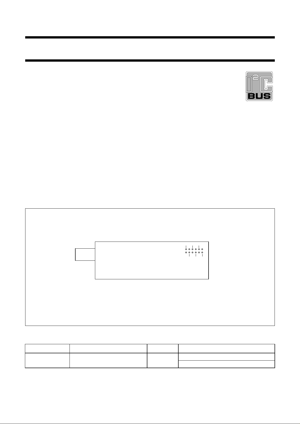
Fig.1 OM5604; OM5606 connector.
2610
4812
159
3711
MBG196
IEC-connector for OM5606
1995 Oct 10 2

Philips Semiconductors Preliminary specification
Multimedia radio tuner OM5604; OM5606
PINNING
PIN DESCRIPTION
1 port 5 PCF8574A (I
2 port 6 PCF8574A (I
3 port 7 PCF8574A (I
4 serial clock input
(1)
5 stereo indicator
6 serial data input/output
7 supply voltage (+5 V)
2
C-bus)
2
C-bus)
2
C-bus)
(1)
INTERFACE
• Digital driving: I2C-bus
• Audio output: typical 900 mV RMS (load 600 Ω) for FM
∆f=75kHz
• Supply: 5 V ±10% current ≤30 mA and 12 V ±1%,
ripple ≤1 V, current ≤2mA
• RDS-MPX: DC coupled (load ≥39 kΩ), amplitude
typical 150 mV (∆f = 75 kHz)
• RF input connector (75 Ω)
• 12 pin connector.
8 supply voltage (+12 V)
9 audio right output
10 ground
11 audio left output
12 MPX signal for RDS demodulation
Note
1. See
“The I2C-bus and how to use it”
(ordering number
9398 393 40011).
LIMITING VALUES
IEC publication 68-1; full specification; EMC behaviour: the module is designed to be FCC friendly (part 15).
SYMBOL PARAMETER CONDITIONS MIN. MAX. UNIT
T temperature 15 35 °C
RH relative humidity 25 85 %
T
amb
T
stg
V
esd(pc)
V
esd(RFc)
operating ambient temperature functional operation −10 +60 °C
storage temperature −20 +70 °C
electrostatic handling for pin
connector
electrostatic handling for
RF-connector
note 1 − 2kV
note 2 − 300 V
note 3 − 4kV
note 4 − 500 V
Notes
1. Class B: human body model (1.5 kΩ, 100 pF).
2. Class B: charge device model (0 Ω, 200 pF).
3. Class A: human body model (1.5 kΩ, 100 pF).
4. Class A: charge device model (0 Ω, 200 pF).
1995 Oct 10 3
 Loading...