

Page 1

OB TraceVue
Title
INSTALLATION AND SERVICE MANUAL
OB TraceVue
Patient Monitoring
M1381-9000Y
4512 610 11101
Software revision D.01.13
Published in Germany 09.2005
Page 2

Notice
Philips makes no warranty of any kind with regard to this material, including, but not limited
to, the implied warranties of merchantability and fitness for a particular purpose. Philips shall
not be liable for errors contained herein or for incidental or consequential damages in connection with the furnishing, performance or use of this material.
This document contains proprietary information that is protected by copyright. All rights are
reserved. No part of this document may be photocopied, reproduced or translated to another
language without prior written consent of Philips.
The information contained in this document is subject to change without notice.
Philips assumes no responsibility for the use or reliability of its software on equipment that
is not furnished by Philips.
Federal Law (US) restricts this device to sale by or on the order of a physician.
Philips developed this system in cooperation with Massachusetts General Hospital, an affiliate of the Harvard Medical School.
Warning
Failure on the part of the responsible individual hospital or institution employing the
use of this equipment to implement a satisfactory maintenance schedule may cause
undue equipment failure and possible health hazards.
Trademarks
Microsoft® is a U.S. registered trademark of Microsoft Corp.
Windows
Corp.
All other product and company names mentioned may be the trademarks of their respective
owners.
®
, Windows NT® and Windows 2000®are U.S. registered trademarks of Microsoft
Acknowledgements
Automated Windows installation developed using AutoIt.
http://www.hiddensoft.com/AutoIt/
© Copyright 1996-2005 Koninklijke Philips Electronics N.V. 92050908
All rights reserved
Page 3

Printing History
Edition .................Part Number ..............OB TraceVue Release................ Print Date
First Edition .........M1381-9000J............. A.02.00 .................................... August 1999
Second Edition..... M1381-9000K ........... B.00.00 ..................................... March 2000
Third Edition........ M1381-9000L............ B.01.00 ...............................September 2000
Fourth Edition...... M1381-9000M........... B.01.00 ..................................... March 2001
Fifth Edition......... M1381-9000N ........... C.00.00 ......................................... July 2001
Sixth Edition ........ M1381-9000P............ C.01.00 ...............................November 2001
Seventh Edition.... M1381-9000Q ...........C.01.01 ..................................... March 2002
Eighth Edition...... M1381-9000R ........... C.01.01 (new PC hardware) ...October 2002
Ninth Edition .......M1381-9000S............ D.00.00 ....................................... April 2003
10th Edition .........M1381-9000T............ D.00.01 ....................................August 2003
11th Edition..........M1381-9000U ...........D.00.02 ................................... January 2004
12th Edition .........M1381-9000V ...........D.01.00 .........................................July 2004
13th Edition .........M1381-9000W .......... D.01.10 .................................... August 2004
14th Edition .........M1381-9000X ...........D.01.11 .................................February 2005
15th Edition .........M1381-9000Y ...........D.01.13 ...............................September 2005
Page 4

Page 5

Contents
Contents
1. Overview . . . . . . . . . . . . . . . . . . . . . . . . . . . . . . . . . . . . . . . . . . . . . . . . . . . . . . . . . . . . . . . . . 1-1
What is OB TraceVue? . . . . . . . . . . . . . . . . . . . . . . . . . . . . . . . . . . . . . . . . . . . . . . . . . . . . . . . . . 1
Who Should Read This Manual . . . . . . . . . . . . . . . . . . . . . . . . . . . . . . . . . . . . . . . . . . . . . . . . . . . . 1
About This Manual . . . . . . . . . . . . . . . . . . . . . . . . . . . . . . . . . . . . . . . . . . . . . . . . . . . . . . . . . . . . 1
Special Tools . . . . . . . . . . . . . . . . . . . . . . . . . . . . . . . . . . . . . . . . . . . . . . . . . . . . . . . . . . . . . . . . 2
Service Packs . . . . . . . . . . . . . . . . . . . . . . . . . . . . . . . . . . . . . . . . . . . . . . . . . . . . . . . . . . . . . . . . 2
Conventions in This Guide . . . . . . . . . . . . . . . . . . . . . . . . . . . . . . . . . . . . . . . . . . . . . . . . . . . . . . . 3
Sterilization and Cleaning . . . . . . . . . . . . . . . . . . . . . . . . . . . . . . . . . . . . . . . . . . . . . . . . . . . . . . . . 3
2. Safety . . . . . . . . . . . . . . . . . . . . . . . . . . . . . . . . . . . . . . . . . . . . . . . . . . . . . . . . . . . . . . . . . . . . 2-1
Introduction . . . . . . . . . . . . . . . . . . . . . . . . . . . . . . . . . . . . . . . . . . . . . . . . . . . . . . . . . . . . . . . . . 1
Symbol Identification. . . . . . . . . . . . . . . . . . . . . . . . . . . . . . . . . . . . . . . . . . . . . . . . . . . . . . . . . . . 1
System Overview . . . . . . . . . . . . . . . . . . . . . . . . . . . . . . . . . . . . . . . . . . . . . . . . . . . . . . . . . . . . . 2
Centralized System . . . . . . . . . . . . . . . . . . . . . . . . . . . . . . . . . . . . . . . . . . . . . . . . . . . . . . . . . 2
Decentralized System . . . . . . . . . . . . . . . . . . . . . . . . . . . . . . . . . . . . . . . . . . . . . . . . . . . . . . . 3
Uninterruptible Power Supply (UPS) . . . . . . . . . . . . . . . . . . . . . . . . . . . . . . . . . . . . . . . . . . . . . 4
PC Power Consumption . . . . . . . . . . . . . . . . . . . . . . . . . . . . . . . . . . . . . . . . . . . . . . . . . . . . . . 4
Safety Test, Verification, and Customer Acceptance Procedures. . . . . . . . . . . . . . . . . . . . . . . . . . . . . . . 5
Test and Inspection Matrix . . . . . . . . . . . . . . . . . . . . . . . . . . . . . . . . . . . . . . . . . . . . . . . . . . . . . . . 6
Safety Test Procedures . . . . . . . . . . . . . . . . . . . . . . . . . . . . . . . . . . . . . . . . . . . . . . . . . . . . . . 11
When to Perform Test Blocks . . . . . . . . . . . . . . . . . . . . . . . . . . . . . . . . . . . . . . . . . . . . . . . . . 15
Safety and Site Preparation . . . . . . . . . . . . . . . . . . . . . . . . . . . . . . . . . . . . . . . . . . . . . . . . . . . . . . 16
Safety Notes for Cabling and Installation . . . . . . . . . . . . . . . . . . . . . . . . . . . . . . . . . . . . . . . . . . . . . 16
Network Verification . . . . . . . . . . . . . . . . . . . . . . . . . . . . . . . . . . . . . . . . . . . . . . . . . . . . . . . . . . 16
Electrostatic Handling Precautions . . . . . . . . . . . . . . . . . . . . . . . . . . . . . . . . . . . . . . . . . . . . . . . . 17
Emissions and Immunity . . . . . . . . . . . . . . . . . . . . . . . . . . . . . . . . . . . . . . . . . . . . . . . . . . . . . . . 17
Guidance and Manufacturer’s Declaration . . . . . . . . . . . . . . . . . . . . . . . . . . . . . . . . . . . . . . . . . 17
Recommended Separation Distances. . . . . . . . . . . . . . . . . . . . . . . . . . . . . . . . . . . . . . . . . . . . . 21
3. Security . . . . . . . . . . . . . . . . . . . . . . . . . . . . . . . . . . . . . . . . . . . . . . . . . . . . . . . . . . . . . . . . . . 3-1
Introduction . . . . . . . . . . . . . . . . . . . . . . . . . . . . . . . . . . . . . . . . . . . . . . . . . . . . . . . . . . . . . . . . 1
Windows Security . . . . . . . . . . . . . . . . . . . . . . . . . . . . . . . . . . . . . . . . . . . . . . . . . . . . . . . . . . . . . 2
Windows User Groups . . . . . . . . . . . . . . . . . . . . . . . . . . . . . . . . . . . . . . . . . . . . . . . . . . . . . . . 2
Windows Users . . . . . . . . . . . . . . . . . . . . . . . . . . . . . . . . . . . . . . . . . . . . . . . . . . . . . . . . . . . 2
Access Rights. . . . . . . . . . . . . . . . . . . . . . . . . . . . . . . . . . . . . . . . . . . . . . . . . . . . . . . . . . . . . 3
Interrupting Auto Login . . . . . . . . . . . . . . . . . . . . . . . . . . . . . . . . . . . . . . . . . . . . . . . . . . . . . . 6
Log On As Windows Administrator . . . . . . . . . . . . . . . . . . . . . . . . . . . . . . . . . . . . . . . . . . . . . . 6
Modifying Access Rights . . . . . . . . . . . . . . . . . . . . . . . . . . . . . . . . . . . . . . . . . . . . . . . . . . . . . 6
4. System Description. . . . . . . . . . . . . . . . . . . . . . . . . . . . . . . . . . . . . . . . . . . . . . . . . . . . . . . . . 4-1
Overview. . . . . . . . . . . . . . . . . . . . . . . . . . . . . . . . . . . . . . . . . . . . . . . . . . . . . . . . . . . . . . . . . . . 1
Centralized Implementation . . . . . . . . . . . . . . . . . . . . . . . . . . . . . . . . . . . . . . . . . . . . . . . . . . . . . . 2
Decentralized Implementation . . . . . . . . . . . . . . . . . . . . . . . . . . . . . . . . . . . . . . . . . . . . . . . . . . . . 2
Shipment Status . . . . . . . . . . . . . . . . . . . . . . . . . . . . . . . . . . . . . . . . . . . . . . . . . . . . . . . . . . . . . . 3
Hardware . . . . . . . . . . . . . . . . . . . . . . . . . . . . . . . . . . . . . . . . . . . . . . . . . . . . . . . . . . . . . . . . . . 4
PCs/Memory . . . . . . . . . . . . . . . . . . . . . . . . . . . . . . . . . . . . . . . . . . . . . . . . . . . . . . . . . . . . . 4
Optical Disk Drives and Medium Changers . . . . . . . . . . . . . . . . . . . . . . . . . . . . . . . . . . . . . . . . . 5
Displays . . . . . . . . . . . . . . . . . . . . . . . . . . . . . . . . . . . . . . . . . . . . . . . . . . . . . . . . . . . . . . . . 5
Software Components . . . . . . . . . . . . . . . . . . . . . . . . . . . . . . . . . . . . . . . . . . . . . . . . . . . . . . . . . . 6
OB TraceVue . . . . . . . . . . . . . . . . . . . . . . . . . . . . . . . . . . . . . . . . . . . . . . . . . . . . . . . . . . . . 6
Contents-1
Page 6

Third Party Software
Wall Cabling and Faceplates . . . . . . . . . . . . . . . . . . . . . . . . . . . . . . . . . . . . . . . . . . . . . . . . . . . . . 7
System Limitations . . . . . . . . . . . . . . . . . . . . . . . . . . . . . . . . . . . . . . . . . . . . . . . . . . . . . . . . . . . . 8
Power . . . . . . . . . . . . . . . . . . . . . . . . . . . . . . . . . . . . . . . . . . . . . . . . . . . . . . . . . . . . . . . . . . 8
PCs and Fetal Monitors . . . . . . . . . . . . . . . . . . . . . . . . . . . . . . . . . . . . . . . . . . . . . . . . . . . . . . 8
Serial Port Servers . . . . . . . . . . . . . . . . . . . . . . . . . . . . . . . . . . . . . . . . . . . . . . . . . . . . . . . . . . 9
Modems . . . . . . . . . . . . . . . . . . . . . . . . . . . . . . . . . . . . . . . . . . . . . . . . . . . . . . . . . . . . . . . . 9
Interfacing . . . . . . . . . . . . . . . . . . . . . . . . . . . . . . . . . . . . . . . . . . . . . . . . . . . . . . . . . . . . . . 10
Network . . . . . . . . . . . . . . . . . . . . . . . . . . . . . . . . . . . . . . . . . . . . . . . . . . . . . . . . . . . . . . . 10
OBMS Retrieval . . . . . . . . . . . . . . . . . . . . . . . . . . . . . . . . . . . . . . . . . . . . . . . . . . . . . . . . . . 10
Documentation . . . . . . . . . . . . . . . . . . . . . . . . . . . . . . . . . . . . . . . . . . . . . . . . . . . . . . . . . . . . . . 11
. . . . . . . . . . . . . . . . . . . . . . . . . . . . . . . . . . . . . . . . . . . . . . . . . . . . . . . . 6
5. New System Setup . . . . . . . . . . . . . . . . . . . . . . . . . . . . . . . . . . . . . . . . . . . . . . . . . . . . . . . . .5-1
Introduction . . . . . . . . . . . . . . . . . . . . . . . . . . . . . . . . . . . . . . . . . . . . . . . . . . . . . . . . . . . . . . . . . 1
PC Types. . . . . . . . . . . . . . . . . . . . . . . . . . . . . . . . . . . . . . . . . . . . . . . . . . . . . . . . . . . . . . . . 1
Order in which to Perform Tasks . . . . . . . . . . . . . . . . . . . . . . . . . . . . . . . . . . . . . . . . . . . . . . . . 1
Installation Checklists . . . . . . . . . . . . . . . . . . . . . . . . . . . . . . . . . . . . . . . . . . . . . . . . . . . . . . . . . . 2
Tasks . . . . . . . . . . . . . . . . . . . . . . . . . . . . . . . . . . . . . . . . . . . . . . . . . . . . . . . . . . . . . . . . . . . . 13
WEB Clients . . . . . . . . . . . . . . . . . . . . . . . . . . . . . . . . . . . . . . . . . . . . . . . . . . . . . . . . . . . . . . . 35
Starting a WEB Client . . . . . . . . . . . . . . . . . . . . . . . . . . . . . . . . . . . . . . . . . . . . . . . . . . . . . . 35
Real-Time WEB Client . . . . . . . . . . . . . . . . . . . . . . . . . . . . . . . . . . . . . . . . . . . . . . . . . . . . . 35
6. Setup Details . . . . . . . . . . . . . . . . . . . . . . . . . . . . . . . . . . . . . . . . . . . . . . . . . . . . . . . . . . . . . .6-1
Introduction . . . . . . . . . . . . . . . . . . . . . . . . . . . . . . . . . . . . . . . . . . . . . . . . . . . . . . . . . . . . . . . . . 1
Installing a Client on a Cart (Mobile Client) . . . . . . . . . . . . . . . . . . . . . . . . . . . . . . . . . . . . . . . . . . . . 1
Telemetry Unit . . . . . . . . . . . . . . . . . . . . . . . . . . . . . . . . . . . . . . . . . . . . . . . . . . . . . . . . . . . 1
Client UPS . . . . . . . . . . . . . . . . . . . . . . . . . . . . . . . . . . . . . . . . . . . . . . . . . . . . . . . . . . . . . . . 1
Configuration . . . . . . . . . . . . . . . . . . . . . . . . . . . . . . . . . . . . . . . . . . . . . . . . . . . . . . . . . . . . . 2
Moving the Cart . . . . . . . . . . . . . . . . . . . . . . . . . . . . . . . . . . . . . . . . . . . . . . . . . . . . . . . . . . 2
Connecting Fetal Monitors . . . . . . . . . . . . . . . . . . . . . . . . . . . . . . . . . . . . . . . . . . . . . . . . . . . . . . . 3
M1350, M1351/53 and Avalon FM20/FM30 Monitors . . . . . . . . . . . . . . . . . . . . . . . . . . . . . . . . . . 3
Other Fetal Monitors . . . . . . . . . . . . . . . . . . . . . . . . . . . . . . . . . . . . . . . . . . . . . . . . . . . . . . . . 3
Network Type. . . . . . . . . . . . . . . . . . . . . . . . . . . . . . . . . . . . . . . . . . . . . . . . . . . . . . . . . . . . . 3
Connecting Four Fetal Monitors . . . . . . . . . . . . . . . . . . . . . . . . . . . . . . . . . . . . . . . . . . . . . . . . 4
Connecting More than Four Fetal Monitors . . . . . . . . . . . . . . . . . . . . . . . . . . . . . . . . . . . . . . . . . 4
Protocol Conversion . . . . . . . . . . . . . . . . . . . . . . . . . . . . . . . . . . . . . . . . . . . . . . . . . . . . . . . . 4
Hewlett-Packard / Agilent / Philips Fetal Monitors. . . . . . . . . . . . . . . . . . . . . . . . . . . . . . . . . . . . . 5
Connecting to the Network . . . . . . . . . . . . . . . . . . . . . . . . . . . . . . . . . . . . . . . . . . . . . . . . . . . . . . . 8
Network Connections. . . . . . . . . . . . . . . . . . . . . . . . . . . . . . . . . . . . . . . . . . . . . . . . . . . . . . . . 8
Hubs and Switches . . . . . . . . . . . . . . . . . . . . . . . . . . . . . . . . . . . . . . . . . . . . . . . . . . . . . . . . . 8
Network Specifications. . . . . . . . . . . . . . . . . . . . . . . . . . . . . . . . . . . . . . . . . . . . . . . . . . . . . . . 9
Cable Specifications . . . . . . . . . . . . . . . . . . . . . . . . . . . . . . . . . . . . . . . . . . . . . . . . . . . . . . . 11
Cabling a LAN . . . . . . . . . . . . . . . . . . . . . . . . . . . . . . . . . . . . . . . . . . . . . . . . . . . . . . . . 13
Installing and Configuring Remote LAN Clients . . . . . . . . . . . . . . . . . . . . . . . . . . . . . . . . . . . . . . . . 16
Limitations and Prerequisites . . . . . . . . . . . . . . . . . . . . . . . . . . . . . . . . . . . . . . . . . . . . . . . . . . 16
Installation and Configuration . . . . . . . . . . . . . . . . . . . . . . . . . . . . . . . . . . . . . . . . . . . . . . . . . 16
Patient Search Tool Network Configuration . . . . . . . . . . . . . . . . . . . . . . . . . . . . . . . . . . . . . . . . . . . 19
Network Connection . . . . . . . . . . . . . . . . . . . . . . . . . . . . . . . . . . . . . . . . . . . . . . . . . . . . . . . 19
Configuration . . . . . . . . . . . . . . . . . . . . . . . . . . . . . . . . . . . . . . . . . . . . . . . . . . . . . . . . . . . . 20
Installing and Setting up a Serial Port Server . . . . . . . . . . . . . . . . . . . . . . . . . . . . . . . . . . . . . . . . . . 22
Contents-2
Page 7

Introduction
Host PC Network Settings . . . . . . . . . . . . . . . . . . . . . . . . . . . . . . . . . . . . . . . . . . . . . . . . . . . 24
Connect Port Server. . . . . . . . . . . . . . . . . . . . . . . . . . . . . . . . . . . . . . . . . . . . . . . . . . . . . . . . 25
Port Server Network Settings. . . . . . . . . . . . . . . . . . . . . . . . . . . . . . . . . . . . . . . . . . . . . . . . . . 26
Install Software . . . . . . . . . . . . . . . . . . . . . . . . . . . . . . . . . . . . . . . . . . . . . . . . . . . . . . . . . . 28
Configure Serial Port Server . . . . . . . . . . . . . . . . . . . . . . . . . . . . . . . . . . . . . . . . . . . . . . . . . . 29
Configure OB TraceVue . . . . . . . . . . . . . . . . . . . . . . . . . . . . . . . . . . . . . . . . . . . . . . . . . . . . 34
Connect Fetal Monitors . . . . . . . . . . . . . . . . . . . . . . . . . . . . . . . . . . . . . . . . . . . . . . . . . . . . . 34
Check Fetal Monitor to Bed Connection . . . . . . . . . . . . . . . . . . . . . . . . . . . . . . . . . . . . . . . . . . 34
Using the Serial Port Server at a Different PC. . . . . . . . . . . . . . . . . . . . . . . . . . . . . . . . . . . . . . . 35
Replacing a Serial Port Server . . . . . . . . . . . . . . . . . . . . . . . . . . . . . . . . . . . . . . . . . . . . . . . . . 36
Setting Up a Printer . . . . . . . . . . . . . . . . . . . . . . . . . . . . . . . . . . . . . . . . . . . . . . . . . . . . . . . . . . . 41
General Printer Setup Procedures . . . . . . . . . . . . . . . . . . . . . . . . . . . . . . . . . . . . . . . . . . . . . . . 42
Printer Connected to a PC’s Parallel Port . . . . . . . . . . . . . . . . . . . . . . . . . . . . . . . . . . . . . . . . . . 42
Printer Connected to the Network using a HP JetDirect Card . . . . . . . . . . . . . . . . . . . . . . . . . . . . . 43
Printing on WEB Client PCs . . . . . . . . . . . . . . . . . . . . . . . . . . . . . . . . . . . . . . . . . . . . . . . . . . 45
Setting Up Remote Connectivity . . . . . . . . . . . . . . . . . . . . . . . . . . . . . . . . . . . . . . . . . . . . . . . . . . 46
Setting up Remote Trace Transmission . . . . . . . . . . . . . . . . . . . . . . . . . . . . . . . . . . . . . . . . . . . 46
Setting up Web Access Through Dial-Up Modem . . . . . . . . . . . . . . . . . . . . . . . . . . . . . . . . . . . . 46
Setting up Remote Access Support . . . . . . . . . . . . . . . . . . . . . . . . . . . . . . . . . . . . . . . . . . . . . . 46
Setting Up Fax Transmission. . . . . . . . . . . . . . . . . . . . . . . . . . . . . . . . . . . . . . . . . . . . . . . . . . 47
Installing a Modem . . . . . . . . . . . . . . . . . . . . . . . . . . . . . . . . . . . . . . . . . . . . . . . . . . . . . . . . 48
Installing Microsoft Office 2003 . . . . . . . . . . . . . . . . . . . . . . . . . . . . . . . . . . . . . . . . . . . . . . . . . . 50
Install Software . . . . . . . . . . . . . . . . . . . . . . . . . . . . . . . . . . . . . . . . . . . . . . . . . . . . . . . . . . 50
Installation Tasks . . . . . . . . . . . . . . . . . . . . . . . . . . . . . . . . . . . . . . . . . . . . . . . . . . . . . . . . . 52
Installing Word and Excel Templates . . . . . . . . . . . . . . . . . . . . . . . . . . . . . . . . . . . . . . . . . . . . . . . 53
Overview. . . . . . . . . . . . . . . . . . . . . . . . . . . . . . . . . . . . . . . . . . . . . . . . . . . . . . . . . . . . . . . 53
New Installation . . . . . . . . . . . . . . . . . . . . . . . . . . . . . . . . . . . . . . . . . . . . . . . . . . . . . . . . . . 55
. . . . . . . . . . . . . . . . . . . . . . . . . . . . . . . . . . . . . . . . . . . . . . . . . . . . . . . . . . . . . 22
7. Troubleshooting . . . . . . . . . . . . . . . . . . . . . . . . . . . . . . . . . . . . . . . . . . . . . . . . . . . . . . . . . . . 7-1
Networking and System Setup Problems . . . . . . . . . . . . . . . . . . . . . . . . . . . . . . . . . . . . . . . . . . . . . . 1
Hardware Problems . . . . . . . . . . . . . . . . . . . . . . . . . . . . . . . . . . . . . . . . . . . . . . . . . . . . . . . . . . . . 4
Fetal Monitor Connection / Data Acquisition Problems . . . . . . . . . . . . . . . . . . . . . . . . . . . . . . . . . . . . 6
Application problems. . . . . . . . . . . . . . . . . . . . . . . . . . . . . . . . . . . . . . . . . . . . . . . . . . . . . . . . . . . 7
8. Maintenance . . . . . . . . . . . . . . . . . . . . . . . . . . . . . . . . . . . . . . . . . . . . . . . . . . . . . . . . . . . . . . 8-1
Introduction . . . . . . . . . . . . . . . . . . . . . . . . . . . . . . . . . . . . . . . . . . . . . . . . . . . . . . . . . . . . . . . . . 1
Recommended Maintenance . . . . . . . . . . . . . . . . . . . . . . . . . . . . . . . . . . . . . . . . . . . . . . . . . . . . . . 1
Caring for Optical Drives and Media. . . . . . . . . . . . . . . . . . . . . . . . . . . . . . . . . . . . . . . . . . . . . . . . . 3
Caring for Optical Drives (standalone drives only) . . . . . . . . . . . . . . . . . . . . . . . . . . . . . . . . . . . . 3
Caring for Optical Disks . . . . . . . . . . . . . . . . . . . . . . . . . . . . . . . . . . . . . . . . . . . . . . . . . . . . . . 3
Rebooting the WEB/Terminal Server . . . . . . . . . . . . . . . . . . . . . . . . . . . . . . . . . . . . . . . . . . . . . . . . 4
Virus Protection . . . . . . . . . . . . . . . . . . . . . . . . . . . . . . . . . . . . . . . . . . . . . . . . . . . . . . . . . . . . . . 4
External Database Performance . . . . . . . . . . . . . . . . . . . . . . . . . . . . . . . . . . . . . . . . . . . . . . . . . . . . 5
9. System Support . . . . . . . . . . . . . . . . . . . . . . . . . . . . . . . . . . . . . . . . . . . . . . . . . . . . . . . . . . . 9-1
Overview. . . . . . . . . . . . . . . . . . . . . . . . . . . . . . . . . . . . . . . . . . . . . . . . . . . . . . . . . . . . . . . . . . . 1
System Overview Tool. . . . . . . . . . . . . . . . . . . . . . . . . . . . . . . . . . . . . . . . . . . . . . . . . . . . . . . . . . 2
Restrictions . . . . . . . . . . . . . . . . . . . . . . . . . . . . . . . . . . . . . . . . . . . . . . . . . . . . . . . . . . . . . . 2
Using with OB TraceVue Remote LAN Clients . . . . . . . . . . . . . . . . . . . . . . . . . . . . . . . . . . . . . . 2
Contents-3
Page 8

Remote Support Using Terminal Services
Overview. . . . . . . . . . . . . . . . . . . . . . . . . . . . . . . . . . . . . . . . . . . . . . . . . . . . . . . . . . . . . . . . 3
Enabling Terminal Services Server Remote Support on a Server PC . . . . . . . . . . . . . . . . . . . . . . . . . 4
Modem Setup . . . . . . . . . . . . . . . . . . . . . . . . . . . . . . . . . . . . . . . . . . . . . . . . . . . . . . . . . . . . . 4
Installing Terminal Services Client . . . . . . . . . . . . . . . . . . . . . . . . . . . . . . . . . . . . . . . . . . . . . . . 4
Using Terminal Services Client . . . . . . . . . . . . . . . . . . . . . . . . . . . . . . . . . . . . . . . . . . . . . . . . . 5
Log Files . . . . . . . . . . . . . . . . . . . . . . . . . . . . . . . . . . . . . . . . . . . . . . . . . . . . . . . . . . . . . . . . . . . 6
HP TopTools Management Software. . . . . . . . . . . . . . . . . . . . . . . . . . . . . . . . . . . . . . . . . . . . . . . . . 8
HP / Compaq Insight Management Software. . . . . . . . . . . . . . . . . . . . . . . . . . . . . . . . . . . . . . . . . . . . 9
Introduction . . . . . . . . . . . . . . . . . . . . . . . . . . . . . . . . . . . . . . . . . . . . . . . . . . . . . . . . . . . . . . 9
Management Agents . . . . . . . . . . . . . . . . . . . . . . . . . . . . . . . . . . . . . . . . . . . . . . . . . . . . . . . . 9
HP / Compaq Insight Manager 7 SP2 . . . . . . . . . . . . . . . . . . . . . . . . . . . . . . . . . . . . . . . . . . . . . 9
HP Insight Diagnostics Online Edition for Windows . . . . . . . . . . . . . . . . . . . . . . . . . . . . . . . . . . . 9
. . . . . . . . . . . . . . . . . . . . . . . . . . . . . . . . . . . . . . . . . . . . . 3
10. Configuration Verification Procedure . . . . . . . . . . . . . . . . . . . . . . . . . . . . . . . . . . . . . . .10-1
Customer Verification . . . . . . . . . . . . . . . . . . . . . . . . . . . . . . . . . . . . . . . . . . . . . . . . . . . . . . . . . . 1
Configuration Verification . . . . . . . . . . . . . . . . . . . . . . . . . . . . . . . . . . . . . . . . . . . . . . . . . . . . . . . 1
11. Repairing/Replacing Hardware and Media. . . . . . . . . . . . . . . . . . . . . . . . . . . . . . . . . . . 11-1
Repair Strategy . . . . . . . . . . . . . . . . . . . . . . . . . . . . . . . . . . . . . . . . . . . . . . . . . . . . . . . . . . . . . . . 1
Hardware Defects . . . . . . . . . . . . . . . . . . . . . . . . . . . . . . . . . . . . . . . . . . . . . . . . . . . . . . . . . . 1
Substituting a PC. . . . . . . . . . . . . . . . . . . . . . . . . . . . . . . . . . . . . . . . . . . . . . . . . . . . . . . . . . . 3
Software Media Defects . . . . . . . . . . . . . . . . . . . . . . . . . . . . . . . . . . . . . . . . . . . . . . . . . . . . . . 3
Parts Stocking . . . . . . . . . . . . . . . . . . . . . . . . . . . . . . . . . . . . . . . . . . . . . . . . . . . . . . . . . . . . . . . 4
Fetal Monitor Connections . . . . . . . . . . . . . . . . . . . . . . . . . . . . . . . . . . . . . . . . . . . . . . . . . . . . 4
Power Supply . . . . . . . . . . . . . . . . . . . . . . . . . . . . . . . . . . . . . . . . . . . . . . . . . . . . . . . . . . . . . 4
Accessories . . . . . . . . . . . . . . . . . . . . . . . . . . . . . . . . . . . . . . . . . . . . . . . . . . . . . . . . . . . . . . 5
Cabling . . . . . . . . . . . . . . . . . . . . . . . . . . . . . . . . . . . . . . . . . . . . . . . . . . . . . . . . . . . . . . . . . 6
Modems . . . . . . . . . . . . . . . . . . . . . . . . . . . . . . . . . . . . . . . . . . . . . . . . . . . . . . . . . . . . . . . . 6
Hubs/Switches . . . . . . . . . . . . . . . . . . . . . . . . . . . . . . . . . . . . . . . . . . . . . . . . . . . . . . . . . . . . 7
Serial Port Servers . . . . . . . . . . . . . . . . . . . . . . . . . . . . . . . . . . . . . . . . . . . . . . . . . . . . . . . . . . 8
Tape Drives . . . . . . . . . . . . . . . . . . . . . . . . . . . . . . . . . . . . . . . . . . . . . . . . . . . . . . . . . . . . . . 9
Optical Drives . . . . . . . . . . . . . . . . . . . . . . . . . . . . . . . . . . . . . . . . . . . . . . . . . . . . . . . . . . . 10
Jukebox/Autochanger. . . . . . . . . . . . . . . . . . . . . . . . . . . . . . . . . . . . . . . . . . . . . . . . . . . . . . . 11
Displays . . . . . . . . . . . . . . . . . . . . . . . . . . . . . . . . . . . . . . . . . . . . . . . . . . . . . . . . . . . . . . . 12
Kayak XA . . . . . . . . . . . . . . . . . . . . . . . . . . . . . . . . . . . . . . . . . . . . . . . . . . . . . . . . . . . . . . 14
Vectra VL400. . . . . . . . . . . . . . . . . . . . . . . . . . . . . . . . . . . . . . . . . . . . . . . . . . . . . . . . . . . . 15
Vectra VL420. . . . . . . . . . . . . . . . . . . . . . . . . . . . . . . . . . . . . . . . . . . . . . . . . . . . . . . . . . . . 16
Compaq Evo D510 . . . . . . . . . . . . . . . . . . . . . . . . . . . . . . . . . . . . . . . . . . . . . . . . . . . . . . . . 17
Compaq D530 . . . . . . . . . . . . . . . . . . . . . . . . . . . . . . . . . . . . . . . . . . . . . . . . . . . . . . . . . . . 19
Compaq dc7100 . . . . . . . . . . . . . . . . . . . . . . . . . . . . . . . . . . . . . . . . . . . . . . . . . . . . . . . . . . 20
Compaq dc7600 . . . . . . . . . . . . . . . . . . . . . . . . . . . . . . . . . . . . . . . . . . . . . . . . . . . . . . . . . . 21
NetServer LC2000. . . . . . . . . . . . . . . . . . . . . . . . . . . . . . . . . . . . . . . . . . . . . . . . . . . . . . . . . 22
Compaq ProLiant ML370 . . . . . . . . . . . . . . . . . . . . . . . . . . . . . . . . . . . . . . . . . . . . . . . . . . . . 23
HP Proliant ML350 . . . . . . . . . . . . . . . . . . . . . . . . . . . . . . . . . . . . . . . . . . . . . . . . . . . . . . . . 25
PC Common Parts . . . . . . . . . . . . . . . . . . . . . . . . . . . . . . . . . . . . . . . . . . . . . . . . . . . . . . . . . 27
SW Media and Documentation. . . . . . . . . . . . . . . . . . . . . . . . . . . . . . . . . . . . . . . . . . . . . . . . . 29
UPS Parts . . . . . . . . . . . . . . . . . . . . . . . . . . . . . . . . . . . . . . . . . . . . . . . . . . . . . . . . . . . . . . 30
12. Component Installation (Upgrade/repair) . . . . . . . . . . . . . . . . . . . . . . . . . . . . . . . . . . . .12-1
Contents-4
Page 9

Introduction
Software Distribution. . . . . . . . . . . . . . . . . . . . . . . . . . . . . . . . . . . . . . . . . . . . . . . . . . . . . . . . . . . 1
PC System Board Replacement . . . . . . . . . . . . . . . . . . . . . . . . . . . . . . . . . . . . . . . . . . . . . . . . . . . . 2
Additional Memory . . . . . . . . . . . . . . . . . . . . . . . . . . . . . . . . . . . . . . . . . . . . . . . . . . . . . . . . . . . 2
Lightpen Interface Board . . . . . . . . . . . . . . . . . . . . . . . . . . . . . . . . . . . . . . . . . . . . . . . . . . . . . . . . 2
Slot Assignment . . . . . . . . . . . . . . . . . . . . . . . . . . . . . . . . . . . . . . . . . . . . . . . . . . . . . . . . . . . 2
M1370-66510 only . . . . . . . . . . . . . . . . . . . . . . . . . . . . . . . . . . . . . . . . . . . . . . . . . . . . . . . . . 2
Connecting and Fitting . . . . . . . . . . . . . . . . . . . . . . . . . . . . . . . . . . . . . . . . . . . . . . . . . . . . . . . 2
Soundcard and Loudspeaker . . . . . . . . . . . . . . . . . . . . . . . . . . . . . . . . . . . . . . . . . . . . . . . . . . . . . . 3
Installation. . . . . . . . . . . . . . . . . . . . . . . . . . . . . . . . . . . . . . . . . . . . . . . . . . . . . . . . . . . . . . . 3
Volume . . . . . . . . . . . . . . . . . . . . . . . . . . . . . . . . . . . . . . . . . . . . . . . . . . . . . . . . . . . . . . . . . 3
Network Interface (LAN) Card . . . . . . . . . . . . . . . . . . . . . . . . . . . . . . . . . . . . . . . . . . . . . . . . . . . . 4
PCI RS-232 Serial I/F Card M1380-66501 (for all PCs except dc7600) . . . . . . . . . . . . . . . . . . . . . . . . . . 4
Fitting the PCI RS-232 Serial Interface Card . . . . . . . . . . . . . . . . . . . . . . . . . . . . . . . . . . . . . . . . 4
Using FMSpy to Test the COM Ports . . . . . . . . . . . . . . . . . . . . . . . . . . . . . . . . . . . . . . . . . . . . . 4
CD-ROM Drive . . . . . . . . . . . . . . . . . . . . . . . . . . . . . . . . . . . . . . . . . . . . . . . . . . . . . . . . . . . . . . 5
Primary Hard Disk Drive . . . . . . . . . . . . . . . . . . . . . . . . . . . . . . . . . . . . . . . . . . . . . . . . . . . . . . . . 5
SCSI Host Adapter . . . . . . . . . . . . . . . . . . . . . . . . . . . . . . . . . . . . . . . . . . . . . . . . . . . . . . . . . . . . 7
Host Adapter Types. . . . . . . . . . . . . . . . . . . . . . . . . . . . . . . . . . . . . . . . . . . . . . . . . . . . . . . . . 7
Slot Assignment . . . . . . . . . . . . . . . . . . . . . . . . . . . . . . . . . . . . . . . . . . . . . . . . . . . . . . . . . . . 7
SCSI BIOS . . . . . . . . . . . . . . . . . . . . . . . . . . . . . . . . . . . . . . . . . . . . . . . . . . . . . . . . . . . . . . 8
Secondary Hard Disk Drive (for Storage Systems). . . . . . . . . . . . . . . . . . . . . . . . . . . . . . . . . . . . . . . . 8
Disk Installation . . . . . . . . . . . . . . . . . . . . . . . . . . . . . . . . . . . . . . . . . . . . . . . . . . . . . . . . . . . 8
Windows Installation . . . . . . . . . . . . . . . . . . . . . . . . . . . . . . . . . . . . . . . . . . . . . . . . . . . . . . . 10
Optical Drives . . . . . . . . . . . . . . . . . . . . . . . . . . . . . . . . . . . . . . . . . . . . . . . . . . . . . . . . . . . . . . 11
Optical Medium Changers (Jukeboxes) . . . . . . . . . . . . . . . . . . . . . . . . . . . . . . . . . . . . . . . . . . . . . . 12
Optical Disk Drive Cabinet . . . . . . . . . . . . . . . . . . . . . . . . . . . . . . . . . . . . . . . . . . . . . . . . . . . . . . 14
Before Installing the Optical Disk Drive Cabinet . . . . . . . . . . . . . . . . . . . . . . . . . . . . . . . . . . . . . 14
Installing the Optical Disk Drive Cabinet . . . . . . . . . . . . . . . . . . . . . . . . . . . . . . . . . . . . . . . . . . 15
Maintenance . . . . . . . . . . . . . . . . . . . . . . . . . . . . . . . . . . . . . . . . . . . . . . . . . . . . . . . . . . . . 15
Repair. . . . . . . . . . . . . . . . . . . . . . . . . . . . . . . . . . . . . . . . . . . . . . . . . . . . . . . . . . . . . . . . . 15
Backup Device (External Server Only) . . . . . . . . . . . . . . . . . . . . . . . . . . . . . . . . . . . . . . . . . . . . . . 16
High-End External Server (RAID) . . . . . . . . . . . . . . . . . . . . . . . . . . . . . . . . . . . . . . . . . . . . . . 16
Standard External Server . . . . . . . . . . . . . . . . . . . . . . . . . . . . . . . . . . . . . . . . . . . . . . . . . . . . 16
UPS . . . . . . . . . . . . . . . . . . . . . . . . . . . . . . . . . . . . . . . . . . . . . . . . . . . . . . . . . . . . . . . . . . . . . 18
Overview. . . . . . . . . . . . . . . . . . . . . . . . . . . . . . . . . . . . . . . . . . . . . . . . . . . . . . . . . . . . . . . 18
Connecting the UPS . . . . . . . . . . . . . . . . . . . . . . . . . . . . . . . . . . . . . . . . . . . . . . . . . . . . . . . 19
UPS Driver Software . . . . . . . . . . . . . . . . . . . . . . . . . . . . . . . . . . . . . . . . . . . . . . . . . . . . . . . 19
Disk Identification (Kayak XU only) . . . . . . . . . . . . . . . . . . . . . . . . . . . . . . . . . . . . . . . . . . . . . . . 20
. . . . . . . . . . . . . . . . . . . . . . . . . . . . . . . . . . . . . . . . . . . . . . . . . . . . . . . . . . . . . . . . . 1
13. Renaming a PC. . . . . . . . . . . . . . . . . . . . . . . . . . . . . . . . . . . . . . . . . . . . . . . . . . . . . . . . . . 13-1
Changing a Server PC Name . . . . . . . . . . . . . . . . . . . . . . . . . . . . . . . . . . . . . . . . . . . . . . . . . . . . . . 1
Changing a Client PC Name . . . . . . . . . . . . . . . . . . . . . . . . . . . . . . . . . . . . . . . . . . . . . . . . . . . . . . 1
Replacement Client . . . . . . . . . . . . . . . . . . . . . . . . . . . . . . . . . . . . . . . . . . . . . . . . . . . . . . . . . . . . 2
14. Tools . . . . . . . . . . . . . . . . . . . . . . . . . . . . . . . . . . . . . . . . . . . . . . . . . . . . . . . . . . . . . . . . . .14-1
Overview. . . . . . . . . . . . . . . . . . . . . . . . . . . . . . . . . . . . . . . . . . . . . . . . . . . . . . . . . . . . . . . . . . . 1
Standard Windows Tools . . . . . . . . . . . . . . . . . . . . . . . . . . . . . . . . . . . . . . . . . . . . . . . . . . . . . 1
Database Tools . . . . . . . . . . . . . . . . . . . . . . . . . . . . . . . . . . . . . . . . . . . . . . . . . . . . . . . . . . . . 2
OB TraceVue Tools . . . . . . . . . . . . . . . . . . . . . . . . . . . . . . . . . . . . . . . . . . . . . . . . . . . . . . . . 3
Contents-5
Page 10

Other Tools
Windows Tools. . . . . . . . . . . . . . . . . . . . . . . . . . . . . . . . . . . . . . . . . . . . . . . . . . . . . . . . . . . . . . . 6
Disk Defragmenter . . . . . . . . . . . . . . . . . . . . . . . . . . . . . . . . . . . . . . . . . . . . . . . . . . . . . . . . . 6
OB TraceVue Tools . . . . . . . . . . . . . . . . . . . . . . . . . . . . . . . . . . . . . . . . . . . . . . . . . . . . . . . . . . . 7
Administration Tool . . . . . . . . . . . . . . . . . . . . . . . . . . . . . . . . . . . . . . . . . . . . . . . . . . . . . . . . 7
Database Rebuild Tool . . . . . . . . . . . . . . . . . . . . . . . . . . . . . . . . . . . . . . . . . . . . . . . . . . . . . . . 8
Offline Backup Tool . . . . . . . . . . . . . . . . . . . . . . . . . . . . . . . . . . . . . . . . . . . . . . . . . . . . . . . 10
LogFile Viewer for OB TraceVue Error Logs . . . . . . . . . . . . . . . . . . . . . . . . . . . . . . . . . . . . . . 12
Installation Record . . . . . . . . . . . . . . . . . . . . . . . . . . . . . . . . . . . . . . . . . . . . . . . . . . . . . . . . 14
Fetal Monitor Spy (FMSpy) . . . . . . . . . . . . . . . . . . . . . . . . . . . . . . . . . . . . . . . . . . . . . . . . . . 14
Tools Available from the Softserver . . . . . . . . . . . . . . . . . . . . . . . . . . . . . . . . . . . . . . . . . . . . . . . . 18
Downloading from Softserver . . . . . . . . . . . . . . . . . . . . . . . . . . . . . . . . . . . . . . . . . . . . . . . . . 18
DiagTools . . . . . . . . . . . . . . . . . . . . . . . . . . . . . . . . . . . . . . . . . . . . . . . . . . . . . . . . . . . . . . 19
GetLog . . . . . . . . . . . . . . . . . . . . . . . . . . . . . . . . . . . . . . . . . . . . . . . . . . . . . . . . . . . . . . . . 20
. . . . . . . . . . . . . . . . . . . . . . . . . . . . . . . . . . . . . . . . . . . . . . . . . . . . . . . . . . . . . . 5
15. OB TraceVue Repair . . . . . . . . . . . . . . . . . . . . . . . . . . . . . . . . . . . . . . . . . . . . . . . . . . . . .15-1
What to do if . . . . . . . . . . . . . . . . . . . . . . . . . . . . . . . . . . . . . . . . . . . . . . . . . . . . . . . . . . . . . . . . 1
Which Tool? . . . . . . . . . . . . . . . . . . . . . . . . . . . . . . . . . . . . . . . . . . . . . . . . . . . . . . . . . . . . . . . . 3
Recovery Process After a Hardware Failure or System Software Failure . . . . . . . . . . . . . . . . . . . . . . . . . 4
Recovery Process: Internal Server with RAID Disk Array . . . . . . . . . . . . . . . . . . . . . . . . . . . . . . . . 4
Recovery Process: Internal Server with Archiving (no RAID) . . . . . . . . . . . . . . . . . . . . . . . . . . . . . 7
Recovery Process: Internal Server without Archiving . . . . . . . . . . . . . . . . . . . . . . . . . . . . . . . . . . 10
Recovery Process: External Database Server . . . . . . . . . . . . . . . . . . . . . . . . . . . . . . . . . . . . . . . 11
Recovery Process: WEB/Terminal Server . . . . . . . . . . . . . . . . . . . . . . . . . . . . . . . . . . . . . . . . . 11
Recovery Process: Client . . . . . . . . . . . . . . . . . . . . . . . . . . . . . . . . . . . . . . . . . . . . . . . . . . . . 12
Local Data Recovery Tool . . . . . . . . . . . . . . . . . . . . . . . . . . . . . . . . . . . . . . . . . . . . . . . . . . . . . . 13
Using the Local Data Recovery Tool. . . . . . . . . . . . . . . . . . . . . . . . . . . . . . . . . . . . . . . . . . . . . 13
Data Recovery Process . . . . . . . . . . . . . . . . . . . . . . . . . . . . . . . . . . . . . . . . . . . . . . . . . . . . . . 14
Link Recovery Tool . . . . . . . . . . . . . . . . . . . . . . . . . . . . . . . . . . . . . . . . . . . . . . . . . . . . . . . . . . . 17
When to Use the Link Recovery Tool . . . . . . . . . . . . . . . . . . . . . . . . . . . . . . . . . . . . . . . . . . . . 17
Prerequisites. . . . . . . . . . . . . . . . . . . . . . . . . . . . . . . . . . . . . . . . . . . . . . . . . . . . . . . . . . . . . 17
Using the Link Recovery Tool . . . . . . . . . . . . . . . . . . . . . . . . . . . . . . . . . . . . . . . . . . . . . . . . . 18
Configuration Backup (Internal Server Only) . . . . . . . . . . . . . . . . . . . . . . . . . . . . . . . . . . . . . . . . . . 20
Preconditions . . . . . . . . . . . . . . . . . . . . . . . . . . . . . . . . . . . . . . . . . . . . . . . . . . . . . . . . . . . . 20
Using the Configuration Backup . . . . . . . . . . . . . . . . . . . . . . . . . . . . . . . . . . . . . . . . . . . . . . . 20
Optical Disk Test Tool . . . . . . . . . . . . . . . . . . . . . . . . . . . . . . . . . . . . . . . . . . . . . . . . . . . . . . . . . 22
Requirements . . . . . . . . . . . . . . . . . . . . . . . . . . . . . . . . . . . . . . . . . . . . . . . . . . . . . . . . . . . . 22
Using the Disk Test Tool . . . . . . . . . . . . . . . . . . . . . . . . . . . . . . . . . . . . . . . . . . . . . . . . . . . . 23
Low Level Check . . . . . . . . . . . . . . . . . . . . . . . . . . . . . . . . . . . . . . . . . . . . . . . . . . . . . . . . . 24
Disk Copy . . . . . . . . . . . . . . . . . . . . . . . . . . . . . . . . . . . . . . . . . . . . . . . . . . . . . . . . . . . . . . 24
File System Check. . . . . . . . . . . . . . . . . . . . . . . . . . . . . . . . . . . . . . . . . . . . . . . . . . . . . . . . . 25
Archive File Check . . . . . . . . . . . . . . . . . . . . . . . . . . . . . . . . . . . . . . . . . . . . . . . . . . . . . . . . 26
Checking Patient Data . . . . . . . . . . . . . . . . . . . . . . . . . . . . . . . . . . . . . . . . . . . . . . . . . . . . . . 27
Retrieve from Optical Disk (RFO Wizard) . . . . . . . . . . . . . . . . . . . . . . . . . . . . . . . . . . . . . . . . . . . . 28
Checks Before Running the RFO Tool. . . . . . . . . . . . . . . . . . . . . . . . . . . . . . . . . . . . . . . . . . . . 29
Using the RFO Tool. . . . . . . . . . . . . . . . . . . . . . . . . . . . . . . . . . . . . . . . . . . . . . . . . . . . . . . . 29
Retrieving Data Created by OB TraceVue A.02.00 or Higher . . . . . . . . . . . . . . . . . . . . . . . . . . . . 30
Retrieving Data Created by OB TraceVue A.01.64 . . . . . . . . . . . . . . . . . . . . . . . . . . . . . . . . . . . 30
Merging Databases . . . . . . . . . . . . . . . . . . . . . . . . . . . . . . . . . . . . . . . . . . . . . . . . . . . . . . . . 30
Restoring Transfer States . . . . . . . . . . . . . . . . . . . . . . . . . . . . . . . . . . . . . . . . . . . . . . . . . . . . 31
Restoring the External Database . . . . . . . . . . . . . . . . . . . . . . . . . . . . . . . . . . . . . . . . . . . . . . . . 31
Contents-6
Page 11

After Running the RFO Tool
Log File . . . . . . . . . . . . . . . . . . . . . . . . . . . . . . . . . . . . . . . . . . . . . . . . . . . . . . . . . . . . . . . 32
Error Messages. . . . . . . . . . . . . . . . . . . . . . . . . . . . . . . . . . . . . . . . . . . . . . . . . . . . . . . . . . . 33
HP NetRaid Assistant (LC 2000) . . . . . . . . . . . . . . . . . . . . . . . . . . . . . . . . . . . . . . . . . . . . . . . . . . 35
HP / Compaq Array Configuration Utility . . . . . . . . . . . . . . . . . . . . . . . . . . . . . . . . . . . . . . . . . . . . 36
. . . . . . . . . . . . . . . . . . . . . . . . . . . . . . . . . . . . . . . . . . . . . . . . . . 31
16. OB TraceVue Installation . . . . . . . . . . . . . . . . . . . . . . . . . . . . . . . . . . . . . . . . . . . . . . . . . 16-1
Introduction . . . . . . . . . . . . . . . . . . . . . . . . . . . . . . . . . . . . . . . . . . . . . . . . . . . . . . . . . . . . . . . . . 1
When to Reinstall OB TraceVue . . . . . . . . . . . . . . . . . . . . . . . . . . . . . . . . . . . . . . . . . . . . . . . . . . 1
OB TraceVue Setup . . . . . . . . . . . . . . . . . . . . . . . . . . . . . . . . . . . . . . . . . . . . . . . . . . . . . . . . . . . 2
Installing OB TraceVue. . . . . . . . . . . . . . . . . . . . . . . . . . . . . . . . . . . . . . . . . . . . . . . . . . . . . . 2
Changing OB TraceVue System Options . . . . . . . . . . . . . . . . . . . . . . . . . . . . . . . . . . . . . . . . . . 2
Running Setup . . . . . . . . . . . . . . . . . . . . . . . . . . . . . . . . . . . . . . . . . . . . . . . . . . . . . . . . . . . . . . . 3
Install the OB TraceVue Software . . . . . . . . . . . . . . . . . . . . . . . . . . . . . . . . . . . . . . . . . . . . . . 4
System Settings . . . . . . . . . . . . . . . . . . . . . . . . . . . . . . . . . . . . . . . . . . . . . . . . . . . . . . . . . . . 5
Configure Settings . . . . . . . . . . . . . . . . . . . . . . . . . . . . . . . . . . . . . . . . . . . . . . . . . . . . . 6
Finishing Setup. . . . . . . . . . . . . . . . . . . . . . . . . . . . . . . . . . . . . . . . . . . . . . . . . . . . . . . . . . . . . . . 9
Restoring the OB TraceVue Philips Password . . . . . . . . . . . . . . . . . . . . . . . . . . . . . . . . . . . . . . . . . . 9
Installing / Upgrading Word and Excel Templates . . . . . . . . . . . . . . . . . . . . . . . . . . . . . . . . . . . . . . . . 9
Uninstalling OB TraceVue . . . . . . . . . . . . . . . . . . . . . . . . . . . . . . . . . . . . . . . . . . . . . . . . . . . . . 10
17. Windows 2000 Installation . . . . . . . . . . . . . . . . . . . . . . . . . . . . . . . . . . . . . . . . . . . . . . . . 17-1
Introduction . . . . . . . . . . . . . . . . . . . . . . . . . . . . . . . . . . . . . . . . . . . . . . . . . . . . . . . . . . . . . . . . . 1
Requirements . . . . . . . . . . . . . . . . . . . . . . . . . . . . . . . . . . . . . . . . . . . . . . . . . . . . . . . . . . . . . . . 1
When to Install Windows . . . . . . . . . . . . . . . . . . . . . . . . . . . . . . . . . . . . . . . . . . . . . . . . . . . . . . . . 2
Boot Floppy Disk . . . . . . . . . . . . . . . . . . . . . . . . . . . . . . . . . . . . . . . . . . . . . . . . . . . . . . . . . . . . . 2
Preliminary Work . . . . . . . . . . . . . . . . . . . . . . . . . . . . . . . . . . . . . . . . . . . . . . . . . . . . . . . . . . . . . 3
Additional Drivers . . . . . . . . . . . . . . . . . . . . . . . . . . . . . . . . . . . . . . . . . . . . . . . . . . . . . . . . . 3
Pre-installation Checks. . . . . . . . . . . . . . . . . . . . . . . . . . . . . . . . . . . . . . . . . . . . . . . . . . . . . . . 3
Windows 2000 New Installation . . . . . . . . . . . . . . . . . . . . . . . . . . . . . . . . . . . . . . . . . . . . . . . . . . . 6
Final Check After Installation . . . . . . . . . . . . . . . . . . . . . . . . . . . . . . . . . . . . . . . . . . . . . . . . . . 8
Additional Windows Configuration and Driver Installation . . . . . . . . . . . . . . . . . . . . . . . . . . . . . . . 8
Install OB TraceVue . . . . . . . . . . . . . . . . . . . . . . . . . . . . . . . . . . . . . . . . . . . . . . . . . . . . . . . . 8
Check OB TraceVue Configuration . . . . . . . . . . . . . . . . . . . . . . . . . . . . . . . . . . . . . . . . . . . . . . 8
Windows 2000 Upgrade Installation . . . . . . . . . . . . . . . . . . . . . . . . . . . . . . . . . . . . . . . . . . . . . . . . . 9
Windows 2000 Configuration . . . . . . . . . . . . . . . . . . . . . . . . . . . . . . . . . . . . . . . . . . . . . . . . . . . . 10
Server Automatic Configuration. . . . . . . . . . . . . . . . . . . . . . . . . . . . . . . . . . . . . . . . . . . . . . . . 10
External Database Server Automatic Configuration . . . . . . . . . . . . . . . . . . . . . . . . . . . . . . . . . . . 12
WEB/Terminal Server Automatic Configuration . . . . . . . . . . . . . . . . . . . . . . . . . . . . . . . . . . . . 13
Client Automatic Configuration . . . . . . . . . . . . . . . . . . . . . . . . . . . . . . . . . . . . . . . . . . . . . . . . 14
Manual Windows Configuration . . . . . . . . . . . . . . . . . . . . . . . . . . . . . . . . . . . . . . . . . . . . . . . . . . 15
DHCP Server Configuration . . . . . . . . . . . . . . . . . . . . . . . . . . . . . . . . . . . . . . . . . . . . . . . . . . 15
Terminal Services Configuration . . . . . . . . . . . . . . . . . . . . . . . . . . . . . . . . . . . . . . . . . . . . . . . 16
Checking and Changing Drive Letters . . . . . . . . . . . . . . . . . . . . . . . . . . . . . . . . . . . . . . . . . . . . 17
Time Zone . . . . . . . . . . . . . . . . . . . . . . . . . . . . . . . . . . . . . . . . . . . . . . . . . . . . . . . . . . . . . . 17
Automatic Daylight Saving Changes. . . . . . . . . . . . . . . . . . . . . . . . . . . . . . . . . . . . . . . . . . . . . 17
Regional Settings . . . . . . . . . . . . . . . . . . . . . . . . . . . . . . . . . . . . . . . . . . . . . . . . . . . . . . . . . 18
Troubleshooting Windows 2000 Installation. . . . . . . . . . . . . . . . . . . . . . . . . . . . . . . . . . . . . . . . . . . 19
Windows 2000 Works but Final Message Box Does Not Appear . . . . . . . . . . . . . . . . . . . . . . . . . . 19
Unable to Boot PC or Install Windows 2000. . . . . . . . . . . . . . . . . . . . . . . . . . . . . . . . . . . . . . . . 19
Contents-7
Page 12

Component Installation
Second Network Interface Card . . . . . . . . . . . . . . . . . . . . . . . . . . . . . . . . . . . . . . . . . . . . . . . . 20
Light Pen . . . . . . . . . . . . . . . . . . . . . . . . . . . . . . . . . . . . . . . . . . . . . . . . . . . . . . . . . . . . . . . 26
Additional RS-232 Interface Card (J02) . . . . . . . . . . . . . . . . . . . . . . . . . . . . . . . . . . . . . . . . . . . 26
SCSI Host Adapter . . . . . . . . . . . . . . . . . . . . . . . . . . . . . . . . . . . . . . . . . . . . . . . . . . . . . . . . 26
Optical Medium Changers (Jukeboxes) . . . . . . . . . . . . . . . . . . . . . . . . . . . . . . . . . . . . . . . . . . . 27
ELO Touchscreen . . . . . . . . . . . . . . . . . . . . . . . . . . . . . . . . . . . . . . . . . . . . . . . . . . . . . . . . . 27
UPS Software . . . . . . . . . . . . . . . . . . . . . . . . . . . . . . . . . . . . . . . . . . . . . . . . . . . . . . . . . . . . 28
Hardware Configuration . . . . . . . . . . . . . . . . . . . . . . . . . . . . . . . . . . . . . . . . . . . . . . . . . . . . . . . . 29
SCSI HardDisks . . . . . . . . . . . . . . . . . . . . . . . . . . . . . . . . . . . . . . . . . . . . . . . . . . . . . . . . . . 29
IDE HardDisks . . . . . . . . . . . . . . . . . . . . . . . . . . . . . . . . . . . . . . . . . . . . . . . . . . . . . . . . . . . 29
SATA HardDisks . . . . . . . . . . . . . . . . . . . . . . . . . . . . . . . . . . . . . . . . . . . . . . . . . . . . . . . . . 29
Optical Disk Drives . . . . . . . . . . . . . . . . . . . . . . . . . . . . . . . . . . . . . . . . . . . . . . . . . . . . . . . . 29
Optical Medium Changers. . . . . . . . . . . . . . . . . . . . . . . . . . . . . . . . . . . . . . . . . . . . . . . . . . . . 30
. . . . . . . . . . . . . . . . . . . . . . . . . . . . . . . . . . . . . . . . . . . . . . . . . . . . . . . . . 20
18. Upgrade Overview . . . . . . . . . . . . . . . . . . . . . . . . . . . . . . . . . . . . . . . . . . . . . . . . . . . . . . .18-1
Introduction . . . . . . . . . . . . . . . . . . . . . . . . . . . . . . . . . . . . . . . . . . . . . . . . . . . . . . . . . . . . . . . . . 1
Hardware. . . . . . . . . . . . . . . . . . . . . . . . . . . . . . . . . . . . . . . . . . . . . . . . . . . . . . . . . . . . . . . . . . . 2
Supported PCs . . . . . . . . . . . . . . . . . . . . . . . . . . . . . . . . . . . . . . . . . . . . . . . . . . . . . . . . . . . . 2
UPS . . . . . . . . . . . . . . . . . . . . . . . . . . . . . . . . . . . . . . . . . . . . . . . . . . . . . . . . . . . . . . . . . . . 3
Memory Requirements . . . . . . . . . . . . . . . . . . . . . . . . . . . . . . . . . . . . . . . . . . . . . . . . . . . . . . . 4
Free Disk Space (Internal Server and External Server PC only) . . . . . . . . . . . . . . . . . . . . . . . . . . . . 7
Upgrade Types . . . . . . . . . . . . . . . . . . . . . . . . . . . . . . . . . . . . . . . . . . . . . . . . . . . . . . . . . . . . . . . 8
19. Software Upgrades . . . . . . . . . . . . . . . . . . . . . . . . . . . . . . . . . . . . . . . . . . . . . . . . . . . . . . .19-1
Introduction . . . . . . . . . . . . . . . . . . . . . . . . . . . . . . . . . . . . . . . . . . . . . . . . . . . . . . . . . . . . . . . . . 1
Prerequisites (All Upgrades) . . . . . . . . . . . . . . . . . . . . . . . . . . . . . . . . . . . . . . . . . . . . . . . . . . . 1
Final Steps (All Upgrades) . . . . . . . . . . . . . . . . . . . . . . . . . . . . . . . . . . . . . . . . . . . . . . . . . . . . 2
Upgrading From A.01.64 (Windows NT 3.51) . . . . . . . . . . . . . . . . . . . . . . . . . . . . . . . . . . . . . . . . . . 3
Upgrading from A.02.00 (Windows NT 4) . . . . . . . . . . . . . . . . . . . . . . . . . . . . . . . . . . . . . . . . . . . . . 3
Upgrading from A.02.10 or Higher (Windows NT 4) . . . . . . . . . . . . . . . . . . . . . . . . . . . . . . . . . . . . . . 4
Prerequisite . . . . . . . . . . . . . . . . . . . . . . . . . . . . . . . . . . . . . . . . . . . . . . . . . . . . . . . . . . . . . . 4
Overview. . . . . . . . . . . . . . . . . . . . . . . . . . . . . . . . . . . . . . . . . . . . . . . . . . . . . . . . . . . . . . . . 4
Preparations . . . . . . . . . . . . . . . . . . . . . . . . . . . . . . . . . . . . . . . . . . . . . . . . . . . . . . . . . . . . . . 4
Upgrading to Windows 2000 (Server/Standalone and External Server) . . . . . . . . . . . . . . . . . . . . . . . 5
Upgrading the Server/Standalone Software. . . . . . . . . . . . . . . . . . . . . . . . . . . . . . . . . . . . . . . . . . 6
Upgrading the External Server Software . . . . . . . . . . . . . . . . . . . . . . . . . . . . . . . . . . . . . . . . . . . 6
Upgrading the Client Software . . . . . . . . . . . . . . . . . . . . . . . . . . . . . . . . . . . . . . . . . . . . . . . . . . 7
Upgrading from B.01.00 (Windows 2000) . . . . . . . . . . . . . . . . . . . . . . . . . . . . . . . . . . . . . . . . . . . . . 8
Remove Management Agents (LC2000 only) . . . . . . . . . . . . . . . . . . . . . . . . . . . . . . . . . . . . . . . . 8
Remove IIS (Internal and External Server PC only) . . . . . . . . . . . . . . . . . . . . . . . . . . . . . . . . . . . . 8
Upgrading Windows 2000 (all PC Types) . . . . . . . . . . . . . . . . . . . . . . . . . . . . . . . . . . . . . . . . . . 9
Upgrading Windows 2000 (Additional on External Server only). . . . . . . . . . . . . . . . . . . . . . . . . . . . 9
Upgrading the Server/Standalone Software. . . . . . . . . . . . . . . . . . . . . . . . . . . . . . . . . . . . . . . . . 10
Upgrading the External Server Software . . . . . . . . . . . . . . . . . . . . . . . . . . . . . . . . . . . . . . . . . . 11
Upgrading the Client Software . . . . . . . . . . . . . . . . . . . . . . . . . . . . . . . . . . . . . . . . . . . . . . . . . 11
Upgrading from C.00.00, C.01.00, and C.01.01 . . . . . . . . . . . . . . . . . . . . . . . . . . . . . . . . . . . . . . . . . 12
Remove Management Agents (LC 2000 and ML370 G2/G3 only) . . . . . . . . . . . . . . . . . . . . . . . . . 12
Remove IIS (Internal and External Server PC only) . . . . . . . . . . . . . . . . . . . . . . . . . . . . . . . . . . . 12
Upgrading Windows 2000 (all PCs) . . . . . . . . . . . . . . . . . . . . . . . . . . . . . . . . . . . . . . . . . . . . . 13
Contents-8
Page 13

Upgrading the Server/Standalone Software
Upgrading the WEB/Terminal Server Software. . . . . . . . . . . . . . . . . . . . . . . . . . . . . . . . . . . . . . 15
Upgrading the External Server Software . . . . . . . . . . . . . . . . . . . . . . . . . . . . . . . . . . . . . . . . . . 16
Upgrading the Client Software. . . . . . . . . . . . . . . . . . . . . . . . . . . . . . . . . . . . . . . . . . . . . . . . . 16
Upgrading from D.00.00. . . . . . . . . . . . . . . . . . . . . . . . . . . . . . . . . . . . . . . . . . . . . . . . . . . . . . . . 17
Upgrading Windows 2000 (all PCs) . . . . . . . . . . . . . . . . . . . . . . . . . . . . . . . . . . . . . . . . . . . . . 17
Upgrading the Server/Standalone Software . . . . . . . . . . . . . . . . . . . . . . . . . . . . . . . . . . . . . . . . 18
Upgrading the WEB/Terminal Server Software. . . . . . . . . . . . . . . . . . . . . . . . . . . . . . . . . . . . . . 18
Upgrading the External Server Software . . . . . . . . . . . . . . . . . . . . . . . . . . . . . . . . . . . . . . . . . . 20
Upgrading the Client Software. . . . . . . . . . . . . . . . . . . . . . . . . . . . . . . . . . . . . . . . . . . . . . . . . 20
Upgrading from D.00.01, D.00.02, D.01.00, D.01.10, and D.01.11 . . . . . . . . . . . . . . . . . . . . . . . . . . . . 21
Upgrading Windows 2000 (all PCs) . . . . . . . . . . . . . . . . . . . . . . . . . . . . . . . . . . . . . . . . . . . . . 21
Upgrading the Server/Standalone Software . . . . . . . . . . . . . . . . . . . . . . . . . . . . . . . . . . . . . . . . 22
Upgrading the WEB/Terminal Server Software. . . . . . . . . . . . . . . . . . . . . . . . . . . . . . . . . . . . . . 22
Upgrading the External Server Software . . . . . . . . . . . . . . . . . . . . . . . . . . . . . . . . . . . . . . . . . . 23
Upgrading the Client Software. . . . . . . . . . . . . . . . . . . . . . . . . . . . . . . . . . . . . . . . . . . . . . . . . 23
Upgrading Word and Excel Templates . . . . . . . . . . . . . . . . . . . . . . . . . . . . . . . . . . . . . . . . . . . . . . 24
Prerequisites . . . . . . . . . . . . . . . . . . . . . . . . . . . . . . . . . . . . . . . . . . . . . . . . . . . . . . . . . . . . 24
Upgrading Customized Templates . . . . . . . . . . . . . . . . . . . . . . . . . . . . . . . . . . . . . . . . . . . . . . 24
Template Upgrade Procedure . . . . . . . . . . . . . . . . . . . . . . . . . . . . . . . . . . . . . . . . . . . . . . . . . 25
Upgrading the Macro Code and INI File of Customized Word and Excel Templates Automatically . . . 26
. . . . . . . . . . . . . . . . . . . . . . . . . . . . . . . . . . . . . . . . 13
20. Hardware Upgrades. . . . . . . . . . . . . . . . . . . . . . . . . . . . . . . . . . . . . . . . . . . . . . . . . . . . . . 20-1
Introduction . . . . . . . . . . . . . . . . . . . . . . . . . . . . . . . . . . . . . . . . . . . . . . . . . . . . . . . . . . . . . . . . . 1
Prerequisites (All Upgrades) . . . . . . . . . . . . . . . . . . . . . . . . . . . . . . . . . . . . . . . . . . . . . . . . . . . 1
Final Steps (All Upgrades) . . . . . . . . . . . . . . . . . . . . . . . . . . . . . . . . . . . . . . . . . . . . . . . . . . . . 1
Upgrading the Hardware with Software at Revision A.01.64 . . . . . . . . . . . . . . . . . . . . . . . . . . . . . . . . . 2
HP PowerTrust Server UPS. . . . . . . . . . . . . . . . . . . . . . . . . . . . . . . . . . . . . . . . . . . . . . . . . . . . 2
Upgrading the Hardware with Software at Revision A.02.00 . . . . . . . . . . . . . . . . . . . . . . . . . . . . . . . . . 2
Upgrading or Exchanging the Hardware with Software at Revision A.02.10 or Higher . . . . . . . . . . . . . . . . 3
Restrictions . . . . . . . . . . . . . . . . . . . . . . . . . . . . . . . . . . . . . . . . . . . . . . . . . . . . . . . . . . . . . . 3
Preparing OB TraceVue . . . . . . . . . . . . . . . . . . . . . . . . . . . . . . . . . . . . . . . . . . . . . . . . . . . . . 3
Upgrading the Internal Server Hardware . . . . . . . . . . . . . . . . . . . . . . . . . . . . . . . . . . . . . . . . . . . 3
External Database Server Hardware Upgrade . . . . . . . . . . . . . . . . . . . . . . . . . . . . . . . . . . . . . . . . 6
21. System Upgrades . . . . . . . . . . . . . . . . . . . . . . . . . . . . . . . . . . . . . . . . . . . . . . . . . . . . . . . . 21-1
Introduction . . . . . . . . . . . . . . . . . . . . . . . . . . . . . . . . . . . . . . . . . . . . . . . . . . . . . . . . . . . . . . . . . 1
Upgrading to Storage System (Standalone Drives). . . . . . . . . . . . . . . . . . . . . . . . . . . . . . . . . . . . . . . . 2
Upgrading To Storage System (Medium Changers) . . . . . . . . . . . . . . . . . . . . . . . . . . . . . . . . . . . . . . . 2
Adding a Retrieve Drive. . . . . . . . . . . . . . . . . . . . . . . . . . . . . . . . . . . . . . . . . . . . . . . . . . . . . . . . . 3
Adding an Optical Medium Changer (Jukebox). . . . . . . . . . . . . . . . . . . . . . . . . . . . . . . . . . . . . . . . . . 3
From Standalone to Network Server . . . . . . . . . . . . . . . . . . . . . . . . . . . . . . . . . . . . . . . . . . . . . . . . . 4
From Small Network to Larger Network . . . . . . . . . . . . . . . . . . . . . . . . . . . . . . . . . . . . . . . . . . . . . . 4
Updating OB TraceVue Licenses . . . . . . . . . . . . . . . . . . . . . . . . . . . . . . . . . . . . . . . . . . . . . . . . . . 4
Adding Web Client Licenses . . . . . . . . . . . . . . . . . . . . . . . . . . . . . . . . . . . . . . . . . . . . . . . . . . . . . . 5
Adding WEB/Terminal Server PC . . . . . . . . . . . . . . . . . . . . . . . . . . . . . . . . . . . . . . . . . . . . . . . . . . 5
Adding External Database Server PC . . . . . . . . . . . . . . . . . . . . . . . . . . . . . . . . . . . . . . . . . . . . . . . . 5
22. HP Kayak XA PCs . . . . . . . . . . . . . . . . . . . . . . . . . . . . . . . . . . . . . . . . . . . . . . . . . . . . . . . 22-1
Specifications. . . . . . . . . . . . . . . . . . . . . . . . . . . . . . . . . . . . . . . . . . . . . . . . . . . . . . . . . . . . . . . . 1
Contents-9
Page 14

Removing the PC Cover
Slot Assignments for HP Kayak XA . . . . . . . . . . . . . . . . . . . . . . . . . . . . . . . . . . . . . . . . . . . . . . 2
Lightpen Settings for HP Kayak XA . . . . . . . . . . . . . . . . . . . . . . . . . . . . . . . . . . . . . . . . . . . . . . 3
Soundcard Settings for HP Kayak XA . . . . . . . . . . . . . . . . . . . . . . . . . . . . . . . . . . . . . . . . . . . . . 3
PCI RS-232 I/F Card . . . . . . . . . . . . . . . . . . . . . . . . . . . . . . . . . . . . . . . . . . . . . . . . . . . . . . . . 3
Configuration and Setup Tables . . . . . . . . . . . . . . . . . . . . . . . . . . . . . . . . . . . . . . . . . . . . . . . . . . . 4
BIOS Version for HP Kayak XA . . . . . . . . . . . . . . . . . . . . . . . . . . . . . . . . . . . . . . . . . . . . . . . . 4
BIOS Settings for HP Kayak XA . . . . . . . . . . . . . . . . . . . . . . . . . . . . . . . . . . . . . . . . . . . . . . . . 4
SCSI BIOS Settings for HP Kayak XA . . . . . . . . . . . . . . . . . . . . . . . . . . . . . . . . . . . . . . . . . . . . 9
. . . . . . . . . . . . . . . . . . . . . . . . . . . . . . . . . . . . . . . . . . . . . . . . . . . . . . 1
23. HP Kayak XU PCs . . . . . . . . . . . . . . . . . . . . . . . . . . . . . . . . . . . . . . . . . . . . . . . . . . . . . . .23-1
Specifications . . . . . . . . . . . . . . . . . . . . . . . . . . . . . . . . . . . . . . . . . . . . . . . . . . . . . . . . . . . . . . . . 1
Removing the PC Cover . . . . . . . . . . . . . . . . . . . . . . . . . . . . . . . . . . . . . . . . . . . . . . . . . . . . . . 1
Slot Assignments for HP Kayak XU . . . . . . . . . . . . . . . . . . . . . . . . . . . . . . . . . . . . . . . . . . . . . . 2
Lightpen Settings for HP Kayak XU . . . . . . . . . . . . . . . . . . . . . . . . . . . . . . . . . . . . . . . . . . . . . 3
Soundcard Settings for HP Kayak XU . . . . . . . . . . . . . . . . . . . . . . . . . . . . . . . . . . . . . . . . . . . . . 3
RS-232 I/F Card . . . . . . . . . . . . . . . . . . . . . . . . . . . . . . . . . . . . . . . . . . . . . . . . . . . . . . . . . . . 3
Configuration and Setup Tables . . . . . . . . . . . . . . . . . . . . . . . . . . . . . . . . . . . . . . . . . . . . . . . . . . . 4
SCSI History . . . . . . . . . . . . . . . . . . . . . . . . . . . . . . . . . . . . . . . . . . . . . . . . . . . . . . . . . . . . . 4
BIOS Version for HP Kayak XU . . . . . . . . . . . . . . . . . . . . . . . . . . . . . . . . . . . . . . . . . . . . . . . . 4
BIOS Settings for HP Kayak XU . . . . . . . . . . . . . . . . . . . . . . . . . . . . . . . . . . . . . . . . . . . . . . . . 4
SCSI BIOS Settings for HP Kayak XU . . . . . . . . . . . . . . . . . . . . . . . . . . . . . . . . . . . . . . . . . . . . 9
SCSI IDs . . . . . . . . . . . . . . . . . . . . . . . . . . . . . . . . . . . . . . . . . . . . . . . . . . . . . . . . . . . . . . . . 9
24. HP Vectra VL400 PC. . . . . . . . . . . . . . . . . . . . . . . . . . . . . . . . . . . . . . . . . . . . . . . . . . . . . 24-1
Specifications . . . . . . . . . . . . . . . . . . . . . . . . . . . . . . . . . . . . . . . . . . . . . . . . . . . . . . . . . . . . . . . . 1
Removing the PC Cover . . . . . . . . . . . . . . . . . . . . . . . . . . . . . . . . . . . . . . . . . . . . . . . . . . . . . . 1
Slot Assignments for HP Vectra VL 400 . . . . . . . . . . . . . . . . . . . . . . . . . . . . . . . . . . . . . . . . . . . 2
Lightpen Settings for HP Vectra VL 400 . . . . . . . . . . . . . . . . . . . . . . . . . . . . . . . . . . . . . . . . . . . 2
Soundcard Settings for HP Vectra VL 400 . . . . . . . . . . . . . . . . . . . . . . . . . . . . . . . . . . . . . . . . . . 2
RS-232 I/F Card for HP Vectra VL 400 . . . . . . . . . . . . . . . . . . . . . . . . . . . . . . . . . . . . . . . . . . . . 2
Configuration and Setup Tables . . . . . . . . . . . . . . . . . . . . . . . . . . . . . . . . . . . . . . . . . . . . . . . . . . . 3
BIOS Version for HP Vectra VL 400 . . . . . . . . . . . . . . . . . . . . . . . . . . . . . . . . . . . . . . . . . . . . . 3
BIOS Settings for HP Vectra VL 400 . . . . . . . . . . . . . . . . . . . . . . . . . . . . . . . . . . . . . . . . . . . . . 3
SCSI BIOS Settings for HP Vectra VL 400 . . . . . . . . . . . . . . . . . . . . . . . . . . . . . . . . . . . . . . . . . 4
Interrupt Adjustments for HP Vectra VL 400 . . . . . . . . . . . . . . . . . . . . . . . . . . . . . . . . . . . . . . . . 4
25. HP Vectra VL420 PC. . . . . . . . . . . . . . . . . . . . . . . . . . . . . . . . . . . . . . . . . . . . . . . . . . . . . 25-1
Specifications . . . . . . . . . . . . . . . . . . . . . . . . . . . . . . . . . . . . . . . . . . . . . . . . . . . . . . . . . . . . . . . . 1
Removing the PC Cover . . . . . . . . . . . . . . . . . . . . . . . . . . . . . . . . . . . . . . . . . . . . . . . . . . . . . . 1
Slot Assignments for HP Vectra VL 420 . . . . . . . . . . . . . . . . . . . . . . . . . . . . . . . . . . . . . . . . . . . 2
Lightpen Settings for HP Vectra VL 420 . . . . . . . . . . . . . . . . . . . . . . . . . . . . . . . . . . . . . . . . . . . 2
Soundcard Settings for HP Vectra VL 420 . . . . . . . . . . . . . . . . . . . . . . . . . . . . . . . . . . . . . . . . . . 2
RS-232 I/F Card for HP Vectra VL 420 . . . . . . . . . . . . . . . . . . . . . . . . . . . . . . . . . . . . . . . . . . . . 2
Configuration and Setup Tables . . . . . . . . . . . . . . . . . . . . . . . . . . . . . . . . . . . . . . . . . . . . . . . . . . . . 3
BIOS Version for HP Vectra VL 420 . . . . . . . . . . . . . . . . . . . . . . . . . . . . . . . . . . . . . . . . . . . . . 3
BIOS Settings for HP Vectra VL 420 . . . . . . . . . . . . . . . . . . . . . . . . . . . . . . . . . . . . . . . . . . . . . 3
SCSI BIOS Settings for HP Vectra VL 420 . . . . . . . . . . . . . . . . . . . . . . . . . . . . . . . . . . . . . . . . . 4
Interrupt Adjustments for HP Vectra VL 420 . . . . . . . . . . . . . . . . . . . . . . . . . . . . . . . . . . . . . . . . 4
Contents-10
Page 15

26. HP Netserver LC2000 PC . . . . . . . . . . . . . . . . . . . . . . . . . . . . . . . . . . . . . . . . . . . . . . . . . 26-1
Specifications. . . . . . . . . . . . . . . . . . . . . . . . . . . . . . . . . . . . . . . . . . . . . . . . . . . . . . . . . . . . . . . . 1
Removing the PC Cover . . . . . . . . . . . . . . . . . . . . . . . . . . . . . . . . . . . . . . . . . . . . . . . . . . . . . . 1
Serial Ports . . . . . . . . . . . . . . . . . . . . . . . . . . . . . . . . . . . . . . . . . . . . . . . . . . . . . . . . . . . . . . 1
Slot Assignments for HP NetServer LC2000 . . . . . . . . . . . . . . . . . . . . . . . . . . . . . . . . . . . . . . . . 2
RAID Configuration for the HP NetServer LC2000 . . . . . . . . . . . . . . . . . . . . . . . . . . . . . . . . . . . . 3
Configuration and Setup Tables . . . . . . . . . . . . . . . . . . . . . . . . . . . . . . . . . . . . . . . . . . . . . . . . . . . 4
BIOS Versions for the HP NetServer LC2000. . . . . . . . . . . . . . . . . . . . . . . . . . . . . . . . . . . . . . . . 4
PC BIOS Settings for the HP NetServer LC2000 . . . . . . . . . . . . . . . . . . . . . . . . . . . . . . . . . . . . . . 4
SCSI BIOS Settings for HP Netserver LC2000 (HP P2478U / P1802U) . . . . . . . . . . . . . . . . . . . . . . . 5
SCSI BIOS Settings for HP Netserver LC2000 U3 (HP P2478W). . . . . . . . . . . . . . . . . . . . . . . . . . . 5
Interrupt Adjustments for HP NetServer LC2000 . . . . . . . . . . . . . . . . . . . . . . . . . . . . . . . . . . . . . 6
27. Compaq Evo D510 PC . . . . . . . . . . . . . . . . . . . . . . . . . . . . . . . . . . . . . . . . . . . . . . . . . . . . 27-1
Specifications. . . . . . . . . . . . . . . . . . . . . . . . . . . . . . . . . . . . . . . . . . . . . . . . . . . . . . . . . . . . . . . . 1
Removing the PC Cover . . . . . . . . . . . . . . . . . . . . . . . . . . . . . . . . . . . . . . . . . . . . . . . . . . . . . . 1
Slot Assignments for Compaq Evo D510 . . . . . . . . . . . . . . . . . . . . . . . . . . . . . . . . . . . . . . . . . . . 2
Lightpen Settings for Compaq Evo D510. . . . . . . . . . . . . . . . . . . . . . . . . . . . . . . . . . . . . . . . . . . 2
Soundcard Settings for Compaq Evo D510. . . . . . . . . . . . . . . . . . . . . . . . . . . . . . . . . . . . . . . . . . 2
RS-232 I/F Card for Compaq Evo D510 . . . . . . . . . . . . . . . . . . . . . . . . . . . . . . . . . . . . . . . . . . . 2
Configuration and Setup Tables . . . . . . . . . . . . . . . . . . . . . . . . . . . . . . . . . . . . . . . . . . . . . . . . . . . 3
BIOS Version for Compaq Evo D510 . . . . . . . . . . . . . . . . . . . . . . . . . . . . . . . . . . . . . . . . . . . . . 3
BIOS Settings for Compaq Evo D510 . . . . . . . . . . . . . . . . . . . . . . . . . . . . . . . . . . . . . . . . . . . . . 3
SCSI BIOS Settings for Compaq Evo D510 . . . . . . . . . . . . . . . . . . . . . . . . . . . . . . . . . . . . . . . . . 5
Interrupt Adjustments for Compaq Evo D510 . . . . . . . . . . . . . . . . . . . . . . . . . . . . . . . . . . . . . . . . 5
28. HP Compaq D530 PC . . . . . . . . . . . . . . . . . . . . . . . . . . . . . . . . . . . . . . . . . . . . . . . . . . . . 28-1
Specifications. . . . . . . . . . . . . . . . . . . . . . . . . . . . . . . . . . . . . . . . . . . . . . . . . . . . . . . . . . . . . . . . 1
Removing the PC Cover . . . . . . . . . . . . . . . . . . . . . . . . . . . . . . . . . . . . . . . . . . . . . . . . . . . . . . 1
Slot Assignments for HP Compaq D530 . . . . . . . . . . . . . . . . . . . . . . . . . . . . . . . . . . . . . . . . . . . 2
Lightpen Settings for HP Compaq D530 . . . . . . . . . . . . . . . . . . . . . . . . . . . . . . . . . . . . . . . . . . . 2
Soundcard Settings for HP Compaq D530 . . . . . . . . . . . . . . . . . . . . . . . . . . . . . . . . . . . . . . . . . . 2
RS-232 I/F Card for HP Compaq D530 . . . . . . . . . . . . . . . . . . . . . . . . . . . . . . . . . . . . . . . . . . . . 2
Configuration and Setup Tables . . . . . . . . . . . . . . . . . . . . . . . . . . . . . . . . . . . . . . . . . . . . . . . . . . . 3
BIOS Settings for HP Compaq D530 . . . . . . . . . . . . . . . . . . . . . . . . . . . . . . . . . . . . . . . . . . . . . 3
BIOS Settings for HP Compaq D530 . . . . . . . . . . . . . . . . . . . . . . . . . . . . . . . . . . . . . . . . . . . . . 3
SCSI BIOS Settings for HP Compaq D530 . . . . . . . . . . . . . . . . . . . . . . . . . . . . . . . . . . . . . . . . . 5
Interrupt Adjustments for HP Compaq D530 . . . . . . . . . . . . . . . . . . . . . . . . . . . . . . . . . . . . . . . . 5
29. Compaq ProLiant ML370 G2 PC. . . . . . . . . . . . . . . . . . . . . . . . . . . . . . . . . . . . . . . . . . . 29-1
Specifications. . . . . . . . . . . . . . . . . . . . . . . . . . . . . . . . . . . . . . . . . . . . . . . . . . . . . . . . . . . . . . . . 1
Removing the PC Cover . . . . . . . . . . . . . . . . . . . . . . . . . . . . . . . . . . . . . . . . . . . . . . . . . . . . . . 1
Slot Assignments for Compaq ProLiant ML370 G2 . . . . . . . . . . . . . . . . . . . . . . . . . . . . . . . . . . . . 1
RAID Configuration for the Compaq ProLiant ML370 G2 . . . . . . . . . . . . . . . . . . . . . . . . . . . . . . . 2
Configuration and Setup Tables . . . . . . . . . . . . . . . . . . . . . . . . . . . . . . . . . . . . . . . . . . . . . . . . . . . 3
BIOS Version for Compaq ProLiant ML370 G2 . . . . . . . . . . . . . . . . . . . . . . . . . . . . . . . . . . . . . . 3
BIOS Settings for Compaq ProLiant ML370 G2 . . . . . . . . . . . . . . . . . . . . . . . . . . . . . . . . . . . . . . 3
SCSI BIOS Settings for Compaq ProLiant ML370 G2 . . . . . . . . . . . . . . . . . . . . . . . . . . . . . . . . . . 3
Interrupt Adjustments for Compaq ProLiant ML370 G2 . . . . . . . . . . . . . . . . . . . . . . . . . . . . . . . . . 3
PC and RAID BIOS Settings for Proliant ML370 G2 . . . . . . . . . . . . . . . . . . . . . . . . . . . . . . . . . . . 3
Contents-11
Page 16

30. HP ProLiant ML370 G3 PC . . . . . . . . . . . . . . . . . . . . . . . . . . . . . . . . . . . . . . . . . . . . . . . 30-1
Specifications . . . . . . . . . . . . . . . . . . . . . . . . . . . . . . . . . . . . . . . . . . . . . . . . . . . . . . . . . . . . . . . . 1
Removing the PC Cover . . . . . . . . . . . . . . . . . . . . . . . . . . . . . . . . . . . . . . . . . . . . . . . . . . . . . . 1
Slot Assignments for HP ProLiant ML370 G3 . . . . . . . . . . . . . . . . . . . . . . . . . . . . . . . . . . . . . . . 1
RAID Configuration for the HP ProLiant ML370 G3 . . . . . . . . . . . . . . . . . . . . . . . . . . . . . . . . . . . 2
Configuration and Setup Tables . . . . . . . . . . . . . . . . . . . . . . . . . . . . . . . . . . . . . . . . . . . . . . . . . . . . 3
BIOS Version for HP ProLiant ML370 G3 . . . . . . . . . . . . . . . . . . . . . . . . . . . . . . . . . . . . . . . . . . 3
BIOS Settings for HP ProLiant ML370 G3. . . . . . . . . . . . . . . . . . . . . . . . . . . . . . . . . . . . . . . . . . 3
SCSI BIOS Settings for HP ProLiant ML370 G3. . . . . . . . . . . . . . . . . . . . . . . . . . . . . . . . . . . . . . 3
Interrupt Adjustments for HP ProLiant ML370 G3. . . . . . . . . . . . . . . . . . . . . . . . . . . . . . . . . . . . . 3
PC and RAID BIOS Settings for Proliant ML370 G3 . . . . . . . . . . . . . . . . . . . . . . . . . . . . . . . . . . . 3
31. HP ProLiant ML350 G4 PC . . . . . . . . . . . . . . . . . . . . . . . . . . . . . . . . . . . . . . . . . . . . . . . 31-1
Specifications . . . . . . . . . . . . . . . . . . . . . . . . . . . . . . . . . . . . . . . . . . . . . . . . . . . . . . . . . . . . . . . . 1
Removing the PC Cover . . . . . . . . . . . . . . . . . . . . . . . . . . . . . . . . . . . . . . . . . . . . . . . . . . . . . . 1
Slot Assignments for HP ProLiant ML350 G4 . . . . . . . . . . . . . . . . . . . . . . . . . . . . . . . . . . . . . . . 1
RAID Configuration for the HP ProLiant ML350 G4 . . . . . . . . . . . . . . . . . . . . . . . . . . . . . . . . . . . 2
Configuration and Setup Tables . . . . . . . . . . . . . . . . . . . . . . . . . . . . . . . . . . . . . . . . . . . . . . . . . . . . 3
BIOS Version for HP ProLiant ML350 G4 (3.0 GHz). . . . . . . . . . . . . . . . . . . . . . . . . . . . . . . . . . . 3
BIOS Settings for HP ProLiant ML350 G4. . . . . . . . . . . . . . . . . . . . . . . . . . . . . . . . . . . . . . . . . . 3
SCSI BIOS Settings for HP Proliant ML350 G4 . . . . . . . . . . . . . . . . . . . . . . . . . . . . . . . . . . . . . . 4
Interrupt Adjustments for HP ProLiant ML350 G4. . . . . . . . . . . . . . . . . . . . . . . . . . . . . . . . . . . . . 4
PC and RAID BIOS Settings for Proliant ML350 G4 . . . . . . . . . . . . . . . . . . . . . . . . . . . . . . . . . . . 4
32. HP ProLiant ML350 G4P PC . . . . . . . . . . . . . . . . . . . . . . . . . . . . . . . . . . . . . . . . . . . . . .32-1
Specifications . . . . . . . . . . . . . . . . . . . . . . . . . . . . . . . . . . . . . . . . . . . . . . . . . . . . . . . . . . . . . . . . 1
Removing the PC Cover . . . . . . . . . . . . . . . . . . . . . . . . . . . . . . . . . . . . . . . . . . . . . . . . . . . . . . 1
Slot Assignments for HP ProLiant ML350 G4P. . . . . . . . . . . . . . . . . . . . . . . . . . . . . . . . . . . . . . . 1
RAID Configuration for the HP ProLiant ML350 G4P . . . . . . . . . . . . . . . . . . . . . . . . . . . . . . . . . . 2
Configuration and Setup Tables . . . . . . . . . . . . . . . . . . . . . . . . . . . . . . . . . . . . . . . . . . . . . . . . . . . . 3
BIOS Version for HP ProLiant ML350 G4P (3.2 GHz). . . . . . . . . . . . . . . . . . . . . . . . . . . . . . . . . . 3
BIOS Settings for HP ProLiant ML350 G4P . . . . . . . . . . . . . . . . . . . . . . . . . . . . . . . . . . . . . . . . . 3
SCSI BIOS Settings for HP Proliant ML350 G4P . . . . . . . . . . . . . . . . . . . . . . . . . . . . . . . . . . . . . 4
Interrupt Adjustments for HP ProLiant ML350 G4P. . . . . . . . . . . . . . . . . . . . . . . . . . . . . . . . . . . . 4
PC and RAID BIOS Settings for Proliant ML350 G4P . . . . . . . . . . . . . . . . . . . . . . . . . . . . . . . . . . 4
33. HP Compaq dc7100 PC . . . . . . . . . . . . . . . . . . . . . . . . . . . . . . . . . . . . . . . . . . . . . . . . . . .33-1
Specifications . . . . . . . . . . . . . . . . . . . . . . . . . . . . . . . . . . . . . . . . . . . . . . . . . . . . . . . . . . . . . . . . 1
Removing the PC Cover . . . . . . . . . . . . . . . . . . . . . . . . . . . . . . . . . . . . . . . . . . . . . . . . . . . . . . 1
Slot Assignments for HP Compaq dc7100 . . . . . . . . . . . . . . . . . . . . . . . . . . . . . . . . . . . . . . . . . . 2
Lightpen Settings for HP Compaq dc7100 . . . . . . . . . . . . . . . . . . . . . . . . . . . . . . . . . . . . . . . . . . 2
Soundcard Settings for HP Compaq dc7100 . . . . . . . . . . . . . . . . . . . . . . . . . . . . . . . . . . . . . . . . . 2
RS-232 I/F Card for HP Compaq dc7100 . . . . . . . . . . . . . . . . . . . . . . . . . . . . . . . . . . . . . . . . . . . 2
Configuration and Setup Tables . . . . . . . . . . . . . . . . . . . . . . . . . . . . . . . . . . . . . . . . . . . . . . . . . . . . 3
BIOS Settings for HP Compaq dc7100 . . . . . . . . . . . . . . . . . . . . . . . . . . . . . . . . . . . . . . . . . . . . 3
BIOS Settings for HP Compaq dc7100 . . . . . . . . . . . . . . . . . . . . . . . . . . . . . . . . . . . . . . . . . . . . 3
SCSI BIOS Settings for HP Compaq dc7100 . . . . . . . . . . . . . . . . . . . . . . . . . . . . . . . . . . . . . . . . 5
Interrupt Adjustments for HP Compaq dc7100 . . . . . . . . . . . . . . . . . . . . . . . . . . . . . . . . . . . . . . . 5
34. HP Compaq dc7600 PC . . . . . . . . . . . . . . . . . . . . . . . . . . . . . . . . . . . . . . . . . . . . . . . . . . .34-1
Contents-12
Page 17

Specifications
Removing the PC Cover . . . . . . . . . . . . . . . . . . . . . . . . . . . . . . . . . . . . . . . . . . . . . . . . . . . . . . 1
Slot Assignments for HP Compaq dc7600 . . . . . . . . . . . . . . . . . . . . . . . . . . . . . . . . . . . . . . . . . . 2
Soundcard Settings for HP Compaq dc7600 . . . . . . . . . . . . . . . . . . . . . . . . . . . . . . . . . . . . . . . . . 2
RS-232 I/F Card for HP Compaq dc7600 . . . . . . . . . . . . . . . . . . . . . . . . . . . . . . . . . . . . . . . . . . . 2
Configuration and Setup Tables . . . . . . . . . . . . . . . . . . . . . . . . . . . . . . . . . . . . . . . . . . . . . . . . . . . 3
BIOS Settings for HP Compaq dc7600 . . . . . . . . . . . . . . . . . . . . . . . . . . . . . . . . . . . . . . . . . . . . 3
BIOS Settings for HP Compaq dc7600 . . . . . . . . . . . . . . . . . . . . . . . . . . . . . . . . . . . . . . . . . . . . 3
SCSI BIOS Settings for HP Compaq dc7600 . . . . . . . . . . . . . . . . . . . . . . . . . . . . . . . . . . . . . . . . 5
Interrupt Adjustments for HP Compaq dc7600 . . . . . . . . . . . . . . . . . . . . . . . . . . . . . . . . . . . . . . . 5
. . . . . . . . . . . . . . . . . . . . . . . . . . . . . . . . . . . . . . . . . . . . . . . . . . . . . . . . . . . . . . . . 1
A. Fetal Monitor Connections. . . . . . . . . . . . . . . . . . . . . . . . . . . . . . . . . . . . . . . . . . . . . . . . . A-1
Overview . . . . . . . . . . . . . . . . . . . . . . . . . . . . . . . . . . . . . . . . . . . . . . . . . . . . . . . . . . . . . . . . . . 1
Conversion Kits . . . . . . . . . . . . . . . . . . . . . . . . . . . . . . . . . . . . . . . . . . . . . . . . . . . . . . . . . . . . . . 1
Protocol Converter Box . . . . . . . . . . . . . . . . . . . . . . . . . . . . . . . . . . . . . . . . . . . . . . . . . . . . . . 1
Adapter Cable . . . . . . . . . . . . . . . . . . . . . . . . . . . . . . . . . . . . . . . . . . . . . . . . . . . . . . . . . . . . 2
Available Protocol Conversion Kits and Cables . . . . . . . . . . . . . . . . . . . . . . . . . . . . . . . . . . . . . . 2
Mounting the Protocol Converter . . . . . . . . . . . . . . . . . . . . . . . . . . . . . . . . . . . . . . . . . . . . . . . . 3
Disconnecting a Fetal Monitor from OB TraceVue . . . . . . . . . . . . . . . . . . . . . . . . . . . . . . . . . . . . 3
Data Tables for Supported Fetal Monitors . . . . . . . . . . . . . . . . . . . . . . . . . . . . . . . . . . . . . . . . . . . . . 4
HP 8040A . . . . . . . . . . . . . . . . . . . . . . . . . . . . . . . . . . . . . . . . . . . . . . . . . . . . . . . . . . . . . . . 4
Corometrics FM 115 . . . . . . . . . . . . . . . . . . . . . . . . . . . . . . . . . . . . . . . . . . . . . . . . . . . . . . . 6
Corometrics FM 115D . . . . . . . . . . . . . . . . . . . . . . . . . . . . . . . . . . . . . . . . . . . . . . . . . . . . . 6
Corometrics FM 116 . . . . . . . . . . . . . . . . . . . . . . . . . . . . . . . . . . . . . . . . . . . . . . . . . . . . . . 7
Corometrics FM 118 . . . . . . . . . . . . . . . . . . . . . . . . . . . . . . . . . . . . . . . . . . . . . . . . . . . . . . . 7
Corometrics 129 / Corometrics Series 120 . . . . . . . . . . . . . . . . . . . . . . . . . . . . . . . . . . . . . . . . . . 8
Corometrics Series 150/151 . . . . . . . . . . . . . . . . . . . . . . . . . . . . . . . . . . . . . . . . . . . . . . . . . . . 8
Corometrics FM 150 . . . . . . . . . . . . . . . . . . . . . . . . . . . . . . . . . . . . . . . . . . . . . . . . . . . . . . . . 9
Corometrics FM 151 . . . . . . . . . . . . . . . . . . . . . . . . . . . . . . . . . . . . . . . . . . . . . . . . . . . . . . . 10
Corometrics FM 145 . . . . . . . . . . . . . . . . . . . . . . . . . . . . . . . . . . . . . . . . . . . . . . . . . . . . . . 10
Corometrics FM 112 . . . . . . . . . . . . . . . . . . . . . . . . . . . . . . . . . . . . . . . . . . . . . . . . . . . . . . 12
Corometrics FM 111 . . . . . . . . . . . . . . . . . . . . . . . . . . . . . . . . . . . . . . . . . . . . . . . . . . . . . . 12
Sonicaid Meridian 800 . . . . . . . . . . . . . . . . . . . . . . . . . . . . . . . . . . . . . . . . . . . . . . . . . . . . . 13
Sonicaid TEAM . . . . . . . . . . . . . . . . . . . . . . . . . . . . . . . . . . . . . . . . . . . . . . . . . . . . . . . . . 13
Toitu MT332 . . . . . . . . . . . . . . . . . . . . . . . . . . . . . . . . . . . . . . . . . . . . . . . . . . . . . . . . . . . 14
Toitu MT333 . . . . . . . . . . . . . . . . . . . . . . . . . . . . . . . . . . . . . . . . . . . . . . . . . . . . . . . . . . . 14
Toitu MT430 . . . . . . . . . . . . . . . . . . . . . . . . . . . . . . . . . . . . . . . . . . . . . . . . . . . . . . . . . . 15
AMS / Litton / PPG/ Kranzbuehler AM66 / IM76 / FM670 . . . . . . . . . . . . . . . . . . . . . . . 16
General Purpose Kit . . . . . . . . . . . . . . . . . . . . . . . . . . . . . . . . . . . . . . . . . . . . . . . . . . . . . . . . . . 17
Customizing Adapter Cables . . . . . . . . . . . . . . . . . . . . . . . . . . . . . . . . . . . . . . . . . . . . . . . . . 18
Fitting the General Purpose Protocol Conversion Kit . . . . . . . . . . . . . . . . . . . . . . . . . . . . . . . . . . 18
Adapter Cable Pin Assignments . . . . . . . . . . . . . . . . . . . . . . . . . . . . . . . . . . . . . . . . . . . . . . . . 19
Notes . . . . . . . . . . . . . . . . . . . . . . . . . . . . . . . . . . . . . . . . . . . . . . . . . . . . . . . . . . . . . . . . . . . . 21
Cable Pin Layout . . . . . . . . . . . . . . . . . . . . . . . . . . . . . . . . . . . . . . . . . . . . . . . . . . . . . . . . . . . . 22
Fetal Monitor Cable for M1350A/B/C, and Avalon FM20/30 M1380-61612 . . . . . . . . . . . . . . . . . . 22
Fetal Monitor Cable for M1351/53 M1380-61613 . . . . . . . . . . . . . . . . . . . . . . . . . . . . . . . . . . . 22
Connecting CORO129 . . . . . . . . . . . . . . . . . . . . . . . . . . . . . . . . . . . . . . . . . . . . . . . . . . . . . . 23
Contents-13
Page 18

Contents-14
Page 19

What is OB TraceVue?
The Philips OB TraceVue system offers high quality data management capabilities for the
entire continuum of obstetrical care. It combine surveillance and alerting with
comprehensive patient documentation and data storage into one convenient system, giving
you all the information you need to document and manage patient care in an OB department,
from the first antepartum visit up to delivery, postpartum, and discharge, across several
pregnancies.
OB TraceVue can be installed as a standalone system or on a network of a server and clients
that allows simultaneous monitoring of many patients.
Key options include patient data storage to optical disk; an external server used, for
example, to facilitate forms based patient records and statistical reporting; and an optional
ADT link to the Hospital Information System.
The users of OB TraceVue are obstetrics specialists such as physicians, midwives, and
nurses.
1
Overview
Who Should Read This Manual
This book is intended for personnel authorized to install, service or repair an OB TraceVue
system. This manual is for anyone who:
Installs OB TraceVue hardware and software.
Configures an installation.
Upgrades an installation.
Needs to resolve OB TraceVue problems.
A good understanding of the English language is a requirement. You must be familiar with
the Windows operating system and be able to use standard tools such as FDisk and Format.
About This Manual
Understanding the way this manual is organized, and how it gives you instructions, is
important to successfully implementing an OB TraceVue system. An OB TraceVue system
is made up from standard hardware components and operates in a standard Microsoft
Windows networking environment. Much detailed installation and configuration
information already exists in manuals written especially for these standard products. Each
component of an OB TraceVue system is shipped with support documentation that you
must use. Any settings given in this manual override factory defaults and must be
implemented.
The electrical, physical, environmental, and performance specifications for OB TraceVue
are given in its Technical Data Sheet.
93050913 Overview 1-1
Page 20

Special Tools
This manual:
Tells you how to install components using existing support documentation without
repeating from the existing documentation. Instead it refers to the relevant manuals
where necessary. Where there is no pre-existing documentation, such as for installing
the OB TraceVue software itself, full instructions are given within this manual.
Divides into the following sections:
Chapters 1-4 A general overview, including safety and security
information.
Chapter 5-6 How to get a new system up and running.
Chapter 7-15 How to repair and reinstall hardware and software, and
database recovery.
Chapter 16-17 Installing OB TraceVue software and its Windows
operating system.
Chapters 18-21 System and version upgrade information.
Special Tools
Service Packs
Chapters 22-32 Reference material for PCs.
Appendix Fetal Monitor information.
You do not need any special tools for hardware installation.
Under some circumstances it may be necessary to perform a Safety test using an appropriate
Safety Tester. Refer to Chapter 2, Safety.
For details about wall cabling, wallplates, and connectors, refer to the Site Preparation
Guide.
Before setting up a new system or reinstalling OB TraceVue software you should always
check the Technical Marketing Softserver for the latest OB TraceVue service pack(s) and
ensure that this is installed too.
1-2 Overview
93050913
Page 21

Conventions in This Guide
The following conventions for notes, cautions, and warnings are used in this guide:
Note:
A note calls attention to an important point in the text.
Caution:
A caution calls attention to a condition or possible situation that could damage or destroy the
product or the user's work.
Warning:
A warning calls attention to a condition or possible situation that could cause injury to the
user and/or patient.
Sterilization and Cleaning
Conventions in This Guide
The components of an OB TraceVue system do not require sterilization before use. Care
and Cleaning instructions are provided in the Instructions for Use.
93050913 Overview 1-3
Page 22

Sterilization and Cleaning
1-4 Overview
93050913
Page 23
Introduction
WARNING! IT hardware supplied with OB TraceVue is classified as EDP equipment (IEC 60950)
Caution: Servers must be protected from unauthorized user access. Install servers in a room
2
Safety
This chapter highlights issues that may affect the safety of the patient, hospital staff, and the
maintainer. It also shows the relationship of medical to non-medical devices.
and is not intended for placement in the patient vicinity.
The patient vicinity is defined as anywhere within 1.85 meters (6 feet) of the perimeter
of the patient's bed and 2.3 meters (7.5 feet) from the floor.
A Safety Isolation Transformer must be used for IT products that are placed in the
patient vicinity.
that can only accessed by authorized personnel.
Symbol Identification
Equipotential Terminal
This symbol is used to identify terminals which are connected together, bringing various
equipment or parts of a system to the same potential. This is not necessarily earth potential.
(The value of potentials of earth may be indicated adjacent to the symbol.)
International Caution Symbol
This symbol indicates that the operator should refer to the product instruction manual before
beginning a procedure.
Earth Terminal
This symbol identifies the terminal for connection to an external protective earth.
93050913 Safety 2-1
Page 24
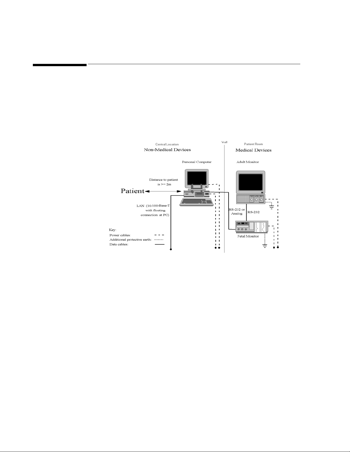
System Overview
System Overview
Centralized System
This configuration shows a typical OB TraceVue system, in which the PC is situated at a
central station and the fetal monitor is at the patient's bedside.
2-2 Safety
Figure 2-1 System Overview, Office (without isolation transformer)
93050913
Page 25
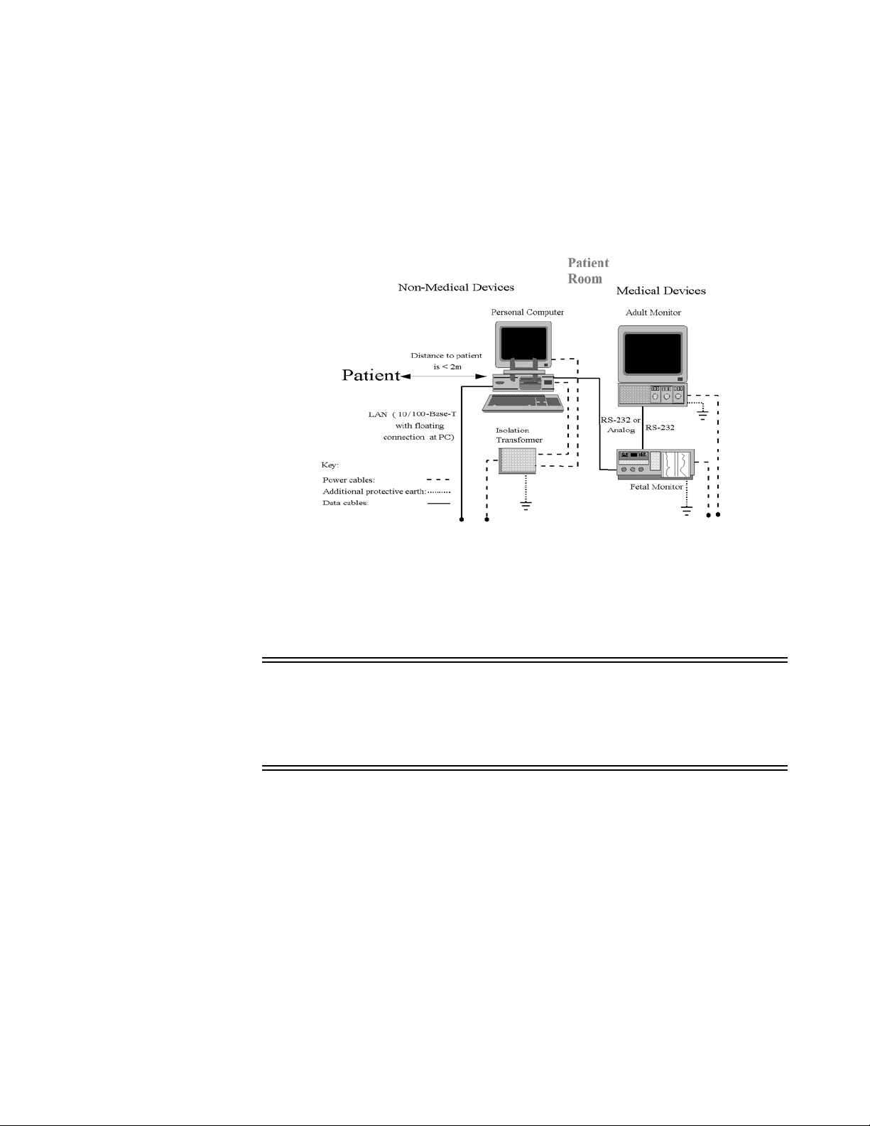
Decentralized System
This configuration shows a typical OB TraceVue system, in which both the fetal monitor
and PC are situated at the patient's bedside.
System Overview
Figure 2-2 System Overview, Bedside (with isolation transformer)
WARNING! Safety regulations require that any PC (both the system unit and display) placed and
operated in the patient vicinity is powered via an approved isolation transformer that
ensures mechanical fixing of the powercords and covering of any unused power outlets.
Do not connect the fetal monitor or an adult monitor to this isolation transformer.
93050913 Safety 2-3
Page 26
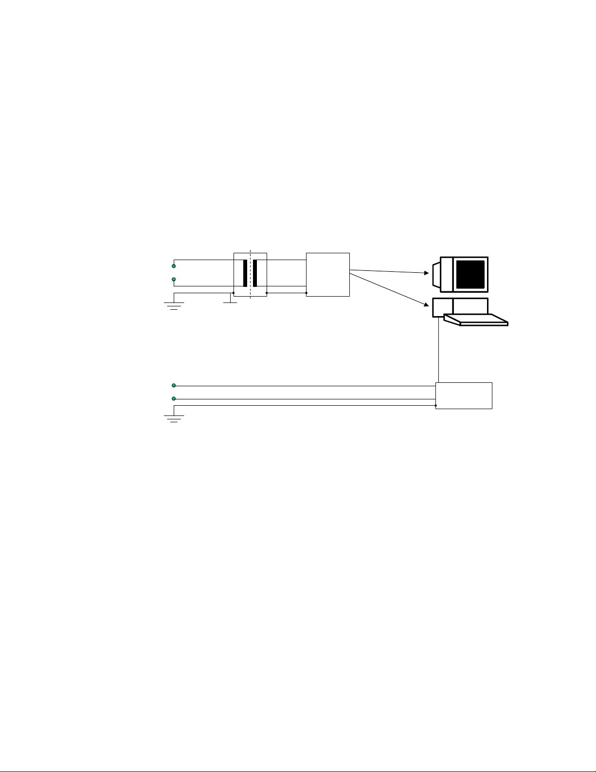
System Overview
Uninterruptible Power Supply (UPS)
An uninterruptible power supply (UPS) will, in the event of a mains power failure, supply
power for a short period of time.
A “server” UPS is supplied with every server PC. This UPS communicates with the server,
so allowing orderly system shutdown.
A “client” UPS is supplied with every client PC, external server and standalone PC. The
hospital’s existing UPS provision is not sufficient.
The configuration in Figure 2-3 shows a typical OB TraceVue system comprising of an
isolation transformer, UPS, PC with display and fetal monitor:
~
~
PC Power Consumption
The current rating information on the PC label (for example, 8.5A for Kayak XA) is not
relevant to OB TraceVue, because it refers to the maximum possible load conditions.
Maximum load conditions would include things such as a high-performance graphics card,
CD-writer, maximum number of processors, maximum system RAM, maximum number of
hard disks, maximum number of cards, and other accessories. This “worst-case” scenario is
not implemented with the OB TraceVue system.
UPS
Medical
Isolation
Transformer
RS232
Fetal Monitor
Figure 2-3 UPS in Patient Vicinity
2-4 Safety
The OB TraceVue maximum power consumption is 300VA at 100-127V as printed on the
isolation transformer (M1389-60001). This transformer controls the total power which is
supplied to the OB TraceVue unit (UPS + PC + display). The maximum current for this unit
is limited to 3.2A by two fuses in the isolation transformer.
93050913
Page 27

Safety Test, Verification, and Customer Acceptance Procedures
Safety Test, Verification, and Customer Acceptance Procedures
This section defines the Test, Verification, and Customer Acceptance procedures applicable
to this product.
Use these tables to determine what test and inspection results must be reported for an
installation or repair, and to determine the format in which these results must be reported
WARNING! Apply the safety test limits set by the local standards and statutes applicable to the
country of installation, such as IEC 601-1, UL2601, CAN/CSA-C22.2 No.601.1.M90
The safety test defined in this chapter is derived from local and international standards
but may not be equivalent. It is NOT a substitute for local safety testing.
Caution: Successful completion of the patient safety tests does not ensure correct and accurate
operation of the equipment.
When performing safety tests, you must use a standard safety tester. You can use testers
complying with IEC 601-1 internationally. You may also use testers complying with any
local standards and statutes applicable to the country of the installation. For safety test
procedures see the operating instructions of the safety tester used.
When running safety tests on the peripheral components of the system, refer to the
documentation included with those products.
Ground leakage current limits apply to the power cables between:
Mains supply
UPS
↔ PC and Display Monitor
Whenever you connect a patient monitor to the OB TraceVue system perform the Test,
Inspection and Safety tests defined for that monitor. Refer to the documentation included
with the patient monitor. If significant parts of the monitor have been exchanged, repaired,
upgraded or worked on in any way you may be required to perform additional tests.
↔ isolation transformer (required if PC & Display in patient vicinity) ↔
93050913 Safety 2-5
Page 28

2-6 Safety
Test and Inspection Matrix
Test and Inspection Matrix
Test Block Name Test or “Inspection” to Perform Expected Test Results
V
isual Inspect all system components for obvious damage.
Are they free of damage?
Expected answers are “yes”.
If so, Visual test is passed.
Is the optical drive environment clean and dust-free?
P
ower On Power on the PC(s) and/or peripheral(s).
Does the self-test complete successfully?
Are user interface controls operational (for example, keyboard, lightpen, mouse,
Expected answers are “yes”.
If so, Power On test is
passed.
display, sound)?
Start OB TraceVue:
- Does the train engine icon animate without flashing?
- Is the OB TraceVue icon bar active and accessible?
P
erformance Perform all individual Performance Tests detailed below.
Do all the individual Performance Tests pass?
Expected answer is “yes”.
If so, Performance Test is
passed.
What to Record on
Service Record
V:P or V:F
where P=Pass and
F=Fail
PO:P or PO:F
where P=Pass and
F=Fail
P:P or P:F
where P=Pass and
F=Fail
93050913
Page 29
93050913 Safety 2-7
Test Block Name Test or “Inspection” to Perform Expected Test Results
Performance
S
oftWare
Step Act io n
1. Start OB TraceVue.
Does the train icon animate without flashing?
Is the correct system date/time displayed? (Year must be 4 digits).
Is the OB TraceVue icon bar active and accessible?
Does the Philips Configuration screen display the correct software
Expected answers are “yes”.
If so, Software test is
passed.
revision?
2.
Server Only (only if storage option exists)
Insert optical media into optical drive / medium changer (initialize if
new).
Optical Drive:
Is the “Disk Status” = “Archive Disk OK” in the Optical Disk
Manager dialog?
Medium Changer:
Is the currently active media listed and is the current archive disk
<servername - date - time> shown at bottom of the Optical Disk
Manager dialog?
3. Admit a test patient, generate/collect some data and then discharge the
test patient with a closed episode.
Can the test patient be retrieved after approximately 10 min?
4. Check print capability from OB TraceVue:
Select the trace, flow chart, note list and current screen check boxes in
the OB TraceVue printing module menu. Print one page for each of
these selections
Can a printout from OB TraceVue be generated?
FORMS PACKAGE Only: Admit a test patient, generate/collect
some data and then discharge the test patient with close episode.
Can the first default Word and Excel document be printed for the test
patient?
What to Record on
Service Record
PSW:P or PSW:F
where P=Pass and
F=Fail
Test and Inspection Matrix
Page 30

2-8 Safety
Test Block Name Test or “Inspection” to Perform Expected Test Results
What to Record on
Service Record
Test and Inspection Matrix
Performance
S
oftWare
(continued)
Step Act ion
5. Check the OB TraceVue to OB TraceVue link.
Admit a test patient, generate/collect some data and then transfer the test
patient to the destination OB TraceVue system.
Is the last episode of the test patient available on the destination
system?
6. Check the ADT link.
Admit a test patient on the central hospital information system.
Is the test patient available on the OB TraceVue system?
7. Check WEB/Terminal Server
At a PC connected to the hospital network:
Start Windows Internet Explorer, connect to the WEB/Terminal Server.
Enter http://<ip address>
Does the OB TraceVue WEB page open?
Does OB TraceVue WEB client start?
1. IP address of WEB/Terminal server external NIC
2. WEB/Terminal server must be registered in the hostname locating service (e.g. DNS) of
hospital network
1
or http://<server name>
2
P
erformance
R
S-232
For each fetal monitor connected to a PC:
At the fetal monitor generate a fetal trace (only one trace at a time).
At the OB TraceVue PC:
Does the trace appear in the single trace display?
Does the data appear in the expected bed?
93050913
Expected answer is “yes”.
If so, RS-232 test is passed.
PRS:P or PRS:F
where P=Pass and
F=Fail
Page 31
93050913 Safety 2-9
Test Block Name Test or “Inspection” to Perform Expected Test Results
Performance Serial
P
ort Server
For each fetal monitor connected to a serial port server:
At the fetal monitor generate a fetal trace (only one trace in the OB TraceVue
system at a time).
Expected answer is “yes”.
If so, serial port server test is
passed.
At the OB TraceVue host PC of the serial port server:
Does the trace appear in the single trace display?
Does the trace appear in the expected bed?
P
erformance UPS Expected answers are “yes”.
Step Acti on
If so, UPS test is passed.
Smart Solution
APC Smart-UPS 1000, see Table UPS Hardware on page 12-18
1. Disconnect power from the UPS while OB TraceVue is running.
Does the PC remain powered?
After 2 minutes, is there a message that indicates that the PC is
running on battery power?
2. Disconnect the serial cable from the UPS while OB TraceVue is
running.
Does the PC display a message indicating that the UPS has a
problem?
Simple Solution
APC Back-UPS / Smart-UPS 620, see Table UPS Hardware on page 12-18
1. Shutdown OB TraceVue and disconnect power from the UPS.
Does the PC remain powered?
2. Wait for 8 Minutes without restoring the power to the UPS.
Is the operating system shut down by the UPS service?
What to Record on
Service Record
PSPS:P or PSPS:F
where P=Pass and
F=Fail
PUPS:P or PUPS:F
where P=Pass and
F=Fail
Test and Inspection Matrix
Page 32

2-10 Safety
Test Block Name Test or “Inspection” to Perform Expected Test Results
Safety PC In Patient vicinity
The PC/display (and client UPS) in the patient vicinity must be connected to a
What to Record on
Service Record
S:P
where P=Pass
Test and Inspection Matrix
Medical Isolation Transformer. The system must be connected as follows:
Mains supply
ity)
↔ UPS ↔ PC & Display Monitor
↔ isolation transformer (required if PC & Display in patient vicin-
Do the isolation transformer and fetal monitor have additional protective earth
connections?
Refer to System Overview on page 2-2.
S
afety (continued) PC Not In Patient vicinity
Does the PC have fetal monitor connections?
Does each fetal monitor have an additional protective earth connection?
Refer to System Overview on page 2-2.
S
afety (1) System Safety Test Enclosure Leakage Current / Normal Condition.
See Enclosure Leakage Current - NC (normal condition) on page 2-12.
System Safety Test Enclosure Leakage Current / Single Fault Condition.
See Enclosure Leakage current - OE (open earth) on page 2-13.
Protective Earth Continuity Test.
See S(1) Protective Earth on page 2-14.
If the answer is “yes”,
Safety test is passed.
If the answer is “no”, perform S
afety(1) test instead.
If the answer is “no”, Safety
test is passed.
If the answer is “yes”, go to
next Step.
If the answer is “yes”,
Safety test is passed.
If the answer is “no”, perform S
afety(1) test instead.
Normal Condition maximum leakage current = x1
(<= 100uA)
Single fault maximum leakage current = x2 (<= 500uA)
With mains cable max.
impedance = x3
(<=200mOhm)
S1:P/x1/x2/x3 or
S1:F/x1/x2/x3
where P=Pass and
F=Fail
93050913
Page 33

93050913 Safety 2-11
Safety Test Procedures
The test procedures outlined in this section is to be used only for verifying safe installation or service of the product.
The setups used for these tests and the acceptable ranges of values are derived from local and international standards but may not be
equivalent.
This test is not a substitute for local safety testing
where it is required for an installation or a service event.
If using the Metron Safety tester use your local regulation to perform the test, for example in Europe IEC601-1/IEC601-1-1 and in
the US UL2601-1. The Metron Report should print results with the names listed below, along with other data.
“Safety checks at installation refer to safety aspects directly related to the installation and setup activities and not to intrinsic safety
features that have already been checked during final acceptance testing at the factory”
[FDA 97-4179 Medical Device Quality Systems Manual: A Small Entity Compliance Guide (QSR Manual) First Edition December
1996. Chapter 14: Storage, Distribution and Installation. This document may be viewed at http://www.fda.gov]
Test and Inspection Matrix
Page 34

2-12 Safety
Test and Inspection Matrix
Test Block Name Test or Inspection to perform
S(1) System
Enclosure Leakage Current - NC
(normal condition)
Instrument under test
L (N)
Medical electrical system
Signal parts
in- and/or
output
Signal parts
(**)
in- and/or
output
Other
Instrument
N (L)
S2
S1
S4
(*)
MD
PE
(*) Not present in Class 2.
(**) Can be multiple different connections to different equipment at same time.
Applied part
Measures leakage current of exposed metal parts of Instrument under Test (IUT) and between parts of the system
within the patient vicinity; normal and reversed polarity using S2.
Use CATI-program with all components connected (PC display - transformer system must be tested, the RS-232 and
LAN connection must be made).
Apply test to point of patient contact: fetal monitor. The system test detects leakage problems caused by any component.
Run the test on each fetal monitor. If more than one fetal monitor is connected to the same PC or serial port server,
disconnect the power cables of the fetal monitors not being tested.
In the patient vicinity: Run the test on each PC system (includes PC, display, UPS, transformer). The whole system
is tested together.
Outside patient vicinity: No component tests.
Safety test according IEC 601-1-1 (Clause 19.201.1) Report largest value
93050913
Page 35

93050913 Safety 2-13
Test Block Name Test or Inspection to perform
S(1) System
Enclosure Leakage current - OE
(open earth)
L (N)
Instrument under test
Medical electrical system
Signal parts
in- and/or
output
Signal parts
(**)
in- and/or
output
Other
Instrument
N (L)
S2
S1
S4
MD
PE
(**) Can be multiple different connections to different equipment at same time.
Applied part
Measures leakage current of exposed metal parts of Instrument under Test (IUT) with Protective Earth (PE) open circuit (S4=open) and between parts of the system within the patient vicinity; normal and reversed polarity using S2.
Use CATI-program with all components connected (PC display - transformer system must be tested, the RS-232 and
LAN connection must be made).
Apply test to point of patient contact: fetal monitor. The system test detects leakage problems caused by any component.
Run the test on each fetal monitor. If more than one fetal monitor is connected to the same PC or serial port server,
disconnect the power cables of the fetal monitors not being tested.
In the patient vicinity: Run the test on each PC system (includes PC, display, UPS, transformer). The whole system
is tested together.
Outside patient vicinity: No component tests.
Safety test according IEC 601-1-1 (clause based on 19.201.1} Report largest value.
Test and Inspection Matrix
Page 36

2-14 Safety
Test and Inspection Matrix
Test Block Name Test or Inspection to perform
S(1) Protective Earth
Instrument under test
L (N)
PE
N (L)
Applied part
(*)
Insulating pad
(*) If equipotential connection present : measure also
with yellow/green E.P. conductor connected.
Ri
Ohm
6V
50 Hz 25 A or 1.5 Ir
Assures impedance of Protective Earth (PE) terminal to all exposed metal parts of Instrument under Test (IUT), which
are connected to the Protective Earth (PE) for safety reasons. Normally it includes the wiring in the mains cable (max.
200mOhm). A test current of 25 Amps applied for 5 to 10 seconds. It is recommended to flex the main cable during
the test to identify potential bad contact or damage to the earth wire. Safety test according to IEC 601-1 (Clause 18).
Report the greatest value.
93050913
Page 37

93050913 Safety 2-15
When to Perform Test Blocks
Service Event
When performing.....
Test Block(s) Required
Complete these tests
Installation Visual, Power On, Performance, Safety, Safety(1) if required.
Preventive Maintenance Customer responsibility
Repair - PC (display, internal PC components) Power On, Performance Software, Safety, Safety(1) if required.
If replacing RS-232 card, also do Performance RS-232 test.
Repair - peripherals (printer, optical drive / medium
changer)
Power On, Performance SoftWare
For printer, only do Performance SoftWare (step 4).
For optical drive, only do Steps 1-3 of Performance SoftWare.
Repair - software reload (Operating system, OB TraceVue) Power On, Performance
Repair - RS-232 (cables, converters) Performance RS-232
Repair - Serial Port Server Performance Serial Port Server
Repair - hub/LAN Power On
Repair - UPS Visual, Performance UPS, Safety, Safety(1) if required.
Repair - isolation transformer Visual, Performance UPS, Safety, Safety(1) if required.
Upgrade - add sound, lightpen, display, memory,
Power On, Performance, Safety, Safety(1) if required.
2nd network card
Upgrade - add JetDirect card Power On, Performance SoftWare (step 4).
Upgrade - add optical (MO) drive Power On, Performance SoftWare (steps 1-3).
Upgrade - add optical medium changer Power On, Performance SoftWare (steps 1-3).
Upgrade - add RS-232 card Power On, Performance RS-232, Safety, Safety(1) if required.
Upgrade - add serial port server Power On, Performance Serial Port Server
All other Service Events Visual, Power On, Performance, Safety, Safety(1) if required.
Test and Inspection Matrix
Page 38

Safety and Site Preparation
Safety and Site Preparation
After running the tests, return the system to its pre-test condition to restore safe operating
conditions.
WARNING! 1. Site Preparation may involve the application of Mains/Line voltage to the test
lead.
USE EXTREME CAUTION TO AVOID SEVERE PERSONAL INJURY OR
DEATH.
2. To ensure test accuracy, equipment must be isolated electrically from ground.
Safety Notes for Cabling and Installation
Fetal Monitor
The thick yellow-black ground cable is NOT required. It cannot be used as a required
safety connection, as it can be removed without tools. It is, however, an additional
safety feature.
All metal parts in the patient room must be grounded to protective earth.
PC in Patient Vicinity
To meet the requirements of IEC 601-1-1 when a PC is located in the patient vicinity:
Use an isolation transformer to supply both the display and the system unit of the PC.
The devices must be connected in the following order:
Mains supply
DO NOT connect the PC to any other device, such as a printer, or a modem, unless the
device has an isolation transformer or a floating power supply.
See the Site Preparation Guide for full cabling details.
Network Verification
↔ isolation transformer ↔ UPS ↔ PC & Display Monitor
2-16 Safety
Network verification is required. This is part of the wall cabling installation, and is NOT
bundled with OB TraceVue. It is the customer’s responsibility to obtain network
certification.
93050913
Page 39

Electrostatic Handling Precautions
Static electricity can damage electronic components. To prevent damage, observe the
following handling precautions:
Use a grounding wrist strap, if available, connected to the metal frame of the computer.
To dissipate static electricity, the power cord must be connected between the PC and
the wall outlet (by way of the isolation transformer) with the system switched off. If
there is no isolation transformer, you require a grounded work place.
Always touch the metal part of the computer frame just before handling a circuit board
or disk drive.
Avoid directly touching components or edge connectors on the board. Handle circuit
boards and disk drives by their metal brackets or frames.
Emissions and Immunity
Electrostatic Handling Precautions
The product is designed and evaluated to comply with the emissions and immunity
requirements of international and national EMC standards. See the following tables for
detailed information regarding declaration and guidance.
The EMC standards state that manufacturers of patient-coupled equipment must specify
immunity levels for their systems. See Table Electromagnetic Immunity - General on page
2-19 and Table Electromagnetic Immunity on page 2-20 for this detailed immunity
information. See Table Recommended Separation Distances on page 2-21 for
recommended minimum separation distances between portable and mobile communications
equipment and the product.
Immunity is defined in the standard as the ability of a system to perform without degradation
in the presence of an electromagnetic disturbance. Degradation in system performance is a
qualitative assessment which can be subjective.
Caution should, therefore, be taken in comparing immunity levels of different devices. The
criteria used for degradation is not specified by the standard and can vary with the
manufacturer.
Guidance and Manufacturer’s Declaration
The product is intended for use in the electromagnetic environment specified in the
following tables. The customer or the user of the product should assure that it is used in such
an environment.
93050913 Safety 2-17
Page 40

Emissions and Immunity
Table 2-1 Electromagnetic Emissions
Emissions Test Compliance Electromagnetic Environment Guidance
Radio Frequency
(RF) emissions
CISPR 11
or
CISPR 22
RF emissions
CISPR 11
or CISPR 22
Harmonic emissions
IEC 61000-3-2
Voltage fluctuations/flicker emissions
IEC 61000-3-3
Group 1
Class A
Class A
Complies
The
product uses RF energy only for its internal
function. Therefore, its RF emissions are very low
and not likely to cause interference in nearby electronic equipment.
The
product is suitable for use in all establish-
ments, other than domestic and those directly connected to the public low-voltage power supply
network that supplies buildings used for domestic
purposes.
2-18 Safety
93050913
Page 41

Table 2-2 Electromagnetic Immunity - General
Emissions and Immunity
Immunity Test
Electrostatic discharge (ESD)
IEC 60601
Test Level
+
6 kV contact
+
8 kV air
Compliance
Level
6 kV contact
+
+
8 kV air
IEC 61000-4-2
Electrical fast transient/burst
IEC 61000-4-4
Surge
IEC 61000-4-5
Voltage dips, short
interruptions, and
voltage variations
on power supply
input lines
IEC 61000-4-11
Power frequency
+
2 kV for power
supply lines
+
1 kV for input/out-
put lines
+
1 kV differential
mode
+
2 kV common
mode
< 5% U
a
T
(> 95% dip in UT)
for 0,5 cycle
40% U
T
(60% dip in UT)
for 5 cycles
70% U
T
(30% dip in UT)
for 25 cycles
< 5% U
T
(> 95% dip in UT)
for 5 sec
3 A/m 3 A/m Power frequency magnetic fields should be at levels char-
+
2 kV for power
supply lines
+
1 kV for input/
output lines
+
1 kV differential
mode
+
2 kV common
mode
< 5% U
(> 95% dip in UT)
for 0,5 cycle
40% U
(60% dip in UT)
for 5 cycles
70% U
(30% dip in UT)
for 25 cycles
< 5% U
(> 95% dip in UT)
for 5 sec
a
T
T
T
T
(50/60 Hz)
magnetic field
IEC 61000-4-8
a
UT is the AC mains voltage prior to application of the test level.
Electromagnetic Environment - Guidance
Floors should be wood, concrete, or ceramic tile. If floors
are covered with synthetic material, the relative humidity
should be at least 30%.
Mains power quality should be that of a typical commercial or hospital environment.
Mains power quality should be that of a typical commercial or hospital environment.
Mains power quality should be that of a typical commercial or hospital environment. If the user of the product
requires continued operation during power mains interruptions, it is recommended that the product be powered from
an uninterruptible power supply or a battery.
acteristic of a typical location in a typical commercial or
hospital environment.
93050913 Safety 2-19
Page 42
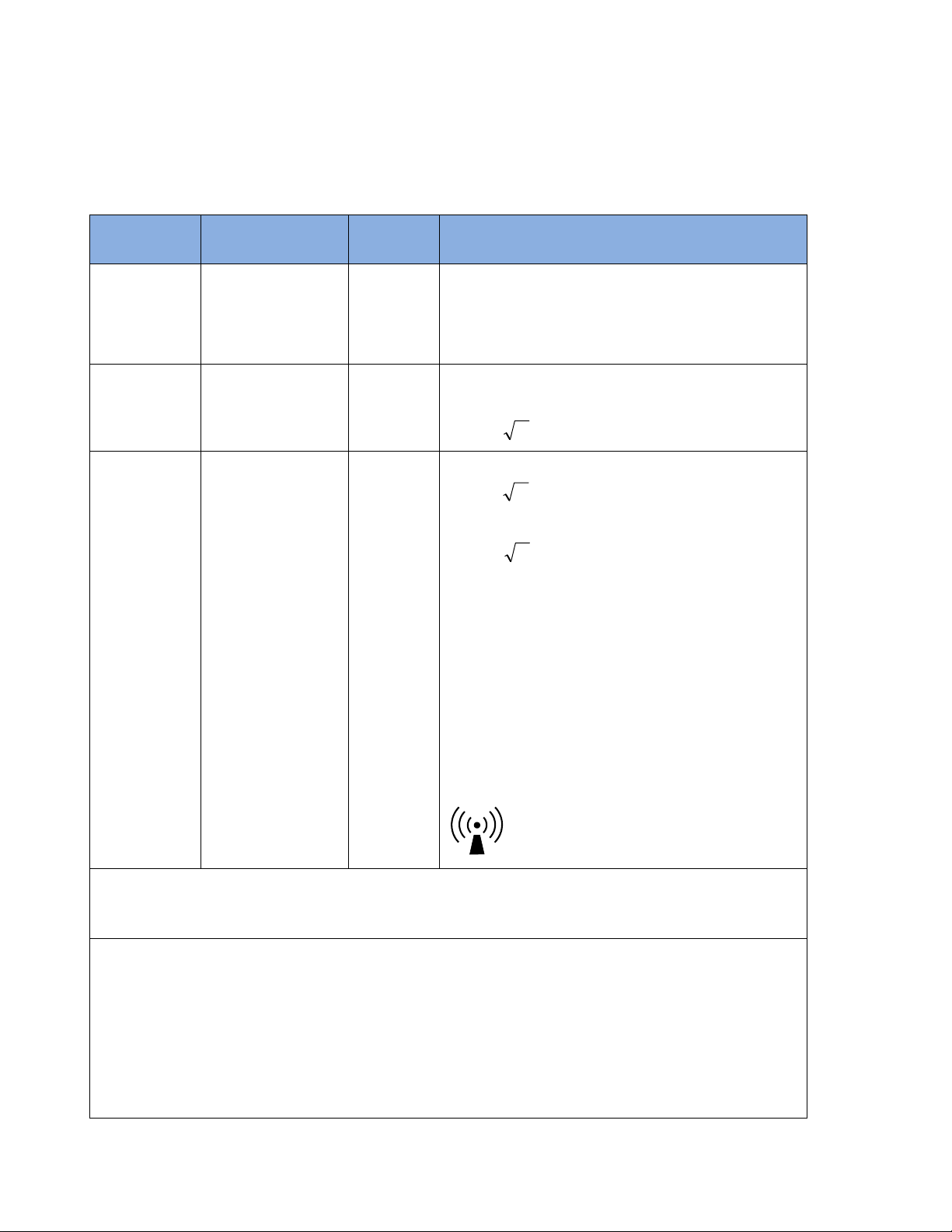
Emissions and Immunity
Table 2-3 Electromagnetic Immunity
Immunity Test
Conducted RF
IEC 61000-4-6
Radiated RF
IEC 61000-4-3
IEC 60601
Test Level
3 Vrms
150 kHz to 80 MHz
3 V/m
80 MHz to 800 MHz
80 MHz to 2.5 GHz
Compliance
Level
3 Vrms
3 V/m
Electromagnetic Environment - Guidance
Portable and mobile RF communications equipment
should be used no closer to any part of the product,
including cables, than the recommended separation distance calculated from the equation applicable to the frequency of the transmitter.
Recommended Separation Distance
Pd 2.1=
Pd 2.1=
Pd 3.2=
where P is the maximum output power rating of the transmitter in watts (W) according to the transmitter’s specified output power and d is the recommended separation
distance in meters (m).
Field strengths from fixed RF transmitters, as determined
by an electromagnetic site survey,
compliance level in each frequency range.
Interference may occur in the vicinity of equipment
marked with the following symbol:
a
should be less than the
b
At 80 MHz and 800 MHz, the higher frequency range applies.
These guidelines might not apply in all situations. Electromagnetic propagation is affected by absorption and
reflection from structures, objects and people.
a
Field strengths from fixed transmitters, such as base stations for radio (cellular/cordless) telephones and land
mobile radios, amateur radio, AM and FM radio broadcast and TV broadcast cannot be predicted theoretically
with accuracy. To assess the electromagnetic environment due to fixed RF transmitters, an electromagnetic site
survey should be considered. If the measured field strength in the location in which the product is used exceeds the
applicable RF compliance level above, the product should be observed to verify normal operation. If abnormal
performance is observed, additional measures are necessary, such as re-orienting or relocating the product.
b
Over the frequency range 150 kHz to 80 MHz, field strengths should be less than 3 V/m.
2-20 Safety
93050913
Page 43

Emissions and Immunity
Recommended Separation Distances
The product is intended for use in an electromagnetic environment in which radiated RF
disturbances are controlled. The customer or the user of the product can help prevent
electromagnetic interference by maintaining a minimum distance between portable and
mobile RF communications equipment (transmitters) and the product as recommended
below, according to the maximum output power of the communications equipment.
Table 2-4 Recommended Separation Distances
Separation Distance According to Frequency of Transmitter (m)
Rated Maximum Output
Power of Transmitter (W)
0.01 0.1 m 0.2 m
0.1 0.4 m 0.7 m
1 1.2 m 2.3 m
10 4 m 7 m
100 12 m 23 m
For transmitters rated at a maximum output power not listed above, the recommended separation distance d in meters (m)
can be determined using the equation applicable to the frequency of the transmitter, where P is the maximum output power
rating of the transmitter in watts (W) according to the transmitter’s manufacturer.
At 80 MHz and 800 MHz, the higher frequency range applies.
These guidelines might not apply in all situations. Electromagnetic propagation is affected by absorption and reflection
from structures, objects and people.
150 kHZ to 800 MHz 800 MHz to 2.5 GHz
Pd 2.1=
Pd 3.2=
93050913 Safety 2-21
Page 44

Emissions and Immunity
2-22 Safety
93050913
Page 45

Introduction
3
Security
OB TraceVue
Security
Operating System
Security
General Security
Rules
The OB TraceVue configuration and the patient data stored by OB TraceVue are protected
by assigning the required user rights such as System Manager and Super User permission and
access rights such as Read or Write permissions.
For details refer to the Instructions for Use.
To protect the OB TraceVue data files against modification, to ensure patient data safety,
and to protect the OB TraceVue installation as well as the operating system against
corruption only administrators have full access to OB TraceVue computers.
Although standard Windows users have only limited access to the computer they can fully
operate OB TraceVue including all system management tasks if they have the
corresponding OB TraceVue user rights.
Do not assign administrator rights to the windows user group users or OBTV users.
The standard Windows user log on should be member of the user group users and
OBTV users.
Windows administrator accounts should only be used for administration purposes.
Change administrator passwords on a regular basis.
Do not change access rights of directories or shares.
93050913 Security 3-1
Page 46

Windows Security
Windows Security
Windows User Groups
OBTV Internal Created by the OB TraceVue setup.
Do not add users to this group; do not change any setting of this group.
OBTV Users
Administrators
Users
Windows Users
OBTV Internal
OBTV Connect
OBTV
Administrator
Administrator
Created by the OB TraceVue setup.
Users who are not members of Administrators must be member of this group in order
to start OB TraceVue.
Do not change any setting of this group.
Predefined by Windows.
Members have full access to the computer.
Predefined by Windows.
Members have limited access to the computer.
For internal use by OB TraceVue only.
It is not possible to log onto Windows using this account.
Do not change any setting of these users.
For administration purposes, member of Administrators.
Full access to the computer.
It is recommended to change the password after OB TraceVue installation.
Predefined by Windows, member of Administrators.
Full access to the computer.
It is recommended to change the password after OB TraceVue installation.
3-2 Security
User
Default user account for running OB TraceVue, member of users and OBTV users.
Limited access to the computer.
It is not possible to run applications that require administrator rights using this user
account.
Table 3-1 Windows Users and Groups
User Group
User
OBTV Internal Administrators Users OBTV Users
OBTV Internal OBTV Connect OBTV Administrator User Administrator
93050913
Page 47

Access Rights
Windows Security
Data on the hard disk of OB TraceVue PCs is protected by Windows access rights:
Members of the groups Administrators and OBTV Internal have full access to the OB
TraceVue directories, shares, and registry settings.
All other users have limited access:
Directories
Table 3-2 Directory Access Rights
Directory Access Rights
C:\TV2 Read & Execute
C:\TV2\cfg_exp Read & Execute
C:\TV2\db No Access
C:\TV2\dbbackup No Access
C:\TV2\extdb
1
No Access
C:\TV2\hl7 Read & Execute
C:\TV2\logdata Full Control
C:\TV2\patdata Read & Execute
C:\TV2\prog Read & Execute
C:\TV2\setup Read & Execute
C:\TV2\sounds Read & Execute
C:\TV2\sqlany Read & Execute
C:\TV2\tools Read & Execute
2
D:\TV2
No Access
D:\TV2\db No Access
D:\TV2\dbbackup No Access
1. External Server PC only
2. Archive systems only (no RAID)
(of users not member of Administrators)
93050913 Security 3-3
Page 48

Windows Security
Shares
Table 3-3 Share Access Rights
Directory on
standard
Share
installation,
with backup
drive D
(of users not member of Administrators) and on which PC type they reside
Directory on
standard
installation,
without backup
drive D
Server C:\ C:\
OBTraceVue C:\TV2 C:\TV2
OBTVTemplates C:\TV2_Templates C:\TV2_Templates
OBTVReplication$ D:\TV2\db C:\TV2\db
SYSROOT$
C:\ C:\
Access Rights PC Type
Read Internal Server
Read Internal Server
Read Internal Server
Read Internal Server
Read All
3-4 Security
93050913
Page 49

Windows Security
Tools The table below lists the Windows and OB TraceVue access rights required to start a tool.
Table 3-4 Tools Access Rights
To ol
Administration Tool
Check Upgrade
Configuration Backup Tool
Database Rebuild Tool
External Database
Administration Tool
Fetal Monitor Spy
Get Log
Link Recovery Tool
Local Data Recovery Tool
Logfile Viewer
Offline Backup Tool
OB TraceVue Setup
Optical Disk Test Tool
Patient Search Tool
Retrieve from Optical
Shell
System Overview Tool
Update Document
Templates
Value Table Editor
1. If checked, Windows administrator rights are required to start the tool. See Log On As Windows
Administrator on page 3-6.
2. Tools that require OB TraceVue permission rights display a login dialog. Only OB TraceVue users
with all listed rights can log in (Link Recovery and Value Table Editor: SM or SU).
3. System Manager permission rights.
4. Super User permission rights.
5. Permission to view patient data.
6. Permission to change patient data
Admin
-
-
-
-
-
-
-
-
-
-
-
OB TraceVue
1
3
SM
Rights
4
SU
2
5
R
W
⌧⌧⌧
⌧
⌧
⌧
⌧⌧⌧
⌧
⌧
Remarks
6
Special db user (TVA) and password
required. See Integration Guide.
Special setup passwords required.
Special password required.
See page 15-23.
Windows administrator rights required
to save the configuration.
Offline mode: special password.
93050913 Security 3-5
Page 50

Windows Security
Interrupting Auto Login
If Windows Auto Login (see Auto Login on page 16-8) is configured you need to interrupt
that in order to login as a different Windows user.
Hold down the Shift key while Windows is booting.
Log On As Windows Administrator
If administrator rights are required (for example, to start a tool or to install drivers):
1. Shut down OB TraceVue.
2. Log off Windows.
3. Log on Windows as a user who is member of the Windows Adminstrators user group
(for example, OBTV Administrator or Administrator).
4. Start the tool.
5. When finished, log off, log on as user.
6. Start OB TraceVue.
Modifying Access Rights
For some tasks (for example installation of Word/Excel service releases) it is not sufficient
to log on as an administrator. Instead, the user user requires administrator rights:
After having finished driver installation remove the user user from the Administrators group
to restore security.
Adding User to
Administrators
Group
Removing User
Administrators
Group
1. Log on as Windows administrator.
2. Start Computer Management
3. Double-click user.
4. Click the Member Of tab, click Add ...
5. Select Administrators, click Add.
6. Click OK.
1. Start Computer Management
from
2. Double-click user.
3. Click the Member Of tab
4. Select Administrators, click Remove.
5. Click OK.
→ Local Users and Groups, select Users.
→ Local Users and Groups, select Users.
3-6 Security
93050913
Page 51

Overview
4
System Description
OB TraceVue is a PC-based network system for obstetrical surveillance, alerting, and
patient data management that supports a server and a maximum of 100 client PCs and 50
fetal monitors per network.
Key options include patient data storage to optical disk; an external server used, for
example, to facilitate forms based patient records and statistical reporting; an optional
Admission Discharge Transfer (ADT) link to the Hospital Information System (HIS); and an
optional WEB access.
Operating system: Microsoft Windows 2000 Server for a standalone PC, internal
server, and (optional) external database server PC; Microsoft Windows 2000
Professional at client PCs.
Relational Database: Sybase Adaptive Server Anywhere 8
Optional forms based patient documentation and statistical reporting using Microsoft
Word and Excel templates.
Network: Microsoft Windows 2000, client-server structure, with star topology,
Ethertwist 10/100baseT cabling.
Network Protocol: TCP/IP
An optional 2
to an isolated external TCP/IP network.
Connection via routing ports over the hospital backbone is also possible.
The cable between a fetal monitor and PC uses DB-9 connectors. Where necessary for
the fetal monitor, an RS-232 protocol converter is used.
nd
network interface card allows the OB TraceVue LAN to be connected
93050913 System Description 4-1
Page 52

Centralized Implementation
Centralized Implementation
A centralized implementation includes:
An internal server.
Client PCs at Central Station, used for data acquisition.
An optional serial port server used to connect up to 16 fetal monitors.
An optional external server, never used for data acquisition.
Fetal monitors in patient rooms, connected to wallplates.
A switch, for PC to PC and other network connections, perhaps located at the Central
Station.
Wall cabling: Serial (RS-232) connection between client PCs and fetal monitors:
Cable-type: Ethertwist UTP.
Connectors: 9 pin DSUB.
Installation: M1380D, option K41 Serial wall-cable kit (kit for six Fetal Monitors).
Decentralized Implementation
A decentralized implementation includes:
An internal server in a secure location.
Client PCs at Central Station, not used for data acquisition.
An optional External server, never used for data acquisition.
An optional WEB/Terminal server, never used for data acquisition.
Client PCs in patient rooms next to fetal monitors allowing bedside data entry
(Isolation transformer required in patient vicinity).
Fetal monitors in patient rooms connected directly to client PC.
One or more switches, for PC to PC and other network connections, typically located
in cable room(s).
Wall cabling: LAN-connection between server, clients and switch.
4-2 System Description
Cable-type: Ethertwist UTP.
Connectors: RJ45.
Installation: M1380D, opt K42 LAN wall-cable kit (kit for 6 PCs).
93050913
Page 53

Shipment Status
If the PC is an internal server or external server or standalone, the Microsoft Windows 2000
Server is pre-installed. If the PC is a client, Microsoft Windows 2000 Professional is preinstalled.
If the optional external server is ordered with the optional forms based patient record
licence, Microsoft Word and Excel are pre-installed.
All the internal hardware components ordered for a PC are fitted by the factory. For
example: a lightpen card, serial interface card, or the SCSI host adapter and additional hard
disk required for an internal server with archiving.
Any software, such as additional drivers, required for the internal components fitted to a PC
is pre-installed. Any settings required (such as IRQ allocation, address or DMA settings) are
made by the factory.
An external component, such an optical drive, may require some setup.
For PCs supplied for new systems, the appropriate OB TraceVue software is pre-installed.
Shipment Status
For upgrade PCs, the appropriate OB TraceVue application software must be installed onsite.
The printer driver is not installed. You may need to amend the PC BIOS to enable its parallel
port, and install a printer driver. You may need to connect PCs to a printer that is shared with
other PCs in the LAN, or to a printer that has been connected to the LAN using a JetDirect
card.
93050913 System Description 4-3
Page 54

Hardware
Hardware
PCs/Memory
This section describes the PCs shipped with OB TraceVue systems, so are representative of
the hardware required. The exact model and type of hardware used will change, with newer
models substituted as they become available.
Note The hardware supplied for earlier versions of OB TraceVue systems may not meet these
nominal specifications. Refer to Chapter 18, Upgrade Overview for details of how these PCs
can be upgraded, and what restrictions apply to their use in an OB TraceVue system.
Table 4-1 PCs / Memory
Memory (MB)
PC Hardware
Server
HP Compaq dc7600 512 1024 2048 512
HP Compaq dc7600
with serial port server
HP ProLiant ML350 G4p 2048 2048 4096 -
512 - - 512
External
Server
WEB/
Terminal
Server
Client
4-4 System Description
93050913
Page 55

Optical Disk Drives and Medium Changers
All OB TraceVue servers with storage can use the following optical disk drives:
5200ex 5.2GB (C1114J)
9100mx 9.1GB (C1114M)
220mx 9.1GB Medium Changer (C1119M)
Hardware
Drive Combinations
Cabling
Displays
Table 4-2 Supported Optical Disk Drive Combinations
Archive Drive (GB) Retrieve Drive (GB) Supported Media (GB)
5.2 5.2 5.2
5.2 9.1 5.2
9.1 5.2 5.2
9.1 9.1 9.1 / 8.6 / 5.2
Table 4-3 Connecting Optical Drives
PC ↔ First Drive
M1383-61601 (1m)
(+M1381-61608)
M1381-13750 (1.5m)
(+M1381-61608)
1. Additionally required for ML370 high-end server PCs.
1
1
First Drive (GB)
9.1 or 5.2 8120-5548CP
optical media
changer (jukebox)
First Drive ↔ Second
Drive
(HP C2908A)
M1383-61601
Second Drive (GB)
9.1 or 5.2
OB TraceVue is optimized to a display resolution of 1024 x 768 pixels, minimum 256
colors.
The current version of OB TraceVue can be displayed at different resolutions, but
readability may suffer.
93050913 System Description 4-5
Page 56

Software Components
Software Components
OB TraceVue
OB TraceVue is supplied with:
a bootable CD-ROM for Server PC, including:
Microsoft Windows 2000 Server
OB TraceVue software for internal server and standalone PCs; external server
PCs
BIOS images for every type of PC supplied for OB TraceVue
A disk image of the Boot floppy disk
This floppy disk is suitable for every type of PC supplied for OB TraceVue,
whether used as an OB TraceVue internal server/standalone, client, or external
server.
a bootable CD-ROM for client PCs, including:
Third Party Software
Some application software used with OB TraceVue is from third parties. For example,
Microsoft Word and Excel are used by optional Forms based patient record and statistical
reporting packages.
Caution: Do not install third party application software at the internal server PC and at the
WEB/Terminal server PC.
Do not install or update third party application software unless either:
Sanctioned by a Service Note.
Tested prior to use in accordance with the instructions specified in the Integration
Microsoft Windows 2000 Professional
OB TraceVue software for client PCs
BIOS images for every type of PC supplied for OB TraceVue
A disk image of the Boot floppy disk
This floppy disk is suitable for every type of PC supplied for OB TraceVue,
whether used as an OB TraceVue internal server/standalone, client, or external
server.
Guide.
4-6 System Description
93050913
Page 57

Wall Cabling and Faceplates
Refer to the Site Preparation Guide for this information.
Wall Cabling and Faceplates
93050913 System Description 4-7
Page 58

System Limitations
System Limitations
OB TraceVue has certain implementation restrictions:
Power
An isolation transformer is required for any PC operated in the patient vicinity, even
when a UPS is used. The isolation transformer must be connected in the following
order:
Mains supply
Hubs, switches and serial port servers must have a stable power supply. If possible
connect to UPS.
PCs and Fetal Monitors
1
↔ isolation transformer ↔ UPS ↔ PC & Display Monitor
Each PC supports a maximum of four local RS-232 serial ports
A small surveillance system (internal server, no forms based patient record and no
2
.
more than three clients) may have up to three fetal monitors connected to the internal
server, one COM port being used by the server UPS.
If all four COM ports are used to connect fetal monitors the server UPS must be used
off-line. In the event of a power outage the server must be shut down manually.
If more than 20 clients are connected to the server, no fetal monitors may be connected
to the internal server.
A maximum of 16 fetal monitors (FMs) may be connected directly to one PC.
A maximum of 100 clients may be online at any one time with the high end internal
server. See also Table 18-2, Server Memory, Clients, Fetal Monitors, on page 18-4.
We do not recommend using the HP Netserver LC2000, Compaq ProLiant ML 370, or
ML 350 PC as a workstation; it is intended as a server PC and must be installed in a
secure area.
4-8 System Description
1. These restrictions apply to a new OB TraceVue D.01.13 system. Other restrictions
may apply to hardware supplied for earlier an OB TraceVue versions and that has
been upgraded to OB TraceVue D.01.13
2. An optional additional RS-232 PCI serial interface card is used to provide COM3 and
COM4
93050913
Page 59
Serial Port Servers
Modems
System Limitations
Serial port servers must not be installed in the patient vicinity.
Serial port servers can be hosted at
Standalone PCs
Internal Server PCs
Client PCs
A maximum of 16 serial ports can be hosted on one PC. Fetal monitors connected
directly to a PC count as one port.
Up to 8 serial port server devices may be hosted on a single PC.
Up to 30 serial port servers may be operated in one OB TraceVue system.
Do not connect a modem to a PC placed and operated in the patient vicinity.
Table 4-4 Maximum Number of Modems per OB TraceVue System
PC Type Modems
Remote Trace Transmission 6
WEB Access
Remote Support 2
Fax
Table 4-5 Maximum Number of Modems per OB TraceVue PC
PC Type
Internal Server
Internal Server
External Server -- 1
WEB/Terminal Server -3
Client
with Data Acquisition 4 ---
Client
without Data Acquisition ---1
1. The number of modems connected directly to a PC cannot exceed the number of available RS-232
interfaces. If RS-232 interfaces are used for other purposes (e.g. UPS, Fetal Monitor connection) the
number of modems that can be connected is reduced accordingly.
2. One modem; shared by remote support and fax. Cannot be used for both purposes as the same time.
3. Two RS-232 plus one USB.
(more than 20 clients)
(less than 21 clients)
not limited, but maximum number of clients must not be exceeded
not limited
1
Remote Trace
Transmission
supported modem only
WEB
Access
standard modem 28 KBps or faster
Remote
Support
Fax
--1-
4- 1
3
2
2
-1
93050913 System Description 4-9
Page 60

System Limitations
Interfacing
Network
OBMS Retrieval
Only one additional network interface card per PC is allowed in the system.
The optional ADT link can be installed on a client PC not used for data acquisition.
Database export to the hospital network (optional) requires the optional external
database server.
The high-end internal server allows a maximum 100 client PCs to be online at any one
time. See also Table 18-2, Server Memory, Clients, Fetal Monitors, on page 18-4.
A client PC used to facilitate the optional ADT interface counts as a client connection.
The optional External server and each WEB/Terminal client session count as a client
connection to the internal server.
For more information, refer to the OBMS Copy and Retrieve Guide pn M1381-9140K or
newer.
4-10 System Description
93050913
Page 61

Documentation
Documentation
This documentation and software described here originates from Philips and third party
suppliers.
This section describes the documentation that is supplied with the OB TraceVue hardware,
depending on the options ordered. Documentation is available on the documentation CDROM for other manuals not mentioned in this list. The HP PC’s Service Manual, and
Windows manuals are not supplied.
OB TraceVue:
Instructions for Use
System Administration and Configuration Guide
Integration Guide
Site Preparation Guide
Installation and Service Manual
Other Documentation:
Microsoft Windows Server documentation.
(On CD-ROM - Paper documentation is not supplied)
PC documentation CD ROM
Any documentation supplied with PCI network card
Any documentation supplied with RS-232 serial interface card
SCSI host adapter documentation
HP Optical Disk Drive documentation
HP Optical Jukebox Model 125ex/220mx Service Manual
Display User's Guide
HP Switch Installation and Reference Guide
APC Back-UPS User’s Manual (with optional client UPS)
HP documentation supplied with printer.
Moxa NPort Server User’s Manual
93050913 System Description 4-11
Page 62

Documentation
4-12 System Description
93050913
Page 63

Introduction
PC Types
Introduction
5
New System Setup
This chapter tells you how to get a new system up and running. Most hardware and software
is pre-installed at the factory but you have to connect and configure the system.
You should also check the Technical Marketing Softserver for the latest OB TraceVue
service pack and ensure that it is installed.
There are different types of OB TraceVue PCs:
Internal Server PC (includes server without client PCs; formerly: Standalone)
External Server PC
WEB/Terminal Server PC
Client PCs used for data acquisition from fetal monitors (Client Data Acq.)
Client PCs not used for data acquisition (Other Client)
This chapter consists of a sequence of tasks you must do to install all types of PCs. Each
tasks starts with a small table indicating for which PC type(s) the task is relevant. To install
an OB TraceVue PC, start with task number 1 and go through the tasks that are marked for
your PC type.
X Internal Server
External Server
WEB/Terminal Server
Client Data Acq.
Other Client
A description of how to start WEB clients and install real-time WEB clients can be found at
the end of this chapter.
Order in which to Perform Tasks
The order in which you perform the tasks is important. When installing a system (server and
at least one client), please observe the following workflow:
1. Install the internal server.
2. Install each client.
93050913 New System Setup 5-1
Page 64

Installation Checklists
Installation Checklists
The following pages are installation checklists, one for each PC type. To use the installation
checklists:
For each PC in your installation:
1. Determine the type of PC (server, standalone, external server, WEB/Terminal server,
client with data acquisition, or other client). Make a copy of the appropriate installation
checklist.
2. Install the PC by performing the tasks in the checklist. If a check box is enclosed in
parentheses, the task is optional or conditional.
For each task, the task number refers to the tasks as described in this chapter. The page
number(s) refer(s) to the page(s) where information on how to perform the task can be
found. Page numbers in bold type refer to the pages with the greatest level of detail.
3. After completing a task, check the check box in the checklist.
When you have finished installing all PCs, staple all the installation checklists together and
store them.
5-2 New System Setup
93050913
Page 65

Installation Checklists
Internal Server
Installation Checklist
Date: ____________________
PC Name: ____________________ Room: ___________________
Tas ks
1: Check Shipment 5-13
2: Put Equipment in Place 5-13
3: Set Voltage Selection Switch 5-13
4: Connect Keyboard and Mouse 5-14
6: Connect Display 5-14
7: Install Optical Disk Drive Cabinet
(option)
8: Connect Optical Medium Changer
(option)
9: Connect Archive Drive (option) 5-15
10: Connect Retrieve Drive (option) 5-15
11: Connect UPS 5-15
12: Connect Isolation Transformer 5-17
13: Connect Fetal Monitors 5-18
14: Connect to Network 5-18
15: Connect Second Network Card
(option)
16: Connect Serial Port Server (option) 5-19
17: Connect Modem 5-19
18: Switch on the OB TraceVue PC 5-20
19: Check Drive Letters 5-20
Page Done
5-14
5-14
5-19
Tas ks
25: Install or Connect to Printer 5-21
26: Set Up OB TraceVue to Work with
Other CCOW Applications
29: Configure Server PC Settings and
System Settings
34: Start OB TraceVue 5-27
35: Configure OB TraceVue at Internal
Server PC
33: Install Word/Excel Templates
(option)
37: Functionality Test 5-28
38: Safety Test 5-28
39: Network Security 5-28
40: Print and Back-Up Configuration
Record
41: Print out PC Installation Record 5-29
42: Disable Flexible Disk Drives 5-30
47: Change Passwords 5-34
48: Power Switch Cover and Warning
Label
49: Store System Documentation and
Backups
Page Done
5-23
5-24
5-27
5-26
5-29
5-34
5-34
New Installation
22: Set Up Soundcard (option) 5-20
23: Install Optical Medium Changer
Device Driver (option)
24: Set Time Zone, Local Time and Local
Keyboard
93050913 New System Setup 5-3
5-21
5-21
Page 66

Installation Checklists
This page intentionally left blank.
5-4 New System Setup
93050913
Page 67

Installation Checklists
External Database Server
Installation Checklist
Date: ____________________
PC Name: ____________________ Room: _____________________
Tas ks
1: Check Shipment 5-13
2: Put Equipment in Place 5-13
3: Set Voltage Selection Switch 5-13
4: Connect Keyboard and Mouse 5-14
6: Connect Display 5-14
11: Connect UPS 5-15
14: Connect to Network 5-18
15: Connect Second Network Card
(option)
17: Connect Modem 5-19
18: Switch on the OB TraceVue PC 5-20
22: Set Up Soundcard (option) 5-20
24: Set Time Zone, Local Time and Local
Keyboard
25: Install or Connect to Printer 5-21
Page Done
5-19
5-21
Tas ks
39: Network Security 5-28
41: Print out PC Installation Record 5-29
42: Disable Flexible Disk Drives 5-30
43: Prepare Backup of External Data-
base
47: Change Passwords 5-34
48: Power Switch Cover and Warning
Label
49: Store System Documentation and
Backups
Page Done
5-30
5-34
5-34
New Installation
26: Set Up OB TraceVue to Work with
Other CCOW Applications
27: Software Engineering for 3rd Party
Data Access
28: Software Engineering for HL7 HIS
Link (option)
30: Configure External Server PC Set-
tings
34: Start OB TraceVue 5-27
36: Configure OB TraceVue at Client
PCs
37: Functionality Test 5-28
93050913 New System Setup 5-5
5-23
5-23
5-23
5-24
5-27
Page 68

Installation Checklists
This page intentionally left blank.
5-6 New System Setup
93050913
Page 69

Installation Checklists
WEB/Terminal Server
Installation Checklist
Date: ____________________
PC Name: ____________________ Room: _____________________
Tas ks
1: Check Shipment 5-13
2: Put Equipment in Place 5-13
3: Set Voltage Selection Switch 5-13
4: Connect Keyboard and Mouse 5-14
6: Connect Display 5-14
11: Connect UPS 5-15
14: Connect to Network 5-18
15: Connect Second Network Card
(option)
17: Connect Modem 5-19
18: Switch on the OB TraceVue PC 5-20
24: Set Time Zone, Local Time and Local
Keyboard
25: Install or Connect to Printer 5-21
31: Configure WEB/Terminal Server PC
Settings (optional)
Page Done
5-19
5-21
5-26
Tas ks
48: Power Switch Cover and Warning
Label
49: Store System Documentation and
Backups
Page Done
5-34
5-34
New Installation
37: Functionality Test 5-28
39: Network Security 5-28
41: Print out PC Installation Record 5-29
42: Disable Flexible Disk Drives 5-30
44: License Balancing (optional) 5-31
45: Activate License Server 5-32
46: Install Terminal Server Client Access
Licenses (non Windows 2000 clients)
47: Change Passwords 5-34
93050913 New System Setup 5-7
5-33
Page 70

Installation Checklists
This page intentionally left blank.
5-8 New System Setup
93050913
Page 71

Installation Checklists
Client with Data Acquisition
Installation Checklist
Date: ____________________
PC Name: ____________________ Room: ____________________
Tas ks
1: Check Shipment 5-13
2: Put Equipment in Place 5-13
3: Set Voltage Selection Switch 5-13
4: Connect Keyboard and Mouse 5-14
6: Connect Display 5-14
11: Connect UPS 5-15
12: Connect Isolation Transformer 5-17
13: Connect Fetal Monitors 5-18
14: Connect to Network 5-18
16: Connect Serial Port Server (option) 5-19
17: Connect Modem 5-19
18: Switch on the OB TraceVue PC 5-20
21: Install Touchscreen Driver (option) 5-20
22: Set Up Soundcard (option) 5-20
Page Done
Tas ks
39: Network Security 5-28
41: Print out PC Installation Record 5-29
42: Disable Flexible Disk Drives 5-30
47: Change Passwords 5-34
48: Power Switch Cover and Warning
Label
49: Store System Documentation and
Backups
Page Done
5-34
5-34
New Installation
24: Set Time Zone, Local Time and Local
Keyboard
25: Install or Connect to Printer 5-21
26: Set Up OB TraceVue to Work with
Other CCOW Applications
32: Configure Client PC Settings 5-24
34: Start OB TraceVue 5-27
36: Configure OB TraceVue at Client
PCs
37: Functionality Test 5-28
38: Safety Test 5-28
93050913 New System Setup 5-9
5-21
5-23
5-27
Page 72

Installation Checklists
This page intentionally left blank.
5-10 New System Setup
93050913
Page 73

Installation Checklists
Other Client (including Remote Client)
Installation Checklist
Date: ____________________
PC Name: ____________________ Room: _____________________
Tas ks
1: Check Shipment 5-13
2: Put Equipment in Place 5-13
3: Set Voltage Selection Switch 5-13
4: Connect Keyboard and Mouse 5-14
6: Connect Display 5-14
11: Connect UPS 5-15
14: Connect to Network 5-18
15: Connect Second Network Card
(option)
17: Connect Modem 5-19
18: Switch on the OB TraceVue PC 5-20
21: Install Touchscreen Driver (option) 5-20
22: Set Up Soundcard (option) 5-20
24: Set Time Zone, Local Time and Local
Keyboard
Page Done
5-19
5-21
Tas ks
42: Disable Flexible Disk Drives 5-30
47: Change Passwords 5-34
48: Power Switch Cover and Warning
Label
49: Store System Documentation and
Backups
Page Done
5-34
5-34
New Installation
25: Install or Connect to Printer 5-21
26: Set Up OB TraceVue to Work with
Other CCOW Applications
30: Configure External Server PC Set-
tings
34: Start OB TraceVue 5-27
36: Configure OB TraceVue at Client
PCs
37: Functionality Test 5-28
39: Network Security 5-28
41: Print out PC Installation Record 5-29
93050913 New System Setup 5-11
5-23
5-24
5-27
Page 74

Installation Checklists
This page intentionally left blank.
5-12 New System Setup
93050913
Page 75

Tasks
Tasks
Task 1 Check Shipment
X Internal Server
X External Server
X WEB/Terminal Server
X Client Data Acq.
X Other Client
Unpack the shipment and cross-check against the customer's order that all hardware and
software is present.
Task 2 Put Equipment in Place
X Internal Server
X External Server
X WEB/Terminal Server
X Client Data Acq.
X Other Client
Note The location of the internal server deserves special consideration. An internal server
malfunction (crash) will bring down the complete OB TraceVue network. To minimize this
risk it is highly recommended that the internal server is put in a secure place (such as a
closet) and is not used for day-to-day operations except for configuration work, archivemedia administration and retrieve. If the internal server is installed in the central station or
nursing lounge, it should always be locked to overview display and not used for patient data
acquisition, charting or administration. This applies to all OB TraceVue networks with
more than three clients.
Choose the location and orientation of each display to fulfill ergonomic requirements such
as avoiding direct sunlight, and reflections from lamps. This both improves user comfort and
allows you to reduce the display’s brightness and contrast settings, which significantly
increases the display’s lifetime.
Task 3 Set Voltage Selection Switch
X Internal Server
X External Server
X WEB/Terminal Server
X Client Data Acq.
X Other Client
Some PCs have a 115V/240V voltage selector switch (refer to the PC’s user manual).
If this switch is present, set it to suit the local power supply. If this switch is not present, the
PC’s power supply is auto-ranging.
93050913 New System Setup 5-13
Page 76

Tasks
Task 4 Connect Keyboard and Mouse
X Internal Server
X External Server
X WEB/Terminal Server
X Client Data Acq.
X Other Client
Plug the keyboard and mouse into the system unit.
Task 5 Connect Lightpen
Lightpens are no longer available.
Task 6 Connect Display
X Internal Server
X External Server
X WEB/Terminal Server
X Client Data Acq.
X Other Client
Fit the power cable
Connect the display to the PC’s video out socket.
Task 7 Install Optical Disk Drive Cabinet (option)
X Internal Server
External Server
WEB/Terminal Server
Client Data Acq.
Other Client
The optional Optical Disk Drive Cabinet is used to house one optical disk drive when used
as the optional archive drive for an OB TraceVue system. Refer to Optical Disk Drive
Cabinet on page 12-14.
Caution: Do not place or store anything other than the optical drive inside the cabinet. The
empty space around the drive is required to maintain low operating temperatures.
Task 8 Connect Optical Medium Changer (option)
X Internal Server
External Server
WEB/Terminal Server
Client Data Acq.
Other Client
Remove the shipping screw and mailslot shipping bracket. Store the screw in a safe place for
later use if the changer needs to be re-shipped.
Connect the jukebox to the server’s SCSI Host Adapter card.
Refer to Optical Medium Changers (Jukeboxes) on page 12-12.
5-14 New System Setup
93050913
Page 77

Task 9 Connect Archive Drive (option)
X Internal Server
External Server
WEB/Terminal Server
Client Data Acq.
Other Client
Connect the optical disk drive to the server’s SCSI Host Adapter card.
For drive settings refer to Drive Settings on page 12-11.
Task 10 Connect Retrieve Drive (option)
X Internal Server
External Server
WEB/Terminal Server
Client Data Acq.
Other Client
Connect the retrieve drive to the archive drive.
For drive settings refer to Drive Settings on page 12-11.
Tasks
Task 11 Connect UPS
X Internal Server
X External Server
X WEB/Terminal Server
X Client Data Acq.
X Other Client
A UPS (Uninterruptible Power Supply) will, in the event of a mains power failure, supply
power for a short period of time. This time depends on the capacity and charge in the UPS
batteries and the load applied.
Do not power the fetal monitor, or any other bedside equipment, via the UPS.
Do not connect a LaserJet printer or a scanner to the UPS.
Switch on the UPS before switching on any of the equipment connected to it.
Caution: If the serial link between a PC and its UPS is not used, the PC must be shutdown
manually in the event of a power failure and before UPS power fails. Failure to do so
could result in corruption.
Internal Server, Standalone, External Server, WEB/Terminal Server PC
Connect the UPS to one of the PC’s serial ports. See also Table 12-3, UPS Hardware,
on page 12-18
Connect the UPS to the PC serial port COM A so that, in the event of a power outage,
the PC will be shutdown automatically.
If the PC is in the patient vicinity, an approved isolation transformer is required. Refer
to Task 12: Connect Isolation Transformer on page 5-17.
93050913 New System Setup 5-15
Page 78

Tasks
If the PC is not in the patient vicinity, connect the PC system unit, the display and the
optical drive(s)/medium changer to the UPS. If you have no retrieve drive, you can
connect a switch, a serial port server or other network components to the UPS.
Client PC
Optionally, connect the UPS to one of the PC’s serial ports. See Table 12-3, UPS
Hardware, on page 12-18.
If the PC is in the patient vicinity, an approved isolation transformer is required. Refer
to Task 12: Connect Isolation Transformer on page 5-17.
If the Client PC is not in the patient vicinity, connect the PC system unit and display to
the UPS.
The client UPS can also to be used to provide a secure power supply for network
components such as hubs and serial port servers.
Note It is recommended that you deactivate the UPS acoustic alarm signal. You should discuss
this with the customer.
To deactivate the alarm refer to the UPS documentation.
5-16 New System Setup
93050913
Page 79
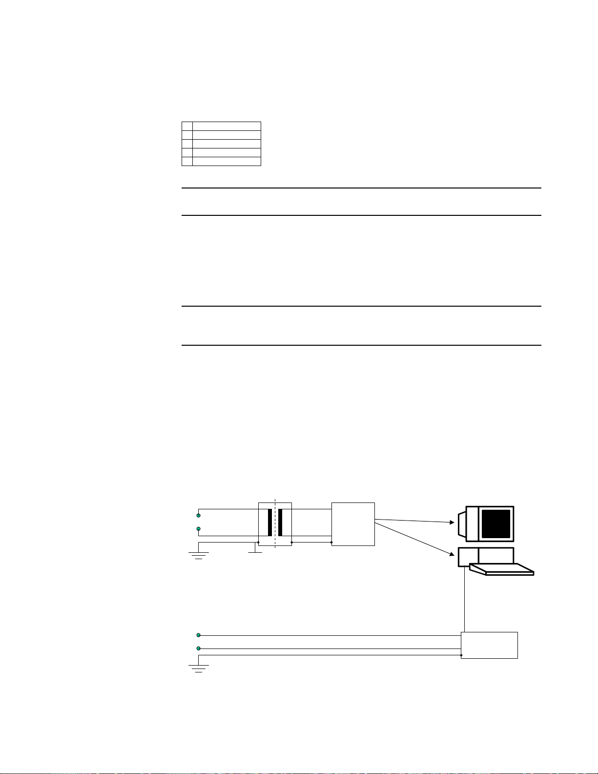
Tasks
Task 12 Connect Isolation Transformer
X Internal Server
External Server
WEB/Terminal Server
X Client Data Acq.
Other Client
Caution: Mandatory for all PCs in patient vicinity.
PCs and displays located in patient vicinity must be powered via an approved isolation
transformer that ensures mechanical fixing of the powercords and covering of unused power
outlets. Use the device power cables supplied with the transformer.
Connecting the Isolation Transformer to the Mains Power Supply and UPS
Caution: You must connect the devices in the order described below. If you connect the devices
in the wrong order, leakage currents exceeding the regulatory limits can occur.
Connect the devices in the following order:
1. Connect the isolation transformer to the main power supply.
2. Connect the isolation transformer to the UPS.
3. Connect the UPS to the PC.
Connecting the Cables
To connect the cables, open the metal clips at the transformer outlets, insert the cables then
close the clips to secure the cables. The configuration in Figure 5-1. Isolation Transformer
shows a typical OB TraceVue system comprising of an isolation transformer, UPS, PC with
display and fetal monitor:
~
Medical
Isolation
Transformer
~
UPS
RS232
Fetal Monitor
Figure 5-1 Isolation Transformer
93050913 New System Setup 5-17
Page 80

Tasks
Task 13 Connect Fetal Monitors
X Internal Server
External Server
WEB/Terminal Server
X Client Data Acq.
Other Client
Fetal Monitors are connected to the OB TraceVue system
directly via PC COM Ports or
through a serial port server.
There is no need to power a fetal monitor via either the server UPS, a client UPS, or an
isolation transformer.
For details about cables and protocol converters, refer to Connecting Fetal Monitors on
page 6-3.
Caution: Do not connect a fetal monitor directly to the server except in a small system, that is a
system with no more than 20 clients.
Caution: When connecting serial devices to the server and all four serial ports are in use, and
the UPS is offline: In the event of a power failure, the UPS will power the server but
the server will not shut down automatically.
In the event of a mains power failure, shut down the server manually.
Failure to do so could cause the OB TraceVue database to become corrupted.
Task 14 Connect to Network
X Internal Server
X External Server
X WEB/Terminal Server
X Client Data Acq.
X Other Client
1. If there are two network interface cards installed locate the first network card: See NIC
Assignment on page 17-21.
2. Plug the network cable into the socket on the back of the PC. See section Connecting
to the Network on page 6-8 for details.
5-18 New System Setup
93050913
Page 81

Task 15 Connect Second Network Card (option)
X Internal Server
X External Server
X WEB/Terminal Server
Client Data Acq.
X Other Client
1. Locate the second network card: See NIC Assignment on page 17-21.
2. Connect to the card.
3. Enable the second network card (default = disabled). Refer to Second Network
Interface Card on page 17-20.
Task 16 Connect Serial Port Server (option)
X Internal Server
External Server
WEB/Terminal Server
X Client Data Acq.
Other Client
Refer to Installing and Setting up a Serial Port Server on page 6-22.
Tasks
Task 17 Connect Modem
X Internal Server
X External Server
X WEB/Terminal Server
X Client Data Acq.
X Other Client
Refer to Modems on page 4-9 for limitations regarding the number of modems connected to
OB TraceVue PCs.
Remote Trace Transmission
Refer to Setting up Remote Trace Transmission on page 6-46.
OB TraceVue Web Access through dial-up modems.
Refer to Setting up Web Access Through Dial-Up Modem on page 6-46.
Remote Access Support (internal and external server)
See Remote Support Using Terminal Services on page 9-3.
Fax Transmission
Refer to Setting Up Fax Transmission on page 6-47.
93050913 New System Setup 5-19
Page 82

Tasks
Task 18 Switch on the OB TraceVue PC
X Internal Server
X External Server
X WEB/Terminal Server
X Client Data Acq.
X Other Client
Note Make sure the internal server PC is up and running before you start the client PCs.
This allows the client to access the internal server’s CD-ROM drive if required.
1. Make sure there’s no floppy disk in the drive. At the internal server, make sure there’s
no CD-ROM in the drive.
2. Switch on the optical drives (if fitted), the PC, and the display.
Logging on to Windows
The Autologon option was set at the factory, so the Windows desktop loads automatically.
If, for some reason, the Autologon option is not set, log on as user user. Password: user.
Task 19 Check Drive Letters
X Internal Server
External Server
WEB/Terminal Server
Client Data Acq.
Other Client
Check the drive letter assignment of the hard disk, the optical drives, and the CD-ROM
drive. See Checking and Changing Drive Letters on page 17-17.
Task 20 Calibrate Lightpen
Lightpens are no longer available.
Task 21 Install Touchscreen Driver (option)
Internal Server
External Server
WEB/Terminal Server
X Client Data Acq.
X Other Client
See ELO Touchscreen on page 17-27.
Task 22 Set Up Soundcard (option)
X Internal Server
X External Server
WEB/Terminal Server
X Client Data Acq.
X Other Client
The soundcard kit is pre-installed and ready to use.
5-20 New System Setup
93050913
Page 83

Caution: The soundcard is reserved for audible alerting and has no other purpose.
Users must not play audio CDs since this may adversely affect audible alerting.
Do not install additional hardware for playback via the soundcard or install any
additional external or internal speaker(s), or install software to control audio CD
playback.
You can adjust the volume setting if necessary. See To Adjust the Volume on page 12-3.
Task 23 Install Optical Medium Changer Device Driver (option)
X Internal Server
External Server
WEB/Terminal Server
Client Data Acq.
Other Client
See Optical Medium Changers (Jukeboxes) on page 17-27.
Task 24 Set Time Zone, Local Time and Local Keyboard
X Internal Server
X External Server
X WEB/Terminal Server
X Client Data Acq.
X Other Client
You must set the time zone appropriate for the area in which you are installing this system.
Tasks
1. On all PCs:
Select the local time zone in the Control Panel.
Make sure Automatically adjust clock for daylight saving changes is not selected.
2. Internal Server/Standalone only:
Set the local date and time in the Control Panel.
Do not set the local date and time at any other OB TraceVue PC. This information is
received from the internal server.
3. If you have a non-US keyboard, set the language option accordingly. Refer to
Regional Settings on page 17-18.
Task 25 Install or Connect to Printer
X Internal Server
X External Server
X WEB/Terminal Server
X Client Data Acq.
X Other Client
See Setting Up a Printer on page 6-41.
Do not:
Install the printer driver on an internal server PC, unless this is a small system (with no
more than three clients) and all the client PCs are in the patient vicinity.
93050913 New System Setup 5-21
Page 84

Tasks
Install the printer driver on a client with data acquisition. On clients with data
acquisition connect to a shared printer.
Install the standard LaserJet printer in the patient vicinity. The standard isolation
transformer, and the UPS, are unable to power the LaserJet printer.
5-22 New System Setup
93050913
Page 85

Task 26 Set Up OB TraceVue to Work with Other CCOW Applications
X Internal Server
X External Server
WEB/Terminal Server
X Client Data Acq.
X Other Client
Task 27 Software Engineering for 3rd Party Data Access
Internal Server
X External Server
WEB/Terminal Server
Client Data Acq.
Other Client
Task 28 Software Engineering for HL7 HIS Link (option)
Internal Server
X External Server
WEB/Terminal Server
Client Data Acq.
Other Client
Tasks
93050913 New System Setup 5-23
Page 86

Tasks
Task 29 Configure Server PC Settings and System Settings
X Internal Server
External Server
WEB/Terminal Server
Client Data Acq.
Other Client
Check/Adjust Page File Size
See Windows 2000 Configuration, Server Automatic Configuration on page 17-10.
To check/adjust, start Virtual Memory.
OB TraceVue Setup
You must run the OB TraceVue Setup to check and, if necessary, adjust configuration of the
internal server PC and the OB TraceVue system. Select Only change database settings or
system settings.
See also System Settings on page 16-5.
Configure Optical Medium Changer (if connected)
Activate Storage.
Define Disk Drives (Optical Medium Changers).
Check/Adjust Number of Client PCs
Enter the Number of clients. The limits given in Table 18-2, Server Memory,
Clients, Fetal Monitors, on page 18-4 must not be exceeded
Other System and PC Settings
See System Settings on page 16-5 and Configure Settings on page 16-6.
Task 30 Configure External Server PC Settings
Internal Server
X External Server
WEB/Terminal Server
Client Data Acq.
Other Client
Do not configure the external server until you have completed configuring the internal server.
Note
Check/Adjust Page File Size
See Windows 2000 Configuration, External Database Server Automatic
Configuration on page 17-12.
To check/adjust, start Virtual Memory.
.
OB TraceVue Setup
You may run the OB TraceVue Setup at the external server PC to check and, if necessary,
adjust the settings such as use of Auto Login, or OB TraceVue Shell settings.
5-24 New System Setup
93050913
Page 87

Tasks
See also Configure Settings on page 16-6.
For systems that are NOT English, Activate the Office software as described in Activate
Office and Install Security Updates on page 6-51.
93050913 New System Setup 5-25
Page 88

Tasks
Task 31 Configure WEB/Terminal Server PC Settings (optional)
Internal Server
External Server
X WEB/Terminal Server
Client Data Acq.
Other Client
Check/Adjust Page File Size
See
Windows 2000 Configuration, External Database Server Automatic
Configuration
To check/adjust, start Virtual Memory.
on page 17-12.
Terminal Services Configuration
See Terminal Services Configuration on page 17-16
Task 32 Configure Client PC Settings
Internal Server
External Server
WEB/Terminal Server
X Client Data Acq.
X Other Client
Note Do not configure a client PC until you have completed configuring the internal server.
Check/Adjust Page File Size
See Windows 2000 Configuration, Client Automatic Configuration on page 17-14.
To check/adjust, start Virtual Memory.
Configure OB TraceVue
You may run the OB TraceVue Setup at each client PC to check and, if necessary, adjust the
settings such as port settings, use of Auto Login, or OB TraceVue Shell settings.
See Configure Settings on page 16-6.
Task 33 Install Word/Excel Templates (option)
X Internal Server
External Server
WEB/Terminal Server
Client Data Acq.
Other Client
For details see Installing Word and Excel Templates on page 6-53.
5-26 New System Setup
93050913
Page 89

Task 34 Start OB TraceVue
X Internal Server
X External Server
WEB/Terminal Server
X Client Data Acq.
X Other Client
In the Start menu click the OB TraceVue icon.
Note Do not start OB TraceVue at the WEB/Terminal server.
The WEB/Terminal server is dedicated to run only the terminal sessions initiated by
terminal client PCs.
Task 35 Configure OB TraceVue at Internal Server PC
X Internal Server
External Server
WEB/Terminal Server
Client Data Acq.
Other Client
Tasks
Finish configuring the internal server before configuring the client PCs.
Each configuration screen builds on the information provided on the previous screen.
Work through the configuration icons from left to right.
Create at least one new superuser as the user Philips is only to give you initial access to
the system and to the Philips-only configuration screen.
For details see the Instructions for Use
Note Do not use user Philips for regular operation.
Never create/edit/delete patient related data when you are logged in as Philips user.
Task 36 Configure OB TraceVue at Client PCs
Internal Server
X External Server
WEB/Terminal Server
X Client Data Acq.
X Other Client
Do not configure a client PC until you have completed configuring the internal server.
Leave OB TraceVue running at the internal server while you complete each client’s
PC Configuration and Fetal Monitor Setup screens.
93050913 New System Setup 5-27
Page 90

Tasks
Task 37 Functionality Test
X Internal Server
X External Server
X WEB/Terminal Server
X Client Data Acq.
X Other Client
Perform the Functionality Test as described in Test and Inspection Matrix on page 2-6.
Task 38 Safety Test
X Internal Server
External Server
WEB/Terminal Server
X Client Data Acq.
Other Client
Caution: Mandatory for all PCs in patient vicinity.
If the PC is in patient vicinity, perform the Safety Test as described in Test and
Inspection Matrix on page 2-6
Task 39 Network Security
X Internal Server
X External Server
X WEB/Terminal Server
X Client Data Acq.
X Other Client
By default SNMP (Simple Network Management Protocol) is disabled on all OB TraceVue
PCs. If you rely on high network security we recommend against using SNMP as the
protocol, by design, provides minimal security.
Standard firewalling practices recommend blocking the port over which SNMP operates
(UDP ports 161 and 162). If these recommendations have been followed, the vulnerability
could only be exploited by an intranet user.
Note HP TopTools and HP / Compaq Insight require SNMP.
5-28 New System Setup
93050913
Page 91

Task 40 Print and Back-Up Configuration Record
X Internal Server
External Server
WEB/Terminal Server
Client Data Acq.
Other Client
Backing-up the Configuration Record
Standalone PC: When you have finished configuring the OB TraceVue system create a
configuration backup record at the server or standalone:
From OB TraceVue by clicking
Configuration Backup can be made to floppy disk, hard disk or optical disk.
From Windows: Start the Configuration Backup Tool.
Configuration Backup can be made to floppy disk or hard disk
Store a backup of the final configuration record in the system binder (on floppy disk).
For more information refer to Configuration Backup (Internal Server Only) on page 15-20.
Reviewing and Printing the Configuration Record
Although you cannot use the configuration text file to amend or set any installation or
configuration parameters, you should print the file and review its content:
Tasks
1. Start OB TraceVue.
2. Go to System Manager’s Configuration
3. Click Copy of Configuration, in the ACSII Format section click Export (you may change
the default name of the configuration text file before clicking Export).
4. Start NotePad, open the configuration text file.
5. Print the file.
6. Close NotePad.
7. Review the printed file with the System Manager. Store a print of the final
configuration record with the configuration backup floppy disk.
Task 41 Print out PC Installation Record
X Internal Server
X External Server
X WEB/Terminal Server
X Client Data Acq.
X Other Client
Each OB TraceVue PC automatically maintains its own installation record. This record
contains information such as the setup type (for example, network server), the installation
path and system options. To review the installation record:
Go to Start
→ Programs → OBTraceVue Support, then click Installation Record.
By default, the installation record opens as a .txt file in NotePad. You may print the
installation record from NotePad.
→ General.
93050913 New System Setup 5-29
Page 92

Tasks
Task 42 Disable Flexible Disk Drives
X Internal Server
X External Server
X WEB/Terminal Server
X Client Data Acq.
X Other Client
The floppy disk drives on all OB TraceVuePCs are disabled to prevent users attempting to
run their own software on OB TraceVue.
To change flexible disk drive settings:
1. Restart the PC.
2. Press F2 when prompted during power up to activate the BIOS SETUP.
3. At BIOS paragraph Security Features enable or disable the following values:.
Start From Flexible Disk
Flexible Disk Drives
For a reinstallation of the system, drive A has to be enabled.
Task 43 Prepare Backup of External Database
Internal Server
X External Server
WEB/Terminal Server
Client Data Acq.
Other Client
Remind the System Manager about setting up a backup schedule.
See also the System Administration and Configuration Guide.
5-30 New System Setup
93050913
Page 93

Task 44 License Balancing (optional)
Internal Server
External Server
X WEB/Terminal Server
Client Data Acq.
Other Client
Note This is only required if there you are setting up more than one WEB/Terminal Server PC.
Factory installed OB TraceVue Web Client licenses may not suit the customer’s needs.
Determine the total number of assigned client licenses, discuss the requirements with the
customer and distribute the licenses as needed.
Determine Number of Client Licenses
Perform the following steps on all WEB/Terminal Server PCs and summarize the number of
licenses.
Tasks
1. Start the Terminal Services Configuration tool: Administrative Tools
→ Terminal
Services Configuration.
2. In the left pane select Connections, in the right pane select OBTV Tcp.
3. From the menu select Action
→ Properties.
4. Choose the Network Adapter tab. The maximum number of connections is equivalent to
the number of configured Client Licenses.
Discuss Client License Distribution with Customer
When discussing the license distribution with the customer, consider the following issues:
How many users should be able to connect to which OB TraceVue system at the same
time? This gives you the number of licenses that should be assigned to each system.
The total number of licenses for all systems must equal the number of licenses ordered.
For best performance licenses should be evenly distributed among the WEB/Terminal
Server PCs of a single system.
Distribute Client Licenses
Client licenses must be adjusted at the following two places:
Terminal Services Configuration
a. Start the Terminal Services Configuration tool as described in Determine Number
of Client Licenses on page 5-31.
b. Adjust the maximum number of connections. The maximum number is 12.
Windows Client Access Licenses
a. Open Licensing.
b. In the Licensing Mode dialog select Per Seat.
93050913 New System Setup 5-31
Page 94

Tasks
Task 45 Activate License Server
Internal Server
External Server
X WEB/Terminal Server
Client Data Acq.
Other Client
Use the Terminal Server License Manager to activate Terminal Server License Server. For
detailed information about Terminal Service licensing refer to the help in the License
Manager.
Note Without activation of the License Server the OB TraceVue Web Access will be deactivated
after a grace period of 90 days.
Perform the following steps to activate the License Server:
1. Start the Terminal Server License Manager: Administrative Tools
→ Terminal Services
Licensing.
2. Select the appropriate server (activation status: not activated) in the list of available
license servers.
3. From the menu choose Action
→ Activate Server.
4. The Licensing Wizard guides you through the process of activating the License Server.
Choose Telephone as connection method and call the Microsoft license clearing house
for your region. The wizard will provide you with the appropriate telephone number.
5. Provide the clearing house with the information below:
Licensing Program: Other
Product ID: The product ID is displayed in the wizard.
Company: Name of the institution where the license server is installed.
Organizational Unit: Optional.
Last Name: Last name of the responsible person of the institution.
First Name: First name of the responsible person.
Phone: Phone number of the responsible person.
6. The clearing house will provide you with the activation key that is required for
activating the license server and finishing the wizard.
Note If activation by telephone fails (error message when finishing license server activation
process) restart the Licensing Wizard and choose World Wide Web as connection method.
The activation must be performed for all OB TraceVue WEB/Terminal Server PCs.
5-32 New System Setup
93050913
Page 95

Tasks
Task 46 Install Terminal Server Client Access Licenses (non Windows 2000 clients)
Internal Server
External Server
X WEB/Terminal Server
Client Data Acq.
Other Client
Access of PCs with non-Windows 2000 operating systems (such as Windows 98) to OB
TraceVue Web Access requires separate purchase and activation of Terminal Service
Client Access Licenses (TSCALs). The licenses must be ordered through a Microsoft sales
channel. It is the sole responsibility of the customer to order and activate these licenses.
Refer to the help of the Terminal Server License Manager for details of the Terminal Server
licensing model.
Note
Windows 2000 client PCs do not need a separate TSCAL because the operating system
already includes a preinstalled TSCAL.
Non-Windows 2000 clients can access OB TraceVue Web Access without TSCAL for
a grace period of 90 days. After that period a valid TSCAL has to be installed for these
clients.
After activating new TSCALs in the license server, non-Windows 2000 clients should
immediately connect to OB TraceVue Web Access to initiate automatic transfer of the
license. This prevents unintended usage of the licenses by other clients.
93050913 New System Setup 5-33
Page 96

Tasks
Task 47 Change Passwords
X Internal Server
X External Server
X WEB/Terminal Server
X Client Data Acq.
X Other Client
It is recommended to change the passwords of the
Windows Users (at all PCs)
Administrator
OBTV Administrator
and the OB TraceVue User
Philips
Caution: Note the passwords and store in a safe place.
If all administrator passwords got lost you need to reinstall Windows.
If the Philips password got lost see Restoring the OB TraceVue Philips Password on
page 16-9.
Task 48 Power Switch Cover and Warning Label
X Internal Server
X External Server
X WEB/Terminal Server
X Client Data Acq.
X Other Client
To help avoid the accidental uncontrolled shutdown of a PC, a plastic cover is provided
which protects the power switch on the PC front panel.
To fit the power switch cover
1. Clean the surface around the PC’s power switch.
2. Stick the power switch cover in place so its hole is over the center of the power switch.
To operate the power switch
To operate the switch, push a stiff wire (such as a bent paper-clip) into the hole in the center
of the switch cover.
Warning Label
Each PC is supplied with a sheet of adhesive labels warning not to turn off the PC.
Choose the language suitable for this installation and apply the label to the front of the PC so
it is clearly visible.
Task 49 Store System Documentation and Backups
Store all license sheets, password sheets, configuration printouts, the installation record, and
emergency repair disks in a safe location.
5-34 New System Setup
93050913
Page 97

WEB Clients
Starting a WEB Client
1. At a PC connected to the hospital network start the Windows Internet Explorer1.
2. In the Address Bar enter http://<ip address>
3. Click Start OB TraceVue Web Access.
Note The default resolution for a Web client is 800x600. To start with a different resolution open
large.htm (1024*768) or full.htm (full-screen).
Real-Time WEB Client
Installation 1. At a PC connected to the hospital network start the Windows Internet Explorer1.
2. Enter http://<ip address>/install.htm or http://<server name>/install.htm.
3. Click one of the links in the Web page to download the Software Only Setup.
4. In the File Download dialog click Run this program from its current location to start
5. Follow the instructions on screen.
TVWebSetup.exe.
2
or http://<server name>3.
WEB Clients
Check Real-Time
Connection
Note If the train engine icon is not visible check log file of the web client.
To check correct installation of a real-time client:
1. Start an OB TraceVue Web client (see Starting a WEB Client). Log in as a OB
TraceVue user with System Manager permission rights.
2. Right-click the train engine icon.
3. Type webtest. A dialog opens.
4. Click the buttons to test the sounds.
1. Windows NT, 2000, XP: you must have Windows administrator rights if you start OB TraceVue Web
Access for the first time.
2. IP address of WEB/Terminal server external NIC.
3. WEB/Terminal server must be registered in the hostname locating service (e.g. DNS) of hospital network.
93050913 New System Setup 5-35
Page 98

WEB Clients
5-36 New System Setup
93050913
Page 99

Introduction
6
Setup Details
This chapter gives details on the following setup tasks:
Installing a Client on a Cart (Mobile Client).
Connecting Fetal Monitors.
Connecting to the Network.
Installing and Configuring Remote LAN Clients.
Patient Search Tool Network Configuration.
Installing and Setting up a Serial Port Server.
Setting Up a Printer.
Setting Up Remote Connectivity.
Installing Microsoft Office 2003.
Installing Word and Excel Templates
The detailed descriptions in this chapter are referred to from Chapter 5, New System Setup.
Installing a Client on a Cart (Mobile Client)
A client PC can be cart mounted with a Series 50 IX, XM, or XMO (M1350 A/B/C) Fetal/
Maternal monitor.
Refer to the Carts Equipment Note M1325-9001D, Cart CX.
There is no provision for using the installed mouse; a touchscreen or lightpen option is
required.
Do not cart mount an OB TraceVue client PC to a Model 80300A Mobile Cart. The CRT
display is too heavy, and mounting brackets are not available.
Do NOT connect a printer to a cart mounted client.
Telemetry Unit
If telemetry is used, fix the M1310A receiving module to the top of the Cart CX, then fit the
display to the top of the receiving module using the mounting brackets provided with the
cart.
Client UPS
You must power the PC system unit and display via a UPS and an isolation transformer. The
client UPS and isolation transformer fit onto the lowest shelf of a Cart CX, and the PC
system unit on the shelf above.
93050913 Setup Details 6-1
Page 100

Installing a Client on a Cart (Mobile Client)
Make the power connections as follows:
↔ Isolation Transformer ↔ UPS ↔ PC/Display
Mains
Do not power the fetal monitor via a UPS.
Do not attempt to leave OB TraceVue running at a client (supported by the client UPS)
while the cart is disconnected from the LAN and moved to a new location.
If you move a mobile client into a storage room, reconnect the UPS to the power supply to
recharge the UPS batteries. Never leave the UPS disconnected, because the batteries will
drain down. Make sure that the system manager understands this.
Configuration
After starting OB TraceVue this client needs to be configured as Mobile. Refer to the
Instructions for Use for configuration instructions.
Moving the Cart
Whenever the mobile client is moved to a different location you need to assign the new bed
to the client PC.
To shut down a mobile client
1. Exit OB TraceVue.
You must exit OB TraceVue before moving the cart, disconnecting from the LAN, or
turning off the client.
2. Go to Start
3. When prompted that it is safe to do so, turn off the computer.
4. Disconnect the power and LAN cables.
To start a mobile client
1. Connect the power and LAN cables.
2. Turn on the PC.
3. Log on to Windows as user (if no automatic login is setup).
4. Log on to OB TraceVue.
5. At the Fetal Monitor Setup screen verify the Fetal Monitor connections and select the
correct bed labels. Assign the new bed to the new location.
→ Shutdown, select Shut down.
6-2 Setup Details
6. A cart mounted PC is configured as a mobile client. The OB TraceVue startup screen
for a mobile client is the Fetal Monitor Setup screen.
93050913
 Loading...