

Philips NE1617 Datasheet

NE1617
Temperature monitor for
microprocessor systems
Product specification 1999 Mar 19
INTEGRATED CIRCUITS
Philips Semiconductors Product specification
NE1617Temperature monitor for microprocessor systems
2
1999 Mar 19 853–2144 21065
FEA TURES
•Replacement for Maxim MAX1617 and Analog Devices ADM1021
•Monitors local and remote temperature
•Accuracy
– ± 2°C local (on-chip) sensor
– ± 3°C remote sensor
•No calibration required
•Programmable over/under temperature alarm
•SMBus 2-wire serial interface
•3V to 5.5V supply range
•70µa supply current in operating mode
•3µa (typical) supply current in standby mode
•Small 16–lead QSOP package
APPLICATIONS
•Desktop computers
•Notebook computers
•Smart battery packs
•Industrial controllers
•T elecom equipment
DESCRIPTION
The NE1617 is an accurate two-channel temperature monitor. It
measures the temperature of itself and the temperature of a remote
sensor. The remote sensor is a diode connected transistor. This can
be in the form of either a discrete NPN/PNP, such as the
2N3904/2N3906, or a diode connected PNP built into another die,
such as is done on some INTEL microprocessors.
The temperature of both the remote and local sensors is stored in a
register that can be read via a 2-wire SMBus. The temperatures are
updated at a rate that is programmable via the SMBus (the average
supply current is dependent upon the update rate—the faster the
rate, the higher the current).
In addition to the normal operation, which is to update the
temperature at the programmed rate, there is a one shot mode that
will force a temperature update.
There is also an alarm that senses either an over or under
temperature condition. The trip points for this alarm are also
programmable.
The device can have 1 of 9 addresses (determined by 2 address
pins), so there can be up to 9 of the NE1617 on the SMBus.
It can also be put in a standby mode (in order to save power). This
can be done either with software (over the SMBus) or with hardware
(using the STANDBY pin).
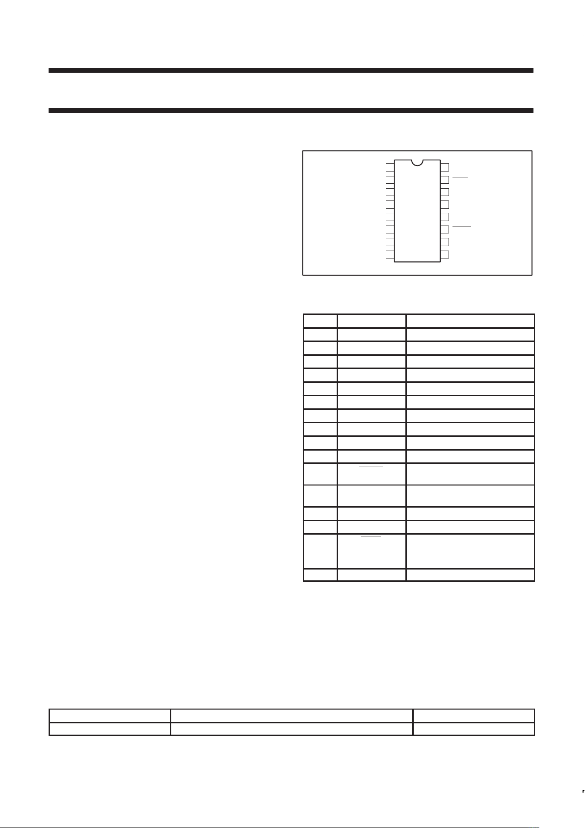
PIN CONFIGURATION
9
10
11
12
13
14
15
161
2
3
4
5
6
7
8
TEST
V
DD
D+
D–
TEST
ADD1
GND
GND
TEST
STBY
SCLK
TEST
SDATA
ALERT
ADD0
TEST
SL01202
Figure 1. Pin configuration
PIN FUNCTION DESCRIPTION
PIN # FUNCTION DESCRIPTION/COMMENTS
1 TEST Factory use only
1
2 V
DD
Positive supply
2
3 D+ Positive side of remote sensor
4 D– Negative side of remote sensor
5 TEST Factory use only
1
6 ADD1 Device address pin (3-State)
7 GND Ground
8 GND Ground
9 TEST Factory use only
1
10 ADD0 Device address pin (3-State)
11 ALERT Open drain output used as
interrupt or SMBus alert
12 SDATA SMBus serial data input/output
open drain
13 TEST Factory use only
1
14 SCLK SMBus clock input
15 STBY Hardware standby input pin
HIGH = normal operating mode
LOW = standby mode
16 TEST Factory use only
1
NOTES:
1. These pins should either float or be tied to ground.
2. VDD pin should be decoupled by a 0.1µF capacitor.
ORDERING INFORMATION
PART NUMBER PACKAGE DRAWING NUMBER
NE1617DS 16-lead QSOP package SOT519–1
Philips Semiconductors Product specification
NE1617Temperature monitor for microprocessor systems
1999 Mar 19
3
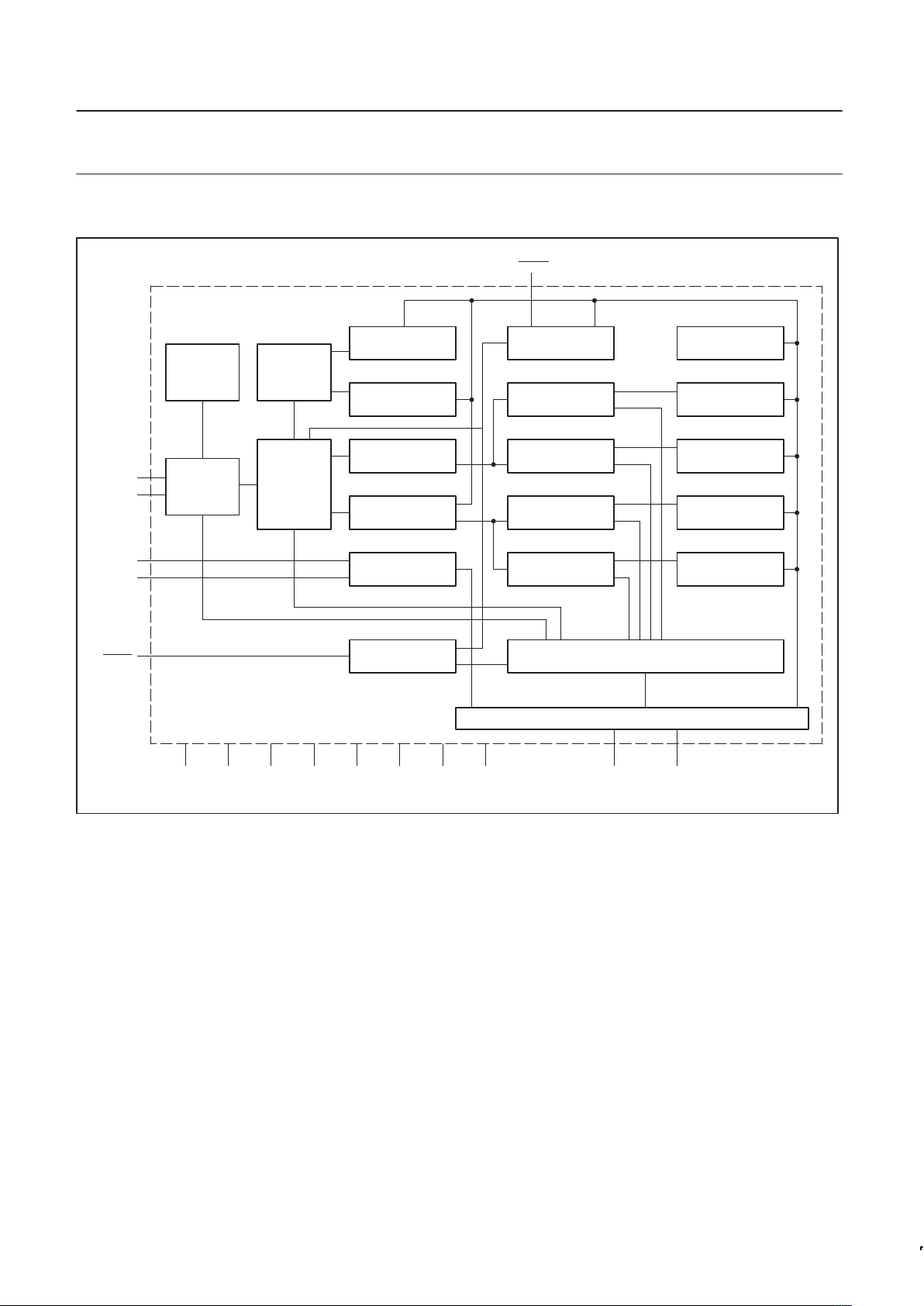
FUNCTIONAL BLOCK DIAGRAM
COMMAND POINTER
REGISTER
LOCAL TEMP HIGH
LIMIT REGISTER
LOCAL TEMP LOW
LIMIT REGISTER
REMOTE TEMP HIGH
LIMIT REGISTER
REMOTE TEMP LOW
LIMIT REGISTER
CONFIGURATION
REGISTER
LOCAL TEMP HIGH
THRESHOLD
LOCAL LOW TEMP
THRESHOLD
REMOTE HIGH TEMP
THRESHOLD
REMOTE LOW TEMP
THRESHOLD
STATUS REGISTER
SMBUS INTERFACE
ONE-SHOT
REGISTER
CONVERSION RATE
REGISTER
LOCAL TEMP
DATA REGISTER
REMOTE TEMP
DATA REGISTER
ADDRESS
DECODER
INTERRUPT
MASKING
A-TO-D
CONVERTER
CONTROL
LOGIC
LOCAL TEMP
SENSOR
ANALOG
MUX
ALERT
ADD0
ADD1
D–
D+
STDBY
SCLK SDAT ATEST16TEST13TEST9TEST5TEST1GNDGNDV
DD
SL01210
Philips Semiconductors Product specification
NE1617Temperature monitor for microprocessor systems
1999 Mar 19
4
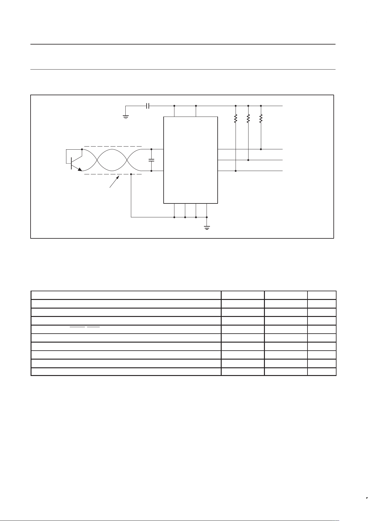
TYPICAL OPERATING CIRCUIT
215
14
12
11
10 6 7 8
SHIELDED
TWISTED PAIR
(NOTE 1)
REMOTE SENSOR
3
4
C
1
(NOTE 2)
0.1µF
V
DD
CLOCK
DATA
MICROCONTROLLER
INTERRUPT
10K10K10K
SL01203
NE1617
NOTES:
1. May be required if remote diode is in a noisy environment and/or several feet from the NE1617.
2. May be required in noisy environment. Up to 2200pF may be used.
Figure 2. Typical operating circuit
ABSOLUTE MAXIMUM RATINGS
PARAMETER MIN. MAX. UNIT
VDD to GND –0.3 +6 V
D+, ADD0, ADD1 –0.3 VDD+0.3 V
D– to GND –0.3 +0.8 V
SCLK, SDATA, ALERT, STBY –0.3 +6 V
Input current SDATA –1 +50 mA
D– current ±1 mA
Operating temperature range 0 +120 °C
Maximum junction temperature +150 °C
Storage temperature range –65 +150 °C
Philips Semiconductors Product specification
NE1617Temperature monitor for microprocessor systems
1999 Mar 19
5
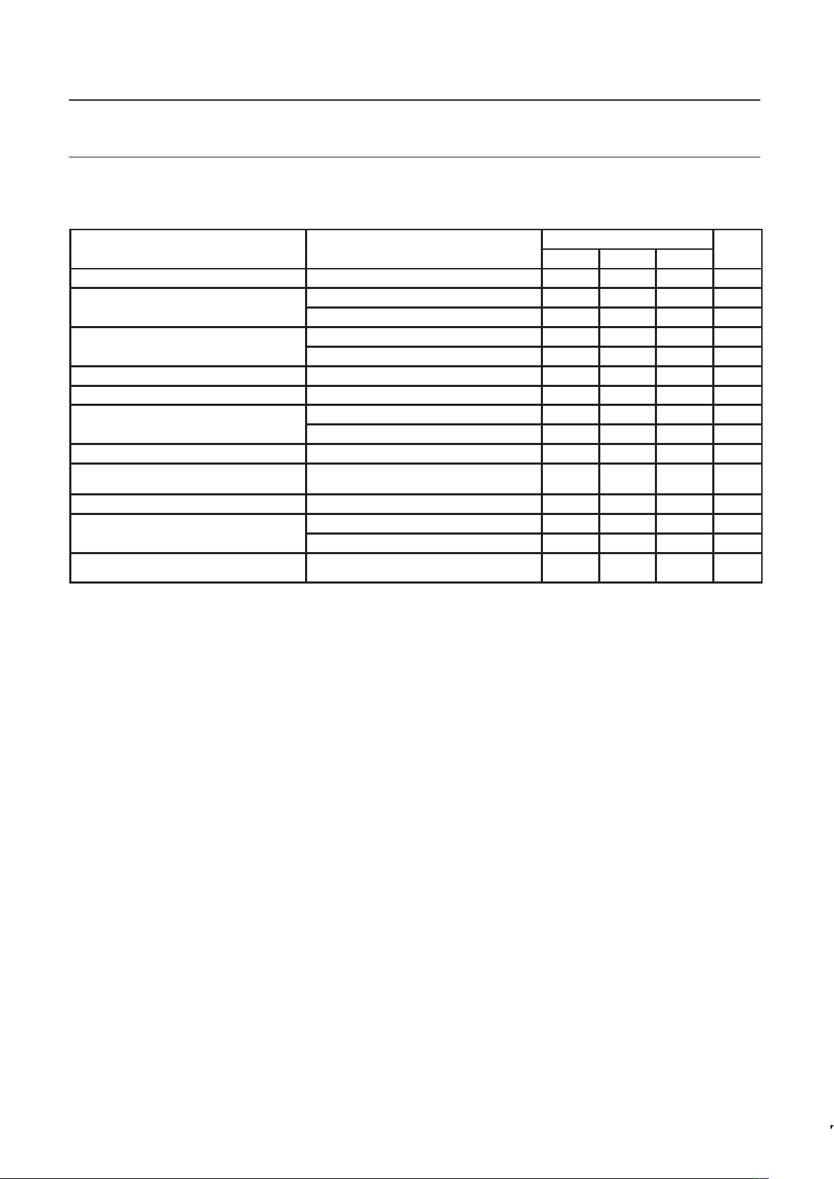
ELECTRICAL CHARACTERISTICS
VDD = 3.3V; T
amb
= 0°C to +125°C unless otherwise noted.
LIMITS
PARAMETER
CONDITIONS
MIN. TYP. MAX.
UNIT
T emperature resolution 1 °C
p
T
amb
= +60°C to +100°C < ±1 ±2 °C
Local temperature error
T
amb
= 0°C to +125°C < ±2 ±3 °C
p
T
remote
= +60°C to +100°C ±3 °C
Remote temperature error
T
remote
= 0°C to +125°C ±5 °C
Under voltage lockout VDD supply (Note 1) 2.0 2.95 V
Power-on reset threshold VDD supply (falling edge) (Note 2) 1.0 2.5 V
pp
Conversion rate = 0.25/sec 70 µA
Power supply current (average)
Conversion rate = 2/sec 180 µA
Power supply current (standby) SMBus inactive 3 10 µA
Conversion time
From stop bit to conversion complete,
both channels
170 ms
Conversion rate error Percentage error in programmed rate –30 +30 %
HIGH level 100 µA
Remote sensor source current
LOW level 10 µA
Address pin bias current
Momentary as the address is being read
(Notes 3 and 4)
160 µA
NOTES:
1. V
DD
(rising edge) voltage below which the ADC is disabled.
2. V
DD
(falling edge) voltage below which the logic is reset.
3. Address is read a power up and at start of conversion for all conversions except the fastest rate.
4. Due to the bias current, any pull-up/down resistors should be ≤ 2kΩ.
 Loading...