

Philips N74F283N, N74F283D Datasheet

INTEGRATED CIRCUITS
74F283
4-bit binary full adder with fast carry
Product specification
IC15 Data Handbook
1989 Mar 03
Philips Semiconductors Product specification
74F2834-bit binary full adder with fast carry
FEA TURES
•High speed 4-bit addition
•Cascadable in 4-bit increments
•Fast Internal carry look-ahead
DESCRIPTION
The 74F283 adds two 4-bit binary words (An plus Bn) plus the
incoming carry. The binary sum appears on the sum outputs
(Σ0–Σ3) and the outgoing carry (C
C
+20(A0+B0)+21(A1+B1)+22(A2+B2)+23(A3+B3)
IN
=Σ0+2Σ1+4Σ2+8Σ3+16C
OUT
where (+)=plus
Due to the symmetry of the binary add function, the 74F283 can be
used with either all active-High operands (positive logic) or with all
active-Low operands (negative logic). See Function Table. In case of
all active-Low operands (negative logic) the results Σ1–Σ4 and C
should be interpreted also as active-Low. With active-High inputs,
C
cannot be left open; it must be held Low when no “carry in” is
IN
intended. Interchanging inputs of equal weight does not affect the
operation, thus A0, B0, C
can arbitrarily be assigned to pins 5, 6,
IN
7, etc.
Due to pin limitations, the intermediate carries of the 74F283 are not
brought out for use as inputs or outputs. However, other means can
be used to effectively insert a carry into, or bring a carry out from, an
intermediate stage.
) according to the equation:
OUT
OUT
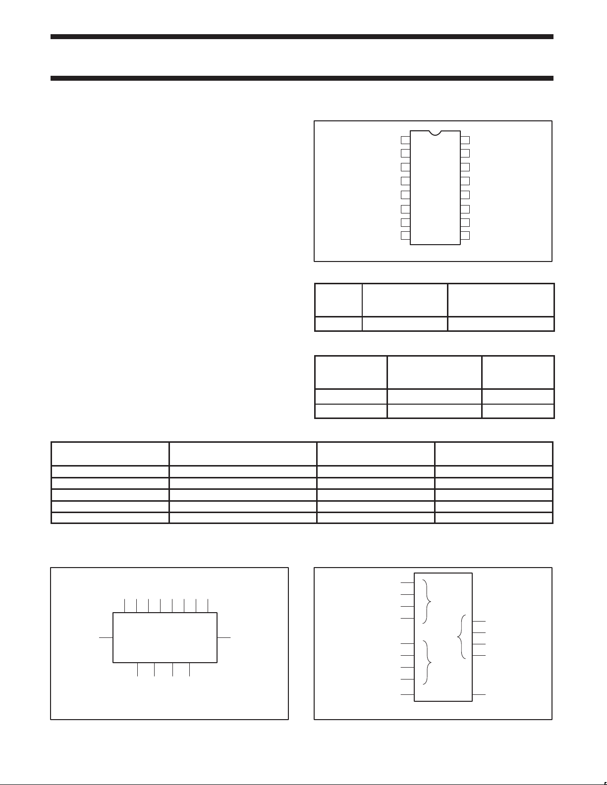
PIN CONFIGURATION
1
Σ1
2
B1
3
A1
Σ0
4
5
A0
6
B0
7
C
IN
8
GND
TYPICAL
TYPE
PROPAGATION
DELAY
74F283 6.5ns 40mA
V
16
CC
15
B2
14
A2
Σ2
13
12
A3
11
B3
10
Σ3
C
9
OUT
SF00852
TYPICAL
SUPPLY CURRENT
(TOTAL)
ORDERING INFORMATION
COMMERCIAL RANGE
DESCRIPTION
16-pin plastic DIP N74F283N SOT38-4
16-pin plastic SO N74F283D SOT109-1
VCC = 5V ±10%,
T
= 0°C to +70°C
amb
PKG DWG #
INPUT AND OUTPUT LOADING AND FAN-OUT TABLE
PINS DESCRIPTION
A0 - A3 A operand inputs 1.0/2.0 20µA/1.2mA
B0 - B3 B operand inputs 1.0/2.0 20µA/1.2mA
C
C
OUT
IN
Carry input 1.0/1.0 20µA/0.6mA
Carry output 50/33 1.0mA/20mA
Σ0–Σ3 Sum outputs 50/33 1.0mA/20mA
NOTE:
One (1.0) FAST Unit Load is defined as: 20µA in the High state and 0.6mA in the Low state.
LOGIC SYMBOL
C
VCC=Pin 16
GND=Pin 8
5 6 3 2 14 15 12 11
A0 B0 A1 B1 A2 B2 A3 B3
13 10
C
OUT
Σ3Σ2
IN
Σ1Σ0
41
97
SF00853
LOGIC SYMBOL (IEEE/IEC)
74F(U.L.)
HIGH/LOW
LOAD VALUE
HIGH/LOW
5
3
14
12
6
2
15
11
7
Σ
0
P
3
0
Q
3
0
4
3
SF00854
1
13
10
9
Σ
COCI
1989 Mar 03 853-0364 95944
2
Philips Semiconductors Product specification
1001
(10+9=19)
74F2834-bit binary full adder with fast carry
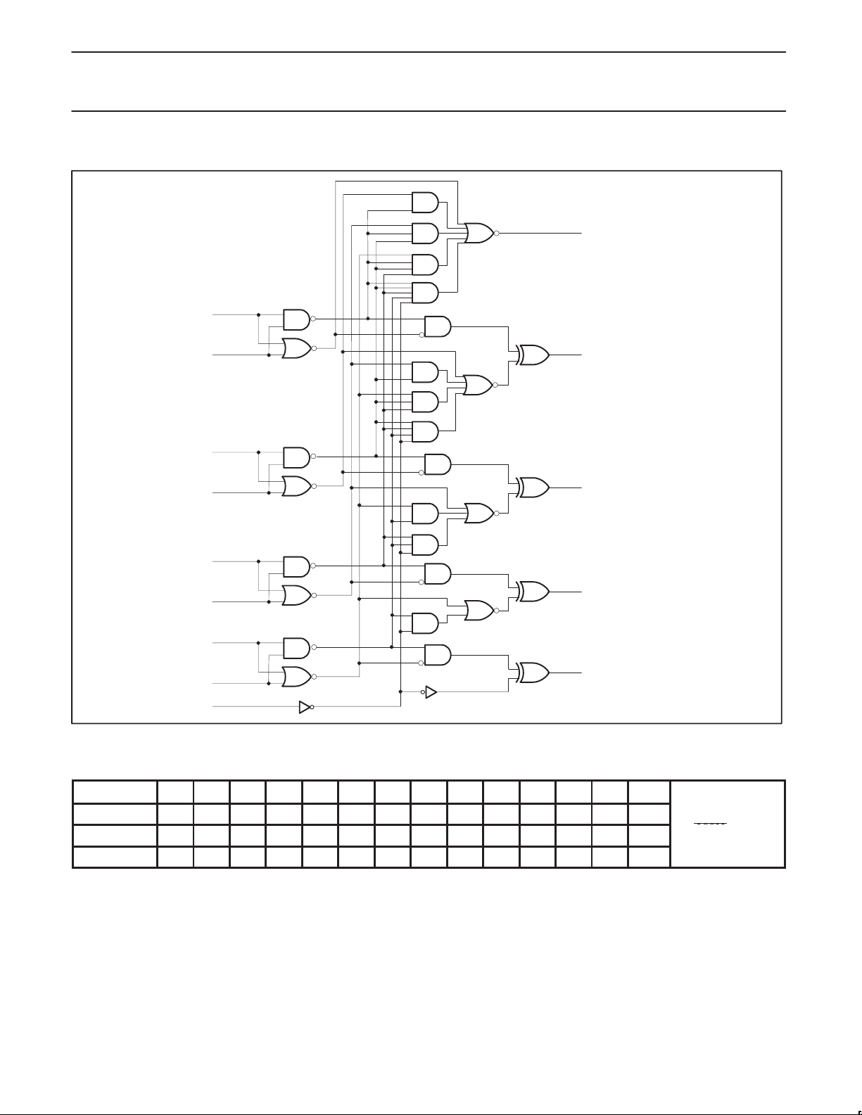
LOGIC DIAGRAM
9
C
OUT
11
B3
=Pin 16
V
CC
GND=Pin 8
12
A3
15
B2
14
A2
2
B1
3
A1
6
B0
5
A0
7
C
IN
10
13
1
4
SF00855
Σ3
Σ2
Σ1
Σ0
FUNCTION TABLE
PINS C
Logic levels L L H L H H L L H H H L L H
Active High 0 0 1 0 1 1 0 0 1 1 1 0 0 1
Active Low 1 1 0 1 0 0 1 1 0 0 0 1 1 0
H = High voltage level
L = Low voltage level
1989 Mar 03
A0 A1 A2 A3 B0 B1 B2 B3 Σ0 Σ1 Σ2 Σ3 C
IN
3
OUT
Example:
1010
10011
(carry+5+6=12)
 Loading...