

Page 1
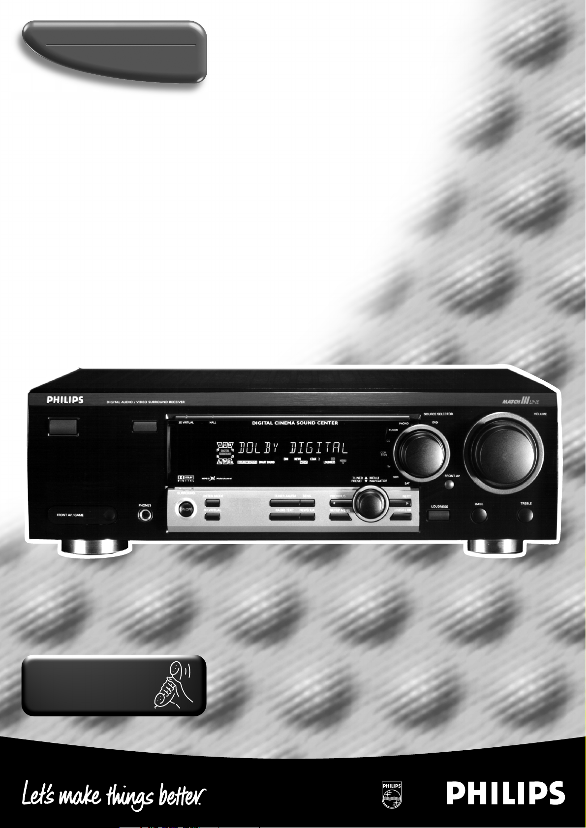
Digital surround sound receiver
FR960
MX975D
Toll Free Help Line
Ligne d’assistance en service libre
Linea de ayuada telefónica sin cargo
800-531-0039
Page 2
Know these
ssaaffeettyy symbols
t
This “bolt of lightning” indicates
uninsulated material within your unit
may cause an electrical shock. For
the safety of everyone in your household,
please do not remove product covering.
s
The “exclamation point” calls attention
to features for which you should read
the enclosed literature closely to
prevent operating and maintenance problems.
WARNING: TO PREVENT FIRE OR
SHOCK HAZARD, DO NOT EXPOSE THIS
EQUIPMENT TO RAIN OR MOISTURE.
CAUTION: To prevent electric shock,
match wide blade of plug to wide slot, and
fully insert.
For Customer Use
Enter below the Serial No. which is located
on the rear of the cabinet. Retain this
information for future reference.
Model No. ___________________________
Serial No. ____________________________
• Once your Philips purchase is registered, you’re eligible to
receive all the privileges of owning a Philips product.
• So complete and return the Warranty Registration Card
enclosed with your purchase at once.And take advantage
of these important benefits.
Return your Warranty Registration card today to
ensure you receive all the benefits you’re entitled to.
Warranty
Verification
Registering your product within 10 days
confirms your right to maximum
protection under the terms and
conditions of your Philips warranty.
Owner
Confirmation
Your completed Warranty Registration
Card serves as verification of ownership
in the event of product theft or loss.
Model
Registration
Returning your Warranty Registration
Card right away guarantees you’ll
receive all the information and special
offers which you qualify for as the
owner of your model.
Congratulations on your purchase,
and welcome to the “family!”
Dear Philips product owner:
Thank you for your confidence in Philips.You’ve selected one of the best-built,
best-backed products available today.And we’ll do everything in our power to
keep you happy with your purchase for many years to come.
As a member of the Philips “family,” you’re entitled to protection by one of the
most comprehensive warranties and outstanding service networks in the industry.
What’s more, your purchase guarantees you’ll receive all the information and
special offers for which you qualify, plus easy access to accessories from our
convenient home shopping network.
And most importantly you can count on our uncompromising commitment to
your total satisfaction.
All of this is our way of saying welcome–and thanks for investing in a Philips product.
Sincerely,
Robert Minkhorst
President and Chief Executive Officer
P.S. Remember, to get the most from your Philips product, you must
return your Warranty Registration Card within 10 days. So please
mail it to us right now!
Visit our World Wide Web Site at http://www.philipsusa.com
MAC5097
T
I
A
R
T
S
I
G
E
R
•
S
Y
Hurry!
A
D
0
1
I
N
O
N
N
E
E
D
E
D
W
I
T
H
CAUTION
RISK OF ELECTRIC SHOCK
DO NOT OPEN
CAUTION: TO REDUCE THE RISK OF ELECTRIC SHOCK, DO NOT
REMOVE COVER (OR BACK). NO USER-SERVICEABLE PARTS
INSIDE. REFER SERVICING TO QUALIFIED SERVICE PERSONNEL.
Page 3
3
English ....................................................2
Français.................................................27
Español .................................................51
EnglishFrançaisEspañol
English: This digital apparatus does not exceed the Class B
limits for radio noise emissions from digital apparatus as set
out in the Radio Interference Regulations of the Canadian
Department of Communications.
Français : Cet appareil numérique n'émet pas de bruits
radioélectriques dépassant les limites applicables aux
appareils numériques de Classe B prescrites dans le
Règlement sur le Brouillage Radioélectrique édicté par le
Ministère des Communications du Canada.
Canada
Page 4
IMPORTANT SAFETY INSTRUCTIONS – Read before operating equipment
4
English
This product was designed and manufactured to meet strict
quality and safety standards. There are, however, some
installation and operation precautions which you should be
particularly aware of.
1. Read these instructions – All the safety and operating
instructions should be read before the appliance is
operated.
2. Keep these instructions – The safety and operating
instructions should be retained for future reference.
3. Heed all warnings – All warnings on the appliance
and in the operating instructions should be adhered to.
4. Follow all instructions – All operating and use
instructions should be followed.
5. Do not use this apparatus near water – for example,
near a bathtub, washbowl, kitchen sink, laundry tub, in a
wet basement or near a swimming pool, etc.
6. Clean only with a damp cloth. The appliance should
be cleaned only as recommended by the manufacturer.
7. Install in accordance with the manufacturers
instructions. Do not block any of the ventilation
openings. For example, the appliance should not be
situated on a bed, sofa, rug, or similar surface or placed
in a built-in installation, such as a bookcase or cabinet
that may impede the flow of air through the ventilation
openings.
8. Do not install near any heat sources such as
radiators, heat registers, stoves, or other apparatus
(including amplifiers) that produce heat.
9. Do not defeat the safety
purpose of the polarized or
grounding-type plug. A polarized
plug has two blades with one
wider than the other. A grounding type plug has two
blades and a third grounding prong. The wide blade or
the third prong are provided for your safety. When the
provided plug does not fit into your outlet, consult an
electrician for replacement of the obsolete outlet.
10. Protect the power cord from being walked on or
pinched particulary at plugs, convenience receptacles,
and the point where they exit from the apparatus.
11. Only use attachments/accessories specified by the
manufacturer.
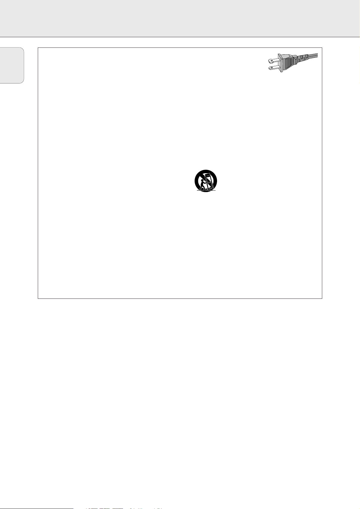
12. Use only with a cart, stand, tripod, bracket,
or table specified by the manufacturer, or sold
with the apparatus. When a cart is used, use
caution when moving the cart/apparatus
combination to avoid injury from tip-over.
13. Unplug this apparatus during lightning storms or
when unused for long periods of time.
14. Refer all servicing to qualified service personnel.
Servicing is required when the apparatus has been
damaged in any way, such as power-supply cord or plug
is damaged, liquid has been spilled or objects have
fallen into the apparatus, the apparatus has been
exposed to rain or moisture, does not operate normally,
or has been dropped.
EL 4562-E004: 99/3
AC Polarized
Plug
Page 5
5
English
GENERAL INFORMATION
This receiver is supplied including:
– an universal remote control
– 2 batteries for the remote control, size AA
– a system bus cable for the CINEMA LINK connection
– a loop antenna
– a wire antenna
– 5 loudspeakers including 5 speaker cables (MX 975D only)
– a subwoofer including a connection cable and a power cable
(only with MX 975D)
– a quick installation card (MX 975D only)
– this instruction booklet
Clean the receiver with a soft,
slightly dampened, lint-free cloth. Do
not use any cleaning agents as they
may have a corrosive effect.
Do not expose the receiver to
humidity, rain, sand or excessive heat
(caused by heating equipment or
direct sunlight).
If you have stacked the components of your system, the
receiver must be on top. Place the receiver on a flat, hard,
stabile surface. Do not cover any vents and leave 50 cm
(20 inches) above and 10 cm (4 inches) to the left and right of
the receiver clear for ventilation.
For good reception the loop antenna should not be placed on
top of or beneath VCRs, CD recorders, DVD players, TVs and
other radiation sources.
All redundant packing material has been omitted. We have
tried to make the packaging easy to separate into three mono
materials: cardboard (box), polystyrene foam (buffer) and
polyethylene (bags, protective foam sheet).
Your set consists of materials which can be recycled if
disassembled by a specialized company. Please observe the
local regulations regarding the disposal of packing materials,
dead batteries and old equipment.
Manufactured under license from Dolby Laboratories.
“DOLBY”, “DOLBY DIGITAL”, “PRO LOGIC” and the double-D
symbol 2 are trademarks of Dolby Laboratories. Confidential
unpublished works. © 1992–1997 Dolby Laboratories. All
rights reserved.
Trademark acknowledgement
Environmental information
Setup
Maintenance
Scope of supply
Safety instructions
Safety instructions......................................................................2 & 4
General information
Scope of supply..................................................................................5
Maintenance ......................................................................................5
Setup ..................................................................................................5
Environmental information.................................................................5
Trademark acknowledgement............................................................5
Controls .................................................................................................6
Remote control
Remote control use............................................................................7
Remote control buttons .....................................................................8
Programming the universal remote control.......................................9
Connectors..........................................................................................10
Connections
Audio connections............................................................................11
Digital audio connections ................................................................11
System control bus, CINEMA LINK .................................................12
Video connections............................................................................12
Power ...............................................................................................13
Speaker connections........................................................................13
TV as the center speaker.................................................................13
Antenna connections .......................................................................13
System setup
Positioning the speakers..................................................................14
Speaker setup and testing...............................................................14
Power handling ................................................................................14
Headphones .....................................................................................14
Subwoofer (MX 975D only)
Controls ............................................................................................15
Connectors .......................................................................................15
Connections......................................................................................15
Adjustment.......................................................................................15
Operation..........................................................................................15
Display.................................................................................................16
Menus
Receiver menu..................................................................................17
TV menu ...........................................................................................18
Source selection
SOURCE SELECTOR..........................................................................19
Reassigning a source selection.......................................................19
Using one source selection for two or more appliances ................19
Playback, recording
Playing a source...............................................................................20
Adjusting the sound.........................................................................20
Recording from a source..................................................................20
Recording from the digital output ...................................................20
Surround sound
About surround sound......................................................................21
Switching surround sound ...............................................................21
Surround sound settings..................................................................21
Tuner
Tuning to radio stations...................................................................22
Switching FM sensitivity .................................................................22
Storing radio stations ......................................................................22
Tuning to stored radio stations........................................................23
Resorting stored radio stations .......................................................23
Naming radio stations .....................................................................23
Clearing station names....................................................................23
Technical data
Receiver............................................................................................24
Speakers (supplied with MX 975D only).........................................24
Troubleshooting
Warning............................................................................................25
Troubleshooting................................................................................25
Limited warranty
Limited warranty..............................................................................26
Page 6
6
English
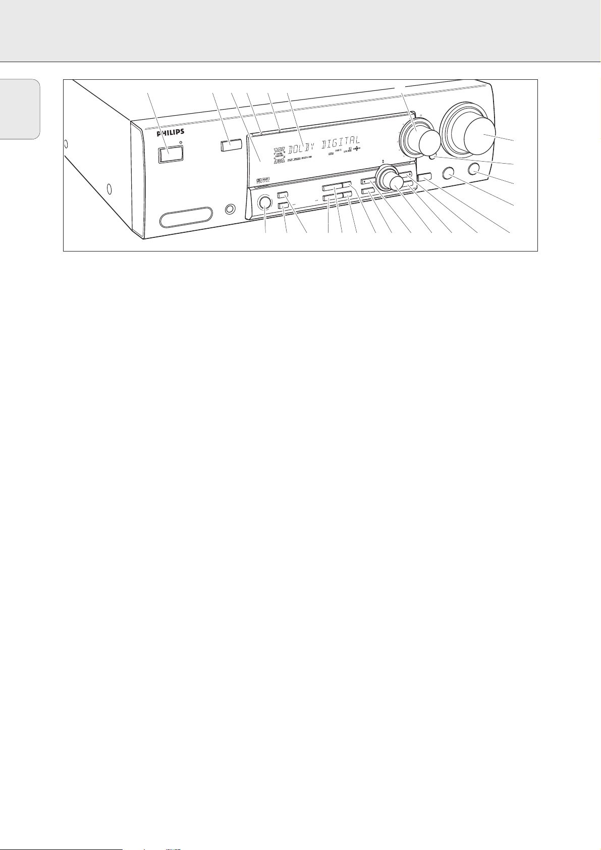
CONTROLS
1 POWER / STANDBY.......Switches the receiver on and off.
2 CINEMA LINK ................Switches on and off the system
control bus between the receiver
and the TV.
3 ..........................................Sensor for the infrared remote
control.
4 3D SURROUND ..............Control light for virtual 3D
surround.
5 HALL ................................Control light for HALL.
6 ..........................................Display
7 SOURCE SELECTOR ......Selects the different audio and
video connectors.
8 VOLUME..........................Increases and decreases the
volume level.
9 FRONT AV.......................Selects the FRONT AV / GAME
input (MX 975D only).
0 TREBLE............................Adjusts the treble when used in
combination with VOLUME.
! BASS ...............................Adjusts the bass when used in
combination with VOLUME.
@ LOUDNESS .....................Switches LOUDNESS on and off.
# NEXT 2 ...........................TUNER: searches radio stations.
MENU: switches to the next
menu level.
$ ENTER / OK.....................Confirms selected menu values.
% TUNER PRESET X MENU NAVIGATOR
TUNER: switches to the next and
previous stored radio station.
MENU: moves upwards and
downwards.
^ 1 PREV. / EXIT TUNER: searches radio stations.
MENU: switches to the previous
menu level.
& SETUP MENU ................Switches the menu on and off.
* SENS. ..............................Switches between low and high
tuner sensitivity.
( DISPLAY..........................Switches the brightness of the
display.
) TUNER BAND ................Switches the wavebands of the
tuner.
¡ NAME/FREQUENCY ......Switches between name and
frequency display.
™ SURR. MODE..................Switches through the different
surround effects.
£ 3D SURROUND ..............Switches virtual 3D surround on
and off.
≤ SURROUND ON/OFF .....Switches the surround sound on
and off.
1 234 56 7
POWER / STANDBY
FRONT AV / GAME
CINEMA LINK
PHONES
3D SURROUND
SURROUND
HALL
SURR. MODE
3D SURROUND
ON/OFF
VOLUME
TREBLE
DIGITAL CINEMA SOUND CENTER
TUNER BAND
DIGITAL SOUND PROCESSING
NAME/FREQUENCY
DUET CORE
SENS.
DISPLAY
PREV. / EXIT
SETUP MENU
SOURCE SELECTOR
D
DV
PHONO
TUNER
CD
CDR /
TAPE
TV
VCR
SAT
MENU
TUNER
NAVIGATOR
PRESET
NEXT
TER / OK
LOUDNESS
AV
BASS
^
8
9
0
!
@#$%&*()¡™£≤
Page 7
7
English
REMOTE CONTROL
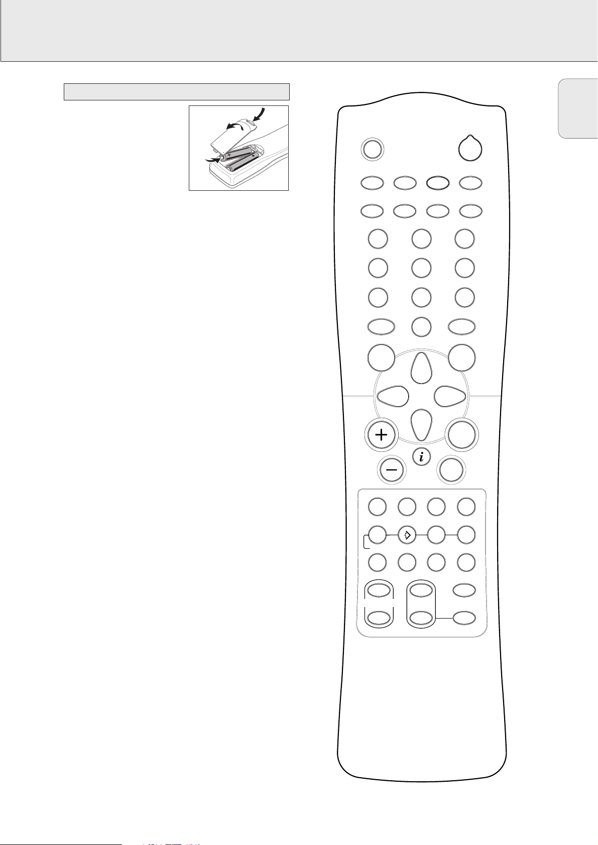
Open the battery compartment
of the remote control and insert
2 alkaline batteries, type AA
(R06, UM-3).
Remove batteries if they are
dead or if the remote control
will not be used for a long time.
Batteries contain chemical substances, so they should
be disposed of properly.
The buttons on the remote control work the same way as the
corresponding ones on the receiver.
Important!
You have to press a source button for longer than 2 seconds
to switch the sound source on the receiver. Pressing a source
button for less than 2 seconds will only switch the remote
control to use the commands for the selected product.
The remote control remains tuned to the selected source until
another source button on the remote control is pressed. This
enables you to operate additional sources (i. e. winding a
tape) without changing the source on the receiver.
Remote control use
GUIDE
MUTE
H
PHONO
TV
1
4
7
MENU
2
TUNER
VCR
CD CDR/TAPE
SAT
2
5
8
DVD
3
6
9
CABLE BOXCINEMA LINK
0
OK
É
SOUND
±
T-C
SURR.
ON/
OFF
TEST TONE
TV
AA
NEWS/TA
CHANNEL/TRACK LOUDNESS
íë
REC CANCEL FR.D. INDEX
AUDIO
DVD
DISC
REAR
+
SUB WOOFER
-
CHANNEL
Ç
Å
3D SURR.NIGHT
SURR. MODE
+
-
Page 8
8
English
REMOTE CONTROL
H MUTE .....................Mutes the sound of the receiver.
2 ................................Switches the receiver to standby.
PHONO, TUNER, CD,
CDR/TAPE, TV,
VCR, SAT, DVD..............Switches the remote control to the
commands of the different products.
Selects the sources if pressed longer
than 2 seconds. SAT only works with
digital satellite receivers.
1–0................................Keys in numbers for tracks, stations or
frequencies. Numbers consisting of
two figures must be keyed in within
2 seconds.
CINEMA LINK...............Switches the system connection
between the receiver and the TV on
and off.
CABLE BOX...................(USA only) Switches the remote
control to the cable box codes.
MENU GUIDE ..............TUNER: Switches the receiver menu
on and off.
DVD, TV: Switches the DVD/TV menu
on and off.
OK.................................Confirms menu options.
Arrow buttons ..............TUNER: Moves in the menus.
Right/left arrows are tuning up/down.
CD, CDR: Left/right arrows are
searching backwards/forwards,
up/down arrows are selecting the
next/previous track.
+A...........................Increases the receiver volume.
-A...........................Decreases the receiver volume.
i NEWS/TA.................TUNER: Without function.
TV: Switches teletext on and off.
SAT: Switches the information text on
and off.
ÉATV ......................Increases the TV volume.
CD, CDR, VCR, DVD: Starts playback.
ÇATV ......................Decreases the TV volume.
CD, CDR, VCR, DVD: Stops playback.
í
CHANNEL/TRACK
...Selects the previous preset tuner
station.
VCR: Rewinds the tape.
CD, CDR, DVD: Selects the previous
track.
TV: Selects the previous channel.
ë
CHANNEL/TRACK
...Selects the next preset tuner station.
VCR: Fast forwards the tape.
CD, CDR, DVD: Selects the next
track.
TV: Selects the next channel.
LOUDNESS ...................Switches LOUDNESS on and off.
±SOUND....................Scrolls through the different smart
sounds.
REC, DVD AUDIO..........CDR, VCR: Starts recording.
DVD: Switches audio tracks.
CANCEL, DVD ...........CD, CDR, SAT, VCR: Clears a
program, cancels selections.
DVD: Switches the view angle.
FR.D., DVD Å .............TUNER: Switches to FREQUENCY
DIRECT.
CD, CDR, VCR, DVD: Pauses
playback.
INDEX, DVD T-C............VCR: Switches the index search on
and off.
SAT: Switches the themes on and off.
DVD: Switches between title and
chapter.
DISC..............................CD-, CDR-, DVD-Changers:
Switches to the next disc.
NIGHT...........................Switches NIGHT MODE on and off.
3D SURR.......................Switches virtual 3D surround on and off.
SURR. ON/OFF..............Switches SURROUND SOUND on and
off.
+/- SUBWOOFER...Increases/decreases the subwoofer
volume.
+/- REAR ...............Increases/decreases the volume of the
rear speakers. While test tone is on,
the volume of the speakers you are
hearing can be increased/decreased
with these buttons.
SURR. MODE................Scrolls through the different surround
modes.
TEST TONE ...................Switches the test tone on and off.
While test tone is on, the volume of
the speakers you are hearing can be
increased/decreased with
+/- REAR.
Remote control buttons
Page 9

9
English
REMOTE CONTROL
You can identify the universal remote control by the
inscription Multibrand/Universal.
The universal remote control must be programmed to use the
codes for your appliances of different brands. This is done by
keying in a 4-digit code or by scanning the codes until the
correct one is found. We recommend to using the 4-digit
code. This method is faster and more reliable. The code
scanning method should be used only if you cannot find the
code for one of your appliances. The codes are listed at the
end of this book.
Important!
Use the remote control buttons for programming, not the
buttons of the receiver or other appliances.
Programming with the 4-digit code
1 Keep the source button for the appliance which should be
controlled and2 pressed for 3 seconds.
2 Key in the 4-digit code for the appliance (codetable at the
end of the booklet).
Notes: – If more than 4 digits are entered, the remote control
will recognize only the ones keyed in first.
– If you do not key in a code within 30 seconds the
remote control will switch off the programming
function without changing the code.
– To program a new appliance, simply overwrite the
old code by entering a new one.
Scanning the codetable
1 Switch on the appliance which should be controlled.
2 Keep the source button for the appliance which should be
controlled and2 pressed for 3 seconds.
3 Press and release 2 again.
yThe remote control sends the codes for channel up or
standby (depending on the selected source) for one
brand after the other.
4 As soon as the appliance reacts – switches to the next
channel or to standby – press 2 to confirm the code.
yThe identified code will be used.
• If the set does not react within 2 minutes, the code for this
appliance is not stored in the remote control. The code of
the remote control will remain unchanged.
Note: When taking out the batteries of the remote control for
more than 1 minute the codes must be reprogrammed.
Once you have found and tested the codes for your various
appliances, you may want to write them down here.
PHONO..........................................
TUNER...........................................
CD .................................................
CDR/TAPE .....................................
TV..................................................
VCR ...............................................
SAT................................................
DVD...............................................
CABLE BOX ...................................
Resetting the remote control
1 Keep one of the source buttons and 2 pressed for
3 seconds.
2 Key in the 3-digit code 981.
yThe remote control is now reset to all its original Philips
codes.
Programming the universal remote control
Page 10
10
English
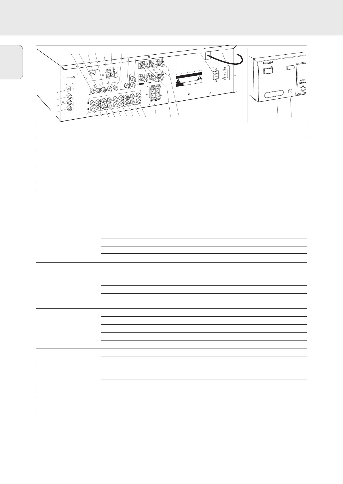
CONNECTORS
Connectors Connectors name Connect to:
6.3 mm headphone jack 1 PHONES A headphone with a 6.3 mm plug.
at the front.
Audio and video inputs 2 FRONT AV / GAME Audio and video out jacks of appliances such as video cameras
at the front (MX 975D only). and game consoles.
FRONT SPEAKERS 3 R, L Right and left front speaker.
4 CENTER Center speaker.
SURROUND SPEAKERS 5 R, L Right and left surround speaker.
AUDIO IN/OUT 7 CDR/TAPE OUT Input of a CD recorder or a tape deck.
8 CDR/TAPE IN Output of a CD recorder or a tape deck.
9 CD IN Output of a CD player.
0 SAT IN Output of a satellite system.
! VCR OUT Input of a video recorder.
@ VCR IN Output of a video recorder.
# TV IN Output of a TV.
$ PHONO IN Output of a turntable with MM coil.
( PHONO GND f Ground cable of a turntable.
DIGITAL AUDIO IN/OUT % COAX OUT Coaxial input of digital appliances such as CD recorders or
MD recorders.
^ COAX 2 IN Coaxial output of digital appliances.
& COAX 1 IN Coaxial output of digital appliances.
* OPTICAL IN Optical output of digital appliances such as DVD players, CD players,
CD recorders or MD players.
VIDEO IN/OUT ) DVD IN Output of a DVD player.
¡ MON OUT Input of a monitor (e. g. the TV).
£ VCR IN Output of a video recorder.
≤ VCR OUT Input of a video recorder (for recording).
§ SAT IN Output of a satellite system.
Antenna connectors ™
AM LOOP
Frame antenna supplied.
∞ FM 300 Ω Wire antenna supplied or exterior antenna.
Preamplified outputs 6 CENTER PRE-OUT Input of a TV when it is used as the center speaker (only possible
when the CINEMA LINK system bus is connected).
≥
SUBWOOFER PRE-OUT
Input of a powered subwoofer.
System control bus • CINEMA LINK System control bus jacks of a Philips TV with CINEMA LINK.
Power outlets ª AC OUTLET Supplies same voltage as mains. Up to 120 W/1A total permitted
(not on all versions) load.
Power cord º After all other connections have been made, connect the
power cord to the wall outlet.
)¡™ £≤∞ §≥ ª º
ANTENNA
FM 300 Ω
(
*
&
^
%
PHONO GND.
DIGITAL
AUDIO
IN/OUT
OPTICAL IN
COAX 1 IN
COAX 2 IN
COAX OUT
AM LOOP
SAT
VIDEO IN/OUT
VCR
MON
DVD
OUT
IN
TV
PHONO
L
R
IN
IN
IN
T
OU
IN
REC
PLAY
IN/OUT
AUDIO
SATCD
VCR
IN
OUT
IN
REC
PLAY
•
120V 60 Hz
~
FRONT
SPEAKERS
R
R
EACH SPEAKER
EACHSPEAKER ≥ 6 Ω
CAUTION
RISK OF ELECTRIC SHOCK
L
SURROUND
SPEAKERS
L
≥ 6 Ω
DO NOT OPEN
RISQUE DE CHOC ELECTRIQUE
AVIS
and
Designed
European Community
Manufactured
Laboratories
"AC-3",
"DOLBY",
Symbol
Double-D
Laboratories
Dolby
developed
under
Licencing
NE PAS OUVRIR
by Philips
licence
"PRO-LOGIC"
areTrademarks
Licencing
from
Corporation.
Corporation.
CINEMA
LINK
OOFER
SUBW
PRE-OUT
CENTER
CENTER
PRE-OUT
CDR/TAPE
OUT
IN
REC
IN
PLAY
AC OUTLET
TOTAL 120W/1A MAX. SWITCHED
in the
Dolby
the
and
of
Y
B
D
AN
T
R / S
E
W
O
P
V
A
NT
O
FR
CINEMA LINK
PHONES
E
AM
/ G
1234567890!@#$
ROUND
SUR
ON/OFF
Page 11
11
English
CONNECTIONS
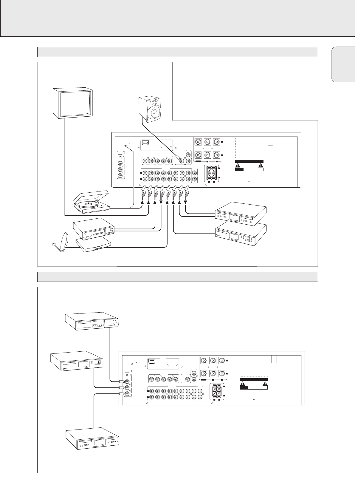
Digital audio connections
Audio connections
There are analog and digital connectors available on some
appliances. If possible use the digital connection; usually this
will result in better sound quality. See “Reassigning a source
selection” on how to use the digital connectors of the receiver.
Because of a different kind of output signal, the use of Dolby
Digital Laserdisc requires an optional AC-3 RF demodulator.
ANTENNA
CINEMA
LINK
VIDEO IN/OUT
AM LOOP
DVD MON VCR SAT
DIGITAL
AUDIO
IN/OUT
OPTICAL IN
COAX 1 IN
COAX 2 IN
COAX OUT
SUBWOOFER
PRE-OUT
IN OUT
OUT
REC
IN
IN
PLAY
PHONO
VCRTV SAT CD CDR/TAPE
AUDIO IN/OUT
L
R
IN IN
IN
PLAY
OUT
REC
IN IN
IN
PLAY
OUT
REC
PRE-OUT
CENTER
R
L
EACH SPEAKER ≥ 6 Ω
Designed and developed by Philips in the
European Community
CAUTION
RISK OF ELECTRIC SHOCK
DO NOT OPEN
AVIS
RISQUE DE CHOC ELECTRIQUE
NE PAS OUVRIR
Manufactured under licence from Dolby
Laboratories Licencing Corporation.
"DOLBY", "AC-3", "PRO-LOGIC" and the
Double-D Symbol are Trademarks of
Dolby Laboratories Licencing Corporation.
R
L
PHONO GND.
SURROUND
SPEAKERS
CENTER
FRONT
SPEAKERS
EACH SPEAKER ≥ 6 Ω
AUDIO
OUT
TURNTABLE
AUDIO IN
AUDIO OUT
IN
OUT
VCR
SAT RECEIVER
CD RECORDER
CD PLAYER
MONITOR / TV
POWERED
SUBWOOFER
CD PLAYER
CD RECORDER
DVD PLAYER
DIGITAL
AUDIO
IN/OUT
PHONO GND.
OPTICAL IN
COAX 1 IN
COAX 2 IN
COAX OUT
L
R
ANTENNA
AM LOOP
VIDEO IN/OUT
DVD MON VCR SAT
IN OUT
OUT
IN
REC
PLAY
PHONO
IN IN
AUDIO IN/OUT
VCRTV SAT CD CDR/TAPE
IN
OUT
PLAY
REC
IN
IN IN
SUBWOOFER
PRE-OUT
IN
PLAY
CINEMA
LINK
CENTER
CENTER
PRE-OUT
OUT
REC
R
R
EACH SPEAKER ≥ 6 Ω
FRONT
SPEAKERS
EACH SPEAKER ≥ 6 Ω
L
SURROUND
SPEAKERS
L
CAUTION
RISK OF ELECTRIC SHOCK
DO NOT OPEN
RISQUE DE CHOC ELECTRIQUE
AVIS
NE PAS OUVRIR
Designed and developed by Philips in the
European Community
Manufactured under licence from Dolby
Laboratories Licencing Corporation.
"DOLBY", "AC-3", "PRO-LOGIC" and the
Double-D Symbol are Trademarks of
Dolby Laboratories Licencing Corporation.
Page 12
12
English
CONNECTIONS
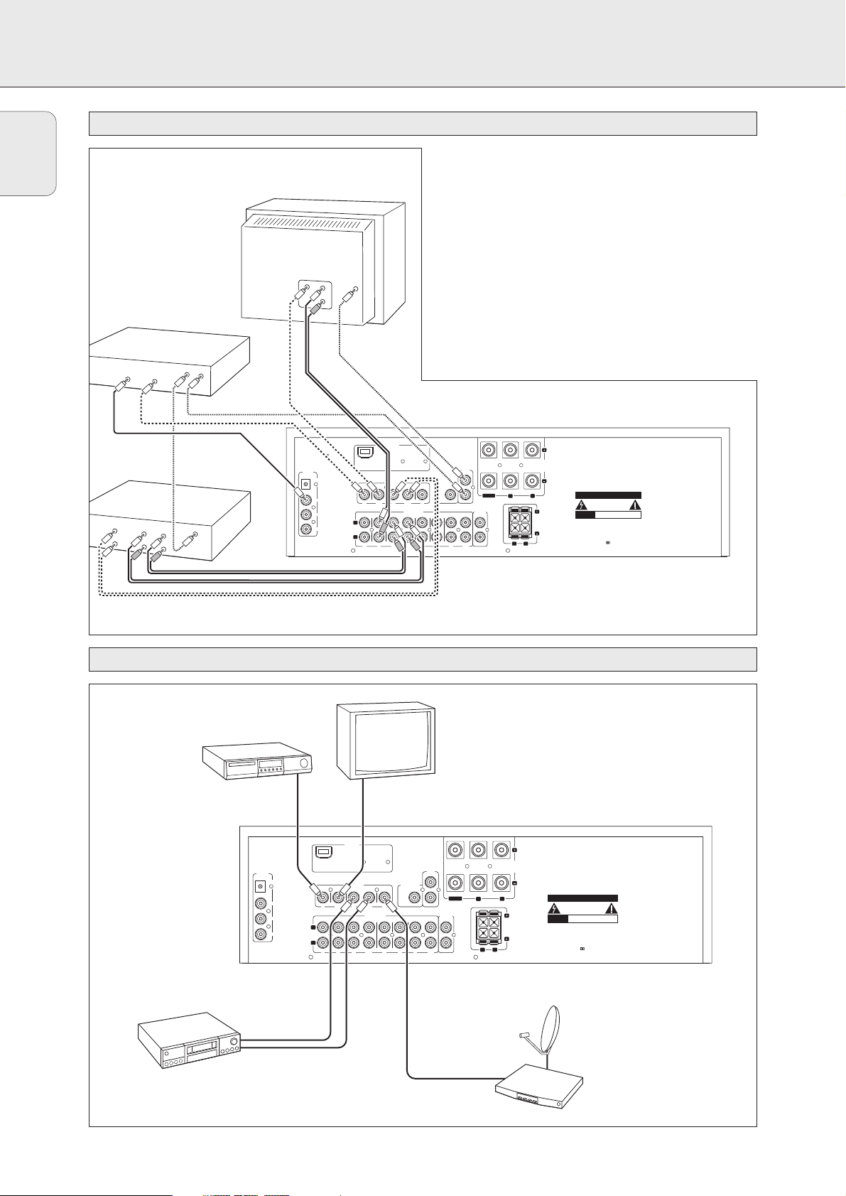
System control bus, CINEMA LINK
Video connections
If the receiver and your Philips TV (or even better in addition
a Philips VCR or DVD player) are connected with the CINEMA
LINK system bus control, some extra system benefits are
offered:
– Upon starting a source the system will automatically
switch to that input.
– You may control the system via the TV screen. Depending
on the language of the TV, this can be done in your
preferred language.
– The TV can function as the center speaker of your system,
making a separate center speaker unnecessary.
– By pressing the standby button, you can switch the
complete Home Theater System to standby.
ANTENNA
CINEMA
LINK
VIDEO IN/OUT
AM LOOP
DVD MON VCR SAT
DIGITAL
AUDIO
IN/OUT
OPTICAL IN
COAX 1 IN
COAX 2 IN
COAX OUT
SUBWOOFER
PRE-OUT
IN OUT
OUT
REC
IN
IN
PLAY
PHONO
VCRTV SAT CD CDR/TAPE
AUDIO IN/OUT
L
R
IN
IN
IN
PLAY
OUT
REC
IN IN
IN
PLAY
OUT
REC
PRE-OUT
CENTER
R
L
EACH SPEAKER ≥ 6 Ω
Designed and developed by Philips in the
European Community
CAUTION
RISK OF ELECTRIC SHOCK
DO NOT OPEN
AVIS
RISQUE DE CHOC ELECTRIQUE
NE PAS OUVRIR
Manufactured under licence from Dolby
Laboratories Licencing Corporation.
"DOLBY", "AC-3", "PRO-LOGIC" and the
Double-D Symbol are Trademarks of
Dolby Laboratories Licencing Corporation.
R
L
PHONO GND.
SURROUND
SPEAKERS
CENTER
FRONT
SPEAKERS
EACH SPEAKER ≥ 6 Ω
VCR
VIDEO
IN
AUDIO
OUT
L
R
CINEMA LINK
VIDEO
OUT
DIGITAL
OUT
CINEMA LINK
VIDEO
AUDIO
CINEMA LINK
IN/REC
OUT/PLAY
L
R
IN
REC
OUT
PLAY
DVD PLAYER
TV
ANTENNA
VIDEO IN/OUT
IN
PLAY
VCRTV SAT CD CDR/TAPE
IN
IN
PLAY
MONITOR / TV
IN
OUT
REC
AUDIO IN/OUT
IN IN
OUT
REC
SUBWOOFER
PRE-OUT
IN
PLAY
CINEMA
LINK
OUT
REC
CENTER
PRE-OUT
CENTER
SAT RECEIVER
FRONT
SPEAKERS
EACH SPEAKER ≥ 6 Ω
L
R
SURROUND
SPEAKERS
R
L
EACH SPEAKER ≥ 6 Ω
CAUTION
RISK OF ELECTRIC SHOCK
DO NOT OPEN
RISQUE DE CHOC ELECTRIQUE
AVIS
NE PAS OUVRIR
Designed and developed by Philips in the
European Community
Manufactured under licence from Dolby
Laboratories Licencing Corporation.
"DOLBY", "AC-3", "PRO-LOGIC" and the
Double-D Symbol are Trademarks of
Dolby Laboratories Licencing Corporation.
DVD PLAYER
DIGITAL
AUDIO
IN/OUT
OPTICAL IN
COAX 1 IN
COAX 2 IN
VCR
VIDEO OUT
VIDEO IN
COAX OUT
AM LOOP
DVD MON VCR SAT
IN OUT
PHONO
L
R
IN
Page 13
13
English
CONNECTIONS
The type plate is located on the rear of the receiver.
1 Check whether the power voltage as shown on the type
plate corresponds to your local power voltage. If it does
not, consult your dealer or service organization.
2 Connect the power cord to the power outlet.
To disconnect the unit from the power completely, remove the
power plug from the power outlet.
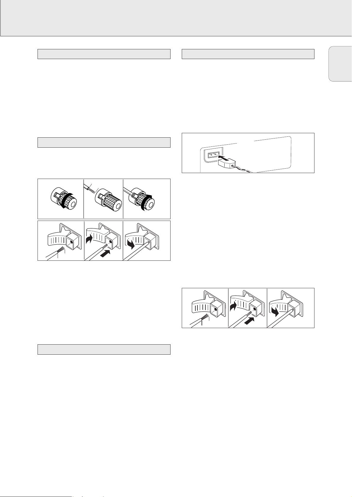
Some of the speaker connections on the receiver are screw
connectors and some are click-fit connectors. Use them as
shown below.
1 Always connect the colored (or marked) wire to the colored
terminal and the black (or unmarked) wire to the black
terminal.
2 Connect:
– Left front speaker to L (red and black)
– Right front speaker to R (red and black)
– Center speaker to CENTER (blue and black)
– Left surround speaker to SURROUND L (grey and black)
– Right surround speaker to SURROUND R (grey and black)
You may use your Philips TV with CINEMA LINK as the center
speaker. For TVs with a scart connector an additional audio
cinch-to-scart cable is needed. For TV’s with cinch connectors,
additional cinch cables are needed. These cables must be
connected to the blue CENTER PRE-OUT connector on the
back. Look into the instruction manual of your TV on how to
use it as the center speaker.
AM (MW) antenna
The loop antenna supplied is for indoor use only. Position the
antenna as far away as possible from the receiver, a TV, the
cables, a DVD player, a VCR and other radiation sources.
1 Fit the plug of the frame antenna to AM LOOP as shown
below.
2 Turn the antenna for optimum reception.
FM antenna
The wire antenna supplied can be used only to receive nearby
stations. For better reception we recommend using a cable
antenna system or an outdoor antenna.
1 Open the FM 300 Ω click-fits by pushing the lever down as
shown below.
2 Insert each wire of the antenna into one hole.
3 Close the click-fits using the lever.
4 Move the antenna in different positions for optimum
reception.
The unit complies with the FCC-Rules, Part 15.
Operation is subject to the following two conditions:
1. This device may not cause harmful interference, and
2. This device must accept any interference received,
including interference that may cause undesired
operation.
Antenna connections
TV as the center speaker
Speaker connections
Power
7 mm
1
2
3
ANTENNA
AM LOOP
8 mm
1
2
3
8 mm
1
2
3
Page 14
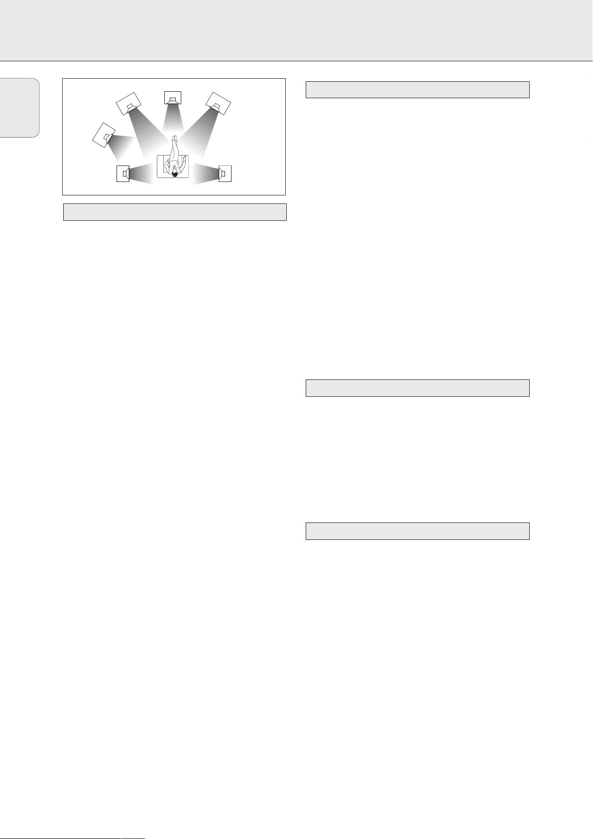
General hints for positioning
Avoid positioning the speakers in a corner or on the floor as
this will boost the bass tones too much. Placing the speakers
behind curtains, furniture, etc. will reduce the treble
response. The listener should always be able to ”see” the
speakers.
Each room has different acoustic characteristics and the
positioning possibilities often are limited. You can find the
best position for your speakers by referring to the picture
above.
As a minimum we recommend 5 speakers (2 front, a center, 2
surround) for good surround sound. It is possible to reproduce
some kind of surround sound with fewer speakers. This is
done by redirecting the signals which are foreseen for the
missing speakers to the existing ones. See “Menus” on how
to set up the receiver correctly for the number and size of the
speakers used.
Positioning the front speakers
The front speakers should be placed to the right and left in
front of the listening position like usual stereo speakers.
Positioning the center speaker
The center speaker should be placed in the center between
the two front speakers, e. g. underneath or on top of the TV.
The best height for the center speaker is the height of the
listener’s ears (while seated).
Positioning the surround speakers
The surround speakers should face each other and be in line
with, or slightly behind the listener.
Positioning the subwoofer
A subwoofer can be used to enhance the bass performance of
your system dramatically. The subwoofer can be positioned
anywhere in the room, because it is not possible to locate the
source of deep tones. Nevertheless, you should not place the
subwoofer in the middle of a room, since the bass could be
severely weakened. Do not place any object on the
subwoofer.
The relative volume of the speakers must be adjusted for
optimal surround sound. You should be at your usual listening
position when adjusting the speaker volume. See “Receiver
menus” on how to unit up the receiver for the used speakers.
1 Press POWER / STANDBY to switch on the receiver.
2 Press TEST TONE on the remote control.
y A test tone coming from the different speakers, except
the subwoofer, is heard.
3 Press +/- REAR on the remote control to
increase/decrease the volume of the actual speaker. The
best result is achieved when all speakers have equal
volume in the listening position.
4 Press TEST TONE on the remote control.
y The test tone stops.
Note: If you are not completely satisfied with the volume
settings, we recommend making minor adjustments to
them during surround sound playback.
If the receiver is used at very high power it can produce
distortions which may damage your speakers seriously. If
distortions occur, reduce the volume and the tone controls to
a level where the sound is acceptable again.
To avoid overheating of the unit a safety circuit has
been built in. Therefore your set may disconnect under
extreme conditions. If this happens, switch the unit off
and let it cool down before reusing it.
Connecting headphones to PHONES will switch off the
speakers. The receiver switches to STEREO and surround
sound will be reduced to a stereo signal which is reproducible
by standard headphones.
Disconnecting the headphones switches on the speakers
again. If you wish to enjoy surround sound again, switch the
receiver back to surround sound.
Headphones
Power handling
Speaker setup and testing
Positioning the speakers
SYSTEM SETUP
14
English
FRONT
RIGHT
RIGHT
SURROUND
(REAR)
SUBWOOFER
SURROUND
(REAR)
CENTER
FRONT
LEFT
LEFT
Page 15
15
English
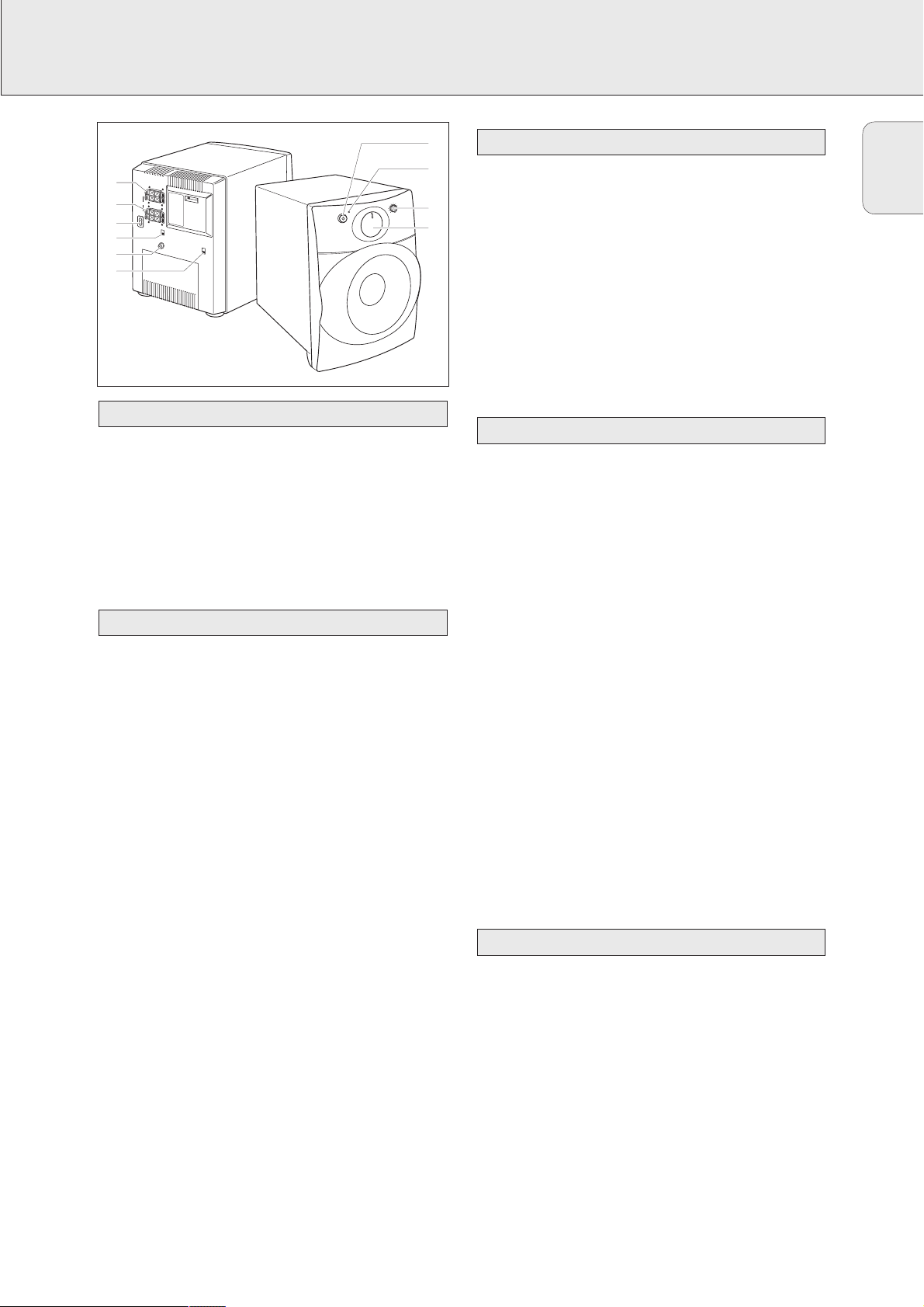
SUBWOOFER (MX 975D only)
1 STANDBY-ON y ............Switches the subwoofer on and
to standby.
2 ..........................................Status light.
3 CUT OFF FREQUENCY...Adjusts the frequency range
reproduced by the subwoofer.
4 SUBWOOFER LEVEL CONTROL
Adjusts the volume of the
subwoofer.
5 PHASE SELECTOR.........Selects the best bass
reproduction.
6 SUBWOOFER IN ............Connect to SUBWOOFER
PRE-OUT at the receiver.
7 SOURCE SELECTOR ......Selects the used signal input.
Keep at the SUBWOOFER IN
position if the receiver is
connected as described below.
8 AC MAINS......................After all other connections
have been made, connect the
power cord to AC MAINS and to
the power outlet.
9 SPEAKER OUT ...............Not used with the receiver
supplied.
0 SPEAKER IN ...................Not used with the receiver
supplied.
The type plate is located on the rear of the subwoofer.
1 Use the cinch cable supplied to connect SUBWOOFER IN to
SUBWOOFER PRE-OUT at the receiver.
2 Check whether the power voltage as shown on the type
plate corresponds to your local power voltage. If it does
not, consult your dealer or service organization.
3 Connect the power cable to the power outlet. This switches
on the power supply. Do not connect the subwoofer to the
outlets of the receiver.
Note: To disconnect completely the subwoofer from the
power, remove the power plug from the power outlet.
The subwoofer must be adjusted to your listening
environment and to your speaker setup. This only needs to be
done once.
1 Press y to switch on the subwoofer.
yThe status light turns green.
2 Play one of your favorite tracks at a normal listening level.
3 Turn SUBWOOFER LEVEL CONTROL to adjust the volume of
the subwoofer.
4 Select the reproduced frequency range by turning
CUT OFF FREQUENCY. The higher the cut off frequency is
set, the stronger the bass reproduction will be.
Note: The subwoofer reproduces the range between 35 Hz
and the frequency selected with CUT OFF FREQUENCY.
5 You may switch PHASE SELECTOR from 0° to 180°. Select
the setting that provides the sound that produces the bass
effect.
6 Press y to switch the subwoofer to standby.
yThe status light turns red.
1 Press y to switch on the subwoofer.
yThe status light turns green.
2 If the sound reproduction is noisy, reduce the volume of the
subwoofer.
3 Press y to switch the subwoofer to standby.
yThe status light turns red.
Operation
Adjustment
Connections
Connectors
Controls
0
L
L
+
IN
-
+
-
R
SPEAKER
R
L
9
8
7
6
L
+
O
UT
+
-
AC
MAINS
-
R
~
R
SO
URC
E
SELE
CTOR
S
PEA
KER IN / W
SUBWOOFER I
IR
ELES
S
N
PH
A
S
E SE
SUBWOOFER IN
L
ECT
O
R
0°
18
0
°
NDBY -
STA
O
O
W
B
U
S
R
E
W
O
P
H
G
I
H
CUT OFF FREQUENCY
C
O
L
N
E
T
V
R
E
L
O
R
L
E
F
O
O
W
B
U
S
z
H
0
5
ON
R
E
F
1
z
0 H
6
MAX
IN
M
5
1
2
3
4
Page 16
16
English
DISPLAY
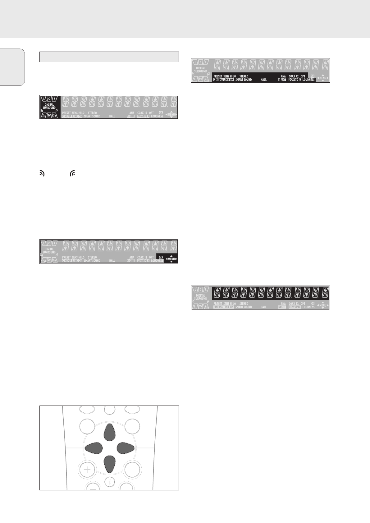
The display of the receiver is divided into 4 sections, which
are to be used for the following:
Speaker diagram
A rectangle with a letter in it shows that a speaker has been
selected in the setup menu. However, the subwoofer indicator
will only light when a subwoofer signal is available. If only a
letter is shown, this speaker is not used and its sound is
being reproduced by the other speakers.
.....virtual 3D surround
SURROUND.................surround sound is reproduced
DIGITAL SURROUND ....digital surround sound is reproduced
L, R ...........................front left and right speaker
C...............................center speaker
SL, SR .......................surround speakers
SW............................subwoofer
Menu indication
These signs show you if the menu is on or off and indicate in
which direction you may move.
MMEENNUU .......................Menu is on.
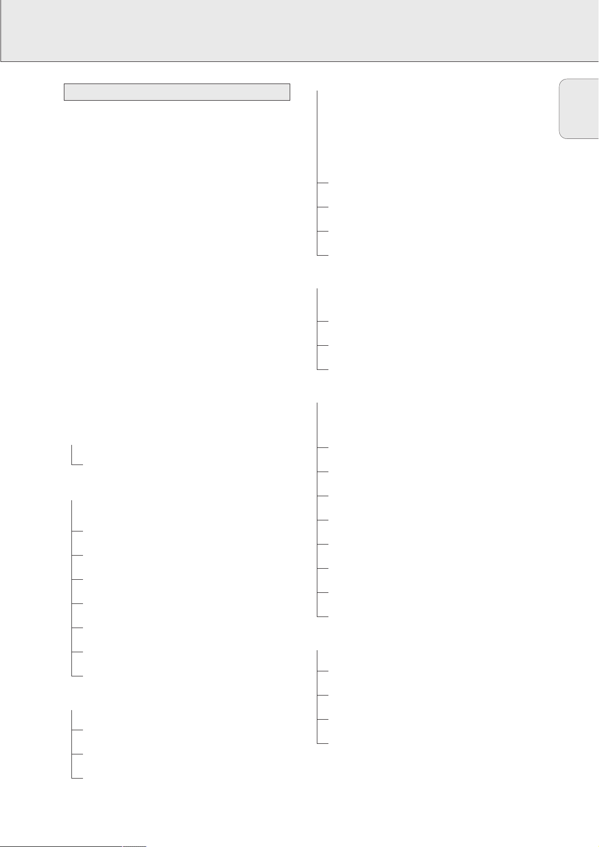
1..............................You may move backwards to the previous
menu topic using 1 PREV. / EXIT (“left”
key on the remote control).
3 .............................You may move up in an option list using
X MENU NAVIGATOR (“up” key on the
remote control).
4 .............................You may move down in an option list
using X MENU NAVIGATOR (“down” key
on the remote control).
2..............................You may move forward to the next menu
topic using NEXT 2 (“right” key on the
remote control).
OOKK.............................You may confirm the displayed value.
Status lights
Signs showing you various settings and information about the
status of the receiver.
PRESET ......................Tuner is tuned to a preset radio station.
SENS HI.....................Tuner is switched to high sensitivity.
SENS LO ..................Tuner is switched to low sensitivity.
CCIINNEEMMAA LLIINNKK OONN ......CINEMA LINK is active
STEREO......................An FM station is being received in stereo.
SMART SOUND...........One of the preset sound settings of the
receiver is being used.
HALL..........................HALL effect is on.
ANA ..........................Analog input is being used for the playing
source.
NNIIGGHHTT .......................NIGHT MODE is on.
COAX 1 ......................Coaxial digital input COAX 1 is being
used for the playing source.
COAX 2.....................Coaxial digital input COAX 2 is being
used for the playing source.
DDOOWWNNMMIIXX .................Incoming multichannel signals are being
reduced to fewer output signals
(depending on the number of speakers).
OPT ...........................Optical digital input OPTICAL IN is being
used for the playing source.
LOUDNESS .................LOUDNESS is switched on.
Information area
This area is used for feedback of the receiver, tuner
frequencies, menu options, values and scrolling text
messages.
0
Display
GUIDE
MENU
OK
É
AA
TV
Page 17
17
English
MENUS
The receiver is equipped with a menu system. The menu is
used for the setup of the receiver. The different menu options
are related to each other in a logical way. Let’s assume you
have no center speaker connected, and so you switched
CENTER SPEAKR to NO. If you try to use VOL CENTER,
a message will be scrolled that this is not possible
(INSTALL CENTER SPEAKER).
The menu always works the same way. Arrows in the display
show you the possible moving directions.
1 Press SETUP MENU.
yMENU, and * EFFECTS is displayed.
• You can exit the menu at any time by pressing
SETUP MENU.
2 Turn X MENU NAVIGATOR until the desired option (or a
value) is displayed.
3 Press NEXT 2 to choose the displayed option (or
ENTER / OK to confirm a value).
• You can leave any option (values remain unchanged) by
pressing 1 PREV. / EXIT.
Menu structure
* EFFECTS
Switches sound effects.
3D SURR
virtual 3D surround: 0…100 %
* VOL BALANCE
Adjusts the relative volume balance between the
connected speakers.
TEST TONE
Test tone: on/off
VOL FRONT-L
Volume front left speaker: –50…+50
VOL FRONT-R
Volume front right speaker: –50…+50
VOL CENTER
Volume center speaker: –50…+50
VOL REAR-L
Volume rear left speaker: –50…+50
VOL REAR-R
Volume rear right speaker: –50…+50
VOL SUBWOOFER
Volume subwoofer: –50…+50
* SPEAKR SETUP
Selects the used speakers.
SUBW PRESENT
Subwoofer present: yes/no
CENTER SPEAKR
Center speaker present: yes/no
REAR SPEAKER
Rear speakers present: yes/no
* SPEAKR SIZES
Chooses the speaker sizes of the used speakers, for
optimal sound reproduction. LARGE indicates a speaker
which can reproduce frequencies lower than 50 Hz. If
SUBW PRESENT is set to NO, FRONT SIZE can only
be set to LARGE. If FRONT SIZE is set to SMALL,
CENTER SIZE can only be set to SMALL and
consequently a subwoofer must be connected.
SUBW PRESENT
Subwoofer present: yes/no
FRONT SIZE
Left and right front speakers: small/large
CENTER SIZE
Center speaker: small/large
REAR SIZE
Rear speakers: small/large
* SPK DISTANCE
Distance between the usual listening position and the
speakers. This defines the delay time for the surround sound.
DISTANCE L/ R
Distance to front speakers: 1…10 m (3…30 ft)
DISTANCE CNTR
Distance to center speaker: 1…10 m (3…30 ft)
DISTANCE REAR
Distance to rear speakers: 1…10 m (3…30 ft)
* SELECT INPUT
Assigns the audio input connectors to the different source
selections chosen with SOURCE SELECTOR (see “Source
selection” for details).
COAX1
Digital coaxial input 1, COAX 1 IN
COAX2
Digital coaxial input 2, COAX 2 IN
OPT
Digital optical input, OPTICAL IN
SAT IN
Analog audio input SAT IN
VCR IN
Analog audio input VCR IN
TV IN
Analog audio input TV IN
CDR IN
Analog audio input CDR IN
CD IN
Analog audio input CD IN
* TUNER
Setup for preset radio stations (see “TUNER” for details).
AUTO INSTALL
Stores radio stations automatically
MAN INSTALL
Stores radio stations manually
GIVE NAME
Allows you to assign names to stored radio stations
RESHUFFLE
Resorts stored radio stations
Receiver menu
Page 18

18
English
MENUS
If the receiver is connected to a Philips CINEMA LINK TV via
the CINEMA LINK system control bus jacks (see
“CONNECTIONS”), you may use the TV to set up the system.
An option called RECEIVER will be added to the TV menu.
If CINEMA LINK is on, adjustments on the receiver will be
shown on the TV screen for a few seconds. Consult the
instruction booklet of your TV on how to use the TV menu.
The options offered may vary by TV model.
Switching the connection
• Press CINEMA LINK on or off to switch the connection
between the receiver and the TV.
yIf the connection is switched on, CINEMA LINK ON is
displayed.
Note: We recommend switching CINEMA LINK off during
recording. This avoids unwanted interruptions due to
switching TV functions.
If CINEMA LINK is switched on and the TV menu is active,
TV MENU is displayed and the menu and sound functions on
the receiver are locked.
TV menu
Page 19

19
English
SOURCE SELECTION
When selecting a source by turning SOURCE SELECTOR, the
audio and video inputs with the corresponding name are
activated. The incoming signal is reproduced by all audio and
– if the source includes a video signal – video outputs of the
receiver. It is possible to reassign a source selection to other
than these standard inputs.
Source selected........Connectors used
DVD...............................COAX 1 digital audio input and
DVD IN video input
PHONO..........................PHONO IN audio input
TUNER ..........................The tuner part of the receiver is used,
all inputs are switched off.
CD.................................CD IN audio input
CDR/TAPE.....................CDR/TAPE IN audio input
TV..................................TV IN audio input and
no video input
VCR...............................VCR IN audio input and
VCR IN video input
SAT ...............................SAT IN audio input and
SAT IN video input
If a source is selected with SOURCE SELECTOR the standard
audio input is used. To change this, the source selection must
be reassigned to another audio input.
Example: Reassigning CD from the analog CD IN audio input
to the digital COAX 2 IN audio input.
1 Choose * SELECT INPUT from the menu and press
NEXT 2.
2 Turn SOURCE SELECTOR to select the source which should
be reassigned (e. g. CD).
yThe name of the source is displayed and the light of the
source flashes.
3 Turn X MENU NAVIGATOR to select the input connectors
which should be used (e. g. CD -> COAX2).
4 Press ENTER / OK to confirm your selection.
ySTORED is displayed briefly.
5 This source selection is now using the chosen audio input
(e. g. CD uses the COAX 2 IN input connectors, COAX 2
lights when switching to CD).
You may assign more than one source to a source selection.
This can be useful when products are connected one after the
other in a chain.
Example: A VCR is connected to the TV but only the TV is
connected to the receiver. Both SOURCE SELECTOR
settings, TV as well as VCR, have to use the TV
input connectors.
1 Choose * SELECT INPUT from the menu and press
NEXT 2.
2 Turn SOURCE SELECTOR to select the source which should
be reassigned (e. g. VCR).
yThe name of the source is displayed and the light of the
source flashes.
3 Turn X MENU NAVIGATOR to select the input connectors
which should be used (e. g. VCR -> TV IN).
4 Press ENTER / OK to confirm your selection.
ySTORED is displayed briefly.
5 This source selection is now using the chosen audio input
(e. g. VCR uses the TV IN input connectors, VCR <TV
IN> is displayed briefly when switching to VCR).
Using one source selection for two or more
appliances
Reassigning a source selection
SOURCE SELECTOR
Page 20
20
English
PLAYBACK, RECORDING
1 Press POWER / STANDBY to switch on the receiver.
2 Turn SOURCE SELECTOR to select a source.
yThe name of the source is displayed.
• You can select the FRONT AV/GAME input by pressing
FRONT AV (MX 975D only).
3 Start playback of the source as usual.
• Turn VOLUME to adjust the volume.
yVOLUME and the volume level between 0 and 50 is
displayed.
1 Press BASS or TREBLE.
yBASS or TREBLE and the actual value are displayed
briefly. Then TURN VOLUME KNOB TO CHANGE is
scrolled.
2 Turn VOLUME to adjust the bass or treble.
yBASS or TREBLE and the actual value are displayed.
Note : If VOLUME is not turned within 5 seconds or if any
other control is used, the bass or treble adjustment is
switched off.
• Press ±SOUND on the remote control to scroll through
the built-in smart sounds: MOVIE, SPEECH, MUSIC,
MULTIMEDIA and PERSONAL. (PERSONAL is the
userdefined bass and treble setting.)
ySMART SOUND is displayed and the name of the chosen
sound profile is scrolled once if smart sound is on.
• Press LOUDNESS to switch on or off loudness.
yLOUDNESS is displayed if loudness is on.
If you wish to record from a source you must select it with
SOURCE SELECTOR. The incoming signal is reproduced by all
audio and – if the source includes a video signal – video
outputs of the receiver. The sound settings do not affect the
recording.
1 Turn SOURCE SELECTOR (or press FRONT AV – MX 975D only)
to select the source you want to record from.
yThe name of the source is displayed.
2 Prepare the desired recording appliance. It must be
connected to one of the outputs of the receiver.
3 Start recording on the recording appliance.
4 Start the playback of the source as usual.
Note: – The audio and video signal of VCR IN is not
reproduced by VCR OUT. The same applies to the
audio signal of CDR/TAPE IN to CDR/TAPE OUT.
– We recommend not to use the digital output
COAX OUT of the receiver to record from an analog
source. Use the analog output CDR/TAPE instead.
It is possible to connect a digital recorder to the digital output of
the receiver. In this way, all signals coming from the digital
inputs can be recorded directly on the connected audio recorder.
The receiver will also convert all signals coming from the
analogue inputs to the digital output.
The receiver can be used to record digitally a multichannel
surround sound audio signal (Dolby Digital) from, for example,
DVD to CD-R. The receiver will convert the digital multichannel
signal into a stereo signal without loss of relevant sound
information.
Notes: – Do not use the 3D SURROUND feature while making
digital recordings as this will distort the digital
audio signal.
– When recording a Dolby Digital signal, each track
must be recorded individually.
Recording from the digital output
Recording from a source
Adjusting the sound
Playing a source
Page 21
21
English
SURROUND SOUND
Surround sound gives you a completely new listening
sensation. You will have the feeling of being in the middle of
the action, because sound is coming from everywhere around
you. Look out for TV broadcasts, audio and video tapes and
discs with the 3 or 1 or marks which are
encoded for multichannel surround sound. You should prefer
Dolby Digital to get the most out of your receiver.
Notice that DVDs do not always carry full multichannel
surround. To be sure that a disc is multichannel encoded
consult your dealer.
Most ordinary stereo tapes and discs can be replayed using
surround sound settings with good results. If the reproduction
is distorted in surround mode, switch to normal stereo mode.
The availabilty of the various surround sound modes
described depends on the number of speakers used and the
incoming sound information.
With surround sound on, you can switch through the different
surround modes. Note that the possibilities are related to
speaker setup defined in the receivers menu.
If a digital surround signal is detected, the receiver will scroll
DOLBY DIGITAL.
1 Press SURROUND ON/OFF to switch on the surround sound.
yThe surround mode in use is scrolled.
2 Press SURR. MODE repeatedly to listen to the different
surround modes (if available).
yThe chosen mode and the speakers used are displayed.
If the incoming multichannel signals are reduced to
fewer output signals, DOWNMIX is displayed.
3 Press 3D SURROUND to switch on or off virtual 3D
surround .
yA light indicates if virtual 3D surround is on.
4 Press SURROUND ON/OFF to switch off the surround
sound.
ySURROUND OFF is scrolled.
HALL
The sound reproduction is enhanced and a slight echo is
added. This gives the impression of being in a large room.
Can only be used in stereo mode.
SURROUND
The surround mode enables normal surround sound
reproduction with 4 or 5 speakers. Depending on the source
material, Dolby Surround Pro Logic or Dolby Digital is
reproduced.
PRO LOGIC, DOLBY DIGITAL
In addition to SURROUND, the surround mode used –
depending on the source material – will be displayed. In case
of digital surround, the sound format AC-3 (for Dolby Digital) will
be displayed, followed by the sound channels, available on the
source (e. g. DVD).
Example: AC-3 3/2.1 Dolby Digital, 3 front channels,
2 surround channels and a
subwoofer channel.
AC-3 3/1.0 Dolby Digital, 3 front channels,
1 (mono) surround channel without
subwoofer signal.
FRONT-3 STEREO
The surround sound is muted. 3 Stereo lets you listen to
surround sound without using the surround speakers.
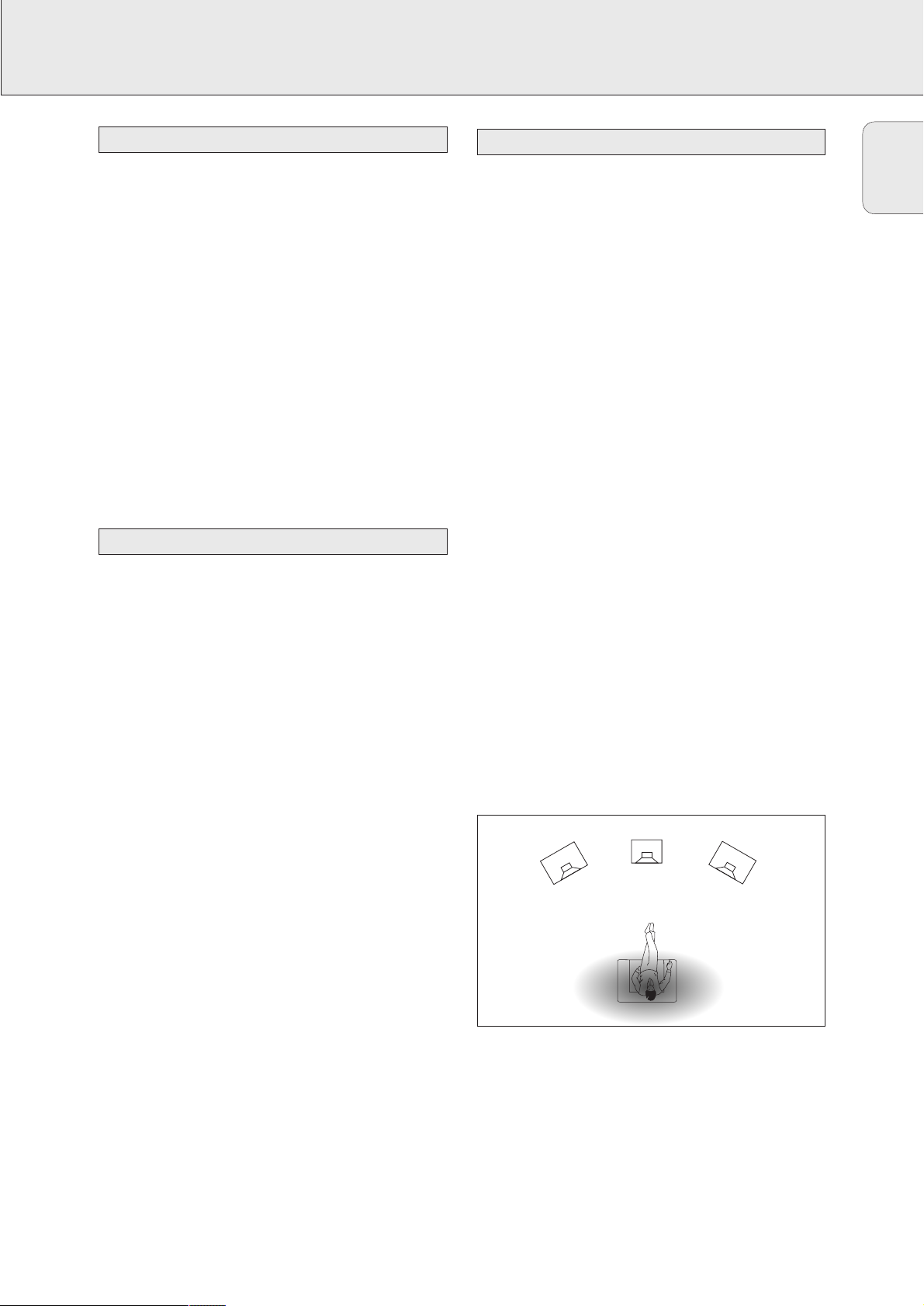
3D SURROUND
The sound of the rear channel is simulated by the front speakers.
Surround sound is simulated through the front left, right and center
speakers. The position of the listener influences the surround
effect. The area where the effect is best is shown in gray.
STEREO
All sound is reproduced and played through the front left and
right speakers. This enables standard stereo reproduction.
NIGHT MODE (only on the remote control)
The loud parts of the sound are lowered and the soft passages
are raised. You can enjoy surround sound without disturbing
sleeping children or neighbors. Night mode only works with Dolby
Digital, and only if supported by the source material.
Surround sound settings
Switching surround sound
About surround sound
CENTER
FRONT
FRONT
LEFT
RIGHT
Page 22
22
English
TUNER
You can search for radio stations by scanning the frequency
band. You can also key in the frequency of a known radio
station. If an FM station is being broadcast and received in
stereo,
STEREO is shown.
Searching for radio stations
1 Turn SOURCE SELECTOR to select the tuner.
yTUNER is displayed.
2 Select a waveband by pressing TUNER BAND repeatedly.
yThe selected waveband is displayed.
3 Keep 1 or 2 pressed for approximately 1 second.
ySEARCH is displayed and the tuner tunes to a station
with sufficient strength.
4 Repeat this procedure until you find the desired station.
• To fine tune to a weak transmitter, briefly press 1 or 2 as
often as necessary for optimum reception.
Tuning to a radio station by frequency (with the remote
control only)
1 Press TUNER.
yTUNER is displayed.
2 Press FR. D..
y_ is displayed.
3 Use 1–0 to key in the frequency of a radio station.
Notes: Only valid numbers within the frequency range of the
tuner can be keyed in.
You can switch the tuner to a lower search sensitivity, to
search only for stations with a strong signal (FM only).
1 Turn SOURCE SELECTOR to select the tuner.
yTUNER is displayed.
2 Press SENS. on the receiver.
yEither SENS HI or SENS LO is displayed for 5 seconds.
Note: While searching for radio stations, the actual sensitivity
is displayed. In this case, SENS LO means the tuner is
looking only for radio stations with a strong signal.
You may store up to 30 radio stations in the memory. The
receiver can select and program radio stations by itself or you
can choose them yourself.
Automatic programming
1 Choose * TUNER from the menu and press NEXT 2.
2 Choose AUTO INSTALL and press NEXT 2.
yThe preset number where programming will start, the
waveband and AUTO are displayed.
3 Turn TUNER PRESET X to change the preset number where
programming should start.
4 Use TUNER BAND to switch to the desired waveband.
5 Press ENTER / OK to start programming.
yAUTO INSTALL flashes and all available radio
stations are programmed, this may take a few minutes.
Programming is done when AUTO INSTALL stops
flashing.
Manual programming
1 Choose * TUNER from the menu and press NEXT 2.
2 Choose MAN INSTALL and press NEXT 2.
yA preset number, the waveband and the frequency are
displayed.
3 Turn TUNER PRESET X to change to the preset number
where the radio station should be stored.
4 Tune to the desired radio station (see “Searching for radio
stations”).
5 Press ENTER / OK to confirm your selection.
ySTORED is displayed briefly. The radio station is
programmed at the chosen preset number.
6 Select and store all desired radio stations this way.
Storing radio stations
Switching FM sensitivity
Tuning to radio stations
Page 23
23
English
TUNER
1 Turn SOURCE SELECTOR to TUNER to select the tuner.
yTUNER is displayed.
2 Turn TUNER PRESET X to select a preset radio station.
yPRESET, the preset number and station are displayed.
After programming radio stations, you might want to change
their sequence. RESHUFFLE allows you to exchange the
positions of presets.
1 Choose * TUNER from the menu and press NEXT 2.
2 Choose RESHUFFLE and press NEXT 2.
yPRESET, a preset number and station are displayed.
3 Turn TUNER PRESET X to select a preset station.
4 Press ENTER / OK to confirm the selection.
yThe selected preset number SWAP <-> and a second
preset number are displayed.
5 Turn TUNER PRESET X to select the other preset station.
6 Press ENTER / OK to confirm the exchange.
yRESHUFFLED is displayed briefly and these two
preset numbers are swapped.
It is possible to assign a name to any of the preset radio
stations.
1 Choose * TUNER from the menu and press NEXT 2.
2 Choose GIVE NAME and press NEXT 2.
yA preset radio station is displayed.
3 Turn TUNER PRESET X to select the preset to be renamed.
4 Press ENTER / OK to confirm your selection.
yThe existing name or ________ is displayed.
5 Turn TUNER PRESET X to select a letter and NEXT 2 or
1 PREV. to move to the next or previous position.
6 After you have entered the entire name, press ENTER / OK
to confirm.
ySTORED is displayed and the name is stored.
1 Use the menu option * TUNER, choose GIVE NAME.
yA preset radio station is displayed.
2 Turn X MENU NAVIGATOR to select the name to be
cleared.
3 Press ENTER / OK to confirm your selection.
4 Press 1 PREV. while the first letter is flashing.
y CL is flashing to the left of the station name.
5 Press ENTER / OK to clear the station name.
Or, if you have changed your mind,
press 1 PREV. to leave the station name as it is.
Clearing station names
Naming radio stations
Resorting stored radio stations
Tuning to stored radio stations
Page 24

24
English
TECHNICAL DATA
Subject to modification without notice.
General
Power consumption (FR 960)........................................≈ 175 W
Power consumption (FR 970)........................................≈ 195 W
Standby power consumption............................................< 2 W
Dimensions, w × h × d ............................435 × 135 × 350 mm
Weight (FR 960) ................................................................8.6 kg
Weight (FR 970) ................................................................9.4 kg
Amplifier part (0.7 % THD, 6 Ω, 1 kHz)
Output power, stereo mode (FR 960, 40 Hz–20 kHz)..2 × 50 W
Output power, surround mode (FR 960)
Front ......................................................................2 × 60 W
Center ..........................................................................60 W
Surround................................................................2 × 60 W
Output power, stereo mode (FR 970) ........................2 × 100 W
Output power, surround mode (FR 970)
Front ....................................................................2 × 100 W
Center ........................................................................100 W
Surround................................................................2 × 50 W
Bass ..................................................................±9 dB at 100 Hz
Treble ................................................................±9 dB at 10 kHz
Loudness....+6 dB at 100 Hz (-30 dB); +3 dB at 10 kHz (-30 dB)
Total harmonic distortion .........................0.05 % at 1 kHz, 1 W
Frequency response ..................................20–30,000 Hz, ±1 dB
S/N ratio ........................................................................≥ 82 dB
Stereo separation (1 kHz) ..............................................≥ 45 dB
Crosstalk (1 kHz) ...........................................................≤ -65 dB
Inputs
Linear inputs ...................................................250 mV at 47 kΩ
Front AV (FR 970, MX 975D only)...................250 mV at 22 kΩ
Phono ..................................................................5 mV at 47 kΩ
Digital coaxial ..............................................75 Ω acc. IEC 958
Outputs
Power supply AC outlets (switched) ...........totally max. 120 W
Linear outputs...................................................250 mV at 1 kΩ
Digital coaxial ..............................................75 Ω acc. IEC 958
Digital optical...................................................................toslink
Subwoofer pre-out................................................0.8 V at 1 kΩ
Center pre-out.......................................................0.8 V at 1 kΩ
Headphones....................................8–600 Ω (3 V e.m.f., 60 Ω)
Speakers ...........................................................................≥ 6 Ω
Tuner part
Wave range
FM..............................................................87.5–108.0 MHz
AM................................................................530–1,700 kHz
Sensitivity
Stereo FM ..................................................................41 dBf
Mono FM....................................................................17 dBf
Total harmonic distortion
Stereo FM ...................................................................0.8 %
Mono FM.....................................................................0.9 %
Frequency response ...................................63–12,500 Hz ±1 dB
S/N ratio
Stereo FM....................................................................55 dB
Mono FM.....................................................................60 dB
Channel separation.............................................27 dB at 1 kHz
Subject to modification without notice.
Front speakers
Impedance............................................................................6 Ω
Frequency range ...................................................40–20,000 Hz
Power handling capacity..................................................100 W
Power handling capacity – peak .....................................150 W
Sensitivity..........................................................................89 dB
Drivers ......................................1 × 5
1
⁄4" woofer, 1 × 2" tweeter
Passive radiator .................................................1 × 61⁄2" woofer
Crossover frequencies ..................................................4,000 Hz
Dimensions, h × w × d ............................421 × 219 × 191 mm
Weight..................................................................approx. 2.5 kg
Rear speakers
Impedance............................................................................6 Ω
Frequency range ...................................................40–20,000 Hz
Power handling capacity....................................................50 W
Power handling capacity – peak .....................................100 W
Sensitivity..........................................................................89 dB
Drivers ......................................1 × 5
1
⁄
4" woofer, 1 × 2" tweeter
Passive radiator .................................................1 × 6
1
⁄
2" woofer
Crossover frequencies ..................................................4,000 Hz
Dimensions, h × w × d ............................421 × 219 × 191 mm
Weight..................................................................approx. 2.5 kg
Center speaker
Impedance............................................................................6 Ω
Frequency range ...................................................75–20,000 Hz
Power handling capacity..................................................100 W
Power handling capacity – peak .....................................150 W
Sensitivity..........................................................................89 dB
Drivers ......................................2 × 4" woofers, 1 × 2" tweeter
Crossover frequencies ..................................................4,500 Hz
Dimensions, h × w × d ............................131 × 435 × 122 mm
Weight..................................................................approx. 1.6 kg
Powered subwoofer
Power consumption ...........................................................30 W
Standby power consumption.........................................< 4.5 W
Output power .....................................................................50 W
Frequency range ........................................................35–140 Hz
Input sensitivity ..............................................200 mV at 22 kΩ
Sensitivity..........................................................................89 dB
Drivers............................................................1 × 5
1
⁄4" cone type
Crossover cut-off frequencies...................................60–150 Hz
Dimensions, h × w × d ............................310 × 235 × 355 mm
Weight..................................................................approx. 7.1 kg
Speakers (supplied with MX 975D only)
Receiver
Page 25
25
English
TROUBLESHOOTING
PROBLEM POSSIBLE CAUSE SOLUTION
No sound VOLUME is not adjusted correctly. Adjust the VOLUME.
Headphones are connected. Disconnect headphones.
The wrong source is selected. Turn SOURCE SELECTOR to select the correct
source.
No sound on the One speaker is connected incorrectly. Connect the speaker properly.
left or right side
A speaker cable is damaged. Replace the cable.
Volume balance in the receiver menu is Adjust VOL FRONT-L and VOL FRONT-R
adjusted incorrectly. in the receiver menu.
Poor sound or no sound at SURROUND mode is not switched on. Press SURROUND ON/OFF to switch on the
the center or surround surround sound.
speakers
Surround and/or center speakers are not Connect the speakers properly.
(properly) connected.
Surround and/or center speakers are switched Set speaker present to YES.
off in the SPEAKR SETUP menu.
A speaker cable is damaged. Replace the cable.
Poor bass sound Speakers are not in phase. Connect the colored (or marked) wires to the
colored terminals and the black (or unmarked)
wires to the black terminals.
Bad sound Badly matching setting for the given type of Correct the sound settings on the receiver.
music or sound.
Surround sound level is The level of the surround sound is not Adjust the level of the surround sound on
too low or too high adjusted properly. the receiver.
Center sound level is too The sound level of the center channel is not Adjust the level of the center channel
low or too high adjusted properly . on the receiver.
Only center speaker is A mono signal is reproduced. Choose a different sound source or switch off
heard in Dolby Surround surround sound.
Pro Logic
Bad radio reception, Receiver or antenna is positioned near a Change the position of the interfering unit
automatic programming radiation source such as TV, CD player, or try to switch it off.
does not work properly CD recorder, DVD player, etc.
WARNING
Under no circumstances should you try to repair the
set yourself as this will invalidate the warranty. Do
not open the set as there is a risk of electric shock.
If a fault occurs, first check the points listed, before taking
the set for repair.
If you are unable to solve a problem by following these hints,
consult your dealer or service centre.
Page 26

AUDIO SYSTEM
One Year Free Labor
One Year Free Service on Parts
This product must be carried in for repair.
LIMITED WARRANTY
WHO IS COVERED?
You must have proof of purchase to receive warranty service.A sales
receipt or other document showing that you purchased the product
is considered proof of purchase.
WHAT IS COVERED?
Warranty coverage begins the day you buy your product. For one
year thereafter, all parts will be repaired or replaced, and labor is
free.After one year from the day of purchase, you pay for the
replacement or repair of all parts, and for all labor charges.
All parts, including repaired and replaced parts, are covered only for
the original warranty period.When the warranty on the product
expires, the warranty on all replaced and repaired parts also expires.
WHAT IS EXCLUDED?
Your warranty does not cover:
• labor charges for installation or setup of the product, adjustment
of customer controls on the product, and installation or repair of
antenna systems outside of the product.
• product repair and/or part replacement because of misuse,
accident, unauthorized repair or other cause not within the
control of Philips Consumer Electronics Company.
• reception problems caused by signal conditions or cable or
antenna systems outside the unit.
• a product that requires modification or adaptation to enable it to
operate in any country other than the country for which it was
designed, manufactured, approved and/or authorized, or repair of
products damaged by these modifications.
• incidental or consequential damages resulting from the product.
(Some states do not allow the exclusion of incidental or
consequential damages, so the above exclusion may not apply to
you.This includes, but is not limited to,prerecorded material,
whether copyrighted or not copyrighted.)
• a product that is used for commercial or institutional purposes.
WHERE IS SERVICE AVAILABLE?
Warranty service is available in all countries where the product is
officially distributed by Philips Consumer Electronics Company. In
countries where Philips Consumer Electronics Company does not
distribute the product, the local Philips service organization will
attempt to provide service (although there may be a delay if the
appropriate spare parts and technical manual(s) are not readily
available).
MAKE SURE YOU KEEP...
Please keep your sales receipt or other document showing proof of
purchase.Attach it to this owner’s manual and keep both nearby.Also
keep the original box and packing material in case you need to return
your product.
BEFORE REQUESTING SERVICE...
Please check your owner’s manual before requesting service.
Adjustments of the controls discussed there may save you a service
call.
TO GET WARRANTY SERVICE IN U.S.A.,
PUERTO RICO OR U.S. VIRGIN ISLANDS...
Take the product to a Philips factory service center (see enclosed
list) or authorized service center for repair.When the product has
been repaired, you must pick up the unit at the center. Centers may
keep defective parts. (In U.S.A., Puerto Rico and U.S.Virgin Islands, all
implied warranties, including implied warranties of merchantability
and fitness for a particular purpose, are limited in duration to the
duration of this express warranty. But, because some states do not
allow limitations on how long an implied warranty may last,this
limitation may not apply to you.)
TO GET WARRANTY SERVICE IN CANADA...
Please contact Philips at:
1-800-661-6162 (French Speaking)
1-800-363-7278 (English Speaking)
(In Canada, this warranty is given in lieu of all other warranties. No
other warranties are expressed or implied, including any implied
warranties of merchantability or fitness for a particular purpose.
Philips is not liable under any circumstances for any direct, indirect,
special, incidental or consequential damages, howsoever incurred,
even if notified of the possibility of such damages.)
REMEMBER...
Please record the model and serial numbers found on the product
below.Also, please fill out and mail your warranty registration card
promptly. It will be easier for us to notify you if necessary.
MODEL # ________________________________________
SERIAL # ________________________________________
EL4965E005 / MAC 4110 / 1-97
This warranty gives you specific legal rights.You may have other rights which vary from state/province to state/province.
Philips Service Solutions Group, P.O. Box 2976, Longview,Texas 75606, (903) 242-4800
 Loading...