

Page 1
MX 16-slice
P e r f o r m a n c e T e s t I n s t r u c t i o n s
4550 193 03381
Revision C
This document and the information contained in it is proprietary and confidential information of Philips Healthcare ("Philips") and may not be reproduced,
copied in whole or in part, adapted, modified, disclosed to others, or disseminated without the prior written permission of the Philips Legal Department. Use of
this document and the information contained in it is strictly reserved for current Philips personnel and Philips customers who have a current and valid license
from Philips for use by the customer’s designated in-house service employee on equipment located at the customer’s designated site. Use of this document by
unauthorized persons is strictly prohibited. Report violation of these requirements to the Philips Legal Department. This document must be returned to Philips
when the user is no longer licensed and in any event upon ’Philips first written request.
© 2020 Koninklijke Philips N.V. All Rights Reserved.
CSIP Level 1
Page 2

Philips Healthcare
© 2020 KONINKLIJKE PHILIPS ELECTRONICS N. V.ALL RIGHTS RESERVED.
Warranty Disclaimer
PHILIPS PROVIDES THIS DOCUMENT WITHOUT WARRANTY OF ANY KIND, IMPLIED OR EXPRESSED,
INCLUDING, BUT NOT LIMITED TO, THE IMPLIED WARRANTIES OF MERCHANTABILITY AND FITNESS FOR A
PARTICULAR PURPOSE.
Limitation of Liability
PHILIPS HAS TAKEN CARE TO ENSURE THE ACCURACY OF THIS DOCUMENT. HOWEVER, PHILIPS
ASSUMES NO LIABILITY FOR ERRORS OR OMISSIONS AND RESERVES THE RIGHT TO MAKE CHANGES
WITHOUT FURTHER NOTICE TO ANY PRODUCTS HEREIN TO IMPROVE RELIABILITY, FUNCTION, OR
DESIGN. PHILIPS MAY MAKE IMPROVEMENTS OR CHANGES IN THE PRODUCT(S) OR PROGRAM(S)
DESCRIBED IN THIS DOCUMENT AT ANY TIME.
Password Notice
THE PASSWORD IS THE PROPERTY OF PHILIPS HEALTHCARE AND IS PROVIDED FOR THE EXCLUSIVE
PURPOSE OF PROVIDING ACCESS TO SELECTED SERVICE UTILITIES WHICH ARE DESCRIBED IN THIS
SERVICE MANUAL AS BEING ASSOCIATED WITH THE PASSWORD. USE OF THIS PASSWORD FOR ANY
PURPOSE OTHER THAN FOR THE ACCESS TO THE SELECTED SERVICES UTILITIES IS STRICTLY
PROHIBITED.
Page 3
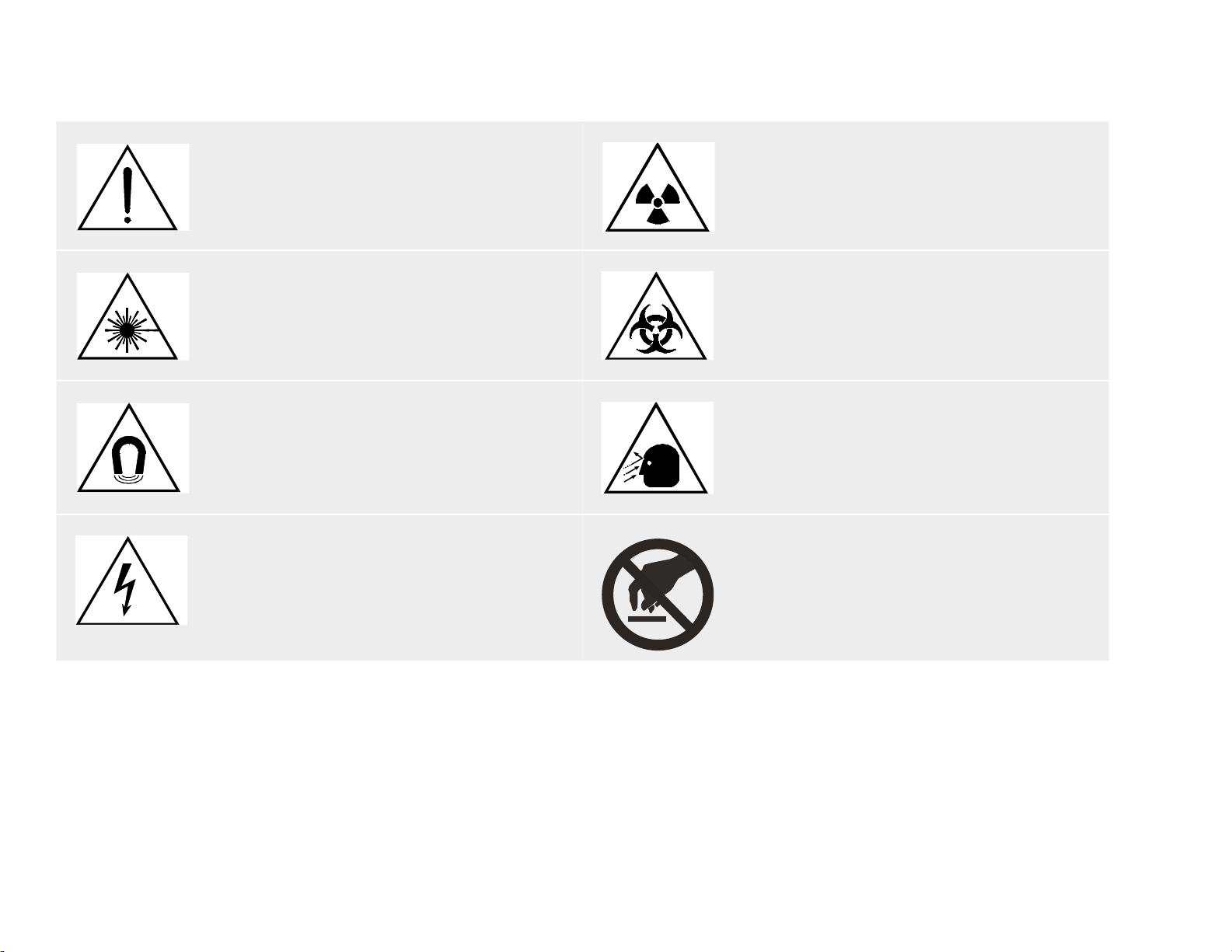
Symbol Descriptions
Attention symbol Radiation warning symbol
Laser warning symbol Biohazard warning symbol
Magnetism warning symbol Projectile warning symbol
Electrical warning symbol Do not touch
Page 4

Revision History
ECO # Revision Date Comments
H3002508 A July 2009 New Release
E-007395 B May 2010
E-130676 C July 2020 Updated NOTE on page 12
This document was prepared by the CT/NM Service Innovation.
For any additions, corrections, or suggestions, contact your next level of support.
Modified Performance Test Criteria
Matrix on page 2
Page 5

Safety Information
To the User of This Manual
The user of this manual is directed to read and carefully review the instructions, warnings and cautions contained herein prior to beginning installation or service
activities. While you may have previously installed or serviced equipment similar to that described in this manual, changes in design, manufacture or procedure
may have occurred which significantly affect the present installation or
Installation and Environment
Except for installations requiring certification by the manufacturer per federal standards, see that a radiation protection survey is made by a qualified expert in
accordance with NCRP 102, section 7, as revised or replaced in the future. Perform a survey after every change in equipment, workload, or operating conditions
which might significantly increase the probability of persons receiv
Diagnostic Imaging Systems - Mechanical-electrical Warning
All of the moveable assemblies and parts of this equipment should be operated with care and routinely inspected in accordance with the manufacturer’s
recommendations contained in the equipment manuals.
Only properly trained and qualified personnel should be permitted access to any internal parts. Live electrical terminals are deadly; be sure line disconnects are
opened and other appropriate precautions are taken before opening access doors, removing enclosure panels, or attaching accessories.
Do not under any circumstances, remove the flexible high tension cables from the x-ray tube housing or high tension generator and/or the access covers from the
generator until the main and auxiliary power supplies have been disconnected. Failure to comply with the above may result in serious or fatal bodily injuries to the
operator or thos
e in the area.
Electrical-grounding Instructions
The equipment must be grounded to an earth ground by a separate conductor. The neutral side of the line is not to be considered the earth ground. On equipment
provided with a line cord, the equipment must be connected to properly grounded, three-pin receptacle. Do not use a three-to-two pin adapter.
service.
ing more than the maximum permissible dose equivalent.
Diagnostic Imaging Systems - Radiation Warning
X-ray and Gamma-rays are dangerous to both operator and others in the vicinity unless established safe exposure procedures are strictly observed.
The useful and scattered beams can produce serious or fatal bodily injuries to any persons in the surrounding area if used by an unskilled operator. Adequate
precautions must always be taken to avoid exposure to the useful beam, as well as to leakage radiation from within the source housing or to scattered radiation
resulting from the passage of radiation through matter.
Those au
established safe exposure factors and procedures described in publications, such as: Subchapter J of Title 21 of the Code of Federal Regulations, "Diagnostic X-ray
Systems and Their Major Components", and the national council on radiation protection (NC
Up To 10 Mev-equipment Design and Use", as revised or replaced in the future.
Those responsible for planning of x-ray and gamma-ray equipment installations must be thoroughly familiar and comply completely with NCRP no. 49, "Structural
Shielding Design and Evaluation For Medical Of X-rays and Gamma-rays of Energies Up to 10 Mev", as revised and replaced in the future. Failure to observe these
warnings may cause serious or fatal bodily injuries to the operator or those in the area.
Add additional safety information as needed
thorized to operate, participate in or supervise the operation of the equipment must be thoroughly familiar and comply completely with the current
RP) no. 102, "Medical X-ray And Gamma-ray Protection For Energies
Page 6

MX 16-slice Performance Test Instructions Revision C
Contents
MX 16-slice Performance Manual .................................................................................................... 1
Introduction ............................................................................................................................................................ 1
Scope................................................................................................................................................................ 1
Overview ................................................................................................................................................................1
Equipment Required .........................................................................................................................................2
Performance Test Criteria Matrix...................................................................................................................... 2
Safety .....................................................................................................................................................................4
Prerequisites for Performance Testing................................................................................................................... 5
Automatic Tests ..................................................................................................................................................... 6
Position the System Test Phantom................................................................................................................... 6
Start the Automatic Test ...................................................................................................................................7
Automatic Performance Test ............................................................................................................................8
Before Beginning the Automatic Performance Test ....................................................................................8
Automatic Acceptance Test ............................................................................................................................14
Automatic Constancy Test.............................................................................................................................. 17
Automatic QA Test.......................................................................................................................................... 18
Appendix A: System Test Phantom ............................................................................................... 20
4550 193 03381 © 2020 Koninlijke Philips N.V All Rights Reserved CSIP Level 1 VI
Warning: This page contains copyrighted materials that are confidential and/or proprietary. Any release or distribution of this material, without permission, is a violation of law.
Page 7

MX 16-slice Performance Test Instructions
MX 16-slice Performance Manual
Introduction
This document provides system performance tests, test methods, and performance specifications for the MX 16-slice
System. Personnel using this document and performing these tests are expected to be familiar with CT system test
methods and the operation of the MX 16-sliceSystem. A MX 16-slice System meeting these performance specifications
is a necessary but not sufficient condition for acceptable system performance and acceptable image quality for system
shipment to customers and subsequent clinical use.
Scope
This document applies to all completely assembled and fully calibrated MX 16-slice CT Systems.
Overview
MX 16-slice Performance
The purpose of the Performance, Constancy, Acceptance and QA tests are as follows:
• Performance Test
Run this test after major component replacement such as, X-ray tube or DAS. This tests the general image quality
of the scanner.
• Acceptance Test
The Acceptance test is run in the field for the newly installed scanner or if major changes were made in the scanner
version and/or scanner hardware. The result obtained during the Acceptance test is the base line for the next
Constancy test.
• Constancy Test
The Constancy test is run during Planned Maintenance or component replacement. Constancy measures the
performance and stability of the system relative to the results received in the Acceptance test.
• QA Test
The QA test runs scans to compare the CT numberm Uniformity, and Noise of the scan wiht the allowed tollerance.
4550 193 03381 © 2020 Koninlijke Philips N.V All Rights Reserved CSIP Level 1 1
Warning: This page contains copyrighted materials that are confidential and/or proprietary. Any release or distribution of this material, without permission, is a violation of law.
Page 8
MX 16-slice Performance Test Instructions
Equipment Required
System Test Phantom 455012001021
Performance Test Criteria Matrix
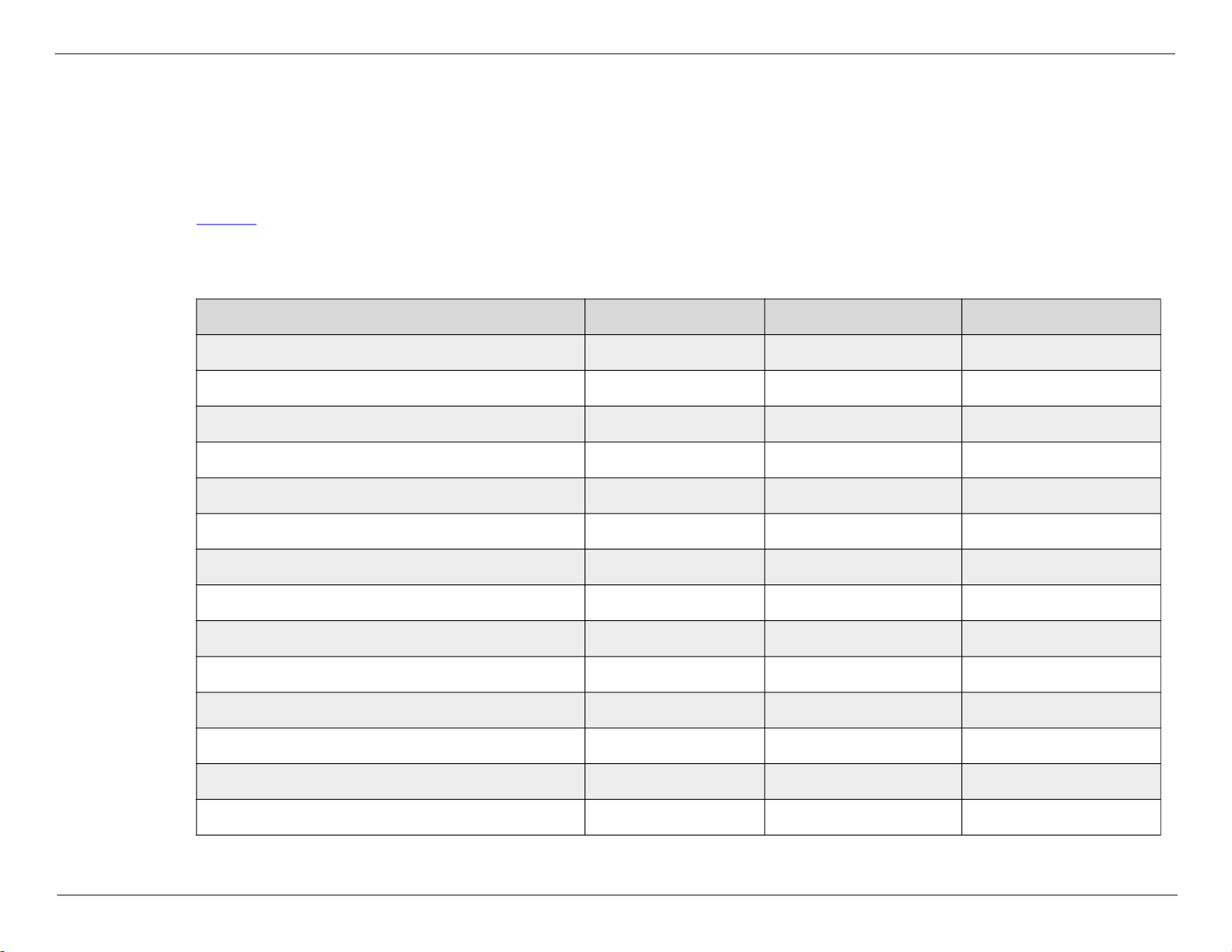
Table 1 lists the Performance tests required when performing the listed procedures.
Follow the instructions in this manual for the performance tests indicated in the table.
Procedure Performance Constancy Acceptance
MX 16-slice Performance
Table 1:
New system Installation
Site System Installation
X-ray tube replacement
HV Generator replacement
Ref. Detector replacement
A-Plane Replacement
Z Position Detector Board Replacement
Central six ADM Replacement
Single ADM replacement
Compensator Replacement
Reference Converter Board Replacement
DMS Replacement
Slice Thickness Detection Board Replacement
Y
Y Y
Y Y
Y
Y
Y Y
Y
Y Y
Y Y
Y Y
Y
Y Y
Y
Planned Maintenance
4550 193 03381 © 2020 Koninlijke Philips N.V All Rights Reserved CSIP Level 1 2
Warning: This page contains copyrighted materials that are confidential and/or proprietary. Any release or distribution of this material, without permission, is a violation of law.
Y Y
Page 9

MX 16-slice Performance Test Instructions
NOTE If the Constancy test fails, repeat the Acceptance test.
MX 16-slice Performance
4550 193 03381 © 2020 Koninlijke Philips N.V All Rights Reserved CSIP Level 1 3
Warning: This page contains copyrighted materials that are confidential and/or proprietary. Any release or distribution of this material, without permission, is a violation of law.
Page 10
MX 16-slice Performance Test Instructions
!
!
!
MX 16-slice Performance
Safety
WARNING collision hazard! when mounting the phantom make sure that it is positioned so that it
will not come in contact with the gantry covers or the rotor.
WARNING Close all Gantry covers before performing tests. Check that the temperature regulation
of the gantry and the DMS function properly. wait for the temperature to stabilize
within ±2 ℃ .
CAUTION Ensure that the phantom is completely vertical (Tilt = 0) before performing any calibration or
performance tests; tilt or misalignment of the phantom may result in inaccurate calibration and
performance tests.
4550 193 03381 © 2020 Koninlijke Philips N.V All Rights Reserved CSIP Level 1 4
Warning: This page contains copyrighted materials that are confidential and/or proprietary. Any release or distribution of this material, without permission, is a violation of law.
Page 11

MX 16-slice Performance Test Instructions
Prerequisites for Performance Testing
1. All operating software has been installed and Auto-Calibration has been successfully completed.
2. The system is fully functional with all hardware and software calibrations complete and performs according to
specification. All covers must be in place and securely attached. All other safety covers or switches must be in their
normal operating positions or states unless specifically changed by a test procedure.
MX 16-slice Performance
3. The X-ray tube must be warmed up to a nominal tube heat (20%) be
fore starting the test and all air calibrations
must be current.
4. The Gantry / Detector cooling system must be fully functional, and must maintain normal and stable temperatures.
The normal DMS (Data Measurement System) operating temperature is 32 ±2°C. It is important to maintain
temperature stability within ±2°C between calibration and image performance testing in order for the test results to
be valid.
4550 193 03381 © 2020 Koninlijke Philips N.V All Rights Reserved CSIP Level 1 5
Warning: This page contains copyrighted materials that are confidential and/or proprietary. Any release or distribution of this material, without permission, is a violation of law.
Page 12
MX 16-slice Performance Test Instructions
Automatic Tests
Position the System Test Phantom
To launch the Automatic Tests described in this manual, position the System Phantom according to the following
procedure.
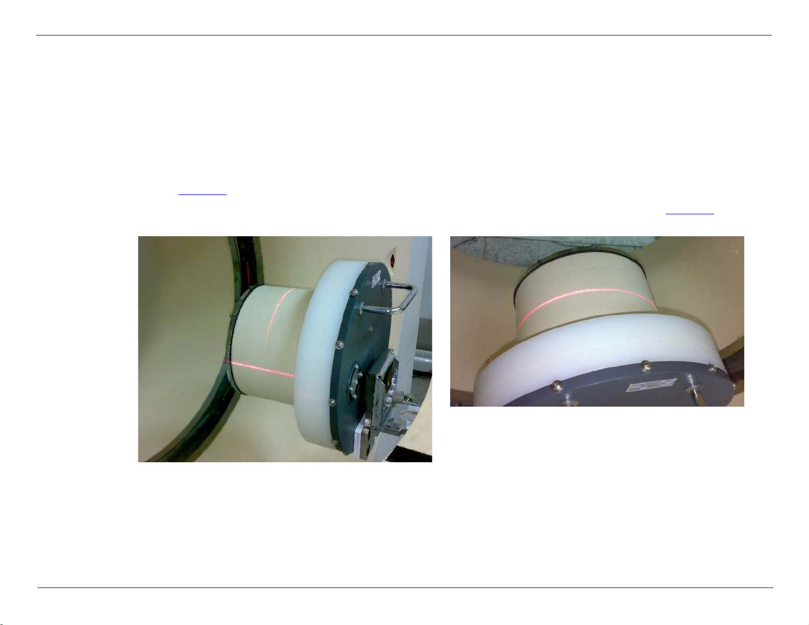
1. Position the System Phantom at the head of the Patient Table using the Phantom Holder.
2. Manually control the height of the Patient Table so that the outside laser marker is set to the center of the Phantom
(see Figure 1
).
MX 16-slice Performance
3. Manually move the Patient Table Top so that the Inner Laser Marker set to the water layer (see Figure 2
Figure 2: Upside
Figure 1: Lateral Side
).
4550 193 03381 © 2020 Koninlijke Philips N.V All Rights Reserved CSIP Level 1 6
Warning: This page contains copyrighted materials that are confidential and/or proprietary. Any release or distribution of this material, without permission, is a violation of law.
Page 13
MX 16-slice Performance Test Instructions
Start the Automatic Test
1. Insert the IST key, and log On the IST.
2. Double click the MX 16-slice icon on desktop, and log On
as ctsoft(ctsoft).
3. Warm up the X-Tube to 20%.
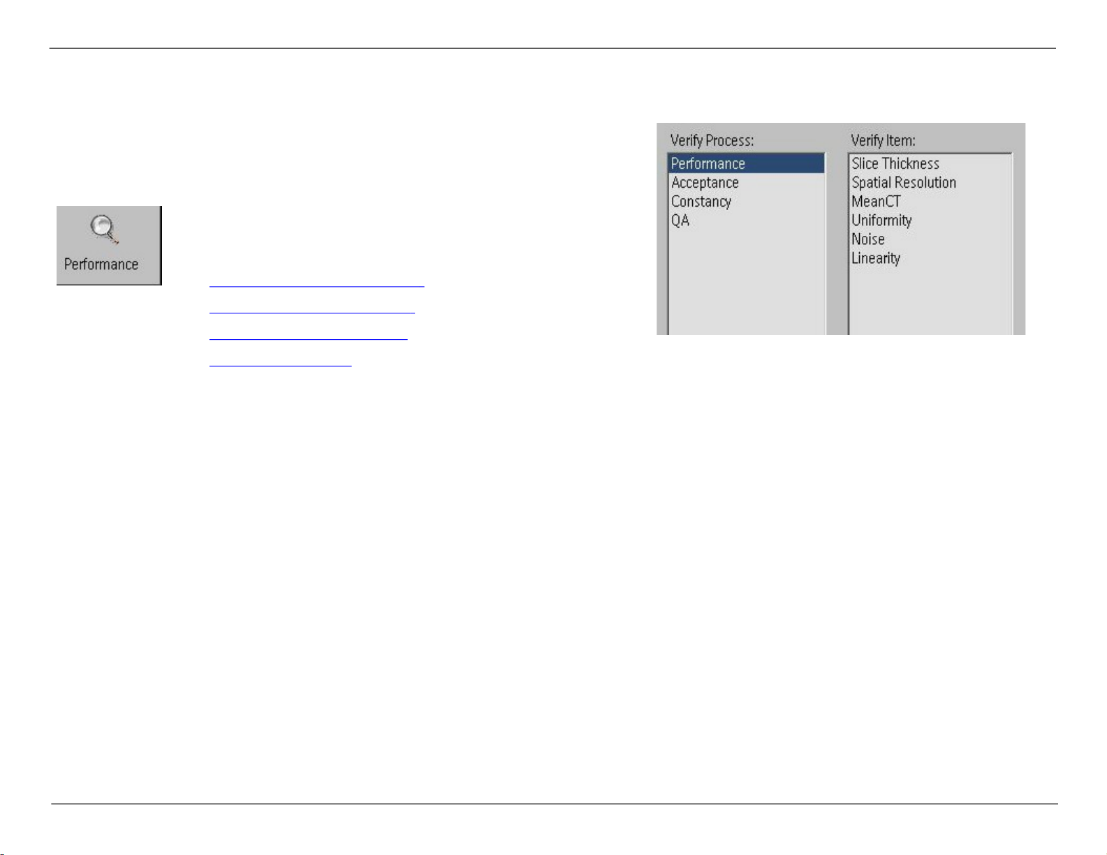
4. From the main menu, click Service, select the Advanced
Service tab, select Performance, and perform the
Automatic Tests in the following order:
• Automatic Performance Test on page 8
• Automatic Acceptance Test on page 14
• Automatic Constancy Test on page 17
• Automatic QA Test on page 18
NOTE During performance tests, verify that the images are free of rings and other artifacts.
MX 16-slice Performance
Figure 3: Automatic Tests Process
4550 193 03381 © 2020 Koninlijke Philips N.V All Rights Reserved CSIP Level 1 7
Warning: This page contains copyrighted materials that are confidential and/or proprietary. Any release or distribution of this material, without permission, is a violation of law.
Page 14

MX 16-slice Performance Test Instructions
Automatic Performance Test
The Automatic Performance Test runs scans of different types to check the performance of the system, the full test
performs 16 scans in different modes and takes approximately 15 minuntes to complete.
Before Beginning the Automatic Performance Test
• The Automatic Performance tests scans the images automatically but does not check the individual scans for
rings, bands and artifacts; inspection of images MUST be performed by the FSE. No rings or bands are
allowed on the image. Use a window width of 100 for Head and 150 for Body, with the window centered on the
CT number of the material (e.g. 0 for Water).
• For all Scans: If a scan in any mode fails with comply to specified tolerances, repeat the scan manually using
the same parameters and verify that the results are correct. The SD and CT tolerance values may change
during the lifetime of the system.
NOTE If the error message” Tube Power Limit Exceeded” is displayed, wait until the tube cools down and try running the
scan again.
MX 16-slice Performance
4550 193 03381 © 2020 Koninlijke Philips N.V All Rights Reserved CSIP Level 1 8
Warning: This page contains copyrighted materials that are confidential and/or proprietary. Any release or distribution of this material, without permission, is a violation of law.
Page 15
MX 16-slice Performance Test Instructions
Run the Automatic Performance Test according to the
following procedure:
1. In Auto-performance dialog box, highlight
Performance (see Figure 3
Next.
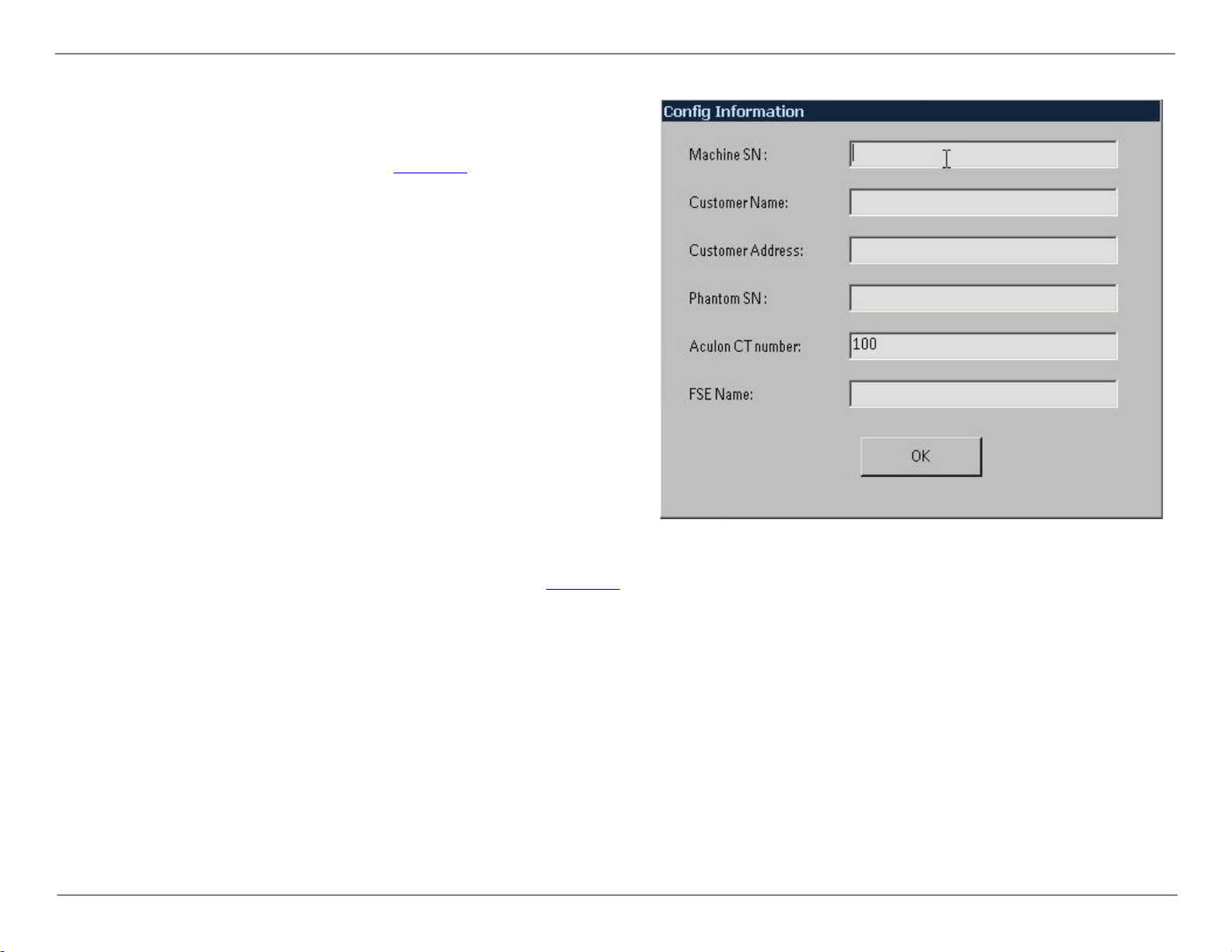
2. In the Config Information dialog box, enter the
required information.
• Machine SN
• Customer Name
• Customer Address
• Phantom SN
• Aculon CT Number
• FSE Name
NOTE The recommended Aculon CT
MX 16-slice Performance
on page 7), and click
Numer is 100.
3. Click OK.
Figure 4: Config Information
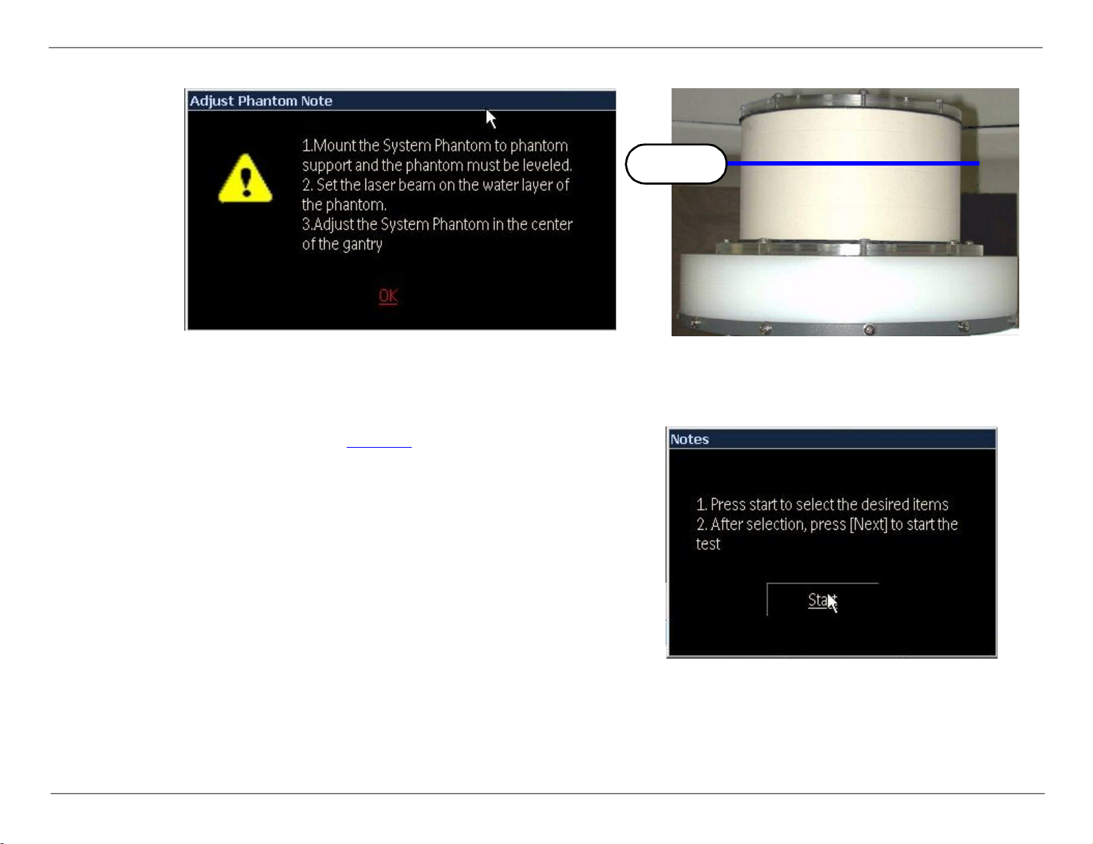
4. An Instructions dialog box opens (see Figure 5 on page 10). Follow the on-screen instructions to positon the
System Phantom, and once it is in position, click OK to continue.
a. Mount the System Phantom to the Phantom Support. The Phantom must be level.
b. Set the laser beam to the Water Layer of the Phantom.
c. Adjust the System Phantom in the center of the Gantry.
4550 193 03381 © 2020 Koninlijke Philips N.V All Rights Reserved CSIP Level 1 9
Warning: This page contains copyrighted materials that are confidential and/or proprietary. Any release or distribution of this material, without permission, is a violation of law.
Page 16
MX 16-slice Performance Test Instructions
MX 16-slice Performance
Water Layer
Figure 5: Position Phantom Instruction
Make
5. In the following dialog boxes click Start to select the
desired items (see Figure 7
on page 10).
6. Select the desired items and click Next to continue the
Performance test.
Figure 6: Water Layer (to be updated)
Figure 7: Select the desired items
4550 193 03381 © 2020 Koninlijke Philips N.V All Rights Reserved CSIP Level 1 10
Warning: This page contains copyrighted materials that are confidential and/or proprietary. Any release or distribution of this material, without permission, is a violation of law.
Page 17
MX 16-slice Performance Test Instructions
MX 16-slice Performance
WARNING Make sure there is no one in scanner room, and the scanner room door is closed.
7. Click OK to continue.
8. The application scans the System Phantom and calculates the position of the System Phantom.
If the position is not accepted, the application provides instructions to adjust the position of the Phantom.
9. When the System Phantom position is accepted, the system will automatically start the Performance Test scan (see
Figure 8
on page 11).
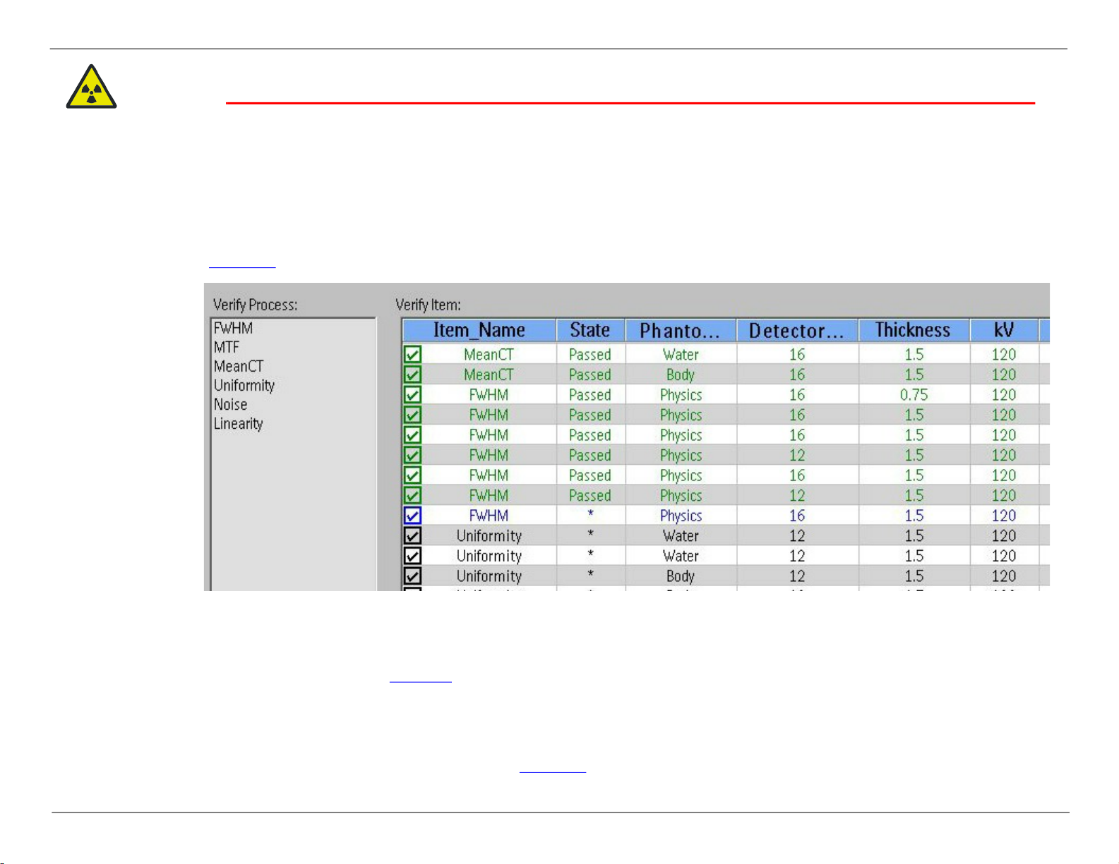
Figure 8: Verify Items
The test automatically runs a sequence of scans. The scans and scan parameters are listed in Verify Item area.
10. When the image quality of each item is found to comply with the required tolerances its State is recorded in green
as Passed as shown in Figure 8
on page 11. When the image quality of an item fails to comply with any required
tolerance its State is recorded in red as Failed.
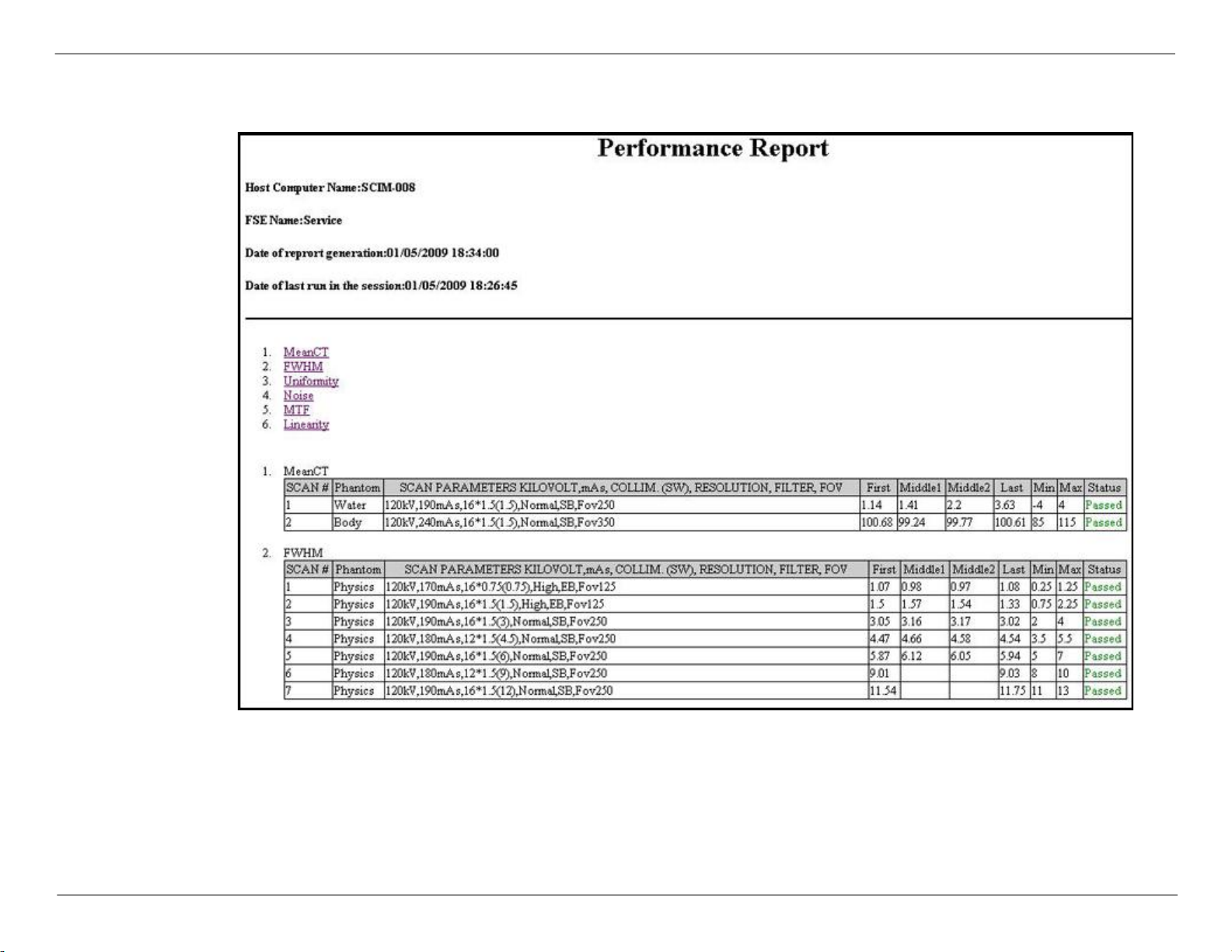
11. When the Auto-performance test is complete, an Auto-performance report is generated automatically and saved on
the disk.
12. Click Report to view the test results (see Figure 9
4550 193 03381 © 2020 Koninlijke Philips N.V All Rights Reserved CSIP Level 1 11
Warning: This page contains copyrighted materials that are confidential and/or proprietary. Any release or distribution of this material, without permission, is a violation of law.
on page 12).
Page 18
MX 16-slice Performance Test Instructions
NOTE If any of the sub-items failed during the Auto-performance test, repeat the same sub-item or perform it again
manually.
MX 16-slice Performance
Figure 9: Performance Report (Example)
4550 193 03381 © 2020 Koninlijke Philips N.V All Rights Reserved CSIP Level 1 12
Warning: This page contains copyrighted materials that are confidential and/or proprietary. Any release or distribution of this material, without permission, is a violation of law.
Page 19
MX 16-slice Performance Test Instructions
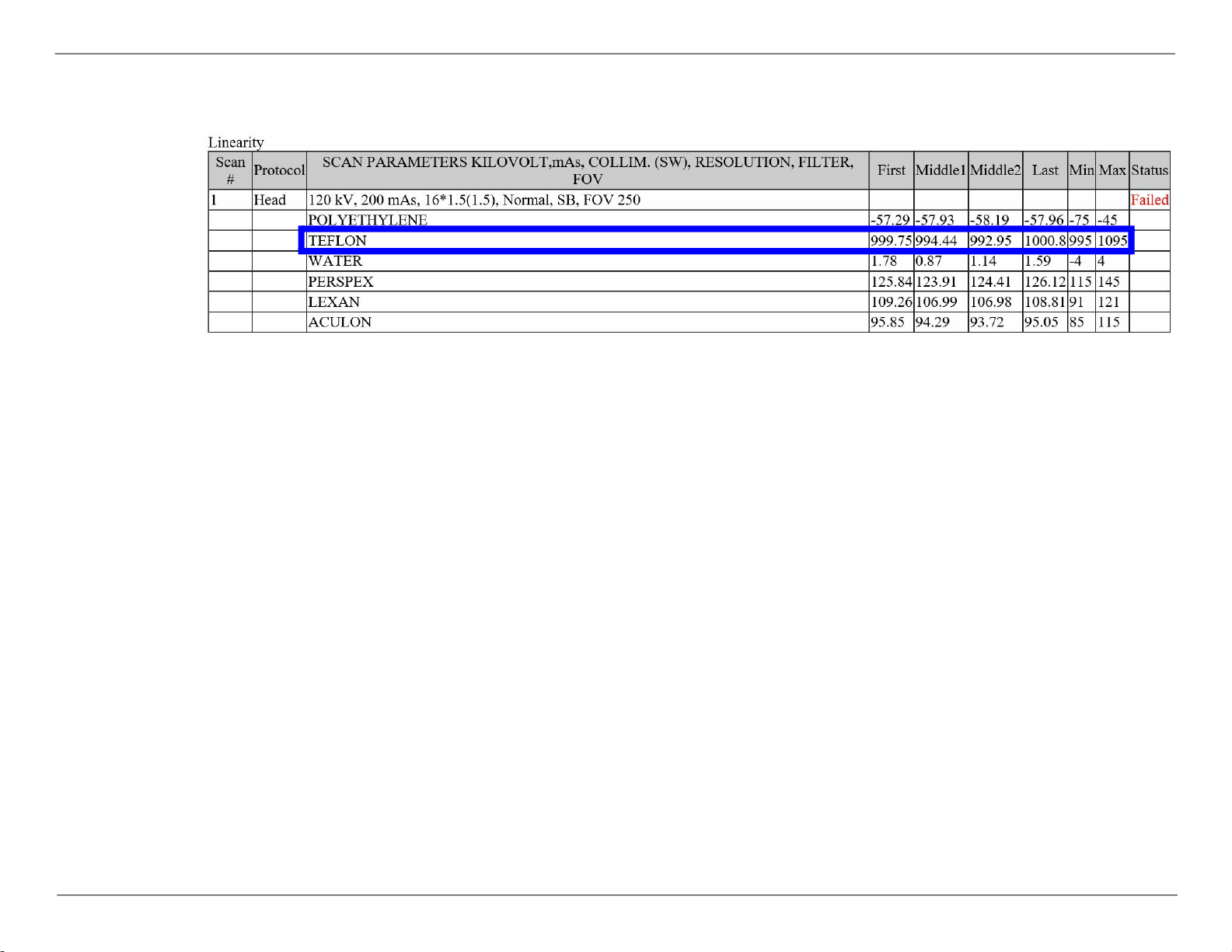
Exception: when any of the Teflon CT value failed during the Auto-performance test, please ignore if it is in the
range of 900-1100HU.
MX 16-slice Performance
Figure 10: Example
4550 193 03381 © 2020 Koninlijke Philips N.V All Rights Reserved CSIP Level 1 13
Warning: This page contains copyrighted materials that are confidential and/or proprietary. Any release or distribution of this material, without permission, is a violation of law.
Page 20
MX 16-slice Performance Test Instructions
Automatic Acceptance Test
Run the Automatic Acceptance Test according to the
following procedure:
1. In the Auto-performance dialog box, highlight
Acceptance (see Figure 3
Next.
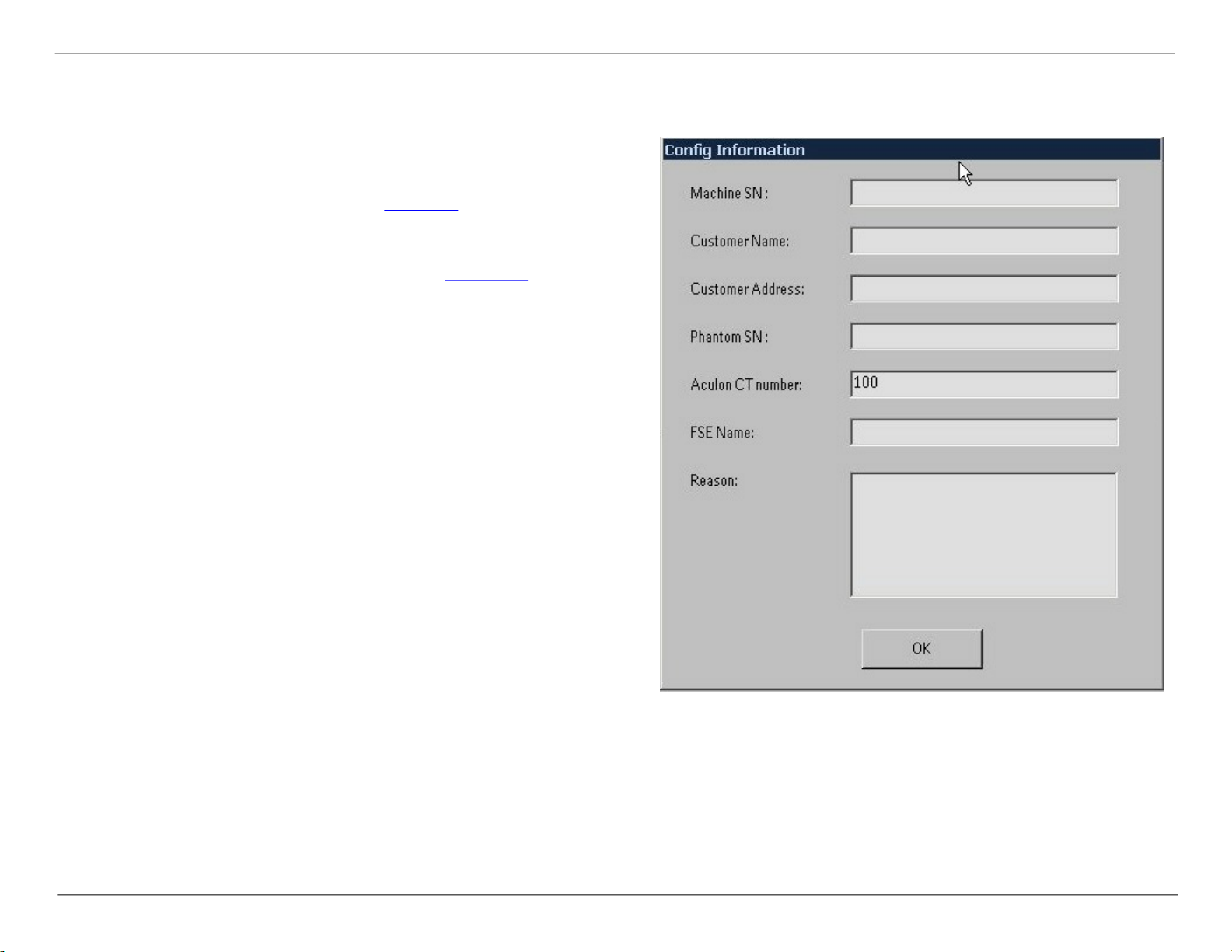
2. In the Config Information dialog box, enter the
required information (see Figure 11
• Machine SN
• Customer Name
• Customer Address
• Phantom SN
• Aculon CT Number
• FSE Name
• Reason
MX 16-slice Performance
on page 7), and click
on page 14).
NOTE The recommended Aculon CT
Numer is 100.
3. Click OK.
Figure 11: Config Information
4. An Instructions dialog box appears. Follow the on-screen instructions to positon the System Phantom, and once it is
in position, click OK to continue.
5. In the following window, click Start to select the desired items, and click Next to continue the Acceptance test.
4550 193 03381 © 2020 Koninlijke Philips N.V All Rights Reserved CSIP Level 1 14
Warning: This page contains copyrighted materials that are confidential and/or proprietary. Any release or distribution of this material, without permission, is a violation of law.
Page 21
MX 16-slice Performance Test Instructions
MX 16-slice Performance
WARNING Make sure no one is in the scanner room, and the scanner room door is closed.
6. Click OK to continue.
7. The application scans the System Phantom and calculates the position of the System Phantom.
If the position is not accepted, the application will provide instructions for adjusting position of the Phantom.
8. When the System Phantom position is accepted, the system will automatically start the Acceptance Test scan.
The test automatically runs a sequence of scans and the scans and parameters are listed in Verify Item area.
9. When the image quality of each item is found to comply with the required tolerances its State is recorded in green
as Passed. When the image quality of an item fails to comply with any required tolerance its State is recorded in red
as Failed.
10. When the Auto-acceptance test has completed, an Auto-acceptance report is generated automatically and saved.
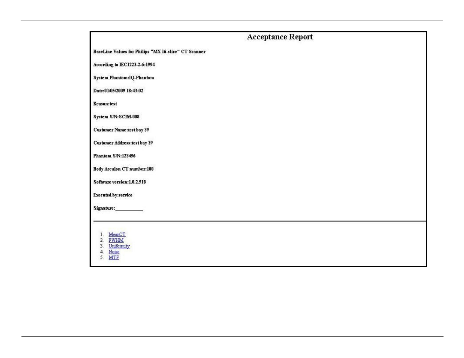
11. Click Report to view the test results (see Figure 12
on page 16).
NOTE If any of the sub-items failed during the auto-Acceptance test, repeat the same sub-item or perform it again
manually.
12. When all the items passed and the measurements are within the required ranges, a baseline is automatically
saved.
4550 193 03381 © 2020 Koninlijke Philips N.V All Rights Reserved CSIP Level 1 15
Warning: This page contains copyrighted materials that are confidential and/or proprietary. Any release or distribution of this material, without permission, is a violation of law.
Page 22
MX 16-slice Performance Test Instructions
MX 16-slice Performance
Figure 12: Acceptance Report (Example)
4550 193 03381 © 2020 Koninlijke Philips N.V All Rights Reserved CSIP Level 1 16
Warning: This page contains copyrighted materials that are confidential and/or proprietary. Any release or distribution of this material, without permission, is a violation of law.
Page 23
MX 16-slice Performance Test Instructions
Automatic Constancy Test
Run the Automatic Constancy Test according to the following procedure:
MX 16-slice Performance
1. In the Auto-performance dialog box, highlight Constancy (see Figure 3
2. Follow Step 2
on page 14 to Step 9 on page 15 of the Automatic Acceptance Test on page 14.
on page 7), and click Next.
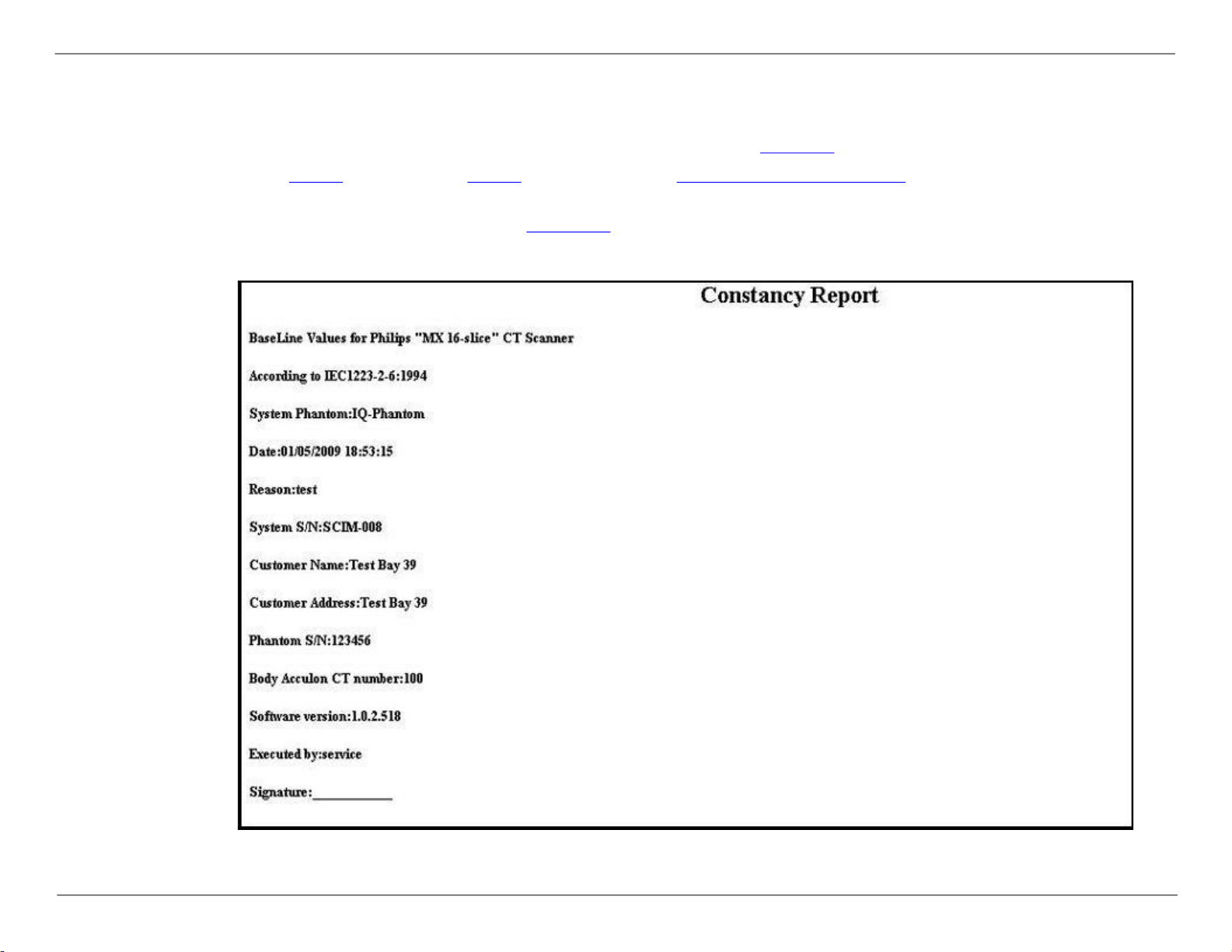
3. When the Auto-constancy test is complete, an Auto-constancy report is generated automatically and saved. Click
Report to view the test results (see Figure 13
on page 17).
NOTE If any of the sub-items failed during auto-Constancy test, repeat the same sub-item or perform it again manually.
Figure 13: Constancy Report (Example)
4550 193 03381 © 2020 Koninlijke Philips N.V All Rights Reserved CSIP Level 1 17
Warning: This page contains copyrighted materials that are confidential and/or proprietary. Any release or distribution of this material, without permission, is a violation of law.
Page 24

MX 16-slice Performance Test Instructions
Automatic QA Test
Run the Automatic QA Test according to the following procedure:
MX 16-slice Performance
1. In the Auto-performance dialog box, highlight QA (see Figure 3
2. Follow Step 2
on page 14 to Step 9 on page 15 of the Automatic Acceptance Test on page 14.
on page 7), and click Next.
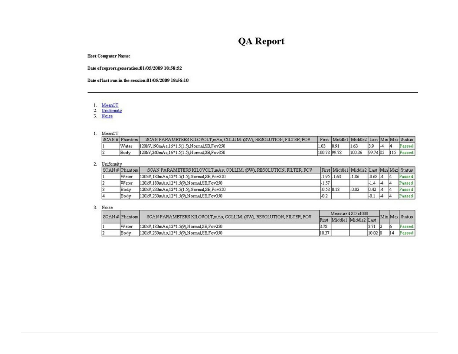
3. When the QA Test has completed, a QA Test report is generated automatically and saved. Click Report to view the
test results (see Figure 13
on page 17).
NOTE If any of the sub-items failed during QA test, repeat the same sub-item or perform it again manually.
4550 193 03381 © 2020 Koninlijke Philips N.V All Rights Reserved CSIP Level 1 18
Warning: This page contains copyrighted materials that are confidential and/or proprietary. Any release or distribution of this material, without permission, is a violation of law.
Page 25
MX 16-slice Performance Test Instructions
MX 16-slice Performance
Figure 14: QA Test Report
4550 193 03381 © 2020 Koninlijke Philips N.V All Rights Reserved CSIP Level 1 19
Warning: This page contains copyrighted materials that are confidential and/or proprietary. Any release or distribution of this material, without permission, is a violation of law.
Page 26

MX 16-slice Performance Test Instructions
Appendix A: System Test Phantom
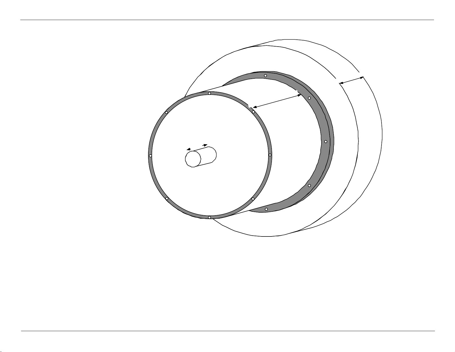
The test phantom used for the majority of these tests is the System Performance Phantom. This phantom is supplied as
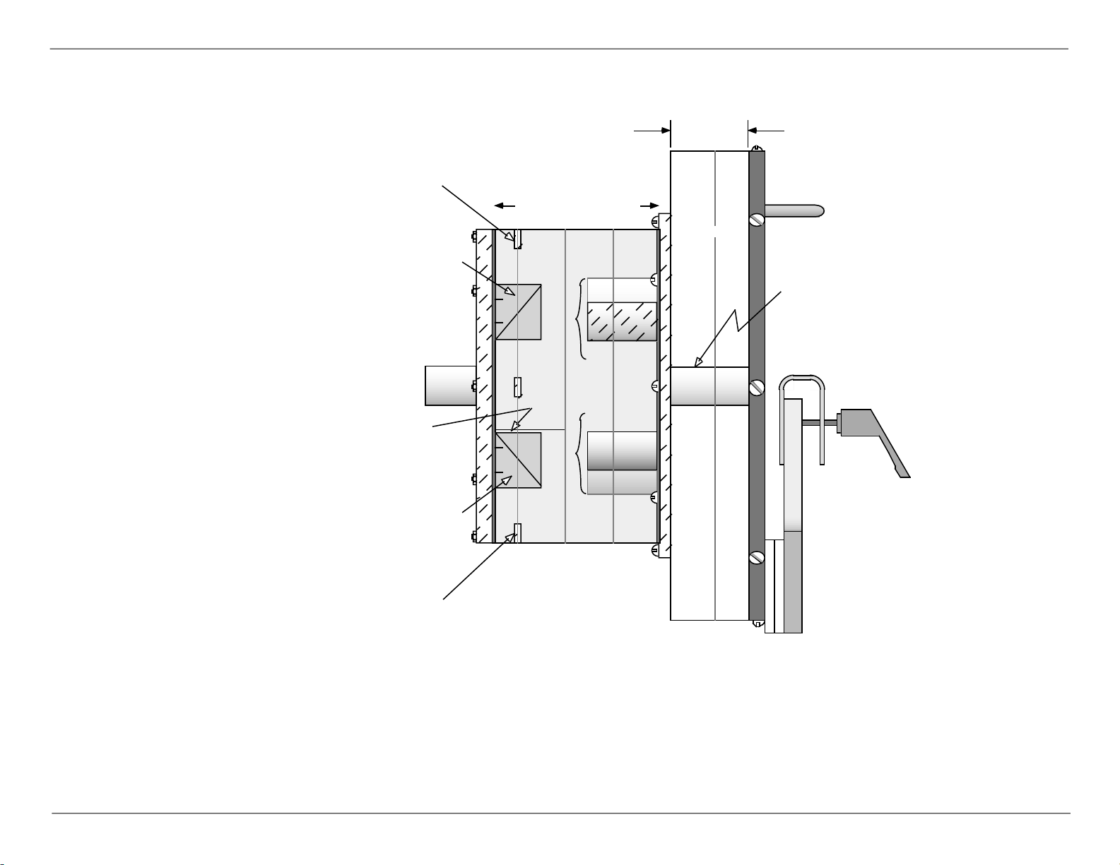
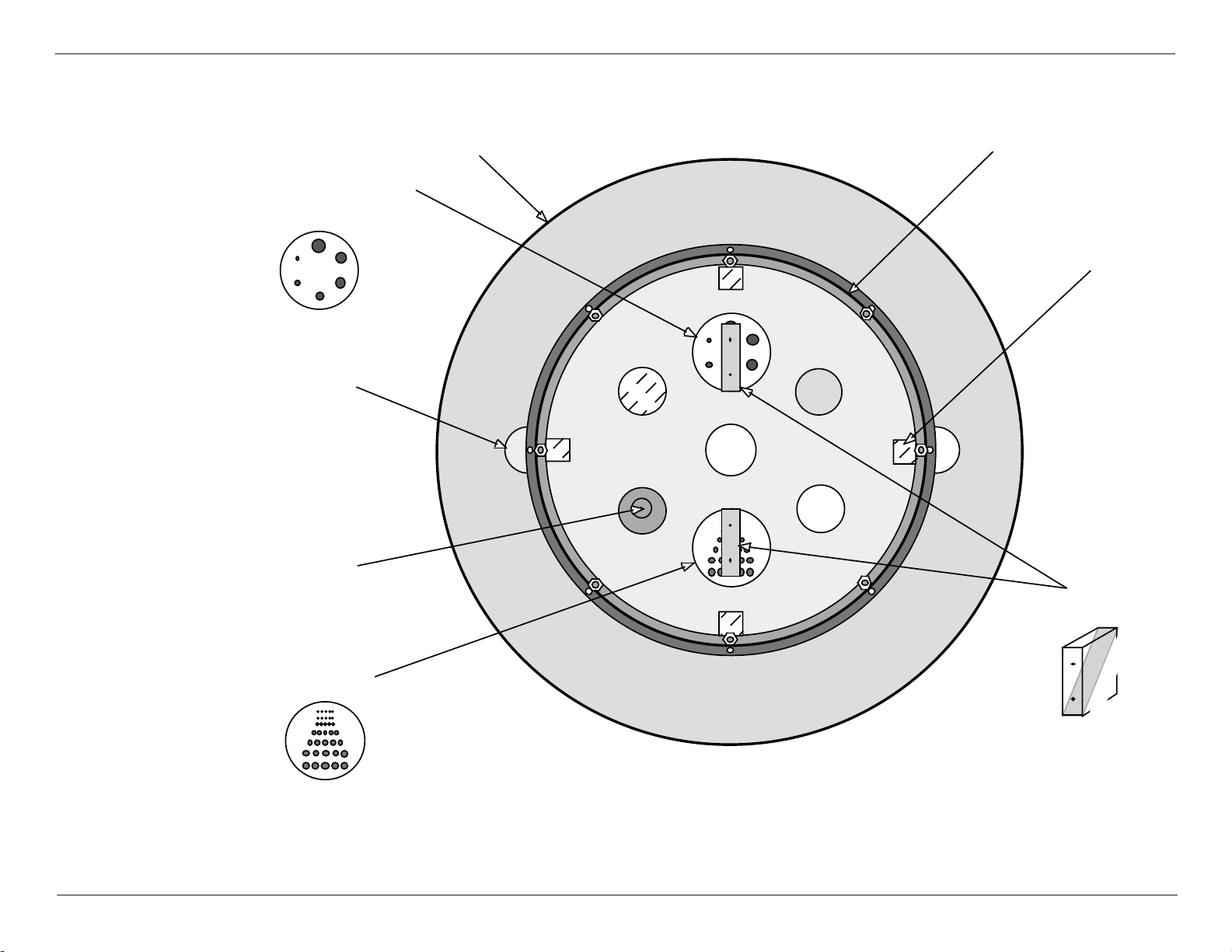
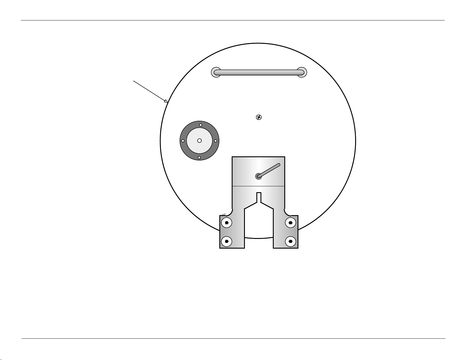
part of every MX 16-slice system. The phantom consists of a combined Head and Body Phantom. The Head Phantom
is a 200 mm diameter PVC shell filled with distilled water. The Head Phantom has three sections (see detailed
description of the system phantom in Figure 15
1. The physics layer is used for impulse response and tomographic section thickness (slice width) measurements.
2. The water layer is used to measure uniformity and noise.
3. The Multi–Pin Layer is used for low contrast scale check.
The Body Phantom part of this phantom consists of a water hole (0 ±10 CT) and air (1000 ±10 CT).
System Test Phantom
on page 21–Figure 18 on page 24.
4550 193 03381 © 2020 Koninlijke Philips N.V All Rights Reserved CSIP Level 1 20
Warning: This page contains copyrighted materials that are confidential and/or proprietary. Any release or distribution of this material, without permission, is a violation of law.
Page 27
MX 16-slice Performance Test Instructions
Large Field (300 mm) Section
Small Field (250 mm) Section
A
l
u
m
i
n
u
m
(
S
l
i
c
e
W
i
d
t
h
)
L
a
y
e
r
W
a
t
e
r
L
a
y
e
r
M
u
l
t
i
p
i
n
L
a
y
e
r
116 mm
60 mm
Centering
Pin
(25 mm
OD)
33 mm
Oblique View
System Test Phantom
Figure 15:
4550 193 03381 © 2020 Koninlijke Philips N.V All Rights Reserved CSIP Level 1 21
Warning: This page contains copyrighted materials that are confidential and/or proprietary. Any release or distribution of this material, without permission, is a violation of law.
Page 28
MX 16-slice Performance Test Instructions
Aluminum (Slice Width) Layer
Water Layer
Multipin Layer
Small Field (250 mm) Section
is filled with water
Large Field (300 mm) Section
is filled with Aculon
Centering
Pin
Mounting
Clamp
Handle
Lexan
pin
Ramp
Locator
Spatial Phantom
Low Contrast Phantom
Slice Width Ramp
Slice Width Ramp
Teflon pin
Ramp
Locator
Point Spread Function Phantom
(0.18 mm copper wire)
Water pin is
behind the
Teflon pin
Aculon
Perspex
pin
Perspex
pin
Left Side View
System Test Phantom
Figure 16:
4550 193 03381 © 2020 Koninlijke Philips N.V All Rights Reserved CSIP Level 1 22
Warning: This page contains copyrighted materials that are confidential and/or proprietary. Any release or distribution of this material, without permission, is a violation of law.
Page 29
MX 16-slice Performance Test Instructions
Large Field (300 mm OD) Section
Small Field (200 mm OD) Section
Spatial Phantom,
Perspex (|130 ± 15) with Lexan pins
Low Contrast Phantom,
Aculon (|100 ± 15) with Lexan pins
6 mm
3 mm
5 mm
2 mm
7 mm
4 mm
Aluminum
Slice
Width
Ramp
Polyethelyene
(|-60 ± 15)
Perspex
(|130 ± 15)
Teflon
(|950 ± 50)
Lexan
(|110 ± 15)
Centering
pin
Point Spread Function Phantom
(0.18 mm copper wire)
aluminum strip at 45° to horizontal
Note:
Aculon = nylon
Perspex = acrylic
R
P
1 of 4 Ramp
Locators
Teflon
in Large Field Sec
(|950 ± 50)
Water
in Large Field Section
(0 ± 10)
System Test Phantom
Figure 17:
4550 193 03381 © 2020 Koninlijke Philips N.V All Rights Reserved CSIP Level 1 23
Warning: This page contains copyrighted materials that are confidential and/or proprietary. Any release or distribution of this material, without permission, is a violation of law.
Page 30
MX 16-slice Performance Test Instructions
Handle
Mounting Clamp
Water Fill
Full Field (300 mm OD) Section
Front View
System Test Phantom
Figure 18:
4550 193 03381 © 2020 Koninlijke Philips N.V All Rights Reserved CSIP Level 1 24
Warning: This page contains copyrighted materials that are confidential and/or proprietary. Any release or distribution of this material, without permission, is a violation of law.
Page 31

MX 16-slice Performance Test Instructions
Table 2:
Pin Number Description
1 Nylon (Aculon) body with six smaller Lexan pins of 3 mm, 4 mm, 5 mm, 6 mm, 7 mm and 8 mm diameter.
2 Polyethylene
3 Teflon
4 Perspex with seven rows of holes of different diameters. Each row has five equidistant holes of the same
diameter, as follows:
Row 1 1.00 mm holes, 2.00 mm apart
Row 2 1.25 mm holes, 2.50 mm apart
Row 3 1.50 mm holes, 3.00 mm apart
Row 4 1.75 mm holes, 3.50 mm apart
System Test Phantom
Row 5 2.00 mm holes, 4.00 mm apart
Row 6 2.50 mm holes, 5.00 mm apart
Row 7 3.00 mm holes, 6.00 mm apart
5 Lexan
6 Perspex
Region 7 PVC (shell)
4550 193 03381 © 2020 Koninlijke Philips N.V All Rights Reserved CSIP Level 1 25
Warning: This page contains copyrighted materials that are confidential and/or proprietary. Any release or distribution of this material, without permission, is a violation of law.
 Loading...