

Philips MX 8000 User manual

PHILIPS MEDICAL SYSTEMS
Mx8000 Systems
Installation Manual
491-7181-3501 November 2002 Revision A
ALL PAGES OF THIS DOCUMENT CONTAIN PROPRIETARY AND CONFIDENTIAL INFORMATION OF PHILIPS MEDICAL SYSTEMS
(CLEVELAND), INC. THE DOCUMENTS ARE INTENDED FOR CURRENT PHILIPS MEDICAL SYSTEMS’ PERSONNEL OR ARE LICENSED TO
PHILIPS MEDICAL SYSTEMS’ CUSTOMER FOR USE BY THE CUSTOMER'S IN-HOUSE SERVICE EMPLOYEE ON EQUIPMENT LOCATED AT THE
CUSTOMER'S DESIGNATED SITE. COPYING, DISCLOSURE TO OTHERS OR OTHER USE IS PROHIBITED WITHOUT THE EXPRESS WRITTEN
AUTHORIZATION OF PHILIPS MEDICAL SYSTEMS’ LAW DEPARTMENT. REPORT VIOLATIONS OF THESE REQUIREMENTS TO PHILIPS
MEDICAL SYSTEMS’ LAW DEPARTMENT, HIGHLAND HEIGHTS, OHIO
Service Publications, Philips Medical Systems (Cleveland) Inc., Highland Hts., OH
© 2002 All rights reserved under the copyright laws of the United States
44143

2002
Philips Medical Systems (Cleveland), Inc. Highland Hts., OH 44143
All rights reserved under the copyright laws of the United States.
This document prepared by the PMSTL Service Innovations Department.
For any additions, corrections, or suggestions, contact:
PMSTL Customer Support Department
Email: pmstl.support@cle.philips.com

491-7181-3501
Revision A, November 2002
Mx8000 Systems
Installation Manual
Revision History
E.C.O # REV DATE DESCRIPTION PAGES PREPARED BY
E13000113 0 Dec. 2001 New Release All R. Yurovitsky S. Sahar
D13020006 A Nov. 2002
CDRH tests
removed
Chap 11 Zeev Gertz S. Sahar
APPROVED
BY
Links to Physics
and CDRH Files
Chap 10
added

491-7181-3501
Revision A, November 2002
Mx8000 Systems
Installation Manual
NOTICE
THE INFORMATION CONTAINED IN THIS MANUAL CONFORMS WITH THE CONFIGURATION OF THE EQUIPMENT AS OF THE
DATE OF MANUFACTURE. REVISIONS TO THE EQUIPMENT SUBSEQUENT TO THE DATE OF MANUFACTURE WILL BE ADDRESSED
IN SERVICE UPDATES DISTRIBUTED TO PHILIPS MEDICAL SYSTEMS (CLEVELAND), INC. TECHNICAL SERVICE ORGANIZATION.
TO THE USER OF THIS MANUAL
THE USER OF THIS MANUAL IS DIRECTED TO READ AND CAREFULLY REVIEW THE INSTRUCTIONS, WARNINGS AND
CAUTIONS CONTAINED HEREIN PRIOR TO BEGINNING INSTALLATION OR SERVICE ACTIVITIES. WHILE YOU MAY HAVE
PREVIOUSLY INSTALLED OR SERVICED EQUIPMENT SIMILAR TO THAT DESCRIBED IN THIS MANUAL, CHANGES IN DESIGN,
MANUFACTURE OR PROCEDURE MAY HAVE OCCURRED WHICH SIGNIFICANTLY AFFECT THE PRESENT INSTALLATION OR
SERVICE.
THE INSTALLATION AND SERVICE OF EQUIPMENT DESCRIBED HEREIN IS TO BE PREFORMED BY AUTHORIZED, QUALIFIED
PHILIPS MEDICAL SYSTEM PERSONNEL. ASSEMBLERS AND OTHER PERSONNEL NOT EMPLOYED BY NOR DIRECTLY AFFILIATED
WITH PHILIPS MEDICAL SYSTEMS TECHNICAL SERVICES ARE DIRECTED TO CONTACT THE LOCAL PHILIPS MEDICAL SYSTEMS
OFFICE BEFORE ATTEMPTING INSTALLATION OR SERVICE PROCEDURES.
INSTALLATION AND ENVIRONMENT
EXCEPT FOR INSTALLATIONS REQUIRING CERTIFICATION BY THE MANUFACTURER PER FEDERAL STANDARDS, SEE THAT A
RADIATION PROTECTION SURVEY IS MADE BY A QUALIFIED EXPERT IN ACCORDANCE WITH NCRP 102, SECTION 7, AS
REVISED OR REPLACED IN THE FUTURE. PERFORM A SURVEY AFTER EVERY CHANGE IN EQUIPMENT, WORKLOAD, OR
OPERATING CONDITIONS WHICH MIGHT SIGNIFICANTLY INCREASE THE PROBABILITY OF PERSONS RECEIVING MORE THAN
THE MAXIMUM PERMISSIBLE DOSE EQUIVALENT
Diagnostic Imaging Systems - MECHANICAL-ELECTRICAL WARNING
ALL OF THE MOVEABLE ASSEMBLIES AND PARTS OF THIS EQUIPMENT SHOULD BE OPERATED WITH CARE AND ROUTINELY
INSPECTED IN ACCORDANCE WITH THE MANUFACTURER'S RECOMMENDATIONS CONTAINED IN THE EQUIPMENT MANUALS.
ONLY PROPERLY TRAINED AND QUALIFIED PERSONNEL SHOULD BE PERMITTED ACCESS TO ANY INTERNAL PARTS. LIVE
ELECTRICAL TERMINALS ARE DEADLY; BE SURE LINE DISCONNECTS ARE OPENED AND OTHER APPROPRIATE PRECAUTIONS
ARE TAKEN BEFORE OPENING ACCESS DOORS, REMOVING ENCLOSURE PANELS, OR ATTACHING ACCESSORIES.
DO NOT UNDER ANY CIRCUMSTANCES, REMOVE THE FLEXIBLE HIGH TENSION CABLES FROM THE X-RAY TUBE HOUSING OR
HIGH TENSION GENERATOR AND/OR THE ACCESS COVERS FROM THE GENERATOR UNTIL THE MAIN AND AUXILIARY POWER
SUPPLIES HAVE BEEN DISCONNECTED. FAILURE TO COMPLY WITH THE ABOVE MAY RESULT IN SERIOUS OR FATAL BODILY
INJURIES TO THE OPERATOR OR THOSE IN THE AREA.
ELECTRICAL-GROUNDING INSTRUCTIONS
THE EQUIPMENT MUST BE GROUNDED TO AN EARTH GROUND BY A SEPARATE CONDUCTOR. THE NEUTRAL SIDE OF THE
LINE IS NOT TO BE CONSIDERED THE EARTH GROUND. ON EQUIPMENT PROVIDED WITH A LINE CORD, THE EQUIPMENT
MUST BE CONNECTED TO PROPERLY GROUNDED, THREE-PIN RECEPTACLE. DO NOT USE A THREE-TO-TWO PIN ADAPTER.
Diagnostic Imaging Systems - RADIATION WARNING
X-RAY AND GAMMA-RAYS ARE DANGEROUS TO BOTH OPERATOR AND OTHERS IN THE VICINITY UNLESS ESTABLISHED SAFE
EXPOSURE PROCEDURES ARE STRICTLY OBSERVED.
THE USEFUL AND SCATTERED BEAMS CAN PRODUCE SERIOUS OR FATAL BODILY INJURIES TO ANY PERSONS IN THE SURROUNDING AREA IF USED BY AN UNSKILLED OPERATOR. ADEQUATE PRECAUTIONS MUST ALWAYS BE TAKEN TO AVOID
EXPOSURE TO THE USEFUL BEAM, AS WELL AS TO LEAKAGE RADIATION FROM WITHIN THE SOURCE HOUSING OR TO SCATTERED RADIATION RESULTING FROM THE PASSAGE OF RADIATION THROUGH MATTER.
THOSE AUTHORIZED TO OPERATE, PARTICIPATE IN OR SUPERVISE THE OPERATION OF THE EQUIPMENT MUST BE THOROUGHLY FAMILIAR AND COMPLY COMPLETELY WITH THE CURRENT ESTABLISHED SAFE EXPOSURE FACTORS AND PROCEDURES DESCRIBED IN PUBLICATIONS, SUCH AS: SUBCHAPTER J OF TITLE 21 OF THE CODE OF FEDERAL REGULATIONS,
"DIAGNOSTIC X-RAY SYSTEMS AND THEIR MAJOR COMPONENTS", AND THE NATIONAL COUNCIL ON RADIATION PROTECTION (NCRP) NO. 102, "MEDICAL X-RAY AND GAMMA-RAY PROTECTION FOR ENERGIES UP TO 10 MEV-EQUIPMENT DESIGN
AND USE", AS REVISED OR REPLACED IN THE FUTURE.
THOSE RESPONSIBLE FOR PLANNING OF X-RAY AND GAMMA-RAY EQUIPMENT INSTALLATIONS MUST BE THOROUGHLY
FAMILIAR AND COMPLY COMPLETELY WITH NCRP NO. 49, "STRUCTURAL SHIELDING DESIGN AND EVALUATION FOR
MEDICAL OF X-RAYS AND GAMMA-RAYS OF ENERGIES UP TO 10 MEV", AS REVISED AND REPLACED IN THE FUTURE. FAILURE
TO OBSERVE THESE WARNINGS MAY CAUSE SERIOUS OR FATAL BODILY INJURIES TO THE OPERATOR OR THOSE IN THE AREA.

Mx8000 Systems
Installation Manual
491-7181-3501
Revision A, November 2002
Symbol Descriptions
ATTENTION SYMBOL
LASER WARNING SYMBOL
MAGNETISM WARNING
SYMBOL
ELECTRICAL WARNING
SYMBOL
RADIATION WARNING
SYMBOL
BIOHAZARD WARNING
SYMBOL
PROJECTILE WARNING
SYMBOL
491-7181-3501
Revision A, November 2002
Mx8000 Systems
Installation Manual
Safety Information
ONLY QUALIFIED AND SYSTEM TRAINED PHILIPS SERVICE STAFF IS ALLOWED TO PERFORM SERVICE (INSTALLATION,
MAINTENANCE, QUALITY ASSURANCE) ON THE MX8000 SYSTEMS. MAKE SURE THAT THE LATEST VERSION OF THE SERVICE
INSTRUCTIONS ARE AVAILABLE. READ THE CORRESPONDING INSTRUCTIONS CAREFULLY PRIOR TO WORKING ON THE
SYSTEM. FOR YOUR OWN SAFETY AND FOR MORE DETAILED SAFETY INFORMATION, REFER ONLY TO THE CURRENT VERSION
OF THE DOCUMENTS.
USE ONLY SPECIFIED TOOLS AND AUXILIARY MATERIALS.
Precautionary Measures Regarding Electrical Voltage
BEFORE YOU START THE PROCEDURE OUTLINED IN THIS MANUAL, MAKE SURE THAT YOU READ AND UNDERSTAND THE
WARNINGS LISTED BELOW.
WARNING
ELECTRICAL HAZARD! PRIOR TO ANY SERVICE AND MAINTENANCE ACTIVITIES
INSIDE COMPONENTS:
• SWITCH OFF THE SYSTEM AT THE MAIN POWER SUPPLY, (USING THE ON-SITE
ON-OFF SWITCH) AND THE INTERNAL/EXTERNAL UNINTERRUPTIBLE POWER
SUPPLY (UPS)
• MAKE SURE THAT NO OTHER PERSON CAN SWITCH ON POWER OR SWITCH OFF
THE SECURITY MEASURES, WHEN INSTALLATION, MAINTENANCE OR SERVICE
WORK ON THE SYSTEM IS PERFORMED.
WARNING
ELECTRICAL HAZARD! WHEN PERFORMING ANY PROCEDURE INSIDE THE PDC:
• SWITCH OFF ALL EXTERNAL POWER, E.G. POWER FOR X-RAY WARNING LAMP.
• PRIOR TO ANY INTERVENTION IN THE PDC, ALLOW AT LEAST FIVE MINUTES
DISCHARGE TIME AFTER THE LAST SCAN. HAZARDOUS VOLTAGE LEVELS (>500V)
MAY BE PRESENT EVEN IF THE SYSTEM IS SWITCHED OFF.
AFTER FINISHING ANY SERVICE ACTIVITY, ENSURE THAT ALL COVERS OF THE MX8000, INCLUDING THE MYLAR GASKET, ARE
CLOSED.
SAFETY:
IN ADDITION TO THE WARNINGS LISTED ABOVE, MAKE SURE TO FOLLOW ALL
SAFETY GUIDELINES AS DESCRIBED IN CHAPTER 1 OF THE MX8000 SYSTEMS SERVICE
MANUAL. FAILURE TO DO SO CAN RESULT IN SEVERE PERSONAL INJURY.
CAUTION
ALWAYS USE AN ESD PROTECTION WRIST STRAP WHEN SERVICING ANY
COMPONENT IN THE SYSTEM.

Table of Contents
Chapter 1
Introduction ................................................................................................. 1-1
Implementation Order and Time Table . . . . . . . . . . . . . . . . . . . . . . . . . . . . . . . . . . . . . . . . 1-2
Tools & Auxiliary Materials Required for Installation . . . . . . . . . . . . . . . . . . . . . . . . . . . . . . 1-2
Tools to Be Supplied Locally . . . . . . . . . . . . . . . . . . . . . . . . . . . . . . . . . . . . . . . . . . . . 1-2
Tools Supplied with the System . . . . . . . . . . . . . . . . . . . . . . . . . . . . . . . . . . . . . . . . . 1-3
Required Tools . . . . . . . . . . . . . . . . . . . . . . . . . . . . . . . . . . . . . . . . . . . . . . . . . . . . . . 1-4
Pre-installation - Using Mylars to Drill Anchoring Holes . . . . . . . . . . . . . . . . . . . . . . . . . . . 1-5
Positioning the Gantry and Couch Mylars . . . . . . . . . . . . . . . . . . . . . . . . . . . . . . . . . 1-5
Drilling the Holes . . . . . . . . . . . . . . . . . . . . . . . . . . . . . . . . . . . . . . . . . . . . . . . . . . . . . 1-6
Chapter 2
Safety ........................................................................................................... 2-1
Changes in Delivered Products . . . . . . . . . . . . . . . . . . . . . . . . . . . . . . . . . . . . . . . . . . 2-1
Explanation of Symbols . . . . . . . . . . . . . . . . . . . . . . . . . . . . . . . . . . . . . . . . . . . . . . . 2-2
General Precautions . . . . . . . . . . . . . . . . . . . . . . . . . . . . . . . . . . . . . . . . . . . . . . . . . . 2-2
Service Precautions . . . . . . . . . . . . . . . . . . . . . . . . . . . . . . . . . . . . . . . . . . . . . . . . . . . . . . . 2-3
Precautions Against Mechanical Hazards . . . . . . . . . . . . . . . . . . . . . . . . . . . . . . . . . 2-4
Precautions Against Electrical Hazards . . . . . . . . . . . . . . . . . . . . . . . . . . . . . . . . . . . 2-5
Electrical Installations . . . . . . . . . . . . . . . . . . . . . . . . . . . . . . . . . . . . . . . . . . . . . . . . . 2-5
Installation of Electromedical Systems and Equipment . . . . . . . . . . . . . . . . . . . . . . . 2-5
Protection of Electrostatically Sensitive Devices . . . . . . . . . . . . . . . . . . . . . . . . . . . . 2-7
Laser Radiation . . . . . . . . . . . . . . . . . . . . . . . . . . . . . . . . . . . . . . . . . . . . . . . . . . . . . . 2-8
Batteries . . . . . . . . . . . . . . . . . . . . . . . . . . . . . . . . . . . . . . . . . . . . . . . . . . . . . . . . . . . 2-8
Handling Heavy Loads . . . . . . . . . . . . . . . . . . . . . . . . . . . . . . . . . . . . . . . . . . . . . . . . 2-8
Handling Hazardous Substances . . . . . . . . . . . . . . . . . . . . . . . . . . . . . . . . . . . . . . . . 2-8
System Specific Safety Precautions . . . . . . . . . . . . . . . . . . . . . . . . . . . . . . . . . . . . . . . . . . 2-9
Working with System Components . . . . . . . . . . . . . . . . . . . . . . . . . . . . . . . . . . . . . . . 2-9
Laser Products . . . . . . . . . . . . . . . . . . . . . . . . . . . . . . . . . . . . . . . . . . . . . . . . . . . . . . 2-12
Attaching Screws and Nuts . . . . . . . . . . . . . . . . . . . . . . . . . . . . . . . . . . . . . . . . . . . . . . . . . 2-14
Using LOCTITE . . . . . . . . . . . . . . . . . . . . . . . . . . . . . . . . . . . . . . . . . . . . . . . . . . . . . . 2-16
Warning Labels . . . . . . . . . . . . . . . . . . . . . . . . . . . . . . . . . . . . . . . . . . . . . . . . . . . . . . . . . . 2-18
Philips Medical Systems. Confidential and Proprietary information. Refer to Title Page.
TOC-i

491-7181-3501Mx8000 Systems Installation Manual
Chapter 3
Site Inspection Check List & Layout Information .................................... 3-1
Site Inspection Check List . . . . . . . . . . . . . . . . . . . . . . . . . . . . . . . . . . . . . . . . . . . . . . . . . . 3-2
Delivery Route . . . . . . . . . . . . . . . . . . . . . . . . . . . . . . . . . . . . . . . . . . . . . . . . . . . . . . . 3-3
Scan (Examination) Room . . . . . . . . . . . . . . . . . . . . . . . . . . . . . . . . . . . . . . . . . . . . . . 3-4
Utility Room . . . . . . . . . . . . . . . . . . . . . . . . . . . . . . . . . . . . . . . . . . . . . . . . . . . . . . . . . 3-5
Control Room . . . . . . . . . . . . . . . . . . . . . . . . . . . . . . . . . . . . . . . . . . . . . . . . . . . . . . . . 3-6
Site Layout Information . . . . . . . . . . . . . . . . . . . . . . . . . . . . . . . . . . . . . . . . . . . . . . . . . . . . .3-7
General . . . . . . . . . . . . . . . . . . . . . . . . . . . . . . . . . . . . . . . . . . . . . . . . . . . . . . . . . . . . .3-7
Scanning Room . . . . . . . . . . . . . . . . . . . . . . . . . . . . . . . . . . . . . . . . . . . . . . . . . . . . . . 3-10
Utility Room . . . . . . . . . . . . . . . . . . . . . . . . . . . . . . . . . . . . . . . . . . . . . . . . . . . . . . . . . 3-13
Control Room . . . . . . . . . . . . . . . . . . . . . . . . . . . . . . . . . . . . . . . . . . . . . . . . . . . . . . . . 3-13
Patient Preparation Area . . . . . . . . . . . . . . . . . . . . . . . . . . . . . . . . . . . . . . . . . . . . . . . 3-14
Chapter 4
Unpacking & Transporting System Units.................................................. 4-1
Packing List . . . . . . . . . . . . . . . . . . . . . . . . . . . . . . . . . . . . . . . . . . . . . . . . . . . . . . . . . . . . . 4-2
The Gantry . . . . . . . . . . . . . . . . . . . . . . . . . . . . . . . . . . . . . . . . . . . . . . . . . . . . . . . . . . . . . . 4-3
Unpacking the Gantry . . . . . . . . . . . . . . . . . . . . . . . . . . . . . . . . . . . . . . . . . . . . . . . . . 4-3
Transporting the Gantry . . . . . . . . . . . . . . . . . . . . . . . . . . . . . . . . . . . . . . . . . . . . . . . . 4-9
Transport Dimensions . . . . . . . . . . . . . . . . . . . . . . . . . . . . . . . . . . . . . . . . . . . . . . . . . 4-9
Removal and Installation of the Gantry Front Cover . . . . . . . . . . . . . . . . . . . . . . . . . . 4-10
Removal and Installation of the Gantry Bottom Cover . . . . . . . . . . . . . . . . . . . . . . . . 4-13
Transport Weights . . . . . . . . . . . . . . . . . . . . . . . . . . . . . . . . . . . . . . . . . . . . . . . . . . . . 4-14
Normal Transport . . . . . . . . . . . . . . . . . . . . . . . . . . . . . . . . . . . . . . . . . . . . . . . . . . . . . 4-14
Transport though Narrow Spaces . . . . . . . . . . . . . . . . . . . . . . . . . . . . . . . . . . . . . . . . 4-15
Transport through Doors and Hallways . . . . . . . . . . . . . . . . . . . . . . . . . . . . . . . . . . . . 4-16
The Patient Table . . . . . . . . . . . . . . . . . . . . . . . . . . . . . . . . . . . . . . . . . . . . . . . . . . . . . . . . . 4-18
Unpacking the Patient Table . . . . . . . . . . . . . . . . . . . . . . . . . . . . . . . . . . . . . . . . . . . . 4-18
Transporting the Patient Table . . . . . . . . . . . . . . . . . . . . . . . . . . . . . . . . . . . . . . . . . . . 4-20
Power Distribution Cabinet (PDC) . . . . . . . . . . . . . . . . . . . . . . . . . . . . . . . . . . . . . . . . . . . . . 4-22
Heat Exchangers - Water-Water & Water-Air . . . . . . . . . . . . . . . . . . . . . . . . . . . . . . . . . . . . 4-24
The Operating Console . . . . . . . . . . . . . . . . . . . . . . . . . . . . . . . . . . . . . . . . . . . . . . . . . . . . . 4-26
The Computer Rack . . . . . . . . . . . . . . . . . . . . . . . . . . . . . . . . . . . . . . . . . . . . . . . . . . . . . . .4-27
Philips Medical Systems. Confidential and Proprietary information. Refer to Title Page.
TOC-ii

491-7181-3501 Mx8000 Systems Installation Manual
Chapter 5
Positioning and Anchoring System Units ................................................. 5-1
Positioning the Gantry . . . . . . . . . . . . . . . . . . . . . . . . . . . . . . . . . . . . . . . . . . . . . . . . . . . . . 5-2
Anchoring the Gantry . . . . . . . . . . . . . . . . . . . . . . . . . . . . . . . . . . . . . . . . . . . . . . . . . 5-3
Bolting the Gantry to the Floor . . . . . . . . . . . . . . . . . . . . . . . . . . . . . . . . . . . . . . . . . . 5-5
Anchoring the Patient Table . . . . . . . . . . . . . . . . . . . . . . . . . . . . . . . . . . . . . . . . . . . . . . . . . 5-7
Installing the Connection Piece . . . . . . . . . . . . . . . . . . . . . . . . . . . . . . . . . . . . . . . . . 5-7
Removing the Patient Table Transport Brackets . . . . . . . . . . . . . . . . . . . . . . . . . . . . . 5-8
Marking the Anchoring Holes for the Patient Table . . . . . . . . . . . . . . . . . . . . . . . . . . 5-13
Drilling the Holes . . . . . . . . . . . . . . . . . . . . . . . . . . . . . . . . . . . . . . . . . . . . . . . . . . . . . 5-16
Installing the Anchors . . . . . . . . . . . . . . . . . . . . . . . . . . . . . . . . . . . . . . . . . . . . . . . . . 5-17
Positioning the Patient Table . . . . . . . . . . . . . . . . . . . . . . . . . . . . . . . . . . . . . . . . . . . . 5-17
Removing the Transport Rollers . . . . . . . . . . . . . . . . . . . . . . . . . . . . . . . . . . . . . . . . . 5-19
Bolting the Patient Table to the Floor . . . . . . . . . . . . . . . . . . . . . . . . . . . . . . . . . . . . . 5-19
Installing the Fuse Panel and the Service Switch Panel . . . . . . . . . . . . . . . . . . . . . . . 5-21
Anchoring Secondary System Components . . . . . . . . . . . . . . . . . . . . . . . . . . . . . . . . . . . . 5-24
Anchoring the PDC and the Heat Exchanger . . . . . . . . . . . . . . . . . . . . . . . . . . . . . . . 5-24
Drilling the Anchor Holes . . . . . . . . . . . . . . . . . . . . . . . . . . . . . . . . . . . . . . . . . . . . . . 5-27
Installing the Anchors . . . . . . . . . . . . . . . . . . . . . . . . . . . . . . . . . . . . . . . . . . . . . . . . . 5-27
Anchoring the PDC and Heat Exchanger . . . . . . . . . . . . . . . . . . . . . . . . . . . . . . . . . . 5-27
Anchoring the Operating Console . . . . . . . . . . . . . . . . . . . . . . . . . . . . . . . . . . . . . . . . . . . . 5-28
Chapter 6
Connecting System Components.............................................................. 6-1
Connecting the Coolant System . . . . . . . . . . . . . . . . . . . . . . . . . . . . . . . . . . . . . . . . . . . . . 6-1
Connecting the Air Hoses (Water-Air Heat Exchanger Only) . . . . . . . . . . . . . . . . . . . . . . . . 6-7
Filling the Water System . . . . . . . . . . . . . . . . . . . . . . . . . . . . . . . . . . . . . . . . . . . . . . . . . . . 6-9
Water-Water Heat Exchanger . . . . . . . . . . . . . . . . . . . . . . . . . . . . . . . . . . . . . . . . . . . 6-9
Water-Air Heat Exchanger . . . . . . . . . . . . . . . . . . . . . . . . . . . . . . . . . . . . . . . . . . . . . . 6-13
Electrical Connections . . . . . . . . . . . . . . . . . . . . . . . . . . . . . . . . . . . . . . . . . . . . . . . . . . . . . 6-15
Routing the Cables . . . . . . . . . . . . . . . . . . . . . . . . . . . . . . . . . . . . . . . . . . . . . . . . . . . 6-15
Connecting the PDC . . . . . . . . . . . . . . . . . . . . . . . . . . . . . . . . . . . . . . . . . . . . . . . . . . 6-19
Connecting the Gantry . . . . . . . . . . . . . . . . . . . . . . . . . . . . . . . . . . . . . . . . . . . . . . . . 6-23
Connecting the Patient Table . . . . . . . . . . . . . . . . . . . . . . . . . . . . . . . . . . . . . . . . . . . 6-29
Connecting the Heat Exchangers (Water-Water and Water-Air) . . . . . . . . . . . . . . . . . 6-30
Philips Medical Systems. Confidential and Proprietary information. Refer to Title Page.
TOC-iii

491-7181-3501Mx8000 Systems Installation Manual
Connecting the Operating Station . . . . . . . . . . . . . . . . . . . . . . . . . . . . . . . . . . . . . . . . 6-33
Chapter 7
Start-up Sequence ...................................................................................... 7-1
Removing the Gantry Transport Locking Screws . . . . . . . . . . . . . . . . . . . . . . . . . . . . . . . . . 7-1
Checking the Rotor . . . . . . . . . . . . . . . . . . . . . . . . . . . . . . . . . . . . . . . . . . . . . . . . . . . . . . . . 7-5
Adapting Line Voltages . . . . . . . . . . . . . . . . . . . . . . . . . . . . . . . . . . . . . . . . . . . . . . . . . . . . .7-6
Main Transformer T1 Line Voltage Adaptation . . . . . . . . . . . . . . . . . . . . . . . . . . . . . . . . . . . 7-16
System Line Frequency Adaptation . . . . . . . . . . . . . . . . . . . . . . . . . . . . . . . . . . . . . . . . . . . 7-17
Checking the Protective Conductors . . . . . . . . . . . . . . . . . . . . . . . . . . . . . . . . . . . . . . . . . . 7-18
Connecting to Power and Ground Points . . . . . . . . . . . . . . . . . . . . . . . . . . . . . . . . . . . . . . . 7-18
Chapter 8
First Time System Operation ..................................................................... 8-1
Safety Measures . . . . . . . . . . . . . . . . . . . . . . . . . . . . . . . . . . . . . . . . . . . . . . . . . . . . . . . . . . 8-1
Checking the Emergency Shutdown Buttons . . . . . . . . . . . . . . . . . . . . . . . . . . . . . . . . . . . . 8-1
Protection Kit Functionality Test (Only For systems equipped with the PDC Auto Transformer
Protection Kit) . . . . . . . . . . . . . . . . . . . . . . . . . . . . . . . . . . . . . . . . . . . . . . . . . . 8-2
System Turn-on Sequence . . . . . . . . . . . . . . . . . . . . . . . . . . . . . . . . . . . . . . . . . . . . . . . . . . 8-3
Checking the Power Supply . . . . . . . . . . . . . . . . . . . . . . . . . . . . . . . . . . . . . . . . . . . . . 8-3
Circuit Breakers . . . . . . . . . . . . . . . . . . . . . . . . . . . . . . . . . . . . . . . . . . . . . . . . . . . . . . 8-4
Checking LEDs in the Gantry . . . . . . . . . . . . . . . . . . . . . . . . . . . . . . . . . . . . . . . . . . . . 8-6
Checking Movement from the Gantry Panel . . . . . . . . . . . . . . . . . . . . . . . . . . . . . . . . 8-8
Checking Movement from the Scan Control Unit . . . . . . . . . . . . . . . . . . . . . . . . . . . . 8-9
Gantry Safety Checks . . . . . . . . . . . . . . . . . . . . . . . . . . . . . . . . . . . . . . . . . . . . . . . . . . . . . .8-9
Long TC . . . . . . . . . . . . . . . . . . . . . . . . . . . . . . . . . . . . . . . . . . . . . . . . . . . . . . . . . . . . . . . . 8-13
Final Patient Table Alignment . . . . . . . . . . . . . . . . . . . . . . . . . . . . . . . . . . . . . . . . . . . . . . . . 8-13
Adjustment of the Cover Laser Light Markers . . . . . . . . . . . . . . . . . . . . . . . . . . . . . . . . . . . 8-14
Chapter 9
Completing the Installation ........................................................................ 9-1
Closing System Covers . . . . . . . . . . . . . . . . . . . . . . . . . . . . . . . . . . . . . . . . . . . . . . . . . . . . 9-1
Covers in the Left Leg of the Gantry . . . . . . . . . . . . . . . . . . . . . . . . . . . . . . . . . . . . . . 9-1
Connection Piece . . . . . . . . . . . . . . . . . . . . . . . . . . . . . . . . . . . . . . . . . . . . . . . . . . . . . 9-1
Philips Medical Systems. Confidential and Proprietary information. Refer to Title Page.
TOC-iv

491-7181-3501 Mx8000 Systems Installation Manual
Upper and Lower Gantry Leg Covers . . . . . . . . . . . . . . . . . . . . . . . . . . . . . . . . . . . . . 9-2
Patient Table Covers . . . . . . . . . . . . . . . . . . . . . . . . . . . . . . . . . . . . . . . . . . . . . . . . . . 9-3
Installing the Mylar Gasket . . . . . . . . . . . . . . . . . . . . . . . . . . . . . . . . . . . . . . . . . . . . . 9-5
Closing the Duct Covers . . . . . . . . . . . . . . . . . . . . . . . . . . . . . . . . . . . . . . . . . . . . . . . 9-7
License Key Installation . . . . . . . . . . . . . . . . . . . . . . . . . . . . . . . . . . . . . . . . . . . . . . . . . . . . 9-7
Entering Service (IRS) Diagnostic Key . . . . . . . . . . . . . . . . . . . . . . . . . . . . . . . . . . . . 9-7
ETL Label (for Canada Only) . . . . . . . . . . . . . . . . . . . . . . . . . . . . . . . . . . . . . . . . . . . . 9-8
Scan Test . . . . . . . . . . . . . . . . . . . . . . . . . . . . . . . . . . . . . . . . . . . . . . . . . . . . . . . . . . . . . . . 9-9
Installing the Network . . . . . . . . . . . . . . . . . . . . . . . . . . . . . . . . . . . . . . . . . . . . . . . . . . . . . 9-10
Mx8000 Network Configuration . . . . . . . . . . . . . . . . . . . . . . . . . . . . . . . . . . . . . . . . . . . . . . 9-11
Network Configuration Terminology . . . . . . . . . . . . . . . . . . . . . . . . . . . . . . . . . . . . . . 9-12
Using Configuration Dialog Boxes . . . . . . . . . . . . . . . . . . . . . . . . . . . . . . . . . . . . . . . 9-14
Setting the IP Address . . . . . . . . . . . . . . . . . . . . . . . . . . . . . . . . . . . . . . . . . . . . . . . . 9-15
Configuring the System . . . . . . . . . . . . . . . . . . . . . . . . . . . . . . . . . . . . . . . . . . . . . . . 9-16
Screen Examples for Different Network Configurations . . . . . . . . . . . . . . . . . . . . . . . 9-22
Chapter 10
Acceptance Test & Installation Report ..................................................... 10-1
Preface . . . . . . . . . . . . . . . . . . . . . . . . . . . . . . . . . . . . . . . . . . . . . . . . . . . . . . . . . . . . . . . . . 10-1
Air Calibrations . . . . . . . . . . . . . . . . . . . . . . . . . . . . . . . . . . . . . . . . . . . . . . . . . . . . . . . . . . 10-1
Acceptance Test . . . . . . . . . . . . . . . . . . . . . . . . . . . . . . . . . . . . . . . . . . . . . . . . . . . . . . . . . 10-2
Delivery and Installation Report . . . . . . . . . . . . . . . . . . . . . . . . . . . . . . . . . . . . . . . . . 10-2
Delivery and Installation Report . . . . . . . . . . . . . . . . . . . . . . . . . . . . . . . . . . . . . . . . . . . . . . 10-3
Test Equipment . . . . . . . . . . . . . . . . . . . . . . . . . . . . . . . . . . . . . . . . . . . . . . . . . . . . . . . . . . 10-5
Certified Components . . . . . . . . . . . . . . . . . . . . . . . . . . . . . . . . . . . . . . . . . . . . . . . . . . . . . 10-5
Appendix A
Electrical Line Inspection
Test Preparation . . . . . . . . . . . . . . . . . . . . . . . . . . . . . . . . . . . . . . . . . . . . . . . . . . . . . . . . . . A-3
Checking the Line Impedance L–L . . . . . . . . . . . . . . . . . . . . . . . . . . . . . . . . . . . . . . . . . . . A-4
Checking the Impedance Between Line–Neutral . . . . . . . . . . . . . . . . . . . . . . . . . . . . . . . . A-4
Checking the Impedance Between L–GND . . . . . . . . . . . . . . . . . . . . . . . . . . . . . . . . . . . . . A-4
Checking the Impedance Between Neutral –GND . . . . . . . . . . . . . . . . . . . . . . . . . . . . . . . A-4
Philips Medical Systems. Confidential and Proprietary information. Refer to Title Page.
TOC-v

491-7181-3501Mx8000 Systems Installation Manual
Checking the Resistance Between PE-Component GND . . . . . . . . . . . . . . . . . . . . . . . . . . A-5
Nominal Line Parameters—Distribution Panel . . . . . . . . . . . . . . . . . . . . . . . . . . . . . . . . . . . A-6
Measured Values on TEAL (PLC)/WDC Input . . . . . . . . . . . . . . . . . . . . . . . . . . . . . . . . . . . . A-7
Corrective Action . . . . . . . . . . . . . . . . . . . . . . . . . . . . . . . . . . . . . . . . . . . . . . . . . . . . . . . . . A-9
Measured Values on PDC Input . . . . . . . . . . . . . . . . . . . . . . . . . . . . . . . . . . . . . . . . . . . . . . A-10
Corrective Action . . . . . . . . . . . . . . . . . . . . . . . . . . . . . . . . . . . . . . . . . . . . . . . . . . . . . . . . . A-13
Philips Medical Systems. Confidential and Proprietary information. Refer to Title Page.
TOC-vi

Preface
Our goal is to give complete satisfaction to the customer, and every department
contributes to this goal. Successful installation depends on the active cooperation
of all company departments.
Customers select our products because they are convinced that these products will
satisfy their needs. Their continued satisfaction depends on how well we, as
service providers, do our jobs.
During site planning and equipment delivery, the enthusiasm of the customer is at
its peak. Successful installation keeps customer enthusiasm high and
demonstrates to customers (present and future) a well-managed and professional
high-technology organization. To ensure smooth installation, Chapter 1 of this
manual summarizes the contents of this manual, and describes an estimated time
schedule and the material requirements.
Product installation is only one part of a well organized process designed to keep
our customers happy to work with our company.
SAFETY
SAFETY: Chapter 2 provides important safety information. Read all of this
information very carefully. This knowledge could save lives.
CAUTION
CAUTION!
upgrades. During the installation procedure,
software upgrades other than those required by mandatory letters
system in different scan modes under clinical conditions for a few days to check
proper system functioning before performing software or hardware upgrades.
Some systems that are delivered may require software or hardware
do not perform any hardware or
. Run the
Philips Medical Systems. Confidential and Proprietary information. Refer to Title Page.
i

Preface
491-7181-3501Mx8000 Systems Installation Manual
THIS PAGE INTENTIONALLY LEFT BLANK
Philips Medical Systems. Confidential and Proprietary information. Refer to Title Page.
ii

Chapter 1
Introduction
This manual defines the installation procedures applied to the Mx8000 Quad and
Mx8000 Dual systems.
The term Mx8000 in this document refers to both Mx8000 Quad and Mx8000
Dual systems. Any difference in procedure for each system will be noted in the
manual.
How this Manual is Organized
This Installation Manual provides all the information required for installing the
Mx8000. It is organized as follows:
• The current chapter includes an estimated time table for installation, and
describes the tools and materials required. It also describes some
recommended pre-installation activities, such as drilling anchoring holes for
the Gantry using the Mylar.
• The chapter on Safety (Chapter 2: Safety) is essential reading. Read and
follow these safety procedures carefully.
• Chapter 3: Site Inspection Check List & Layout Information provides a Site
Inspection Checklist, which must be completed one week before the planned
delivery date. It also provides site layout information.
• Chapter 4: Unpacking & Transporting System Units and Chapter 5:
Positioning and Anchoring System Units describe the correct way to unpack,
position and bolt the system components.
• Chapter 6: Connecting System Components explains how to connect the
system to water and electrical resources.
• After everything is in place and connected, before beginning operation,
follow the start-up sequence provided in Chapter 7: Start-up Sequence.
• Chapter 8: First Time System Operation specifies steps to follow before first
time system operation.
• To complete installation, follow the procedures described in Chapter 9:
Completing the Installation.
• If you are not in the U.S.A., perform the Acceptance Tests and complete the
Installation Report in Chapter 10: Acceptance Test & Installation Report
now. Otherwise, run the CDRH tests described in Chapter 11: CDRH Tests
(U.S.A. Only) first.
• If you are in the U.S.A., you must run the CDRH tests described in Chapter
11: CDRH Tests (U.S.A. Only) before running the acceptance tests and
Philips Medical Systems. Confidential and Proprietary information. Refer to Title Page.
1-1

491-7181-3501Mx8000 Systems Installation Manual
Implementation Order and Time Table
completing the Installation Report provided in Chapter 10: Acceptance Test
& Installation Report.
• Appendix A: Electrical Line Inspection outlines all the necessary checks to
evaluate the behavior of the electrical line to the system.
Implementation Order and Time Table
It is most important to perform the pre-installation and installation tasks in the
order shown in Table 1-1. Estimated time for each installation operation is
included. The total estimated time (not including pre-installation tasks) is three
days.
Table 1-1. Order of Tasks and Estimated Time Required
Number Activity Estimated Time
1 Completing site preparation and Site Inspection checklist. Pre-installation
2 Drilling holes using the Mylar. Pre-installation
3 Unpacking and positioning units. Half a day
4 Anchoring units. Half a day *
5 Connecting system components. One day *
6 Preparing the system for operation. Half a day *
7 System first time operation and functional checks. Half a day *
8 Preparing system for clinical operation. One day *
* The estimated time assumes that in each day two people work for at least 12 hours.
Tools & Auxiliary Materials Required for Installation
Some tools and auxiliary materials required for transporting and installing the
system must be supplied by the local office, and some are supplied with the system.
Tools to Be Supplied Locally
*
The following must be supplied by the local office:
• Transport Device for the Gantry P/N BR71800017A
• Gantry lifting device (if needed) P/N 479-7181-4109
• Protective earth (PE) resistance tester
• Power line impedance meter
• Phase sequence meter
Philips Medical Systems. Confidential and Proprietary information. Refer to Title Page.
1-2

491-7181-3501 Mx8000 Systems Installation Manual
Introduction
• 1/2" square drive ratchet, with 5" and 8" extensions
• 1/2" square drive Allen sockets, 3-14 mm
• 1/2" square drive Hex sockets, 6-18 mm
• 25-130 Nm torque wrench with 1/2" drive
• Fork wrenches, sizes 27, 32, 36 and 41
• Allen keys, sizes 1.5-10 mm (check that the 2.5 mm key is included)
• Fork wrenches, sizes 5 mm and 17 mm
• Crimper (WAGO item number 206-216, or equivalent)
• Hot air blower
• Cable ties
• Electric hammer drill
• 6 mm and 10 mm Ø drill bits for drilling through concrete
• Vacuum cleaner
•Hammer
• Level
•Crowbar
• Marking tool
• Marking pen
• Two flexible water hoses, diameter 1/2" (both long enough to reach the
nearest water supply - drinking water quality, and drainage) and an adaptor
to enable connection to the water supply
• Two 1/2" clamps
• Standard working tool kit, including at least a set of flat screwdrivers, a set
of Philips screwdrivers, a cable stripping knife, a cutter, a standard pliers, a
long nose pliers, a digital multi meter, an iron saw and a tape measure
• Laptop computer with advanced diagnostic software
Tools Supplied with the System
The following are delivered with the system:
• Transport rollers for the Patient Table
• 14 mm Ø drill bit for anchoring the Patient Table
• 16 mm Ø drill bit for anchoring the Gantry
• Anchors and screws for bolting the Gantry and Patient Table (no anchors are
supplied for the Cabinets and Operating Station)
• Punch for Patient Table and Gantry anchors
Philips Medical Systems. Confidential and Proprietary information. Refer to Title Page.
1-3

Tools & Auxiliary Materials Required for Installation
• Water pressure gauge
• Four metal pins (to enable easier positioning of the Gantry)
• Gantry and Couch Mylar template
Required Tools
You will need the following to drill anchoring holes with the Mylars:
• Two Mylar templates for the Gantry and the Couch, P/N 705-7180-2712
• Marking tool
• Vacuum cleaner
• Marking pen
• Electric hammer drill
• 6 mm Ø drill bit
491-7181-3501Mx8000 Systems Installation Manual
• 10 mm Ø drill bit
• 16 mm Ø drill bit
• Set of standard tools
Table 1-2. Drill & Anchor Kit P/N 407-7180-5302
Part Qty
Anchor M10x8.0 4
Hammer drill bit 1
Tool F/Anchor M10 1
Scrap M10x0.75 12.9 4
Flat Washer10 mm STL 4
Spring Washer 10 mm STL 4
Control Tool 1
Positioning pin 4
Site Preparation (Gantry & Couch Mylars) 1
Anchor Insta. pipe 1
Philips Medical Systems. Confidential and Proprietary information. Refer to Title Page.
1-4

491-7181-3501 Mx8000 Systems Installation Manual
Introduction
Pre-installation - Using Mylars to Drill Anchoring Holes
Before the planned delivery date, you must prepare the site and check it as
described in detail in Chapter 3: Site Inspection Check List & Layout Information.
In addition, to shorten the time required for the actual installation, we strongly
recommend that you prepare anchoring holes for the Gantry as described in this
section. Use the Mylar templates provided to mark the points at which the Gantry
and the Couch will be connected to the floor.
Another procedure for marking holes for the Couch is described in Chapter 5:
Positioning and Anchoring System Units.
Positioning the Gantry and Couch Mylars
To ensure that you drill the holes in the right places, position the Mylars as
follows:
1. Position the Gantry Mylar template so that the duct markings on the Mylar
exactly overlay the actual ducts in the floor. Then use adhesive tape to stick
it to the floor.
2. Position the Couch Mylar template so that it is perpendicular to the Gantry
Mylar. Attach the Couch Mylar to the Gantry Mylar with adhesive tape
NOTE
Make sure that the Mylars are flat on the floor before marking the holes. Measure
the diagonals to verify that the Mylars are flat and taut.
3. Mark the positions of the drilling holes by making a small hole with a
marking tool and a hammer.
4. Remove the Mylars.
5. Draw a circle around each hole with a marking pen.
Philips Medical Systems. Confidential and Proprietary information. Refer to Title Page.
1-5

Pre-installation - Using Mylars to Drill Anchoring Holes
Drilling the Holes
491-7181-3501Mx8000 Systems Installation Manual
Figure 1-1: Footprint of the Mx8000
NOTE
It is extremely important to drill the holes in the exact positions where they are
marked. If you do not, it will be difficult to position the Gantry and the Couch.
Philips Medical Systems. Confidential and Proprietary information. Refer to Title Page.
1-6

491-7181-3501 Mx8000 Systems Installation Manual
Introduction
Drilling Holes for the Gantry
1. Drill all four holes marked to a depth of 80 mm using the 6 mm drill bit.
2. Widen the holes using the 10 mm drill bit.
3. Drill the holes to a depth of 93 mm (max 95 mm) using the 16mm drill bit
supplied.
4. Vacuum the dust from inside and around the holes, and from the surrounding
area. The holes and surrounding area must be as free of dust as possible.
Drilling Holes for the Couch
1. Drill all five holes marked to a depth of 80 mm using the 6 mm drill bit.
2. Widen the holes using the 10 mm drill bit.
3. Drill the holes to a depth of 93 mm (max 95 mm) using the 14mm drill bit
supplied.
4. Vacuum the dust from inside and around the holes, and from the surrounding
area. The holes and surrounding area must be as free of dust as possible.
Philips Medical Systems. Confidential and Proprietary information. Refer to Title Page.
1-7

Pre-installation - Using Mylars to Drill Anchoring Holes
THIS PAGE INTENTIONALLY LEFT BLANK
491-7181-3501Mx8000 Systems Installation Manual
Philips Medical Systems. Confidential and Proprietary information. Refer to Title Page.
1-8
Chapter 2
Safety
This chapter describes safety precautions and procedures that will ensure the
safety of everyone during servicing and operation of the Mx8000 system and
includes the following sections:
SAFETY
SAFETY: These general safety guidelines supplement specific safety instructions
• General precautions to be observed at all times
• Service precautions to be observed primarily when the equipment is
serviced
• Description of the warning labels
in other documents, e.g., product documents, as well as instructions from
superiors.
In addition, the system must comply with all country specific requirements (e.g., occupational safety and accident prevention regulations).
It is mandatory to observe all safety instructions in the performance of
work and tests.
Left and right references are from the point of view of a person standing at the
open end of the Patient Table, facing the Gantry (see
Gantry
Left Right
Person
Patient
Table
Figure 2-1:
Figure 2-1).
Changes in Delivered Products
Do not implement changes in delivered products without permission granted
by the responsible departments of the plant.
Philips Medical Systems. Confidential and Proprietary information. Refer to Title Page.
2-1
This regulation applies particularly to changes which may affect the mechanical
and/or electrical safety or radiation-protection properties of a product (e.g.,
changing safety distances, removing locks/instructions, enlarging the radiation-exit
window on the lead cone, etc.)
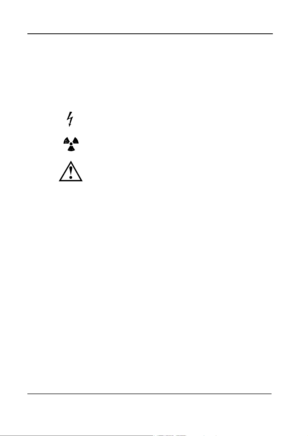
Explanation of Symbols
The following symbols are used in the technical documents:
Measuring and adjusting work on parts which are under a
voltage of >50 VAC or >120 DC.
Activities with radiation switched ON.
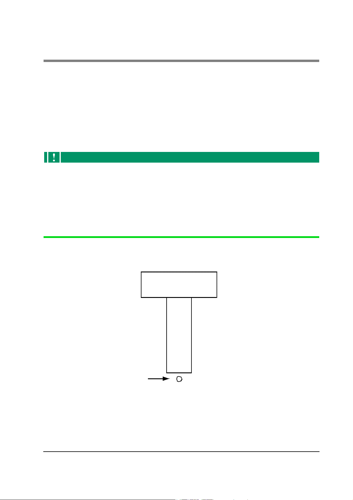
Safety-relevant screw connections.
491-7181-3501Mx8000 Systems Installation Manual
Use only the (supplied) screw connections that are suitable for
the intended purpose and tighten with the specified torque.
General Precautions
This product was designed and manufactured to ensure maximum safety of
operation and service. It should be installed, maintained, and serviced in strict
compliance with the safety instructions contained herein.
1. No changes, additions, or removal of any system accessories are permitted
without the prior written approval of a local service manager.
2. Connect the product to the mains according to the wiring scheme in this
manual.
3. Before beginning any clinical use, complete all safety checks in this manual.
4. Do not leave problems unsolved that may affect the safety of the product. In
case of doubt concerning the system's safe operation, call the service manager
for further instruction.
5. Do not allow unauthorized personnel access to the system. Only properly
trained and fully qualified personnel are authorized to install and operate this
equipment.
Philips Medical Systems. Confidential and Proprietary information. Refer to Title Page.
2-2

491-7181-3501 Mx8000 Systems Installation Manual
Safety
Service Precautions
Safety precautions must be taken before servicing the machine. It is the
responsibility of the service engineer to ensure that these precautions are taken to
avoid any hazard.
There are three different kinds of potential hazard when servicing an instrument
like the Mx8000:
• Mechanical hazards
• Electrical hazards
•Radiation Hazards
Philips Medical Systems. Confidential and Proprietary information. Refer to Title Page.
2-3

Service Precautions
Precautions Against Mechanical Hazards
WARNING
Rotating machinery— never service the rotating frame when or if rotational
movement is enabled. Failure to comply may result in equipment damage, serious
injury or death to service personnel.
The following precautions prevent mechanical hazards:
1. The Rotor of the Mx8000 contains heavy parts, such as the High Voltage
Power Supply, DMS, etc., and is perfectly balanced. When you disturb this
balance by removing a part from it, it will start an uncontrolled mechanical
motion to reach a new equilibrium point. This motion cannot be stopped and
may injure the service engineer.
Therefore, if you intend to remove a unit, proceed as follows:
a. Bring the Rotor to the position in which the unit can be removed.
491-7181-3501Mx8000 Systems Installation Manual
b. When the Rotor is not rotating, engage the rotor locking device (located
on the front side of the Gantry at the 2 o’clock position).
c. Do not release the rotor locking device until the unit (or its replacement)
is returned and fixed securely to the Rotor.
2. In its idle state, the Mx8000 rotates most of the time; consider all units
mounted on the rotor as flying units. If you fail to fasten units to the Rotor
securely or leave loose screws, units may detach from the Rotor and cause
serious injury.
After servicing any unit, verify that all units and screws are attached securely
in their correct places.
3. The Rotor has no fixed idle position, and even when it is not generating
X-Rays it may start rotating. An uncontrolled, electricity-driven rotation may
cause serious injuries. For this reason, two microswitches in the front cover
disable rotation each time the front cover is opened. In addition, another
switch (S301) on the inner left side of the Gantry also disables rotation.
Do not bypass the two front cover switches unless no person is near the
Gantry, and it is absolutely necessary.
Never approach the Gantry when or if rotational movement is enabled.
Philips Medical Systems. Confidential and Proprietary information. Refer to Title Page.
2-4

491-7181-3501 Mx8000 Systems Installation Manual
Safety
Precautions Against Electrical Hazards
The following precautions prevent electrical hazards:
1. Being a continuous rotating scanner means that the power is transmitted to
the rotating part by mechanical slip rings. Over the slip rings there are line
voltages. Once you remove the rear cover, you may be in contact with line
voltages.
CAUTION
Front end electronics is energized through the slip rings even when you switch
off the system.
Therefore, before you remove the rear cover, to avoid any electrical danger,
switch off all circuit breakers on the Power Distribution Cabinet (PDC), and on the
main power supply to the Mx8000.
2. The Computer Rack and the Operating Console receive power from an
Uninterruptible Power Supply (UPS) located in the Power Distribution
Cabinet (PDC). This means that parts inside these units continue to receive
line voltages, even after the console or the various circuit breakers are
switched off.
Disconnect the Rack and Console power cables before accessing these units.
3. Line voltages are always present in the Gantry’s left leg. Therefore, make
sure that the left leg cover is always closed, unless otherwise necessary for
service.
4. Remember that the PDC is energized even when the system is OFF.
Therefore, always keep the door of the PDC closed. When you must service
the PDC, first disconnect the power supply.
The system has large capacitors. Therefore, wait for a few minutes after
disconnecting the power to the system before servicing the high voltage (HV)
system on the Rotor and in the PDC.
Electrical Installations
Electrical installations of medically used rooms must comply with the
requirements of each country. Follow the regulations from the installation sheets
for the specific project.
Installation of Electromedical Systems and Equipment
All work must be carried out in accordance with the technical documentation.
Philips Medical Systems. Confidential and Proprietary information. Refer to Title Page.
2-5

Service Precautions
Make sure that all protective ground wires provided by the manufacturer are
connected properly before powering the equipment. This applies, for example, to
all metallic covers which may develop a dangerous contact voltage in case of a
fault. They must always be connected to the protective ground wire. To ensure
this, the connection between these covers and the protective ground wire must be
made with screws and contact washer or via the protective ground wires provided.
The protective ground wires must be connected between the system components
and the power supply as shown in the wiring diagram.
In the interest of protection for our personnel, the protective ground wires must be
installed prior to first switching on the product/system, as well as after completing
all work, before turnover to the customer, in accordance with the product
documentation.
491-7181-3501Mx8000 Systems Installation Manual
Means “Terminal for connection of equipment protective
ground wire”.
Personal Protection Measures (Occupational Safety)
The legally relevant and internal regulations and specifications concerning
protection of labor and accident prevention must be observed, primarily in the
interest of the persons performing the work. The notes below are given as
additional information.
Working When Connected to Voltages
Do not perform any work on current-carrying parts (>50 V ~ or 120 V).
Turn OFF energy to the system by means of the EMERGENCY OFF switch.
This prohibition does not apply for measuring and adjustment procedures. Be
careful when performing these procedures. Use only tools and measuring
instruments which are suitable for the respective procedure.
Test and adjustment points must be accessible without any risk of injury to the
personnel. If this is not possible, switch OFF the system.
If voltage must be applied during an operation, e.g., to perform unit movements,
take every precaution especially when working with moving and rotating parts.
Turn OFF energy to the unit immediately afterwards.
WARNING
When performing work within the danger area of products, any involuntary unit
movements must be prevented by previously actuating the service switch or the
EMERGENCY STOP button.
Philips Medical Systems. Confidential and Proprietary information. Refer to Title Page.
2-6

491-7181-3501 Mx8000 Systems Installation Manual
Safety
Body Protectors
If there is any risk of injury, use body protectors. It is essential to take the
protective measures described in the documentation.
Radiation Protection
Ionizing radiation can lead to radiation injuries, if handled incorrectly. When
radiation is applied, comply with the require protective measures at all times.
WARNING
Blood-borne Pathogens
When handling parts that may have come into contact with patients, take appropriate
precautions against exposure to blood-borne pathogens
Mandatory Reporting
Notify the supervisor in charge, at once, in the event of an accident or if there are
any hazards that may cause an accident.
Instruments used for PM
Never use worn or defective instrument
Using the Right Torque for Screw Connections
Tighten all existing screw connections firmly, but not so that they are
overstressed (see
Section Attaching Screws and Nuts on page 14).
CAUTION
• Use torque wrenches that overgo periodic checks and calibrations and that are
within the period of certified validity.
• Use only the indicated torque at all times.
• Secure all screws in accordance with the corresponding data.
• If LOCTITE must be used to secure screws, it is stated in the text.
Protection of Electrostatically Sensitive Devices
Integrated circuits and PC boards that are equipped with electronic modules
require special careful handling, because of their electrostatic sensitive structures
and their extremely high input impedances.
Use the indicated means of protection.
Philips Medical Systems. Confidential and Proprietary information. Refer to Title Page.
2-7

Service Precautions
Laser Radiation
Laser radiation can lead to eye and skin injuries (Class 3b and Class 4). Note the
relevant instructions in the documentation.
Batteries
For replacement of batteries, special preventive measures apply. With lithium
batteries, there is a risk of explosion if they are incorrectly installed. Observe the
notes concerning handling and disposal in each case.
Handling Heavy Loads
In addition to wearing the required protective clothing, e.g., safety boots and
gloves, take care that heavy loads are correctly lifted or carried to avoid any
physical injury (e.g., injuring the spine).
The relevant instructions must be complied with.
491-7181-3501Mx8000 Systems Installation Manual
Move heavy or awkward loads by mechanical means or using several persons.
Handling Hazardous Substances
A hazardous substance is any material that can ignite or explode, or that is toxic,
injurious to health, corrosive or irritating.
The properties of hazardous substances, together with the hazards and protective
measures connected with them, are identified clearly by symbols and handling
instructions attached to them.
Before handling them, read these instructions and take the required protective
measures to avoid health risks during work.
Comply with all relevant instructions in the documentation.
Philips Medical Systems. Confidential and Proprietary information. Refer to Title Page.
2-8
 Loading...