

Page 1
MX4000/6000 Dual and
MX4000
System Installation Instructions
4550 193 80401
Revision D
This document and the information contained in it is proprietary and confidential information of Philips Healthcare ("Philips") and may not be reproduced,
copied in whole or in part, adapted, modified, disclosed to others, or disseminated without the prior written permission of the Philips Legal Department.
Use of this document and the information contained in it is strictly reserved for current Philips personnel and Philips customers who have a current and
valid license from Philips for use by the customer’s designated in-house service employee on equipment located at the customer’s designated site. Use
of this document by unauthorized persons is strictly prohibited. Report violation of these requirements to the Philips Legal Department. This document
must be returned to Philips when the user is no longer licensed and in any event upon Philips’ first written request.
© 2010 Philips Healthcare
Page 2

Philips Healthcare
„ 2010 KONINKLIJKE PHILIPS ELECTRONICS N. V. ALL RIGHTS RESERVED.
Warranty Disclaimer
PHILIPS PROVIDES THIS DOCUMENT WITHOUT WARRANTY OF ANY KIND, EITHER IMPLIED OR EXPRESSED,
INCLUDING, BUT NOT LIMITED TO, THE IMPLIED WARRANTIES OF MERCHANTABILITY AND FITNESS FOR A
PARTICULAR PURPOSE.
Limitation of Liability
OR CHANGES IN THE PRODUCT(S) OR PROGRAM(S) DESCRIBED IN THIS DOCUMENT AT ANY TIME.
Password Notice
Page 3

Symbol Descriptions
Attention symbol Radiation warning symbol
Laser warning symbol Biohazard warning symbol
Magnetism warning symbol Projectile warning symbol
Electrical warning symbol Do not touch
Page 4

Revision History
ECO # Revision Date Comments
New Release
Removed Gantry Rotation Locking Pin Release Procedure
H3000384 A November 2006
H3000423 B January 2007
H3000753 C July 2007
Updated “Cable Connection Overview” on page 48
Updated “Connecting the UPS (Option)” on page 67
Updated “Service license Key” on page 96
Updated:
“Connecting the Computer Rack” on page 59
“Connecting the UPS (Option)” on page 67
Added: “Record X-ray Exposure Times” on page 113
Changes to “Packing List” on page 4 and “Shipping Case Contents” on page 5
Isolation Transformer now called “Unpacking & Transporting System Units” on page 7
Changes in “Transport Specifications” on page 8
Added section “Changing the Warning Labels” on page 73
Changes in “Power Filter Box or Isolation Transformer” on page 27 options
Page 5

ECO # Revision Date Comments
“ Shipping Case Contents” on page 5
Modified “Connecting the CT-Box” on page 57
Modified “Connecting the CT-Box Interface Board” on page 66
Deleted “Connecting the Network switch”
Modified “Record X-ray Exposure Times” on page 113
Modified “Dell Service Tag Transfer” on page 116
Modified “ Leveling the Gantry” on page 90
Modified “Positioning the Gantry” on page 29
Modified “Connecting the Patient Table” on page 56
Modified “Connecting the Computer Rack” on page 59
Added “Setting the Console Power Management for UPS Option” on page 132
Modified “Packing List” on page 4
Modified “Unpacking the Patient Table” on page 18
Modified “Positioning the Patient Table” on page 30
Modified “Power Filter Box or Isolation Transformer” on page 27
Modified “Preface” on page 111
Added “Power Filter Box (ROW - Out of China Configuration)” on page 124
Updated “Power Supply Troubleshooting” on page 135
This document was prepared by the CT BU Haifa Service Innovation Department.
For any additions, corrections, or suggestions, contact:
CT BU Haifa Customer Support Department
Email: helpdesk.ct.haifa@philips.com
Page 6

Safety Information
To the User of This Manual
The user of this manual is directed to read and carefully review the instructions, warnings and cautions contained herein prior to beginning installation or service activities.
While you may have previously installed or serviced equipment similar to that described in this manual, changes in design, manufacture or procedure may have occurred
which significantly affect the present installation or service.
Installation and Environment
Except for installations requiring certification by the manufacturer per federal standards, see that a radiation protection survey is made by a qualified expert in accordance
with NCRP 102, section 7, as revised or replaced in the future. Perform a survey after every change in equipment, workload, or operating conditions which might
significantly increase the probability of persons receiving more than the maximum permissible dose equivalent.
Diagnostic Imaging Systems - Mechanical-electrical Warning
All of the moveable assemblies and parts of this equipment should be operated with care and routinely inspected in accordance with the manufacturer’s recommendations
contained in the equipment manuals.
Only properly trained and qualified personnel should be permitted access to any internal parts. Live electrical terminals are deadly; be sure line disconnects are opened and
other appropriate precautions are taken before opening access doors, removing enclosure panels, or attaching accessories.
Do not under any circumstances, remove the flexible high tension cables from the x-ray tube housing or high tension generator and/or the access covers from the generator
until the main and auxiliary power supplies have been disconnected. Failure to comply with the above may result in serious or fatal bodily injuries to the operator or those
in the area.
The equipment must be grounded to an earth ground by a separate conductor. The neutral side of the line is not to be considered the earth ground. On equipment
provided with a line cord, the equipment must be connected to properly grounded, three-pin receptacle. Do not use a three-to-two pin adapter.
Diagnostic Imaging Systems - Radiation Warning
X-ray and Gamma-rays are dangerous to both operator and others in the vicinity unless established safe exposure procedures are strictly observed.
The useful and scattered beams can produce serious or fatal bodily injuries to any persons in the surrounding area if used by an unskilled operator. Adequate precautions
must always be taken to avoid exposure to the useful beam, as well as to leakage radiation from within the source housing or to scattered radiation resulting from the
passage of radiation through matter.
Those authorized to operate, participate in or supervise the operation of the equipment must be thoroughly familiar and comply completely with the current established
safe exposure factors and procedures described in publications, such as: Subchapter J of Title 21 of the Code of Federal Regulations, "Diagnostic X-ray Systems and Their
Major Components", and the national council on radiation protection (NCRP) no. 102, "Medical X-ray And Gamma-ray Protection For Energies Up To 10 Mevequipment Design and Use", as revised or replaced in the future.
Those responsible for planning of x-ray and gamma-ray equipment installations must be thoroughly familiar and comply completely with NCRP no. 49, "Structural
Shielding Design and Evaluation For Medical Of X-rays and Gamma-rays of Energies Up to 10 Mev", as revised and replaced in the future. Failure to observe these
warnings may cause serious or fatal bodily injuries to the operator or those in the area.
Add additional safety information as needed
Page 7

Contents
Introduction 1
How this Manual is Organized .................................................................................................................................................. 1
Safety........................................................................................................................................................................................ 1
Implementation Order and Time Table ..................................................................................................................................... 2
Pre-installation .................................................................................................................................................................... 2
Implementation ................................................................................................................................................................... 3
Packing List............................................................................................................................................................................... 4
Shipping Case Contents ........................................................................................................................................................... 5
Unpacking & Transporting System Units 7
Gantry ....................................................................................................................................................................................... 8
Delivery Method Instructions............................................................................................................................................... 8
Transport Specifications ..................................................................................................................................................... 8
Unloading the Gantry .......................................................................................................................................................... 9
Forklift Specifications .................................................................................................................................................... 9
Unpacking the Gantry ......................................................................................................................................................... 10
Releasing the Gantry from the Pallet .................................................................................................................................. 11
Attaching the Transport Dollies........................................................................................................................................... 12
Transporting the Gantry ...................................................................................................................................................... 14
Transporting Guidelines................................................................................................................................................ 14
Transporting the Gantry through Doors and Hallways .................................................................................................. 15
Transporting the Gantry through Minimum Width Clearance........................................................................................ 16
The Patient Table...................................................................................................................................................................... 18
Unpacking the Patient Table............................................................................................................................................... 18
Workspace and Accessories..................................................................................................................................................... 26
Power Filter Box or Isolation Transformer ................................................................................................................................ 27
Positioning System Components 28
Checking the Rotating Frame ................................................................................................................................................... 28
Positioning the Gantry............................................................................................................................................................... 29
Removing the Base Covers ................................................................................................................................................ 29
Positioning the Patient Table .................................................................................................................................................... 30
Positioning the Connection Piece ............................................................................................................................................. 33
Positioning the Operating Console ........................................................................................................................................... 34
Operator’s Table ................................................................................................................................................................. 35
Assembly Steps ............................................................................................................................................................ 36
Computer Rack ................................................................................................................................................................... 39
CSIP Level 0 © 2010 Koninklijke Philips Electronics N.V All Rights Reserved Refer to Front Cover i
Page 8

Contents
Changing Computer Rack Door Orientation ................................................................................................................. 39
Installing the System 47
Cable Connection Overview ..................................................................................................................................................... 48
Routing the System Cables ................................................................................................................................................ 49
Routing the External System Cables .................................................................................................................................. 49
Installing the Power Distributor (Power Supply Devices and/or Power Protector).................................................................... 50
Connecting the Gantry.............................................................................................................................................................. 51
Routing the Signal and Power Cables ................................................................................................................................ 51
Connecting the Gantry Right Column ................................................................................................................................. 53
Input Power Connection................................................................................................................................................ 53
Door Interlock and X-ray Lamp ON Connections.......................................................................................................... 54
Connecting the Gantry Left Column.................................................................................................................................... 55
Connecting the Patient Table.................................................................................................................................................... 56
Connecting the Operating Station............................................................................................................................................. 57
Connecting the Operating Table ......................................................................................................................................... 57
Connecting the CT-Box................................................................................................................................................. 57
Connecting the Monitor................................................................................................................................................. 58
Connecting the Computer Rack.......................................................................................................................................... 59
Connecting Power to the Computer Rack..................................................................................................................... 62
Connecting Power Cables to the Multi-outlet................................................................................................................ 63
Connecting the UPS (Option) ............................................................................................................................................. 67
Tools ............................................................................................................................................................................. 67
UPS Package Contents ................................................................................................................................................ 68
Installing the UPS.......................................................................................................................................................... 69
Final Steps .................................................................................................................................................................... 72
Changing the Warning Labels................................................................................................................................................... 73
Pre-start-up Procedures 76
System Power Up ..................................................................................................................................................................... 77
Verifying Output Power Voltage.......................................................................................................................................... 77
Opening the Gantry Front and Rear Covers............................................................................................................................. 80
Checking the Protective (GND) Covers .................................................................................................................................... 83
Gantry GND Check ............................................................................................................................................................. 84
Gantry Stationary .......................................................................................................................................................... 84
Gantry Rotor Frame ...................................................................................................................................................... 85
Computer Rack ................................................................................................................................................................... 86
Patient Table....................................................................................................................................................................... 87
CSIP Level 0 © 2010 Koninklijke Philips Electronics N.V All Rights Reserved Refer to Front Cover ii
Page 9

Contents
Ensuring Air-conditioning Readiness ........................................................................................................................................ 87
Checking Manual Rotation and Tilt ........................................................................................................................................... 88
System Leveling and Anchoring 89
Inserting the Anchor Bolts......................................................................................................................................................... 89
Gantry ....................................................................................................................................................................................... 90
Leveling the Gantry............................................................................................................................................................. 90
Adding Shims ................................................................................................................................................................ 92
Final Anchoring of the Gantry ............................................................................................................................................. 92
Removing the Transport Dollies.......................................................................................................................................... 92
Patient Table............................................................................................................................................................................. 93
Leveling the Patient Table .................................................................................................................................................. 93
Verifying and/or Installing the License Keys 94
Option License Key................................................................................................................................................................... 94
Service license Key................................................................................................................................................................... 96
Setting Hospital Name and License Key Expiration.................................................................................................................. 96
Setting Hospital Name ........................................................................................................................................................ 96
License Key Expiration ....................................................................................................................................................... 97
First Time System Operation 98
Closing Duct Covers ................................................................................................................................................................. 99
Closing Gantry Covers.............................................................................................................................................................. 99
Gantry Base Covers............................................................................................................................................................ 99
Gantry Rear Cover.............................................................................................................................................................. 100
Gantry Front Cover ............................................................................................................................................................. 101
Gantry Side Covers............................................................................................................................................................. 102
Gantry Right Column Cover .......................................................................................................................................... 102
Gantry Left Column Cover ............................................................................................................................................ 102
Position the Connection Piece Cover ....................................................................................................................................... 103
Ensuring Safety Measures........................................................................................................................................................ 104
Checking the Emergency Shutdown Buttons...................................................................................................................... 105
Checking the Door Contact Switch ..................................................................................................................................... 105
Checking the Gantry Fans .................................................................................................................................................. 105
Checking Movement from the Gantry Panel ....................................................................................................................... 105
Checking Movement from the CT-Box................................................................................................................................ 107
Checking Reconstruction and Image Display ........................................................................................................................... 107
CSIP Level 0 © 2010 Koninklijke Philips Electronics N.V All Rights Reserved Refer to Front Cover iii
Page 10

Contents
Final Patient Table Alignment and Anchoring........................................................................................................................... 107
Final Patient Table Checks ....................................................................................................................................................... 108
Checking Gantry and Patient Table Collision ..................................................................................................................... 108
Gantry Tilt Angle Graph ................................................................................................................................................ 109
Closing Patient Table Covers ............................................................................................................................................. 110
Acceptance Test 111
Preface...................................................................................................................................................................................... 111
Gantry Balance Check.............................................................................................................................................................. 112
Record X-ray Exposure Times.................................................................................................................................................. 113
Network Installation and Configuration 114
Setting the Date and Time Properties 114
Performing Backup 115
Dell Service Tag Transfer 116
Delivery and Installation Report 117
Appendix A: Using the Floor Template to Drill Gantry Anchor Holes 118
Positioning the Floor Template ................................................................................................................................................. 119
Drilling the Gantry and Patient Table Anchor Holes ................................................................................................................. 121
Installing the Concrete Floor Anchors....................................................................................................................................... 122
Recommendation for Subfloor Construction for Installation Floor ...................................................................................... 122
Appendix B: Installing the Power Filter Box or Isolation Transformer 123
Power Filter Box (ROW - Out of China Configuration).............................................................................................................. 124
Procedure to install Power Filter Box.................................................................................................................................. 125
HuaRan Isolation Transformer (China only) ............................................................................................................................. 127
Teal Isolation Transformer (ROW Optional - Out of China Configuration)................................................................................ 128
Appendix C: Selecting System Language 129
CSIP Level 0 © 2010 Koninklijke Philips Electronics N.V All Rights Reserved Refer to Front Cover iv
Page 11

Contents
Appendix D: Modifying the Lateral Laser Position 130
Appendix E: Modifying the Image Rotation Angle 131
Appendix F: Setting the Console Power Management for UPS Option 132
Appendix G: Power Supply Troubleshooting 135
CSIP Level 0 © 2010 Koninklijke Philips Electronics N.V All Rights Reserved Refer to Front Cover v
Page 12

MX4000/6000 Dual and MX4000 Single System Installation Instructions
Introduction
This manual defines the installation procedures applied to the MX 4000/6000 Dual and MX 4000 CT system. Ensure
that all steps described in the Pre-installation Manual are completed before system installation.
Only certified Philips CT Engineers and authorized distributors shall install the MX 4000/6000 Dual and MX 4000 CT
scanner.
Prior to the start of the installation, a Philips Service Engineer, together with the Hospital’s facility representative and
local Philips Project Manager are required to inspect the site. Individual site layout and environmental specifications are
reflected in the final site planning drawings. All materials needed for installation are included with the scanner.
How this Manual is Organized
This installation manual is organized in the order of procedures necessary to install the MX 4000/6000 Dual and MX
4000 CT scanner. This manual complies with Philips Medical Systems service documentation format. Its landscape
format is intended for easy viewing on the Field Service Engineer’s computer. In addition to the bookmarks displayed in
Acrobat Reader, the user can take advantage of the Table of Contents in the beginning of the manual. These
navigation tools enable the FSE to find the necessary information quickly.
Introduction
Safety
WARNING PRIOR TO INSTALLATION READ AND UNDERSTAND ALL GUIDELINES IN THE
SAFETY MANUAL.
CSIP Level 0 © 2010 Koninklijke Philips Electronics N.V All Rights Reserved Refer to Front Cover 1
Page 13

Implementation Order and Time Table
Pre-installation
Make sure that all pre-installation procedures have been performed and that the site is ready for delivery of the system.
For all detailed information pertaining to Room requirements and system Planning Data, refer to the on-line PRD
(Planning Reference Data), section 728 on TechNet as follows:
1 Log on to at:
http://incenter.medical.philips.com/Default.aspx?tabid=43&PTLLObjId=356730.
NOTE InCenter requires log in with User ID (your email— firstname.lastname@philips.com) and password
(IST password).
2 Under Tools and Resources (right side of the screen), click Planning Reference Data.
3 On the Homepage PRD, click Current Products | 728 Computed Tomograph | Commercial Catalogue |
MX 4000/6000.
Site preparation includes (partial list):
• Planning room layout
• Environmental conditions
• Power requirements
• Safety protection requirements
• Drilling anchor holes
CSIP Level 0 © 2010 Koninklijke Philips Electronics N.V All Rights Reserved Refer to Front Cover 2
Page 14

Implementation
It is most important to perform the pre-installation and installation tasks in the order shown in Tab le 1. Estimated time for
each installation operation is included. The total estimated time (not including pre-installation tasks) is three days.
Number Activity Estimated Time
1 Completing site preparation and Site Inspection checklist Pre-installation
2 Unpacking and positioning units 2
3 Anchoring units 2
4 Connecting system components 2
5 Preparing the system for operation Half a day
6 System first time operation and functional checks Half a day
7 Preparing system for clinical operation 1 day
*Some times estimates assume two people and/or no seismic requirements for installation of the system.
Table 1: Implementation Order
CSIP Level 0 © 2010 Koninklijke Philips Electronics N.V All Rights Reserved Refer to Front Cover 3
Page 15

Packing List
Table 2 lists the shipping cases that are included in a delivery of the MX 4000/6000 Dual and MX 4000 system. For
shipping case contents, refer to Shipping Case Contents.
Table 2: Component Weights and Sizes
Component
Item #
1 Gantry
2 Patient Table
3 Accessories
Huaran Isolation Transformer
4
(Optional China only)
37 kVA Teal Isolation Transformer
6
(Optional)
Dimensions (L x W x H in mm)
Dimensions (L x W x H in inches)
Net Package Net Package
2210 x 850 x 1890
87 x 33.5 x 74.4
2440 (max) x 575 x 1100 (max)
96 x 22.6 x 43.3
600 x 450 x850
23.6 x 17.7 x 33.5
2370 x 1030 x 2320
93 x 40.6 x 91.3
2570 x 970 x 1220
101 x 38.2 x 48
1220 x 1160 x 870
47.2 x 45.7 x 34.3
700 x 640 x 1200
27.6 x 25.2 x 47.2
516x552x712
20.3x21.7x28
Weight in kg
Weight in lb
1700
3748
350
772
240
529
2000
4409
450
992
260
573
260
573
274
604
CSIP Level 0 © 2010 Koninklijke Philips Electronics N.V All Rights Reserved Refer to Front Cover 4
Page 16

Shipping Case Contents
Item #1 Gantry - Contents Qty
Gantry 1
Item #2 Patient Table - Contents Qty
Patient Table 1
Patient Table Cushion 1
Connection Piece ASSY 1
Gantry Mylar 2
CSIP Level 0 © 2010 Koninklijke Philips Electronics N.V All Rights Reserved Refer to Front Cover 5
Page 17

NOTE Tools listed below are shipped with the system. These tools do not replace the standard FSE tool kit
(prerequisite for system installation and maintenance).
Item #4 Accessories - Contents Qty Item #4 Accessories - Contents Qty
Work desk 1 System Phantom for Image Quality checks 1
Computer Rack (without Host Computer) 1 7” Water phantom 1
Host Computer 1 10” Water phantom 1
19” LCD Monitor 1 14” Water phantom 1
CT Box 1 Step phantom 1
Rack PE cable (W417) 1 Grease Gun (with 2 plugs) 1
Line power cable (W403) 1 Manual Box 1
Gantry power supply cable (W101) 1 Quality certification 1
Network cable (W119) 1 Testing report 1
CT BOX cable 1 (W124) 1 Installation Template 1
CT BOX cable 2 (W125) 1 Shims A 10
Head holder (with one head strap) 1 Shims B 4
Coronary chin pad 1 Caps for screw hole 21
Neck pad 1 16x200 drill bit 1
Head holder Cushion 1 18x200 Drill bit 1
Knee pad 1 Patient Table Anchoring Bolts - M12x110 5
Extended board to cradle (optional) 1 Gantry Anchoring Bolts - M14x123 5
Water phantom support 1 Operator table box 1
FSE toolbox 1
Warning Label Assy 1
CSIP Level 0 © 2010 Koninklijke Philips Electronics N.V All Rights Reserved Refer to Front Cover 6
Page 18

MX4000/6000 Dual and MX4000 Single System Installation Instructions
Left Right
Person
Unpacking & Transporting System Units
Careful unpacking and transporting of the system units will help to prevent damage to the equipment and make
installation easier.
This chapter provides instructions to unpack and transport the following units, in the order listed:
Gantry
The Patient Table
Workspace and Accessories
Power Filter Box or Isolation Transformer
Refer to Section Shipping Case Contents when unpacking to verify that you have received all system components
listed. In the event that any component is missing, contact CT Customer Support immediately for further instructions.
If a unit shows external or internal damage, contact the transportation company and file a damage claim under ICC
regulations. In addition, contact the CT Customer Support immediately for further instructions.
Unpacking & Transporting System Units
NOTE Left and right references in this manual are from the point of view of a person standing at the open end
of the Patient Table, facing the Gantry as shown in Figure 1.
Figure 1:
CSIP Level 0 © 2010 Koninklijke Philips Electronics N.V All Rights Reserved Refer to Front Cover 7
Page 19

Gantry
Delivery Method Instructions
To prevent damage to the system, transport the system on site only as described in this chapter.
CAUTION Transport the entire system in its original packaging.
CAUTION The truck used to transfer the system must have shock absorbers.
Transport Specifications
During transportation, the environment must meet the following conditions:
Temperature in °C (°F) -30°C ~ +55°C (-22°F ~ 131°F)
Gradient Temperature in °C (°F) /hour 5°C (-41°F)
Humidity in% (non-condensing) 10%—90%, non-condensing
Atmosphere pressure: 50Kpa~106Kpa
CSIP Level 0 © 2010 Koninklijke Philips Electronics N.V All Rights Reserved Refer to Front Cover 8
Page 20

Unloading the Gantry
Unload the Gantry from truck by forklift with extension arm and then place it on the aisle that leads to the scanning room
on the same level.
Forklift Specifications
The forklift must be a minimum load of 3000 kg and able to balance a load that is 2.4 M long with center of gravity at
midpoint when lowering the crate from the truck and transporting it.
Fork specifications:
max.184 mm wide by 57 mm high
minimum 1524 mm length
Both forks must spread 610 mm apart (center to center)
Dolly wheels must be obtained locally from the SSD or Regional Office.
CAUTION If there is an incline exceeding 5° or if there are steps on the aisle, the Gantry must be
unloaded with its packing box onto the aisle or steps.
CSIP Level 0 © 2010 Koninklijke Philips Electronics N.V All Rights Reserved Refer to Front Cover 9
Page 21
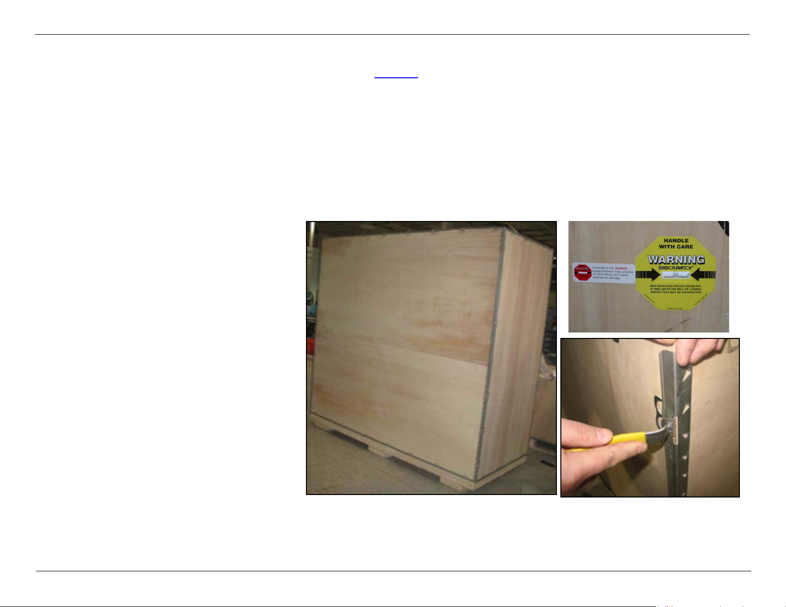
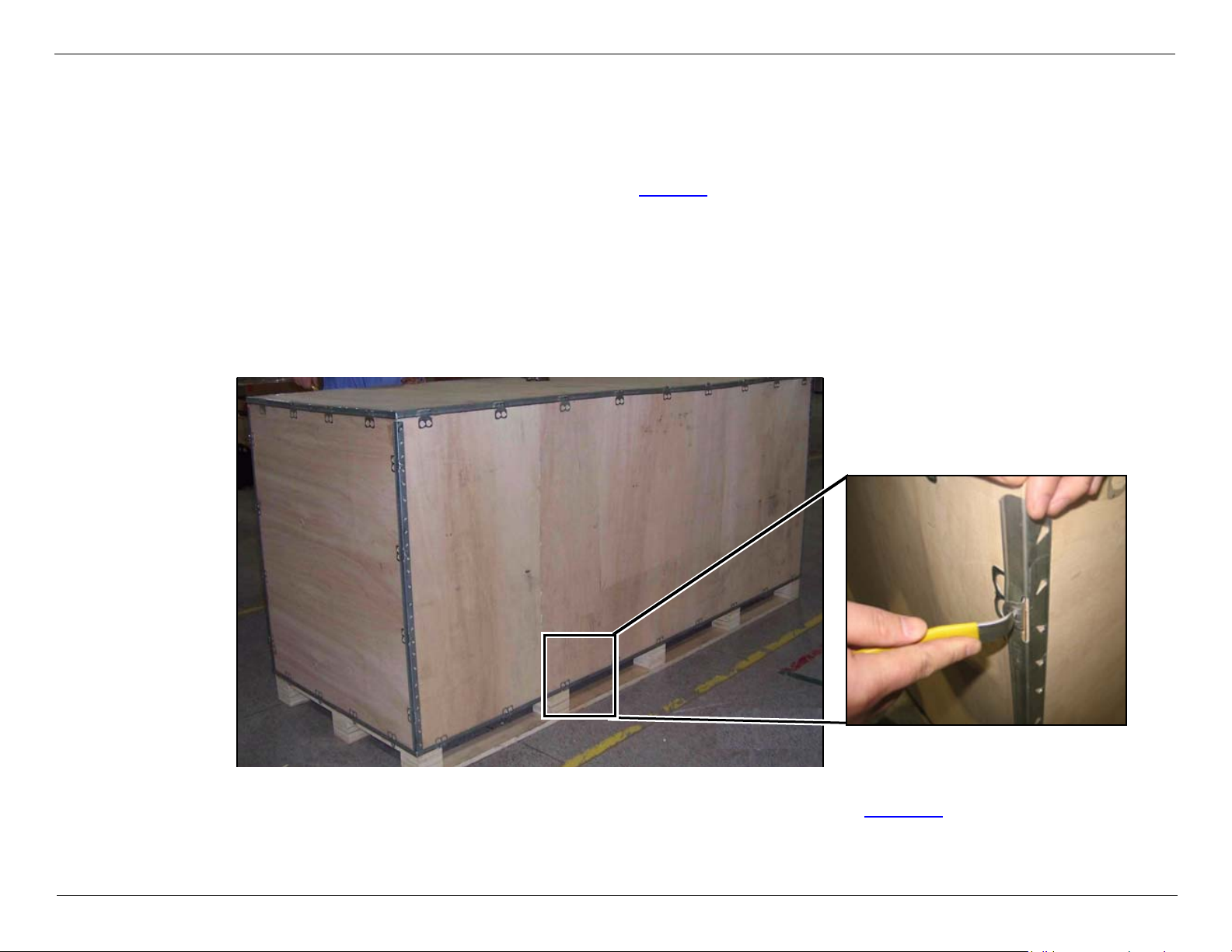
Unpacking the Gantry
The Gantry is delivered in a packing crate (see Figure 2) equipped with a Shockwatch device that will indicate if the
crate has sustained a shock above tolerance level while in transit.
Before opening the crate, observe the Shockwatch device. If damage is indicated, contact the SSD or local service
support.
WARNING Take all necessary safety precautions when opening the gantry crate. Use safety
equipment such as gloves, reinforced shoes, etc.
NOTE The unpacking tool can be ordered prior to installation, and is found in the shipped-with package.
Unpack as follows:
1 Release the clamps that
secure the packing crate top
and carefully remove it.
2 Release the clamps from all
four sides and lower them
carefully.
3 Remove the anti-static
wrapping covering the
Gantry.
Figure 2:
CSIP Level 0 © 2010 Koninklijke Philips Electronics N.V All Rights Reserved Refer to Front Cover 10
Page 22
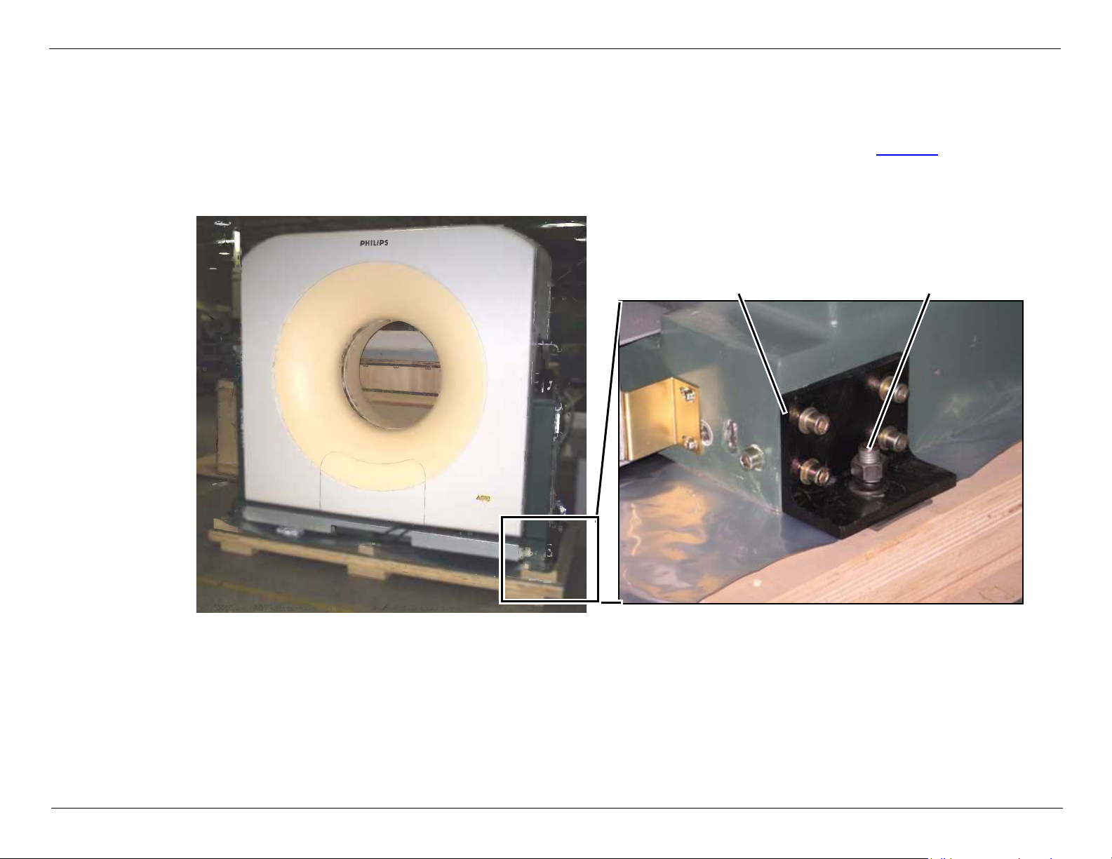
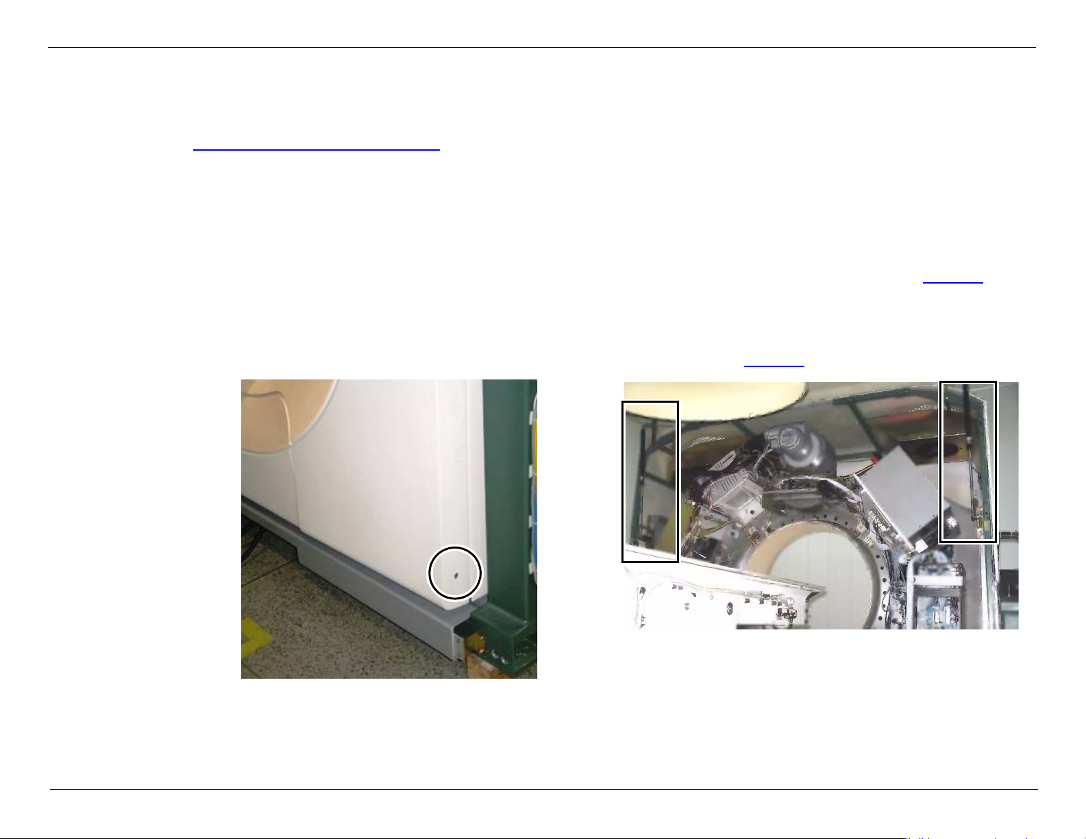
Releasing the Gantry from the Pallet
Gantry secure screwShipping bracket
1 Remove the Gantry side covers.
2 There are two bolts on each side of the Gantry that secure the shipping brackets to the pallet. Release all nuts and
washers and push the bolts down so that the Gantry is now released from the pallet (see Figure 3).
3 Use a 23mm crescent wrench or open wrench to release the four screws that secure the shipping bracket to the
Gantry.
Figure 3:
CSIP Level 0 © 2010 Koninklijke Philips Electronics N.V All Rights Reserved Refer to Front Cover 11
Page 23

MX4000/6000 Dual and MX4000 Single System Installation Instructions
NOTE
Securing bolt Transportation adapter
NOTE Verify that the transportation adapter is installed, before you install the Gantry dollies
Unpacking & Transporting System Units
1 Attach all four transport dollies (see Figure 4
sides of the Gantry and fasten with the securing bolt.
If you have difficulty inserting the security bolt, loosen
the two adjacent screws to allow freer movement.
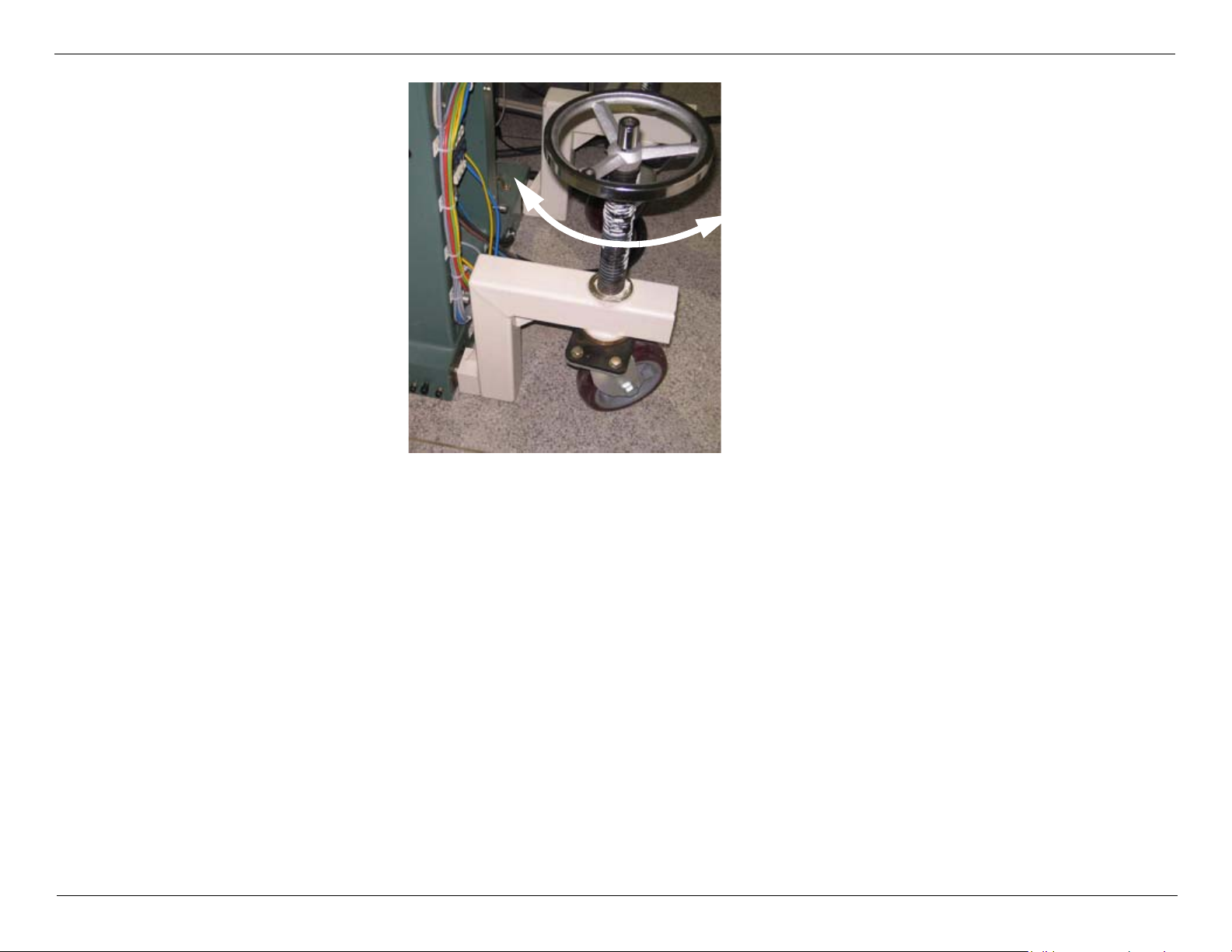
2 Rotate the hand wheels of the transport devices
clockwise to lower the rollers to the floor.
3 Continue rotating each of the hand wheels clockwise to
raise the Gantry with the transport dollies until it clears
the pallet (see Figure 5).
) to both
Figure 4: Securing Dollies
WARNING Rotate the hand wheels of all four dollies alternately so that the gantry remains
straight and does not lean.
WARNING crush hazard. minimize the clearance between the Gantry base and the floor
when transporting the Gantry. this will prevent excess stress on the jack screws
and to reduce the possibility of tipping the Gantry. failure to comply may result
in serious injury or death to service personnel.
4 Remove the pallet.
5 Rotate each of the hand wheels counter-clockwise until the Gantry base is clear of the floor by approximately
CSIP Level 0 © 2010 Koninklijke Philips Electronics N.V All Rights Reserved Refer to Front Cover 12
15 mm. The Gantry is prepared for transport. Push on its solid surfaces in the lower half of the Gantry.
Page 24
MX4000/6000 Dual and MX4000 Single System Installation Instructions
Turn hand wheel:
• Clockwise - raise Gantry
• Counter-clockwise -
lower Gantry
Unpacking & Transporting System Units
Figure 5:
CSIP Level 0 © 2010 Koninklijke Philips Electronics N.V All Rights Reserved Refer to Front Cover 13
Page 25

Transport the Gantry as follows:
— Ensure that the floor load for the transport path as well as the installation rooms has been approved by a
structural engineer prior to the installation. Installation floors must be laid out to support a load of min. 400 kg/
plate. During transport of the Gantry, higher loads can occur at individual points (3-point load, e.g., if the floor is
not level). Cover the transport path with sheet metal to distribute the floor load.
— Use the rollers of the transport dollies to move the Gantry to the installation location.
— Turn the rollers of the transport dollies in the direction that the Gantry is to be moved.
— To avoid damage, do not move the transport dollies over obstructions.
— Do not transport the Gantry over uneven flooring. Hard bumps against the Gantry can damage its more sensitive
parts (e.g. ball bearings).
— To minimize the danger of tilting, do not raise the Gantry more than 15 mm above the floor.
— The transport path must be smooth and level due to the required minimal floor clearance of the Gantry.
NOTE
NOTE
Appendix A: Using the Floor Template to Drill Gantry Anchor Holes or
refer to the PRD documents for necessary information.
CSIP Level 0 © 2010 Koninklijke Philips Electronics N.V All Rights Reserved Refer to Front Cover 14
Page 26

Transporting the Gantry through Doors and Hallways
Door Height Requirements
The Gantry will fit through a standard 2000 mm door height with dolly assembly provided by Philips.
NOTE The casters have hard plastic wheels. Tiled floors should be protected with 6 mm thick tempered
masonite panels or an equivalent hard material.
CSIP Level 0 © 2010 Koninklijke Philips Electronics N.V All Rights Reserved Refer to Front Cover 15
Page 27
Transporting the Gantry through Minimum Width Clearance
In some cases where passageways are too narrow to allow the Gantry to move, it may be necessary to remove the
Gantry covers.
Removing the Gantry Front Cover
Removing the Gantry Front Cover
WARNING This procedure requires two people. Do not attempt to remove the Gantry
cover by yourself.
1 Release the two screws on each side of the Gantry located at the lower edge of the front cover (see Figure 6).
2 Carefully open the front cover. Remove the mylar ring and set it aside.
NOTE By following this procedure, you will save time when aligning the front cover during replacement.
The Gantry Front Cover is supported by two gas struts, one on each side (see Figure 7).
Figure 6:
CSIP Level 0 © 2010 Koninklijke Philips Electronics N.V All Rights Reserved Refer to Front Cover 16
Figure 7:
Gas Struts
Page 28

Remove the front cover as follows:
NOTE There should be no need for any further adjustment if cover
removal was performed according to the procedure.
A
B
1 Prop up the cover using a support (for example, wooden brace).
2 Release the nut securing the Gantry Front Cover Gas strut at point A
(see Figure 8).
3 Release the nut securing the cover hinge on top at point B.
4 Carefully lower the cover and set it aside.
Replace the front cover, after you have transported the Gantry to its final
position.
Figure 8:
CSIP Level 0 © 2010 Koninklijke Philips Electronics N.V All Rights Reserved Refer to Front Cover 17
Page 29
The Patient Table
Unpacking the Patient Table
The Patient Table is delivered in a packing crate (see Figure 9); unpack as follows:
1. Release the clamps that secure the packing crate top and carefully remove it.
NOTE Keep the Top Cover, it will be used as a ramp to lower the Patient Table to the floor.
2. Release the clamps from all four sides and remove them carefully.
WARNING Take all necessary safety precautions when opening the crate. Use safety
equipment such as gloves, reinforced shoes, etc.
Figure 9: Patient Table Unpacking
3. Put the Top Cover of Patient Table Package in front of the Patient Table (see Figure 10
CSIP Level 0 © 2010 Koninklijke Philips Electronics N.V All Rights Reserved Refer to Front Cover 18
).
Page 30

4. Remove the anti-static wrapping.
Figure 10: Position the Package Top Cover
CSIP Level 0 © 2010 Koninklijke Philips Electronics N.V All Rights Reserved Refer to Front Cover 19
Page 31

5. Cut the straps which secure the Connection Piece and remove it from the package.
Mylar Box
Connection Piece
Bottom Cover
NOTE The Patient table connection piece is packaged with the patient table (see Figure 11).
6. Cut off the Straps which secure the Mylar box and bottom cover, and remove the Mylar box from Patient Table (see
Figure 11).
7. Release the 2 screws which secure the Bottom Cover to the Patient table, then remove the Bottom Cover.
8. While the Patient Table is still on the shipping pallet, release the strap that secures the Patient Table Connection
Piece and carefully remove it.
Figure 11: Bottom Cover Removal
CSIP Level 0 © 2010 Koninklijke Philips Electronics N.V All Rights Reserved Refer to Front Cover 20
Page 32

9. Release the four nuts (two on each sides) that secure
Front Metal Plate
the Patient Table to the pallet (see Figure 12) and
push them down, to enable removal of the Patient
Table.
10. Remove the Metal plate from the Patient Table front
bottom (see Figure 13).
Figure 12: Shipping bolts
CSIP Level 0 © 2010 Koninklijke Philips Electronics N.V All Rights Reserved Refer to Front Cover 21
Figure 13: Remove the metal plate
Page 33

11. Assemble the transport wheels to the Patient Table.
NOTE The secure screws (Screw (B)) for transport dollies are assembled in their original locations (see Figure 17
on page 23).
a. Remove the secure screws (see Figure 14), then install the screws without washer and spring washer(see
Figure 15), keep these items for later use.
Figure 15: Reinstall
Figure 14: Remove washers
b. Use the handles to move the Patient Table transport wheels to the minimum height.
CSIP Level 0 © 2010 Koninklijke Philips Electronics N.V All Rights Reserved Refer to Front Cover 22
Page 34

MX4000/6000 Dual and MX4000 Single System Installation Instructions
Hole (A)
Screw (B)
Unpacking & Transporting System Units
CAUTION Make sure not to raise the pedestals too much, so that they do not release from the Patient
Table Transport Wheels.
c. Join the transportation wheels to the Patient Table: Line up the hole (A) with the screw (B) in Patient Table Base
(see Figure 16), screw out the screw (B) till its head aligns with the outer surface of the hole (A) (see Figure 17).
Figure 16: Transport Wheel
Figure 17: Transport Wheel
CSIP Level 0 © 2010 Koninklijke Philips Electronics N.V All Rights Reserved Refer to Front Cover 23
Page 35

MX4000/6000 Dual and MX4000 Single System Installation Instructions
Figure 18: Secure the Transport Wheel
Unpacking & Transporting System Units
Figure 19:
d. Repeat this same procedure for both ends of the Patient Table.
e. Close the Patient Table pedestals.
NOTE If you encounter resistance when turning the dolly screw, lubricate the screw with grease to enable easy
rotation.
12. Align the wheels with the ramp (see Figure 20), and raise the Patient Table with the dollies.
13. Position the top cover of the packing crate so that it serves as a ramp for unloading the Patient table and carefully
roll the Patient Table off the pallet (see Figure 20).
14. Transport the Patient Table to the CT scanner room.
15. Do not remove the transport dollies yet.
CSIP Level 0 © 2010 Koninklijke Philips Electronics N.V All Rights Reserved Refer to Front Cover 24
Page 36

MX4000/6000 Dual and MX4000 Single System Installation Instructions
Unpacking & Transporting System Units
Figure 20: Transport the Patient Table
WARNING CRUSH HAZARD: Minimize the clearance between the Patient Table and the
floor when transporting. This will prevent the possibility of Patient Table
rollover. Failure to comply may result in serious injury to service personnel.
CAUTION When moving the Patient Table into the scan room, pay attention on the anchor bolts.
CSIP Level 0 © 2010 Koninklijke Philips Electronics N.V All Rights Reserved Refer to Front Cover 25
Page 37

Workspace and Accessories
The follow components packaged in accessories crate
Console table
Computer rack
System accessories (cables, phantoms, tools etc.)
UPS option (China only)
System Mylar
Anchor kit
Unpack the Accessories crate as follows:
1 Release the clamps that secure the packing crate top and carefully remove it (see Figure 21).
2 Remove all cartons inside the crate(see Figure 22).
Figure 21:
CSIP Level 0 © 2010 Koninklijke Philips Electronics N.V All Rights Reserved Refer to Front Cover 26
Figure 22:
Page 38

Power Filter Box or Isolation Transformer
Philips supplies Power Filter Box for PRODUCT FAMILY (for out of China).
Philips supplies two types of Isolation Transformers for the PRODUCT FAMILY:
HuaRun Isolation Transformer (for China only): Optional
Teal Isolation Transformer (for sites world-wide): Optional
Refer to the OEM/manufacturer’s documents for additional information.
CSIP Level 0 © 2010 Koninklijke Philips Electronics N.V All Rights Reserved Refer to Front Cover 27
Page 39

Positioning System Components
This section includes the following procedures:
Positioning the Gantry
Positioning the Patient Table
Positioning the Connection Piece
Positioning the Operating Console
Checking the Rotating Frame
WARNING ENSURE THAT THERE IS NO POWER TO THE SYSTEM.
WARNING POINT OF INJURY! USE EXTREME CAUTION WHEN MOVING THE ROTATING
FRAME BY HAND. THERE ARE MANY SHARP PROTRUSIONS AND CLOSE
CLEARANCES ON THE ROTATING FRAME THAT MAY CAUSE INJURY TO
PERSONNEL.
1 Remove the Gantry Tilt restraints as follows:
a On the Gantry Left Column, release the two Allen screws that secure the red Tilt restraint to the Gantry frame (see
Figure 23) with a 12mm Allen wrench.
b Release the Allen screw that secures the red bracket to the tilt mechanism.
c Store the red bracket and screws for further use.
d Repeat the procedure on the Gantry Right Column (see Figure 24).
CSIP Level 0 © 2010 Koninklijke Philips Electronics N.V All Rights Reserved Refer to Front Cover 28
Page 40

2 Slowly move the rotating frame two or three turns clockwise (CW) by hand.
3 Listen closely for any noises indicating friction between components or loose parts, etc. during the manual rotation.
4 Check that all components on the rotating frame are tightly secured.
5 Secure any loose cables or components if necessary.
Positioning the Gantry
Position the Gantry according to the marked alignment points indicated on the mylar template as described in
Appendix A: Using the Floor Template to Drill Gantry Anchor Holes. If you have not yet drilled the holes for the anchors
using the Mylar, drill them now.
Removing the Base Covers
To access the holes for anchoring in the Gantry frame it is necessary to remove the base panels from both the front and
rear of the Gantry as follows:
1 Supply 220V to the input of power supply G102.
Figure 23: Figure 24:
CSIP Level 0 © 2010 Koninklijke Philips Electronics N.V All Rights Reserved Refer to Front Cover 29
Page 41

WARNING PAY MORE ATTENTION, NOW THE GANTRY IS WITH VOLTAGE.
Screw Base Panel
2 Tilt the gantry manual,loosen the screws in the base covers and then remove the covers.
3 Release the screws at both ends of the base panel (see
Figure 25).
4 Remove the base panel.
5 Remove the 220V from G102.
6 Connect the G102.
7 Lower the Gantry as much as possible without it
touching the floor.
8 Use marked Gantry alignment points (A1–A4) indicated
on the mylar template and move the Gantry so that the
anchor holes in the floor and that Gantry approximately
match on both sides.
Figure 25:
Positioning the Patient Table
NOTE The Gantry
1 Raise the Patient Table about 50mm so that the Patient Table is higher than the anchor bolts , and roll the Patient
Table on its transport dollies (see Figure 26 on page 31) over the anchor bolt.
2 When the Patient Table is positioned over the anchor bolts, lower the Patient Table front and rear synchronously to
the floor over the template (see Figure 27).
3 Put the insulation cover on the anchor bolt, and screw the nuts on the bolts (do not tighten) (see Figure 27).
4 Do not remove the transport dollies; they may be required for final levelling.
NOTE
CSIP Level 0 © 2010 Koninklijke Philips Electronics N.V All Rights Reserved Refer to Front Cover 30
Page 42

Figure 26: Transporting the Patient Table
Insultation
Cover
Figure 27: Patient Table Alignment
CSIP Level 0 © 2010 Koninklijke Philips Electronics N.V All Rights Reserved Refer to Front Cover 31
Page 43

5 Hold the bar, and release the screws to remove the
Screw Screw
Put the service
bracket in here
service bracket on both sides (see Figure 28).
Figure 29).
Figure 28: Service Bracket
6 Put both of the service brackets in the Patient Table.
Figure 29: Service Bracket installed
They will be required for repair and replacement or
maintenance procedures in the future.
CSIP Level 0 © 2010 Koninklijke Philips Electronics N.V All Rights Reserved Refer to Front Cover 32
Page 44

Positioning the Connection Piece
To Gantry
To Patient Table
Step1: Secure to Patient Table
Once the Patient Table and Gantry are in place, install the Connection Piece between the Gantry and the Patient Table.
Note the direction of the Connection Piece indicated in Figure 30.
NOTE There is no mechanical assembly between the Connection Piece and the Gantry.
1 Secure the Connection Piece to the Patient Table using the secure screws of the Transport wheels.
Figure 30:
CSIP Level 0 © 2010 Koninklijke Philips Electronics N.V All Rights Reserved Refer to Front Cover 33
Page 45

Positioning the Operating Console
CT-Box
Mouse
Monitor
Keyboard
Computer Rack
For positioning the Operating Console (Table and Computer Rack), refer to the system layout drawings in the PRD.
Figure 31 shows the Operating Console fully assembled.
CSIP Level 0 © 2010 Koninklijke Philips Electronics N.V All Rights Reserved Refer to Front Cover 34
Figure 31: Operating Console
Page 46

Operator’s Table
Cover Board
Keel Board
Lateral Boards
The Operator’s Table is packed in a carton box (see Figure 32). The parts included are (see Figure 33):
Lateral Boards (Left and Right Side Panels)
Keel Board 1 unit
Cover Board 1 unit
Connector Bar 11 units
Round Fastener 11 units
Figure 32:
Figure 33:
Assembled Operator’s Table
NOTE There are two holes in the cover board for routing of monitor, keyboard, mouse, and CT Box cables.
Select the hole for routing according to the operator’s position while viewing the Gantry room.
CSIP Level 0 © 2010 Koninklijke Philips Electronics N.V All Rights Reserved Refer to Front Cover 35
Page 47

1 Transport the Operator’s Table to the Control Room.
2 Unpack the Table carefully.
3 Assembly the Table on a flat padded surface, making sure not to scratch the surface of the parts (use the packing
carton as a surface for assembly).
There are two holes on the desk surface. The Operator can select one of them to locate the emergency switch,
depending on the angle that allow the operator the best view of the scanning room. The other hole is used for the
monitor, keyboard, mouse and microphone cables.
Assembly Steps
NOTE Two people are required for table assembly.
1 Insert the connector bars and round fasteners into the
respective holes in the four boards. Make sure that the
end with triangle arrow on the round fastener points to
the lateral hole on the board end (see detail in
Figure 34).
Figure 34: Connector bar and round fastener
CSIP Level 0 © 2010 Koninklijke Philips Electronics N.V All Rights Reserved Refer to Front Cover 36
Page 48

2 Erect a lateral board first, and connect it with the keel board:
a Insert the two connecting bars into the holes on the lateral side (see Figure 35).
b Insert the round fasteners in the keel board.
c Join the keel board and the lateral board. Tighten the round fasteners on the keel board clockwise with a large
screwdriver (see Figure 36).
Figure 35: Figure 36:
3 Connect the second lateral board in the same manner as in Step 2 (see Figure 37).
Figure 37:
CSIP Level 0 © 2010 Koninklijke Philips Electronics N.V All Rights Reserved Refer to Front Cover 37
Page 49

4 Insert connector bars into all holes in the underside of the cover board.
5 Mount the installed lateral and keel board assembly on the upturned cover board. Tighten the round fasteners on
the lateral and keel boards to finish the assembly. Ensure that the connection between boards is tight and firm.
Figure 38:
6 Turn over the table.
CSIP Level 0 © 2010 Koninklijke Philips Electronics N.V All Rights Reserved Refer to Front Cover 38
Page 50

Computer Rack
Release screw
Unpack the Computer Rack and roll it on its wheels to the Control Room.
NOTE Verify that the front wheels are unlocked to enable free movement.
The front wheels on the Computer Rack have levers that lock the wheels. These will be engaged later after completing
cable connections to the Computer Rack.
Changing Computer Rack Door Orientation
The Computer Rack is supplied with left-hand door orientation. This section describes the procedure of changing the
orientation of the Computer Rack door to right-hand orientation if called for by the site layout.
Removing the Computer Rack Front Door
1 Use a Phillips screw driver to release the GND wire
screw on the Rack (see Figure 39).
Figure 39:
CSIP Level 0 © 2010 Koninklijke Philips Electronics N.V All Rights Reserved Refer to Front Cover 39
Page 51

2 Remove the plastic hinge lock to release the upper hinge (see Detail A in Figure 40).
Detail A Detail B
Hinge Lock
Bolt
3 Slide down the bolt that locks the hinge into the Computer Rack (see Detail B in Figure 40) and release the door
(see Figure 41).
Figure 40:
Figure 41:
CSIP Level 0 © 2010 Koninklijke Philips Electronics N.V All Rights Reserved Refer to Front Cover 40
Page 52

Installing the Door on the Right-hand Side
1 Turn the door over so the top hinge is now on the bottom.
2 Insert the hinge into the hole (see Figure 42) at the bottom right-hand side of the Computer Rack.
3 Straighten the door and slide up the bolt that locks the hinge into hole at the top right-hand side of the Computer
Rack (see Figure 43).
Figure 42:
CSIP Level 0 © 2010 Koninklijke Philips Electronics N.V All Rights Reserved Refer to Front Cover 41
Figure 43:
Page 53

4 Connect the GND wire to the Computer Rack (see Figure 44).
5 Slide the plastic hinge lock up to secure the upper hinge (see Figure 45).
Figure 44:
CSIP Level 0 © 2010 Koninklijke Philips Electronics N.V All Rights Reserved Refer to Front Cover 42
Figure 45:
Page 54

Reversing the Door Handle Direction
This procedure has two main steps:
1 Reversing the Handle Lock
2 Revering the Lock Bolt
Reversing the Handle Lock
1 Use a Philips screwdriver to remove the cover on the handle lock (see Figure 46).
2 Detach the handle lock from the door (see Figure 47).
Figure 46: Figure 47:
CSIP Level 0 © 2010 Koninklijke Philips Electronics N.V All Rights Reserved Refer to Front Cover 43
Page 55

3 Assembly the handle lock on the door in the reverse direction (see Figure 48).
4 Secure the handle lock cover with the two Philips screws (see Figure 49).
Figure 48: Figure 49:
CSIP Level 0 © 2010 Koninklijke Philips Electronics N.V All Rights Reserved Refer to Front Cover 44
Page 56

Revering the Lock Bolt
BoltWasher
1 Use a Philips screwdriver to release the screw that secures the bolt. (see Figure 50).
2 There are two components for the lock bolt, a bolt and a washer (see Figure 51):
a Rotate the washer clockwise by 90°.
b Rotate the bolt clockwise by 180°.
Figure 50: Figure 51:
CSIP Level 0 © 2010 Koninklijke Philips Electronics N.V All Rights Reserved Refer to Front Cover 45
Page 57

3 Tighten the screw that secures the lock bolt (see Figure 52).
Figure 53 shows the Computer Rack with right-hand door orientation.
Figure 52: Figure 53:
CSIP Level 0 © 2010 Koninklijke Philips Electronics N.V All Rights Reserved Refer to Front Cover 46
Page 58

MX4000/6000 Dual and MX4000 Single System Installation Instructions
Installing the System
This section contains instructions for the electrical connections to the main system components:
Cable Connection Overview
Installing the Power Distributor (Power Supply Devices and/or Power Protector)
Connecting the Gantry
Connecting the Patient Table
Connecting the Operating Station
Included also are layout diagrams and tables that define routing of mains and protective conductors, and system
cables.
Installing the System
CSIP Level 0 © 2010 Koninklijke Philips Electronics N.V All Rights Reserved Refer to Front Cover 47
Page 59

Cable Connection Overview
Workspace
Computer Rack
X1-6108
X-ray ON Lamp
Door Interlock
Switched
P/S
CT Box
Interface
CAN
Emergency
LAN
P.C.
Dell T3500
Monitor
Keyboard
Mouse
CT-Box
GND
X2-6108
X110
UPS
(China
only)
Bracket
220VAC
Hospital
Net
(DI COM)
Isolation
Transformer
(Export only)
Right Left
380VAC
X101
Power
Cont.
PCB
CAN
Eme rge ncy
CAN
Emergency
On-site
Power In
GANTRY
OPERATORS CONSOLE
Pow er
B-Code
Inte rc om
Intercom
LAN
Figure 54:
CSIP Level 0 © 2010 Koninklijke Philips Electronics N.V All Rights Reserved Refer to Front Cover 48
Page 60

Routing the System Cables
From To Cable
Gantry Left Column
Connector X110 Computer Rack Network Switch W119 LAN
Connector X1-6018 CT-Box interface board (X2-6017) W124
Connector X2-6018 CT-Box interface board (X3-6017) W125
Gantry Right Column
X-ray ON Signal (x118) On-site X-ray ON lamp indicator X-ray ON Signal
On-site Door Switch (x118) On-site Door Switch X101 On-site Door Switch
Gantry Center
Gantry
Figure 4 - 1:
Patient Table Connector X3077
Patient Table Connector X3073
Patient Table Connector X30718
Patient Table Connector X301 W108 230VAC Power In
Patient Table GND
W123
Connection Piece
Foot Switch Connector X30712
Computer Rack
CT Box Interface Board (X401) CT-Box W402
Host Computer Keyboard, Mouse, Monitor
Routing the External System Cables
The following table lists the cable routed to external destinations.
Table 4 - 1:
From To Cable
Isolation Transforme/Power Filter Box
CSIP Level 0 © 2010 Koninklijke Philips Electronics N.V All Rights Reserved Refer to Front Cover 49
Page 61

Table 4 - 1:
From To Cable
Isolation Transformer/Power
Filter Box output
Gantry Right Column X101 W 301 380VAC
Computer Rack 220VAC
Installing the Power Distributor (Power Supply Devices and/or Power Protector)
Refer to Appendix B: Installing the Power Filter Box or Isolation Transformer for installation instructions for both China
only and out of China configurations.
NOTE The Philips Service Engineer is only authorized to connect the power cable to the Gantry Right
Column.
WARNING DO NOT TURN ON POWER TO THE SYSTEM AT THIS TIME.
WARNING ENSURE ALL ELECTRICAL CONNECTIONS ARE TIGHT. LOOSE CONNECTIONS
ARE THE MOST COMMON FAILURE POINT IN THIS AND ALL WIRING SYSTEMS.
NOTE Only a licensed electrician authorized by the customer may perform line power device installation. The
Philips FSE is not authorized to install line power devices.
CSIP Level 0 © 2010 Koninklijke Philips Electronics N.V All Rights Reserved Refer to Front Cover 50
Page 62

Connecting the Gantry
P
o
w
e
r
S
i
g
n
a
l
his section describes the following procedures:
Routing the Signal and Power Cables
Connecting the Gantry Right Column
Connecting the Gantry Left Column
Routing the Signal and Power Cables
Signal and Power cable routing is performed from the rear of the Gantry as shown in Figure 5.
Figure 5:
CSIP Level 0 © 2010 Koninklijke Philips Electronics N.V All Rights Reserved Refer to Front Cover 51
Page 63

Route the power and signal cables as follows:
Cable
conduit
1 Pass the power and signal cables through the Gantry rear (see Figure 5).
2 Route the power cable to the left and to the Gantry Right Column. Secure the cable with cable ties from inside the
Gantry (see Figure 7).
3 Pass the power cable through the right column conduit and connect the cables as instructed in section Connecting
the Gantry Right Column.
4 Route the signal cable to the right and to the Gantry Left Column. Secure the cable with cable ties from inside the
Gantry.
5 Pass the signal cable through the left column conduit (see Figure 6 and Figure 7) and connect the cables as
instructed in section Connecting the Gantry Left Column.
Figure 6: Figure 7:
CSIP Level 0 © 2010 Koninklijke Philips Electronics N.V All Rights Reserved Refer to Front Cover 52
Page 64

Connecting the Gantry Right Column
L1 L2 L3 N
GND
Connections on the Gantry Right Column are as follows:
Input Power Connection
Door Interlock and X-ray Lamp ON Connections
Input Power Connection
WARNING ENSURE THAT ALL BREAKERS ON THE GANTRY RIGHT COLUMN ARE IN OFF
POSITION, AND THE MAIN TRANSFORMER ON/OFF SWITCH IS OFF.
1 Connect input power to Terminal X101 as shown in Figure 8.
Figure 8:
CSIP Level 0 © 2010 Koninklijke Philips Electronics N.V All Rights Reserved Refer to Front Cover 53
Page 65

Door Interlock and X-ray Lamp ON Connections
NOTE Door interlock cables and X-ray lamp indicator connectors must be performed by the hospital
authorized electrician.
Connect the door interlock and X-ray ON lamp cables to the contacts as shown in Figure 9.
Figure 9: Door Interlock and X-ray ON Lamp Connection
CSIP Level 0 © 2010 Koninklijke Philips Electronics N.V All Rights Reserved Refer to Front Cover 54
Page 66

Connecting the Gantry Left Column
Figure 5: Gantry Left Column Connections
W124 W125 W119
WARNING REMOVE ALL INCOMING POWER AT THE WALL BOX. FAILURE TO COMPLY
CAN RESULT IN SERIOUS INJURY OR DEATH TO SERVICE PERSONNEL.
On the Gantry Left Column, connect the following (see Figure 5):
Figure 4 - 1:
From To Cable
Connector X1-6018 Computer Rack for CT-Box W124
Connector X2-6018
Connector X110
Computer Rack—CAN comm. to
W125
CT-Box
Computer Rack for communication
W119 LAN
with Host Computer
CSIP Level 0 © 2010 Koninklijke Philips Electronics N.V All Rights Reserved Refer to Front Cover 55
Page 67

Connecting the Patient Table
Power X301
GND
Speaker X321
X311
X2
X15
X14
X10
Connect the Patient Table cables as follows:
1 Remove the front Patient Table Transport Wheel.
2 Route the two cables from the Gantry.
3 Connect the cables to the Patient Table (facing the Gantry) as shown in Figure 6 and Ta bl e 5 on page 57.
CSIP Level 0 © 2010 Koninklijke Philips Electronics N.V All Rights Reserved Refer to Front Cover 56
Figure 6: Patient Table Connection Piece
Page 68

From Patient Table Connector Cable
Gantry cable W103 X301 Patient Table Interface X301 W103 220V
Gantry cable W103 PE Patient Table Interface GND W103
Gantry X311 Patient Table Interface X311 W103 24V
Gantry cable W109 X321 Patient Table Speaker Interface X321 W109
Foot Switch Patient Table Motion Control Board X10 Foot Switch
Gantry X2-2082 Patient Table Motion Control Board X2 Network cable
Gantry cable W109 X14-2082 Patient Table Motion Control Board X14 W109
Gantry cable W109 X15-2082 Patient Table Motion Control Board X15 W109
Connecting the Operating Station
Table 5:
Connecting the Operating Table
Connecting the CT-Box
Route cable W402 from the CT-Box Interface Board (Computer Rack) and connect it to the CT-Box as shown in
Figure 7.
CSIP Level 0 © 2010 Koninklijke Philips Electronics N.V All Rights Reserved Refer to Front Cover 57
Page 69

Connecting the Monitor
Assemble the monitor according to the steps illustrated below.
Figure 7:
Figure 8: Assemble Monitor to Base, connect VGA Figure 9: Rotate the Monitor to expose the connection panel
CSIP Level 0 © 2010 Koninklijke Philips Electronics N.V All Rights Reserved Refer to Front Cover 58
Page 70

Figure 10: Connect the VGA cable to the Host Computer Figure 11: Connect the Power Cable to the Monitor and the
Connecting the Computer Rack
Figure 12 shows the Computer Rack with its two variations:
with UPS option
without UPS option
NOTE The Out of China Configuration includes a protective metal plate to prevent operator’s access to the
electrical components.
Multi-outlet
CSIP Level 0 © 2010 Koninklijke Philips Electronics N.V All Rights Reserved Refer to Front Cover 59
Page 71

Host ComputerSwitch
New Computer Rack with
Dell 490 and UPS Option
Out of China Rack
UPS Panel
Cover
Figure 12:
1 Unpack the Host computer and insert it into the Computer Rack.
2 For system with UPS—Unpack the UPS and insert it into the Computer Rack.
NOTE For installation of the DELL 670 on new Computer Rack (with slot), refer to the Workspace Repair and
Replacement manual to remove the slot out from the Computer Rack.
Figure 13 shows the rear view of the Computer Rack.
Open the rear cover of the Computer Rack and remove it to enable access to the internal components.
CSIP Level 0 © 2010 Koninklijke Philips Electronics N.V All Rights Reserved Refer to Front Cover 60
Page 72

Figure 13: Rear of Computer Rack
Cable outlet
Power Inlet
Multi-outlet
(In China)
Host
Computer
UPS (option)
Switch Power
CT-Box Interface
CSIP Level 0 © 2010 Koninklijke Philips Electronics N.V All Rights Reserved Refer to Front Cover 61
Page 73

Cables routed to the Computer Rack are:
NOTE Figure 14 shows the cables with the rear
cover mounted. Make sure to route all cables
through the cable inlet openings in the rear
cover and in the Computer Rack.
Power Supply
W403
Mouse
Keyboard
CT-Box
Monitor Display
Monitor Power
Gantry CAN
Gantry Emergency
Gantry LAN
Hospital LAN
Power and GND from Isolation transformer/Power Filter
Box
Figure 14:
Connecting Power to the Computer Rack
Connect the 220VAC Power Cable from the Isolation Transformer/Power Filter Box to the Computer Rack.
WARNING Make sure that there is no power to the system at this time!
NOTE Power to the components in the Computer Rack can be provided as follows (see Figure 54):
• with a UPS (option) - the power supply cable from the Multi-Outlet connects to the UPS power input. The
output of UPS is then connected to the monitor and Host computer. The Switched Power Supply receives
power directly from the multi-outlet.
CSIP Level 0 © 2010 Koninklijke Philips Electronics N.V All Rights Reserved Refer to Front Cover 62
Page 74

• without a UPS - the power supply enters the Computer Rack through a Power-In connector to the Multi-
Power Supply to PC
Computer
Power Supply
to Monitor
Power Supply to
switch power
(+5,±12V)
Power Supply to PC
Computer
Power Supply
to Monitor
Power Supply to switch
power (+5,±12V)
outlet. The components on the Rack and Console Table are connected and receive a direct power supply from
the Multi-Outlet.
Connecting Power Cables to the Multi-outlet
Verify the PC computer and the LCD monitor power cables are connected to the multi-outlet (see Figure 16).
NOTE If you have a UPS, refer to the section Connecting the UPS (Option) for correct cable connections of
the 220V AC Power Cables.
Figure 15: Multi Outlet Out of China
CSIP Level 0 © 2010 Koninklijke Philips Electronics N.V All Rights Reserved Refer to Front Cover 63
Figure 16: Multi Outlet for China
Page 75

Computer Connections
Table 6:
Description
Keyboard
Mouse
USB*
Hospital LAN
Gantry LAN
LCD display
Power IN cable (not shown)
Audio OUT (center jack)
Gantry LAN
Audio OUT
LCD Monitor
Power IN
Hospital LAN
Fiber Cable Port
Micphone
Mouse
Keyboard
Connect the following cables to the PC Computer according to Tab le 6 (see Figure 17).
* Mouse and KB with a USB connector can be used. If so, connect them to the USB ports.
NOTE The system adapts to 110-220V.
NOTE After power-up, verify correct LAN connection via LED indicators on LAN jack.
CSIP Level 0 © 2010 Koninklijke Philips Electronics N.V All Rights Reserved Refer to Front Cover 64
Figure 17: PC Computer Rear Panel
Page 76

Verifying Connection to the Switch Power
220VAC IN +12VDC +5VDC
Verify the following pre-installed connections (see
Figure 18):
— Power supply cable from the multi-outlet to the
220VAC connectors on the left side of the Switch
Power
— Cable W406 for CT-Box Interface Board to the
+12, +5VDC connectors
— Power cable +12VDC for the Hub to the +12VDC
connector (+V and COM)
Figure 18:
CSIP Level 0 © 2010 Koninklijke Philips Electronics N.V All Rights Reserved Refer to Front Cover 65
Page 77

Connecting the CT-Box Interface Board
The CT-Box interface board is located next to the Switch Power board adjacent to the rear cover (see Figure 5).
Figure 4 - 1:
Connector Cable From/To
X6 W406 P.S. from Rack Switch Power (arrives connected)
X1 W402 (I401) To C T- Bo x
X2 W124 (X2-6017)
Gantry Left Column
X3 W125 (X3-6017)
X4 Audio IN Audio IN PC Computer
CSIP Level 0 © 2010 Koninklijke Philips Electronics N.V All Rights Reserved Refer to Front Cover 66
Page 78

1 Verify the following pre-installed connections:
NOTE The X5 connector is for connecting an
Injector to the system.
Cable W406 Power Supply IN
Cable W402 to
CT-Box
Cable W124
from Gantry
Cable W125
from Gantry
Audio IN
— Cable W406 to connector X6
— Audio IN from the Host Computer to X4 (audio
jack)
2 Connect the following:
— Cable W402 from the CT Box
— Cable W124 from the Gantry
— Cable W125 from the Gantry
Figure 5:
Connecting the UPS (Option)
This procedure provides instruction for UPS (Row Export Configuration) installation and setting.
NOTE UPS (Normal Configuration) instruction will be supplied in next version.
To o l s
Standard FSE service toolkit
CSIP Level 0 © 2010 Koninklijke Philips Electronics N.V All Rights Reserved Refer to Front Cover 67
Page 79

UPS Package Contents
Power cord, 2 pieces (use one piece for UPS 220V POWER IN)
Serial interface cable (this part is not used)
USB Interface cable
Power Cable Connector (this part is not used)
MX4000_6000 Dual and MX4000 Workspace Repari and Replace manual
CSIP Level 0 © 2010 Koninklijke Philips Electronics N.V All Rights Reserved Refer to Front Cover 68
Page 80

Installing the UPS
1 Remove Rack Left cover.
2 Remove the Rack Back cover
Figure 6: Rack Front and Back UPS Covers
CSIP Level 0 © 2010 Koninklijke Philips Electronics N.V All Rights Reserved Refer to Front Cover 69
Page 81

220V
220VAC Power OUT 220VAC Power IN
from the Multi-outlet
Host
Computer
Monitor
POWER
IN
Console Rack
220V
220V
POWER
POWER
OUT
OUT
UPS
UPS
USB
220V
220V
POWER
POWER
OUT
OUT
220V
POWER IN
COMPUTER
USB
220V
POWER IN
MONITOR
220V
POWER
OUT
MPSO
220V
POWER
IN
Figure 7: USP Cable Connection Layout
Figure 8: UPS Power Cable Connections
3 Insert the UPS into the left side of the Rack until it touches the Rack’s Back Cover.
4 Connect the power cables that connect to the Monitor and Computer. The power cords for UPS power in use UPS
accessory.
CSIP Level 0 © 2010 Koninklijke Philips Electronics N.V All Rights Reserved Refer to Front Cover 70
Page 82

5 Connect the USB interface cable to UPS USB port and
USB
Test
Console computer USB port.
6 Replace the Rack Back cover.
7 Replace the Rack Left Cover.
8 Press the Test button to start UPS.
Figure 9: UPS USB Connections
9 Setup the Console Power Management
(see Setting the Console Power Management for UPS Option ).
Figure 10: UPS Test Button
CSIP Level 0 © 2010 Koninklijke Philips Electronics N.V All Rights Reserved Refer to Front Cover 71
Page 83

Final Steps
CAUTION Lock the wheels with the levers to minimize
Computer Rack movement that can cause
damage to the computer’s hard disk
(see Figure 11
).
1 Close the Computer Rack rear cover. Make sure that all cables are routed correctly.
2 Position the Computer Rack next to or under the Table.
Figure 11:
CSIP Level 0 © 2010 Koninklijke Philips Electronics N.V All Rights Reserved Refer to Front Cover 72
Page 84

Changing the Warning Labels
Laser Warning
Labels
The labels on the system must comply with the local regulations. The appropriate labels have been supplied with the
system and must replace the labels currently on the system. Attach the labels as shown in the figure below.
Figure 12:
Label
Description
Product
warning
Label
Don’t grasp
hands
Laser
Warning
Label
Location
On Gantry
right side
Both sides
of Patient
Table
Both sides
beside
Mylar Ring
on Gantry
Numbers for
each language
1
2
2
Figure 13:
CSIP Level 0 © 2010 Koninklijke Philips Electronics N.V All Rights Reserved Refer to Front Cover 73
Page 85

Figure 14:
Label
Description
Do not grasp
hands
Location
Both sides
of Patient
Table
Numbers for
each language
2
Figure 15:
Don’t grasp
Both sides
of Patient
2
feet
Table
Figure 16:
CSIP Level 0 © 2010 Koninklijke Philips Electronics N.V All Rights Reserved Refer to Front Cover 74
Page 86

Table 7: Language List
German/Germany Portuguese/Brazil Spanish/Spain
Czechoslovak/
Czechoslovakia
English/U.S. Chinese/China Italian/Italy Polish/Poland
CSIP Level 0 © 2010 Koninklijke Philips Electronics N.V All Rights Reserved Refer to Front Cover 75
Page 87

MX4000/6000 Dual and MX4000 Single System Installation Instructions
Pre-start-up Procedures
This chapter describes the following activities required for system startup:
System Power Up
Opening the Gantry Front and Rear Covers
Checking the Protective (GND) Covers
Ensuring Air-conditioning Readiness
Checking Manual Rotation and Tilt
Verifying Output Power Voltage
Checking Manual Rotation and Tilt
Pre-start-up Procedures
CSIP Level 0 © 2010 Koninklijke Philips Electronics N.V All Rights Reserved Refer to Front Cover 76
Page 88

System Power Up
WARNING DURING THIS PROCEDURE HAZARDOUS VOLTAGES ARE APPLIED TO THE
SYSTEM.
Verifying Output Power Voltage
WARNING Electrical Hazard! Before switching power of your system ON, make sure that it
is wired appropriately to your country’s power supply.
WARNING DO NOT POWER UP THE GANTRY (LEAVE BREAKERS OFF).
CSIP Level 0 © 2010 Koninklijke Philips Electronics N.V All Rights Reserved Refer to Front Cover 77
Page 89

Measure output power voltage on the power terminal (internal cable connections) (see Figure 19) as follows:
Monitor LED
1 Turn ON the Isolation Transformer ON/OFF switch.
2 Switch the Power Mains switch to ON (see Figure 17).
3 On the Gantry Right Column, verify that the green LED (R) of the ABB CM-PVS Power Supply Monitor is lit (see
Figure 18). If a different condition exists (red lights), refer to Appendix G: Power Supply Troubleshooting.
Figure 17: Power Mains switch
Figure 18: Power Supply Indicator
CSIP Level 0 © 2010 Koninklijke Philips Electronics N.V All Rights Reserved Refer to Front Cover 78
Page 90

NOTE Always measure the voltage on the output power points (see marked area in Figure 19).
Table 1:
Measurement Points Vo ltage
L1—L2
L1—L3
L2—L3
380VAC
L—GND/N 220VAC
NOTE Make sure to measure according to the label on
the terminal.
L1 L2 L3 N
GND
Test Points
4 Measure the test points as listed in Tab le 1.
Figure 19: Measurement Points
5 Switch ON breakers in the following sequence
CSIP Level 0 © 2010 Koninklijke Philips Electronics N.V All Rights Reserved Refer to Front Cover 79
(see Figure 20):
a Direct Current—QF 103
b Couch Power—QF 104
c Gantry Power—QF 105
d H.V. Power—QF 102
6 Turn ON the Host Computer.
Figure 20: Branch Power Switches
Page 91

WARNING The system is now powered on. stay clear of Gantry!
Opening the Gantry Front and Rear Covers
Open the Gantry front cover as follows (in case you did not remove for transporting):
1 Move the Patient Table to its maximum OUT position. Press one of the two green buttons (one on each side) to
release the Patient Support and pull it out away from the Gantry.
2 Lower the Patient Table to its minimum position by activating the Patient Table panel (facing the Gantry)(see
Figure 21):
Figure 21:
3 Shut down power to the Gantry from the main power ON/OFF switch on the Gantry Right Column
(see Figure 22).
4 Release the two screws on each side of the Gantry located at the lower edge of the front cover (see Figure 23).
5 Carefully open the front cover.
CSIP Level 0 © 2010 Koninklijke Philips Electronics N.V All Rights Reserved Refer to Front Cover 80
Page 92

Figure 22:
Open the Gantry rear cover as follows:
1 Release the two screws on each side of the Gantry
located at the lower edge of the rear cover (see
Figure 24).
2 Lift the rear cover so the upper pins clear the Gantry
frame; remove the Rear Cover (see Figure 25 and
Figure 26).
Figure 23:
Figure 24:
CSIP Level 0 © 2010 Koninklijke Philips Electronics N.V All Rights Reserved Refer to Front Cover 81
Page 93

Pins go here
Figure 25: Figure 26: Pins in Gantry Rear Cover
CSIP Level 0 © 2010 Koninklijke Philips Electronics N.V All Rights Reserved Refer to Front Cover 82
Page 94

Checking the Protective (GND) Covers
Computer Rack
Measurement
Device
Point A
Point B
Rack GND
Rack Door
On-site
GND
GANTRY
Rotor
GND
X201 GND
1
3
4
A
5
2
X301 GND
Patient Table
Verify the resistance on GND between the on-site GND connection point (A) and main GND points on System
components (B) is less then 1 ohm. Figure 27 displays the systems check points.
Refer to Figure 28 to Figure 32 for GND check point locations.
Figure 27: GND Check Block Diagram
CSIP Level 0 © 2010 Koninklijke Philips Electronics N.V All Rights Reserved Refer to Front Cover 83
Page 95

WARNING ENSURE POWER IS OFF TO THE SYSTEM.
Gantry GND Check
Gantry Stationary
1 Check X201 GND on the Gantry Right Column.
Figure 28: GND Check Point No. 1—Gantry Right Column
CSIP Level 0 © 2010 Koninklijke Philips Electronics N.V All Rights Reserved Refer to Front Cover 84
Page 96

Gantry Rotor Frame
2 Check the GND on the Gantry Rotor frame.
Figure 29: GND Check Point No. 2—Gantry Rotor Frame
CSIP Level 0 © 2010 Koninklijke Philips Electronics N.V All Rights Reserved Refer to Front Cover 85
Page 97

Computer Rack
3 Check the GND on the Computer Rack door.
4 Check the GND on the Computer Rack (in the rear).
Figure 30: GND Check Point No. 3—Computer Rack Door
Figure 31: GND Check Point No. 4—Computer Rack
CSIP Level 0 © 2010 Koninklijke Philips Electronics N.V All Rights Reserved Refer to Front Cover 86
Page 98

Patient Table
5 Check the GND on the Patient Table.
Figure 32: GND Check Point No. 5—Patient Table
Ensuring Air-conditioning Readiness
Ensure that the air-conditioner power supply is connected and tested before the system start-up.
Refer to the Philips PRD for scanner room temperature specifications.
CSIP Level 0 © 2010 Koninklijke Philips Electronics N.V All Rights Reserved Refer to Front Cover 87
Page 99

Checking Manual Rotation and Tilt
Manual or
Automatic
Selector
Tilt Direction
Selector
Manual
Rotation
Knob
Check the manual rotation as follows:
1 Release Gantry Rotation Lock Pin.
2 Turn ON the ON/OFF power switch on the Gantry right
column.
3 On the Gantry Left Column, switch the Manual or
Automatic Selector to (manual).
4 Check the manual Gantry Rotation and Tilt motions with
the selector switches.
5 Switch the Manual or Automatic Selector to
(automatic).
6 Turn OFF the Gantry power ON/OFF switch.
Figure 33:
CSIP Level 0 © 2010 Koninklijke Philips Electronics N.V All Rights Reserved Refer to Front Cover 88
Page 100

MX4000/6000 Dual and MX4000 Single System Installation Instructions
NOTE Do not remove the transport dollies because
the Gantry still must be leveled.
Anchor
System Leveling and Anchoring
System Leveling and Anchoring
1 Turn ON the Gantry Power ON/OFF switch.
2 Manually tilt the Gantry slightly so you can easily see the anchor holes.
3 Turn OFF the Gantry Power ON/OFF switch.
Inserting the Anchor Bolts
WARNING pinch hazard. use caution when lowering the gantry to the floor. fingers can be
caught in close clearances between the gantry and the floor until completely
lowered. failure to comply may result in serious injury to service personnel.
1 Position the Gantry to align the through-holes of the
Gantry frame with the four visible floor anchors (two
front and two rear)(see Figure 34). Crank the transport
dollies down a bit to better align the holes.
2 Alternately rotate the hand wheels counterclockwise to
maintain the Gantry in a level position and lower it to the
floor over the anchor holes. Insert a bolt with washer
and lockwasher through each column base throughhole and into the floor anchor.
3 Repeat the previous step for the remaining three anchor
bolts. It may be necessary to adjust the position of the
Gantry to permit engagement of all four bolts in the floor
anchors.
4 Insert and partially tighten the anchoring bolts.
Figure 34:
CSIP Level 0 © 2010 Koninklijke Philips Electronics N.V All Rights Reserved Refer to Front Cover 89
 Loading...