

Page 1
MAGNAVOX
DOiaSET
I—I
r
STANOBY-ON
©
PHONES
REMOTC SENSOR
□
STATION PRESET TIMHQ
( UEMORY 1 ^ 1
SUBWOOFER LEVEL DSC
s
MX920 DOLBY PRO-LOGIC RECEIVER WITH INTEGRATED SUBWOOFER AMPLIFIER
nrilOowsuHBOWPl I 3 c HI
RRo • Loaic ^ — ” ' ON Orr
s L _C B S
MONO CENTER SURROUND DELAY
STEREO LEVEL LEVEL TIME
» SiJ O ID O ® IWI-IJ3 5ZIB
m LAI u 1111 i±i‘iiu.iiii5
= AUTO DSC MEMORY WAKE UP SLEEP
'TCT SUBW.LEVEL 1 TUNER I I VIDEO/DVpI I CD/PSS I ILD/CAM I
STEREO/MON
H»r T 1 A
MM [
TUNER/BANO
3 AUTO/MANUAL
1 )
V»EO/DVD CO/OSS
— CENTERLEVEL4- -SURROUNOLEVEL4' - CENTERUOOE <f
t" 1
_) <
_______
( LO/CAM )
L > T 1 >
o
□□Is
r n O • LO
©
L R
ON/OFF TEST
Í
----------
VDEO
to
^TERVOLOa,^
SURROUND iiooe
O Aumo O
0
( t P / C A M )
Page 2
I
Return your Warranty Reg^tration card today to
ensure you receive all the benefits youVe entitled to.
Once your Philips Magnavox purchase is registered, you’re
eligible to receive all the privileges of owning a Philips
Magnavox product
Warranty |
Verification
Registering your product within
10 days confirms your right to
maximum protection under the
terms and conditions of your Philips
Magnavox warranty.
PHILIPS
MAGNAVOX
Owner I
tonflrmation
Your completed Warranty Registration
Card serves as verification of ownership
in the event of product theft or loss.
Congratulations on your purchase,
and welcome to the **family!**
So complete and return the Warranty Registration Card
enclosed with your purchase at once. And take advantage
of these important benefits.
Model I
kegistration
Returning your Warranty Registration
Card right away guarantees you’ll
receive all the information and special
offers which you qualify for as the
owner of your model.
Know thes^
§(Slf(§‘Sy symbols
RISK OF ELECTRIC SHOCK
A A
CAUTION: TO REDUCE THE RISK OF ELECTRIC SHOCK. 00 NOT
REMOVE COVER (OR BACK). N0 USER^ERVICEABLE PARTS
INSIOE. REFER SERVICING TO QUAUREO SERVICE PERSONNEL
DO NOT OPEN
Dear Philips Magnavox product owner:
Thank you for your confidence in Philips Magnavox.You’ve selected one of the
best-built, best-backed products available today. And we’ll do everything in our
power to keep you happy with your purchase for many years to come.
As a member of the Philips Magnavox “family,” you’re entitled to protection by
one of the most comprehensive warranties and outstanding service networks
in the industry.
What’s more, your purchase guarantees you’ll receive all the information and
special offers for which you qualify, plus easy access to accessories from our
convenient home shopping network.
And most importantly you can count on our uncompromising commitment to
your total satisfaction.
All of this is our way of saying welcome-and thanks for investing in a Philips
Magnavox product.
Sincerely,
Robert Minkhorst
President and Chief Executive Officer
P.S. Remember, to get the most from your Philips Magnavox product,
you must return your Warranty Registration Card within 10 days.
This “bolt of lightning” indicates
uninsulated material within your unit
A
the safety of everyone in your household,
please do not remove product covering.
A
may cause an electrical shock. For
The “exclamation point” calls attention
to features for which you should read
the enclosed literature closely to
prevent operating and maintenance problems.
WARNING: TO PREVENT FIRE OR
SHOCK HAZARD, DO NOT EXPOSE THIS
EQUIPMENTTO RAIN OR MOISTURE.
CAUTION: To prevent electric shock,
match wide blade of plug to wide slot, and
fully insert.
For Customer Use
Enter below the Serial No. which is located
on the rear of the cabinet. Retain this
information for future reference.
Model No.
PHILIPS
I
MAGNAVOX
Serial No.
Visit our Worid Wiide Web Site at http://www.magnavox.com
I
Page 3
CAUTION
A
CAUTION; TO REDUCE THE RISK OF ELECTRIC SHOCK,
REFER SERVICING TO QUALIFIED SERVICE PERSONNEL.
A
A
RISK OF ELECTRIC SHOCK
DO NOT OPEN
DO NOT REMOVE COVER (OR BACK).
NO USER-SERVICEABLE PARTS INSIDE.
This symbol warns the user that uninsulated voltage
within the unit may have sufficient magnitude to cause
electric shock. Therefore, it is dangerous to make
any kind of contact with any inside part of this unit.
This symbol alerts the user that important literature
concerning the operation and maintenance of this
unit has been included. Therefore, it should be read
carefully in order to avoid any problems.
AVIS
Afin de réduire tout risque d'incendie ou de choc électrique, il ne faut
pas exposer cet appareil à la pluie ou à l'humidité.
AHENTION
L'utilisation des commandes ou réglages ou le non-respect des
procédures ci-incluses peuvent se traduire par une exposition
dangereuse à l'irradiation.
L'appareil répond aux normes FCC, Part 15 et 21 CFR 1040.10.
Canada
Cet appareil numérique n'emet pas de bruits radioélectriques dépassant les
limites applicables aux appareils numériques de Class B prescrites dans le
Règlement sur le Brouillage Radioélectrique édicté par le Ministère des
Communications du Canada.
WARNING
To reduce the risk of fire or electric shock, do not expose this
appliance to rain or moisture.
CAUTION
Use of controls or adjustments or performance of procedures other
than herein may result in hazardous radiation exposure.
The set complies with the FCC-Rules, Part 15 and with 21 CFR1040.10.
Canada
This digital apparatus does not exceed the Class B limits for radio noise
emissions from digital apparatus as set out in the Radio Interference
Regulations of the Canadian Department of Communications.
AVIS
A
Attention: Afin de prévenir le risque de chocs électriques,
Toute réparation devrait être confiée à un personnel qualifié.
A
A
RISQUE DE CHOCS ELECTRIQUES
NE PAS OUVRIR
ne pas retirer les vis.
Ce symbole indique la présence d'une tension
suffisamment élevée pour engendrer un risque de
chocs électriques.
Ce symbole indique que le manuel d'installation
fourni avec l'appareil contient d'importantes
recommandations quant au fonctionnement et
à l'entretien de ce dernier.
A
AVISO
A
En su interior no hay piezas que el usuario pueda reparar.
A
A
AVISO
Para reducir el riesgo de fuego o choque eléctrico, no exponga el
aparato a la lluvia o humedad.
ATENCIÓN
El uso de mando o ajustes o la ejecucción de métodos que no sean los
aquí descritos puede ocasionar peligro de exposición a radiación.
El aparato cumple las normas FCC, Parte 15 y 21 CFR 1040.10.
México
Es necesario que lea cuidadosamente su instructivo de manejo.
A
EN CASO DE REQUERIR SERVICIO, DIRIJASE AL PERSONAL AUTORIZADO DE PHILIPS.
RIESGO DE CHOQUE ELECTRICO
NO ABRIR
Atención: Para reducir el riesgo de choque elécrico,
no quite la tapa (o el panel posterior).
Para servicio dirijase a personal calificado.
Este símbolo tiene por finalidad advertir al usuario de
la presencia de tensión peligrosa no aislada dentro de
la caja del aparato, que puede ser lo suficientemente
fuerte para constituir un peligro de choque eléctrico.
Este símbolo sirve para advertir al usuario de la
presencia de instrucciones de manejo y
mantenimiento (servicio) importantes en el manual
que acompaña al aparato.
PRECAUCION - ADVERTENCIA
I NO ABRIR, RIESGO DE CHOQUE ELECTRICO |
ATENCION
VERIFIQUE QUE EL VOLTAJE DE ALIMENTACION
SEA EL REQUERIDO PARA SU APARATO
PARA EVITAR EL RIESGO DE CHOQUE ELECTRICO, NO QUITE LA TAPA;
A
NOM
Page 4
SAFETY INSTRUCTIONS - Read before operating equipment
This product was designed and manufactured to meet strict quality and safety
standards. There are, however, some installation and operation precautions which
you should be particularly aware of.
1. Read Instructions - All the safety and operating instructions should be
read before the appliance is operated.
2. Retain Instructions - The safety and operating instructions should be
retained for future reference.
3. Heed Warnings - All warnings on the appliance and in the operating
instructions should be adhered to.
4. Follow Instructions - All operating and use instructions should be followed.
5. Water and Moisture - The appliance should not be used near water - for
example, near a bathtub, washbowl, kitchen sink, laundry tub or swimming
pool, or in a wet basement.
6. Carts and Stands - The appliance should be used only with a cart or stand
that is recommended by the manufacturer.
6A. An appliance and cart combination should be moved with care.
Quick stops, excessive force, and uneven surfaces may cause
the appliance and cart combination to overturn.
7. Wall or Ceiling Mounting - The appliance should be mounted to a wall or
ceiling only as recommended by the manufacturer.
8. Ventilation - The appliance should be situated so that its location or position
does not interfere with its proper ventilation. For example, the appliance
should not be situated on a bed, sofa, rug, or similar surface that may block
the ventilation openings; or, placed in a built-in installation, such as a
bookcase or cabinet that may impede the flow of air through the ventilation
openings.
9. Heat - The appliance should be situated away from heat sources such as
radiators, heat registers, stoves, or other appliances (including amplifiers)
that produce heat.
10. Power Sources - The appliance should be connected to a power supply
only of the type described in the operating instructions or as marked on the
appliance.
11. Grounding or Polarization - Precautions
should be taken so that the grounding or
polarization means of an appliance is not
defeated. ®="\J--^oIarized Plug
Caution: To prevent electric shock, match the wide blade of this plug to the
wide slot and fully insert. Do not use this (polarized) plug with an extension
cord, receptacle or other outlet unless the blades can be fully inserted to
prevent blade exposure.
12. Power Cord Protection - Power supply cords should be routed so that they
are not likely to be walked on or pinched by items placed upon or against
them, paying particular attention to cords and plugs, convenience receptacles,
and the point where they exit from the appliance.
Cleaning - The appliance should be cleaned only as recommended by the
13,
manufacturer.
Power Lines - An outdoor antenna should be located away from power
14.
lines.
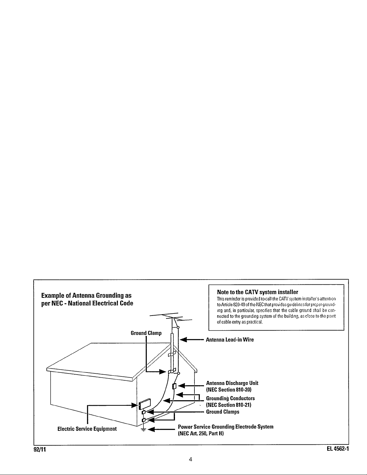
15. Outdoor Antenna Grounding • If an outside antenna is connected to the
receiver, be sure the antenna system is grounded so as to provide some
protection against voltage surges and built up static charges.
Section 810 of the National Electrical Code, ANSI/NFPA No. 70-1984, provides
information with respect to proper grounding of the mast and supporting
structure, grounding of the lead-in wire to an antenna discharge unit, size of
grounding connectors, location of antenna-discharge unit, connection to
grounding electrodes, and requirements for the grounding electrode. See
Figure below.
16. Nonuse Periods - The power cord of the appliance should be unplugged
from the outlet when left unused for a long period of time.
17. Object and Liquid Entry - Care should be taken so that objects do not fall
and liquids are not spilled into the enclosure through openings.
Damage Requiring Service - The appliance should be serviced by qualified
18.
service personnel when:
A. The power supply cord or the plug has been damaged; or
Objects have fallen, or liquid has spilled into the appliance; or
B.
The appliance has been exposed to rain; or
C.
The appliance does not appear to operate normally or exhibits a marked
D.
change in performance; or
The appliance has been dropped, or the enclosure damaged.
E.
19. Servicing - The user should not attempt to service the appliance beyond
that described in the operating instructions. All other servicing should be
referred to qualified service personnel.
Page 5

Welcome
This owner’s manual is designed for you. It is divided into four sections, “Getting Started,” “Operations,” “Remote Control Setup,”
and “General Information.”
The “Getting Started” section guides you through what you need to know to get your Audio Home Theatre System up and running.
The “Operations” section takes you through more advanced features, building on what you’ve done in “Getting Started.”
The “Remote Control Setup” section helps you set up your remote control to operate your other AudioAtideo equipment, such as a
CD Player, TV, and VCR.
The “General Information” section is there if you should need the information.
Remember, you can’t hurt your Audio Home Theatre System by following these instructions. So, read on... and relax!
Table of Contents
Getting Started
Features....................................................................................................................................................................................................6
Quick Use Guide:
Introduction/Supplied Accessories...............................................................................................................................................7
Hookup.......................................................................................................................................................................................8-9
Setup: Reciever/Subwoofer.........................................................................................................................................................10
Rear Panel Connections....................................................................................................................................................................11-12
Front Panel Controls/Connection................................................................................................................................................... 13-14
Installing Batteries in Remote Control..................................................................................................................................................15
Remote Control Description.............................................................................................................................................................15-16
Front Panel Display Description............................................................................................................................................................17
Operations
Amplifier:
Power ON/OFF, Balance,
Function Select, Preset Equalizer................................................................................................................................................18
Surround Sound;
ON/OFF, Mode Selection, Test Tone................................................................................;....................................................19-22
Tuner:
Auto, Manual, Direct,
Preset Memory, Recall...........................................................................................................................................................23-24
Additional Features:
Clock Set, Sleep, Wake Up, Demo.............................................................................................................................................25
Remote Control Setup
Direct Entry............................................................................................................................................................................................26
Search.....................................................................................................................................................................................................27
Additional Functions........................................................................................................................................................................28-29
Brand Codes......................................................................................................................................................................................30-35
General Information
Tips If Something Isn’t Working...........................................................................................................................................................36
Glossary................................................................................................................................................................................................. 37
Specifications.........................................................................................................................................................................................38
Warranty.................................................................................................................................................................................................39
5
Page 6

Featui^es
Your new AudioA^ideo Home Theatre System consists of an MX920AHT high-quality Receiver and five speakers. The
MX920AHT is not only a decoder of Dolby Pro Logic material for the Home Theatre process, it is also an Amplifier for your
other audio equipment such as a CD Player or Audio Cassette Deck.
Dolby Pro Logic Processor with Normal/Wide/Phantom modes. A Test Tone feature enables you to check volume levels of the
front, center, and rear speakers.
l\iner, AM/FM Stereo with Automatic or Manual Tuning, Direct Tuning, and 24 Presets.
Inputs, one AJV Input and two Audio-only Inputs (including one Input on the firont panel.)
Universal Remote Control with 36 keys, operates most brands of TVs, VCRs, Cable Controllers, CD Players, and Laser Disc
Players.
Multi-Function Display shows Function, Station Tuning, Surround Sound mode. Graphic Equalizer mode, and time.
Timer system automatically turns unit off, and features a Voice Fade In/Out.
Speaker System, designed for the acoustical diversity of Home Theatre sound, includes two Front Speakers, two Surround
Speakers, a Center Charmel Speaker, and a Subwoofer.
WARNING: TO PREVENT FIRE OR SHOCK HAZARD DO NOT EXPOSE THIS UNIT TO RAIN OR
EXCESSIVE MOISTURE.
IF YOU HAVE QUESTIONS REGARDING HOOKUP
OR OPERATION, CALL
THE PHILIPS INFORMATION
CENTER AT
1-800-531-0039.
Copyright © 1996 Philips Consumer Electronics Company.
All rights reserv'ed.
Page 7
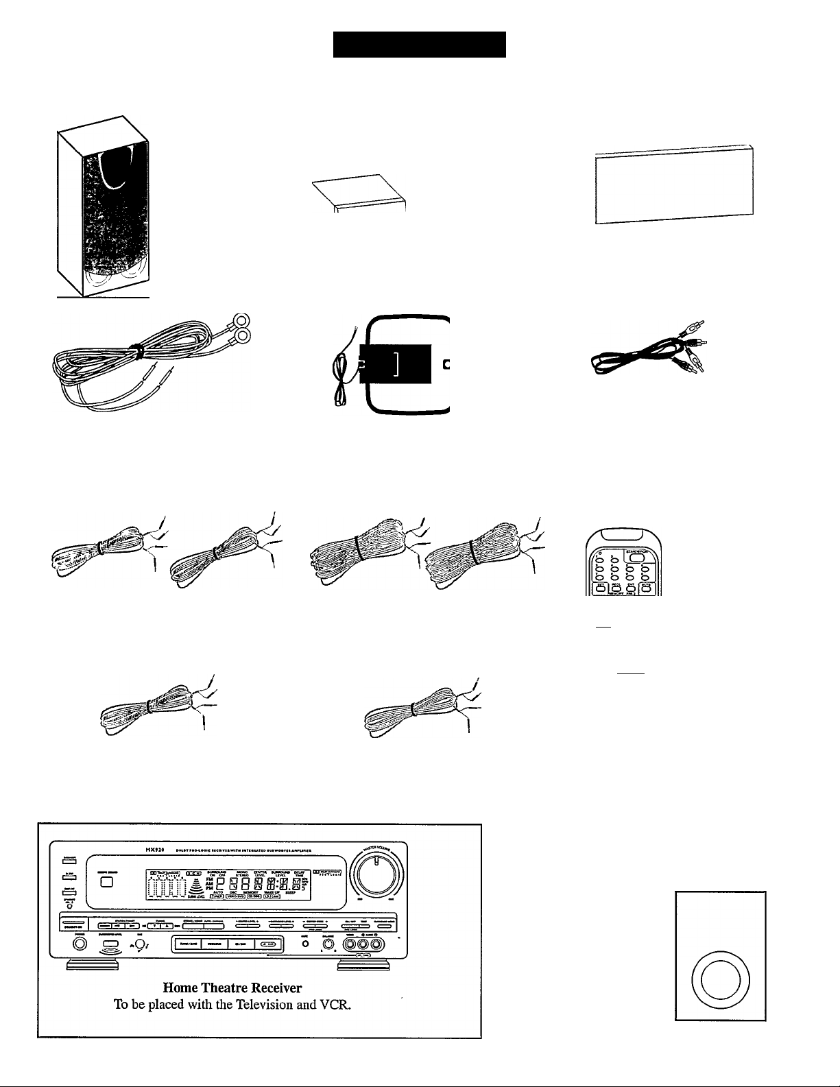
Your Home Theatre System includes the following items:
uiCK Use GuroE
Front Left and
Right Speakers
To be placed to
the left and
right of the
Television and
aimed toward
the viewing
area.
FM Antenna
Connects to the Home Theatre
Receiver for reception of FM radio
stations.
Surround
Left and
Right
Speakers
To be placed
behind and
aimed toward
the viewing
area.
AM Anteima
Connects to the Home Theatre
Receiver for reception of AM radio
stations.
Center Speaker
To be placed on top, below or at the
front of the Television and aimed
toward the viewing area.
Red- and White-Tipped Phono
Plug Coimectors:
Use to connect the VCRs left and right
“AUDIO OUT” jacks to the Home
Theatre Receiver’s left and right
“AUDIO IN” jacks.
Speaker Wire - Black and Red color
For hookup of the Main Speakers to
the Home Theatre Receiver.
Speaker Wire - Black and Blue color
For hookup of the Center Speaker to the
Home Theatre Receiver.
Speaker Wire - Black and Gray color
For hookup of the Surround Speakers to
the Home Theatre Receiver.
Speaker Wire - Black and Green color
For hookup of the Subwoofer to the
Home Theatre Receiver.
Subwoofer
To be placed to the
left or right of the
Television and
aimed toward the
viewing area.
6 a
v.i„>
СЛГЗ
Remote Control
This remote
control will
operate your
Home Theatre
Receiver.
cb SI
Page 8
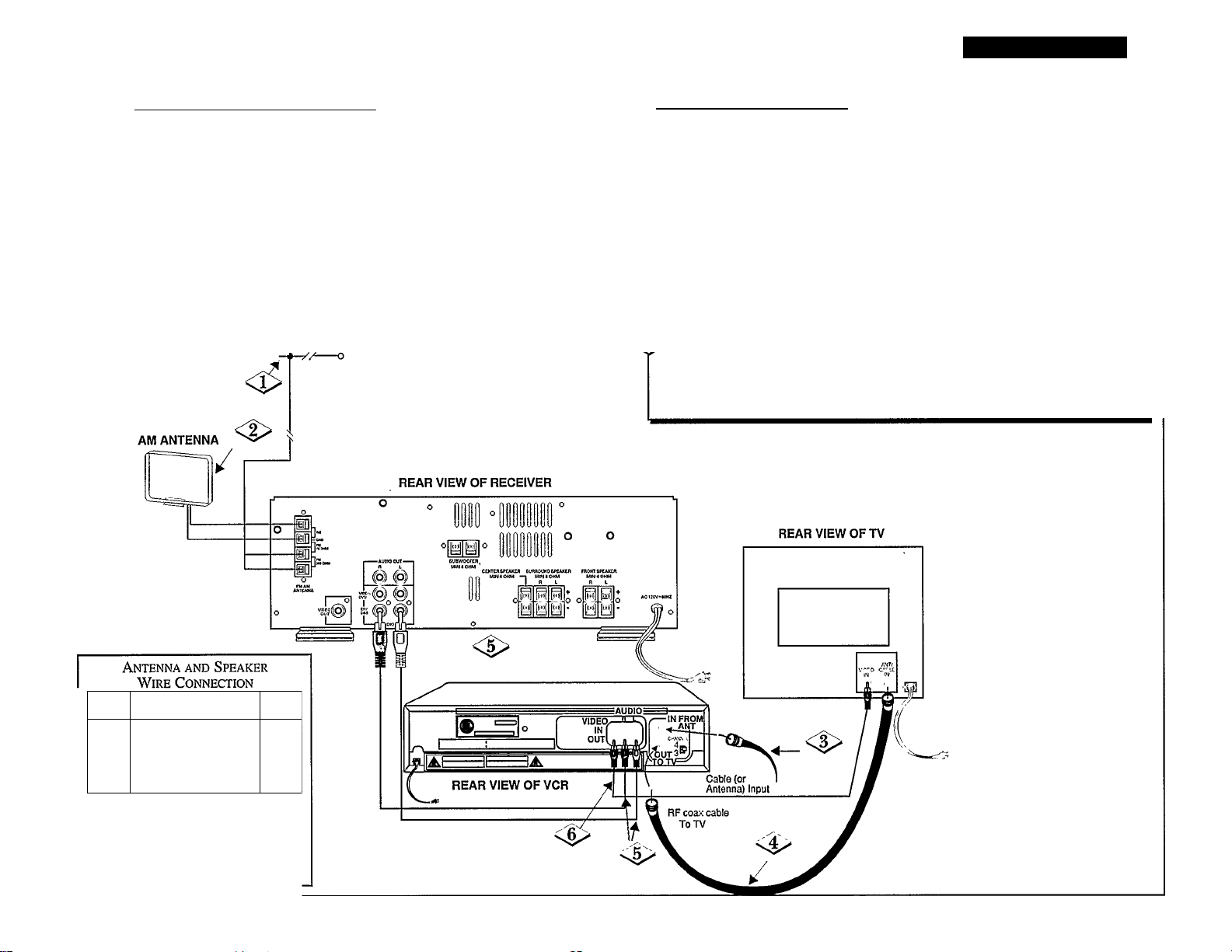
Getting Started
ANTENNA Hookup Instructions
Connect the Antennas to the Home Theater Receiver:
Connect the two ends of the FM Antenna to the Home
Theatre Receiver’s “300 ohm FM’’ terminals.
Connect the two ends of the AM Antenna to the Home
Theatre’s “AM” terminals.
NOTES; The FM Antenna should be positioned so that it is
completely spread out. The AM Antenna can be mounted by
pressing the Antenna into the AM Antenna Clip on the back
of the Receiver.
FM ANTENNA
о
----
VCR Hookup Instructions
If the VCR is already properly connected to the TV, skip to step 5:
Connect the Cable (or Antenna) to the VCR’s “IN FROM ANT” input.
With an additional R.F. Cable (usually supplied with VCR), connect
the VCR’s “OUT TO TV” to the Television’s “ANT/CABLE” input.
t
Connect the Hi-Fi VCR to the Home Theatre Receiver:
With the red and white tipped phono plug connectors (supplied), connect
the VCR’s left and right “AUDIO OUT” jacks to the Home Theatre
Receiver’s left and right “VCR/TAPE IN” audio jacks.
If your TV has an AUX(illary) VIDEO INPUT, you can connect the
VCR’s video signal to your TV as follows:
^ Using an additional phono plug (not supplied), connect the VCR’s
“VIDEO OUT” jack to the TV’s AUX(illary) “VIDEO IN” jack.
NOTES; For TV hookup and operation details, refer to your TV’s owner’s manual.
The VCR can be placed on top of the Home Theatre Receiver.
1Ж!
w
Ы
s
NOTE; Push and hold Speaker terminal
tab down to insert wire. Release tab to
lock wire in terminal. Make sure the
insulation is completely removed from
the ends of the Antenna and Speaker
wires at all connection points.
s
Page 9
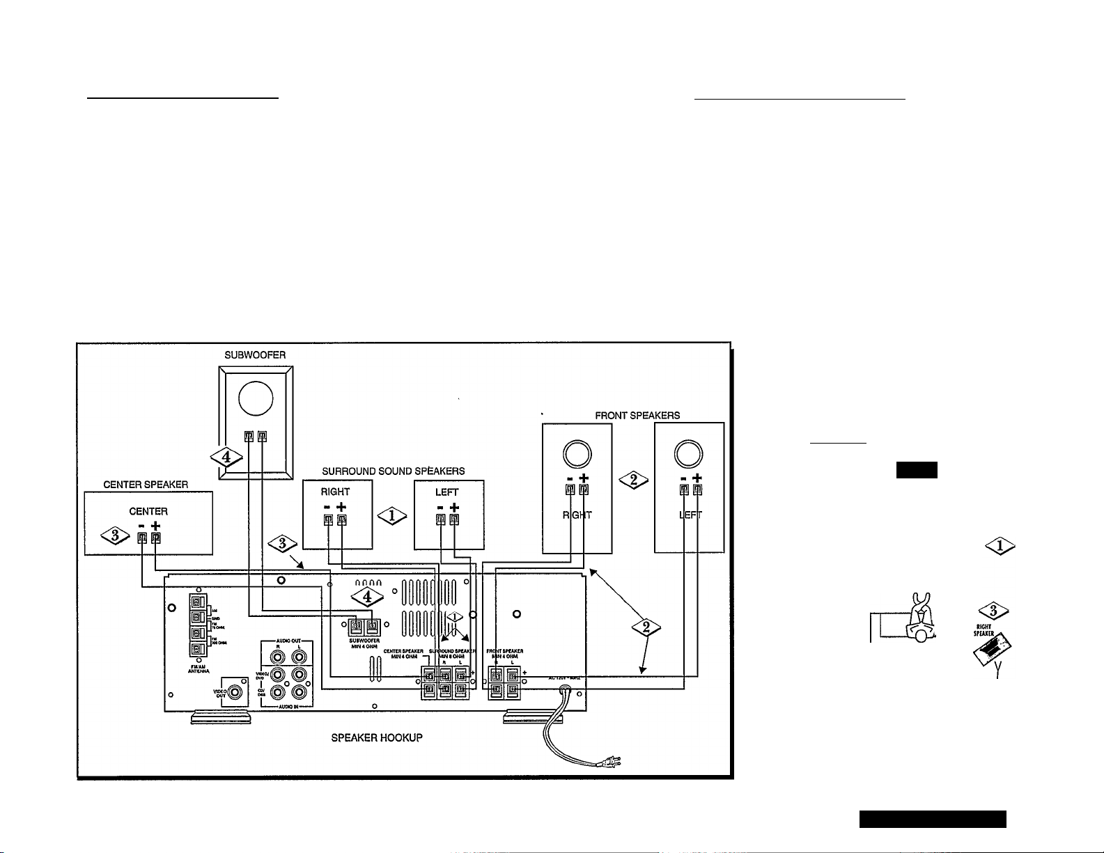
Speaker Hookup Instructions
Connect the Speakers to the Home Theatre Receiver:
Wth the two Black and Gray color speaker wire, connect the Surround Speakers to the Home Theatre
Receiver’s “SURROUND SPEAKER” terminals.
I
<i>
<P
Using the Black and Red color speaker wire, connect the Front Left and Right Speakers to the Home
Theatre Receiver’s “FRONT SPEAKER” terminals.
Using the Black and Blue color speaker wire, connect the Center Speaker to the Home Theatre
Receiver’s “CENTER SPEAKER” terminals.
Using the Black and Green color speaker wire, connect the Subwoofer Speakers to the Home Theatre
Receiver’s “SUBWOOFER” terminals.
NOTE: Be sure the (+) and (-) speaker wires are connected to the correct R(ight) and L(eft) Speaker terminals on
the Home Theatre Receiver.
Speaker Positioning Instructions
Place the Front Left Speaker to the left of the
Television as seen from the front of the Television.
Place the Front Right Speaker to the right of the
Television as seen from the front of the Television.
Place the Center Speaker on top, below, or at the
front of the Television.
<l>
<3>
Place the Surround Speakers behind and aimed
toward the viewing area. The viewing area should
be between the Television and the Surround
Speakers.
Place the Subwoofer to the left or right of the
Television as seen from the front of the Television.
<|>
SURROUND
rsu
RKOKTSPUK» OUTPUT
OKHR SHAKER OUTPUT
I rROHTSPlAKER OUTPUT
m
UFTTROKT TEltVISlOH RIGHT FRONT
SPUXER SPUR»
<l>
UFT
SPEAKER
<l>
Y
NOTE: If you hear a buzz from the Front Speakers,
move them farther away from the TV.
SURROUHD SOUND SPEAKEtS
aaiRvxs DNiiiao
Page 10
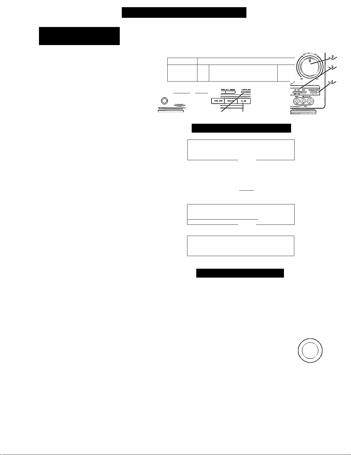
uicK Use Guidé (continued
4>
<>
4>
Audio Home Theatre
Receiver Operations
NOTE: The steps listed here describe
how to operate your Receiver using the
controls found on the front panel of the
Receiver. For remote control details, see
page 15.
Plug the AC power cord into a
standard household 120V A.C. outlet.
The STANDBY LED will come on.
Press the STANDBY-ON button. The
Receiver will turn on. The STANDBY
LED will turn off.
Select the Source. Press the
“VIDEO/DVD” SOURCE
SELECTOR button. “VIDEO/DVD”
will appear in the Receiver’s display.
Press the SURROUND MODE button
until “SURROUND ON” appears in
the Receiver’s display.
Press the PRO LOGIC button. The
“DOLBY SURROUND PRO LOGIC”
trademark will appear in the display.
Press either the PROLOGIC CENTER
MODE (+) or (-) button until
“NORMAL” appears in the display.
Play a Dolby Pro Logic encoded
videotape in your Hi-Fi VCR. Make
sure your Television’s volume is
completely mrned down. Now, adjust
the Receiver’s MASTER VOLUME
knob to a normal listening level.
Adjust the Surround (or rear) volume
by pressing the SURROUND LEVEL
(+) or (-) button until the rear sound
can be heard when playing a Dolby
Prologic encoded videotape in your
VCR.
ff you have questions regarding hookup or operation, call the Philips
Information Center at 1-800-531-0039.
<î>-
<l>-
r
L^|.^ , .wIh.1^ 1 * i-l
MX9Z0 Doi»Tri
—— £ 53 O O O ® 621^
: Lil U lii}
J ^ __ese wmse? star
[«With IHTICtATID tvltweftfO AKMIftti
—rrvn svasocNO MONO etvfr« mokoo ccut
If V on cn sn.«£0 U.tl ur.lt rM
e -0/
<§> 's§>
i Receiver Display Screens
SURROUND
OFF
1
L L 1 1
r 1 (
'■=i ■=> c=>
w WW m ^
.-2—
«ï 'VIF.Tl |VOCO OVD}
1
4>
<i>
4>
~ M M •• £L“.Vir.tt
rrUnS^lSSiSI SURROUND
«OOHi ON
». ^ ». tM ». !5?r.Vir.71 1 VK>CO DVO|
Subwoofer Operations
The sound level of the Subwoofer can be SUBWOOFER
adjusted to your desired level. For details, see
page 17.
NOTE: At lower sound levels, the bass sound may not
be as clearly heard. This is normal
MHO lï// o I
I M U I ' /MIL
I VTDtO oTol
1
SUffiOUNO SURROUND
r 1 1
~ ^ ^ IVTDCOO.TJl
1
_! U U
CENTER
u\-u
C _( l_
_l u u
4>
Adjust the Center volume by pressing
the CENTER LEVEL (+) or (-) button
until the center sound can be heard
when playing a Dolby Prologic
encoded videotape in your VCR.
NOTES: The sound from the Surround
Speakers and the Center Speaker should be
suffidiently heard, but it should not be as loud
as the sound from the front speakers.
For Surround Sound details, see pages 19-22.
It is recommended to adjust the volumes of the
center and rear sound at a normal listening
level
10
Page 11
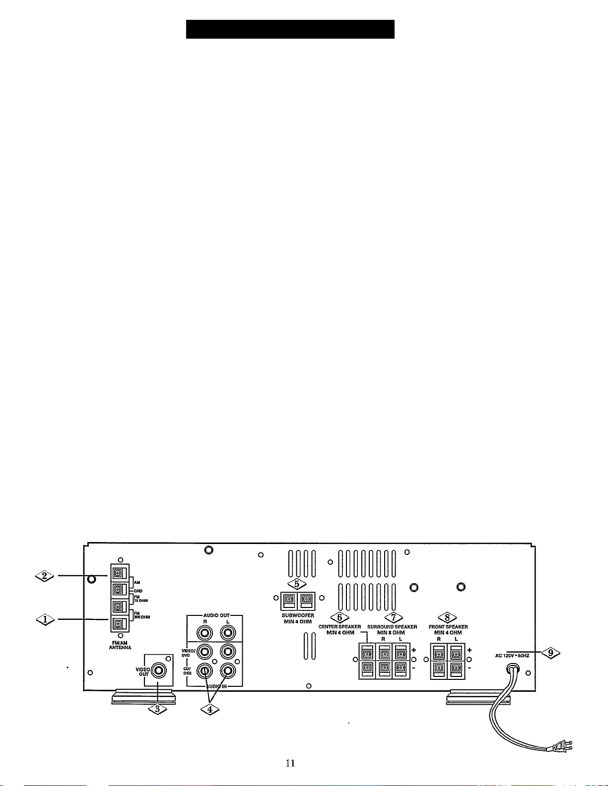
Rear Panel Connections
<2>
FM ANTENNA
75 ohm - Hookup an outside FM 75 ohm
antenna here.
300 ohm - If you do not have an outside
antenna, hookup your supplied FM antenna
here.
AM ANTENNA
Hookup your supplied AM antenna here.
For details, see page 8.
VIDEO jacks
• VIDEO OUT - For hoolcup to the video input of
a VCR. This will allow you to record on your
VCR the video currently selected on the Home
Theatre Receiver.
-ORFor hookup to the video input (or AUX IN) of a
TV set. By switching the TV to “AUX IN,” you
can view the video currently selected on the
Home Theatre Receiver.
AUDIO jacks (Left/Right)
• AUDIO OUT - For hookup to the audio
inputs of a VCR or Audio Cassette Deck. This
will allow you to record the audio currently
selected on the Home Theatre Receiver.
• VIDEO/DVD - For hookup to the outputs of a
VCR, DVD or TV. This will allow you to listen
to a VCR, DVD or listen to the TV through
your Receiver. For details, see pages 12 and 18.
• CD/DSS - For hookup to the outputs of a CD,
Audio Cassette Deck or Digital Satellite
System. This will allow you to listen to an
audio cassette, CD or DSS.
For details, see pages 12 and 18.
SUBWOOFER (4 ohm)
Connect your supplied Subwoofer here.
For details, see page 9.
<|> CENTER SPEAKER (4 ohm)
Connect your supplied Center Speaker here.
For details, see page 9.
SURROUND SPEAKERS (8 ohm)
Connect your supplied Left and Right Surround
Speakers here. For details, see page 9.
<8> FRONT SPEAKERS (4 ohm)
Connect your supplied Left and Right Front
Speakers here. For details, see page 9.
<|> POWER CORD
[AC (Alternating Current)]
Plug into a standard 120V/60Hz household wall
outlet. For details, see page 10.
Page 12
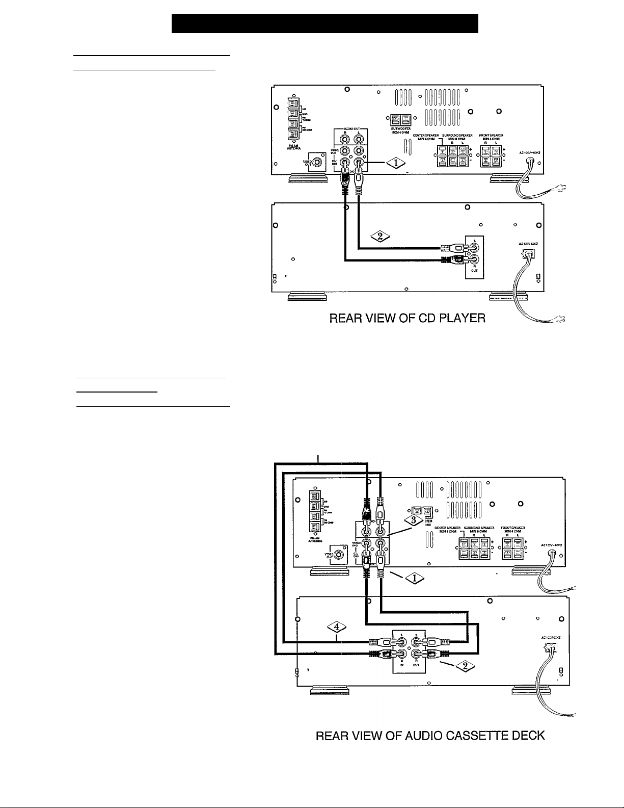
Rear Panel Connections (continued
A CD Plaver can be connected to
vour Home Theatre Receiver:
NOTE: Make sure the left OUTPUT is connected to
the left INPUT, and the right OUTPUT is eonnected
to the right INPUT.
Locate the CD/DSS AUDIO IN jacks
I on the rear panel of the Receiver.
Using phono plugs (not supplied),
connect the CD Player’s L/R OUT to
the CD/DSS AUDIO IN jacks on the
Receiver.
REAR VIEW OF RECEIVER
A VCR or Audio Cassette Deck
can be connected
to vour Home Theatre Receiver;
NOTE; This hookup will allow the Audio Cassette
Deck or VCR to both record and playback through
the Receiver.
Locate the VEDEO/DVD AUDIO IN
jacks on the rear panel of the Receiver.
I
<s >
<s >
Using phono plugs (not supplied),
connect either the Audio Cassette
Deck’s or the VCR’s L/R OUT to the
VIDEO/DVD AUDIO IN jacks on the
Receiver.
Locate the AUDIO OUT jacks on the
rear panel of the Receiver.
Using phono plugs (not supplied),
connect either the Audio Cassette
Deck’s or the VCR’s L/R IN to the
AUDIO OUT jacks on the Receiver.
NOTES: Connection of Audio Cassette Deck to
Receiver is shown. For hookup details of VCR to
Receiver, see page 8.
<S> REAR VIEW OF RECEIVER
A VCR and Audio Cassette Deck cannot be
connected to this Receiver at the same time.
By connecting the Receiver’s AUDIO OUT UR and
the VIDEO OUT to the AUDIO and VIDEO inputs
on a VCR, you can record on the VCR what is
connected to the Receiver’s front LD/CAM inputs.
12
Page 13
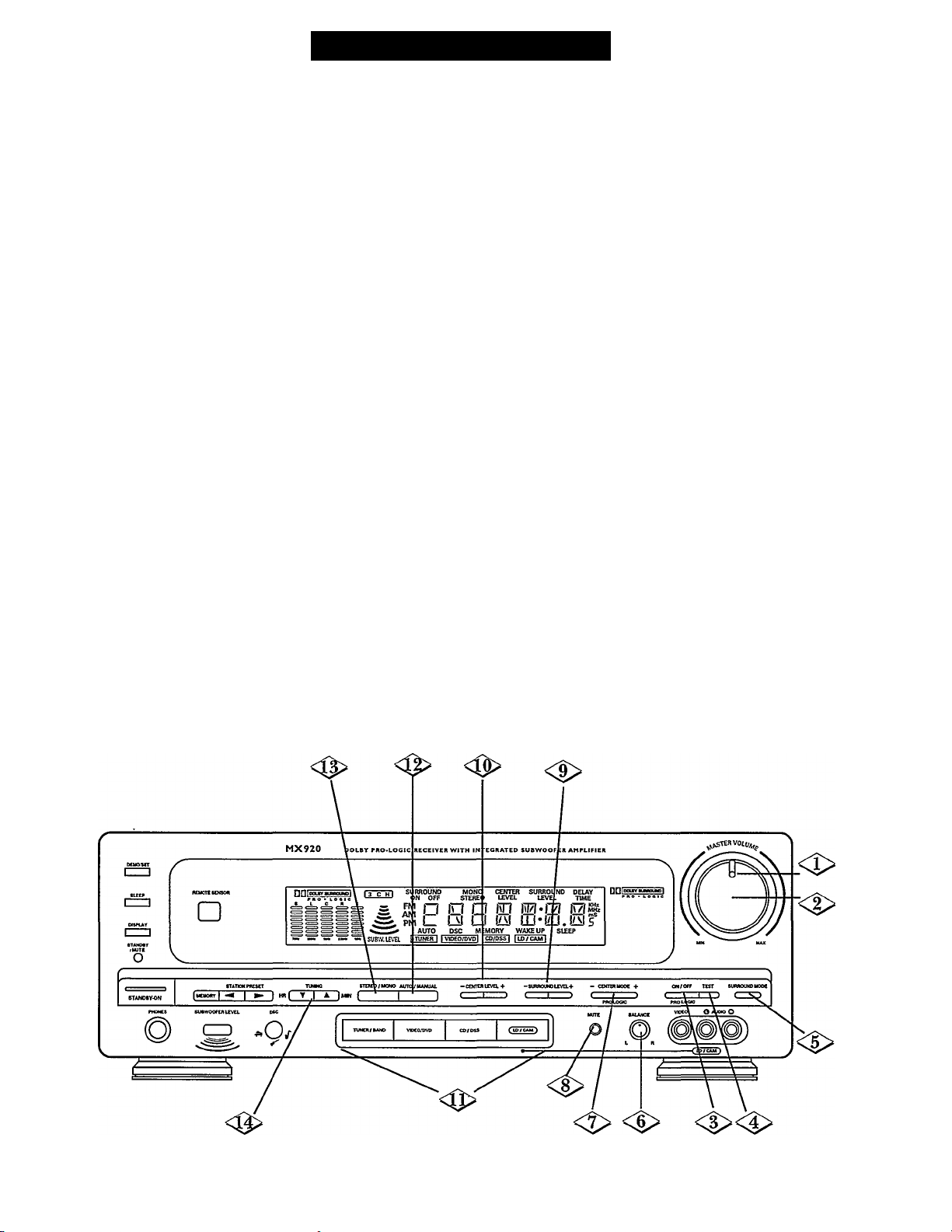
Front Panel Controls
<J> VOLUME LEVEL INDICATOR
LED lights when Receiver’s power is on.
<|> MASTER VOLUME control
'Him this knob to adjust the sound level up
and down. For details, see page 18.
NOTE: When Surround Mode is on, the MASTER VOLUME
controls the overall sound level of all speakers. When Surround is
off, the MASTER VOLUME controls the Front Left and Right
Speakers’ and the Subwoofer's sound level.
<$> PRO LOGIC
Press to turn DOLBY PRO LOGIC on.
For details, see pages 19-22.
TEST
Press to begin the TEST TONE mode. Press again
to stop the test. For details, see pages 19-22.
<|> SURROUND MODE
Press to turn the SURROUND MODE on and off.
For details, see pages 19-22.
<|> BALANCE (L/R)
Turn this knob to adjust the balance of sound
coming from the Front Left and Right Speakers.
For details, see page 18.
<7> PRO LOGIC CENTER MODE (+/-)
Press the (+) or (-) button to select NORMAL,
WIDE or PHANTOM.
For details, see pages 19-22.
<|>MUTE
Press to turn the sound off. Press again to return
the sound to its previous level. The STANDBY/
MUTE LED will flash when MUTE is on.
<9> SURROUND LEVEL (+/-)
Press the (+) or (-) button to adjust the Left and
Right Surround Speakers’ relative sound level up
and down. For details, see pages 19-22.
CENTER LEVEL (+/-)
Press the (+) or (-) button to adjust the Center
Speaker’s relative sound level up and down. For
details, see pages 19-22.
<0> SOURCE SELECTOR (TUNER/
BAND, VIDEO/DVD,CD/DSS,
LD/CAM)
Press to select the desired mode. For details,
see page 18. You can also turn the Receiver on by
pressing a SOURCE SELECTOR button.
AUTO/MANUAL
Press to select either AUTO or MANUAL (AM/FM)
tuning mode. For detaih, see pages 23-24.
STEREO/MONO
Press to select either ST(ereo) or MONO sound.
TUNING (T/A)
Press the
select an AM/FM station. For details, see pages
23-24. Also, use these buttons to set the clock.
For details, see page 25.
(T)
“down” or
(A)
“up” button to
13
Page 14
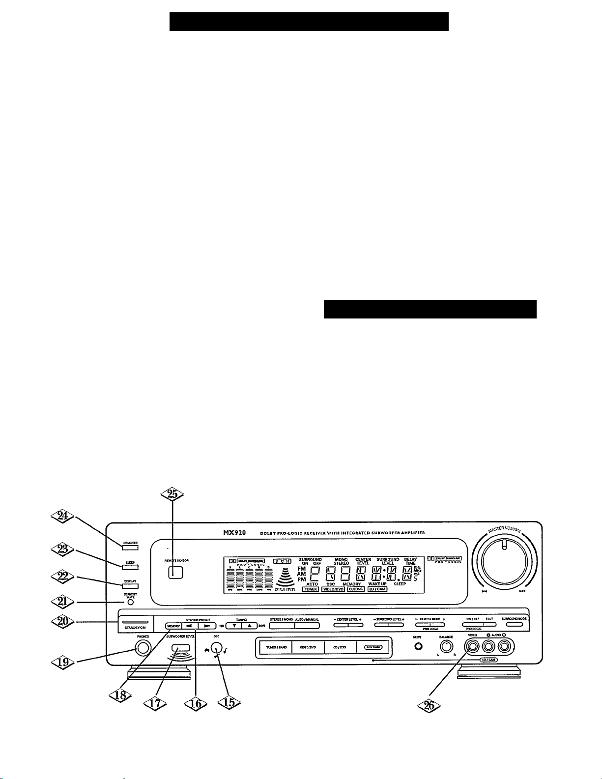
Front Panel Controls (continued
DSC
Press to select a PRESET EQUALIZER mode
(JAZZ, CLASSIC, ROCK, or POP).
For details, see page 18.
STATION PRESET (◄/►)
Press the (-^) or (►) button to select a preset
station. For details, see page 23-24.
<Q> SUBWOOFER LEVEL
Press to cyclic adjust the SUBWOOFER LEVEL
up or down.
For details, see page 18.
MEMORY
Press to store AM/FM stations in memory.
For details, see pages 23-24.
<0> PHONES
Plug in your Headphones here. Use the MASTER
VOLUME control to adjust the Headphones
sound level.
NOTE: When Headphones are plugged into the
Receiver, no sound will come from the Speakers.
STANDBY-ON
Press to turn the Receiver on. Press again to
turn the Receiver off.
STANDBY/MUTE LED
This LED will light up when the Receiver is
plugged into a household wall outlet. When the
Receiver is turned on, the STANDBY LED will
become brighter. Also, the LED will flash when
the Receiver is in the MUTE mode.
DISPLAY
Press to change the Receiver’s display from
CLOCK SET mode, SLEEP mode, WAKE UP
mode, to TUNER mode. For details, see page 25.
SLEEP
Press this button to select the SLEEP mode.
For details, see page 25.
DEMO/SET
Press to start a DEMO(nstration) mode. Press
any button to stop the Demonstration.
This button is also used to adjust the SLEEP
and WAKE UP times. For details, see page 25.
Also, this button is used to select a 12-hour or
24-hour CLOCK display. For details, see page 25.
REMOTE SENSOR
Receives the signal from the (wireless) remote
control.
Front Panel Connections
LD/CAM INPUT
For hookup to the VIDEO and L/R AUDIO
outputs of a Camcorder or other AudioWideo
component.
NOTE: To hook up a Laser Disc Player or Camcorder to
this input, simply connect the VIDEO OUT and AUDIO
OUT(s) of the equipment to the VIDEO and L/R AUDIO
inputs on the Receiver. Turn the Receiver on by pressing the
POWER button and then press the LD/CAM SOURCE
SELECTOR button.
14
Page 15
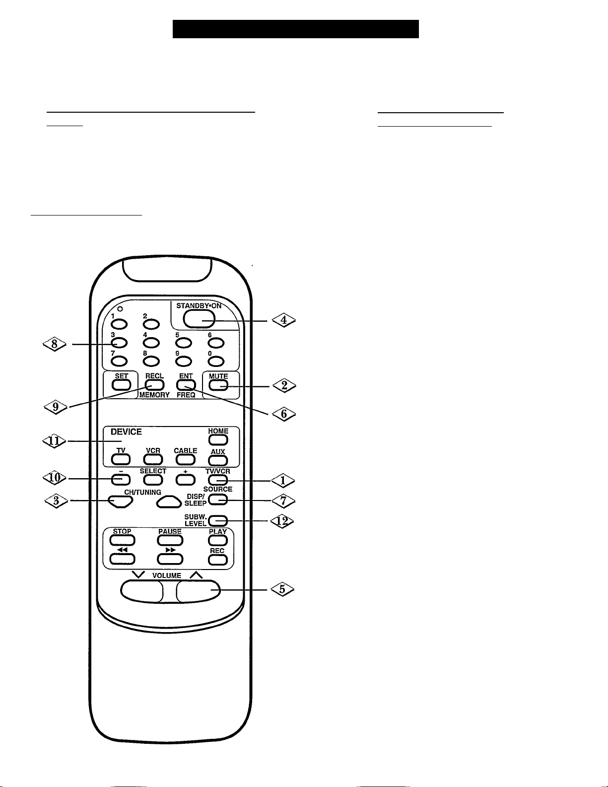
Remote Control Description
Your Home Theatre Receiver’s remote control will not only operate your Receiver but will also operate many brands of
infrared-controlled TVs, VCRs, and Cable Controllers. Many CD Players, or Laser Disc Players, or Audio Cassette Decks can
be controlled as well. For details, see pages 26 through 32.
To load the supplied batteries into the remote
control:
<^1^ Remove the Battery compartment lid on the back of
I the remote.
Place the 2 AAA batteries in the remote. Be sure to
line the (+) and (-) ends of the batteries as indicated
inside the battery compartment.
<^3^ Reattach the battery lid.____________________________
Using your remote with the
Home Theatre Receiver:
NOTES: Be sure to first press the “HOME” button
before operating your Receiver with the remote. The
remote control will remain tuned to the “HOME”
(or Receiver) mode until another mode is chosen.
Be sure to point the remote toward the remote sensor
on the front of the Receiver.
TVA^CR, SOURCE
Press this button to select the desired
Receiver mode (TUNER, VCR, CD, etc.).
For details, see page 18.
<i> MUTE
Press to turn the sound off. Press again to
return the sound to its previous level.
<|> CH(annel)/TUNING (T/A)
Press the
Receiver is in the TUNER mode, to select
an AM/EM station. For details, see pages
23-24.
(T)
or
(A)
button, when the
<i> STANDBY'ON
Press to turn the Receiver on. Press again
to turn the Receiver off.
<|> VOLUME (V / A)
Press to adjust the sound level up and down.
For details, see page 13.
<|> ENT(er),FREQ
Press to enter a direct AM/FM station
frequency. For details, see pages 23-24.
<|> DISP/SLEEP
Press to set the SLEEP timer. For details,
see page 25.
NUMBER buttons
When the Receiver is in the TUNER mode,
press to enter a direct AM/FM station
frequency. For details, see pages 23-24.
<i> RECL, MEMORY
I Press to store AM/FM stations in memory.
I For details, see pages 23-24.
SELECT, (-/+)
Press to select the CENTER or
SURROUND levels. Press the (+) or (-)
button to adjust the selected level. For
details, see pages 19-22.
DEVICE
Press to select the desired mode (HOME,
TV, VCR, CABLE, AUX). The remote
will then control the selected equipment.
15
SUBW. LEVEL
Press to cyclic adjust the SUBWOOFER
LEVEL up or down, see page 17.
Page 16
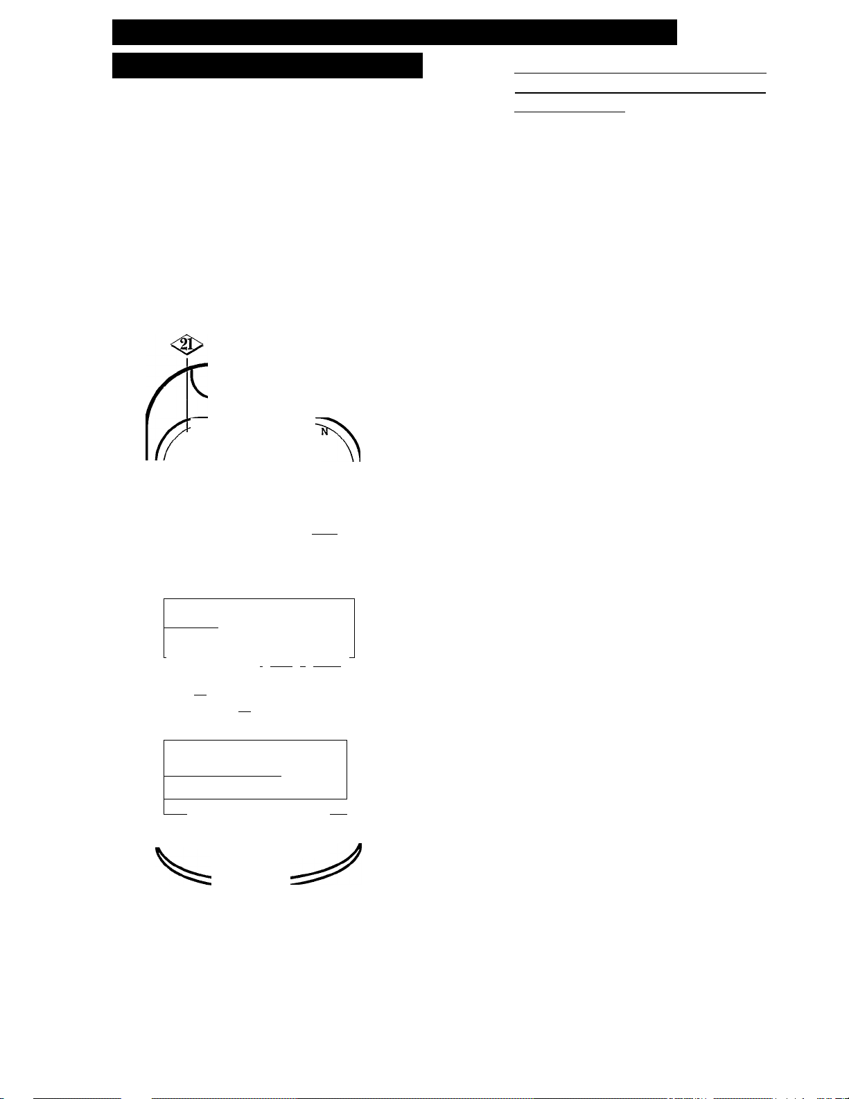
Remote Control DESCiaPTiON (continued
!! Very Important Note !!
NOTE: Always first select the desired mode (HOME, TV,
VCR, CABLE, orAUX) by pressing the MODE SELECT
button. Then, Press the desired feature button (PLAY,
SEARCH, etc.). The remote control will remain tuned to the
selected mode until another mode is chosen.
Press HOME to control the Receiver.
Press TV to control the TV.
Press VCR to control the VCR.
Press CABLE to control the Cable
Controller Box.
Press AUX to control your CD Player,
LD Player, or Audio Cassette Deck.
For details, see pages 26-32.
STANDBY-0
<0>-
1*=^ 2
o o
5-^ 5-^
o o o o
o
o o o o
SET
-o
RECL ENT
o o
MEMORY FREQ
MUTE
C3^
•<J>
Using vour remote with a TV- VCR. CABLE, or AUX (CD Player. Laser Disc Player, etc.):
^ SET
Press to “setup” your remote control
to operate your other AudioA^ideo
equipment, such as a TV, or VCR.
TVA^CR, SOURCE
Press this button when the remote is
in the VCR mode to select VCR or TV on
the VCR.
MUTE
Press to turn the sound off. Press again to
return the sound to its previous level.
<$> CH(annel)/TUNER
Press, when the remote control is in
the TV, VCR, or CABLE mode, to select
a TV channel.
(T/A)
VOL(ume)(V /A)
When the remote is in the TV mode,
press to adjust TV’s volume.
<^> NUMBER buttons
When the remote is in the TV, VCR,
or CABLE mode, use these buttons
to select a TV channel.
<1S>
DEVICE
TV VCR CABLE
o o
o
- SELECT + TVA/CR
O O O C3-
CHH-UNING SOURCE
C T SLEEP
Z' STOP PAUSE PLAY A
■« ►►
i ^ ( )
[O CD
V VOLUME
CH3
HOME
o
AUX
o
DISP//
---------
SUBW.i^^
levelA_^
o
REC
oj
VCR, TAPE FUNCTION keys
◄◄ (REWIND), PLAY, ►► (FAST
FORWARD), REC(ord), STOP, and
PAUSE.
DEVICE
<è>
\
Press to select the desired mode (HOME,
TV, VCR, CABLE, AUX). The remote
will then control the selected equipment.
LED
The LED lights up when performing the
remote control “setup.” For details, see
pages 26-27.
■O
Also, the LED flashes whenever a button is
pressed during normal remote use.
16
Page 17
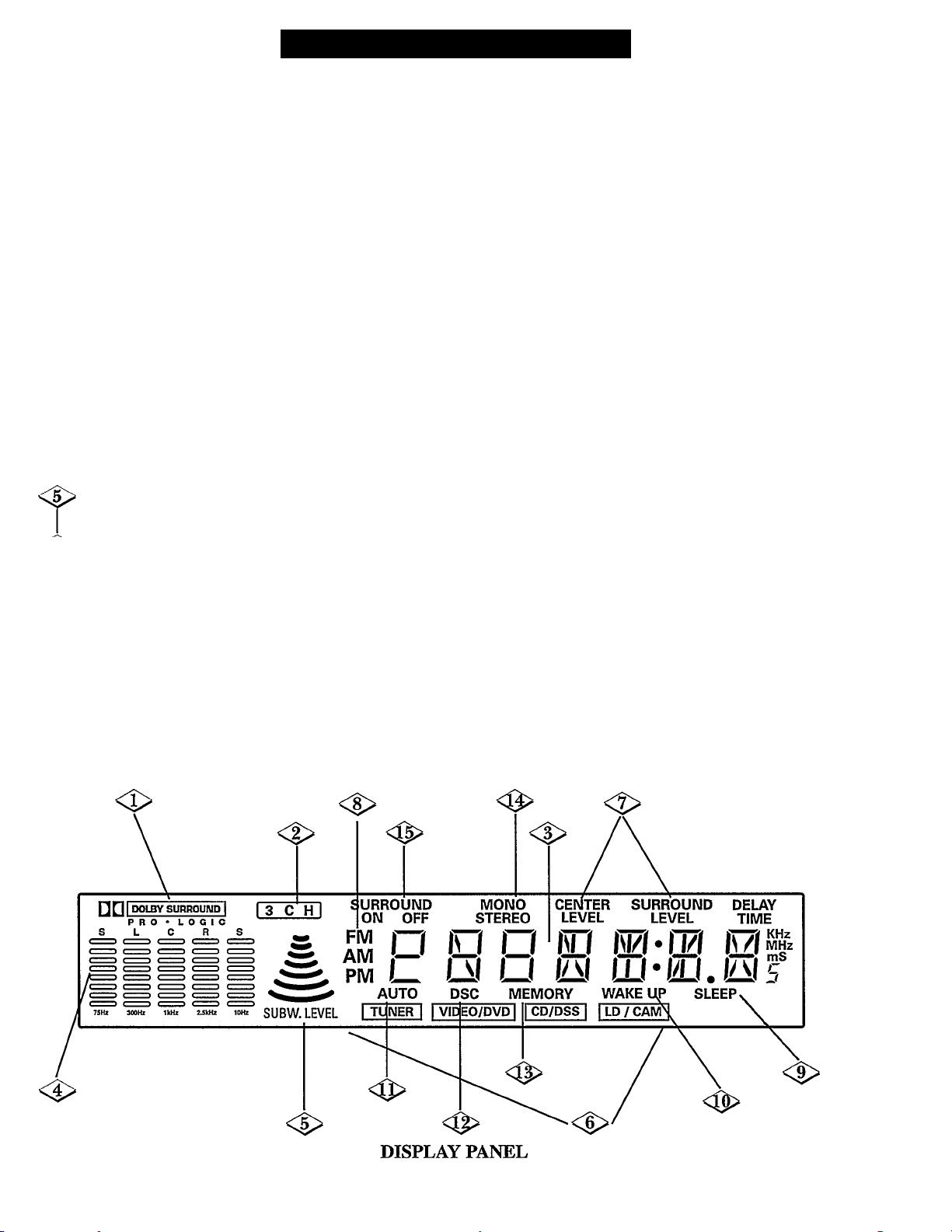
Front Display Description
<1> DOLBY SURROUND PRO LOGIC
This lights up when the DOLBY PRO LOGIC
feature is on. For details, see pages 19-22.
<|> 3CH
This lights up when the 3 CH(annel) Surround
mode is on. For details, see pages 19-22.
CLOCK/FREQUENCY
The CLOCK or AM/FM STATION is
displayed here.
EQUALIZER
<$>
The preset EQUALIZER levels are displayed
here. For details, see page 18. Also, when
using the TEST TONE feature for adjusting
speaker levels in SURROUND SOUND, each
speaker level will be displayed here. “S” stands
for SURROUND, “L” stands for FRONT
LEFT, “C” stands for CENTER, and “R”
stands for FRONT RIGHT. For details, see.
page 22.
SUBW. LEVEL
This shows the strength of the Subwoofer.
<6> SOURCE
The selected SOURCE (TUNER,
VIDEO/DVD, etc.) is shown here.
<|> CENTER LEVEL,
SURROUND LEVEL
These will light up when adjusting their levels.
<t>
<t>
<5>
<P
O
< S >
<S>
<g>
FM/AM,AM/PM
This indicates the selected TUNER
waveband or CLOCK mode.
SLEEP
This lights up when the SLEEP
mode is on.
WAKE UP
This lights up when the WAKE UP
mode is on.
AUTO
This lights up when the AUTO(matic)
tuning mode is selected.
DSC
This lights up when DSC mode is on.
MEMORY
This flashes when the MEMORY
button has been pressed. For details,
see pages 23-24.
STEREO
This lights up when an FM stereo
transmission is received.
SURROUND ON/OFF
This lights up “ON” when SURROUND
is on.
17
Page 18
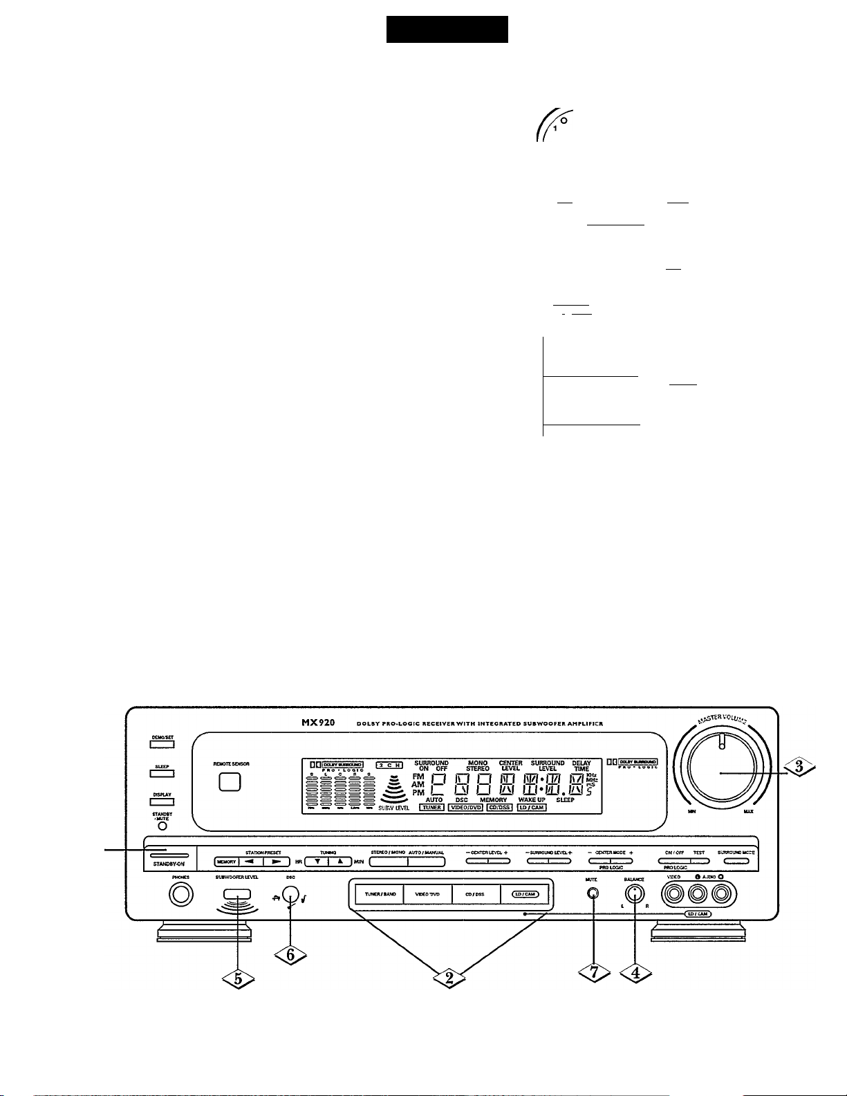
Press the STANDBY*ON button. The Receiver will turn
I on. The STANDBY LED will become brighter.
Select the Source by pressing the desired SOURCE
SELECTOR button (or, press the TV, VCR, SOURCE
button on the remote until the desired mode is selected):
Press TUNER/BAND to listen to a radio station.
Press VIDEO/DVD for a VCR or Audio Cassette Deck.
Press CD/DSS to listen to a compact disc.
Press LD/CAM for a Laser Disc Player or Camcorder.
For remote control details, see page 15-16.
NOTE: When selecting either VCRJTAPE or LD/CAM, the
connected audio source will be heard through the Speakers. The
connected video source can be viewed through a TV connected to
the TV VIDEO OUTjack located on the back of the Receiver.
<t>
<S>
<l>
<3>
Turn the MASTER VOLUME knob to adjust the overall
sound level (or, press the VOL(ume) (V / A) buttons
on the remote).
Turn the BALANCE knob to level the sound coming
from the Front Left and Right Speakers.
I
Press the SUBWOOFER LEVEL button if you want to
hear stronger low frequencies.
I
Press the DSC button to select either JAZZ, ROCK,
CLASSIC, or POP.
I
Press to turn the sound off. The STANDBY/MUTE
LED will flash. Press again to turn the sound on.
NOTES: The Graphic Equalizer separates and adjusts the bass, mid
range, and treble levels. These preset selections adjust the sound to
simulate and enhance the acoustical effects of JAZZ, ROCK,
CLASSIC, and POP.
For Surround Sound modes, see pages 19-22.
Amplifier
o o
5-^ 5-^ 5-^
o o o o
5-^ 2-^ 2-^
o o o o
SETORECL ENT
O O
MEMORY FREQ
DEVICE pijE
TV VCR CABl^ AUX
o o o o
- SELECT TV/yCR
O O O O-
CH/rUNING
r STOP
(ZD
W
PAUSE
CD
(zb
volume
____
o
MUTE
O
SOURCE
DISP/ (— \
SLEEP
SUBW.r^
leveiA-J
~playA
O
REC
O
^
■<i>
-<l>
-<l>
<i>
V.
18
Page 19
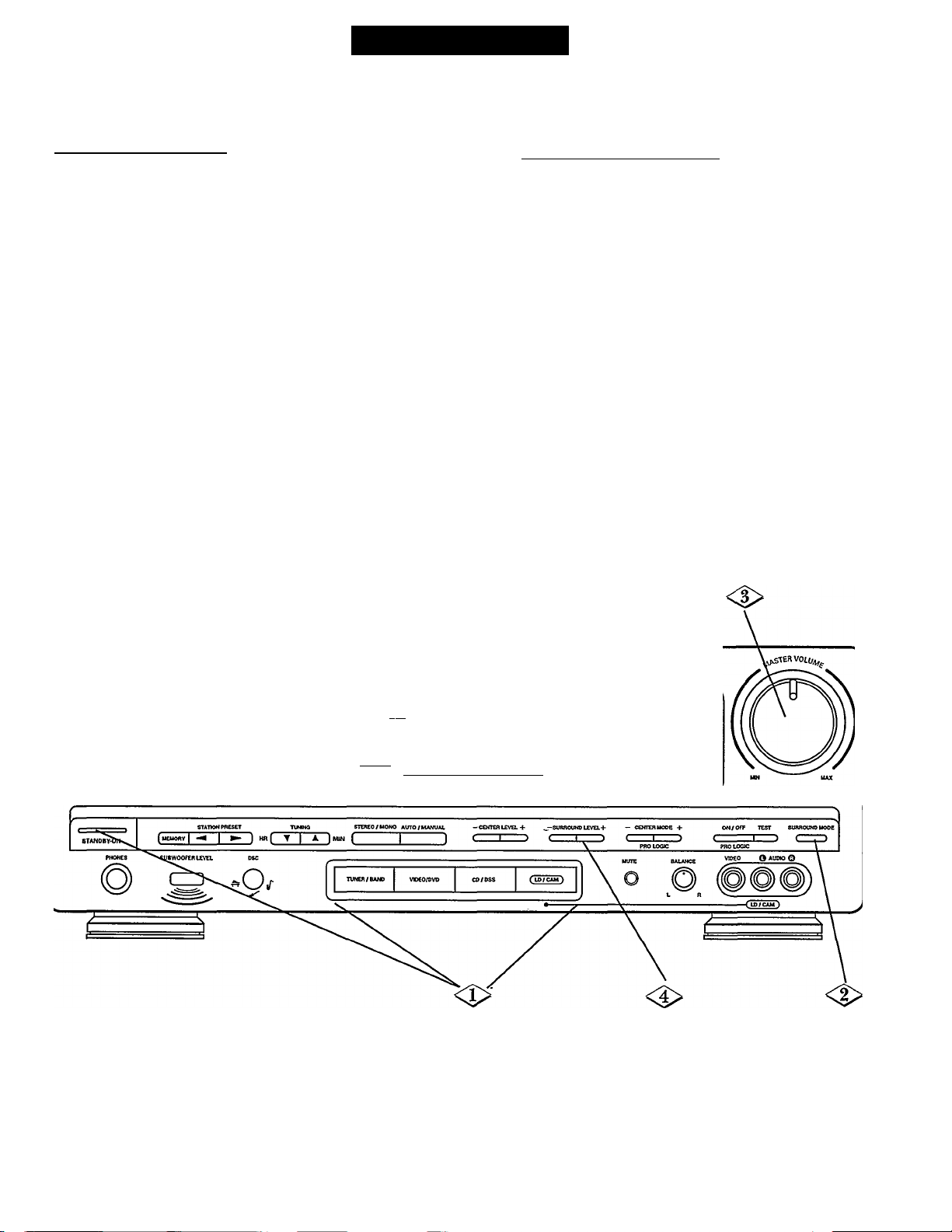
Surround Sound
Your Home Theatre Receiver gives you three Surround Sound options: Surround, Dolby Pro Logic Surround, and
Dolby Pro Logic 3CH(annel).
Surround Sound mode;
Choose this feature when playing non Dolby Pro Logic
Surround encoded movies and music. This Surround
mode gives you a feeling of being surrounded by sound.
NOTE: The Center channel (Center Speaker) is not used
in this mode.
To Select Surround Sound;
Turn the Receiver on and select the SOURCE.
I For details, see page 18.
Press the SURROUND MODE button until
“SURROUND ON” appears in the Receiver’s
display.
Adjust the Receiver’s MASTER VOLUME knob
to a normal listening level (or, press the Remote’s
VOLUME (A) or (V) buttons.)
Adjust the Surround (or rear) volume by pressing
the SURROUND LEVEL (+) or (-) button until the
rear sound can be heard. (Or, press the Remote’s
SELECT button until “SURROUND LEVEL”
appears in the display. Then, press the (+) or (-)
buttons to adjust the Surround volume.)
NOTE: The sound from the Surround Speakers should be
sufficiently heard, but it should not be as loud as the sound from
the front speakers.
DMOr'SET
nzn
MPUY
I
----
1
REUOre SENSOR
□
<l>
MX920 DOLBY PRO.LOGIC RECEIVER WITH INTEGRATED SUBWOOFER AMPLIFIER
Onrs
<3 c Hi SURROU
< ON 0
s S ^ D ID O ID D-® ID™^
I PM l_ Lil U IAI idJ-lAJ.liils
I ^ ^ AUTO DSC MEMORY WAKE UP SLEEP
^ SUBW.IEVEL I TUNER I I VIDEO/DV^ j CO/DSS I |tP/CAM|
MONO CENTER SURROUND DELAY
STEREO LEVEL LEVEL TIME
19
Page 20
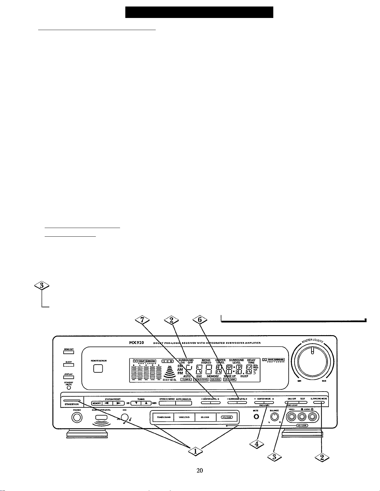
Surround Souni) (continued)
Dolby Pro Logic Surround Sound mode;
Choose this feature when playing Dolby Pro Logic
Surround encoded movies and music (especially Laser
Discs, video cassettes, and TV broadcasts with Dolby
Surround sound). Most currently-released Video
cassettes and Laser Discs and many TV broadcasts
include this feature. Not only does Dolby Pro Logic
surround you with sound, it also gives you a clear
perception of the position and direction of the sound.
You also have three Center channel options when using
the Dolby Pro Logic feature, “NORMAL,” “WTOE,” and
“PHANTOM.” These options have programmed
Surround (or delay) values for the Center channel. The
delay (or echo) effect is different in each mode:
- The NORMAL mode gives a true
Dolby Pro Logic sound.
- The WIDE mode can be used to add greater
acoustical separation of the Center Speaker.
- The PHANTOM mode diminishes the effect of
hearing a true Center channel. The Front Left
and Right Speakers give the effect of center
channel information. The Center Speaker is
actually not used.
To Select Dolby Pro Logic
Surround Sound:
> Turn the Receiver on and select the SOURCE.
For details, see page 18.
> Press the SURROUND MODE button until
“SURROUND ON” appears in the Receiver's
display.
Press the PRO LOGIC button. The “DOLBY PRO
LOGIC” trademark will appear in the display.
r
Press either the PRO LOGIC CENTER MODE (+)
or (-) button until your choice of either
“NORMAL,” “WIDE,” or “PHANTOM” appears
in the display.
If your source is a Hi-Fi VCR or Laser Disc
Player, play a Dolby Pro Logic encoded videotape
or Dolby Pro Logic encoded Laser Disc. Make
sure your Television’s volume is completely turned
down. Now, adjust the Receiver’s VOLUiV'IE knob
to a normal listening level. (Or, press the
VOLUME (A) or (V) button on the remote.)
If your source is a CD Player, play a Compact
Disc. Adjust the Receiver’s VOLUME knob to a
normal listening level. (Or, press the VOLUME
(A) or (V) button on the remote.)
NOTE: If your Compact Disc is not Dolby Pro-Logic encoded,
you may wish to try Surround Mode on without Pro-Logic,
<l>
<l>
Adjust the Surround (or rear) volume by pressing
the SURROUND LEVEL (+) or (-) button until the
rear sound can be heard when playing a Dolby
Prologic encoded videotape in your VCR. (Or,
press the remote’s SELECT button until
“SURROUND LEVEL” appears in the display.
Then, press the (+) or (-) buttons to adjust the
Surround volume.) .
Adjust the Center volume by pressing the
CENTER LEVEL (+) or (-) button until the center
sound can be heard when playing a Dolby Prologic
encoded source. (Or, press the Remote’s SELECT
button until “CENTER LEVEL” appears in the
display. Then, press the (+) or (-) buttons to adjust
the Center volume.)
NOTES: The sound from the Surround Speakers and the Center
Speaker should be sufficiently heard, but it should not be as loud
as the sound from the front speakers.
If you play a video tape which is not Dolby Surround Sound
encoded, or use a non-stereo VCR as a TV chanel tuner, or select a
non-stereo TV station when in the Pro Logic mode, you may
receive sound from only the Center Speaker.
Page 21
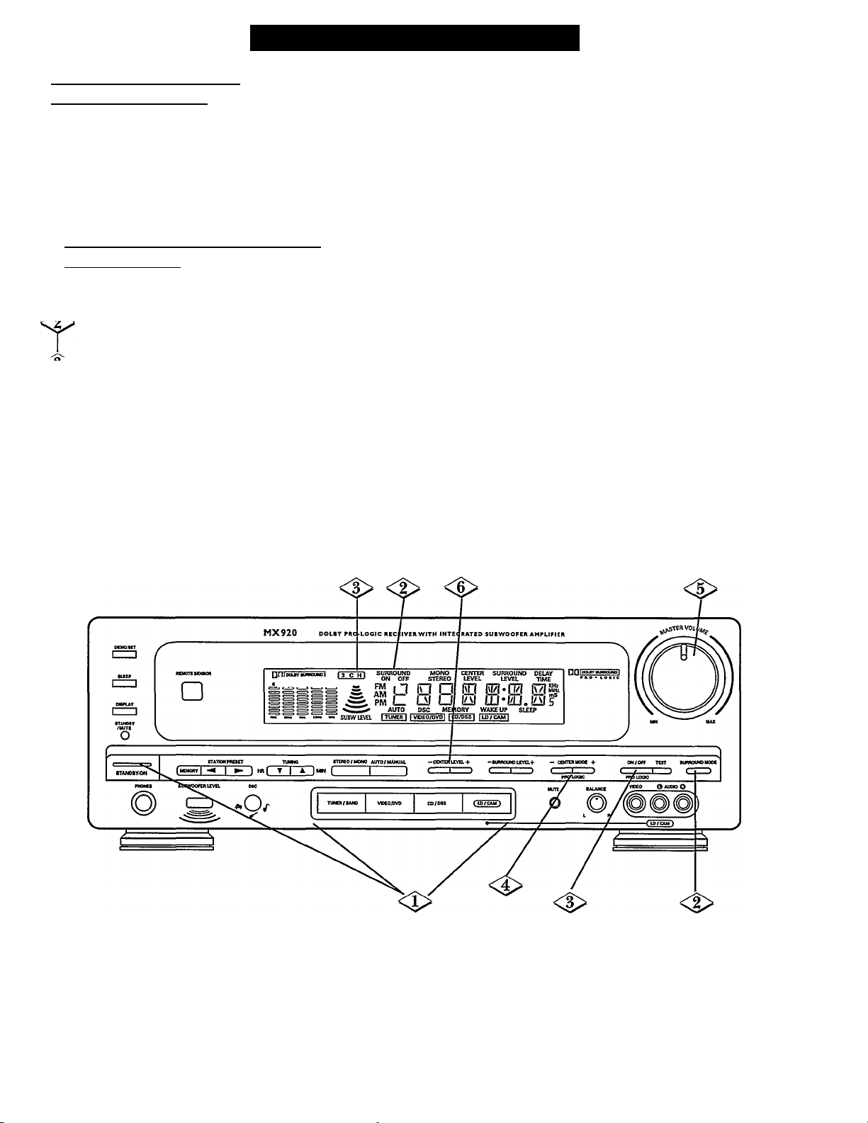
Surround Sound (continued
Dolby Pro Logic 3CHfanneli
Surround Sound mode:
Choose this feature when you wish to play Dolby Pro
Logic Surround encoded movies and music but do not
wish to use the Surround Speakers. This mode gives the
effect of Surround Sound without actually using the rear
Surround Speakers.
To Select Dolby Pro Lo^c 3 CHfanneD
Surround Sound;
Turn the Receiver on and select the SOURCE.
I For details, see page 18.
Make sure that the SURROUND MODE is not on.
“SURROUND OFF’ should appear in the display.
Press the PRO LOGIC button. “3 CH” will appear
I in the display.
Press either the PROLOGIC CENTER MODE (+)
or (-) button to select either “NORMAL” or
“WIDE.” Your selection will appear in the display.
NOTE: The “PHANTOM” Center channel mode is not available
when in the Dolby Pro Logic 3CH mode.
If your source is a Hi-Fi VCR or Laser Disc
Player, play a Dolby Pro Logic encoded videotape
or Dolby Pro Logic encoded Laser Disc. Make
sure your Television's volume is completely turned
down. Now, adjust the Receiver’s VOLUME knob
to a normal listening level. (Or, press the
VOLUME (A) or (V) buttons on the Remote.)
If your source is a CD Player, play a Compact
Disc. Adjust the Receiver's VOLUME knob to a
normal listening level. (Or, press the VOLUME
(A) or (V) buttons on the Remote.)
Adjust the Center volume by pressing the
CENTER LEVEL (+) or (-) button until the center
sound can be heard when playing a Dolby Prologic
encoded source. (Or, press the Remote’s SELECT
button until “CENTER LEVEL” appears in the
display. Then, press the (+) or (-) buttons to adjust
the Center volume.)
NOTE: The sound from the Center Speaker should be sufficiently
heard, but it should not be as loud as the soundfrom the front
speakers.
21
Page 22
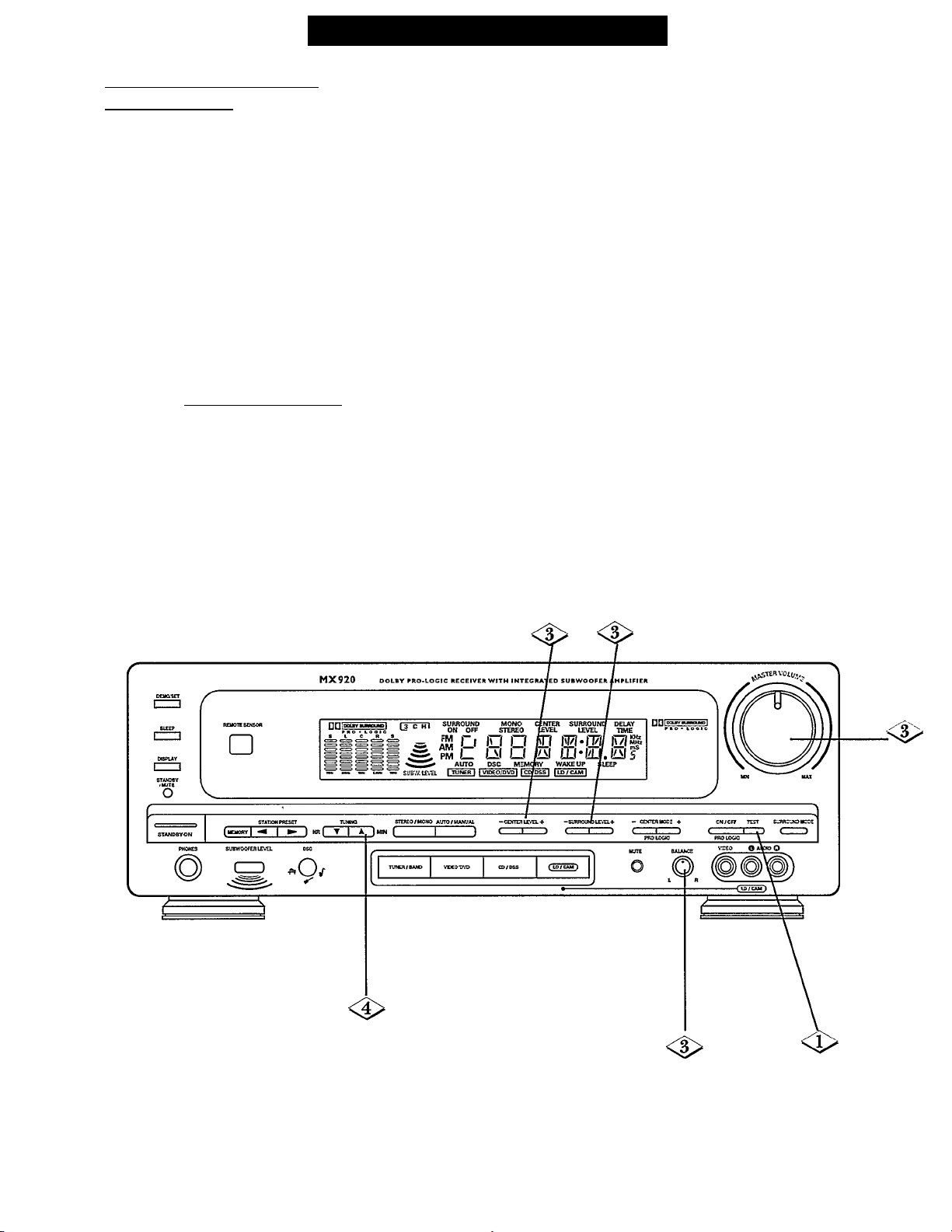
Surround Sound; (continued
To balance vour Speakers for
Surround Sound;
Use the TEST TONE function to set the correct
balance between the levels of the left, right, center,
and rear speakers in the Dolby ProLogic mode.
NOTES: Make sure your speaker Positioning is correct. For
details, see page 6. It is recommended to balance the Speakers at a
normal listening level
With the receiver on, press the TEST button on the
I front panel of your Receiver.
You will hear a test tone from the Front Left,
Center, Front Right and Left/Right Surround
Speakers, one by one, in a repeating cycle.
NOTE: You will not hear a test tone from the Subwoofer.
nn I DOI^Y SURROUWD
PRO • LOGIC
-Dolby’’, “Pro-Logic”, and the Double-D symbol are trademarks of Dolby Laboratories
Licensing Corporation.
Manufactured under license from Dolby Laboratories Licensing Corporation.
<P
Adjust the sound level of each Speaker until they
all sound equally loud.
- Use the MASTER VOLUME knob to adjust
the Front Left and Right Speaker volume level
to a normal listening level.
- Use the BALANCE knob to equalize the Front
Left and Right Speaker levels.
- Adjust the Center Speaker sound level with the
CENTER LEVEL (+) or (-) buttons.
- The Surround Speakers sound level can be
adjusted with the SURROUND LEVEL (+)
or (-) buttons.
NOTE: The Equalizer, which appears in the Receiver’s display,
will show the loudness of each channel (Front Left and Right,
Center, and Surround Left and Right) when in the TEST mode.
When you are satisfied with the levels from each
Speaker, press the TUNING UP
(A)
button to turn
the tone off.
22
Page 23
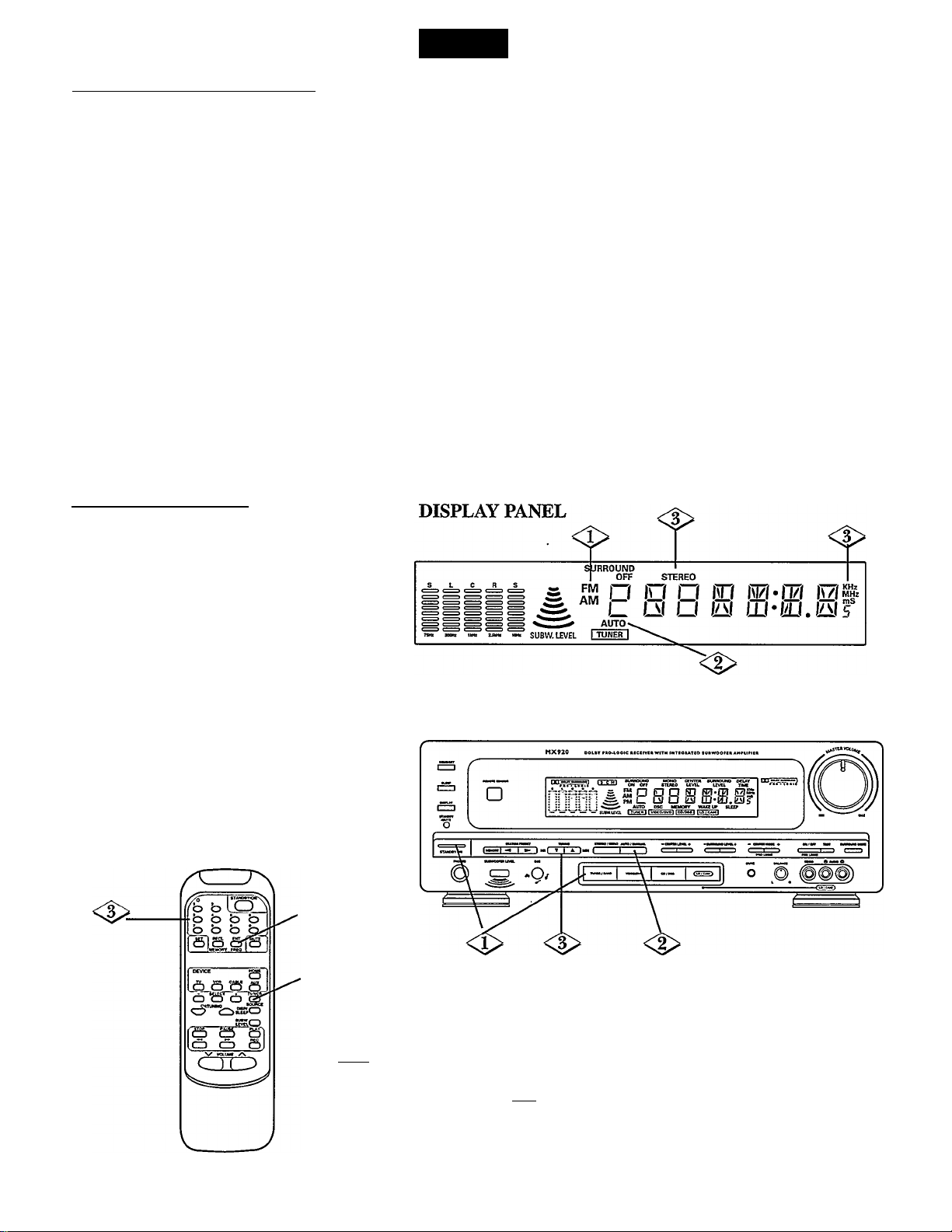
AUTOfmaticì/MANUAL I\inin^:
Tuner
4>
<l>
<l>
Turn the Receiver on. Select FM or AM. Press the TUNER/BAND button until the desired waveband (FM or AM) appears
in the display.
I
Press the AUTO/MANUAL button.
The display will show the last tuned frequency and “AUTO” will appear in the receiver’s display.
To find another station, press the TUNING UP
The Tuner will now search until a station of sufficient strength has been found.
NOTE; If the station found is not the desired one, simply press and release the AUTO/MANUAL button again. Weak stations are
skipped during automatic tuning. They can be tuned to manually.
Now, try MANUAL tuning. Press the AUTO/MANUAL button until “AUTO” disappears from the display. Then, press
and hold the TUNING UP
you quickly press and release the TUNING UP
intervals. Or, press the Remote’s CH/TUNING
.NOTES: When tuning, the sound will be muted to eliminate interfering background noises. When a station is found, the audio signal
will come back on.
"STEREO” will appear in the display when an FM-stereo signal is received.
With weak FM Stereo signals, you may hear static or background noise. These noises can be suppressed by switching to MONO. Simply press the
ST(ereo)/MONO button. “STEREO” will disappear in the display.
(A)
or DOWN
(A)
or DOWN
(T)
buttons until the desired radio station frequency or program is found. If
(A)
or DOWN
(A)
or
(T)
(T)
(T)
buttons.
button.
buttons, you can change the frequency at small
Direct Frequency Input;
NOTE; The Receiver’s remote control must be used
for this feature.
Press the SOURCE button until FM or AM
appears on the Receiver’s display. Also,
press the SOURCE button to select FM or
AM tuning.
^2^ Press the ENT(er) button. “
on the Receiver’s display for a few seconds.
Then, “FM-.-MHZ or AM- - KHZ” will
appear.
Using the NUMBER button, enter the
desired frequency (for instance, to receive a
station with a frequency of 98.5 MHz,
press the 9 button, then the 8 button, then
press the 5 button).
NOTE; If no button is pressedfor five seconds, or if
any button other than the NUMBER buttons is pressed,
the Receiver will return to the last station tuned.
-----------
” will appear
•<i>
DISPLAY PANEL
S L C R S
23
SURROUND
S PM
AM
AUTO
I TUNER I
<l>
OFF
Page 24
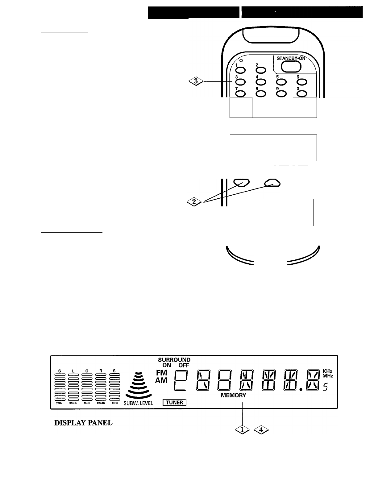
Preset Memory:
Your Home Theatre Receiver can store up to 16
FM stations and up to 8 AM stations.
While in the TUNER mode, press the
MEMORY button. “MEMORY” will flash
in the display.
Press the CH(annel)/TUNING buttons to
select the frequency (or station) you wish
to memorize.
<|>
<$> Press the MEMORY button again. Be sure
Using the Remote Control, select a memory
location number (1-16 for FM, 1-8 for AM)
with the NUMBER buttons.
-OR-
Using the Receiver’s front panel buttons,
press the STATION PRESET (◄) or (►)
buttons to select a memory location number.
NOTE: When using a two-digit memory location
number (such as 12), press both NUMBER buttons 1
and 2 within five seconds.
to press this button within five seconds
after entering the frequency. “MEMORY”
will appear in the display.
Recall Preset Station;
The stations memorized in the Home Theatre
Receiver can be quickly selected.
Press the Receiver’s STATION PRESET
(■^) or (►) buttons until the desired
frequency appears in the display.
“MEMORY” will also appear in the
display.
-OR-
Using the remote’s NUMBER buttons,
enter the desired memory location number.
Tuner (coN[riNUEb
DISP/ ^
sleep'
SUBW./
level'
----------
1 MUTE 1
HOME
o
AUX
o
o o o o
SOURCE
! i
o
REC
oj
RECL ENT
Q.
^ CD o
MEMORY FREQ
DEVICE
TV VCR CABLE
O o o
- SELECT + TV/VCR
CH/TUNING
/' STOP PAUSE PLAY^
CD
« ►►
f I
C—)
V VOLUME /\
(ZJTD
<
24
Page 25
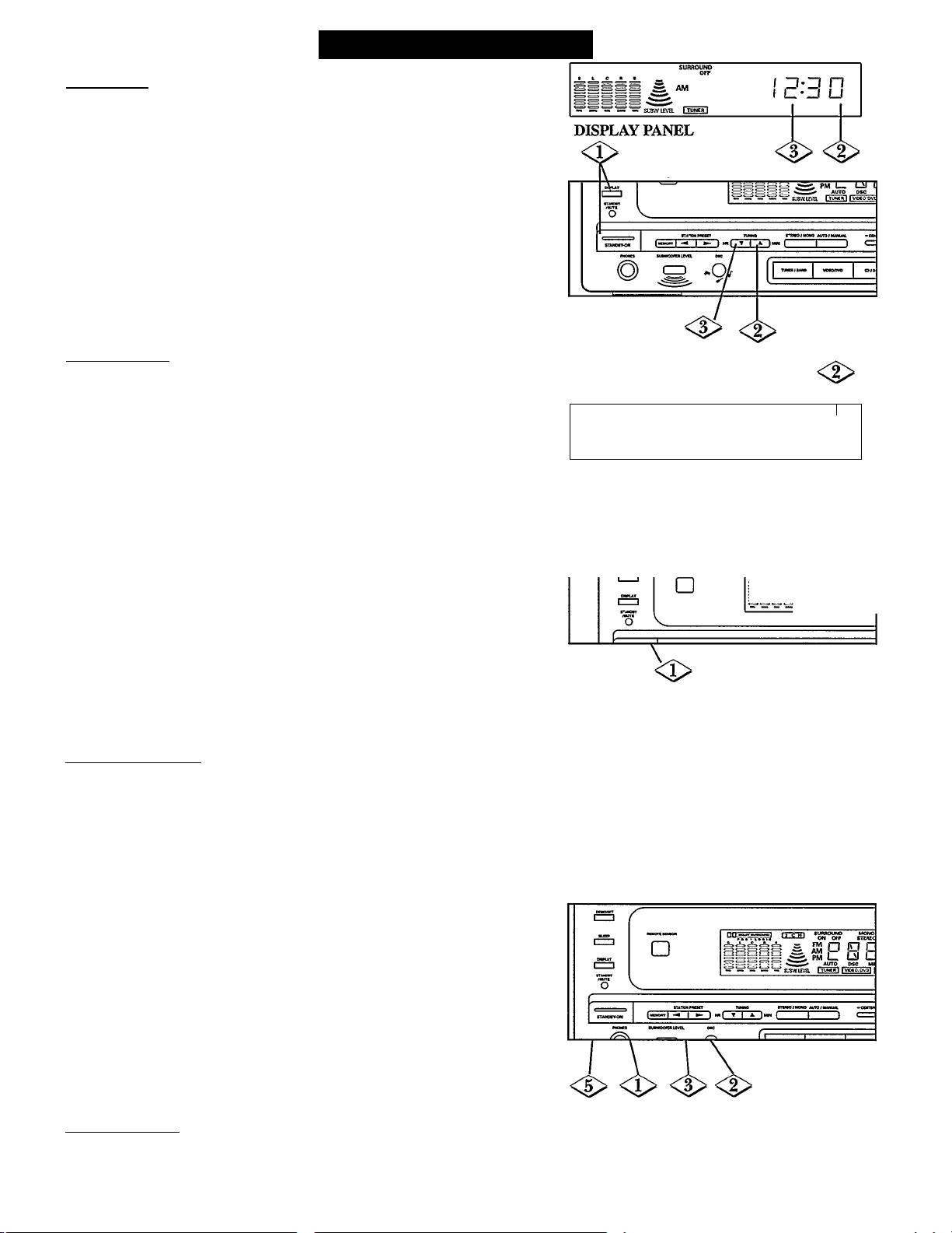
Additional Features
Clock Set:
Your Home Theatre Receiver will display a Clock when the unit is turned off.
Turn the Receiver on and press the DISPLAY button. The Clock will
appear in the display.
<|> Press the TUNING
<l>
Press the TUNING (T) “down” button until the correct hour appears.
After a few seconds the display will switch back to its previous
information. The Clock is now set.
NOTES; The Clock can be switched from a 12 hour mode to a 24 hour mode. To change
the Clock Hour mode, when in the Clock Adjust mode, press and hold the DEMO/SET
button until the desired Clock Hour mode appears.
You must press the buttons within a few seconds or the Clock Set mode will exit.
Sleep Timer;
Your Home Theatre Receiver can automatically turn itself off anywhere from
10 to 90 minutes away. You choose how long you want the Receiver to stay on,
and when the “Sleep” time arrives, the Receiver will turn off.
Using the buttons on the front of the Receiver:
<P
11101 the Receiver on. “SLEEP” will appear in the Receiver’s display.
<l> Press the SLEEP button repeatedly until the desired “time off” appears in
the display. The Sleep Timer is now set. “SLEEP” will stay on the display.
Using the remote control:
Tum the Receiver on and press the DISP/SLEEP button. “SLEEP” will
appear in the Receiver’s display.
T
<l> Now, press the SLEEP button repeatedly until the desired “time off” appears
in the display. The Sleep Timer is now set. “SLEEP” will stay on the display.
NOTE; During the last ten minutes of a Sleep Timer, the sound level will slowly “fade out”.
The “fade out” can be stopped by pressing any button.
To cancel the Sleep Timer
1. Press the SLEEP button repeatedly until “00” appears in the display.
2. The “SLEEP” will flash for few seconds then disappear.
(A)
“up” button until the correct minute appears.
-
DISPLAY PANEL
<S>
SURROWS
no
u-c u
<3>
MX920 ooL»T rftO'toQie a
tavtuvg. E
n
» AM M I
Wake Up Timer;
Your Home Theatre Receiver can automatically turn itself on. You choose
when you want the Receiver to turn on, and when the “on” time arrives, the
Receiver will turn on.
1\im the Receiver on and press the DISPLAY button three times. “WAKE
I UP” will flash in the display.
<I> Press the TUNING
Press the TUNING
Press the DEMO/SET button until “WAKE UP” appears in the display.
I The desired “time on” appears in the display. The Sleep Timer is now set.
1\im the Receiver off to set the Wake Up Timer.
NOTES; To turn the Wake Up Timer off, follow steps 1.
Press the DEMO/SET button, “WAKE VP” flashes and then disappears from the display.
The Receiver must be off for the Wake Up Timer to work.
The Receiver will come on in the last mode it was set in.
^^h^leceiver^ssoun^eve^il^low^ad^ii^vheiUh^ini^is^ome^iu^^^^^^^^
(A)
“up” button until the correct minute appears.
(T)
“down” button until the correct hour appears.
DISPLAY PANEL
<$>
DEMO Mode:
Press the DEMO/SET button to start a display demonstration program. Several features of your Receiver will now be shown
one after another in the display. To stop this function, simply press any button on the Receiver.
25
<$> <t>
I n-u □
I u- I u
<i>
Page 26
Remote Control r Direct Entry
Your remote control is set to work your Home Theatre Receiver and many infrared remote controlled TVs, VCRs, and Cable
Controllers. Many CD Players, or Laser Disc Players, or Audio Cassette Decks can be controlled as well. There is no guarantee
this remote will operate your brand of equipment or will operate all functions of your equipment.
NOTE: These instructions cover setting up your
remote to operate a TV. To setup the remote for
additional equipment, such as a VCR or
CD Player, follow these instructions. But, be sure to
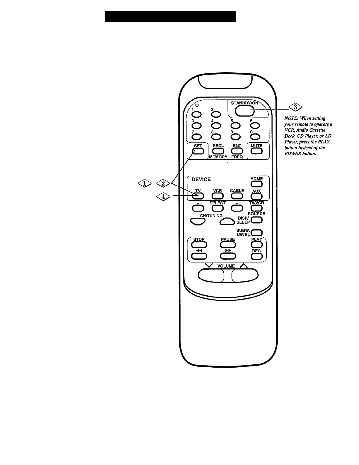
press the desired MODE SELECT button (VCR,
AVX, etc.).
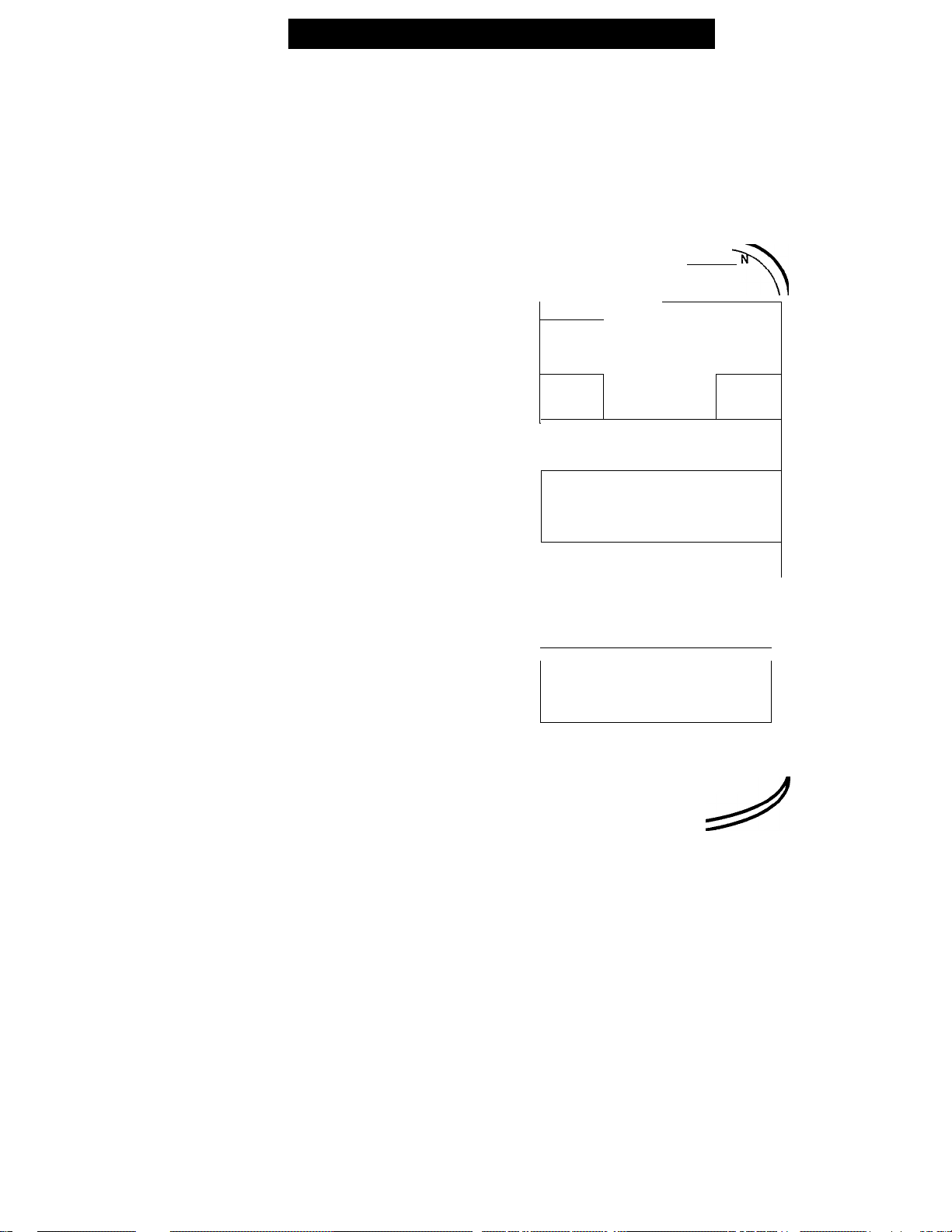
First, press the “TV” MODE SELECT
button. Now, press the STANDBY*ON
button.
- If the TV turns on, the remote may be
setup to operate your TV. Go ahead
and try other remote buttons.
- If the remote does not turn the TV
on, follow these steps:
<P
<t>
<$>
<$>
First, look up the three-digit brand
remote code number for your brand of
TV. The brand remote codes are listed
on pages 28-32.
NOTE: If more than one brand remote code
number is listed, you may have to try more
than the first three-digit code number in order
to locate your TV’s remote code.
Press and release both the SET button
and “TV” MODE SELECT button at
the same time. The LED on the remote
will light up.
Using the NUMBER buttons, input
the three-digit code number. The
LED will go out when a three-digit
code number is entered.
NOTE: If a three-digit code number is not
correctly entered, the LED will stay on. Press
the “TV” MODE SELECT button and start
again at step one.
Press the “TV” MODE SELECT
button again. Now, point the remote at
the TV and press the STANDBY*ON
button. If the TV turns on, try all the
remote’s TV function buttons. For
details, see page 16.
If the remote does not operate your
TV, repeat the above steps using the
next code number listed for your brand
of TV.
If after repeated attempts using all remote
code numbers listed for your brand TV,
t2UheJ|SearcITjnediodon£age_2^
<s>-
<!>'
“TV” MODE
SELECT
BUTTON
/
A
STANDBY«0
o o
- ^
lb
SET RECLoENT
1/ J
/
DEVICE
MEMORY FREQ
TV VCR
o O o
b b
,o
o
CABLE
[(ZD O o
/ - SELECT
o o o o
CH/rUNING
/' STOP PAUSE PLAYV
( ) ( ^
«
^
C—i
N/ VOLUME /\
+ TV/VCR
SUBW./—^
I PVPI ^ -1
►►
CD
I
b 1
MUTE
o
s
________
HOME
o
AUX
o
SOURCE
o
REC
oj
26
Page 27
Remote Control - Search
Your Home Theatre Receiver’s remote can be set to work your TV (and VCR, Cable Controller, CD Player, etc.) by what is
called the Search method.
If the Direct Entry method, described on the previous page, did not set your remote to operate your equipment, then follow
the easy steps listed below.
NOTE; These instructions cover setting up your
remote to operate a TV. To set up the remote for
additional equipment, such as a VCR or CD Player,
follow these instructions. But, be sure to press the
desired MODE SELECT button (VCR, AUX, etc.).
Press and release both the ‘TV” MODE
SELECT button and the SET button at
the same time. The LED on the remote
will light up.
Press and release the SET button again.
r
<l>
<a>
The LED will begin flashing.
Press and release the STANDBY*ON
button until the TV comes on.
To find the correct code, you may have
to press the POWER button many
times. Each time you press the
STANDBY'ON button, another code is
being tried.
NOTE; If you accidentally pass the correct code,
press the SET button. Again, press and release
the STANDBY»ON button until the TV comes
on.
When the TV comes on, press the ‘TV”
MODE SELECT BUTTON.
Now, make sure the remote works your
TV correctly. Press the STANDBY*ON
button and all other related function
buttons. For details, see page 16.
If after repeated attempts, the steps listed
above do not work as listed, the remote will
not operate your TV.
NOTES; Use the above method for setting your
remote to operate your Cable Controller.
When using the Search method to set your VCR or
Audio Cassette Deck, first put a tape in and leave the
power on. Instead of pressing the STANDBY»ON
button, press the remote’s PLAY button. When trying
to set your CD Player or Laser Disc Player, first put a
disc in and leave the power on. Instead of pressing
the STANDBY*ON button, press the remote’s PLAY
button.
27
Page 28
Additional Remote Control Functions
As stated before, this remote control will operate many infrared remote controlled TVs, VCRs, Cable Controllers, CD Players,
Laser Disc Players and Audio Cassette Decks. The following lists describe which remote control buttons most commonly operate
the various equipment. There is no guarantee this remote will operate your brand of equipment or will operate all functions of
your equipment.
ТВОЕ FUNCTION OF THE FOLLOWING BUTTONS ARE FOR YOUR REFERENCE, FOR MORE DETAIL, PLEASE
REFER THE INSTRUCTION MANUAL OF YOUR EQUIPMENT,
<TV><HOME>
• [STANDBY*ON] To turn the TV on or off.
• [0-9]
Direct channel selection.
• [ENT] Press to finish channel selection when
using number buttons.
• [CH]
Channel up and channel down.
• [RECL] Recall last channel.
• [VOLUME Volume up and down.
• [MUTE]
• [TVA'CR]
Audio mute.
Switch from TV to AA^ input or from
AW input to TV.
• [DISP]
• [SELECT]
• [+]/[-]
• [SUBW. LEVEL]
Thm on or off on screen display.
Select on screen adjustment.
Press to adjust on screen adjustment.
To adjust subwoofer level up and down.
• [PLAY] Start playing VCR.
• [PAUSE] Pause VCR.
• [STOP] Stop VCR.
• [F.F]
Fast forward VCR.
• [REW] Rewind VCR.
• [REC] Record VCR.
STANDBY«0?P4\
О о
О О О О
7__ 8
_______ 9_______ О_______
О О О О
RECL ЕНГ
О О
MEMORY FREQ
DEVICE
TV VCR CABLE AUX
О О О О
о
CD s
_________
STOP PAUSE PLÄY\
CD СЗ О
\/ VOLUME /\
SUBW.i«—ч
tgygii J
MITTE
О
CD
REC
<CABLE>
• [STANDBY*ON]
• [0-9]
• [ENT] Press to finish channel selection when
• [CH]
• [RECL] Recall last channel.
• [SELECT]
• [+]/[-]
• [SUBW. LEVEL] To adjust subwoofer level up and down.
• [PLAY] Start playing VCR.
• [PAUSE] Pause VCR.
• [STOP]
• [F.F]
• [REW] Rewind VCR.
• [REC]
о о
Ь Ь Ь Ь
Ь Ь Ь Ь
SETОRECL ЕМТ Г MUTE
ООО
MEMORY FREQ I
_______________
DEVICE НОЦЕ
TV VCR CABLE AUX
О О О О
- SELECT ♦ TVA'CR
О О О О
STOP PAUSE PLAY\
СО СО О
CD СО Oj
N/ VOLUME /\
To turn the convertor on or off.
Direct channel selection.
using number buttons.
Channel up and channel down.
Select on screen adjustment.
Press to adjust on screen adjustment.
Stop VCR.
Fast forward VCR.
Record VCR.
28
Page 29
Additional Remote Control Functions
<VCR>
• [STANDBY*ON]
• [0-9]
• [CH]
• [TVATCR]
• [SUBW. LEVEL] To adjust subwoofer level up and down.
• [PLAY] Start playing.
• [PAUSE] Pause.
• [STOP]
• [F.F]
• [REW] Rewind.
• [REC]
To turn the VCR on or off.
Direct channel selection.
Channel up and channel down.
Switch from cable to AfV input or from
AA^ input to cable.
Stop.
Fast forward.
Record.
A
/^T STANDBY»dftrx\
H 1
b b b
b b b
SETORECL
O
MEMORY
DE V I C E
o O O
c
/
STOP
CD
PAUSE
CD
la a
\/ VOLUME /\
b
EWT
MUTE
O
o
FREQ
HOME
O
o
- SELECT *■ T}W£R
o o o o
^ s l e e p U - ;
SUBW./—\
LEVELL J
oJ
COED
o o
o o o o
o o o o
RECL EKT
o o
(5
MEMORY FREQ
VCR CABLE AUX
0
____
SELECT _±_ TVATCR
O O O CD
^^STOP^ PAUSE PLAY \
[CZD
\/ VOLUME /V
dED
CD
OOP
O
oj
<AUX>
• [STANDBY*ON] To turn the equipment on or off.
• [0-9]
• [TUNING]
• [SUBW. LEVEL]
• [PLAY]
• [PAUSE]
• [STOP] Stop.
• [F.F]
• [REW] Rewind.
• [REC] Record.
[VOLUME
• [MUTE] Audio mute.
number entry.
Tuning up and down.
To adjust subwoofer level up and down.
Start playing.
Pause.
Fast forward.
Volume up and down.
29
Page 30
Remote Braird Codes
ABC
Admiral
Aiwa
Akal
Amark
Amstrad
Anam
Anvis'ion
Acx;
APO
Archer
ASA
ASIA Giant
Audio Dynamics
AWA 062,073,178,181
BEST
Bell & Howell 153
Braksonic 066
Cablestar
Canon
Candle/Cit'izen 031.032,042.049.053.055
Carver
Centurion
Chun Yun 029,071,073,099
Chung Hsin 099,117,118,139,171
Cokxtyme 031,039,042
Concerto
Contec/Cony 064,090,125,135,
Coronado
Craig 064,090 013.014.047,102.103
Crown 140
Curtis Mathes 013,017,031,033
CXC 064
Daewoo 031,034,042,055,076
Daytron 013,031,033,042
DBX
Denon unified 253
Diamond 042,119
Drake
Dual
Dynatech
Eagle
Eastern
Electrohome 031,042,047,048,055
Emerson
111,115.153
042,119,131,133
078,140,145
045
064,094,120
029,031,034,042,055,071
117,118,139,156
160,164,204
088,090,145,161,169
13,33,42
117,139,156
031,032,042,169
136,137,142,143
145,146,173
140,145
042,111,113,115
126,145,153,161,211
118,145,215,216
055,145
089,118.119,120,124
145,169
020,031,036,037,038
042,045,055,063,064
065,066,067,089,090
092,135,140,145,146
159,162,163,164,174
182,198.206,207,208
209
256,239
228
071,147
034,035,039,056,061
065,066,092,113
070
032
010,056,058,099
064,069
049,050,051,144
005,028,032,033.047,111
080,091,096.107,108,143
007,047.049.050.051
071,074,092,131,132
144
005,028,048,062,080
096,118,119,134,137
143
062,137
010,056,058,099
056
070,071.129,131
028,032,055,088
004,014,017,021,022
023,024,025,026,028
030,033,038,045,046
051,053,055,064,065
066,067,068,069,070
071,078,100,110,111
116,125,136,141,142
145
034,046,053,069,072
002,117,118
125
094
123,133
062
002,117,118
013,014,015,016,017
064
117,118
134,129.132,130
044
107,109
023
024.046
111.112
30
Page 31
Remote Brand Codes ccont)
Fisher
Fullness
Funai
GE
Gemini
General (Fujitsu) 051
Gl/Jerrold 030,032.069.070.071
GMI 080
Goldstar
Graetz
Haltal
Hallmark 031,042
Hamlin
Harman Kardon 236 010
Hitachi
HWALIN
lEEC
Infinity 178
Inkel
Instant Replay
ITT
Jasco
JBL 178
JCL
JC Penney 013,031,034,042,046
Jean
JEBSEE
Jensen
JVC 1
014.023.024,044.095
096
220.223
058.064.070.090.163.164
220.223
031,042,046,047,048
082,083,090,094.111
113,114.115,120,148
180,212,213,221
013,031,032,034,042
055,075,079,080,088
118,140,145,146,169
003,028,031,032,042
043,044,048,049,055
071,122,039,140,142
143,145.146,155,169,173
047,048,088,111,113
114,115,118,134,143
145,180,212
071,139,191,223
031,040,042 056,079
011,017.022.059,060
083,142,143,145,146
154,175,176,202
228
257,240
231
241
234
013,014,016,018,019
026.027,036,060
070,071,072
002,047,049.050,051
074,075,077.102.144
003
010,032,033.107,108
111,132
056
020,056,070,071,106
107
049,051,123
056
049,050,051
010,011,020,026,028
032,047,049,050,051
057,099.107.123.135
144
011,026,028,033,042
043.056,057,058.079
083.099,107.138
037,038,087,090,111
072,073.074.075.081
082,083,085,086,087
090,091,092,099,101
102,103
029,041,042,050,051
052
009,069,104
126
138,136,137
094
021
018,048
021
004
065
036,037
038
025
035
Kale Vision
Karcher
Kawasho
Kenwood 031,042,169
Kloss Novabeam
KMC
KOKA
Kolin
KTV
Lenco
031,042,133,137
149,150
055,140,145
099.117.118.138,139
171 ’
042,055,064,140,145
205
227,243
026,043.056,057,058
099
31
038
024,120
057
005.011
057,058
059,060
080,081
082,083
084,085
071
026,027
079
086,087
088,089
090
Page 32
Remote Brand Codes (CONt)
Lodgenet 153
Logik 153
Luxman 031,032,042,169 242 013
LXI
Wacom 007,008,009,053,055
Magnavox 013,031,033,042,045
Majestic 153
Marantz 031,042,087,118,119
Marta
Megatron
WEI 049,050,051
Memorex 153 241
MGA/Mitsubishi
Midland
Minolta 020,107
Mission
Montgomery Ward
MTC 031,032,034,042,118
MultiTech
Multivision 054
NAD 021,025
NEC 010,013,031,032,033,120
Newave 032
Nordmende
NSC 038,113
OAK
Onkyo 233
Optimus 249
Panasonic
(National)
Paragon(Zenith)
Pentax 020,092,107
Philco
Philips 016,031,034,049,050
Pioneer 018,031,035,042,156
Portland 042,055,118,140,145
Proton 029,031,042,055,057
Pulsar 004
Quartz 026
Quasar
011,013,015,021,023
024,025,178,198,200,201
049,050,102,118,126
140,145,149,150,151
178,179,180,184,186
149,150,173,178
078
013,031,033,034,042
047,048,055,089,096
101,118,119,124,140
163,164,169
140,153 131
161,169
034,041,042,053,118,169
120,169,222
016,082,083,094,097
098,120,177,178,187
188,189,190,191,192
193,194,212,218
031,034,042,049,102
118,120,126,140,145
146,149,150,151,178
179,184,186,217
103,120,126,140,145
146,149,150,178,179
184,186,217
170,203
071,0/2,073,075,077,167
078,081,086,139,145,146
224,219
082,083,094,120,213 235
251 006,016,026,028,049
244.245
247.246
252,235 010,049,050,051,107
250
248,232 015,020,037,043
112
018,019,026,033,107
066
000,001,043,044,045
050,051,059,062,092
117,144
010,026,049,050,051
052,057,092,099,108,117
012,032,033,111
014,032,033,049
051,070,071,072
028,036,032,055,063,081
082,083,084,086,088
107,114,115,116
002
047,070,071,102,103
002,047,070,071,112
007.010.011.018.026.131
033.043.052.056.057.132
058,079,092,099,105,145
056 057
120,121,122,123,124
144
006,016,028,049,050
051,059,062,092,117
144
006,028,049,051,059
117,123
099,107,133
005,062,096,137,143
049,050,051,144
068,078,095,096,097
100,109,117,118
006,047,053,055,076
029,031,032,035,
014
056
000,001,044,045,063
078,095,096,097,100
109,117,118
002,036,115,116
100
045
100
014,097
002,003
067,068
072,075
091,092
006,104 047,103 043
100 101
006,019
020,028
093
100
006
095
073,074
076,077
102
095 029,030
031
32
Page 33
Remote Brand Godes (CON'T)
Radio Shack 002,013,024,064,090
Radiolone 057
Randek 117,118
RCA 000,011,031,034,042
Realistic 002,013,024,063,064
Regal
Regency
Rembrandt 038
SABA
SAE 100
Salshg 146
Salora
Sampo 013,029,031,033,042
Samsung 013,031,032,033,034
Sansul 043,056.099 007,094 098,099
Sanyo 007,008,009,011,013
Schaub Lorenz 056
Scientllic Atlanta
Scott
Sears/LXI 011,013,014,015,021
Sharp 001,002,006,031,042,225
Sherwood 065,066
Shintom
Shure
Signature 069
Singer
Skygiant
Sony 071,078,091,116,121
Soundesign 030,031,042,049 257,255
Sowa 012,027,071,117.139.171
Sprucer
SSS 034,064
Standard Component 038
Starcom
Stargate
STS
Supertech 241
Sylvania 013,031.033,042,046
113,142,145,146
A-B Sw,241
111,112,113,114,115
120,134,204,221,226
067,142,145
183
071,072,074,108,138
141,147,155,171,197
042,055,069,118,136
140,142,145,146,161
169,210,211,223
014,019,023,024,028
062,073,084,095,096
104,138,139,165
013,033,038,042,090
145,146,163,164
023,024,025,031,042
044,069,084,085,095
096,113,140,143,145
154,161,163,169
055,123,125,127,140,201
145,146,198,199,200,206
223
128,129,130,131,132
133.139,171,172
049,050,102,118,126
235 013,018,026.032,049
240,231 018,020,032,047,049,123
240 013,014,018,026,032
240
237 005,040,058,089,111
247
238,239 091,092,093,094,136
070,071.089,102,129
131
051,054,073,074,075,140
077.085.087,102.107,148
033,049,050.051,070
071,072,089,102,103
111,129,130,131,144
056
082
129
002,028,047,053,091
026,027,104
000,008,009.013,014
026,027,104
004,028,030,066,082
083,084,086,100,111
136,142,146
013,014,018,019,020
026,032,033,036,095
107,111
128,129,130,131
092,112
006,016,028.049,050
051,062,071,082,083
070
032,139(DSS) 048 049
112 091
029,042,050,052,103
077,078
105
002,004,038,116
008,016 022
029,030,033,034,040
048,071,085,088
108
070,078
124,128,131
032,035
030,032,069,070,075
089,091,101,102,103
004,042
020
105,107
050,052
053,054
100
051
111,112
113
055,056
33
Page 34
Remote Bran» Codes (con'T)
TADA
Tandy
Tashiko
Tatung
Teao
Technics
Techwood
Teco
Teknika
Telecaptlon II 022,164.214
Telefunken
Telerent 140,145,153
Тега 029,031.071,072,077
Texscan
Thomson/ProScan
Thom
TMK 031,032,042,169
Tocom
Toshiba
Totevision
Trans PX
Tri-vision
Tuntex 223
Uniden Satellite
Unika
Unitech
United Cable
United Satellite
Universal 046,048
Vector Research
Victor
Video Concepts
Videosonic
Video Way
Vidtech
Viewstar
Wards
Waner Amex
Westing House
Winer
Wise
Yamaha
012,015,025,026.027
061.071.073.093.117.171
118.012.138.139.168.172
083 252,235 051
031.032.042
068.105.106.107,109.195
110.139,155,157,158.000
222
031.032,034,042,049
050,053,055,064,118
119,140,143,144,145
146,151,153.161,163
164,169,178,179
139
111,113 056,074
005,011.014,015,021
024,025.056,069,073
093,100,118,138,143
161,172,199,214
145
052,154,196
034,042,118
002,004.013,031,033
034,037,038,042,042
046,048,049,050,113
118,126,140,145,149
150,163,164,178,184
049
034,042.118,169 230,254
229,237
026,071
032,033
001,056,057,058,059
079
056,057,058,070.071
072
003,029.032,033,049
050,051,070,071
056
056
024
001,013,018.019,020 007,008,011,012 009,010 096
028,031,041.056,082
083,091,095.107,109
136,142
032,033.047,102,103
111
047,102,103
010,011,082,084,099
059,099,126.127
011,092,099
047,102,103
028,032,033,040,047
049,051,058.070,071
076,089,090,102,103
107,111,112.129,130
010,026,056,057,058
079,099
063
012.063
064,069
012,042
105
010
003,112
061,105,107,114
044,045,049,079,108
098,135
001,081,082.084,110
067
044,093,096.097
070,102
088
018.019
039
058,059
005
000.001,044,045,068
078,095,096,097,100
109,117,118
002
028
025.026
000.001 032,034
106
040,041
110
Yorx
Zenith 151,152
ШМ 223
013,033,042
015,044,091.092,096
34
007,008,013.015.016
127,122
121
017
Page 35

Tips if Something Isn’t Working
Please make these simple checks before calling for service. These tips can save you time and money since charges for installation
and adjustment of customer controls are not covered under your warranty.
NO POWER
Make sure the power cord is inserted fiilly into a 120V/60Hz outlet.
Check to be sure outlet is not on a wall switch.
Unplug the power cord, wait 1 minute, then reinsert the plug and push the POWER button.
NO VOLUME
REMOTE CONTROL
DOESN’T WORK
CAN’T TUNE
RADIO STATIONS
NO VOLUME
FROM SUBWOOFER
NOTE; Electrostatic discharge can cause unexpected problems. For example, causing the unit to fail to react to operator of the buttons. In that event, you should
reset the unit by disconnecting it from the household wall outlet.
Check the VOLUME knob on the unit.
Make sure the correct feature has been selected (for instance, “CD” shoidd be selected when playing a CD).
Make sure the speakers are properly connected.
“El” or “E2” is displayed on the front of the Receiver. Turn Receiver off and then back on. Make sure
speaker wires are not shorted together.
If headphones are plugged in, disconnect them.
Check, and if necessary, replace batteries.
Make sure the remote is pointed head-first at the Receiver.
Make sure the Receiver is plugged into an operating wall outlet.
The remote may be either too far away from the Receiver or not in front of the Receiver.
Make sure the correct MODE SELECT button was pushed.
Repeat channel selection.
Make sure the antennas are properly connected.
Make sure the Subwoofer speakers are properly connected.
At lower volume levels, the bass sound may not be as clearly heard. This is normal.
WARNING: IF YOU ARE UNABLE TO REMEDY A PROBLEM BY FOLLOWING THESE HINTS, CONSULT YOUR
DEALER OR AN AUTHORIZED PHILIPS SERVICE CENTER. UNDER NO CIRCUMSTANCES SHOULD
YOU TRY TO REPAIR THE SYSTEM YOURSELF, AS THIS WILL INVALIDATE YOUR WARRANTY.
35
Page 36

Glossary
A/V Inputs:
Allow injection of AfV signals, isolated from one another, to TV
receivers, VCRs, camcorders, and combis through discreet channels by
passing through the mner and other RF circuitry.
Balance:
Adjusts the relative volume levels of left and rights channels for optimal
stereo effect. Compensates for channel imbalance and non-symmetrical
loudspeaker positioning.
Bass:
The lower range of audio frequencies, up to approximately 500Hz.
Decibel (dB):
The minimum change in sound intensity that a human ear can distinguish.
A doubling of volume is a lOdB increase. To double volume in a stereo
system, a 10-fold increase in power output (WATTS) is required.
Dolby Pro-Logic® Surround Sound:
A movie or other source with audio encoded in Dolby Pro-Logic® creates
a very realistic soundfield-much like you would experience if you were
actually in the movie yourself. There are four components to this
soundfield: Front Left Channel (one speaker). Front Center Channel (one
speaker). Front Right Channel (one speaker), and Rear Channel (two
speakers placed to the left and right rear). The front center channel
contains mostly dialogue and center sound effects. The dialogue and
sound effects are therefor reproduced exactly where they should be-the
very center of the soundfield above or below the television, or through the
center speaker via a center channel output from the receiver. The front left
and rights speakers contain directional sounds (like a car going from left
to right across the screen) as well as other important effects that help
“steer” the audio more realistically to the listener’s ears. The rear speakers
help to re-create the reflective ambience of the original room in which the
audio was recorded. They generate short echos and delays that help make
the entire audio experience more lifelike.
Dolby® 3-Chauuel:
Dolby® 3-Channel operates like Dolby Pro-Logic© except in the Dolby®
3-Channel rear speakers are not used. Dolby® 3-Channel is usually
included on Dolby Pro-Logic® receivers for users who wish to wait to
buy rear speakers or for those whose home theatre environment is too
small to accommodate rear speakers.
Graphic Equalizer:
Tone control device that cuts or boosts different frequencies within the
audio band. A graphic equalizer provides greater control over tone than a
single-knob tone control.
Hertz (Hz):
The basic unit of measure of frequency. One hertz equals one cycle
per second.
L/R Audio:
This abbreviation stands for Left and Right Audio.
Ohm:
A unit of electrical resistance or impedance calculated by dividing the
voltage applied to a circuit by the current (amperes) flowing in it. The
higher the number, the higher the resistance or impedance.
Signal-to-Noise Ratio:
The ratio, measured in decibels, between the ma.xlmum signal level and
the noise level with no signal present. The higher the value, the better the
sound reproduction.
Surround Output Level:
One select Dolby Pro-Logic® A/V receivers, this feature allow s you to
adjust the rear speaker level relative to the front speaker level according to
your viewing location and individual preference.
Surround Sound:
A system of audio reproduction that uses four or more speakers to
simulate the full three-dimensional effect of a live musical performance or
cinematic environment. (See also Dolby Pro-Logic® Surround Sound.)
Test Tone:
Dolby Pro-Logic® Surround Sound receivers offer this feature to allow
individual adjustment of all four channels (Left, Center, Right, and Rear)
according to your viewing location and individual preference. To set the
balance, a test tone is sent to each chaimel in a repeating cycle.
Total Harmonic Distortion (THD):
A measure of the distortion produced in an audio system as a result of the
production, within the system, of harmonics or multiples of the original
audio signal.
Frequency:
In musical terminology, frequency generally refers to the pitch of a sound.
The frequency of a sound is measured in cycles per second (hertz). One
cycle is one complete audio waveform. Bass frequencies have a lower
number of waveforms (or cycles) per second, and treble frequencies have
a very high number of waveforms (or cycles) per second.
Frequency Response:
The frequency range in which an electronic component can accurately
reproduce its input. Humans can hear from 20Hz to 20,000Hz (20KHz).
An ideal component would have a Frequency Response, totally flat or
without any deviation, from 20Hz to 20KHz. Frequency Response
specifications are measured in db based on how closely a component’s
response resembles that of the ideal.
limer:
A radio receiver without amplification.
Wow and Flutter:
Audible periodic variations in the pitch of a sound from the audio system.
The low-frequency variations (up to about lOHz) are wow, while the
higher-frequency variations are flutter.
36
Page 37

Specifications*
RECEIVER;
Output Power...................................................................................
Surround Modes:
Front...................................................................................................................................................................................................45 W
Rear....................................................................................................................................................................................................45 W
Center.................................................................................................................................................................................................45 W
Music Power (IKHz,)............................................................................................................................................................................... 2xl00W
Total Harmonic Distortion
Intermodulation Distortion........................................................................................................................................................................<+10%
Power Bandwidth................................................................................................................................................80 - 16,000 Hz (at 10% THD)
Frequency Response....................................................................................................................................................... 40 - 20,000 Hz, +- 2dB
Surround Level........................................................................................................................................-lOdB ~ +10dB to main output level
Center Level............................................................................................................................................-lOdB ~ +10dB to main output level
Subwoofer Level........................................................................................................................................................................- 6 dB ~ + 15 dB
Supply Voltage................................................................................................................................................................................... 120V/60Hz
Tuning Range:
FM.....................................................................................................................................................................................87.5 - 108MHz
AM....................................................................................................................................................................................520 - niOKHz
...................................................................................................................................................1% at 1 KHz, 4ohm
SPEAKERS;
Front L/R(4Q)
....
5"
.2%"
,30W
.50W Max. power
Center (4£2)
Woofer
....................
Tweeter
Avg. power
...................
2 X 45W (4ohm) per channel at 80Hz - 16kHz (10% THD at IKHz).
Surround L/R (8£2)
.............
............
...............
...............
...........
...........
30W
50W
5"
2"
Full-range
Avg.power
Max. power
....................
..................
.................
.......
3‘/2"
....22.5W
.......25W
POWERED SUBWOOFER SPEAKER;
Output Power .........................................................................................................................................................................
Total Harmonic Distortion....................................................................................................................................................1% at 70Hz, 4 Ohm
Frequency Response...........................................................................................................................................................................45 ~ 107Hz
Woofer..............................................................................................................................................................................................................6'/2"
^Specifications subject to change without notice.
45W @ 10% THD
37
Page 38

LIiMITED WA(^RANTY
AUDIO SYSTEM
One Year Free Labor
One Year Free Service on Parts
This product must be carried in for repair.
WHO IS COVERED?
You must have proof of purchase to receive warranty service. A sales
receipt or other document shotving that you purchased the product
is considered proof of purchase.
WHAT IS COVERED?
Warranty coverage begins the day you buy your product. For one
year thereafter, all parts will be repaired or replaced, and labor is free.
After one year from the day ofpurchase, you pay for the replacement
or repair of all parts, and for aU labor charges.
All parts, including repaired and replaced parts, are covered only for
the original warranty period. When the warranty on the product
expires, the warranty on all replaced and repaired parts also e.xpires.
WHAT IS EXCLUDED?
Your warranty does not cover:
• labor charges for installation or setup of the product, adjustment
of customer controls on the product, and installation or repair of
antenna systems outside of the product.
• product repair and/or part replacement because of misuse,
accident, unauthorized repair or other cause not within the
control of Philips Consumer Electronics Company.
• reception problems caused by signal conditions or cable or
antenna systems outside the unit.
• a product that requires modification or adaptation to enable it to
operate in any country other than the country for which it was
designed, manufactured, approved and/or authorized, or repair
of products damaged by these modifications.
• incidental or consequential damages resulting from the product.
(Some states do not allow the exclusion of incidental or
consequential damages, so the above exclusion may not apply to
you. This includes, but is not limited to, prerecorded material,
whether copyrighted or not copyrighted.)
WHERE IS SERVICE AVAILABLE?
Warranty service is available in all countries where the product is
officially distributed by Philips Consumer Electronics Company. In
countries where Philips Consumer Electronics Company does not
distribute the product, the local Philips service organization will
attempt to provide service (although there may be a delay if the
appropriate spare parts and technical manual(s) are not readily
available).
MAKE SURE YOU KEEP..
Please keep your sales receipt or other document showing proof of
purchase. Attach it to this owner’s manual and keep both nearby.
Also keep the original box and packing material in case you need to
return your product.
BEFORE FIEQUESTING SERVICE...
Please check your ow’ner’s manual before requesting service.
Adjustments of the controls discussed there may save you a service
call.
TO GET WARPWsITY SERVICE IN U.S.A.,
PUERTO RICO OR U.S. VIRGIN ISLANDS...
Take the product to a Philips Factor^’ Service Center (see enclosed
hst) or authorized service center for repair. WTien the product has
been repaired, you must pick up the unit at the center. Centers may
keep defective parts.
(In U.S.A., Puerto Rico and U.S. Yirgin Islands, all implied
warranties, including implied w'arranties of merchantabilitv’ and
fitness for a particular purpose, are limited in duration to the duration
of this express warranty. But, because some states do not allow
limitations on how long an implied w'arranty may last, this limitation
may not apply to you.)
TO GET WARRANTY SERVICE IN CANADA...
Take the product to a Philips Consumer Service Center (listed
below), self-servicing dealer or authorized service depot.
Phihps Electronics Ltd.
601 Milner Avenue, Scarborough, Ontario, MIB IMS
(416) 292-5161
4977 Lev)' Street, St. Laurent, Quebec, H4R 2N9
(514) 956-0120
3695 Grandview Highway, Vancouver, B.C., V5M 2G7
(604) 435-4411
(In Canada, this warranty is given in lieu of all other warranties. No
otlier warranties are expressed or implied, including any implied
warranties of merchantability or fitness for a particular purpose.
Phihps is not hable under any circumstances for any direct, indirect,
special, incidental or consequential damages, howsoever incurred,
even if notified of the possibUity of such damages.)
MAC4848
Tins warranty yyives you specific legal rights. You may have other rights which vary from state to state.
Philips Service Company
REMEMBER...
Please record the model and serial numbers found on the product
below. Also, please fiU out and maU your warranty registration card
prompdy. It vvUl be easier for us to notify you if necessary.
MODEL #_________________________________________________
SERIAL# _________________________________________________
401 East Andrew Johnson Highway
(423) 475-8869
Jefferson City, Tennessee 37760
IB75S0E001
Page 39

Page 40

MX920AHT
IB7796E001
Philips Consumer Electronics Company
A Division of Philips Electronics North America Corporation, Knoxville,Tennesse 37914-1810, USA
Printed In Malaysia
T1J9672/17-1
YOMOl 27-001
 Loading...