

Philips MX5900SA User Manual

DVD VIDEO DIGITAL SURROUND SYSTEM
Need help? Call us!
Philips representatives are ready to help you with
any questions about your new product. We can guide you
through Connections, First-time Setup, or any of the Features.
We want you to start enjoying your new product right away!
CALL US BEFORE YOU CONSIDER
RETURNING THE PRODUCT!
1-800-531-0039
or
Visit us on the web at www.philips.com
MX
5900SA
MX
5900SA
O
P
M
Return
I
your Warranty
Registration Card
within 10 days
S
E
E
W
T
A
R
N
T
!
E
D
I
S
N
H
I
Y
1

Return your Warranty Registration card today to
ensure you receive all the benefits you’re entitled to.
• Once your Philips purchase is registered,
you’re eligible to receive all the privileges
of owning a Philips product.
Warranty
Verification
Registering your product
within 10 days confirms
your right to maximum
protection under the
terms and conditions of
your Philips warranty.
Owner
Confirmation
Your completed Warranty
Registration Card serves
as verification of ownership in the event of product theft or loss.
Know these
ssaaffeettyy symbols
CAUTION
RISK OF ELECTRIC SHOCK
DO NOT OPEN
CAUTION: TO REDUCE THE RISK OF ELECTRIC SHOCK, DO NOT
REMOVE COVER (OR BACK). NO USER-SERVICEABLE PARTS
INSIDE. REFER SERVICING TO QUALIFIED SERVICE PERSONNEL.
• So complete and return the Warranty
Registration Card enclosed with your
purchase at once, and take advantage
of these important benefits.
Model
Registration
Returning your Warranty
Registration Card right
away guarantees you’ll
receive all the information
and special offers which
you qualify for as the
owner of your model.
For Customer Use
Enter below the Serial No. which is located on the rear of the cabinet. Retain this
information for future reference.
Model No. _______________________
Serial No. ________________________
This “bolt of lightning” indicates uninsulated material
t
an electrical shock. For the safety of
everyone in your household, please do
not remove product covering.
s
enclosed literature closely to prevent
operating and maintenance problems.
2
within your unit may cause
The “exclamation point” calls
attention to features for
which you should read the
WARNING:
FIRE OR SHOCK HAZARD, DO
NOT EXPOSE THIS EQUIPMENT TO
RAIN OR MOISTURE.
CAUTION:
shock, match wide blade of plug to
wide slot, and fully insert.
TO PREVENT
To prevent electric
MAC5097

Visit our World Wide Web Site at http://www.philips.com
I
T
O
A
N
R
T
S
I
G
E
R
S
Y
Hurry!
A
D
0
N
I
T
H
I
1
N
Congratulations on your purchase,
and welcome to the “family!”
Dear Philips product owner:
Thank you for your confidence in Philips.You’ve selected one of the best-built,
best-backed products available today. And we’ll do everything in our power to
keep you happy with your purchase for many years to come.
As a member of the Philips “family,” you’re entitled to protection by one
of the most comprehensive warranties and outstanding service networks
in the industry.
What’s more, your purchase guarantees you’ll receive all the information
and special offers for which you qualify, plus easy access to accessories
from our convenient home shopping network.
E
E
D
E
D
W
And most importantly you can count on our uncompromising commitment
to your total satisfaction.
All of this is our way of saying welcome – and thanks for investing in a
Philips product.
Sincerely,
Lawrence J. Blanford
President and Chief Executive Officer
P.S. Remember, to get the most from your Philips product, you
must return your Warranty Registration Card within 10 days.
So please mail it to us right now!
3
IMPORTANT SAFETY INSTRUCTIONS
Class II equipment symbol
This symbol indicates that the unit has
a double insulation system
1.
Read these instructions.
2.
Keep these instructions.
3.
Heed all warnings.
4.
Follow all instructions.
5.
Do not use this apparatus near
water.
6.
Clean only with dry cloth.
7.
Do not block any ventilation
openings. Install in accordance with
the manufacturer´s instructions.
8.
Do not install near any heat sources
such as radiators, heat registers, stoves, or
other apparatus (including amplifiers) that
produce heat.
9.
Do not defeat the
safety purpose of the
polarized or
grounding-type plug.
A polarized plug has two blades with one
wider than the other.A grounding type plug
has two blades and a third grounding prong.
The wide blade or the third prong are
provided for your safety. If the provided plug
does not fit into your outlet, consult an
electrician for replacement of the obsolete
outlet.
10.
Protect the power cord from being
walked on or pinched, par ticularly at plugs,
convenience receptacles, and the point
where they exit from the apparatus.
11.
Only use attachments/accessories
specified by the manufacturer.
AC Polarized
Plug
12 .
13 .
Unplug this apparatus during lightning
storms or when unused for long periods of
time.
14 .
Refer all servicing to qualified service
personnel. Servicing is required when the
apparatus has been damaged in any way,
such as power-supply cord or plug is
damaged, liquid has been spilled or objects
have fallen into the apparatus, the apparatus
has been exposed to rain or moisture, does
not operate normally, or has been dropped.
15.
Battery usage
prevent battery leakage which may result in
bodily injury, proper ty damage, or damage
to the unit:
●
Install all batteries correctly, + and - as
marked on the unit.
●
Do not mix batteries (old and new or
carbon and alkaline, etc.).
●
Remove batteries when the unit is not used
for a long time.
To reduce the risk of fire or electric
shock, this apparatus should not be
objects filled with liquids, such as vases,
should not be placed on this apparatus.
Use only with the cart, stand,
tripod, bracket, or table specified
by the manufacturer or sold with
the apparatus.When a cart is
used, use caution when moving
the cart/apparatus combination
to avoid injury from tip-over.
CAUTION
EL 6475-E004: 02/8
WARNING
exposed to rain or moisture, and
– To
4

Canada
English:
This digital apparatus does not exceed
the Class B limits for radio noise
emissions from digital apparatus as set
out in the Radio Interference Regulations
of the Canadian Department of
Communications.
Français:
Cet appareil numérique n'emet pas de
bruits radioélectriques dépassant les
limites applicables aux appareils
numériques de Class B prescrites dans le
Règlement sur le Brouillage
Radioélectrique édicté par le Ministère
des Communications du Canada.
This warning label is located on the rearside
and inside this laser product.
INVISIBLE
:
CAUTION
LASER RADIATION
WHEN OPEN. DO NOT STARE INTO BEAM.
INVISIBLE LASER RADIATION WHEN OPEN.
:
DANGER
AVOID DIRECT EXPOSURE TO BEAM.
AVATTAESSA JA SUOJALUKITUS OHITETTAESSA OLET
VARO !
ALTTIINANAKYMATTOMAALLE LASERSATEILYLLE. ALA
KATSO SATEESEEN.
OSYNLIG LASERSTRÅLNING NÄR DENNA DEL ÄR ÖPPNAD.
VARNING!
OCH SPARREN AR URKOPPLAD.BETRAKTA EJ STRÅLEN.
or
DANGER - Invisible laser radiation when open.
AVOID DIRECT EXPOSURE TO BEAM.
CAUTION
Use of controls or adjustments or
performance of procedures other
than herein may result in hazardous
radiation exposure or other unsafe
operation.
ATTENTION
L'utilisation des commandes ou
réglages ou le non-respect des
procédures ci-incluses peuvent se
traduire par une exposition
dangereuse à l'irradiation.
ATENCIÓN
El uso de mando o ajustes o la
ejecucción de métodos que no sean
los aquí descritos puede ocasionar
peligro de exposición a radiación.
This product incorporates copyright
protection technology that is protected by
method claims of certain U.S. patents and
other intellectual property rights owned by
Macrovision Corporation and other rights
owners. Use of this copyright protection
technology must be authorized by
Macrovision Corporation, and is intended
for home and other limited viewing uses
only unless otherwise authorized by
Macrovision Corporation. Reverse
engineering or disassembly is prohibited.
Manufactured under license from Dolby
Laboratories. “Dolby”, “Pro-Logic” and the
double-D symbol are trademarks of
Dolby Laboratories. Confidential
Unpublished Works. ©1992-1999 Dolby
Laboratories, Inc. All rights reserved.
Manufactured under license from Digital
Theater Systems, inc. US Pat. No.
5,451,942 and other worldwide patents
issued and pending. “DTS” and “DTS
Digital Surround” are trademarks of
Digital Theater Systems, Inc. 1996 Digital
Theater Systems, Inc. All rights reserved.
5

6

Index
English ------------------------------------------------ 8
Français -------------------------------------------- 56
Español ------------------------------------------- 104
English
Français
Español
Environmental information
All unnecessary packaging has been
omitted. We have tried to make the
packaging easy to separate into three
materials: cardboard (box), polystyrene
foam (buffer) and polyethylene (bags,
protective foam sheet).
Your system consists of materials which can
be recycled and reused if disassembled by a
specialized company. Please observe the
local regulations regarding the disposal of
packaging materials, exhausted batteries
and old equipment.
This system complies with the FCC rules,
Part 15 and with 21 CFR 1040.10.
Operation is subject to the following two
conditions:
– This device may not cause harmful
interference, and
– This device must accept any
interference received, including
interference that may cause undesired
operation.
7

Contents
English
General Information
Supplied accessories .......................................... 10
Care and safety information ............................ 10
Connections
Step 1: Set up the surround speakers ............ 11
Step 2: Set up the front speakers with the
subwoofer stands ............................................... 11
Step 3: Connecting speakers and
twin subwoofer................................................... 12
Step 4: Placing the speakers and
subwoofer stands ............................................... 13
Step 5: Connecting FM/AM antennas ............ 13
Step 6: Connecting TV ....................................... 14
Using Composite Video jack (CVBS) ....... 14
Using Component Video jacks (Pr Pb Y) . 14
Using S-Video jack ........................................ 15
Using an accessory RF modulator ............ 15
Step 7: Connecting the power cord............... 16
Connections (optional)
Connecting a VCR or Cable /Satellite Box ... 17
Viewing and listening to the playback ...... 17
Using the VCR for recording DVDs ......... 17
Connecting digital audio equipment .............. 17
Listening to the playback ............................ 17
Recording (digital) ........................................ 17
Functional Overview
Main unit and remote control .................. 18–19
Control buttons available on the
remote only ................................................... 19
Getting Started
Step 1: Inserting batteries into the
remote control ................................................... 20
Using the remote control to operate
the system ...................................................... 20
Step 2: Setting the clock ................................... 20
Step 3: Setting the TV ........................................ 21
Changing the NTSC/PAL setting via the
remote control.............................................. 21
Selecting the color system that
corresponds to your TV .............................. 21
Step 4: Selecting speaker layout ...................... 22
Changing seating control position ............ 22
Setting the speakers’ channels ................... 23
Step 5: Setting language preference................ 23
Disc Operations
Playable discs ....................................................... 24
Playing discs ......................................................... 24
Turning on / off auto Eco standby mode .. 25
Using the Disc Menu ......................................... 25
Basic playback controls ..................................... 25
Resuming playback from the last
stopped point (DVD/ VCD) ....................... 25
Replacing discs without interrupting
playback........................................................... 25
Selecting various repeat functions .................. 26
Repeat play mode ......................................... 26
Repeating a section within a
chapter/track ................................................ 26
Program favorite tracks
(audio CDs only) ......................................... 26–27
Clearing the program .................................. 27
Using the menu bar to program ..................... 28
Playing MP3 disc.................................................. 29
Program MP3 disc ........................................ 29
DVD Menu Options
Using the menu bar ........................................... 30
Using the Setup Menu (User Preference
Settings) ................................................................ 31
Setting the TV shape .................................... 31
Improving the image for NTSC setting ... 32
Adjusting the picture position on the TV 32
Selecting a predefined color setting ......... 32
Fine-tuning the personal color setting ..... 33
Improving the image for Progressive
Scan Video output setting ........................... 33
Setting the digital output ............................ 34
Setting the PCM output .............................. 34
Setting the analog output ............................ 35
Night mode – turning on/off ..................... 35
Karaoke – turning on/ off ............................ 35
Status window – turning on/off ................ 36
PBC (Playback Control) – turning on/ off 36
Help text – turning on/off ......................... 36
Changing the password ............................... 37
Restricting playback by setting
Parental Level ................................................ 38
Locking/Unlocking the DVD for viewing 39
Enabling Play one/Play always ..................... 40
Changing the country .................................. 40
8

Tuner Operations
Tuning to radio stations .................................... 41
Presetting radio stations ................................... 41
Using the Plug and Play ............................... 41
Automatic presetting ................................... 42
Manual presetting ......................................... 42
Selecting a preset radio station ....................... 42
Deleting a preset radio station .................. 42
Timer Operations
Setting the timer ................................................. 43
Activating/Deactivating the timer ............. 43
Setting the Sleep timer ..................................... 44
Sound and Volume Controls
Sound Control .................................................... 45
Selecting surround sound ........................... 45
Turning on/off clear voice effect ................ 45
Changing subwoofer volume level ............ 45
Adjusting Bass/Treble level ......................... 45
Selecting digital sound effects .................... 45
Volume Control .................................................. 45
Other Functions
Switching on/off .................................................. 46
Switching to active mode ............................ 46
Switching to Eco Power standby mode ... 46
Switching to standby mode (view clock). 46
Dimming system’s display screen .................... 46
Recording to an external device ..................... 46
Using the remote to operate your television 46
Contents
English
Specifications .......................................................... 47
Troubleshooting ........................................... 48–49
Glossary .................................................................50–51
Limited Warranty.............................................. 52
9

General Information
10 cm
(4 inches)
10 cm
(4 inches)
10 cm
(4 inches)
DVD Home Cinema System
PHILIPS
English
Supplied accessories
Surround/center
speaker cable
Front speaker and
Subwoofer cables
Audio cable
(white, red)
Composite video
cable (yellow)
Component video
cables
(red/blue/green)
FM wire antenna
AM loop antenna
DISC/
MEDIA
TV/AV
123
456
789
Remote Control
and two AA
batteries
AC power cable
Mini speaker
stands and screws
Brackets and
screws
SURR.
SYSTEM MENU
SEATING ZOOM
PREV NEXT
STOP PLAY/PAUSE
REPEAT REPEATDISC SKIP
VOICE MUTE
DIM SLEEP SUB TV VOL
TUNER AUX/DI
SOUND
0
VOL
DISC MENU
OK
PROGRAM
A-B
(2x) (4x)
(2x)
(3x)
(2x)
Care and safety information
Avoid high temperatures, moisture,
water and dust
– Do not expose the system, batteries
or discs to humidity, rain, sand or
excessive heat (caused by heating
equipment or direct sunlight.) Always
keep the disc tray closed to avoid getting
dust on the lens.
Avoid condensation problem
– The lens may cloud over when the
player is suddenly moved from cold to
warm surroundings, making it impossible
to play a disc. Leave the player in the
warm environment until the moisture
evaporates.
Do not block the vents
– Do not operate the DVD system in an
enclosed cabinet and allow about 10 cm
(4 inches) of free space all around the
player for adequate ventilation.
Care of disc
– To clean a CD, wipe it in
a straight line from the
center towards the edge
using a soft, lint-free cloth.
Do not use cleaning agents,
as they may damage the
disc!
– Write only on the printed side of a
CDR(W) and only with a soft felt-tipped
pen.
– Handle the disc by its edge, do not
touch the surface.
Care of the cabinet
– Use a soft cloth slightly moistened
with a mild detergent solution. Do not
use a solution containing alcohol, spirits,
ammonia or abrasives.
Finding a suitable location
– Place the player on a flat, hard, stable
surface.
10
Connections
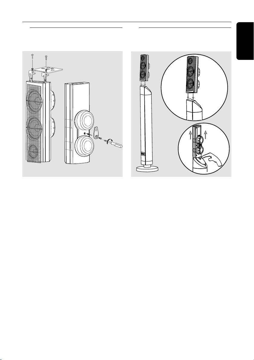
Step 1: Set up the surround
speakers
screws
mini speaker
stand
1 OR 2
1 Before connecting the speakers to the
DVD system, firmly attach the mini
speaker stands to the surround speakers
using the supplied screws.
OR
2 Alternatively, you can choose to mount
the speakers on the wall. Attach the
supplied bracket firmly to the rear of
speakers using the supplied screws. Then
mount a screw (not supplied) on the wall
where the speaker is to be hung and
hook the speaker securely onto the
mounted screw.
CAUTION!
You should get a qualified person to
attach the brackets to the wall.
DO NOT do it by yourself to avoid
unexpected damage to the
equipment or injury to personnel.
Step 2: Set up the front
speakers with the
subwoofer stands
front
speaker
1
2
subwoofer
stand
The connections between front speakers
and DVD system are through the twin
subwoofer stands.
1 Attach the left front speaker to the left
subwoofer stand and right front speaker
to the right subwoofer stand.
2 To disconnect speaker from the
subwoofer stand, press the button at the
rear of subwoofer stand while pulling up
the speaker.
Helpful Hint:
– The front speakers are labeled as
FRONT L (left) or FRONT R (right.)
English
Helpful Hint:
– The surround speakers are labeled as
REAR L (left) or REAR R (right.)
11

Connections
English
Step 3: Connecting speakers
and twin subwoofer
front speaker
with subwoofer
stand (right)
L
R
SUB-WOOFER
C
SL
SPEAKER SYSTEMS (4Ω)
SR
SURROUNDCENTER FRONT
Surround
speaker
(right)
Connect the supplied speaker systems
using the supplied speaker cables by
matching the colors of the jacks and
speaker cables. Fully insert the stripped
portion of the speaker wire into the
jacks.
Speakers / Subwoofer - +
Front Left (FL) (L) black white
Front Right (FR) (R) black red
Center (C) black green
Surround Left (SL) black blue
Surround Right (SR) black gray
Subwoofer (L) black purple
Subwoofer (R) black purple
front speaker
with subwoofer
stand (left)
Center
speaker
~ AC MAINS
L
AM
R
FM ANTENNA
AUDIO
VIDEO
OUT
AUX
IN
TVINLINE
OUT
Pr
CVBS
Pb
Y
S-VIDEO
Surround
speaker
(left)
P-SCAN
ON OFF
DIGITAL
OUT
L
R
DIGITAL
IN
Helpful Hints:
– Ensure that the speaker cables are
correctly connected. Improper connections
may damage the system due to short-circuit.
– Do not connect more than one speaker to
any one pair of
+/- speaker jacks.
– Do not connect speakers with an
impedance lower than the speakers supplied.
Please refer to the SPECIFICATIONS section
of this manual.
12

Connections
FM ANTENNA
AM
DIGITAL
OUT
DIGITAL
IN
AUX
IN
TVINLINE
OUT
AUDIO
VIDEO
OUT
CVBS
S-VIDEO
L
R
Pr
Pb
Y
1
2
SPEAKER SYSTEMS (4Ω)
SURROUND CENTER FRONT
L
R
SL
SR
C
SUB-WOOFER
➠
Step 4: Placing the speakers
and subwoofer
stands
Center speaker and
DVD system
Front speaker with
subwoofer stand
(Left)
1
3
Surround
Speaker (Left)
2
Front speaker with
subwoofer stand
For best possible surround sound, all the
speakers should be placed at the same
distance from the listening position.
1 Place the left and right front speakers
with subwoofer stands at equal distances
from the TV and at an angle of
approximately 45 degrees from the
listening position.
2 Place the center speaker above the TV or
the DVD system so that the center
channel’s sound is localized.
3 Place the surround speakers at normal
listening ear level facing each other or
mounted on the wall.
Helpful Hints:
– To avoid magnetic interference, do not
position the front speakers too close to your
TV.
– Allow adequate ventilation around the
DVD system.
(Right)
1
Surround
Speaker (Right)
Step 5: Connecting FM/AM
antennas
antenna
fix the claw
into the
slot
3
1 Connect the supplied AM loop antenna
to the AM jack. Place the AM loop
antenna on a shelf or attach it to a stand
or wall.
2 Connect the supplied FM antenna to the
FM jack. Extend the FM antenna and fix
its ends to the wall.
For better FM stereo reception, connect
an external FM antenna (not supplied.)
Helpful Hints:
– Adjust the position of the antennas for
optimal reception.
– Position the antennas as far as possible
from your TV, VCR or other radiation source
to prevent unwanted interference.
AM
FM ANTENNA
AM
FM
antenna
English
13

Connections
S
O
C
O
P-SCAN
ON OFF
Pb
DIGITAL
OUT
DIGITAL
IN
AUX
IN
TV
IN
LINE
OUT
AUDIO
VIDEO
OUT
CVBS
S-VIDEO
FM ANTENNA
AM
L
R
Y
AUDIO
OUT
Pr/Cr
Pb/Cb
Y
S-VIDEO
IN
VIDEO IN
COMPONENT
VIDEO IN
AUDIO
OUT
Pr/Cr
Pb/Cb
Y
S-VIDEO
IN
VIDEO IN
COMPONENT
VIDEO IN
2
1
3
Pr
SURROUND CENTER FRONT
L
R
SL
SR
C
SUB-WOOFER
English
Step 6: Connecting TV
COMPONENT
VIDEO IN
S-VIDEO
IN
AUDIO
OUT
COMPONENT
VIDEO IN
S-VIDEO
IN
Pr/Cr
AUDIO
OUT
Pb/Cb
VIDEO IN
Y
L
NT
R
SUB-WOOFER
C
ENTER FR
SL
UND
URR
SR
DIGITAL
DIGITAL
AM
FM ANTENNA
AUDIO
TV
LINE
AUX
OUT
IN
OUT
IN
L
R
IN
2
IMPORTANT!
– You only need to make
connection from the following
options, depending on the
capabilities of your TV system.
– Connect the DVD system directly
to the TV.
VIDEO IN
1
VIDEO
OUT
CVBS
Pb
Y
S-VIDEO
one video
Pr/Cr
Pb/Cb
Y
P-SCAN
ON OFF
3
IMPORTANT!
– Component Video connection
provides higher picture quality. This
option must be available on your TV.
– The progressive scan video
quality is only possible through
Component Video (Pr Pb Y) output.
Using Composite Video jack
(CVBS)
1 Use the composite video cable (yellow)
to connect the DVD system’s CVBS jack
to the video input jack (or labeled as A/V
In, Video In, Composite or Baseband) on
the TV.
2 To hear the TV channels through this
DVD system, use the audio cables (white/
red) to connect TV IN (L/R) jacks to the
corresponding AUDIO OUT jacks on the
TV.
3 Set the P-SCAN switch to ‘OFF.’
Using Component Video jacks
(Pr Pb Y)
1 Use the component video cables (red/
blue/green) to connect the DVD system’s
Pr Pb Y jacks to the corresponding
Component video input jacks (or labeled
as Pr/Cr Pb/ Cb Y or YUV) on the TV.
2 To hear the TV channels through this
DVD system, use the audio cables (white/
red) to connect TV IN (L/R) jacks to the
corresponding AUDIO OUT jacks on the
TV.
3 If you are using a Progressive Scan TV (TV
must indicate Progressive Scan or
14
ProScan capability) set the P-SCAN
switch to ‘ON.’ Otherwise, set it to
‘OFF.’

Connections
Pb
DIGITAL
OUT
DIGITAL
IN
AUX
IN
TVINLINE
OUT
AUDIO
VIDEO
OUT
CVBS
S-VIDEO
FM ANTENNA
AM
L
R
Pr
Y
AUDIO IN
R L
VIDEO
IN
TO TVINT IN
CH3 CH4
1
3
2
SPEAKER SYSTEMS (4Ω)
SURROUND CENTER FRONT
L
R
SL
SR
C
SUB-WOOFER
P-SCAN
ON OFF
COMPONENT
VIDEO IN
S-VIDEO
IN
VIDEO IN
Pr/Cr
Pb/Cb
Y
AUDIO
OUT
COMPONENT
VIDEO IN
S-VIDEO
IN
Pr/Cr
AUDIO
OUT
Pb/Cb
VIDEO IN
Y
1
L
R
SUB-WOOFER
C
SL
SR
SURROUND CENTER FRONT
DIGITAL
DIGITAL
AM
FM ANTENNA
AUDIO
VIDEO
OUT
TV
LINE
AUX
OUT
IN
IN
L
R
IN
2
Pr
CVBS
OUT
Pb
P-SCAN
ON OFF
Y
S-VIDEO
3
IMPORTANT!
– S-Video connection provides
better picture quality. This option
must be available on your TV.
Using S-Video jack
1 Use the S-video cable (not supplied) to
connect the DVD system’s S-VIDEO
OUT jack to the S-Video input jack (or
labeled as Y/C or S-VHS) on the TV.
2 To hear the TV channels through this
DVD system, use the audio cables (white /
red) to connect TV IN (L/R) jacks to the
corresponding AUDIO OUT jacks on the
TV.
3 Set the P-SCAN switch to ‘OFF.’
RF coaxial cable to TV
Back of RF Modulator
(example only)
Antenna or
Cable TV signal
IMPORTANT!
– If your TV only has a single
Antenna In jack (or labeled as 75
ohm or RF In,) you will need an RF
modulator in order to view the DVD
playback on the TV. See your
electronics retailer or contact
Philips for details on RF modulator
availability and operations.
Using an accessory RF modulator
1 Use the composite video cable (yellow)
to connect the DVD system’s CVBS jack
to the video input jack on the RF
modulator.
2 Use the RF coaxial cable (not supplied) to
connect the RF modulator to your TV’s
RF jack.
3 Set the P-SCAN switch to ‘OFF.’
English
15

Connections
English
Step 7: Connecting the
power cord
AM
FM ANTENNA
AUDIO
VIDEO
OUT
DIGITAL
OUT
L
R
DIGITAL
IN
Pr
TVINLINE
AUX
CVBS
OUT
IN
Pb
P-SCAN
ON OFF
Y
S-VIDEO
COMPONENT
VIDEO IN
S-VIDEO
IN
Pr/Cr
AUDIO
OUT
~ AC MAINS
Pb/Cb
VIDEO IN
Y
After everything is connected
properly, plug in the AC power cord
to the power outlet.
Never make or change any connections
with the power switched on.
On the DVD system,
"AUTO INSTALL – PRESS PLAY"
may appear on the display panel. Press
ÉÅ on the front panel to store all
available radio stations or press Ç to
exit (see page 41 “Tuner Operations”.)
~ AC MAINS
power outlet
AUTO INSTALL - PRESS PLAY
ISC CHANGER
16
PLAY• PAUSE
DVD VIDEO DIGITAL SURROUND SYSTEM
STOPPLAY•PAUSE SEATING
SEARCH
PROG TUNING CLOCK•TIMER
SOURCE
SURROUND
T
N
R
E
E
C
S
C
I
D
R
I
T
G
F
H
E
DVD
T
L
S
R
U
-
R
R
-
U
L
S
S
B
U
TREBLE
VOLUME
BASS
 Loading...