

Philips MX-5000-D Service manual
DVD Surround Receiver
MX5000D/22S/37S
Service
Service
Service
Service Manual
TABLE OF CONTENTS
Location of pc boards .................................................1-2
Technical Specifications ............................................. 1-3
Measurement setup ....................................................1-4
Service Aids, Safety Instruction, etc. .........................1-5
Repair Instructions ......................................................... 2
Disassembly Instructions & Service positions .............. 3
Set Block & Wiring diagram ........................................... 4
Digital Board .................................................................. 5
Front Board (Include headphone board) ....................... 6
Main, Audio-I/O, Video-I/O & Connect Boards .............. 7
DVD Module (including Service Mode
& Firmware upgrade) ............................... 8
Power Amplifier Module................................................. 9
Set Mechanical Exploded view & parts list ................. 10
History .......................................................................... 11
©
Copyright 2002 Philips Consumer Electronics B.V. Eindhoven, The Netherlands
All rights reserved. No part of this publication may be reproduced, stored in a retrieval system or
transmitted, in any form or by any means, electronic, mechanical, photocopying, or otherwise
without the prior permission of Philips.
Published by KC 0226 Service Audio Printed in The Netherlands Subject to modification
Page
CLASS 1
LASER PRODUCT
GB
3139 785 30252
Version 1.2
1-2
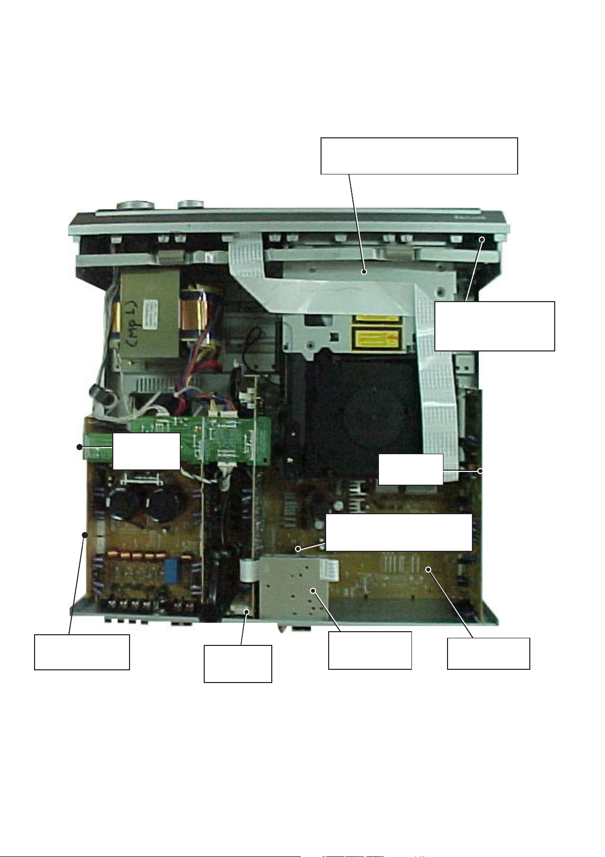
LOCATION OF PC BOARDS
Front Board
(include Headphone
Board)
Connect
Board
DVD Mechanism Loader
(The lower part : DVD Main Board)
Power Amplifier
Module
Audio - I/O
Board
Tuner Module
Board
Video-I/O board
(below the Tuner Module)
Main(Mother)
Board
Digital
Board

1-3
SPECIFICATIONS
AMPLIFIER SECTION
Output power (6, 1kHz, 10%THD, 100W)
Stereo (Front left/right) : 2 x 100W/2 x 90W FTC
Output power (6, 1kHz, 10%THD, 100W)
Front left/right : 2 x 100W
Center : 100W
Surround left/right : 2 x 100W
Subwoofer : 100W
Total Harmonic Distortion: 10% at rated power 100W(1kHz)
Signal to Noise Ratio
Stereo TV > 67 dB (IHF-A)
Surround front/center/rear > 65 dB (IHF-A, -20 dB FS)
Frequency Response 10Hz-20kHz, -3dB/+1dB
Tone Control ±10 dB
Input Sensitivity 450 mV/ 47 Kohm
Output level 420 mV/ 1 Kohm
Cross-talk (separation)
Stereo TV(line) > 55 dB
Dolby Digital > 45 dB
TUNER SECTION
Tuning Range
- 37 version : FM 87.5-108MHz(100kHz steps)
AM 530-1700kHz (10kHz steps)
- 22 version : FM 87.5-108MHz (50kHz steps)
AM 531-1602kHz (9kHz steps)
26dB Quieting Sensitivity FM < 22 dBf
AM < 3250 µV/m
Harmonic Distortion (15kHz LPF on) FM Mono < 3%
FM Stereo <2%
Signal to Noise Ratio FM Mono > 60 dB
FM Stereo > 60 dB
AM > 40 dB
Frequency Response FM 20 Hz-15 kHz, -3 dB
Selectivity AM > 25 dB
DVD SECTION
Laser Type Semiconductor
Disc Diameter 12cm / 8cm
Video Decoding MPEG-2
Video DAC 10 Bits
Video Format 4:3/ 16:9
Video S/N > 45 dB (minimum)
Input sensitivity 1.0Vpp / 75
Out put level 1.0Vpp / 75
S-Video Output Y - 1.0V(p-p), 75
C - 286 mVp-p, 75
SCART Output R- 700mVp-p, 75
(-22 Version only) G- 700mVp-p, 75
B- 700mVp-p, 75
Frequency Response 20 Hz - 20 kHz (44.1 kHz)
20 Hz - 22 kHz (48 kHz)
20 Hz - 44 kHz (96 kHz)
MP3-CD FORMAT
- Suported Bit-rates : 32, 48, 64, 128, 160, 192, 256, 320 (kbps)
(Can not Scan between 32 to 64Kbps.)
- Suported VBR(variable bitrate) Bit-rate
- Sampling frequece : 44.1kHz
- Suported File name : *.mp3 (Max. 10 charaters)
- Recording Format
File Type : ISO9660
Write Format : MODE 1 (CD-ROM)
Max Multisession : 5 ( recommend only session 1)
NOTE: set can read other type format, but we can't guaran-
tee.
MISCELLANEOUS
Power Supply Rating 230V / 50 Hz(-22 Version)
120V / 60 Hz(-37 Version)
Power Consumption 3.4A(1/8W), 690W max(Before clip)
Dimensions (w x h x d) 430mm x 140mm x 400mm
Weight 16.7 kg
IR REMOTE CONTROL
Effective Range > 8 Meter
Number of Keys 51
Battery (1.5V) AA x 2
SPEAKERS (front/ center/ surround)
Front Speakers
System 3-way shielded
Impedance 6
Speaker drivers 3" woofer, 1.75" tweeter
Dimensions (w x h x d) 94mm x 155mm x 88mm
Weight 0.45 kg
SUBWOOFER
Subwoofer (not magnetically shielded design 6.5"
Output power 100W(6, DIN)
THD 10% at 55 Hz
Reproduction frequency response 35 Hz - 150 Hz
Dimensions (w x h x d) 200mm x 310mm x 370mm
Weight 7 kg
Specifications subject to change without prior notice
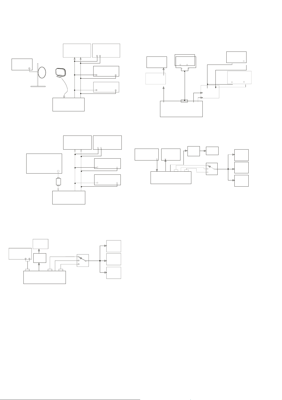
1-4
AM LOOP
ANT
LOOP
AM/FM SSG
OUT
LOAD
8 OHM
SCOPE
2 CH
AC LEVEL METER
DISTORTION
METER
2 CH
AM ANT
FL
FR
DUT
2 CH
L
R
Tuner AM Band
SSG=Standard Signal Generator
AUDIO STEREO
GENERATOR
SCOPE
AC
LEVEL
METER
FL
FR
DUT
C
SL
SR
SUB
OUT
SWITCH
LOAD
6 OHM
LEVEL
DISTORTION
METER
SCOPE
2 CH
SL/SR
CENTER
FL/FR
Balance EQ Power
L
R
L
R
IN
2 CH
CD/DVD/C-VIDEO OUTPUT
NTSC/PAL
VIDEO SIGNAL
GENERATOR
SCOPE
AC
LEVEL
METER
SCOPE
FL
FR
DUT
C
SL
SR
SUB
OUT
SWITCH
LOAD
6 OHM
LEVEL
DISTORTION
METER
SCOPE
2 CH
2 CH
SL/SR
CENTER
FL/FR
C-VIDEO IN
MONITOR
REC OUT
VIDEO
Tuner FM Band
AM/FM STEREO
SSG
OUT
LOAD
6 OHM
SCOPE
2 CH
AC LEVEL METER
DISTORTION
METER
2 CH
FM ANT
FL
FR
DUT
2 CH
PADHEAD
L
R
SSG=Standard Signal Generator
S-Video/Scart/Digital Output
SCOPE
L
DTS
DECODER
AC LEVEL
METER
AC LEVEL
METER
UL/S-VIDEO
CE/SCART
REC
OUT
DIGITAL
OUT
DUT
AC METER LEVEL
2 CH
R
SCOPE
L
R
2 CH
OPT
COAX
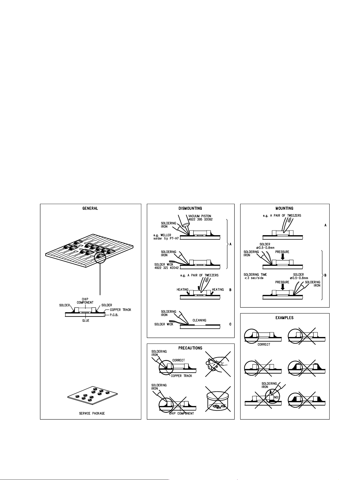
1-5
HANDLING CHIP COMPONENTS
SERVICE AIDS
Service Tools:
Universal Torx driver holder .................................. 4822 395 91019
Torx bit T10 150mm ............................................. 4822 395 50456
Torx driver set T6 - T20 ......................................... 4822 395 50145
Torx driver T10 extended ...................................... 4822 395 50423
ESD Equipment:
Anti-static table mat - large 1200x650x1.25mm ... 4822 466 10953
Anti-static table mat - small 600x650x1.25mm ..... 4822 466 10958
Anti-static wristband .............................................. 4822 395 10223
Connector box (1MΩ) ............................................ 4822 320 11307
Extension cable
(to connect wristband to conn. box) .................. 4822 320 11305
Connecting cable
(to connect table mat to conn. box) .................. 4822 320 11306
Earth cable (to connect product to mat or box) .... 4822 320 11308
Complete kit ESD3
(combining all above products) ......................... 4822 320 10671
Wristband tester .................................................... 4822 344 13999
1-6
GB
WARNING
All ICs and many other semi-conductors are
susceptible to electrostatic discharges (ESD).
Careless handling during repair can reduce life
drastically.
When repairing, make sure that you are
connected with the same potential as the mass
of the set via a wrist wrap with resistance.
Keep components and tools also at this
potential.
F
ATTENTION
Tous les IC et beaucoup d autres
semi-conducteurs sont sensibles aux
d charges statiques (ESD).
Leur long vit pourrait tre consid rablement
court e par le fait qu aucune pr caution n est
prise leur manipulation.
Lors de r parations, s assurer de bien tre reli
au m me potentiel que la masse de l appareil et
enfiler le bracelet serti d une r sistance de
s curit .
Veiller ce que les composants ainsi que les
outils que l on utilise soient galement ce
potentiel.
ESD
D
WARNUNG
Alle ICs und viele andere Halbleiter sind
empfindlich gegen ber elektrostatischen
Entladungen (ESD).
Unsorgf ltige Behandlung im Reparaturfall kan
die Lebensdauer drastisch reduzieren.
Veranlassen Sie, dass Sie im Reparaturfall ber
ein Pulsarmband mit Widerstand verbunden
sind mit dem gleichen Potential wie die Masse
des Ger tes.
Bauteile und Hilfsmittel auch auf dieses gleiche
Potential halten.
NL
WAARSCHUWING
Alle IC s en vele andere halfgeleiders zijn
gevoelig voor electrostatische ontladingen
(ESD).
Onzorgvuldig behandelen tijdens reparatie kan
de levensduur drastisch doen verminderen.
Zorg ervoor dat u tijdens reparatie via een
polsband met weerstand verbonden bent met
hetzelfde potentiaal als de massa van het
apparaat.
Houd componenten en hulpmiddelen ook op
ditzelfde potentiaal.
I
AVVERTIMENTO
Tutti IC e parecchi semi-conduttori sono
sensibili alle scariche statiche (ESD).
La loro longevit potrebbe essere fortemente
ridatta in caso di non osservazione della pi
grande cauzione alla loro manipolazione.
Durante le riparazioni occorre quindi essere
collegato allo stesso potenziale che quello della
massa dell apparecchio tramite un braccialetto
a resistenza.
Assicurarsi che i componenti e anche gli utensili
con quali si lavora siano anche a questo
potenziale.
Pour votre s curit , ces documents
doivent tre utilis s par des sp cialistes agr s, seuls habilit s r parer
votre appareil en panne .
GB
Safety regulations require that the set be restored to its original
condition and that parts which are identical with those specified,
be used.
NL
Veiligheidsbepalingen vereisen, dat het apparaat bij reparatie in
zijn oorspronkelijke toestand wordt teruggebracht en dat onderdelen,
identiek aan de gespecificeerde, worden toegepast.
F
Les normes de s curit exigent que l appareil soit remis l tat
d origine et que soient utilis s les pi ces de rechange identiques
celles sp cifi es.
D
Bei jeder Reparatur sind die geltenden Sicherheitsvorschriften zu
beachten. Der Original zustand des Ger ts darf nicht ver ndert werden;
f r Reparaturen sind Original-Ersatzteile zu verwenden.
I
Le norme di sicurezza esigono che l apparecchio venga rimesso
nelle condizioni originali e che siano utilizzati i pezzi di ricambio
identici a quelli specificati.
"After servicing and before returning set to customer perform a
leakage current measurement test from all exposed metal parts to
earth ground to assure no shock hazard exist. The leakage current
must not exceed 0.5mA."
CLASS 1
LASER PRODUCT
3122 110 03420
GB
Warning !
Invisible laser radiation when open.
Avoid direct exposure to beam.
S
Varning !
Osynlig laserstr lning n r apparaten r ppnad och sp rren
r urkopplad. Betrakta ej str len.
SF
Varoitus !
Avatussa laitteessa ja suojalukituksen ohitettaessa olet alttiina
n kym tt m lle laseris teilylle. l katso s teeseen!
DK Advarse !
Usynlig laserstr ling ved bning n r sikkerhedsafbrydere er
ude af funktion. Undg udsaettelse for str ling.

2-1
Check to Input BD
CN 11, data line
pin 1, 2, 3, 4
Yes
Check to Tuner BD
power supply
Tuner no
output
Audio output
No sound
No
Ye
Yes
Yes
s
A
Yes
Yes
No
No
No
No
MX5000D REPAIR CHART
Possible Tuner
Modual bad cause
Possible
IC 83
bad cause
Check
IC83
Repair/ Replace
DVD Main BD
DVD Audio
No output
Check Digital BD
BN42, SPDIF
pin 2
All Channel
No output
Check the power
and connect boards
input function DVD/
SAT-OPT?
input function
Analog?
Check Digital BD
BN41, Pin 1,3,5,7,9,11
Analog signal
Check Input BD
BN51, Pin 1,3,5,7,9,11
Analog signal
Check
Volume/ IC 19
Q179
C=OV?
Check
IC 28
Check Main BD
IC 28
Check Connent BD
BN51, Pin 1,3,5,7,9,11
Analog signal
Yes
See the page 9-2
Voltage Table
No
Possible
IC28 bad cause

2-2
B C
SCART(EUR-22 Version
Only) NO Output
Check Main BD
BN10, pin9, 18, 19,20
CVBS, R, G, B
Signal
No
Check DVD Main BD
CN10, pin9, 18, 19, 20
page 2-5, 2-6
figure 4-a, b, c, d
No
DVD out (S-VIDEO)
No output
Check Input BD
BN35, pin10, 11
Y,C Signal
No
Check input BD
CN10, pin5, 7
Y,C Signal
No
Video Output
No signal
Yes
Monitor out
No output
Check input BD
IC35, pin10
No
Check input BD
BN35, pin9
No
Check Input BD
CN10, pin9
No
Check the DVD
Main BD
No
Change
DVD Main BD
Yes
Yes
No Sound No
picture
All Channel output
No signal
Check power
connect all boards
Check Main board
CN10, pin1
reset
No
Check IC83,
host micom
No
Possible
IC83 bad cause
Possible
IC 14
bad cause
Change
DVD Main BD
No
Check DVD Main BD
IC14, pin47, 48
Y,C Signal
Yes
Check the
page 2-6, figure 4-e,
and 4-f
Check DVD Main BD
IC14, pin44
Yes
Check the
page 2-6, figure 4-d
No
Change
DVD Main BD

2-3
E
Check the Disc
for dust or damage
Check DVD Loader
power supply: 5V, 12V
Check DVD BD HX1
Check DVD main BD
CN10, pin1=H
Yes
Yes
Yes
Possible DVD Main BD damage
Replace DVD BD
Possible DVD Loader damage
Replace Loader & test again
No
Yes
No
Repair power supply circuit
Change to other Disc
Cannot read the disc
or Intermittent
Check the Disc
is off center or not
Yes
D
Mechanical noise
during playing disc
Reset the Disc
into the center
Check is there
something inside the
DVD Loader or not
Yes
Open the tray
& check it out
No
No
Possible DVD Loader damage
Replace the DVD Loader
MX5000D Repair Chart
DVD Section
FB
Video output
No Signal
(see page 10-2)
No Sound
Digital no output
D
E
Cannot read
Disc or
Intermittent
Mechanical
Noise
C
No sound &
picture
(see page 10-2)
MX5000D REPAIR CHART - DVD SECTION

F
No Sound
Digital no output
2-4
Check(figure 5) DVD Main BD
IC07, pin6
No
Check DVD Main BD
IC07, pin1(Reset)
page 2-6, figure 5
No
Possible IC01 damage
Replace DVD BD
Yes
Possible Optical damage
or connection cable damage
Yes
Change IC07
2-5
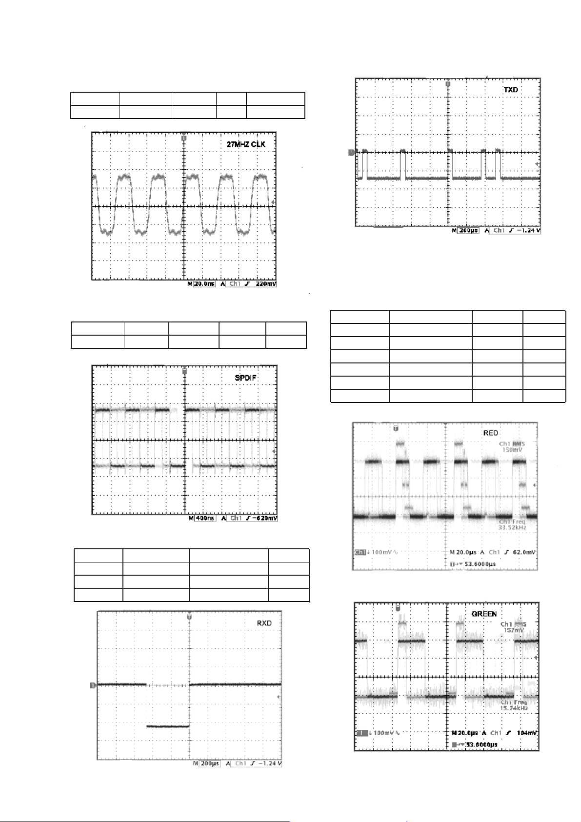
ADDITIONAL INFORMATION FOR DVD SECTION
1. Clock Check
Clock name Test point Frequency Figure Remarks
27MHz IC07 (Pin10) 27MHz 1
Figure 1
4. Video Output Check Playback TDV540 Color Bar
2. DVD Audio Clock Audio Test Signal
Test name
SPDIF 41 after R261 PLAY 2
IC01
Test point Condition Figure
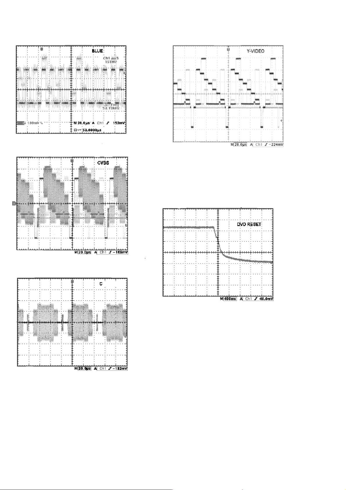
Test name Test point Condition Figure
RED OUT CN10 (Pin20)
GREEN OUT PLAY 4-b
BLUE OUT PLAY 4-c
CVBS OUT PLAY 4-d
C OUT PLAY 4-e
Y OUT PLAY 4-f
Figure 3-b
PLAY 4-a
CN10 (Pin19)
CN10 (Pin18)
CN10 (Pin9)
CN10 (Pin7)
CN10 (Pin5)
Figure 2
3. Control In / Out
Test name Test point Condition Figure
RXD CN10 (Pin7)
TXD FUNCTION PRESS 3-b
CN10 (Pin16)
FUNCTION PRESS 3-a
Figure 3-a
Figure 4-a (EUR only)
Figure 4-b EUR only)
2-6
Figure 4-c (EUR only)
Figure 4-d (EUR only)
5. DVD Reset (fig. 5)
CN10 : Pin1 (reset pont)
Figure 4-f
Figure 4-e
Figure 5
DISMANTLING INSTRUCTIONS
3-1
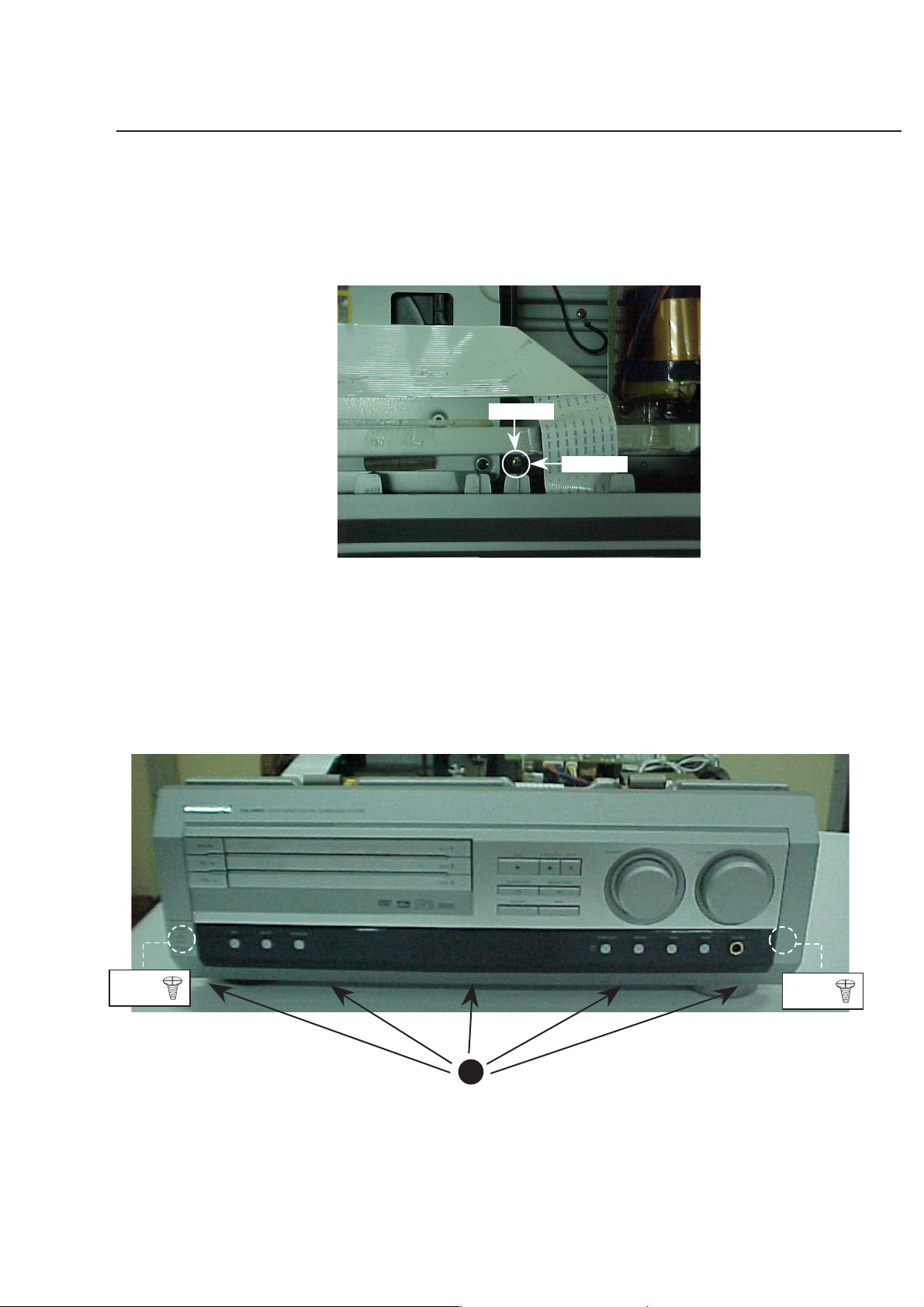
Dismantling of the Front Panel Assembly
1) Loosen 13 screws and remove the
2) Loosen 1 screws C1 Pull out holder C2. (see figure1)
Top Cover by lifting the
rear portion upwards before sliding it out towards the rear
.
- 7 screws on the rear
- 6 screws each on the left & right side
3) Loosen 5 screws A and each side 2 screws A-1 for
wire tags & cut 2 wire ties, then remove the front
pannel. (see figure2)
Figure 2
A
Figure 1
Screw(C1)
holder(C2)
A-1
A-1
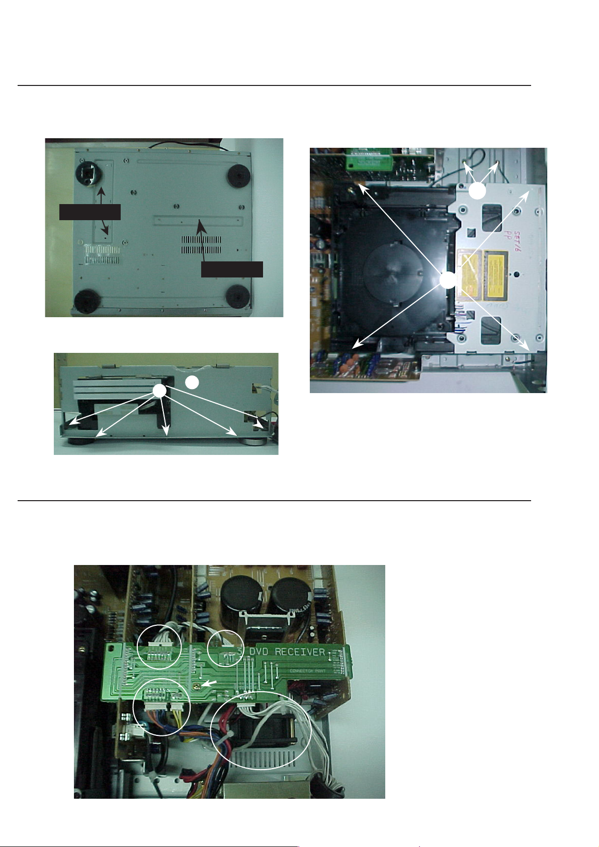
Dismantling of the DVD Module / shield bracket B1
1) Loosen screws D3 of botton chassis figure3.
Screw K1
Screw D3
Figure 3
3-2
2) Loosen 5 screws B and remove the B1. (figure 4)
3) Loosen 4 screws D (see figure 5) and 2 screws D1,
then all connectors to remove the DVD module.
D1
D
B
B1
Figure 4
Dismantling the Power Amplifier Module
1) Pull out connected wires and Loosen 1 screws (see figure 6).
Figure 5
2) Loosen 10 screws on the Rear Panel
- 4 screws K for the Speaker sockets (see figure7)
- 4 screws K for the heat sink.
- 2 screws K1 for the bottom chassis.(see figure 3)
Figure 6
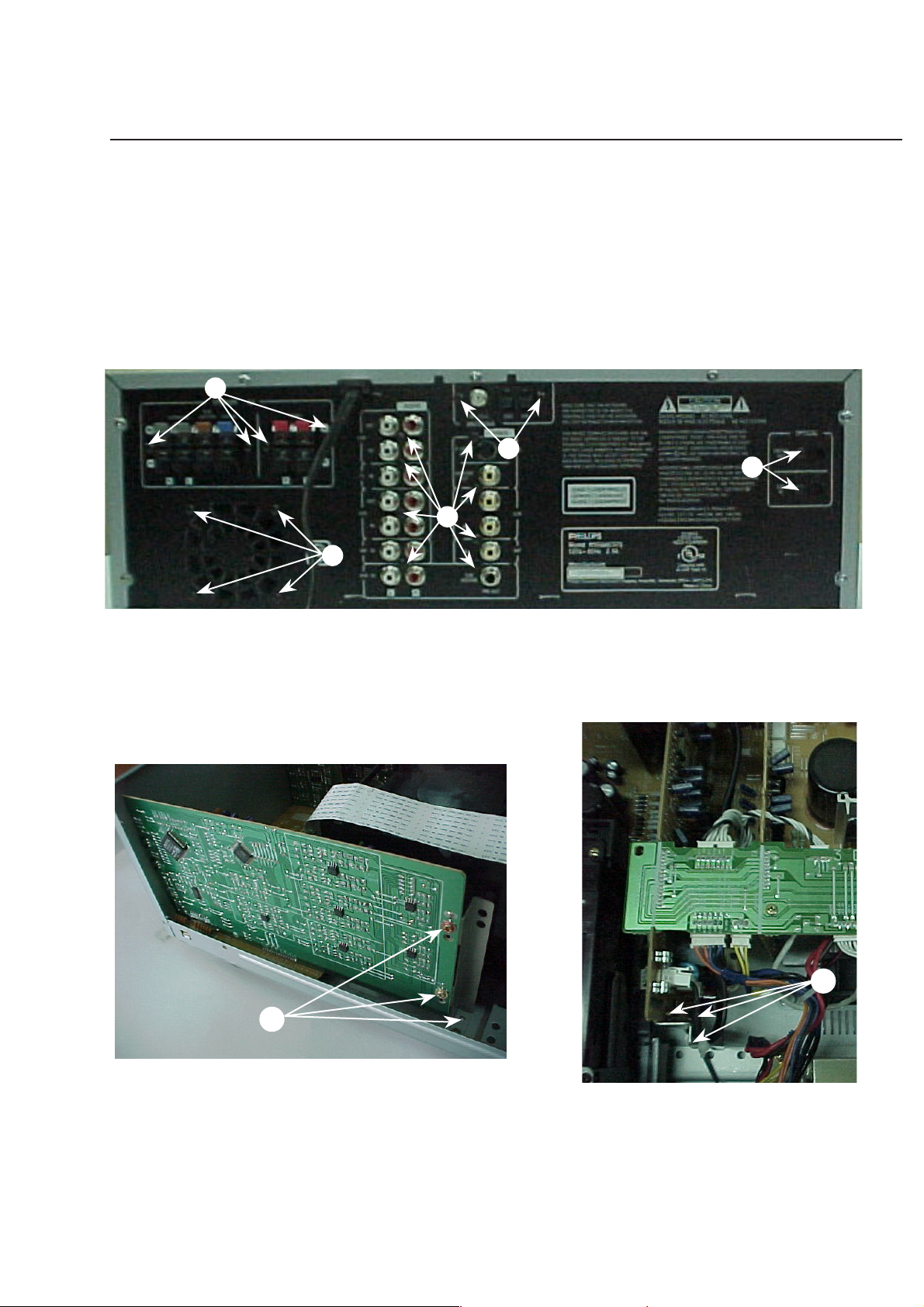
3-3
1) Loosen 2 screws E on the Rear panel to remove the Tuner
Module.
2) Loosen 2 screws F on the Rear panel and Loosen 3 screws
F1 (figure8) to remove the Digital Board.
3) Loosen 8 screws G on the Rear panel and Loosen 3 screws
G1 (figure9) to remove the Audio-I/O, Video-I/O Board.
Dismantling the Tuner, Audio - I/O Video - I/O and Digital Boards. (Refer figure 7)
Figure 7
Figure 9Figure 8
K
K
F
E
G
G1
F1
3-4
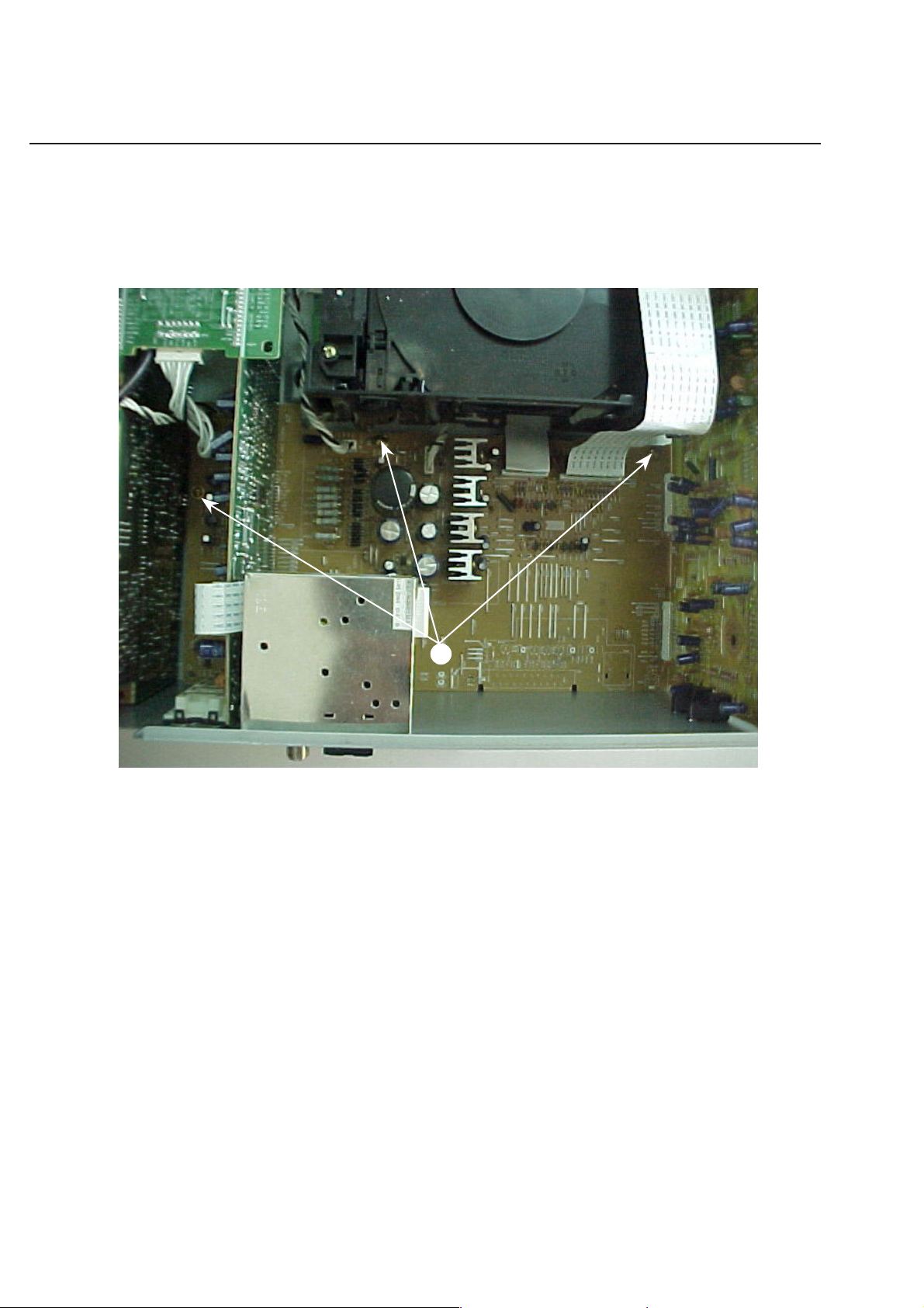
Dismantling the Main(Mother) Boards. (Refer figure 10)
Loosen 3 screws H on the bottom chassis then remove the board.
H
Figure 10
3-5 3-6
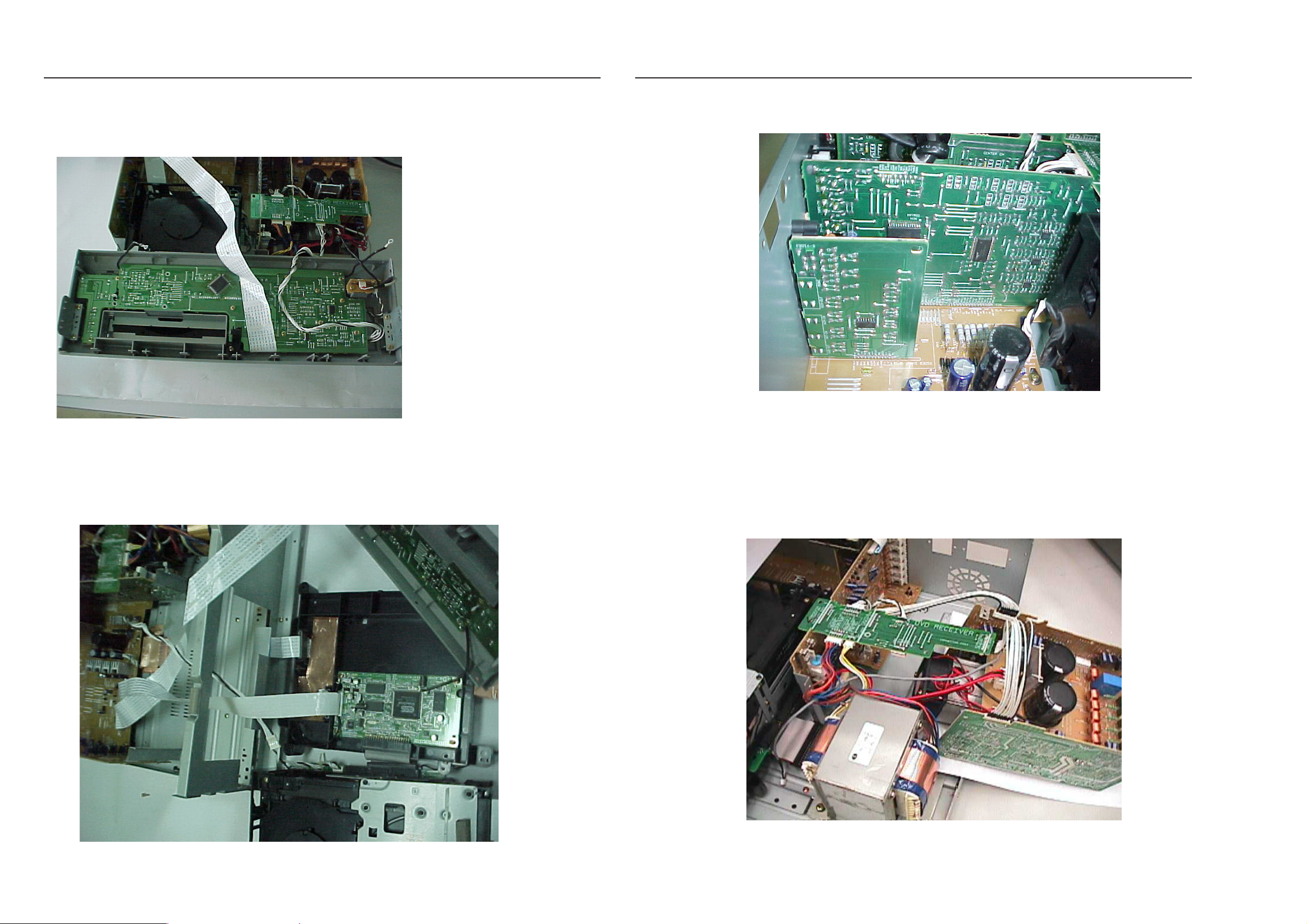
SERVICE POSITIONS & REPAIR HINTS
Service pos A
SERVICE POSITIONS & REPAIR HINTS
Service pos C
No
te: In some service positions the components or copper
patterns of one board may risk touching its neigh-
bouring pc boards or metallic parts. To prevent such
short-circuit use a piece of hard paper or other
insulating material between them.
Service pos B
Service pos D
Note: Use service cable "9965 000 15831" to connect the Power Amplifier Module
4-1
4-2
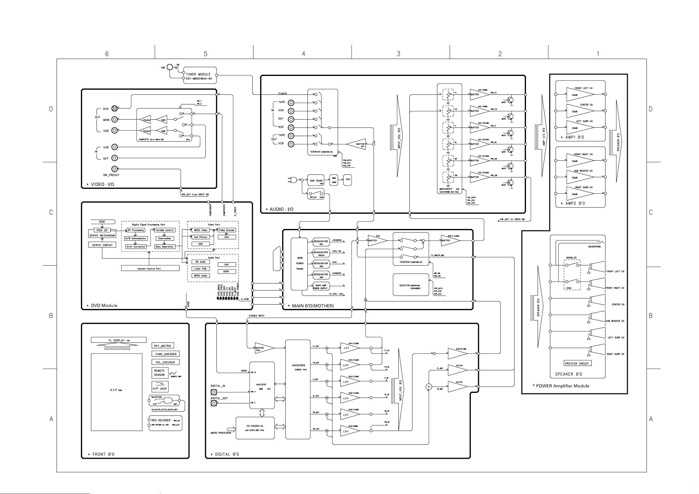
SET BLOCK DIAGRAM
R
G
B
CVBS
(-22 Version
SCART-OUT)
CVBS
R
G
B
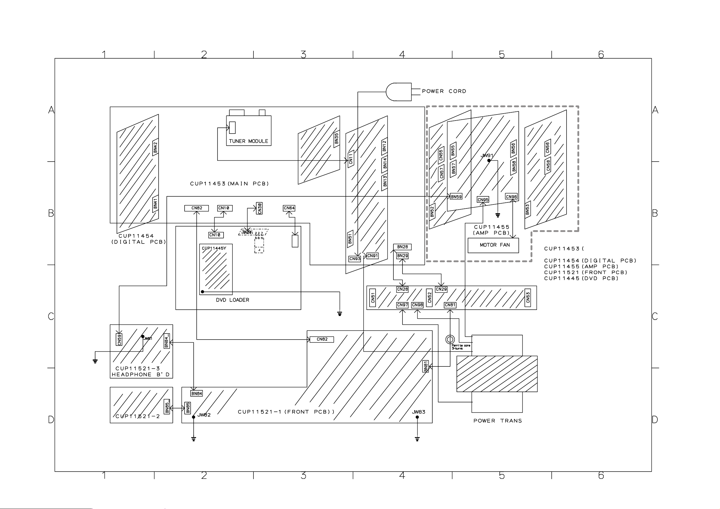
SET WIRING DIAGRAM
4-3 4-4
Main(Mother) BOARD
AUDIO
I-O BOARD
AMPIFIER MODULE
VIDEO I-O BOARD
MOTHER/ AUDIO-I/O
VIDEO-I/O PCB)
DVD LOADER + FRONTEND SERVO BOARD
 Loading...