

Page 1
Installation Guide
Philips MP2/MP5 Roll Stand
The purpose of this guide is to:
1. Describe assembly of Roll Stand (pages 2 – 3).
2. Describe attachment of Fixed Tilt Mounts (page 4).
3. Describe mounting MP5 on Roll Stand (page 5).
4. Describe mounting MP2 on Roll Stand (page 6).
5. Describe cable management – MP2 only (page 7).
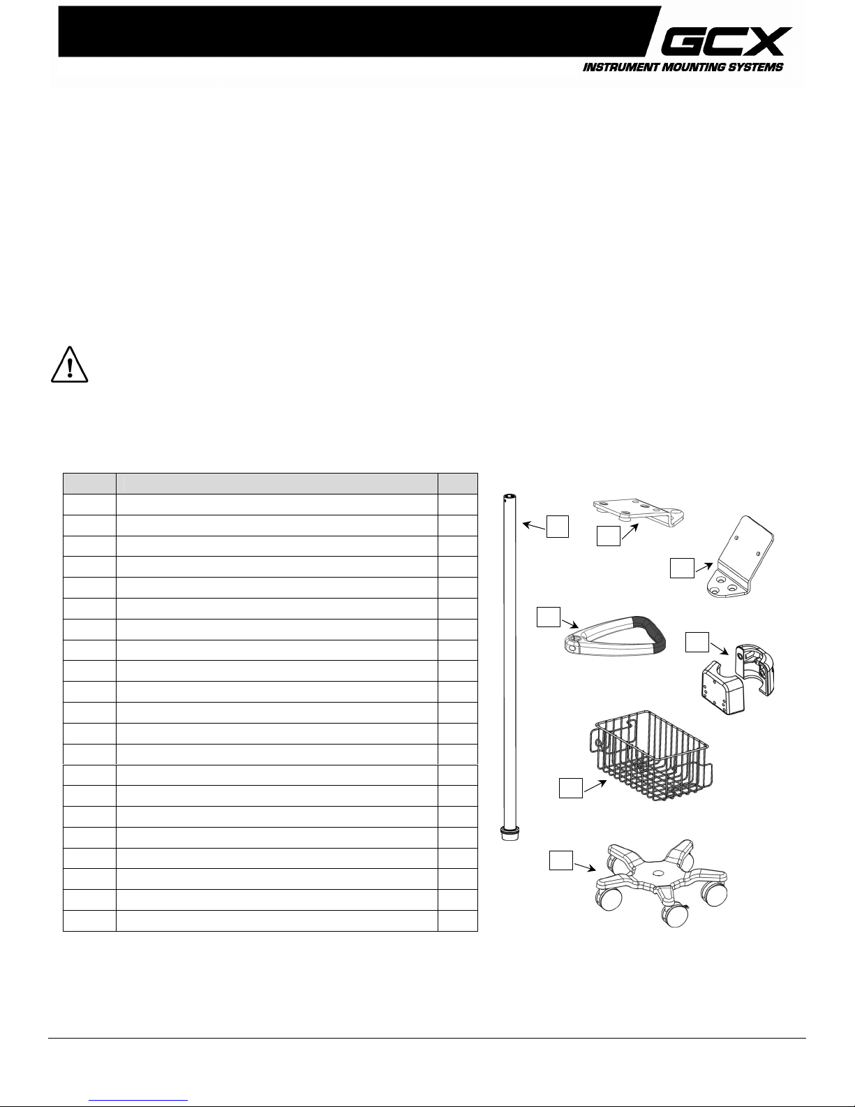
Parts Reference
The following parts and hardware are included with this installation kit (hardware not shown):
Tools Required: Phillips screwdriver (not provided), 1/2'' [13mm] wrench (not provided).
WARNING: USE OF THIS ROLL STAND FOR INSTRUMENTS OTHER THAN THOSE DESCRIBED IN
THIS DOCUMENT MAY RESULT IN INJURY DUE TO TIPPING OF THE ROLL STAND. THE CUSTOMER
SHOULD VERIFY THE STABILITY OF ANY DEVIATION FROM THE CONFIGURATIONS SHOWN.
Item # Description Qty
1 Post, 40'' 1
2 Base, 21'' 1
3 5/16-18 x 1'' Hex Head Cap Screw (HHCS) 1
4 5/16 Flat Washer 1
5 5/16 Split Lock Washer 1
6 Utility Basket 1
7 Basket Clip 2
8 #8-32 x 7/8'' Pan Head Machine Screw (PHMS) 2
9 #8-32 Hex Nut 2
10 Handle 1
11 #10-32 x 9/16'' PHMS 4
12 Fixed Tilt Mount, MP5
13 Fixed Tilt Mount, MP2 1
14 M4 x 14mm PHMS 2
15 #10-32 x 3/4'' Flat Head Machine Screw (FHMS) 3
16 Power Supply Mount 1
17 M4 x 12mm PHMS 2
18 M6 x 10mm FHMS 3
19 M6 x 8mm PHMS 2
20 Cable Clip (not shown – see page 7) 2
21 Screw Cover, Adhesive-backed Lexan 1
1
12
10
6
2
13
16
DU-PH-0062-60 Rev A 7/16/07 GCX Corp Page 1 of 7
Page 2
Assembling the Roll Stand
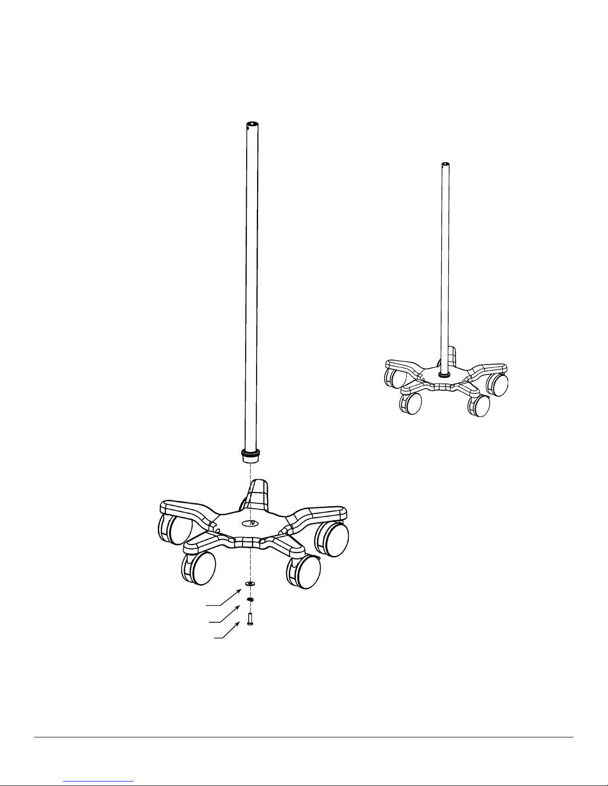
1. Insert bottom end of Post in center of Base and lay assembly on its side for access to bottom of base (not shown).
2. Using a 1/2'' [13mm] wrench, fasten Post to Base with one (1) 5/16-18 x 1'' HHCS, with 5/16 split lock washer, and
5/16'' flat washer as shown below. Return Roll Stand to upright position.
5/16 Flat Washer
5/16 Lock Washer
5/16-18 x 1'' HHCS
DU-PH-0062-60 Rev A 7/16/07 GCX Corp Page 2 of 7
Page 3
Attaching Utility Basket and Handle to Roll Stand Post
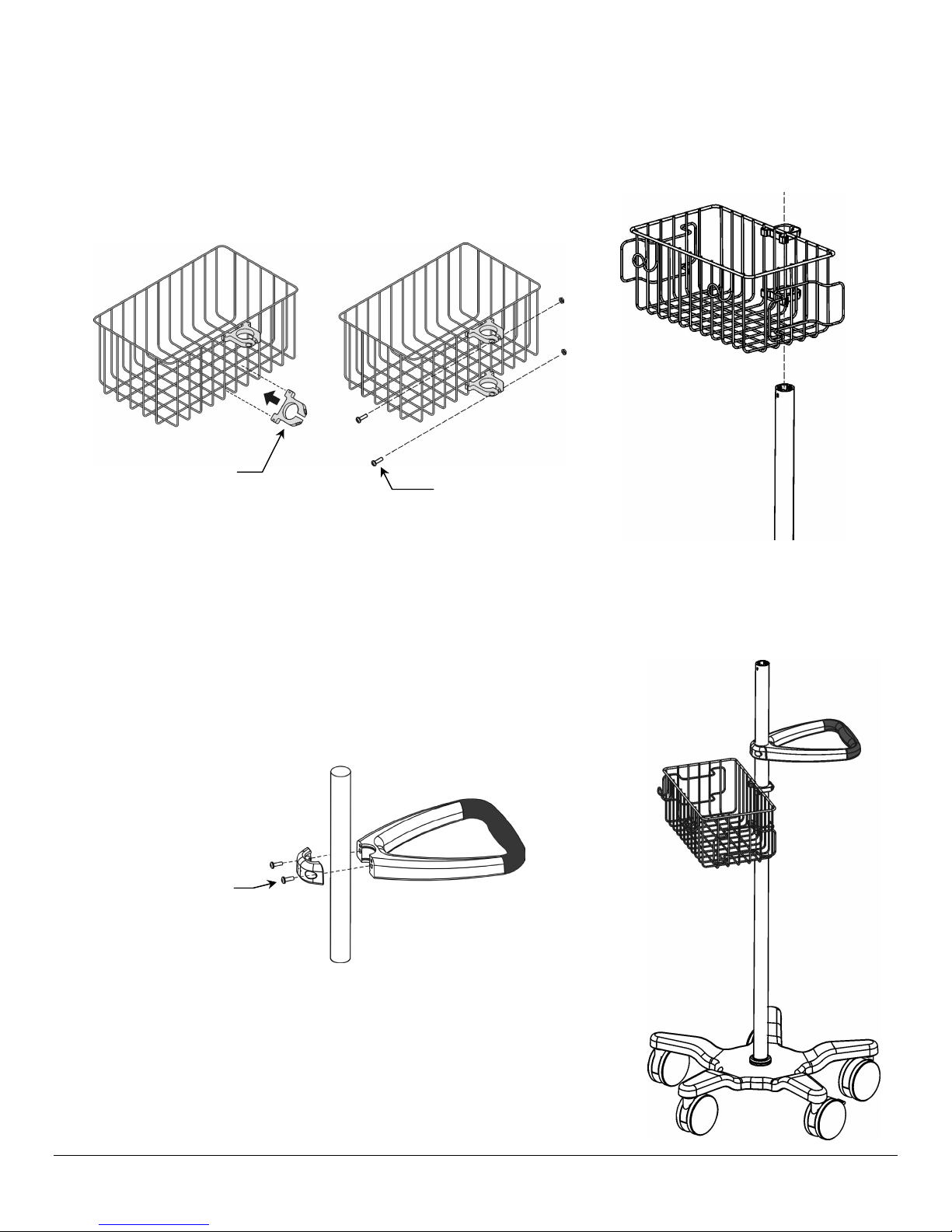
1. Attach two (2) Basket Clips to Utility Basket as shown below left. Insert two (2) #8-32 x 7/8'' PHMS and #8-32 hex nuts
in Basket Clips but do not tighten.
2. Slide Basket Clips over top end of Roll Stand Post (below right) and move Basket to mounting position. Do not tighten
screws at this time. Basket may require re-alignment after the Fixed Tilt Mount is attached.
Basket Clips
#8-32 x 7/8'' PHMS (2)
#8-32 Hex Nuts (2)
3. Position the Handle below the top of the Roll Stand Post opposite the Basket. Fasten Handle to Post with two (2) #1032 x 9/16'' PHMS as shown, but do not tighten at this time. Handle may require re-alignment after the Fixed Tilt Mount
is attached.
#10-32 x 9/16'' PHMS (2)
DU-PH-0062-60 Rev A 7/16/07 GCX Corp Page 3 of 7
Page 4
Attaching Fixed Tilt Mount to Roll Stand Post
r
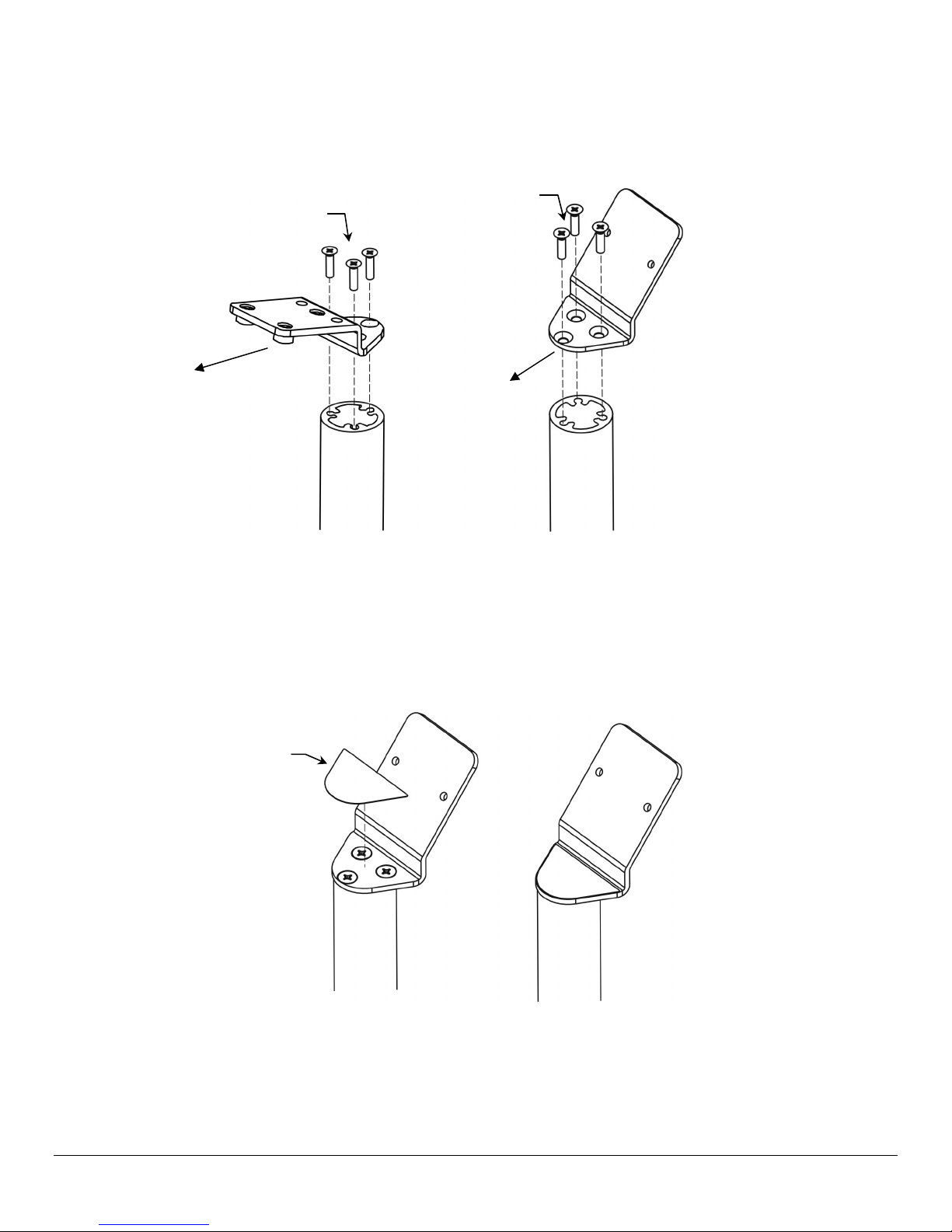
1. Align three (3) mounting holes in Fixed Tilt Mount with corresponding mounting holes in top of Post and fasten Mount
to Post with three (3) #10 x 3/4'' FHMS as shown below. Installation Note: Fixed Tilt Mount must be oriented toward
the intended front of the roll stand as shown below.
MP5 Fixed Tilt Mount
#10-32 x 3/4'' FHMS (3)
#10-32 x 3/4'' FHMS (3)
MP2 Fixed Tilt Mount
Roll Stand Front
Roll Stand Front
2. Remove backing from Lexan Screw Cover and place on top of screw heads as shown below. Procedure is same for
MP2 Mount (shown) or MP5 Mount.
3. Not shown. Align Basket and Handle with the Fixed Tilt Mount orientation and tighten mounting screws as required to
secure Basket and Handle on the Post.
Screw Cove
DU-PH-0062-60 Rev A 7/16/07 GCX Corp Page 4 of 7
Page 5
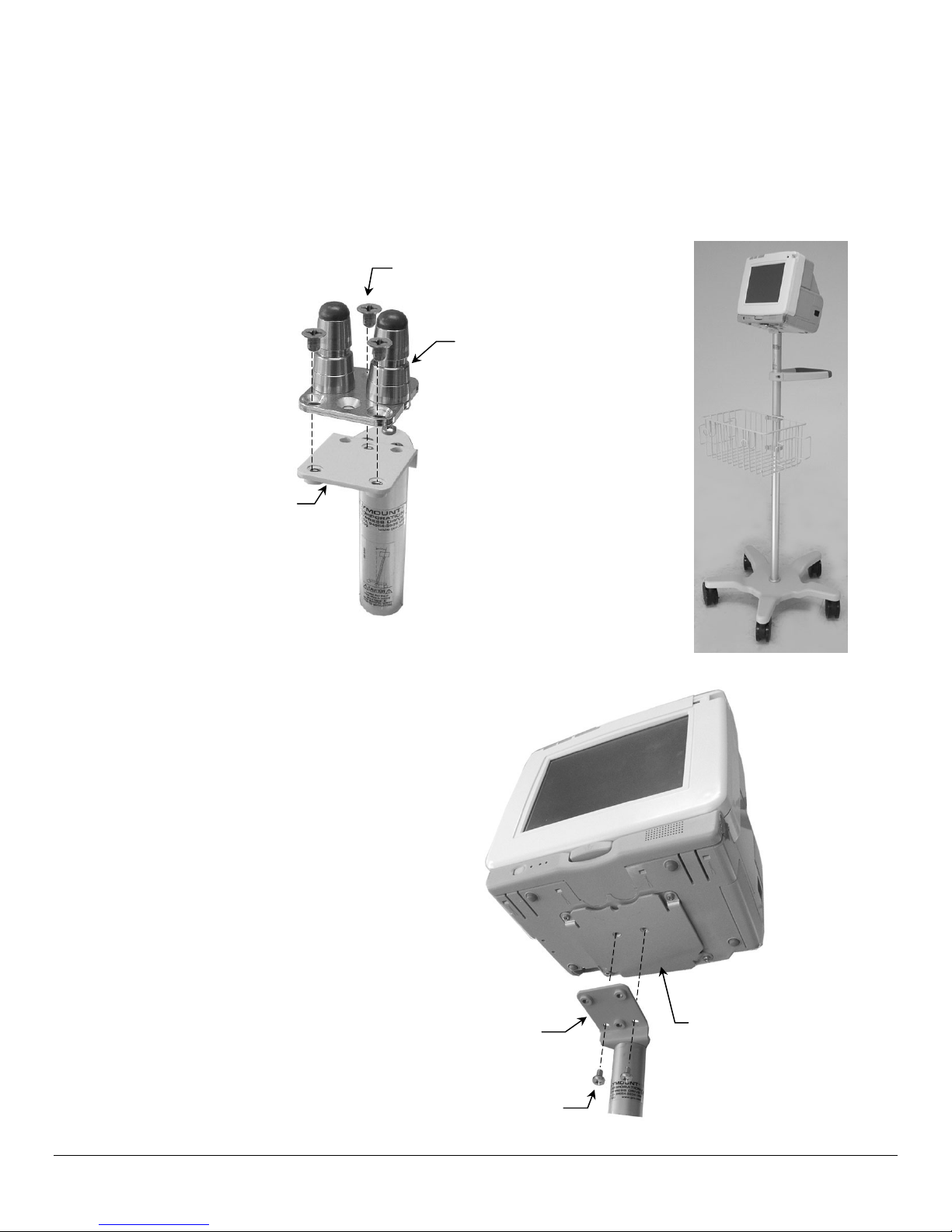
Mounting MP5 on the Roll Stand
p
The MP5 monitor will be equipped with one of two different mounting interfaces on the bottom of the monitor. The type of
interface determines which mounting procedure to follow on this page.
Mounting MP5 on Philips Table Top Mount (Requires Philips-supplied Table Top Mount)
1. Fasten the Philips-supplied table top mount to the Mounting Adapter with three (3) M6 x 10mm FHMS as shown below
left. Mount the monitor in accordance with Philips mounting instructions.
M6 x 10mm FHMS (3)
Philips-Supplied
Table To
Mount
Fixed Tilt Mount
Mounting MP5 with Non-Table Top Mounting Adapter
1. Using a Phillips screwdriver, fasten monitor to Fixed
Tilt Mount with two (2) M6 x 8 mm PHMS as shown.
Fixed Tilt Mount
M6 x 8mm PHMS (2)
DU-PH-0062-60 Rev A 7/16/07 GCX Corp Page 5 of 7
Mounting Adapter
Page 6
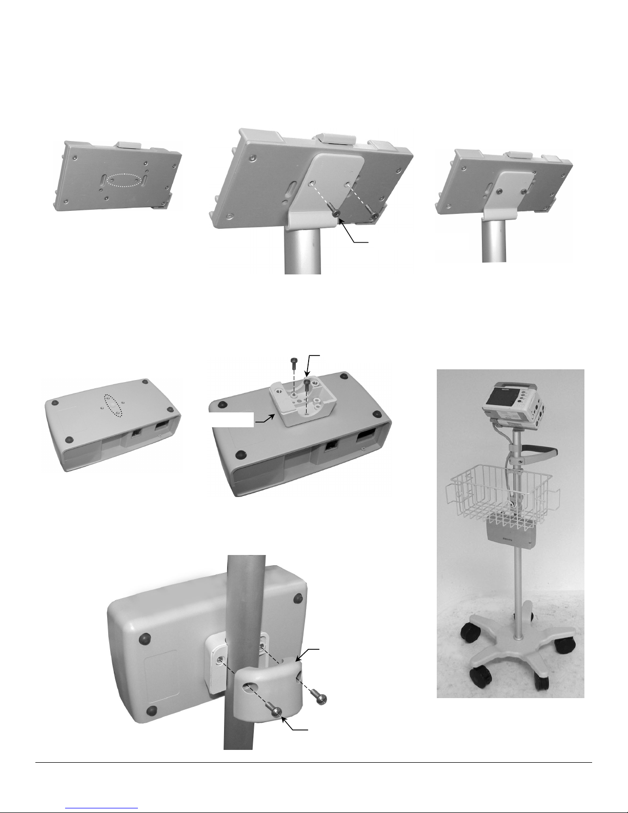
Mounting MP2
Attaching Docking Station to Fixed Tilt Mount
1. Fasten docking station to MP2 Fixed Tilt Mount with two (2) M4 x 14 mm PHMS as shown below. Mount monitor on
docking station according to manufacturer's instructions.
M4 x 14 mm PHMS (2)
Mounting the Power Supply
1. Fasten Clamping Block to power supply with two (2) M4 x 12 mm PHMS as shown below.
M4 x 12 mm PHMS (2)
Clamping Block
2. Fasten power supply to Post with rear Clamping Block and two (2)
#10-32 x 9/16'' PHMS as shown below.
Clamping Block
#10-32 x 9/16'' PHMS (2)
DU-PH-0062-60 Rev A 7/16/07 GCX Corp Page 6 of 7
Page 7
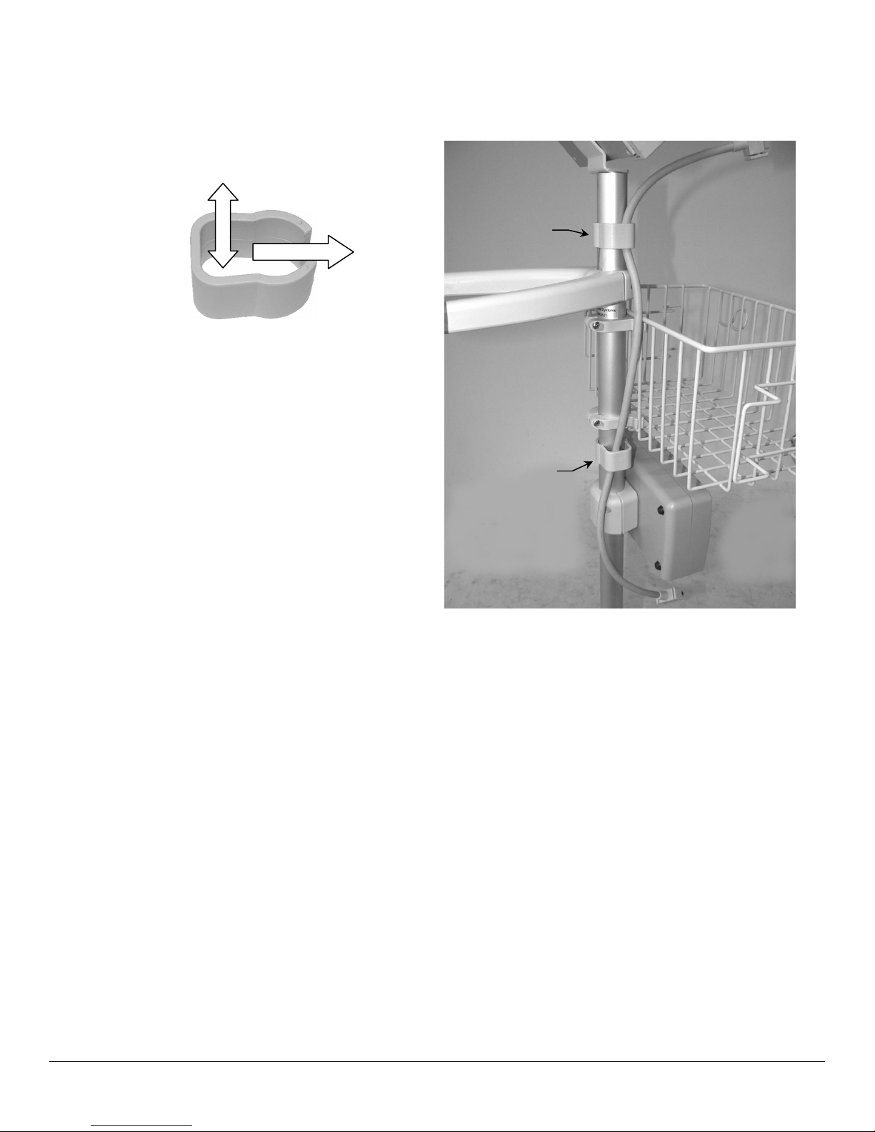
Cable Management (MP2 Only)
Two (2) Cable Clips are provided for managing cables along Roll Stand Post. Place loose cables inside Clip and slide Clip
onto Post as shown.
Routine Maintenance
Cable Clips (2)
Cables
Slide onto Post
Cable Clip
Cable Clip
Periodically check all mounting hardware. Tighten as necessary for optimal operation and safety.
Cleaning the Mounting Assembly
CAUTION: GCX makes no claims regarding the efficacy of the listed chemicals or processes as a means for controlling
infection. Consult your hospital’s infection control officer or epidemiologist. To clean or sterilize mounted instruments or
accessory equipment, refer to the specific instructions delivered with those products.
1. The mounting assembly may be cleaned with most mild, non-abrasive solutions commonly used in the hospital
environment (e.g. diluted bleach, ammonia, or alcohol solutions).
2. The surface finish will be permanently damaged by strong chemicals and solvents such as acetone and
trichloroethylene.
3. Do not use steel wool or other abrasive material to clean the mounting assembly.
4. Damage caused by the use of unapproved substances or processes will not be covered by warranty. We
recommended that you test any cleaning solution on a small area of the mounting assembly that is not visible to verify
compatibility.
5. Never submerge or allow liquids to enter the mounting assembly. Wipe any cleaning agents off the mounting assembly
immediately, using a water-dampened cloth. Dry all mounting assemblies thoroughly after cleaning.
DU-PH-0062-60 Rev A 7/16/07 GCX Corp Page 7 of 7
 Loading...