

Page 1
查询225220521101供应商
DATA SH EET
BCcomponents
Mono-axial
TM
series
Leaded ceramic multilayer
capacitors
Product specification
Supersedes data of 24th October 2001
File under BCcomponents, BC06
2002 Sep 10
Page 2
BCcomponents Product specification
Leaded ceramic multilayer
capacitors
FEATURES
• High capacitance per unit volume
• Low cost.
APPLICATIONS
These conformally coated axial leaded
capacitors are designed for
commercial and industrial
applications in four dielectrics,
NP0 (ultra-stable), X7R (stable) and
Z5U, Y5V (general purpose).
Applications include timing,
coupling/decoupling, signal
comparison and biasing.
Mono-axial™ capacitors are suitable
for automatic insertion equipment.
QUICK REFERENCE DATA
DESCRIPTION
Capacitance range 10 to 5 600 pF 100 pF to 0.22
Rated DC voltage 50 V 100 V 50 V 100 V 50V 100 V 25 V 50V
Tol erance on capacitanc e
Tem perat ure coef fici ent NP0 X7R Z5U Y5V
2252
205 .....
DESCRIPTION
The basic capacitor construction
consists of ceramic dielectric materials
processed into a tape
with a typical thickness range
from 0.025 to 0.076 mm. Metal
electrode patterns are applied using a
thick film screening process. Mult iple
layers are stacked and laminated in
such a manner that electrodes are
alternately exposed when the pattern is
cut into individual chip capacitors.
The capacitors are fired through a high
temperature profile to mature the
ceramic and metal into a
homogeneous unit.
2252
206 .....
±5% ±10% ±20% +80%/−20%
2252
225 .....
2252
226 .....
Mono-axial
Metal end terminations are applied
and fired to provide electrical
connection between the individual
layers. Tinned leads are attached using
a solder. Encapsulation consists of a
moisture resistant gold colour
conformal epoxy coating that meets
the flame requirements of “UL94V-0”.
VALUE
2252
245 .....
µF1000pFto1.0µF 0.01to1.0µF
2252
246 .....
TM
series
2252
262 .....
2252
265 .....
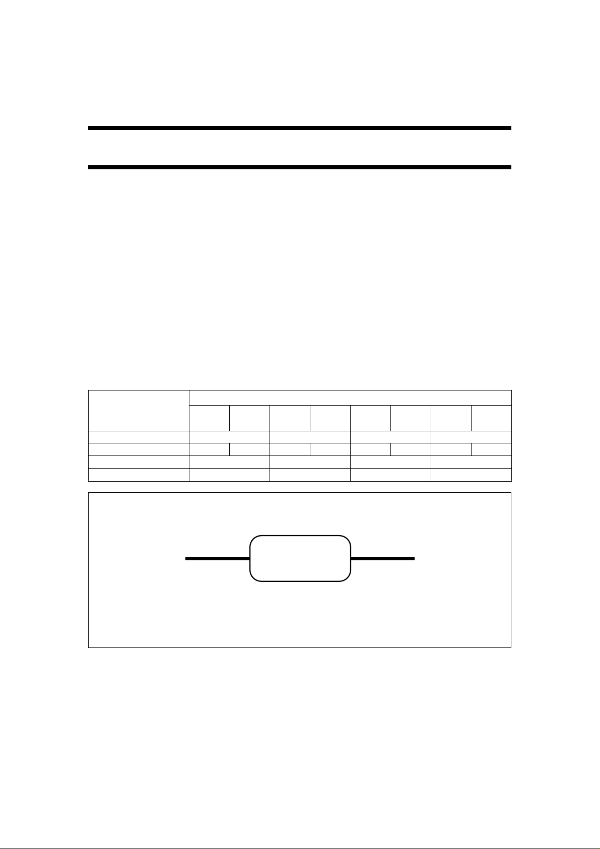
MGA331
Fig.1 Simplified outline.
2002 Sep 10 2
Page 3
BCcomponents Product specification
Leaded ceramic multilayer
capacitors
MECHANICAL DATA
Dimensions in mm.
Marking (see Fig.3)
Date code (DDD):
Three-digit code; first digit denotes
year, last two denote week of
manufacture.
941 = 1999, wk 41
Capacitance value (CCC):
10 pF to 99 pF; actual value in pF
(2 digits only)
100 pF and above; coded
capacitance value
(same as used in P/N).
Capacitance tolerance (T):
Standard EIA tolerance
(same as used in P/N).
Material code (M):
A=C0G
C=X7R
E=Z5U
Y=Y5V.
Voltage code (V):
1 = 100 V
3=25V
5=50V.
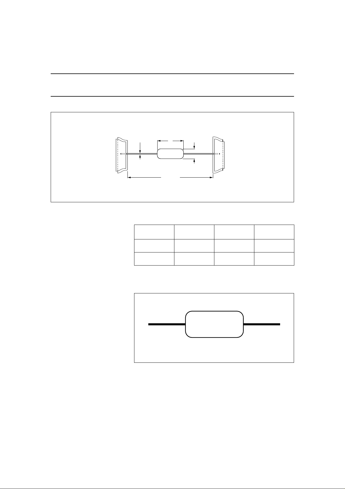
Physical dimensions
Ta ble 1 Capacitor dimensions and mass
Note
1. Dimensions between parentheses are in inches.
L
52.4 ±1.5
Fig.2 Tape carrier.
SIZE
15
20
Mono-axial
5 mm or
6.35 mm wide
carrier tape
∅D∅0.5
CCA974
(1)
L
max
(mm)
3.8
(0.150)
5.0
(0.200)
CCCT
Fig.3 Markings on the body.
BC
M V
DDD
∅D
max
(mm)
2.5
(0.100)
3.0
(0.120)
TM
series
(1)
MASS
(g)
≈0.14
≈0.14
JW62
2002 Sep 10 3
Page 4
BCcomponents Product specification
Leaded ceramic multilayer
capacitors
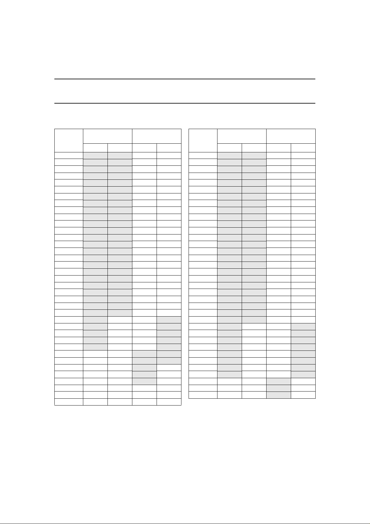
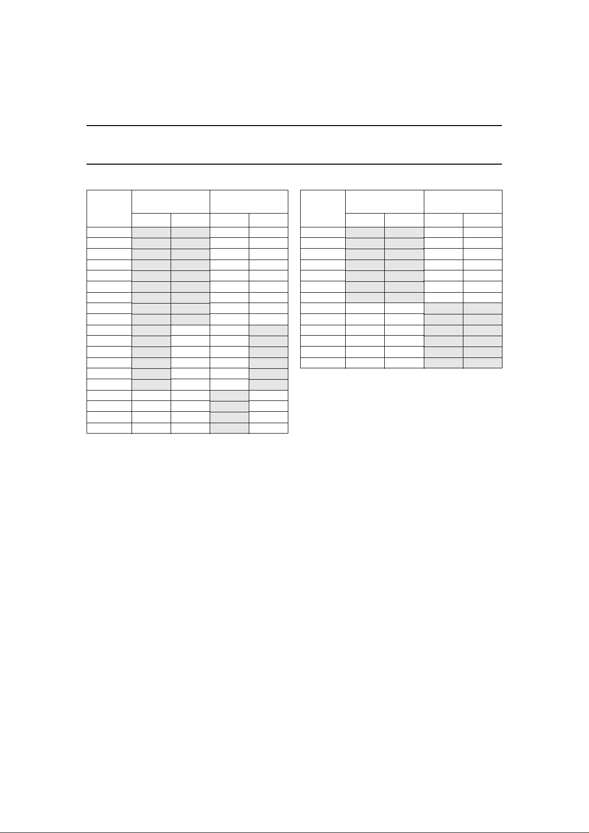
CAPACITANCE RANGE CHARTS
NP0 Dielectric
10 pF
12
15
18
22
27
33
39
47
56
68
82
100
120
150
180
220
270
330
390
470
560
680
820
1000
1200
1500
1800
2200
2700
3300
3900
4700
5600
6800
8200
0.01
CAP .
µF
SIZE CODE
15
50 V 100 V 50 V 100 V
SIZE CODE
20
X7R Dielectric
CAP .
100-220 pF
270
330
390
470
560
680
820
1000
1200
1500
1800
2200
2700
3300
3900
4700
5600
6800
8200
0.01 µF
0.012
0.015
0.018
0.022
0.027
0.033
0.039
0.047
0.056
0.068
0.082
0.10
0.12
0.15
0.22
TM
Mono-axial
SIZE CODE
15
50 V 100 V 50 V 100 V
series
SIZE CODE
20
2002 Sep 10 4
Page 5
BCcomponents Product specification
Leaded ceramic multilayer
capacitors
Z5U Dielectr ic
CAP .
1000 pF
1500
2200
3300
4700
6800
0.01 µF
0.015
0.022
0.033
0.047
0.068
0.10
0.15
0.22
0.33
0.47
0.68
1.0
SIZE CODE
15
50 V 100 V 50 V 100 V
SIZE CODE
20
Y5V Dielectric
CAP .
µF
0.01
0.015
0.022
0.033
0.047
0.068
0.10
0.15
0.22
0.33
0.47
0.68
1.0
TM
Mono-axial
SIZE CODE
15
25 V 50 V 25 V 50 V
series
SIZE CODE
20
2002 Sep 10 5
Page 6

BCcomponents Product specification
Leaded ceramic multilayer
capacitors
ORDERING INFORMATION
Components may be ordered by using either a simple 15-digit clear text code, or BCcomponents 12NC.
Clear text code
XAMPLE: A103K15X7RF5TAA
E
PRODUCT
TYPE
A =mono-axial two significant digits
Ordering code 12NC
CAPACITANCE
(pF)
followed by the number
of zeros:
101 =100
103 =10000
Dielectric and
tolerance
NP0 ±5%
20
NP0 ±10%
21
X7R ±10%
22
X7R ±20%
23
Z5U ±20%
24
Z5U −20/+80%
25
Y5V −20/+80%
26
Rated voltage (DC)
2
25 V
5
50 V
6
100 V
TOLERANCE
J=±5%
K=±10%
M=±20%
Z =+80%/−20%
SIZE CODE
(mm)
15 =
3.8 (.150") max.
20 =
5.0 (.200") max.
DIELECTRIC
COG (NP0)
X7R
Z5U
Y5V
2 2 5 2 X X X X X X X X
JWB217
Mono-axial
RATED
VOLTAGE
E=25V
F = 50 V
H = 100 V
Multiplier
8
9
1
2
3
4
5
Capacitance (pF)
two significant digits
of capacitance value
Size and packaging
20
21
40
41
5=
0.5 (0.020") max.
0.1
1
10
100
1 000
10 000
100 000
size 15/tape and reel
size 15/ammo
size 20/tape and reel
size 20/ammo
LEAD DIA.
(mm)
TM
series
PACKAGING
TAA= tape & reel
UAA =ammopack
2002 Sep 10 6
Page 7

BCcomponents Product specification
Leaded ceramic multilayer
capacitors
Table 2 Capacitance, rated voltage, mechanical dimensions and ordering information
U
C
NP0 (C0G)
±5% tolerance
10 pF
12 pF 50 15 A120J15C0GF5UAA 2252 205 21129
15 pF 50 15 A150J15C0GF5UAA 2252 205 21159
18 pF 50 15 A180J15C0GF5UAA 2252 205 21189
22 pF
27 pF 50 15 A270J15C0GF5UAA 2252 205 21279
33 pF 50 15 A330J15C0GF5UAA 2252 205 21339
39 pF 50 15 A390J15C0GF5UAA 2252 205 21399
47 pF
56 pF 50 15 A560J15C0GF5UAA 2252 205 21569
68 pF 50 15 A680J15C0GF5UAA 2252 205 21689
82 pF 50 15 A820J15C0GF5UAA 2252 205 21829
100 pF
150 pF 50 15 A151J15C0GF5UAA 2252 205 21151
220 pF
330 pF 50 15 A331J15C0GF5UAA 2252 205 21331
470 pF
680 pF 50 15 A681J15C0GF5UAA 2252 205 21681
1000 pF
1500 pF 50 15 A152J15C0GF5UAA 2252 205 21152
2200 pF 50 15 A222J15C0GF5UAA 2252 205 21222
3300 pF 50 20 A332J20C0GF5UAA 2252 205 41332
4700 pF 50 20 A472J20C0GF5UAA 2252 205 41472
5600 pF 50 20 A562J20C0GF5UAA 2252 205 41562
R(DC)
(V)
50 15 A100J15C0GF5UAA 2252 205 21109
100 15 A100J15C0GH5UAA 2252 206 21109
50 15 A220J15C0GF5UAA 2252 205 21229
100 15 A220J15C0GH5UAA 2252 206 21229
50 15 A470J15C0GF5UAA 2252 205 21479
100 15 A470J15C0GH5UAA 2252 206 21479
50 15 A101J15C0GF5UAA 2252 205 21101
100 15 A101J15C0GH5UAA 2252 206 21101
50 15 A221J15C0GF5UAA 2252 205 21221
100 15 A221J15C0GH5UAA 2252 206 21221
50 15 A471J15C0GF5UAA 2252 205 21471
100 15 A471J15C0GH5UAA 2252 206 21471
50 15 A102J15C0GF5UAA 2252 205 21102
100 20 A102J20C0GH5UAA 2252 206 41102
SIZE
CODE
CLEAR TEXT CODE CATALOGUE NUMBER
Mono-axial
TM
series
2002 Sep 10 7
Page 8

BCcomponents Product specification
Leaded ceramic multilayer
capacitors
U
C
X7R ±10% tolerance
100 pF
150 pF
220 pF
330 pF 50 15 A331K15X7RF5UAA 2252 225 21331
470 pF
680 pF 50 15 A681K15X7RF5UAA 2252 225 21681
1000 pF
1500 pF 50 15 A 152K15X7RF 5UAA 2252 225 21152
2200 pF
3300 pF 50 15 A 332K15X7RF 5UAA 2252 225 21332
4700 pF
6800 pF 50 15 A 682K15X7RF 5UAA 2252 225 21682
µF
0.01
µF 50 15 A153K15X7RF5UAA 2252 225 21153
0.015
0.022
µF
µF 50 15 A333K15X7RF5UAA 2252 225 21333
0.033
µF
0.047
µF 50 15 A683K15X7RF5UAA 2252 225 21683
0.068
0.1
µF
R(DC)
(V)
50 15 A101K15X7RF5UAA 2252 225 21101
100 15 A101K15X7RH5UAA 2252 226 21101
50 15 A151K15X7RF5UAA 2252 225 21151
100 15 A151K15X7RH5UAA 2252 226 21151
50 15 A221K15X7RF5UAA 2252 225 21221
100 15 A221K15X7RH5UAA 2252 226 21221
50 15 A471K15X7RF5UAA 2252 225 21471
100 15 A471K15X7RH5UAA 2252 226 21471
50 15 A102K15X7RF5UAA 2252 225 21102
100 15 A102K15X7RH5UAA 2252 226 21102
50 15 A222K15X7RF5UAA 2252 225 21222
100 15 A222K15X7RH5UAA 2252 226 21222
50 15 A472K15X7RF5UAA 2252 225 21472
100 15 A472K15X7RH5UAA 2252 226 21472
50 15 A103K15X7RF5UAA 2252 225 21103
100 15 A103K15X7RH5UAA 2252 226 21103
50 15 A223K15X7RF5UAA 2252 225 21223
100 15 A223K15X7RH5UAA 2252 226 21223
50 15 A473K15X7RF5UAA 2252 225 21473
100 20 A473K20X7RH5UAA 2252 226 41473
50 15 A104K15X7RF5UAA 2252 225 21104
100 20 A104K20X7RH5UAA 2252 226 41104
SIZE
CODE
CLEAR TEXT CODE CATALOGUE NUMBER
Mono-axial
TM
series
2002 Sep 10 8
Page 9

BCcomponents Product specification
Leaded ceramic multilayer
capacitors
U
C
Z5U ±20% tolerance
1000 pF
2200 pF 50 15 A222M15Z5UF5UAA 2252 245 21222
4700 pF 50 15 A472M15Z5UF5UAA 2252 245 21472
µF
0.01
0.022
µF 50 15 A223M15Z5UF5UAA 2252 245 21223
µF 50 15 A473M15Z5UF5UAA 2252 245 21473
0.047
µF
0.1
µF 50 15 A224M15Z5UF5UAA 2252 245 21224
0.22
0.47
µF 50 20 A474M20Z5UF5UAA 2252 245 41474
µF 50 20 A684M20Z5UF5UAA 2252 245 41684
0.68
1.00
µF 50 20 A105M20Z5UF5UAA 2252 245 41105
Y5V +80/
−20% tolerance
µF 50 15 A103Z15Y 5VF5UA A 2252 265 21103
0.01
µF 50 15 A223Z15Y 5VF5UA A 2252 265 21223
0.022
µF 50 15 A473Z15Y 5VF5UA A 2252 265 21473
0.047
µF
0.1
0.22
µF
µF
0.47
µF 25 20 A105Z20Y 5VE5UA A 2252 262 41105
1.0
R(DC)
(V)
50 15 A102M15Z5UF5UAA 2252 245 21102
100 15 A102M15Z5UH5UAA 2252 246 21102
50 15 A103M15Z5UF5UAA 2252 245 21103
100 15 A103M15Z5UH5UAA 2252 246 21103
50 15 A104M15Z5UF5UAA 2252 245 21104
100 20 A104M20Z5UH5UAA 2252 246 41104
25 15 A104Z15Y5VE5U A A 2252 262 21104
50 15 A104Z15Y5VF5U A A 2252 265 21104
25 20 A224Z20Y5VE5U A A 2252 262 41224
50 20 A224Z20Y5VF5U A A 2252 265 41224
25 20 A474Z20Y5VE5U A A 2252 262 41474
50 20 A474Z20Y5VF5U A A 2252 265 41474
SIZE
CODE
CLEAR TEXT CODE CATALOGUE NUMBER
Mono-axial
TM
series
2002 Sep 10 9
Page 10

BCcomponents Product specification
Leaded ceramic multilayer
capacitors
ELECTRICAL CHARACTERISTICS
Table 3 Electrical data for NP0, X7R, Z5U and Y5V
The capacitors meet the essential requirements of “EIA 198”.
Unless stated otherwise all electrical values apply at an ambient temperature of 25
650 to 800 mm of mercury, and relative humidity not to exceed 75%.
DESCRIPTION VALUE
Capacitors with temperature coefficient NP0
Capacitance range:
at 1MHz, 1V; where C
at 1 kHz, 1 V; where C
Tol erance on the capaci ta nce
Rated DC voltage 50 and 100 V
Dielectric strength 250% of rated voltage
Insulation resistance at rated voltage 100 000 M
Temperature coefficient of the capacitance 0
Tol erance on the tempe rature coeffic ient
Dissipation factor:
at 1MHz, 1V; where C
at 1 kHz, 1 V; where C > 30 pF <15 × 10
Operating temperature range −55 to +125 °C
Storage temperature range 25
Capacitors with temperature coefficient X7R
Capacitance range at 1 kHz, 1 V 100 pF to 0.22
Tol erance on the capaci ta nce
Maximum capacitance change
with respect to capacitan ce value at 25
Rated DC voltage 50 V and 100 V
Dielectric strength 250% of rated voltage
Insulation resistance at rated voltage 100 000 M
Dissipation factor at 1 kHz, 1 V
Operating temperature range
Storage temperature range 25
Ageing typical 1% per time decade
≤ 1000 pF 10 to 1000 pF
> 1000 pF 1200 to 5600 pF
Ω or 1000 MΩ×µF, whichever is less at rated
voltage within 2 minutes of charging
≤ 30 pF
°C
Ω or 1000 MΩ×µF, whichever is less at rated
voltage within 2 minutes of charging
Mono-axial
±3 °C, at barometric pressures of
±5%; ±10%
−6
× 10
/K
±30 × 10
--------------------------------------
<
±10%; ±20%
−55 to +125 °C
−6
/K
1
400 20 C
×+()
−4
±15 °C
±15%
≤2.5%
±15 °C
µF
TM
series
2002 Sep 10 10
Page 11

BCcomponents Product specification
Leaded ceramic multilayer
capacitors
DESCRIPTION VALUE
Capacitors with temperature coefficient Z5U
Capacitance range at 1 kHz, 0.5 V 1 000 pFto 1.00
Tol erance on the capaci ta nce
Maximum capacitance change
with respect to capacitan ce value at 25
Rated DC voltage 50 and 100 V
Dielectric strength 250% of rated voltage
Insulation resistance at rated voltage 10 000 M
Dissipation factor at 1 kHz, 0.5 V ≤4%
Operating temperature range 10 to 85
Storage temperature range 25
Ageing typical 6% per time decade
Capacitors with temperature coefficient Y5V
Capacitance range at 1 kHz, 1 V 0.01 to 1.0
Tol erance on the capaci tance +80%/
Maximum capacitance change
with respect to capacitan ce value at 25
Rated DC voltage 25 V and 50 V
Dielectric strength 250% of rated voltage
Insulation resistance at rated voltage 10 000 M
Dissipation factor at 1 kHz, 1 V
Operating temperature range
Storage temperature range 25
Ageing typical 6% per time decade
°C
Ω or 1000 MΩ×µF, whichever is less at rated
voltage within 2 minutes of charging
°C
Ω or 1000 MΩ×µF, whichever is less at rated
voltage within 2 minutes of charging
Mono-axial
µF
±20%; +80%/−20%
+22%/
−56%
°C
±15 °C
µF
−20%
+22%/
−82%
≤5%
−30 to +85 °C
±15 °C
TM
series
2002 Sep 10 11
Page 12

BCcomponents Product specification
7
Leaded ceramic multilayer
capacitors
PACKAGING
Table 4 Packaging quantities and box dimensions; see Fig.6
PACKAGING SIZE CODE
Tap e on reel 15; 20 700 0 370
Ammopack 15; 20 4 00 0 265
Capacitors on bandolier
P
SMALLEST PACKAGING
QUANTITY (SPQ)
C
Mono-axial
BOX DIMENSIONS
A
TM
L
× W × H
(mm)
× 370 × 90
× 85 × 95
series
H
S
M
MGA34
B
Maximum 0.1% of the total number of capacitors per reel may be missing.
A maximum of 1 consecutive vacant position is followed by 6 consecutive components.
Tape begins and ends with minimum of 60 empty positions (300 mm tape).
Maximum of 5 splices per reel.
For dimensions see Table 5.
T
Fig.4 Capacitors on bandolier.
2002 Sep 10 12
Page 13

BCcomponents Product specification
Leaded ceramic multilayer
capacitors
Mono-axial
TM
series
Table 5 Dimensions of bandolier; seeFig.4
SYMBOL PARAMETER
(1)
B
inside tape spacing 52.4 ±1.5 2.062 ±0.059
C centre-to-tape-spacing
P cumulative pitch, 6 consecutive components
A components pitch 5
DIMENSIONS
mm inch
±0.8 ±0.031
±1.5 ±0.059
±0.5 0.197 ±0.015
M lead bend <1.2 <0.047
S exposed adhesive <0.51 <0.020
T tape width 6.35 0.250
H lead sandwich >3.96 >0.156
Note
1. Inside tape spacing 26.0 +1.51/
EEL DATA
R
−0.0 is available on request.
69.85
+
1.5
–
355.6
max
direction
of
unreeling
MGA351 - 1
Dimensions in mm.
Maximum 0.1% of the total number of capacitors per reel may be missing.
A maximum of 1 consecutive vacant position is followed by 6 consecutive components.
Tape begins and ends with minimum of 60 empty positions (300 mm tape).
Maximum of 5 splices per reel.
For capacitor length (L) and diameter (∅D), see Table 1.
arbor hole
+
Ø 28
–
1.5
Fig.5 Reel with capacitors on tape.
2002 Sep 10 13
Page 14

BCcomponents Product specification
2
Leaded ceramic multilayer
capacitors
AMMOPACK DATA
T
L
Dimensions in mm.
Maximum 0.5% of the total number of capacitors per box may be missing.
A maximum of 2 consecutive vacant positions is followed by 6consecutive components.
Tape begins and ends with minimum of 24 empty positions (300 mm tape).
Maximum of 5 splices per box.
Cumulative pitch tolerance over 20 consecutive units not to exceed ±1.0 mm.
Lead space (F) shall be measured at 3.6±0.5 mm from the capacitor seating plane.
For dimensions see Table 4.
Mono-axial
JWB24
W
TM
series
Fig.6 Ammopack with capacitors on tape.
2002 Sep 10 14
 Loading...