

Philips MDV434/55, MDV434K/55, SDV434/19, MDV43477 Service Manual
. Technical Specifications…………………………………….………1-2
. Safety Instructions, Warnings, Notes...……………………...…….1-3
. Mechanical and Dismantling Instructions…………………....……2-1
. Region Code, Software Version& Upgrades………………...…....3-1
. Trouble Shooting Chart…………………………………..…….……4-1
. Block and Wiring Diagram…………………………………….…….5-1
. Electrical Diagrams and Print-layouts
Front Board……………………………...…………………………..6-1
Power Board………………………………………………………...7-1
Main Board………………..………………………….…….….…….8-1
. Set Mechanical Exploded view& Parts List………………………..9-1
. Revision List………………………………………………..……......10-1
DVD Player MDV434 (K)/XX
Service
TABLE OF CONTENTS
Page
3139 785 31220
Version 1.0
Service Manual
PHILIPS
GB
Copyright 2005Philips Consumer Electronics B.V. Eindhoven, The Netherlands
A
ll rights reserved. No part of this publication may be reproduced, stored in aretrieval system or
transmitted, in any form or by any means, electronic, mechanical, photocopying, or otherwise
without the prior permission of Philips.
CLASS 1
LASER PRODUCT
Published by TCL-KC 0511 Service Audio Printed in The Netherlands Subject to modification
C
MDV434K/55
MDV434/55/77
SDV434/19

Technical Specifications
TV standard (PAL/50Hz) (NTSC/60Hz)
Number of lines 625 525
Playback Multi standard (PAL/NTSC)
Video performance
Video DAC 12 bit, 108mH
PbPr: 0.7Vpp ---- 75ohm
Video output 1Vpp ----- 75ohm
Video format
Digital Compression MPEG 2 for DVD,SVD
MPEG 1 for VCD
DVD 50Hz 60Hz
Horiz. resolution 720 pixels 720 pixels
Vertical resolution 576lines 480 lines
VCD 50Hz 60Hz
Horiz. resolution 352 pixels 352 pixels
Vertical resolution 288lines 240 lines
Audio format
Digital MPEG/AC-3/ Compressed Digital
PCM 16, 20, 24bits
fs, 44.1, 48, 96kHz
MP3(ISO 9660) 96,112,128,256kbps
& variable bit rate fs,32,
44.1,48 kHz
Analogue Sound Stereo
Dolby surround-compatible downmix from Dolby Digital multi-channel
sound
Audio performance
DA converter 24bits, 192KHz
DVD fs 96kHz 4Hz----44kHz
fs 48kHz 4Hz----22kHz
SVCD fs 48kHz 4Hz----22kHz
fs 44.1kHz 4Hz----20kHz
CD/VCD fs 44.1kHz 4Hz----20kHz
Signal-Noise (1kHz) >95dB
Dynamic Range (1kHz) >85dB
Cross talk (1kHz) >90dB
Distortion/Noise (1kHz) >80dB
MPEG MP3 MPEG Audio L3
Audio L+R output: 1.0~2.0 Vpp into 10K ohm
Connections
YpbPr Cinch 3x
Video output Cinch( yellow)
Audio L+R output Cinch (white/red)
Digital output 1 coaxial
IEC60958 for CDDA/LPCM
IEC61937 for MPEG1/2,
Dolby Digital
Cabinet
Dimensions (w X h X d) 360 X 37 X 265mm
Weight Approximately 2.0 kg
Power consumption
Power supply 110-240V Rating
Power consumption in standby mode < 0.8W
Power consumption <10W
Specifications subjects to change without prior notice.
1-2

Safety instructions
1. General safety
Safety regulations require that during a repair:
. Connect the unit to the mains via an isolation transformer.
. Replace safety components indicated by the symbol
,
only by components identical to the original ones. Any other
component substitution (other than original type) may
increase risk of fire or electrical shock hazard.
Safety regulations require that after a repair, you must return
the unit in its original condition. Pay, in p articular, attention to
the following points:
. Route the wires/cables correctly, and fix them with the
mounted cable clamps.
. Check the insulation of the mains lead for external
damage.
. Check the electrical DC resistance between the mains plug
and the secondary side:
1) Unplug the mains cord, and connect a wire between
the two pins of the mains plug.
2) Set the mains switch the “on” position (keep the
mains cord unplug).
3) Measure the resistance value between the mains
plug and the front panel, controls, and chassis
bottom.
4) Repair or correct unit when the resistance
measurement is less than 1M
Ω
.
5) Verify this, before you return the unit to the
customer/user (ref. UL-standard no. 1492).
6) Switch the unit “off”, and remove the wire between
the two pins of the mains plug.
2.Laser safety
This unit employs a laser. Only qualified service personnel
may remove the cover, or attempt to service this device (due
to possible eye injury).
Laser device unit
Type : Semiconductor laser GaAlAs
Wavelength : 650nm (DVD)
: 780nm (VCD/CD)
Output power : 7mW (DVD)
: 10mW (DVD /CD)
Beam divergence: 60 degree
Note: Use of controls or adjustments or performance of
procedure other than those specified herein, may result in
hazardous radiation exposure. Avoid direct exposure to
beam.
Safety instructions, Warnings, Notes
1-3
Warnings
1.General
. All ICs and many other semiconductors are susceptible to
electrostatic discharges (ESD). Careless handing during
repair can reduce life drastically. Make sure that, during
repair, you are at the same potential as the mass of the set
by a wristband with resistance. Keep components and tools
at this same potential. Available ESD protection equipment:
1) Complete kit ESD3 (small tablemat, wristband,
connection box, extension cable and earth cable) 4822
310 10671.
2) Wristband tester 4822 344 13999.
. Be careful during measurements in the live voltage section.
The primary side of the power supply , including the heat
sink, carries live mains voltage when you connect the player
to the mains (even when the player is “off”!). It is possible to
touch copper tracks and/or components in this unshielded
primary area, when you service the player. Service
personnel must take precautions to prevent touching this
area or components in this area. A “lighting stroke” and a
stripe-marked printing on the printed wiring board, indicate
the primary side of the power supply.
. Never replace modules, or components, while the unit is
“on”.
2. Laser
. The use of optical instruments with this product, will
increase eye hazard.
. Only qualified service personnel may remove the cover or
attempt to service this device, due to possible eye injury.
. Repair handing should take place as much as possible with
a disc loaded inside the player.
. Text below is placed inside the unit, on the laser cover
shield:
Notes: Manufactured under licence from Dolby Laboratories.
The double-D symbol is trademarks of Dolby Laboratories,
Inc. All rights reserved.
CAUTION: VISIBLE AND INVISIBLE LASER RADIATION
WHEN OPEN, AVOID EXPOSURE TO BEAM.
1-4

Lead-Free requirement for service
INDENTIFICATION:
Regardless of special logo (not always indicated)
One must treat all sets from 1.1.2005 onwards, according next
rules.
Important note: In fact also products a little older can
also be treated in this way as long as you avoid mixing
solder-alloys (leaded/ lead-free). So best to always
use SAC305 and the higher temperatures belong to
this.
Due to lead-free technology some rules have to be respected by the
workshop during a repair:
• Use only lead-free solder alloy Philips SAC305 with
order code 0622 149 00106. If lead-free
solder-paste is required, please contact the
manufacturer of your solder-equipment. In general
use of solder-paste within workshops should be
avoided because paste is not easy to store and to
handle.
• Use only adequate solder tools applicable for
lead-free solder alloy. The solder tool must be able
o To reach at least a solder-temperature of
400°C,
o To stabilize the adjusted temperature at the
solder-tip
o To exchange solder-tips for different
applications.
• Adjust your solder tool so that a temperature a round
360°C
– 380°C is reached and stabilized at the
solder joint. Heating-time of the solder-joint should
not exceed ~ 4 sec. Avoid temperatures above
400°C otherwise wear-out of tips will rise drastically
and flux-fluid will be destroyed. To avoid wear-out of
tips switch off un-used equipment, or reduce heat.
• Mix of lead-free solder alloy / parts with leaded
solder alloy / parts is possible but PHILIPS
recommends strongly to avoid mixed
solder alloy types (leaded and lead-free). If one
cannot avoid, clean carefully the
solder-joint from old solder alloy and re-solder with
new solder alloy (SAC305).
• Use only original spare-parts listed in the
Service-Manuals. Not listed standard-material
(commodities) has to be purchased at
external companies.
• Special information for BGA-ICs:
- always use the 12nc-recognizable soldering
temperature profile of the specific BGA (for
de-soldering always use highest lead-free
temperature profile, in case of doubt)
- lead free BGA-ICs will be delivered in
so-called ‘dry-packaging’ (sealed pack
including a silica gel pack) to protect the IC
against moisture. After opening, dependent of
MSL-level seen on indicator-label in the bag,
the BGA-IC possibly still has to be baked dry.
This will be communicated via AYS-website.
Do not re-use BGAs at all.
• For sets produced before 1.1.2005, containing
leaded soldering-tin and components, all
needed spare-parts will be available till the
end of the service-period. For repair of such
sets nothing changes.
• On our website:
www.atyourservice.ce.Philips.com
You find more information to:
BGA-de-/soldering (+ baking instructions)
Heating-profiles of BGAs and other ICs used
in Philips-sets
You will find this and more technical
information within the “magazine”, chapter
“workshop news”.
For additional questions please contact your local
repair-helpdesk.
Warnings, Notes
1-5
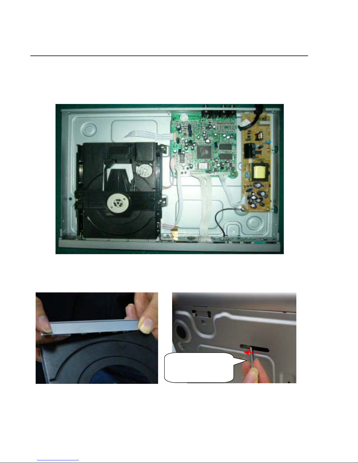
Mechanical and Dismantling Instructions
Dismantling Instruction
The following guidelines show how to dismantle the player.
Step1: Remove 5 screws around the Top Cover. And remove
it (Figure 1)
Step2: If it is necessary to dismantle Loader or Front Panel,
It should be remove the front door assembly first. (Figure 2)
If the trace can’t open in normal way, you can make it by
pushing the guider manually using the slot below the bottom
chassis with a tool. (Figure 3)
Note: Make sure to operate gently otherwise the guider would
be damaged.
2-1
Figure 2
Figure 1
Figure 3
Push the guider until the
trace out. Make sure to
operate gently to avoid
dama
g
ehappening.
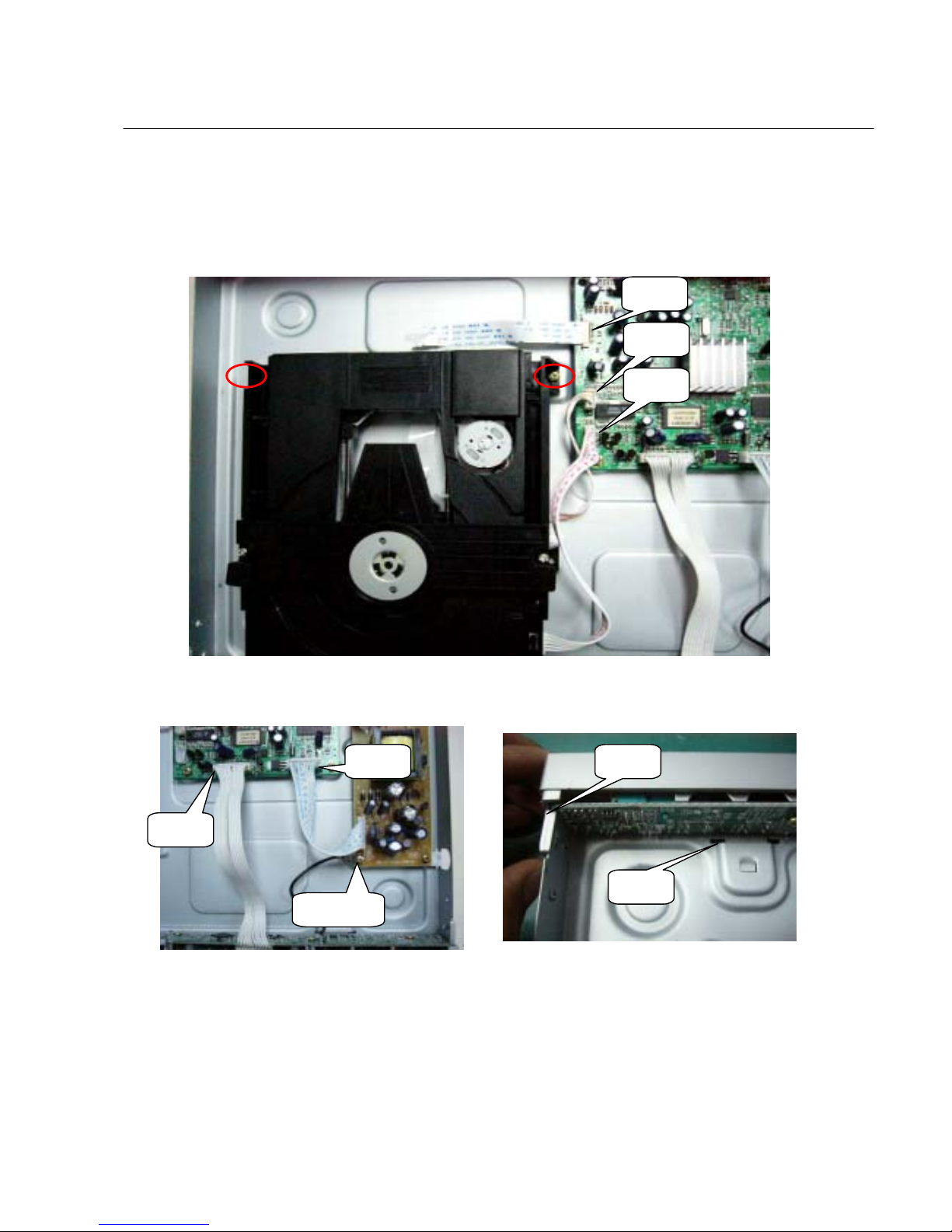
Mechanical and Dismantling Instructions
Step3: Dismantling Loader, First, disconnect the 3 connectors
aiming in the figure, and then remove the 2 screws at both
sides of the loader, (Figure 4)
Step4: Dismantling Front Panel: disconnect the 2 connectors
aiming in the figure then Release the snaps on the both sides
of Front Panel and gently pull the Panel out from the set.
Figure4
Figure 5 Figure 6
Snap1
Snap2
CON 1
CON 2
CON 3
CON 4
CON 5
2-2
(Figure5& 6)
GND cable
Mechanical and Dismantling Instructions
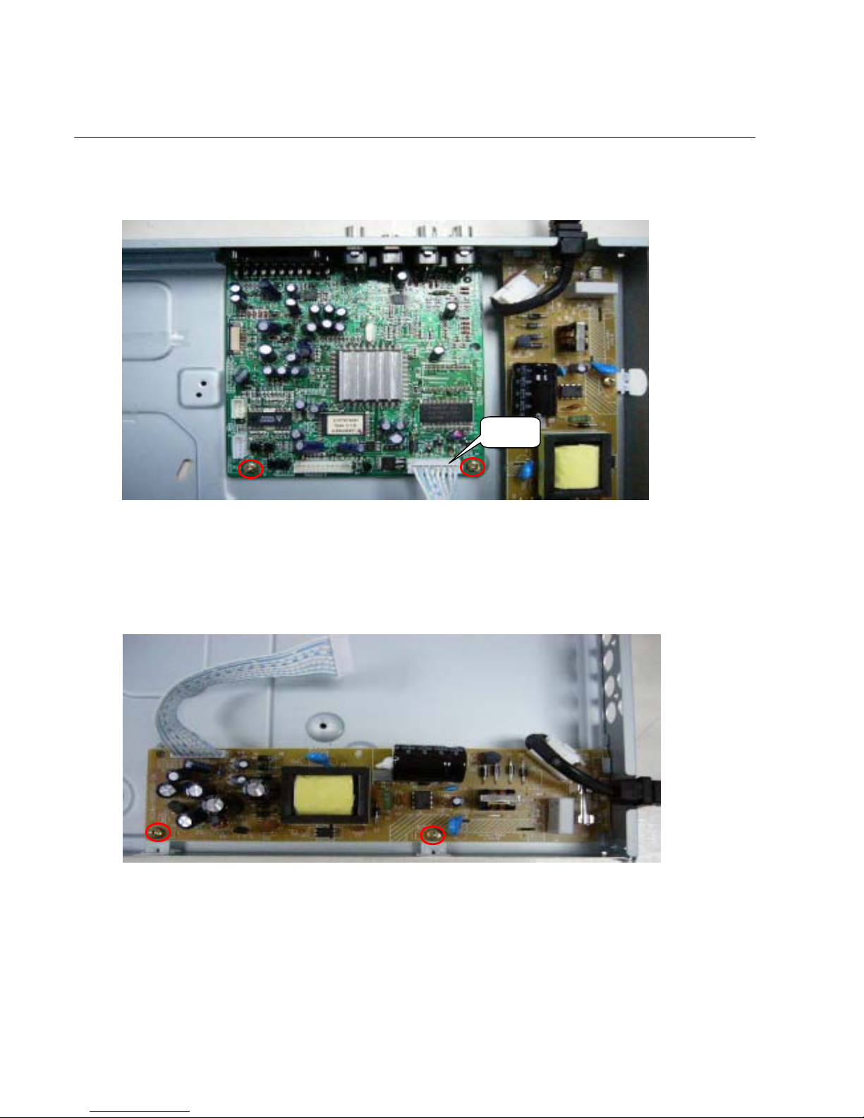
Step6: Dismantling Main Board, first disconnect the
connector, and then remove the relative screws, (Figure 7)
Step7: Remov e the 3 screws on power board to dismantle
the power board. (Figure8)
Figure 8
CON 6
2-3
Figure 7
Mechanical and Dismantling Instructions
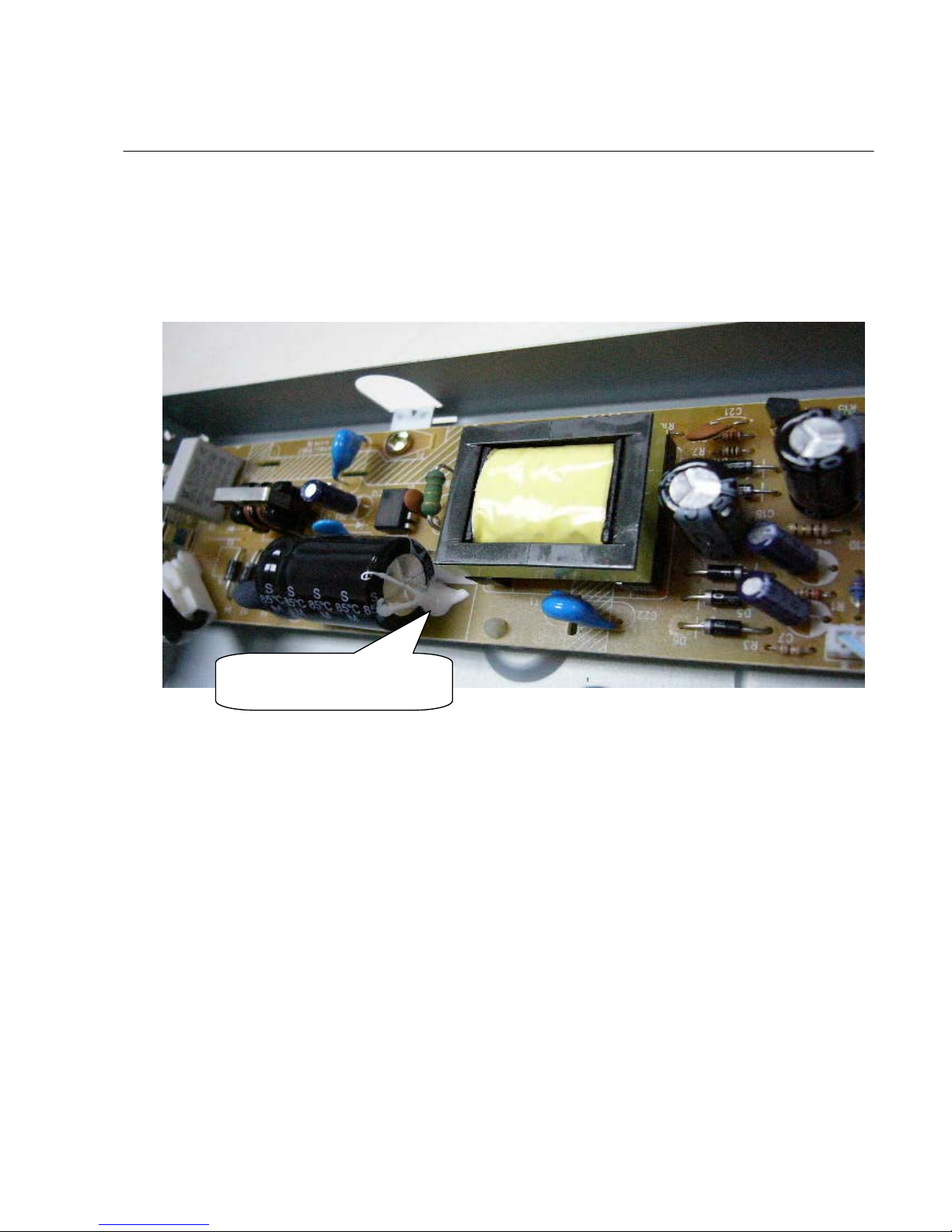
ATTENTION OF REPAIRING
Make sure adding silicon glue to fix the capacitor C4 after repairing, ( Avoid the hazard of C4 touching the Top
Cover.)
Figure 9
A
dd Silicon glue or Heat glue to fi
x
C4 to keep this status
2-4

Software upgrade
A. Preparation to upgrade software
1) Start the CD Burning software and create a new CD
project (Data Disc) with the following setting:
Label: ______
(No need the Label name)
File System: MDV434K_55.BIN (for MDV434K/55)
MDV434_55.BIN (for MDV434/55)
MDV434_77.BIN (for MDV434/77)
MDV434_19.BIN (for SDV434/19)
Note: It is required capital letter for the Label name &
the File System name.
2) Burn the data onto a blank CDR
B. Procedure for software upgrade:
1) Power up the set and insert the prepared Upgrade
CDR.
2) The set will starts reading disc & response with the
following display TV screen:
Upgrade File DETECTED
Upgrade?
Press Play TO START
3) Press <OK> button to confirm, then screen will display :
Files coping…
UPGRADING…
3) The upgraded disc will automatically out when files
coping complete, then take out the disc.
4) About 1 minute later, the trace will automatically close
when upgrading complete.
C. Read out the software versions to confirm upgrading
1) Power up the set and press <system menu> button on
the remote control.
2) Press <1><3><7><9> button.
The software version and other information are display
on the TV screen as follows:
Version XX.XX.XX.XX (Main version)
SUB-VER XX.XX.XX.XX ( software version of
application software)
8032 XX.XX.XX.XX
Servo XX.XX.XX.XX (software version of Servo)
RISC XX.XX.XX.XX
DSP XX.XX.XX.XX
Region Code X
3-1
Caution: The set must not be power off during
upgrading, in that case the decoder board will
be damaged entirely.
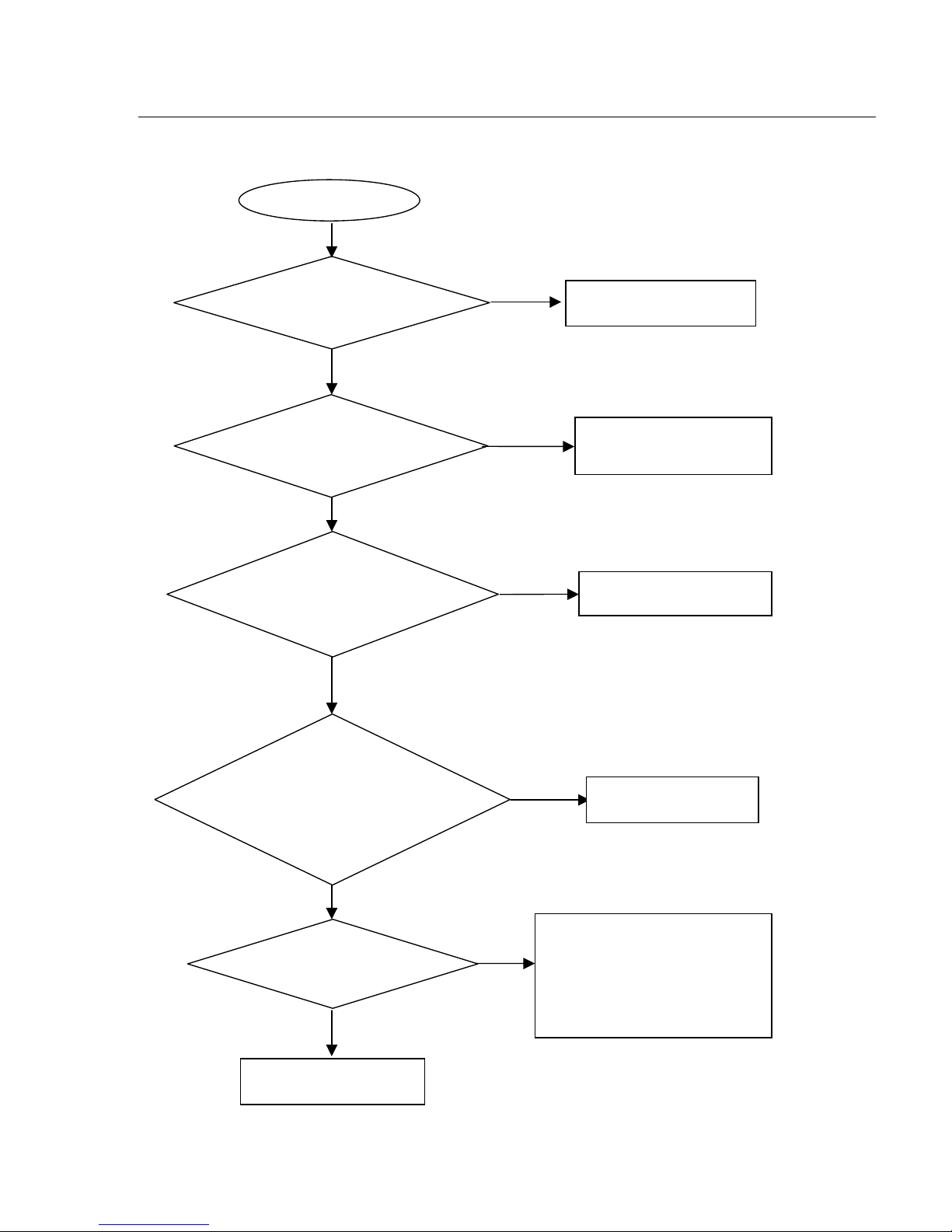
4-1
Spindle motor does not move
Yes
Yes
No
No
No
No
Yes
Check whether “AVCC”
(+5V) voltage is normal.
Correct connection
Check the AVCC power
supply
Check/Replace Q8、Q9.
Check/ Replace U3.
Have no to focus
1. Check U3 42pin FOO signals
2.If there are F+, F-, T+ and Tsignals output from U2.
Check/Replace the loader
Yes
Yes
No
Go
Check whether laser voltage
(2V for VCD & 2.2V for DVD)
on Collector of Q8 and Q9
Check the FFC connection
between 24P and the loader.
1.Whether voltage on pin 44 of U3
varies between 0 and 3.3V (3.3V fo
r
VCD and 0V for DVD),
2.Whether peripheral components
are eroded or badly soldered.
Trouble shooting chart
Motor no move
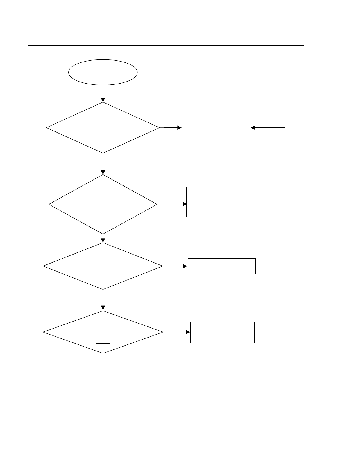
4-2
The power can not be on or off
Go
Yes
Yes
No
No
The power can’t be
on or off
Yes
Repair the power board
Check the power suppl
y
on the power board is
normal.
Check/Correct
connection
Whether the connection
to K301 is broken.
Correct the connection
Replace U3.
No
No
Yes
Yes
Check if the CON2 on the
front board to CN6 on the
decoder board is in good
contact.
Whether there is 0V and
3.3V voltage difference on
Pin 100 PCON
of U3.
Trouble shooting chart
4-3
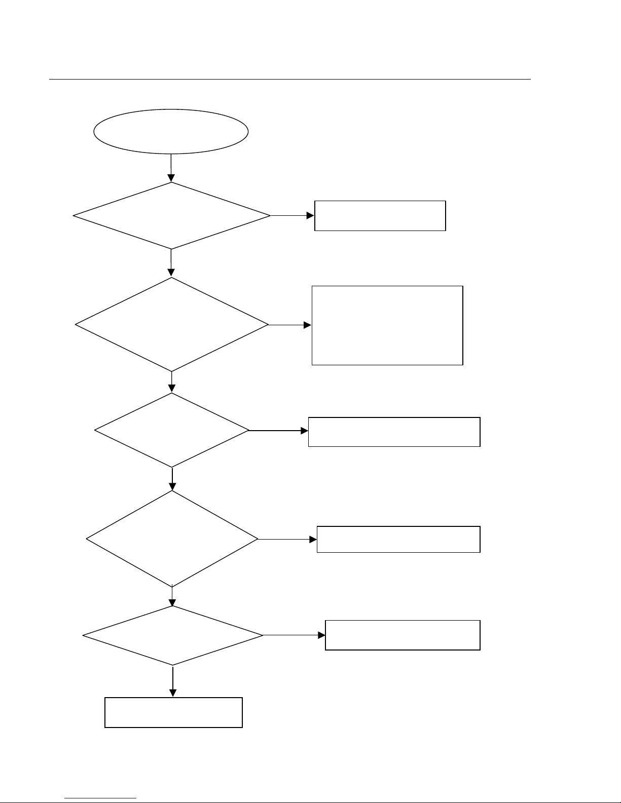
All output voltages on the power board is 0V or deviated.
No
No
No
Yes
No
U1(PIN 8 - Drain waveform)
Replace F1
Replace C4 if D1, D2, D3, D4 are
normal.
Check/ replace U1.
Check whether U1 are eroded.
A
ll output voltages on
the power board is 0V o
r
deviated
Check whether there is
300V on C4.
Check whether 100KHz
oscillating signal on
Pin6 of U1
Check if +5V, +3.3v, +12V,
-12V and -24V are short.
Check whether the components in the
short-circuit voltage are defected or eroded.
Yes
Yes
Yes
Yes
U1(PIN 3 - RC waveform)
Trouble shooting chart
Check whether
F1 is blown
4-4
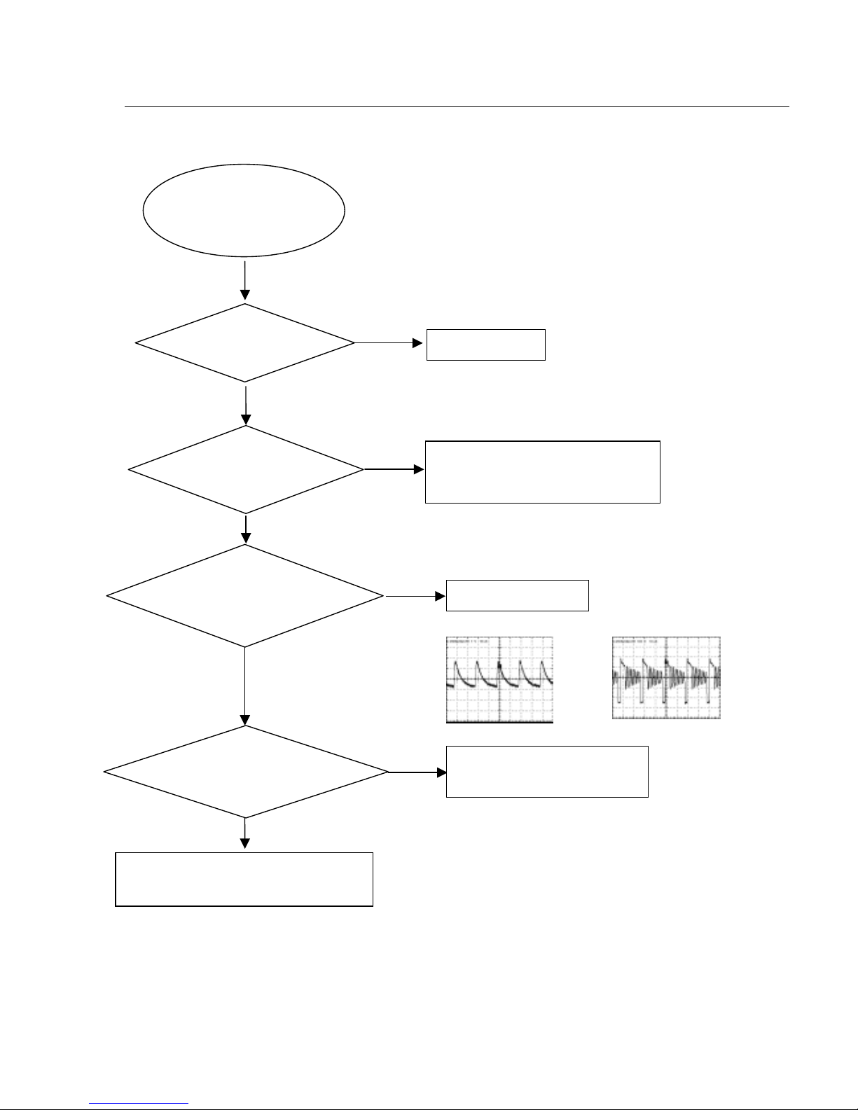
Disc cannot be read.
No
Yes
No
Yes
No
Yes
Yes
No
No
Yes
Disc cannot be read.
Check the loaded circuit
1.Check voltage on pin 44 of U3 varies
between 0 and 3.3V:
Æ3.3V for VCD
Æ0V for DVD
2.Check whether peripheral components
are eroded or defect
Check the FFC connection
between 24P and the loader.
Check U3 and peripheral components
Re-solder or replace the defective parts
Check the connection
between U3
Correct connection
Replace U3 or loader.
Yes
Check whether there is lase
r
voltage (2V for VCD and 2.2V fo
r
DVD) on Collector of Q8 &Q9
Check if there is RFO signal on
pin8 of CN2. (The normal RFO
signal is a clear reticulated wave)
Trouble shooting chart
Check U3, U6, and
peripheral components are
eroded or badly soldered.
 Loading...