

Philips MCD-702, MCD-700, MCL-707 Service Manual
DVD Micro System
MCD700, MCD702
MCL707
all versions
TABLE OF CONTENTS
Handling chip components ........................................................... 1-1
Service tools ................................................................................. 1-1
Leadfree and safety information ................................................... 1-2
Technical specification .................................................................. 2-1
Service measurement setup ......................................................... 2-2
Connections and controls ..................................................... 3-1...3-3
Disassembly diagram ........................................................... 4-1...4-2
Software version and upgrading ................................................... 5-1
Block diagram ............................................................................... 6-1
Wiring diagram ............................................................................. 6-2
VFD / Key Board Assembly
circuit diagram .......................................................................... 7-1
layout diagram .......................................................................... 7-2
DVD Block
circuit diagram .......................................................................... 8-1
layout diagram .......................................................................... 8-2
©
Copyright 2005 Philips Consumer Electronics B.V. Eindhoven, The Netherlands
All rights reserved. No part of this publication may be reproduced, stored in a retrieval
system or transmitted, in any form or by any means, electronic, mechanical, photocopying,
or otherwise without the prior permission of Philips.
Tuner board
circuit diagram. ......................................................................... 9-1
layout diagram .......................................................................... 9-2
DVD / MPEG board
circuit diagram .............................................................. 10-1...10-3
layout diagram ....................................................................... 10-4
AMP Block
circuit diagram. ........................................................................11-1
layout diagram .........................................................................11-2
Exploded view diagram ............................................................... 12-1
Mechanical partslist ........................................................... 12-2...12-3
Electrical partslist ..............................................................13-1...13-2
MCL707/61 partslist ..........................................................14-1...14-2
Revision list ................................................................................. 15-1
Published by YT 0531 Service Audio Subject to modification
Version 1.2
© 3141 785 30432

HANDLING CHIP COMPONENTS
1 - 1

1 - 2

SPECIFICATION
2 - 1
GENERAL
Mains voltage -/55/96/98 : 120 / 230 V
/93 : 220V
/79 : 240V
/37 : 120V
Mains frequency -/55/96/98 : 50 / 60 Hz
/79/93 : 50 Hz
/37 : 60 Hz
Battery for remote : 3V (R03, AAA x 2)
Power consumption Max. : < 32 W (max.)
Standby : < 5 W
Dimension (W x H x D)
DVD Part : 208 x 62 x 244 mm
AMP Part : 208 x 57 x 244 mm
Weight DVD Part : 1.4 Kg
AMP Part : 2.4 Kg
AMPLIFIER
Output power : 2 x 25 W RMS
: 1000 W PMPO
Speaker impedance : 2 x 8 ohm
Frequency response : 100 Hz - 20 kHz (±3dB)
Aux input sensitivity : 350 mV (600 ohm)
DVD / MP3 / CD
Laser Type : Semiconductor
Disc Diameter : 12cm / 8cm
Video Decoding : MPEG-2 / MPEG-1
Signal System : PAL / NTSC
Video S/N : 53 dB (min.)
Composite Video Output : 1.0 Vp-p, 75
S-Video Output : Y - 1.0 Vp-p, 75
C - 0.286 Vp-p, 75
Audio DAC : 24 Bits / 96 kHz
Frequency Response : 4 Hz - 20 kHz (44.1kHz)
4 Hz - 22 kHz (48kHz)
4 Hz - 44 kHz (96kHz)
Digital Output : SPDIF (Sony Philips
digital interface) Coaxial
No. of programmable tracks : 20
Signal-to-noise ratio : 50 dBA
Channel separation : 40 dB (1 kHz)
Total harmonic distortion : < 0.02% (1 kHz)
TFT LCD PANEL
Number of pixels(HXV) : 280x220
Brightness dark room : >150cd/m2
Contrast dark room : 150 :1
TUNER - FM SECTION
Tuning range : 87.5 – 108 MHz
IF frequency : 10.7 MHz ± 0.2 MHz
Sensitivity : 26 dBf at 46dB S/N
Selectivity : 20 dB at 300kHz
IF rejection : 50 dB
Image rejection : 20 dB
TUNER - AM SECTION
Tuning range MW(9 kHz) : 531 - 1602 kHz
AM (10 kHz) : 530 – 1700 kHz
IF frequency : 450 kHz ± 3 kHz
Sensitivity MW : 4000 µV/m at 26dB S/N
Selectivity MW : 16 dB
IF rejection MW : 24 dB
Image rejection MW : 20 dB
LOUDSPEAKERS
2-way bass reflex system
Dimension (W x H x D) : 145 x 230 x 210 mm
Weight : 2.4 Kg each
SERVICE MEASUREMENT
2 - 2
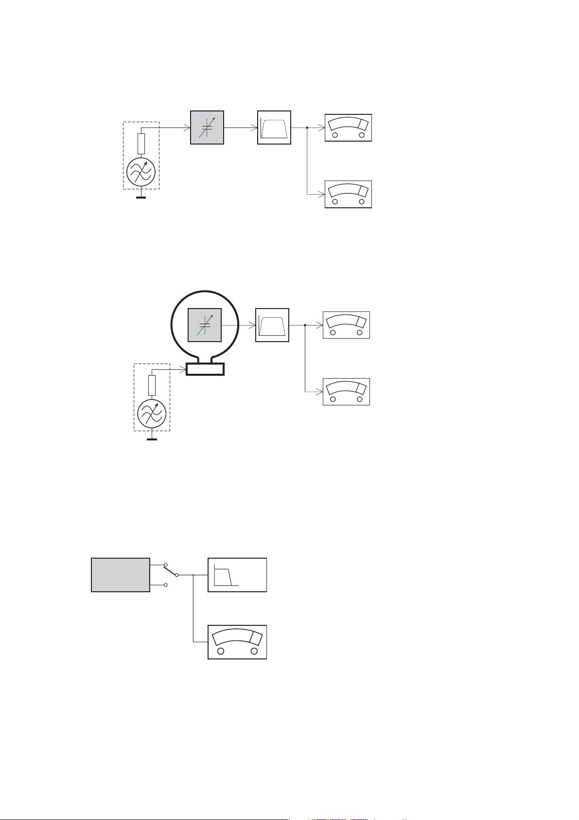
Tuner FW
RF Generator
e.g. PM5326
DUT
Bandpass
250Hz-15kHz
e.g. 7122 707 48001
LF Voltmeter
e.g. PM2534
½
Ri=50
S/N and distortion meter
e.g. Sound Technology ST1700B
Use a bandpass filter to eliminate hum (50Hz, 100Hz) and disturbance from the pilottone (19kHz, 38kHz).
Tuner AM (MW,LW)
RF Generator
e.g. PM5326
½
Ri=50
DUT
Frame aerial
e.g. 7122 707 89001
Bandpass
250Hz-15kHz
e.g. 7122 707 48001
LF Voltmeter
e.g. PM2534
S/N and distortion meter
e.g. Sound Technology ST1700B
To avoid atmospheric interference all AM-measurements have to be carried out in a Faraday«s cage.
Use a bandpass filter (or at least a high pass filter with 250kHz) to eliminate hum (50Hz, 100Hz).
CD RECORDER
Use Audio Signal Disc SBC429 4822 397 30184
(replaces test disc 3)
DUT
L
R
S/N and distortion meter
e.g. Sound Technology ST1700B
LEVEL METER
e.g. Sennheiser UPM550
with FF-filter
Use Universal Test Cassette Fe SBC420 4822 397 30071
LF Generator
e.g. PM5110
DUT
½
Ri=50
L
R
S/N and distortion meter
e.g. Sound Technology ST1700B
LEVEL METER
e.g. Sennheiser UPM550
with FF-filter
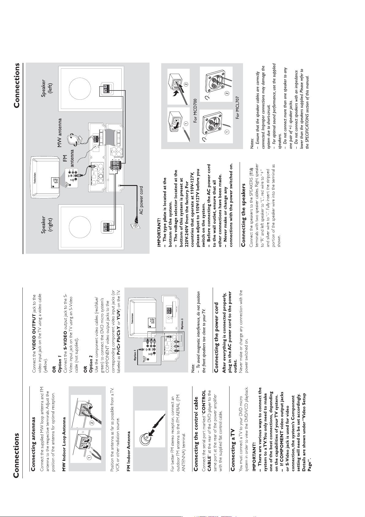
CONNECTION AND CONTROLS
3 - 1

CONNECTION AND CONTROLS
3 - 2
For more information onoperation instruction please visit Philips Audio
internet site :
http://www.audio.philips.com

CONNECTION AND CONTROLS
3 - 3
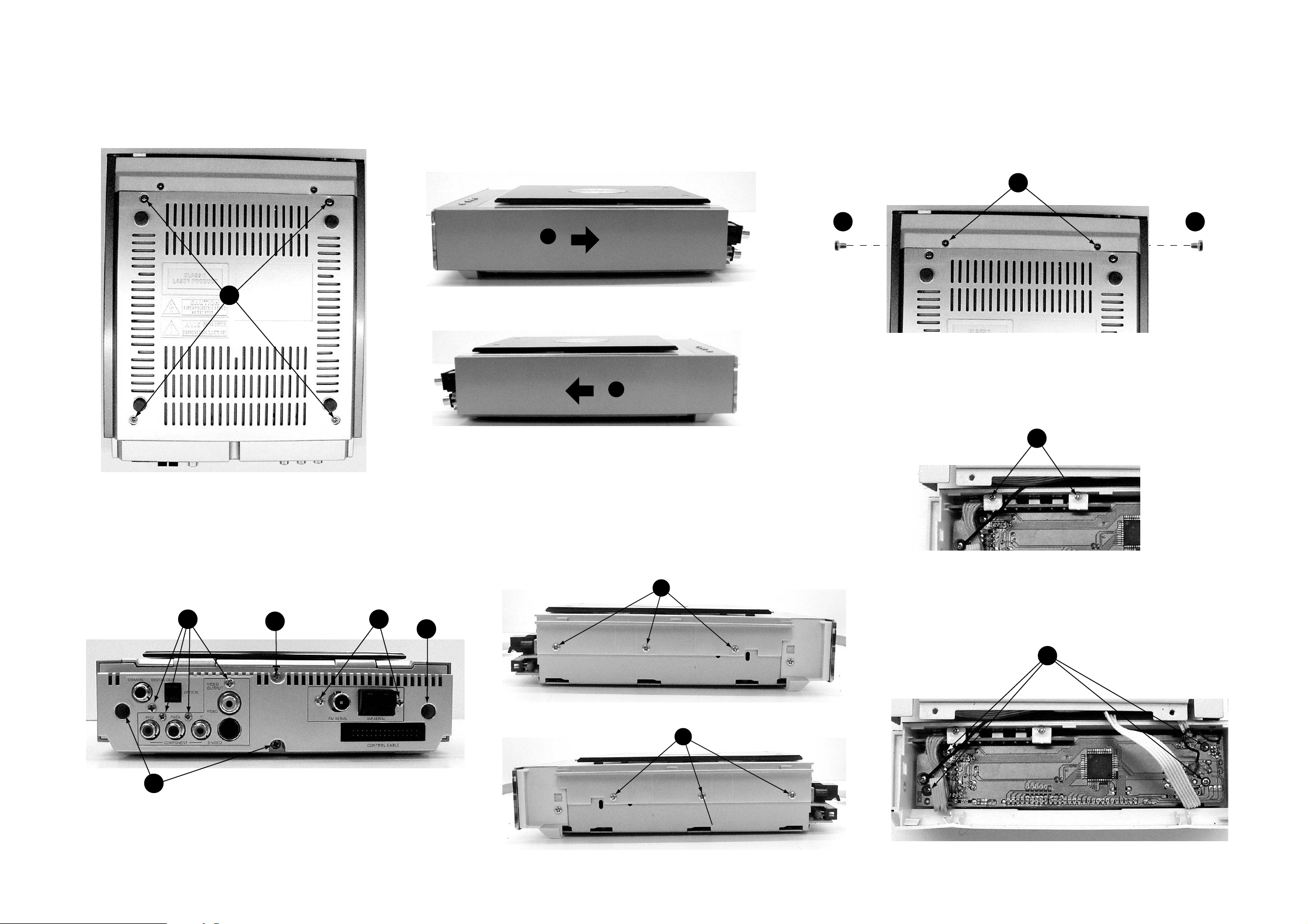
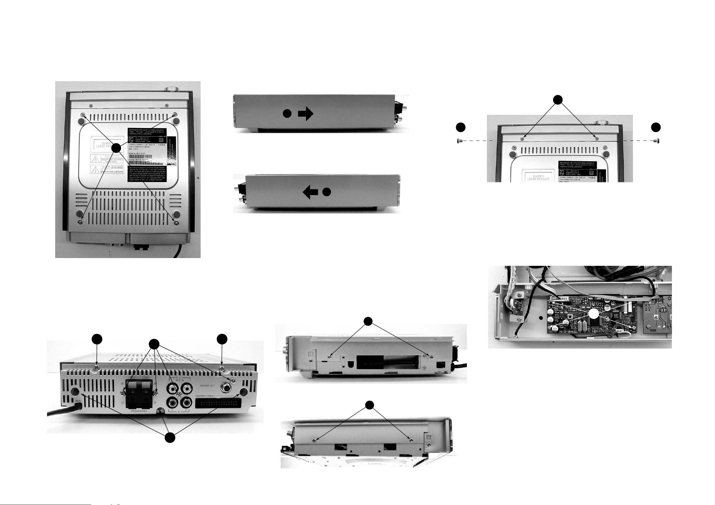
DISASSEMBLY INSTRUCTION - DVD PART
4 - 1 4 - 1
A. Remove Bottom Cover
A1 remove screws M2.5x4 (washer head) - 4 pcs.
A1
C. Remove Side Panel (L & R)
C1 Slide out the Side Panels.
C1
C1
E. Remove Front Cabinet
E1 remove screws MK3x10 - 2 pcs.
E2 remove screws M3x4 - 2 pcs.
E1
E2E2
F. Remove Display Board Assembly
F1 remove screws ST 2.5x8 - 2 pcs.
(take out Push Key PCB Assy)
B. Remove Back Panel
B1 remove screws M3x6 - 3 pcs.
B2 remove screw ST 3x10 - 1 pc.
B3 remove screws ST 3x10 - 6 pcs. (for jacks)
B2
F1
D. Remove Top Cabinet
D1 remove screws M3x6 - 3 pcs.
D2 remove screws M3x6 - 3 pcs.
D1
F. Remove Display Board Assembly
F2 remove screws ST 2.5x8 - 4 pcs.
B3B3
B1
F2
D2
B1
DISASSEMBLY INSTRUCTION - AMP PART
4 - 2 4 - 2
A. Remove Bottom Cover
A1 remove screws M2.5x4 (washer head) - 4 pcs.
A1
C. Remove Side Panel (L & R)
C1 Slide out the Side Panels.
C1
E. Remove Front Cabinet
E1 remove screws MK3x10 - 2 pcs.
E2 remove screws M3x4 - 2 pcs.
E1
E2E2
C1
F. Remove TFT Module (for MCL707 only)
F1 remove screws ST 2.5x8 - 4 pcs.
B. Remove Back Panel
B1 remove screws M3x6 - 3 pcs.
B2 remove screw ST 3x10 - 2 pc.
B3 remove screws ST 3x10 - 4 pcs. (for jacks)
B3
D. Remove Top Cabinet
D1 remove screws M3x6 - 2 pcs.
D2 remove screws M3x6 - 2 pcs.
F1
D1
B2B2
D2
B1

SOFTWARE VERSION AND UPGRADING
5 - 1
5 - 1
A. MPEG SOFTWARE VERSION CHECK
1. Press SYSTEM button (on the remote control) to enter general setting page.
TV Screen shows
2. Press button (on the remote control) to select Preference Page.
TV Screen shows
3. Press “811502” button (on the remote control).
TV Screen shows
TV Setting
OSD Lang.
Screen Saver
TV set standard
Sound
Subtitle
Language chosen by disk
Ver MCD707/xx V1.1
Date mmm dd yyyy
Time hh : mm : ss
Region code 3
/xx : /versiom
C. MPEG SOFTWARE UPGRADING:
1. Download the firmware for Philips support website
http://www.philips.com/support
2. Prepare as uploading CD.
3. Load the CD in the CD Tray.
4. TV Screen shows
Upgrade file detected
Upgrade?
Press PLAY to start
Upgrading
and upgrading will run automatically
3. Press oTbutton (on the remote control) to change region.
Press OK to confirm.
B. CPU VERSION CHECK
1. Keep PLAY and STOP buttons (on the set) while plug in the power cord.
TV Screen shows
MCD700 V1.0
 Loading...